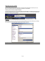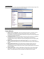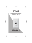
1
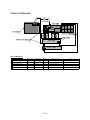
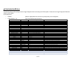
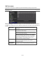
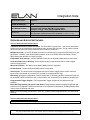
Integration Note
Manufacturer:
ELAN
Model Number(s):
S8.6
Core Module Version:
Comments:
Document Revision Date:
Core Module ver. 4.0 rel 1288 or later
Version 5.0 (g!) requires S86 FW 2.0.1.3 or newer
Version 5.1/5.2 (g! – HC’s) requires S86 FW 2.3.1.2
S8.6 Firmware compatible with 4.0: 1.0.2.1 – 1.0.4.1 & 1.2.1.1
S8.6 Firmware versions that are NOT compatible 1.1.0.3 – 1.1.2.1
1/14/2013
OVERVIEW AND SUPPORTED FEATURES
THE FOLLOWING FEATURES ARE SUPPORTED:
Traditional Whole-House Audio and Video: The ELAN S8.6 is a multi-zone – multi-source audio/video
switcher that can be controlled by the g! software using its serial (RS-232) port. The g! Viewer interface
can be used to select sources by zone, and control volume in each zone.
Multiple S8.6 units: Up to 4 ELAN S8.6 units can be controlled using a single serial (RS-232) port in the
g! software. In addition, other ELAN System products, such as the ELAN V883 Video Switch, can be
daisy chained with the S86 on a single com port.
Independent Zone Settings: Volume, Bass and Treble can be adjusted independently for each zone.
Audio and Video Source Sensing: Source signal sensing is supported and can be used to trigger
events in the g! system.
Whole House Music: The Whole House Music (WHM) feature is supported.
Do Not Disturb: The Do Not Disturb (DND) feature is supported.
Sense Inputs: The sense inputs are supported and can be used to trigger system events. Note that
inputs need to be shorted for a minimum of 5 seconds for reliable detection in g!
IR Routing: g! supports configuration of the ELAN S86 built in IR Routing abilities. Note that IR must still
be generated outside the S86 (from HC or Global Cache etc), as the S86 is not capable of generating IR.
Programmable Trigger Outputs: The Programmable Trigger Outputs can be utilized via the g!
Software.
ELAN S86 Programming (Version 5.0 and above): The g! software supports programming ELAN S86
features from Configurator, and ELAN VIA!Tools is not required for most features, including WHM modes,
volume levels, IR Routing and more.
Note: If you have already programmed in VIA!Tools, existing programming should carry over and not be
affected.
THE FOLLOWING FEATURES ARE SUPPORTED:
Any feature not specifically noted as supported should be assumed to be unsupported.
ELAN Home Systems ● 1690 Corporate Circle ● Petaluma, CA 94954 USA
tech support: 800.622.3526 • main: 760.710.0990 • sales: 877.289.3526 • email: [email protected]
©2013 ELAN Home Systems. All rights reserved. ELAN and g! are trademarks of ELAN Home Systems. All other trademarks are the property of their respective owners.
INSTALLATION OVERVIEW
1. During the rough-in phase, install speaker wire for the speakers and Cat5 cable for keypads, in each
zone.
2. Also during the rough-in phase, run a Cat5 wire from the location of the ELAN back to the Network
Assembly of the g! system for RS-232 communications. Refer to the RS-232 Connection Options
Integration Note for other options.
3. Mount the speakers and keypads in each zone, and install the ELAN and the sources.
4. Setup the ELAN to operate as desired using the VIA!Tools software. Refer to ELAN documentation
for details. (Not Required in version 5.0 and above)
5. Confirm proper audio and video switching as configured in step above.
6. Connect the g! system to the ELAN system electrically. See the wiring diagrams for more information.
7. Configure the g! system for the ELAN and confirm communication between the ELAN and the
Controller.
8. Test the system by changing sources in a zone to confirm the correct source plays and volume is
controlled. Test source control for any sources that are to be controlled from the g! interface.
2 of 8
CONNECTION DIAGRAM
BILL OF MATERIALS
#
D e v ic e
M a nuf a c t ure r
N/A
P a rt N umbe r
N/A
P ro t o c o l
A nalo g
C o nne c t o r T ype
1
RCA Cable
2
IR Flasher
Nuvo
NV-VEC
IR
M ini Jack X IR Flasher
3
DB9M to RJ45 A dapter
Elan
HA -CB-307
RS-232
DB -9 M ale X RJ-45 Female
4
Cat5 Cable A ssy.
Installer
N/A
RS-232
RJ-45 M ale X RJ-45 M ale
5
Co ntro ller
Elan
Vario us (ex. HC-12)
RS-232
RJ-45 Female
3 of 8
N o tes
RCA X RCA
M ust co nnect all 8 wires
g! CONFIGURATION DETAILS
The following table provides settings used in the g! Configurator when connecting to an ELAN system. Please refer to the g! Configurator Reference
Guide for more details.
In the table below:
o
“<Select>”
Select the appropriate item from the list (or drop-down) in the Configurator.
o
“<User Defined>”, etc.
Type in the desired name for the item.
Devices
Variable Name
Setting
Comments
<User Defined> (Default: Elan System)
Serial Port
Elan System
<User Defined> (Not Required)
<Select>
Communication Devices
Name
Type
Communication Type
Location
Com Port
<Other RS-232 Sources>
Add any other RS-232 controlled sources. Refer to the Integration Note for each specific source device.
<Other IR Controlled Sources>
Other Audio Devices / Interfaces
Audio Zone Controllers
Sources
Zones
Settings Interface
Tab Layout
Add IR devices on the Input/Output tab for other IR controlled sources. Refer to the Configurator Reference Guide .
Name
Template
Default Device
<User Defined>
<Select>
<Select>
Add Interfaces for any source that does not have a built-in interface
Name
Device Type
Location
Comm Device
<User Defined> (Default: Elan S8.6 (X Zones))
ELAN S8.6 (X Zones)
<User Defined> (Not Required)
<Select> (Default: Elan System)
Name
Source Device
Source Volume
Show Source
Source Icon
Display Name
<User Defined>
<Select>
<Select>
<Select>
<Select>
<User Defined>
Name
Universal Receiver
Settings Interface
Display
Slave Zone
<User Defined>
<Select>
<Select>
<Select>
<Select>
Settings
Right click zones to add a settings interface to provide independent control of Bass, Treble, Loudness, Whole House Music and Do Not Disturb
Interface Tabs
<Select>
Select the RS-232 or IR controlled source for this interface
See note 1
Sources must be previously configured in order to allow selection.
See note 2
Set to No for any inputs that are not used
This icon appears on the source button in the Viewer Interface
This text appears on the source button in the Viewer Interface
Zone IR Receiver assignment.
Drop-down field used to select the Settings interface for the zone.
Drop-down field used to select which television display is assigned to the zone.
Drop-down field used to assign a slave zone to this zone.
Move any unused zones to the left into Available Zones to remove from the viewer
Notes:
1. Select 6 Zones for control of one Elan S86s, 12 Zones for two Elan S86, and so on.
2. For systems with devices that have controlable volume (such as a Squeezebox), select the desired volume (normally 100%).
4 of 8
S86 PROGRAMMING
In g! version 5.0 and higher, it is possible to program basic S86 features without using VIA!Tools.
Note: If you are using 4.0 of the software, continue to program the S86 in VIA!Tools according to
standard procedures.
S86 Source Settings: To access these settings, click on the ELAN S86 under Audio Zone Controllers on
the Media Tab of Configurator. Be sure to Apply any changes made on this page to write settings down to
the S86.
Source Name
The names of the sources. See the source exercise below for
more details.
IR 1-8
IR routing matrix. This matrix allows configuration of IR
routing through the S8.6 chassis.
Note: These setting have no effect on IR outputs from Global
Cache or the HC series controllers.
Select the IR output jack for each source. An “X” indicates
that IR received by the chassis zone input will be passed to
that port when the selected source is active. In the screen
above, for example, if IR is received to control source 2,
AM/FM, the IR will be routed to IR output 2.
Audio Input
The source volume level. Use these adjustments (+ / –) on
each source to maintain equivalent source volumes
throughout the system.
Import Settings
from Device
(Optional) If the chassis has already been configured, click
this button to read in the existing settings from the device.
5 of 8
Quick Reference: S86 Zone Settings
Max Volume
The Maximum volume allowed for a zone. Use this setting to prevent
unpleasant volume levels or speaker damage in a zone.
Min Vol Turn
On
The minimum volume level for a zone when it is turned on. If the zone is
turned off with the volume below this point, it will return to this level when
reactivated.
Max Vol Turn
On
The maximum volume level for a zone when it is turned on. If the zone
is turned off with the volume above this point, it will return to this level
when reactivated.
Page Volume
The default volume for paging. Can be set from 0% (Off) to 100%.
Default is 75%.
WHM
An “X” in this column designates that the zone participates in the Whole
House Music functionality of the zone controller.
Balance
Adjust the default Left channel/Right channel balance for the zone
output.
DB
An “X” in this column designates that the zone participates in the
Doorbell functionality of the zone controller.
DB Volume
If DB is enabled in the previous column, set the default volume for
doorbell. Can be set from 0% (Off) to 100%. Default is 75%.
Trig
Set the Trigger Outputs to either “Zone Controlled” or “Command
Controlled”.
WH Page Type
Default Paging. When Default Paging is selected, all zones on the M8
will switch to paging mode when a page is received. Default is On (X).
Group Paging. If Group Paging is selected, zones can be grouped to
respond to pages differently. Default is Off (-).
WH Page
Select zones to participate in paging functionality. By default, all zones
are selected for paging.
Pg Group 1 –
Pg Group 8
These columns display when Group Paging is selected as the WH Page
Type. Eight paging groups are provided for paging customization. Each
zone can be set to be a member of a group. By default, zones are only
members of the WH (whole house) group.
6 of 8
VIDEO SWITCHING WITH AN S86
The ELAN S86 typically will link the switching of composite video signals with the audio inputs. If you
desire to use custom switching, this may be done through the event mapper.
Switching video manually using Event Mapper:
Any Event in a g! system may be used as the trigger for the Event Map. For example, use a Source (such
as ELAN DT22) and create an event map for when the source is selected. You could also select a zone
and choose the Event “source selected”.
4.0/5.0 (g!)
Add a Command to the event map, and choose the desired S86 zone, then select Route Input to Output.
This will allow you select what video to switch when the input is selected.
Note: Route Input to Output commands as available in Core Module version 4.0 or 5.0.
7 of 8
5.1 and above (HC’s)
Add a Command to the event map, and choose the S86 Chassis, then select Route Input to Output. This
will allow you select what video to switch when the input is selected.
Note: Route Input to Output commands as available in Core Module version 5.1.
COMMON MISTAKES
1. Multiple Chassis configuration: When using multiple S8.6 chassis, it is important to set the
DIP switches on each chassis to reflect the correct chassis number. Refer to the ELAN
documentation to set these switches properly. Note that you must power cycle after changing DIP
switches for the change to take effect.
2. Incompatible Firmware: Confirm the firmware running on the S8.6 is the same on all chassis in
the system and is one of the compatible versions. See the header of this document for
compatible versions. Note you must power cycle after updating firmware for the firmware update
to take effect.
3. Multiple Communication Devices for multi-chassis installs: If you have multiple S86’s, or
S86’s with daisy-chained V883 (etc), only one communication device and one serial connection is
required.
4. Wrong Communication Type: The ELAN S86 must be controlled via RS-232, and is not
compatible with control over VIA!Net at this time. Note that VIA!Net cables should still be
connected between chassis for WHA (etc) to function, however VIA!Net should not be connected
to the HC Controller.
5. All Zones Off function: In order for the g! software “All Zones Off” to function across multiple
S86 chassis in a system it is necessary to connect the VIA!Net cable between all of the S86
chassis. The VIA!Net cable must not be connected to the VIA!Net of the HC controller.
8 of 8