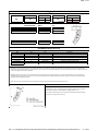
1
Chesapeake College Todd Performing Arts Center Auditorium
Audio System Upgrade
March 20th, 2015
SECTION 27 41 00 - AUDIO SYSTEMS
PART 1 - GENERAL
1.1
RELATED DOCUMENTS
A. Audio System (AV-series) Drawings
1.2
REFERENCES
A. Building Industry Consulting Services International (BiCSi),"Telecommunications Distributions
Methods Manual," Twelfth Edition.
B. Electronic Industries Association/Telecommunications Industry Association (EIA/TIA) -568-C,
"Commercial Building Telecommunications Wiring Standard"
C. EIA/TIA-569-B, "Commercial Building Standard for Telecommunications Pathways and
Spaces"
D. EIA/TIA-606A, “Administration Standard for the Telecommunications Infrastructure of
Commercial Buildings”
E. EIA/TIA-607-A, “Commercial Building Grounding/Bonding Requirements”
F. National Electrical Code (NEC), 2008 - National Fire Protection Agency (NFPA) 70
G. Institute of Electrical and Electronic Engineers (IEEE) 802.3 Carrier Sense Multiple Access
with Collision Detection (Ethernet 100BASE-T)
H. Federal Communications Commission (FCC), Title 47, Code of Federal Regulations, Part 68.
1.3
I.
National Institution for Certification in Engineering Technologies (NICET)
J.
International Communications Industry Association (ICIA).
DEFINITIONS
A. ADA: Americans with Disabilities Act
B. AUD: Audio
C. Bid: Herein, used interchangeably with “proposal”
D. DSP: Digital Signal Processor
E. IR: Infrared
F. NIC: material and work which is Not In Contract and for which the Installer is not responsible
except as otherwise detailed herein.
Audio Systems
27 41 00-1
Chesapeake College Todd Performing Arts Center Auditorium
Audio System Upgrade
March 20th, 2015
G. OFE: “Owner Furnished Equipment” which will be provided by The Owner. Be responsible for
installing and integrating this equipment as detailed herein.
H. OFCI: “Owner Furnished Contractor Installed” Equipment which will be provided by The
Owner. Be responsible for installing and integrating this equipment as detailed herein.
I.
The term “shall” is mandatory.
J.
The term “will” is informative.
K. The term “should” is advisory.
L. Term “provide” means furnish and install.
M. Audio Systems Consultant: Convergent Technologies Design Group, Inc.
N. Bidder: Qualified firm intending to tender a bid on the systems described herein.
O. Owner: Chesapeake College
1.4
BID PROPOSALS
A. Itemized Bid Response
1. Each piece of equipment shall be individually priced and submitted with Bid Proposals.
Provide itemized bid response to include equipment description, manufacturer, model
number, unit price, and quantity on a per room basis. All equipment prices shall reflect
required modifications and accessories as needed for a complete and functioning system.
2. Non-equipment charges shall be outlined separately as a single line item on a per room
basis. A sum of the audio system total cost shall be provided with the bid proposal.
3. Include a separate line item for post-installation warranty service and maintenance visits
specified in this Section, as well as a line item for per-diem cost of any service visits
beyond those specified herein.
B. Contractor Qualification
1. Demonstrate at least three (3) years experience in the fabrication, programming,
assembly, and installation of audio and remote control systems of similar magnitude and
quality as specified for the subject job. Submit documentation to this effect with the bid
response. Be an authorized sales and service center for all listed components and
offerings in this specification.
2. References: Furnish no less than three (3) references for installations of similar size
(dollar amount & quantity of spaces receiving integrated technology) and scope,
performed throughout the Wye Mills, Maryland area within the past three (3) years. At a
minimum, reference information will include the reference company or institute name,
contact person’s name and title, telephone number, address, and detailed project
description, project manager’s name, and contact information of the organization that is
responsible for day-to-day operation of the audio installation.
Audio Systems
27 41 00-2
Chesapeake College Todd Performing Arts Center Auditorium
Audio System Upgrade
March 20th, 2015
C. Alternate Proposals
1. Any proposed alternate equipment choices should be requested in writing by the
contractor prior to the proposal submission for approval. Each item on the alternate
equipment list must be accompanied by catalog cut sheets and technical specifications.
D. Non-Equipment Charges, Including but not be limited to:
1. Engineering: Including all required design drawings, run sheets, instruction manuals,
console layout, step-by-step user guide, etc.
2. Pre-Installation: Work performed on the Installer’s premises including all fabrication,
modification, assembly, rack wiring, etc.
3. Installation: Including all on-site installation and wiring, shop drawing, coordination and
supervision, testing, checkout, Owner training, etc., performed on the Owner’s premises.
4. General and Administrative: Including all shipping, insurance, and guarantees.
E. Owner Furnished Equipment (OFE, OFCI)
1. Identify any Owner Furnished Equipment assumed in the Bid Proposal to be installed and
integrated under this contract. Identify all assumed Owner Furnished equipment within
each room/space type that will be required to complete the Audio systems installation.
F. State of the Art Development
1. Supply only the manufacturer’s latest developed product. In cases where product
development surpasses the criteria of the specification, inform the Architect and make
the newer product available to the project at no additional cost. In no case shall
discontinued or obsolete equipment be acceptable. The same requirement applies to
software programs developed/updated during the warranty period.
2. Should a manufacturer discontinue a specified product, provide the manufacturer’s
recommended replacement at no additional cost to the owner. Should the manufacturer
have no direct replacement product, Audio System contractor shall propose a product of
equal or greater specification from an alternate manufacturer at no additional cost to the
owner.
3. Should a product recall by a specified manufacturer require temporary or permanent
replacement of a product specified under this section, notify the Architect at the earliest
possible time and arrange to replace the product in question as quickly as possible.
a. Equipment found defective or subject to recall prior to scheduled installation shall not
be delivered to the jobsite.
b. Equipment defect or intended recall shall not relieve the Audio Systems Contractor
from any contractual obligations with regard to delivery schedule of product.
c. Under no circumstances shall arrangement for alternate product require the Owner
to accept superseded equipment except on a temporary basis.
G. Service Contract
Audio Systems
27 41 00-3
Chesapeake College Todd Performing Arts Center Auditorium
Audio System Upgrade
March 20th, 2015
1. Submit the costs for a one-year service contract, renewable for up to three years, which
shall commence with the completion of the two-year warranty period. These contracts
shall be fixed-cost, and can be accepted at the option of the Owner.
2. The service contract shall include all of the services provided during the warranty period,
including complete replacement or repair of defective equipment.
1.5
QUALITY ASSURANCE
A. Coordination
1. Specific references, herein, requiring coordination of certain work shall not obviate
responsibility for other required coordination.
B. Standards and Codes
1. Comply with
a. Local, state and federal codes
b. Applicable National Electrical Code
c. American National Standards Institute
d. Underwriters’ Laboratories, Inc. standards.
2. All equipment, material, accessories, and loose items provided by Contractor shall be
new and shall conform to applicable requirements of the above-mentioned agencies.
3. If required by local authorities, provide certificates and labels indicating compliance with
above-mentioned codes and standards where applicable.
C. Point of Contact
1. Designate to the Owner in writing, the responsible person who shall ensure timely and
consistent communication with the Owner on progress of the contract. The designated
representative shall have full knowledge of all engineering and production procedures
and shall report status of the installation and upcoming work plans to the Owner’s
Project Manager and Consultant on a weekly basis.
2. Project manager shall have successfully managed not less than two (2) projects of similar
size and scope (as defined in previous sections). Bid submission shall detail the
percentage of time that the project manager and other key personnel will be involved
with the project.
1.6
SCOPE OF WORK
A. Provide the following in accordance with Specifications and Drawings:
1. All bidding firms must attend a Pre-Bid site walk through and meeting at Chesapeake
College, date to be announced, in order to qualify for bidding on this scope of work.
2. Submittals delivered in a timely manner as described hereinafter.
3. Verification of dimensions and other conditions at project site. Review existing and
specified conduit systems as shown in building construction documents and, where
Audio Systems
27 41 00-4
Chesapeake College Todd Performing Arts Center Auditorium
Audio System Upgrade
March 20th, 2015
applicable, as built conditions. Notify Consultant, Architect, GC, and EC within four weeks
after award of contract of any deficiencies or inadequacies in conduit system design.
4. Detailed design of Digital Signal Processor system “maps,” including remote-control
accommodations.
5. Complete programming of audio processing and remote control system inclusive of
graphical layout and source code programming
6. Power distribution within equipment racks including power connection to electrical outlets
as described in electrical section of building construction documents.
7. Incidentals necessary for a complete working system.
8. Initial testing and adjustments, demonstration of system for approval, participation in
acceptance tests, final adjustments as required.
9. Record Documents, “As-Built” drawings and Owners Manual.
10. Training of operating personnel.
11. Notify appropriate parties of conflicts in a timely manner.
12. Work cooperatively with other trades to resolve conflicts.
B. Special Insurance
1. Provide insurance fully covering all equipment against loss and damage during shipment,
storage, installation, testing, adjustment and demonstration.
1.7
SYSTEM DESCRIPTION
A. Design Intent
1. Provide a complete and functioning Audio system inclusive of all hardware, software and
training to meet or exceed the performance features outlined in this document.
B. Design Standards
1. The Owner’s goal is to have available a cohesive and fully functional system. Therefore,
part of the development efforts for successfully implementing the Audio systems should
include:
a. Install the system in a manner that complies with BiCSi and ICIA cable routing
standards. Route all audio, point-to-point, and remote control cabling elements in a
subtle, unobtrusive manner to maintain the architectural and visual integrity of the
building.
b. Except where plenum cable is used above finished ceilings, it is required that all
cabling be routed inside the comprehensive system of conduit. Floor and wall boxes
shall serve as the primary interface points to the Audio system.
c. Provide and install cover plates, connectors, and associated cabling to link all floor
and/or wall boxes to all affiliated local and remote Audio components. No wiremold
or surface-mounted raceway will be permitted, except where specifically identified on
Audio Systems
27 41 00-5
Chesapeake College Todd Performing Arts Center Auditorium
Audio System Upgrade
March 20th, 2015
d.
e.
f.
g.
h.
i.
drawings. The Audio Systems contractor shall coordinate faceplate materials, colors,
and finishes with the faceplates used by other trades on the project and the architect
to match aesthetics.
Provide and install security covers on any electronics with front panel controls that
should not need to be adjusted after initial set-up. All components permanently
mounted to rack rail systems shall be installed with industry accepted security
screws.
All ceiling mounted Audio equipment shall be secured to building structure. Any
suspended equipment must be mounted with a safety factor of 8. Review existing
structure and provide proposed suspension method for line array loudspeakers with
licensed structural engineer. Include proposed suspension method in submittal
materials.
Steel cable security systems and padlocks to secure structure shall be provided for all
surface mount loudspeakers, and other exposed audio system components. All
padlocks provided for security shall be keyed to a single master key.
Provide intellectual property release and install an editable version of all master
source code for all digital signal processing, remote control or microprocessor-based
systems included on this project to an owner furnished personal computer. Also
provide a hardcopy on portable media.
Provide necessary analog and/or digital audio and control signal repeaters,
extenders, and amplifiers for any run greater than 30 feet and as needed to maintain
required signal levels for receipt at destination device. All audio lines shall be
balanced at the source, prior to any cable pull longer than 20 feet. There are no
exceptions.
For each input/output point of interface to the system, provide a suitable length
patch cord for owner use for every signal type present. Provide umbilical style cable
management for any mobile solutions.
2. Performance Standards: Unless restricted by the published specifications of a particular
piece of equipment, or unless otherwise required, the following minimum performance
standards shall be met by each system:
a. Analog Audio:
1) S/N (including crosstalk and hum):
75 dB minimum
2) Total Harmonic Distortion:
0.5% maximum from 30 Hz to 15,00Hz.
3) Frequency Response:
Flat within +1.0 dB, 30 Hz to 15,000Hz.
b. Performance Test Signal Paths: The signal paths for the above Performance
Standards shall be as follows:
1) Audio: From any and all source inputs (for microphones, audiotape units, etc.)
through all audio processing, audio distribution amplifiers (ADA), mixers,
switchers, codec, etc., to all electrical signal destinations.
c. Remote Control Standards: As a minimum, the remote control system for each space
shall be programmed to include the following:
1) Owner Logo on first page.
2) Automatic System Shutdown.
3) AM/ PM Clock Settings.
4) 50 % audio level default.
5) Separate Program and Microphone Audio Level Control with mute function.
6) Volume/ Mute control for program and speech audio reinforcement on every
screen.
7) Panel layout to include user screens, as well as, password protected technician
pages.
Audio Systems
27 41 00-6
Chesapeake College Todd Performing Arts Center Auditorium
Audio System Upgrade
March 20th, 2015
8) Provide remote control room management software and full licensing for each
system on the project.
9) Full function control of all source components, processing devices and switching
electronics.
10) In sub-dividable spaces, provide both IR and closed contact partition sensor
control, and automation of control system scenerios.
11) Touch panel page layouts shall be submitted for approval. Prior to designing
touch panel layouts, meet with the Owner and review existing control system
standards on campus and determine a basis of design.
12) Follow-up programming and modifications as requested by the Owner shall be
provided 6 months after system acceptance. Provide and install updated editable
source code to the Owner following these updates.
13) In the event the remote control system programming becomes compromised
during the warranty period, provide the necessary effort to make the system fully
functional once again.
3. The specified Audio System shall be ADA compliant through connection to the existing
Assisted Listening System currently installed in the Auditorium. Provide all required
cabling and connections to maintain the current assisted listing system functionality.
1.8
SUBMITTALS
A. Submittal Data
1. Submittal data is to be submitted in a three ring binder, a continuous spiral binder, or
plastic binding that allows the booklet to lie flat while open. Submission of the below
materials in electronic format is also be acceptable. Each booklet shall contain the below
in the following order:
a. Cover Sheet.
1) Include name of supplying contractor and project name.
b. Detailed Bill of Materials.
1) Include a listing of: component quantities, equipment manufacturers, model
numbers, and description of each component being supplied, and the
specification paragraph or drawing sheet that corresponds to the product. Failure
to provide this information will result in the rejection of submittals.
c. Product Data.
1) Include a catalog sheet per product of equipment listed in the Detailed Bill of
Materials, in the exact order as the Detailed Bill of Materials. Each catalog sheet
shall describe mechanical, electrical and functional equipment specifications. The
catalog sheet must also include an image of the product. Photocopy duplications
of the manufacturer’s original equipment catalog sheets will be allowed as long
as they provide adequate clarity of both the printed word and graphics/pictures.
If more than one product is shown on the catalog sheet the intended product
must be denoted by either an arrow or highlight.
d. Authorized Distributor Certificate.
1) Recently dated (within one year from submittal date) support letter from
manufacturer stating that the supplying contractor is an Authorized Distributor of
the product being supplied.
B. Shop Drawings
Audio Systems
27 41 00-7
Chesapeake College Todd Performing Arts Center Auditorium
Audio System Upgrade
March 20th, 2015
1. Prior to fabrication submit contractor generated drawings for approval for all supplied
systems. These drawings shall include, but are not limited to, the following:
a. Title Sheet & Symbols Legend
b. All panels, plates, and designation strips, including details relating to terminology,
engraving, finish and color.
c. All equipment racks, cabinets, consoles, tables, carts, support bases, and shelves.
d. Schematic drawings (Audio & Control Signal Flow), system functional block drawings,
including those for audio subsystems. Resubmission of contract drawings is
unacceptable.
e. All unusual equipment modifications.
f. Front mechanical drawings of each equipment rack.
g. Equipment location drawings.
h. Cable labeling plan.
i. Floor Plans, RCPs and Elevations: Show planned location for all elements and cable
routing. Drawings should be at project standard scale and clearly legible.
j. Mounting and Rigging Details: to be reviewed and stamped by a licensed structural
engineer. As-built documentation of the current building structure is available upon
request.
C. Form
1. Submit all materials for review as described above, specifically referenced to the
Specification paragraph number (where applicable).
a. Submit all drawings on sheets of one size, preferably the project standard size.
b. Where materials are presented on sheets 11” x 17” or smaller, organize into threering binder which include:
1) Dividers or tabs between logical sections
2) Project name and binder title labels on face and edge of binders
c. On submittal drawings, maintain 3/32” minimum lettering height. Submittals with
text less than 1/16” in height may be rejected.
2. Partial Submittals may be rejected. If submitted individually and each in its entirety, the
following Submittals shall not be considered partial:
a. Personnel
b. Milestones
c. Conduit Verification Statement and Notifications
d. Rigging and Mounting Drawings
e. As-Built Documentation
3. Product Data and Shop drawings must be submitted together in order to be reviewed.
D. User Interface
1. In order to develop a user interface which is both functional and useable, provide
working “Beta” copies of system software for review and comment by the owner,
architect and the Audio System consultant as per the below listed schedule:
a. This is anticipated to be an interactive process, requiring at least three submittals
prior to first beneficial use. At a minimum, the software development process will
have the following milestones:
1) Initial concept Submittal for Review
2) First Beta Review
3) Second Beta Review
Audio Systems
27 41 00-8
Chesapeake College Todd Performing Arts Center Auditorium
Audio System Upgrade
March 20th, 2015
4) Final Implementation and On-Site Training: Prior to Final Acceptance
5) Follow-up programming review and updates; Timing (within sixty-days from final
acceptance)
E. Weekly Reporting
1. Commencing with project award, provide weekly status reporting of milestone task
status, anticipated completion date, and related memo notes for the following tasks:
a. Submittals
b. Infrastructure verification
c. Pre-wire status
d. Equipment Procurement
e. Shop fabrication
f. Remote control system design
g. Installation and Terminations
h. Field testing and pre-acceptance testing
i. Final acceptance demonstrations
j. Owner training
k. First owner use
l. Open Coordination Items and Questions
2. See below for a partial example of an acceptable weekly reporting list.
Project: Project Name
Location: Project Location
Project Manager:
Project Manager
Date: Form Delivery Date
Delivered by: Form Delivered By
Projected Completion:
Status:
6/1/2011
Complete
Product Data
Drawings
Personnel (etc.)
8/1/2011
8/1/2011
8/1/2011
Complete
Complete
Complete
12
178
8/25/2011
9/6/2011
Received
Pending
Infrastructure Verification:
Submittals:
Notes:
RFIs:
Installation Status by Space
Room
Name
Number Pre-Wire
Equipment
Order
Receive
Install
Test
Example 1
Example 2
100%
100%
60%
90%
0%
0%
105
135
100%
100%
100%
100%
Implementing
Projector Screen Clearances
Notes:
Re-programming
Other Notes Here
F. Personnel
Audio Systems
27 41 00-9
Chesapeake College Todd Performing Arts Center Auditorium
Audio System Upgrade
March 20th, 2015
1. Provide, in writing, within two weeks after award of Contract, the names, mailing
address, phone numbers with extensions, email addresses and paging service numbers
(if available) of the following project personnel:
a. Project Manager
b. Lead Systems Engineer
c. Field Foreman
d. Remote Control System Programmer
G. Conduit Verification
1. Within four weeks after award of Contract, submit statement confirming that Contractor
has reviewed the conduit system as designed in building construction documents and,
where applicable, as built.
2. Notify Consultant, General Contractor, Architect or Electrical Contractor of deficiencies or
inadequacies, if any, in conduit system design or installation. If none, so indicate.
3. Absent conduit verification by Contractor and after installation of conduit as designed,
Contractor shall assume costs of equipment, materials, labor and engineering, including
services of owner’s representative(s) in designing and/or verifying revised wiring
approach(es) as relate to providing a fully functional system using conduit as designed or
as revised at the discretion of the owner.
H. Rigging and Mounting Drawings
1. Submit full size drawings outlining mounting and installation details of all Audio
equipment requiring integration with cabinetry or architectural elements.
2. Details, stamped and signed by an appropriately licensed engineer, of all equipment
mounting methods and materials provided by the Scope of Work, wherein failure of
method or materials used for mounting or hanging permanently installed equipment
could result in serious personal injury.
a. Details provided by or requiring approval by licensed engineer may include: method
of attachment to building structure or attachment and/or suspension points; method
of attachment to supported equipment; all suspension materials; a materials list
including specifications of all suspension materials; calculations used to determine
loads and strengths of suspension materials, other as deemed necessary by the
engineer.
3. In the absence of submitted approved, stamped and signed mounting and hanging
details, the Owner reserves the right to acquire such engineering approval at the
expense of the Contractor. Owner will notify Contractor of such intent. Contractor shall
remedy within two weeks or Owner may proceed without Contractor approval and
without relieving Contractor from any other obligations set forth by Contract.
I.
Color Selection
1. Color options for all items as applicable.
2. Wallplate finishes should be coordinated with the Owner.
J.
Samples
Audio Systems
27 41 00-10
Chesapeake College Todd Performing Arts Center Auditorium
Audio System Upgrade
March 20th, 2015
1. Color and finish samples of any visible components.
1.9
CLOSEOUT SUBMITTALS
A. At the completion of the installation, but before Final Acceptance, provide for review and
approval the following:
1. Operation and Maintenance Manuals:
a. Equipment manufacturer’s operation and service manuals for each make and model
of equipment.
b. System Operation Manual. Produce a manual specifically for the subsystems detailed
herein. The manual shall describe all procedures necessary to activate each system
to provide for the functional requirements, except as specifically excluded by the
Owner. This section shall provide a simple “How-to” users guide for the procedures
needed to operate the system. This document shall contain a section on operating
the systems equipment in the event of control system failure. Control system touch
panel layouts shall be accompanied by narrative text describing “step-by-step”
function engagement.
2. Warranty
a. Provide list and dates of activation of equipment warranties
b. Provide original manufacturers’ certificates.
3. As-built Drawings
a. Include contractor generated (mark-up of contract documents is not acceptable)
digital record diagrams for all systems including, but not limited to:
1) Schematic wiring diagrams with cable markings.
2) Internal wiring diagrams of the equipment rack cabinets.
3) Custom equipment modifications.
4) Final test results and nominal settings for all adjustable controls.
4. Software Passwords
a. Software Passwords Schedule (i.e., a spreadsheet listing the manufacturer, model
number and location in the Facility, of each piece of audio equipment, the software
for which is password-protected).
b. Provide to Owner’s Representative as a secure document separate from Operating
and Maintenance Manuals and As-Built Drawings.
5. Editable Control System Code
a. Provide the final control system code in an editable format.
6. Laminated Instruction Cards
a. Provide 8 ½ x 11 Instruction cards, approved by the Owner. Laminate step-by-step
instructions outlining system operations for each room that has an Audio system.
Provide editable file of card to Owner.
7. Existing Equipment
a. Provide to Chesapeake College all existing loudspeakers and electronics removed
during this scope of work. Provide an itemized spreadsheet identifying each existing
piece of equipment provided to Chesapeake College, including quantities,
manufacturer, and model number.
Audio Systems
27 41 00-11
Chesapeake College Todd Performing Arts Center Auditorium
Audio System Upgrade
March 20th, 2015
1.10
DELIVERY, STORAGE, HANDLING, AND STAGING
A. Supply, transport, deliver, unload, move to the installation location, unpack, place, assemble,
secure, connect, and install all equipment needed to complete the installation. Be
responsible for transportation, parking, delivery, and on-site storage of the system’s
equipment. Be responsible for all transportation of personnel to and from the site.
B. Reconfirm before delivery that hallways, stairways, passages, doorways, rooms, entries,
elevators and foyers are of sufficient size to accommodate the passage and installation of the
equipment and systems. Off-site pre-staging of goods is encouraged.
C. The Owner’s acknowledgment of delivery of goods and any payment made on account of
such delivery shall not constitute acceptance (partial or otherwise) and shall not diminish
obligations as specified.
D. The actual dates of delivery shall be under the absolute control of the Owner. The dates and
times for delivery/installation are critical to the successful completion of the project.
Deliveries shall normally be accepted only Monday through Friday 8:00 a.m. to 4:00 p.m. In
the event it becomes necessary for goods to be installed outside these hours comply with the
instructions of the Owner. Deliveries attempted outside these hours without prior consent of
the Owner may be turned away. Comply with all instructions of the Owner and the
Contractor concerning time of arrival at the site; which entrance shall be utilized for delivery;
routes to be taken to reach the installation location; and other matters relating to the orderly
and timely installation of the system.
E. Installation shall commence immediately upon delivery of materials to the jobsite, except as
directed by owner. Time required from delivery date to completion of project shall be in
accordance with the approved schedules.
1.11
SYSTEM TRAINING
A. Training: Provide training in the operation and maintenance of the system for personnel
designated by the Owner. Record owner training sessions on DVD or other agreed upon
media, and make training videos available to the owner at no charge. The training shall be
organized as follows:
1. Two (2) four-hour training classes for system technical operation and maintenance. This
class shall cover the following topics:
a. Review of signal flow diagrams.
b. Review of all equipment functions, relevant to the function in this system.
c. Review of initial equipment settings.
d. Demonstration of all functional connections from a user perspective.
e. Review & demonstration of replacement procedures for consumables.
f. Review of manufacturers’ recommended routine maintenance procedures.
2. Two (2) four-hour training classes for system engineering concerns. This class shall cover
the following topics:
a. Review of signal flow diagrams.
b. Review of all equipment functions, relevant to the installation.
c. Review of initial equipment settings.
d. Review of manufacturer’s recommended routine maintenance procedures.
e. Review & demonstration of replacement procedures for consumables.
Audio Systems
27 41 00-12
Chesapeake College Todd Performing Arts Center Auditorium
Audio System Upgrade
March 20th, 2015
f.
Review & demonstration
procedures.
of
control
system
software
replacement/upgrade
3. Two (2) four-hour training classes addressing Audio system operations. The classes will
demonstrate and describe the following:
a. System set-up and operations.
b. Control system operation.
c. How to attach microphones, record Audio signals, and control the sound system.
d. Audio monitoring system operations.
e. Provide and coordinate at least two (2) technical visits by Yamaha and Bose
separately to assist in tuning the audio system & system training, along with two (2)
additional visits from each manufacturer during the first public uses of the system.
Dates and times of public uses or performances for which manufacturer
representatives must attend are to be determined by and coordinated with
Chesapeake College. Total hours in system tuning and training visits must be at a
minimum, sixteen hours (16) for Bose representatives, and eight (8) hours for
Yamaha representatives.
f. Contact Bose directly to David Andrews at 717-738-3828
4. Training may take place at any time (chosen by the Owner) after the systems are
operational, up to a year following system acceptance.
5. Close out submittals shall be provided prior to any training classes.
6. Coordinate detailed specifics of the training session(s) time, date & location with the
Owner.
1.12
WARRANTY
A. The system warranty shall be for twenty-four (24) months from the date of final acceptance.
Provide all equipment, material, and labor required to uphold a full system warranty at no
charge to the Owner. All manufacturers’ equipment warranties shall be activated in the
Owner’s name and shall commence on the date of final acceptance. In the case of modified
equipment, the manufacturer’s warranty is normally voided. In such cases, provide the
Owner with a warranty equivalent to that of the original manufacturer.
B. Include in overall systems warranty, a service warranty for all existing hardware which is to
be re-used in the final installed system.
C. There shall be no cost to the Owner for maintenance performed during the warranty period
beyond the fixed cost of the contract.
D. Coordinate and provide updates to the control system code & touch panel layouts based on
owner feedback of desired functionality during warranty period.
E. Provide a total of four (4) one-day visits per year, or a total of thirty-two (32) engineering/
service labor hours to conduct preventive maintenance and the Owner directed system
adjustments. Include pricing for these maintenance visits as an add-alternate in the
submitted bid proposal.
F. Each visit will include:
Audio Systems
27 41 00-13
Chesapeake College Todd Performing Arts Center Auditorium
Audio System Upgrade
March 20th, 2015
1. Checking and repairing microphones and microphone cables.
2. Conducting subjective and objective tests of the audio and control systems of the
installed audio systems.
G. Repair and/or adjust any malfunctioning components located by the technician during this
testing. Include control system programming updates and modifications as part of this
service contract, providing an updated editable copy of the source code to the Owner.
H. Provide a service telephone number, staffed by a qualified technician familiar with the
equipment installed. Staff this number during normal business hours.
I.
Respond with an on-site technician within 24-hours of a service call (including Saturdays and
Sundays) for all equipment and system failures.
J.
Replace or repair, at no cost to the owner, any failed equipment hardware or software
installations required to provide full system operations.
K. During the warranty period, advise the Owner in writing each time any routine software and
firmware updates become available, giving the Owner the opportunity to upgrade the
software/hardware should they so desire at no additional cost. Provide any necessary system
modifications after installation of these updates to maintain a fully functioning system.
L. Provide updates to firmware during service period. Provide any necessary system
modifications after installation of these updates to maintain a fully functioning system.
PART 2 - PRODUCTS
2.1
PRODUCTS AND MANUFACTURERS
A. Equipment Lists: Included below is a list of all equipment and materials required to complete
the work of this section, for reference.
1. Music, Announcement, and Audio Effect Module
a. Stereo audio input and output
b. 16/24 bit digital audio conversion
c. More than 250 hours recording capability
d. Provide quantity of one (1)
Product: 360 Systems Instant Replay 2, or approved equal
2. Personal Performance Monitoring System (Add Alternate Only)
a. One (1) RJ45 A-Net signal input
b. Recieves 16 discrete channels of audio over single Category cable
c. Headphone output with personal mix controls
d. Provide Bose SoundTrue in-ear headphones for ½ of all units
e. Provide Sony MDR-V600 headphones for ½ of all units
f. Provide stand
g. Provide all required patch cabling
Product: Aviom A320, or approved equal.
Audio Systems
27 41 00-14
Chesapeake College Todd Performing Arts Center Auditorium
Audio System Upgrade
March 20th, 2015
3. Centralized Audio Signal Distribution Module (Add Alternate Only)
a. One (1) RJ45 A-Net signal input
b. Eight (8) RJ45 simultaneous split A-Net signal outputs
c. Rack mountable
d. Provide all required patch cabling
Product: Aviom D800, or approved equal.
4. 16-Channel Monitoring System Input Module (Add Alternate Only)
a. 16 balanced inputs – ¼” TRS connectors
b. 16 balanced thru connectors TRS
c. A-Net Out and A-Net Expansion network connections (RJ45)
d. Stereo link switches for each pair
e. Four position gain switches
f. Signal present and clip LEDs per channel
g. 1RU
Product: Aviom AN-16/I v.s, or approved equal.
5. Configurable Audio Power Amplifier
a. 20 Hz to 20 kHz Frequency Response
b. 102 dBA Signal to Noise Ratio
c. Eight (8) audio input channels
d. Two to Eight (2 – 8) audio output channels
Product: Bose PM8500.
6. Central DSP Audio Processor
a. Rack Mountable, 2 RU
b. 20 Hz – 20 kHz frequency response
c. 24-bit A/D conversion
d. Provide Bose Audio Input Cards EDR4-I
e. Provide Bose Audio Output Cards EDR4-O
Product: Bose ESP-00.
7. RoomMatch Dual 15” Subwoofer
a. Frequency Range 40 Hz – 280 kHz
b. Dual 15” drivers
c. 1000 Watt Power Handling
d. 2x 8 ohm inputs
e. Refer to the attached Bose Room Match Array Rigging Data document. Provide all
part numbers identified in this document, and comply with recommended mounting
details.
f. Reference Bose quote number US112301ChesapeakeCollege
Product: Bose RMSS215.
8. Suspended Loudspeaker Line Array
a. Frequency Response: 60 Hz – 16 kHz
b. Dispersion Pattern: 120 x 20 degrees
c. 4 ohm low frequency input
Audio Systems
27 41 00-15
Chesapeake College Todd Performing Arts Center Auditorium
Audio System Upgrade
March 20th, 2015
d. 8 ohm high frequency input
e. Provide RMSFLY line array suspension array, RMAFLG Frame, and RMXSRT Extension
f. Integrate this device, RM120x10, and RMS215 into a single suspended line array
system
g. Refer to the attached Bose Room Match Array Rigging Data document. Provide all
part numbers identified in this document, and comply with recommended mounting
details.
h. Provide quantity of one (1)
i. Reference Bose quote number US112301ChesapeakeCollege
Product: Bose RM 120x20.
9. Suspended Loudspeaker Line Array
a. Frequency Response: 60 Hz – 16 kHz
b. Dispersion Pattern: 120 x 10 degrees
c. 4 ohm low frequency input
d. 8 ohm high frequency input
e. Provide RMSFLY line array suspension array, RMAFLG Frame, and RMXSRT Extension
f. Integrate this device, RM120x10, and RMS215 into a single suspended line array
system
g. Refer to the attached Bose Room Match Array Rigging Data document. Provide all
part numbers identified in this document, and comply with recommended mounting
details.
h. Provide quantity of three (3)
i. Reference Bose quote number US112301ChesapeakeCollege
Product: Bose RM 120x10.
10. Stage Fill Loudspeakers (Stage Fill)
a. Frequency Response 80 Hz – 16 kHz
b. 90 x 60 degree dispersion
c. 94 dB Sensitivity
d. Provide stands for temporary use as stage fill loudspeakers
e. Provide all infrastructure required to connect loudspeakers to stage fill output plates
at face of stage
Product: Bose RMU-208.
11. Stage Monitor Loudspeaker
a. Floor-wedge style stage monitor
b. 100 watt power handling
c. 8 Ohm input
Product: Bose Panaray 310M.
12. Ceiling Mounted Pre-Function Area Loudspeakers
a. Frequency Response: 60 Hz – 18 kHz
b. 200 watt continuous power handling
c. 97 dB Sensitivity
d. Mount in ceiling above Pre-Function area. Remove all existing loudspeakers, clean,
and furnish to Chesapeake College prior to installing specified loudspeakers.
e. Provide acoustically transparent grille, white in color
Audio Systems
27 41 00-16
Chesapeake College Todd Performing Arts Center Auditorium
Audio System Upgrade
March 20th, 2015
f.
Provide manufacturer recommended rear loudspeaker enclosure
Product: Community Cloud1266, or approved equal.
13. Remote Control Touch Panel Interface (Add Alternate Only)
a. 8” Color Touch Screen Display
b. Wireless Communications
c. Provide Docking Station for use in Control Room
Product: Crestron TPMC-8X-GA, or approved equal.
14. Remote Control Processor
a. Rack Mountable, 1 RU
b. Core 3 Operating System, 32-Bit
c. Transmits Ethernet, RS-232 control signals
d. Provide programming for Xpanel integration, with iPad tablet.
Product: Crestron CP3, or approved equal.
15. Wireless Intercom Base Station
a. Frequency Range: 2400 – 2483.5 MHz
b. Frequency Response 200 Hz to 3.5 kHz
c. 600 ohm 4-wire input/output
d. External dual diversity ½-wave dipole antenna
e. Provide all required batteries and chargers for associated belt packs
f. Provide Four (4) Clear-Com BP-210 Wireless Beltpacks, with CC-400 headsets
Product: Clear-Com BS-121, or approved equal.
16. Production Intercom Master Station
a. 4-Channel Master Station
b. Provide Clear-Com CC-400 headset and faceplate microphone
c. Provide Clear-Com HB-702 wall plate station at 4-gang existing box backstage
d. Provide four (4) model RS701 wired beltpacks and associated headsets
Product: Clear-Com MS-704, or approved equal.
17. 8-Port Unmanaged PoE Network Switch
a. Eight (8) RJ45 10BASE-T / 100BASE-TX ports
b. 3.2 Gbps Switching Capacity
c. 2.4 mpps Forwarding Capacity
d. 2RU
e. PoE enabled
Product: Cisco SRW208P-K9-NA, or approved equal.
18. 16
a.
b.
c.
d.
Audio Systems
Channel Dante Audio Interface
16 balanced audio inputs on two (2) DSUB 25-pin connectors
16 balanced audio outputs on two (2) DSUB 25-pin connectors
One (1) Ethernet output on female RJ-45 jack
Distributes multi-channel audio information over LAN connection to dante-enabled
devices
27 41 00-17
Chesapeake College Todd Performing Arts Center Auditorium
Audio System Upgrade
March 20th, 2015
e. 20 Hz – 20 kHz Frequency Response
Product: Focusrite Rednet-2, or approved equal.
19. 82”
a.
b.
c.
d.
e.
f.
Tall Equipment Rack (2nd floor Equipment Rack)
45 RU
81 1/8” overall height; 25” overall depth; 22” overall width
Provide security screws
Provide quiet exhaust fan top 4”
Provide RSH series rack mount kits as needed
Provide Furman PL-Pro D II power distribution
Product: Middle Atlantic BGR-4525, or approved equal.
20. 1st
a.
b.
c.
d.
e.
Floor Control Room Equipment Rack (Base Option)
35 Rack Units
Wall Mount, Swing-out cabinet
15” overall center section depth
Provide Security Screws
Provide pricing as Base Option with Marshall Furniture MEQ-70R as Add Alternate
Product: Atlas 335-15, or approved equal.
21. Custom Equipment Cabinet (1st floor Control Room, Add Alternate)
a. Reference Marshall Furniture Quote number MFI-29505AB
b. 36 Total Rack Units, with Front and Rear rack rails
c. Two (2) locking wood frame doors with smoked plexi glass windows
d. Three (3) 3” grommets in top surface
e. Natural maple finish
f. Provide Security Screws
g. Provide quiet 4” exhaust fan
h. Provide Pricing as Add Alternate option
Product: Marshall Furniture MEQ-70R, or approved equal.
22. Mobile Equipment Rack (Backstage)
a. 18 Rack Units
b. Provide Casters and Locking Door
c. 500 Lbs load capacity minimum
d. Provide Security Screws
Product: Anvil Castered Rack Case, or approved equal.
23. Gooseneck Microphone
a. 18” gooseneck electret condenser microphone
b. Frequency Response: 50Hz to 17kHz
c. Cardioid cartridge
d. Shock mount, flange mount, windscreen
e. Mute switch and LED
Product: Shure MX418S/C, or approved equal.
Audio Systems
27 41 00-18
Chesapeake College Todd Performing Arts Center Auditorium
Audio System Upgrade
March 20th, 2015
24. 4-Channel Wireless Microphone System
a. 1RU Rack Mountable Wireless Receiver
b. Four discrete output channels, XLR connectors
c. Switchable mic/line output levels
d. Removable ½ wave antennas
e. Provide remote antennas to enable coverage of vestibules 102a and 104a
f. Provide Shure MX150 lapel microphone
g. Provide Shure ULXD1 bodypack transmitter
Product: Shure ULXD4Q, or approved equal.
25. 48-Point Audio Patch Panel
a. 24x24 Line-Level audio patch panel
b. No normalled connections
c. ¼” TRS female jacks
d. Rack mountable, 1 RU
e. Provide patch cables for all input and output points
Product: Switchcraft MT48K1HN, or approved equal.
26. 32-Point Microphone Audio Patch Panel
a. 16x16 microphone level audio patch panel
b. XLR female jacks
c. Rack mountable, 2 RU
d. Provide XLR-to-XLR and XLR-to-1/4” patch cords for all input and output points
Product: Switchcraft QGPK3B440, or approved equal.
27. Compact Flash Audio Recorder
a. Solid State recording to Compact Flash media
b. 1 RU
c. Records in WAV or MP3 format to CF Card
d. Balanced XLR and unbalanced RCA input/output connections
e. RS232 controllable
Product: Tascam SS-R1, or approved equal.
28. Powered Studio Monitors
a. Integral amplification circuitry
b. TRS and XLR line input connectors
c. Provide quantity of two (2)
Product: Tannoy Reveal 402, or approved equal.
29. 8-Channel Microphone Preamplifier
a. 8 input microphone level on XLR connectors
b. 8 line outputs
c. Rack mountable, 1 RU
d. 20 Hz – 20 kHz frequency response
Product: True Systems Precision 8, or approved equal.
Audio Systems
27 41 00-19
Chesapeake College Todd Performing Arts Center Auditorium
Audio System Upgrade
March 20th, 2015
30. Audio Mixing Console
a. Thirty-Two (32) microphone inputs
b. Two (2) YGDAI expansion slots
c. Provide Yamaha MY8-DA96 input card
d. Provide Yamaha MY8-AD96 output card
e. Dante Audio Interface (Primary and Secondary)
f. Provide programming for remote control via iPad, and provide Apple iPad, quantity of
one (1), to be 64GB memory with retina display and grabbit protector case.
g. Provide iPad Docking Station
h. Provide Add Alternate Pricing for Yamaha CL5 audio mixer in lieu of the specified
QL5, inclusive of all accessories noted here
Product: Yamaha QL5.
PART 3 - EXECUTION
3.1
INSTALLATION
A. General:
1. All existing loudspeakers and associated hardware which is removed from the existing
facility shall be cleaned, salvaged, and furnished to Chesapeake College for storage and
future use. Coordinate delivery of existing hardware with Chesapeake College.
2. All installation work shall be in accordance with, but not limited to, this specification and
drawings. Work practices shall be performed in accordance with applicable standards,
requirements, and recommendations of Federal and Local authorities having jurisdiction.
3. All discrepancies discovered and any discrepancies which are apparent at the date of
submission of bids, shall be immediately corrected without additional charge to the
Owner.
4. Clearly label all user controls for intended use and nominal setting. These labels shall be
engraved and filled, or equal. Note: “Dymo” labels are not acceptable.
5. All equipment to be rack mounted shall be supplied with the appropriate rack mount kits.
6. Each rack enclosure shall have a single button on/off power distribution panel to include
pull out lights and LED voltage indicator (Furman PL-Pro DMC or equal) located in the
first available rack unit.
7. All equipment racks to include removable, locking front doors and a 4” diameter, lownoise fan.
8. All rack and instructor stations shall include “security type” screws to secure rackmounted components.
9. In rooms containing wireless microphones or assisted listening system, provide an
antenna distribution system inclusive of remote antennas as needed to support
transparent coverage throughout the space(s).
B. Physical Installation:
Audio Systems
27 41 00-20
Chesapeake College Todd Performing Arts Center Auditorium
Audio System Upgrade
March 20th, 2015
1. Provide system identification plate as shown below. Plate shall occupy the first available
rack unit in all Audio System equipment racks. If more than two (2) racks are positioned
together, one (1) plate for every two racks is acceptable. Product: Covid # 1R0001-BA-XA-CT.
2. All equipment shall be firmly secured in place unless requirements of portability dictate
otherwise. Unless granted specific permission by the Owner, install and secure all boxes,
equipment, etc., plumb and square.
3. Fastenings, mounting brackets and supports shall be adequate to support their loads
with a safety factor of at least eight (8). A safety chain or cable will be tied to all
equipment suspended from above.
4. In the installation of equipment and cable, consideration shall be given not only to
operational efficiency, but also to overall aesthetic factors.
3.2
AUDIO CABLE INSTALLATION
A. All cables, regardless of length, shall be marked with wraparound cable markers at both
ends. There shall be no unmarked cables at any place in the system, inclusive of existing
cabling to be re-used. Marking codes used on cables shall correspond to codes shown on
“as-built” drawings and/or run sheets. The labeling and numbering system will be
coordinated with the Owner.
B. All wired microphones shall include a 30ft. patch cable with heavy-duty jacket and XLR
connectors.
C. Loudspeakers operating at 8 ohms shall be installed with 12AWG cable as a minimum size/
diameter. Confirm existing cabling to be re-used meets this standard.
D. Wall plate and floor box input/output panels shall be installed with audio line drivers on runs
exceeding 35ft.
E. All cabling shall be neatly strapped, dressed, and adequately supported.
cabling shall be neatly enclosed in a protective covering.
Any exposed
F. Terminal blocks, boards, strips, or connectors shall be furnished for all cables, which
interface, with racks, cabinets, consoles, or equipment modules.
G. All audio signal lines shall be balanced at I/O plates. Provide ninety (90) degree connector
adapters for all Audio cabling at custom I/O plates.
H. All cables shall be grouped according to the signals being carried. In order to reduce signal
contamination, separate groups shall be formed for the following cables:
1. Power cables
2. Control cables
Audio Systems
27 41 00-21
Chesapeake College Todd Performing Arts Center Auditorium
Audio System Upgrade
March 20th, 2015
3. Data cables (when applicable)
4. Audio cables carrying low level signals
5. Audio cables carrying line and high level signals
I.
Supply cables as required to meet system performance standards. Any cabling installed in
walls or ceilings shall be plenum rated. All cables shall be cut to the length dictated by the
run plus the required service loop to permit future equipment movement and relocation. For
equipment mounted in drawers or on slides, the interconnecting cables shall be provided with
a service loop of appropriate length.
J.
No cable shall be installed with a bend radius less than that recommended by the cable
manufacturer. Notify the construction manager in the event that a field condition interferes
with the proper installation of any cables or equipment.
K. Grounding Procedures: In order to minimize problems resulting from improper grounding
and to achieve maximum signal-to-noise ratios, the following grounding procedures shall be
adhered to:
1. General: Because of the great number of possible variations in grounding systems, follow
good engineering practice, as specified herein, and to deviate from these practices only
when necessary to minimize crosstalk and to maximize signal-to-noise ratios in the audio
and control systems. Inform the Consultant in the event that there is a deviation from
the standard grounding practices prior to actually performing the work.
2. System Ground: A single “system ground” shall be established for the system. All
grounding conductors shall connect to this system ground. The system ground shall be
provided in the equipment rack, and shall consist of a copper bar of sufficient size to
accommodate all secondary ground conductors.
3. A copper conductor, having a maximum of 0.1 Ohms total resistance, shall connect the
system ground bar to the nearest grounded, metallic electrical conduit of at least 2
inches in diameter. Be responsible for determining if the metallic conduit is properly
electrically bonded to the building ground system, and shall show the grounding path of
a document that is provided with the system documentation.
4. Secondary system grounding conductors shall be provided from all ungrounded
equipment in each area, to the primary system grounding point for the area. Each of
these grounding conductors shall have a maximum of 0.1 Ohms total resistance.
5. Under no conditions shall the AC neutral conductor, either in the power panel or in a
receptacle outlet, be used for a system ground.
L. Audio Cable Shields: All balanced audio cable shields shall be grounded at one point only.
For ungrounded portable equipment, such as microphones, the shield shall be connected at
both ends but grounded at only one end.
M. Non-continuous cable supports
1. Audio cables shall be supported AFC with adjustable non-continuous cable supports,
where not routed through conduit.
Audio Systems
27 41 00-22
Chesapeake College Todd Performing Arts Center Auditorium
Audio System Upgrade
March 20th, 2015
2. Non-continuous cable supports shall provide a bearing surface of sufficient width to
comply with required bend radii of audio cables.
3. Non-continuous cable supports shall have flared edges to prevent damage while installing
cables.
4. Installation and configuration shall conform to the requirements of the current revision
levels of ANSI/ EIA/TIA Standards 568 & 569, NFPA 70 (National Electrical Code),
applicable local codes, and to the manufacturer’s installation instructions.
5. Do not exceed load ratings specified by manufacturer.
6. Follow manufacturer’s recommendations for allowable fill capacity for each size noncontinuous cable support.
7. Non-continuous cable supports shall be ERICO CableCatTM J-hook series or approved
equal.
3.3
REPAIR/RESTORATION
A. Any damage to any installed work or product caused by the unpacking, transporting,
assembly, connecting, or configuring of the product shall be repaired at no charge to the
Owner.
3.4
FIELD QUALITY CONTROL
A. Once installed and the System Checkout is complete, the system shall be demonstrated as
operational to the Owner.
1. If the Audio system fails to meet the requirements of this document or those stated by
the technical documentation, then the Owner shall reject the installed system and the
contractor shall be given notice (either oral or in writing) to correct the failure.
2. If unable to overcome repeated performance deficiencies within thirty (30) days, and if
requested to do so by the Owner, remove the equipment and replace at no expense to
the Owner.
3. No warranties shall begin until the Owner has authorized final acceptance in writing.
4. Right to Revoke Acceptance: If any equipment and/or goods which have been previously
accepted, specifically or by the making of payment, are found to have defects, damage,
deficiencies, or fail to conform to the specification, for any cause not attributable to the
Owner, the Owner may revoke acceptance.
B. Conduct pre-acceptance tests
1. Perform all system performance checks on the installed systems prior to final acceptance
testing. The Owner / Audio Consultant, may witness the pre-acceptance tests. The
Owner / Architect may inspect and operate system components in order to evaluate
installation progress and technical compliance prior to acceptance testing.
C. Contractor System Checkout
Audio Systems
27 41 00-23
Chesapeake College Todd Performing Arts Center Auditorium
Audio System Upgrade
March 20th, 2015
1. Perform system checkout before acceptance tests are scheduled. Furnish all required
test equipment. Perform all work necessary to determine and/or modify performance of
the system to meet the requirements of this specification.
2. During performance testing, all equipment shall be operated under standard conditions
as recommended by the manufacture.
3. Test all audio systems for compliance with the Performance Standards using test
procedures that follow later in this specification.
4. Maintain documentation of all performance tests for reference by Consultant during the
System Acceptance Tests.
5. At the conclusion of the tests, return all equipment settings to previously calibrated
positions.
6. Provide written records of all test results in spreadsheet form.
7. Check all control functions, from all controlling devices to all controlled devices, for
proper operation.
8. Adjust, balance, and align all equipment for optimum quality and to meet the
manufacturer’s published specifications. Establish and mark normal settings for all level
controls, and record these settings in the “System Operation and Maintenance Manual.”
9. Provide testing results and settings for all equipment and systems to the Consultant at
least three (3) business days prior to System Acceptance Testing.
10. Provide the Audio Consultant with all test results, manuals, software, as-built
documentation, etc. prior to acceptance testing.
11. Inform the Owner and Audio Consultant that the systems are ready for System
Acceptance Testing by the Consultant. The system shall be considered ready for
acceptance testing when the following conditions are met:
a. Audio System Contractor has pre-tested all systems such that all sub-systems,
functions, software, and equipment are de-bugged and operational
b. Audio System Contractor has supplied the Audio System Consultant with the written
test results and documentation as listed above for all rooms and systems
c. Audio System Contractor has supplied the Audio System Consultant with close out
(manuals, training materials, and other as-built) documentation revised to reflect
comments and/or revisions arising from the review cycles listed elsewhere within this
document
12. Should the systems not be ready for testing by the Audio System Consultant at the
date(s) and time(s) indicated by the Audio Contractor, system acceptance testing may be
rescheduled at the sole discretion of the Audio Systems Consultant. Pay for the labor
and expenses of the Audio Consultant and other project team members assembled at the
project site for the purpose of system acceptance testing for the date(s) of the original
scheduled testing plus the labor and expenses of the Audio Consultant and other project
team members for the rescheduled testing date(s). The labor rate for the Audio
Consultant shall be a flat rate of $200.00/hour including travel time. Other project team
member labor costs shall be at their respective published rates. The PM and/or Owner
Audio Systems
27 41 00-24
Chesapeake College Todd Performing Arts Center Auditorium
Audio System Upgrade
March 20th, 2015
shall be entitled to deduct any money owed to the Owner, PM, Audio Consultant, or
other project team members under this contract from any sum which may become due
or is payable to the Audio Contractor under this Contract for the purposes of satisfying
the charges listed above.
D. Final Acceptance Test
1. Testing will be performed with the Owner (or its designees) present to determine that
the Audio system equipment satisfies the manufacturers’ performance specifications and
that the Audio system installed satisfactorily performs the functions required by this
specification. Conduct formal pre-acceptance tests prior to the Owner’s acceptance
testing to ensure that the performance and functional specifications are satisfied by the
installed system and the system is ready for the Owner’s acceptance. Verify in the
owner’s presence that the installed audio system satisfies the performance and functional
requirements through formal acceptance testing. Be responsible for staging each room to
be tested, and shall have sufficient personnel on site to run multiple systems at once (not
less than three (3) personnel).
E. Test Equipment
1. Assemble the following test equipment (or equivalent) on site.
a. Audio and control cable, terminations, adapters, etc
b. Audio Test CD
c. DVD
d. Programmable Audio Test Generator, Extron VTG-400D
F. Audio System Testing
1. Absolute Impedances
a. Set any speaker level controls at zero attenuation. Measure absolute impedance
value of each speaker line at 250, 500, 1000, 2000, 4000 Hz without the amplifier
connected but with all speakers connected. Impedance must not be below the rated
load impedance of respective amplifier and may be any value equal to or above that.
Check resistance of lines to all speakers and microphone receptacles with receptacles
open and short-circuited.
2. Hum and Noise Level
a. Test overall hum and noise, it should be at least 60 dB below rated power output of
each amplifier with amplifier controls set for optimum signal to noise and full output
and with inputs terminated with proper shielded resistor. (150 and 600 ohms).
3. Parasitic Oscillation and RF Pickup
a. Set up system for each specified mode of operation.
b. Use 5 MHZ band with oscilloscope and speaker monitoring.
c. Check to insure that the system is free of spurious oscillation and RF pickup in the
absence of any input signal and also with the system driven momentarily to full
output at 160 Hz.
4. Buzzes, Rattles, Distortions
a. Apply high quality music signal to the system. Adjust the sound system for frequent
peaks at its specified maximum sound pressure level.
b. Apply sine-wave sweep from 50 to 5,000 Hz to 6 dB below full amplifier power.
Audio Systems
27 41 00-25
Chesapeake College Todd Performing Arts Center Auditorium
Audio System Upgrade
March 20th, 2015
c. In both cases, listen carefully for buzzes, rattles and objectionable distortion.
d. Correct all causes of such defects. If cause is not from system, promptly notify the
architect indicating cause and suggested corrective procedures.
5. Equalize all audio systems for maximum gain before feedback in all room configurations.
6. Record all systems settings and include into Systems Operation manuals
G. Qualification Methods
1. Three methods will be used to qualify the Audio system for acceptance.
a. Inspection - A critical observation of qualifying factors, such as quality of
workmanship, equipment placement, routing of cables, adequacy of technical
documentation, etc., that do not lend themselves to demonstration or measurement.
b. Demonstration - A process of showing by reason or evidence that a given condition
clearly satisfies the requirement.
c. Measurement - A process of determining the actual dimension, capacity, or amount
of something, by measuring using calibrated standards.
2. Acceptance of the Work of this Section shall occur after completion of corrections and
adjustments required by “Punch List” (as generated during Demonstration and
Acceptance Testing of Completed Installation).
3. Owner reserves the right to use equipment, material and services provided as part of
Work of this Section, prior to Acceptance, without incurring any obligation to Accept any
equipment or completed systems until Punch List work is complete and systems comply
with Contract Documents.
3.5
SCHEDULES
A. Todd Performing Arts Center Auditorium
1. The Todd Performing Arts Center is a marquee facility and a focal component of the
Chesapeake College campus. The purpose of the work described in this Section is to
modernize, improve, and expand the existing audio system in the Auditorium of the
Performing Arts Center (and associated pre-function area) to meet the needs of a
contemporary, flexible performance environment. Existing equipment, infrastructure,
and some cabling will be utilized where possible, but must be replaced for any
connections which do not pass signal tests.
2. The primary program, speech, and instrument audio reinforcement loudspeaker system
will consist of one (1) centralized line array suspended from the ceiling above the center
of the stage, positioned and angled to provide even audio coverage of the entire
audience seating area, including the balcony. Attached to the rear of this line array
assembly frame shall be two (2) high-powered subwoofer loudspeakers, to provide full
spectrum audio reproduction capability. These loudspeakers will be located in the
general location where the current Altec Lansing loudspeakers are mounted, and will
utilize existing loudspeaker cabling and infrastructure where possible. Coordinate closely
with Bose technical representatives regarding loudspeaker placement and angling, prior
to installation. Develop shop drawings with mounting details to reflect this coordinated
rigging method.
Audio Systems
27 41 00-26
Chesapeake College Todd Performing Arts Center Auditorium
Audio System Upgrade
March 20th, 2015
3. All existing cabling is to be tested for compliance with standards and criteria listed in this
Section prior to re-use in the installed system. Replace all cabling that does not comply.
In addition, four (4) portable loudspeakers are to be provided as stage fill loudspeakers,
which will connect to new output connectors at infrastructure provided by the AV
contractor under this contract. The existing Lobby loudspeakers will also be removed
and replaced with high-powered directional ceiling loudspeakers to improve speech
intelligibility and audibility in this pre-function area. The existing loudspeaker system
currently serving the backstage area will remain as installed, and must be operational as
a part of the upgraded system upon completion of the work outlined in this Section.
4. All audio signal routing, mixing, and processing will be controlled through two
complementary system components. The first of these shall be a multi-channel audio
mixer, which will be used for most operator-run mixing applications for performances and
rehearsals. The second, parallel device shall be a rack-mounted audio DSP processor,
which shall be capable of providing users with access to pre-set audio mix configurations
in the event that no operator is present to create a manual mix. All existing audio tie
lines from input wall plates in the Auditorium, Orchestra Pit, and Lobby will be
maintained, and will be re-terminated at the Control Room end for direct connection into
the new audio mixer. Several line level cables will be terminated on TRS-type patch
panels for manual patching of various sources and OFE processors. All patch panels will
be mounted into the specified equipment rack, to be located in the control room for quick
operator access to manual patching.
5. Point-to-point category 6 cabling will be provided between the Control Room location and
existing wall boxes back stage, as indicated on the associated floor plan drawings. This
cabling will be used to support the distribution of multi-channel digital audio, both
through remote input/output modules associated with the primary audio mixer, as well as
personal performer monitoring headphone stations.
An eight-channel wireless
microphone system has also been specified for use in this area – coordinate wireless
channel selection with Chesapeake College IT representatives to ensure signals do not
interfere with data network wireless communications. A production intercom system will
also be provided, with both wired and wireless capability, to support discrete
intercommunication between system operators and back stage personnel. On-stage
monitors have been specified for use by performers for self-monitoring. Audio mixes and
signals will be able to be recorded to a hard-disk recorder appliance, and audio will be
able to be played back from this appliance as well. Audio monitoring in the Control
Room will be accomplished through the specified powered studio monitors.
6. All amplifiers and related equipment will be mounted in an equipment rack in the 2nd
equipment storage area. All equipment requiring manual access will be mounted in the
mixing console specified. The below listed Owner Furnished Equipment is to be
maintained, and re-installed in these equipment racks as shown in the AV series
drawings.
7. System Interconnection: The functional interconnections of the audio, point-to-point
data cabling, and control systems shall be as detailed on the “AV” series drawing sheets
associated with this space.
8. Equipment Layout: The equipment in this area shall be located as detailed on the “AV”
series drawing sheets associated with this space.
9. Owner Furnished Equipment (OFE):
Audio Systems
27 41 00-27
Chesapeake College Todd Performing Arts Center Auditorium
Audio System Upgrade
March 20th, 2015
a.
b.
c.
d.
e.
f.
g.
h.
Personal / Laptop Computer
One (1) QSC RMX 2450 audio amplifier
One (1) QSC GX3 audio amplifier
One (1) Altec Lansing model 9444B audio amplifier
One (1) Denon model DN-T625 CD / Cassette combination player
One (1) Denon model DN-740R dual cassette player
One (1) Denon model DN-C550R dual CD deck player
One (1) Altec Lansing model 1715C Mixer / Amplifier (used to power Backstage
loudspeakers)
i. One (1) Blonder Tongue AM series modulator
j. One (1) Symetrix model 421 expander / limiter
k. One (1) Atlas Soundolier model SACR-191 sequential power switch system
l. One (1) Altec Lansing model 1631A Electronic Dividing Network
m. One (1) RackRider model RR-15 power conditioner
10. System Details
a. Control System: The primary audio system control surface shall be the audio mixing
console located in the Control Room. Interconnection of components and routing of
audio signals shall also be accomplished through manual patching of cabled
connections at the specified audio patch panels. In addition, a remote control
system will be controlled from a hardwired rack mount color LCD touchscreen that
shall terminate at the specified equipment rack. From this touchscreen, users shall
have full function control of all room source and system functions (including audio
system preset configurations) with one button operation. These sources and
associated electronics are to be detailed in the signal flow drawing associated with
these rooms. Touchscreen layouts to be approved prior to installation. It is intended
to have the control system programmed to turn power on/off for all system
components with a single function button.
b. Electrical Boxes and Conduit: Provide electrical boxes and conduit in the walls, and
above the ceiling as needed. Be responsible for all custom AV plates and the
necessary cabling connecting to the system’s equipment. There shall be a custom
wallbox and rackplate location for input/output hook-ups of microphones and other
specified audio system hardware. Confirm on site conditions prior to ordering.
c. Program/Speech Reinforcement Loudspeakers: Ceiling-mounted loudspeakers will be
installed for program audio signals and performance speech / instrumental audio
reinforcement purposes. Take care not to damage the ceiling during installation, and
repair or replace any damage caused during the installation. Provide submittal
drawings detailing the method of suspending specified loudspeakers, reviewed by a
licensed engineer. Audio inputs include, but are not limited to: Cassette and CD
players, personal computers, wired and wireless microphones, pre-recorded audio
content.
d. Equipment Rack/Hardware: Provide rack and all equipment rack hardware, including
vent panels, slide-out shelves, rack mounts and miscellaneous hardware for a
complete and finished system. The equipment rack for this room shall be located as
detailed on the AV series drawings. Provide cable management from the rack to
associated wall plate.
11. Equipment List: Included in Part 2 of this Section is a comprehensive equipment list for
all audio equipment, including items required for this space. Each of these items shall be
priced using both the equipment make and model shown, or components with equivalent
functionality and of newer make, which meet or exceed the performance characteristics
that are outlined for each component in the list. If an item is listed as “Custom,” this
Audio Systems
27 41 00-28
Chesapeake College Todd Performing Arts Center Auditorium
Audio System Upgrade
March 20th, 2015
means that the Contractor may use any manufacturer’s component appropriate for the
function and quality required for that item. Submit a “build” quality shop drawing for
approval, on any custom items.
END OF SECTION 274100
Audio Systems
27 41 00-29
Page 1 of 1
RoomMatch Array Rigging Data - Cluster 1
Array Within WLL
YES
Pickup Point
28
n Frame Pitch
Target
Predicted
‐2.3 °
‐2.2 °
Pull Bracket
Extender Bar
NA
Type
Position
SHORT
IN
Array Design is Within Acceptable Limits
Calculated Values
Metric
US
Total Array Weight
o Array Hang Height
p Array Frame Load (per side)
475.7 kg
8.40 m
237.8 kg
1046.5 lb.
27.56 ft.
523.2 lb.
©Array Center of Gravity (X‐axis)
©Array Center of Gravity (Z‐axis)
‐26.8 cm
‐65.3 cm
‐10.5 in.
‐25.7 in.
RoomMatch Array Parts List
Item
Bose RMS215
Bose RMSFLY
Bose RM 120x10
Bose RM 120x20
Bose RMAFLG
Bose RMXSRT
QTY
2
2
3
1
1
1
SKU
330034‐0110
343856‐0120
343929‐2010
343929‐2020
330038‐0120
344057‐0110
Description
ROOMMATCH DUAL‐15 SUBWOOFER LDSPKR BLK
ROOMMATCH RMS215 FLY KIT BLK
ROOMMATCH 120X10 LOUDSPEAKER BLK
ROOMMATCH 120X20 LOUDSPEAKER BLK
ROOMMATCH ARRAY FRAME LARGE
ROOMMATCH ARRAY FRAME EXTENDER SHORT
WARNING: The products referenced herein are intended for installation only by professional installers with knowledge of proper hardware and safe mounting techniques.
Unsafe mounting or overhead suspension of any heavy load can result in serious injury and equipment damage. It is the responsibility of the installer to evaluate the reliability
of any mounting method used for their application.
WARNING: All Bose® products must be used in accordance with local, state, federal and industry regulations. It is the installer’s responsibility to ensure installation of the
loudspeakers and mounting system is performed in accordance with all applicable codes, including local building codes and regulations. Consult the local authority having
jurisdiction before installing these products.
Please refer to the user and installation manuals of the products for further information. Manuals available at http://pro.bose.com
Key Dimensions
Notes
1) Allowed pitch is +30° to ‐45°; depending upon configuration these limits may be reduced
2) The design safety factor for all RoomMatch array rigging hardware is 10:1
3) The Center of Gravity dimensions are referenced to the side‐plate forward‐most fastener
position of the first (top) module of the array.
file:///C:/Program%20Files%20(x86)/Bose/Bose%20Modeler%20Plus%206.8/data/HTML/r... 2/7/2015