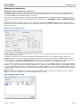
1
PowerMatch™ PM8500 Configurable Professional Amplifier PowerMatch™ PM8500N Configurable Professional Amplifier PM8500 / PM8500N PowerMatch ™ Configurable Professional Power Amplifier User Guide This Page intentionally blank pro.Bose.comContents Introduction..................................................................................................................................................... 12 Additional Documents................................................................................................................................. 12 Product Features........................................................................................................................................... 12 PowerMatch™ Amplifier Product Line Overview................................................................................ 13 PowerMatch PM8500 and PM8500N...................................................................................................... 13 Accessory Cards..................................................................................................................................... 13 Ideal for use with RoomMatch™ array module loudspeakers................................................................. 13 Interfacing with a ControlSpace® ESP-88 engineered sound processor................................................. 13 Controls, Display, and Connectors.......................................................................................................... 14 Hardware Installation................................................................................................................................... 15 Unpacking............................................................................................................................................... 15 Rack Mounting........................................................................................................................................ 15 Ventilation................................................................................................................................................ 15 AC Mains Outlet Requirements............................................................................................................... 15 Making Connections.................................................................................................................................... 16 Connection and Configuration Steps...................................................................................................... 16 Power (Mains) Connection....................................................................................................................... 16 Standby Mode......................................................................................................................................... 16 Wiring Input Connectors.......................................................................................................................... 17 Fault Notification Output......................................................................................................................... 19 Setup and Configuration............................................................................................................................ 20 Configuration Methods............................................................................................................................ 20 Control Panel Description........................................................................................................................ 21 Front Panel Control Menu Structure........................................................................................................ 22 Control Menu Descriptions...................................................................................................................... 22 Setting the Limiting Function for use with 3rd Party Loudspeakers........................................................ 33 Sample Output Configurations for Different Loudspeaker Loads................................................ 34 Configuration of a RoomMatch™ Four-Module Array (Example 1).......................................................... 34 Configuration of RoomMatch™ Two-Module Array with a RoomMatch RMS215 Subwoofer Module (Example 2).............................................................................................................................................. 35 Maintenance Operations............................................................................................................................ 36 Updating Firmware and Speaker EQ Presets.......................................................................................... 36 Saving and Recalling Amplifier Settings.................................................................................................. 37 About the Alarm Log and Fault Indicator................................................................................................. 38 Troubleshooting............................................................................................................................................. 39 Appendix.......................................................................................................................................................... 40 Function Table......................................................................................................................................... 40 Specifications.......................................................................................................................................... 41 AC Current Draw and Thermal Dissipation Information.......................................................................... 42 English User Guide Page 3 Important Safety Information pro.Bose.com This product is intended for installation by professional installers only! Thank you for selecting Bose® PowerMatch™ amplifiers for your sound reinforcement system. This document is intended to provide professional installers with basic installation and safety guidelines for Bose PowerMatch amplifiers in typical fixed-installation systems. Please read this document before attempting installation. WARNING: Do not expose this apparatus to dripping or splashing, and do not place objects filled with liquids such as vases, on or near the apparatus. As with any electronic products, use care not to spill liquids into any part of the system. Liquids can cause a failure and/or a fire hazard. The lightning flash with arrowhead symbol, within an equilateral triangle, is intended to alert the user to the presence of uninsulated dangerous voltage within the system enclosure that may be of sufficient magnitude to constitute a risk of electrical shock. Do not touch the output terminals while amplifier power is ON. Make all connections with amplifier OFF. The exclamation point within an equilateral triangle, as marked on the system, is intended to alert the user to the presence of important operating and maintenance instructions in this installation guide. CAUTION: Make no modifications to the amplifier or accessories. Unauthorized alternations may compromise safety, regulatory compliance, and system performance. CAUTION: This product shall be connected to an AC mains socket outlet with a protective earthing (grounding) connection. CAUTION: Where the AC mains plug is used as the disconnect device, such disconnect device shall remain fully operable. Important Safety Instructions 1. Read these instructions. 2. Keep these instructions – for future reference. 3. Heed all warnings – on the product and in all product documentation. 4. Follow all instructions. 5. Do not use this apparatus near water or moisture. 6. Clean only with a dry cloth. 7. Do not block any ventilation openings. Install in accordance with the manufacturer’s instructions. To ensure reliable operation of the product and to protect it from overheating, put the product in a position and location that will not interfere with its proper ventilation. 8. Do not install near any heat sources, such as radiators, heat registers, stoves, or other apparatus (including amplifiers) that p roduce heat. 9. Do not defeat the safety purpose of the polarized or grounding-type plug. A polarized plug has two blades with one wider than the other. A grounding-type plug has two blades and a third grounding prong. The wider blade or third prong is provided for your safety. If the provided plug does not fit in your outlet, consult an electrician for replacement of the obsolete outlet. 10. Protect the power cord from being walked on or pinched, particularly at plugs, convenience receptacles, and the point where they exit from the apparatus. 11. Only use attachments/accessories specified by the manufacturer. 12. Use only with the cart, stand, tripod, bracket, or table specified by the manufacturer or sold with the apparatus. When a cart is used, use caution when moving the cart/apparatus combination to avoid injury from tip-over. 13. Unplug this apparatus during lightning storms or when unused for long periods of time to prevent damage to this product. 14. Refer all servicing to qualified service personnel. Servicing is required when the apparatus has been damaged in any way such as power-supply cord or plug is damaged; liquid has been spilled or objects have fallen into the apparatus; the apparatus has been exposed to rain or moisture, does not operate normally, or has been dropped. Do not attempt to service this product yourself. Opening or removing covers may expose you to dangerous voltages or other hazards. Please call Bose to be referred to an authorized service center near you. Page 4 Installation and Safety Guidelines English pro.Bose.comImportant Safety Information 15. To prevent risk of fire or electric shock, avoid overloading wall outlets, extension cords, or integral convenience receptacles. 16. Do not let objects or liquids enter the product – as they may touch dangerous voltage points or short-out parts that could result in a fire or electric shock. 17. See product enclosure for safety-related markings. 18. No naked flame sources, such as lighted candles, should be placed on the apparatus. 19. The mains plug is used to disconnect the device and it shall remain readily operable. To completely disconnect the power input, the mains plug of the apparatus shall be disconnected from the mains. 20. The front-panel LCD screen will illuminate when the product has mains power. If power is applied and the LCD screen is not illuminated, please send the unit for service. 21. Do not allow the unit to exceed the maximum operating ambient temperature of 40° C. Be aware of conditions in an enclosed rack that may increase the temperature above room ambient conditions. Note: The product must be used indoors. It is neither designed nor tested for use outdoors, in recreational vehicles, or on boats. This product conforms with all EU Directive requirements as applicable by law. The complete Declaration of Conformity can be found at www.Bose.com/static/compliance. This Product meets the immunity requirements for the E2 class EN55103-2 directive. Initial turn on inrush current: 14.8 Amps (230V / 50 Hz) Inrush current after 5 seconds AC mains interruption: 15.4 Amps (230V / 50 Hz) Information About Products That Generate Electrical Noise (FCC Compliance Notice for U.S.) Note: This equipment has been tested and found to comply with the limits for a Class A digital device, pursuant to part 15 of the FCC Rules. These limits are designed to provide reasonable protection against harmful interference when the equipment is operated in a commercial environment. This equipment generates, uses, and can radiate radio frequency energy and, if not installed and used in accordance with the instruction manual, may cause harmful interference to radio communications. Operation of this equipment in a residential area is likely to cause harmful interference in which case the user will be required to correct the interference at one’s own expense. This product complies with the Canadian ICES-003 Class A specifications. English Installation and Safety Guidelines Page 5 Información de seguridad importante pro.Bose.com Sólo un instalador profesional deberá montar este producto. Gracias por seleccionar los amplificadores Bose® PowerMatch™ para su sistema de refuerzo de sonido. Este documento ofrece a los instaladores profesionales instrucciones básicas de instalación y seguridad para los amplificadores Bose PowerMatch™ en sistemas típicos de instalación fija. Lea este documento antes de intentar la instalación. ADVERTENCIA: No exponga este aparato a salpicaduras o goteo. No coloque encima o cerca del aparato objetos que contengan líquidos, como jarrones. Al igual que con cualquier producto electrónico, evite que se derramen líquidos en los componentes del sistema, ya que pueden provocar averías o riesgo de incendio. El símbolo de relámpago con una flecha dentro de un triángulo equilátero indica al usuario que la caja del sistema puede contener una tensión sin aislar de magnitud suficiente para constituir un riesgo de descarga eléctrica. No toque los terminales de salida mientras el amplificador está encendido. Realice todas las conexiones con el amplificador apagado. El signo de exclamación dentro de un triángulo equilátero, tal como aparece marcado en el sistema, avisa al usuario de que existen instrucciones de operación y mantenimiento importantes en esta guía de instalación. PRECAUCIÓN: No realice modificaciones en el amplificador o los accesorios. Las alteraciones no autorizadas pueden comprometer aspectos de seguridad, cumplimiento normativo y rendimiento del sistema. PRECAUCIÓN: Este producto se debe conectar a una toma de la red eléctrica con una conexión de tierra que sirva de protección. PRECAUCIÓN: Si se utiliza la clavija de red como dispositivo de desconexión, deberá poder accionarse fácilmente. Instrucciones de seguridad importantes 1. Lea las siguientes instrucciones. 2. Guarde estas instrucciones para consultarlas en el futuro. 3. Respete todas las advertencias que se indican en el producto y en la documentación. 4. Siga todas las instrucciones. 5. No utilice este aparato cerca del agua o humedad. 6. Límpielo sólo con una bayeta seca. 7. No bloquee las aberturas de ventilación. Instálelo siguiendo las instrucciones del fabricante. Para garantizar un funcionamiento fiable del producto y evitar que se recaliente, colóquelo en una ubicación y posición que permitan una ventilación adecuada. 8. No lo instale cerca de fuentes de calor, tales como radiadores, salidas de aire caliente, cocinas u otros aparatos (incluidos amplificadores) que generen calor. 9. No elimine el mecanismo de seguridad del enchufe con toma a tierra o polarizado. Los enchufes polarizados disponen de dos clavijas, una de mayor tamaño que la otra. Los enchufes con toma a tierra tienen dos clavijas y un tercer terminal de tierra. La patilla más ancha y el tercer terminal se incluyen como medida de seguridad. Si el enchufe suministrado no encaja en la toma, póngase en contacto con un electricista para sustituir la toma antigua. 10. Proteja el cable de alimentación de forma que nadie lo pise ni quede pinzado, en particular cerca de enchufes, receptáculos de tomas múltiples y en el lugar en que sale del aparato. 11. Utilice sólo conexiones y accesorios suministrados por el fabricante. 12. Utilícelo sólo con el carrito, soporte, trípode, abrazadera o mesa suministrados por el fabricante o incluidos con el dispositivo. Cuando utilice un carrito, tenga cuidado al mover el carrito con el dispositivo para evitar que caiga y produzca daños. 13. Desenchufe el dispositivo si se produce una tormenta eléctrica o si no lo va a utilizar durante periodos prolongados de tiempo para evitar que se dañe. 14. Toda reparación debe ser realizada por personal cualificado. Lleve el dispositivo a reparar si presenta algún daño como, por ejemplo, si el cable de alimentación o el enchufe están dañados, si se han vertido líquidos o se han caído objetos sobre el dispositivo o si éste ha estado expuesto a la lluvia o humedad; si no funciona correctamente o se ha caído al suelo. No intente reparar el producto usted mismo. La apertura o retirada de las tapas le expondrá a tensiones peligrosas o a otros peligros. Póngase en contacto con Bose para conocer cuál es el centro de servicio técnico autorizado de su zona. Página 6 Instrucciones de instalación y de seguridad Español pro.Bose.com Información de seguridad importante 15. Para prevenir el riesgo de incendio o descargas eléctricas, evite sobrecargar los enchufes, alargadores o receptáculos de las tomas. 16. Evite que caigan objetos o líquidos sobre el producto, ya que podrían entrar en contacto con puntos de niveles de voltaje altos o partes que podrían sufrir un cortocircuito y causar incendios o descargas eléctricas. 17. Consulte las indicaciones de seguridad en la caja del producto. 18. No coloque sobre el aparato ninguna fuente de llama viva, como velas encendidas. 19. El enchufe de red sirve para desconectar el dispositivo y deberá poder accionarse fácilmente. Para desconectar completamente el aparato, deberá desenchufarse el enchufe de red del aparato. 20. La pantalla LCD del panel frontal se ilumina cuando el producto está conectado a la red. Si se conecta el aparato y no se ilumina la pantalla LCD, envíelo a reparar. 21. No exponga la unidad a temperaturas superiores a 40° C, su temperatura máxima de funcionamiento. Tenga en cuenta todas las situaciones que pueden darse en un bastidor cerrado y que podrían aumentar la temperatura por encima de las condiciones ambientales de la sala. Nota: Este producto debe utilizarse en interiores. No está diseñado ni ha sido probado para uso al aire libre o en embarcaciones. Este producto cumple los requisitos de todas las Directivas de la UE aplicables legalmente. Encontrará la declaración de conformidad completa en www.Bose.com/static/compliance. Este producto cumple los requisitos de inmunidad que establece la Directiva EN55103-2 para la clase E2. Corriente de irrupción en encendido inicial: 14,8 Amps (230 V / 50 Hz) Corriente de irrupción después de 5 segundos de interrupción de la corriente de red: 15,4 Amps (230 V / 50 Hz) Información sobre productos que generan ruido eléctrico (Nota de homologación FCC para EE UU) Nota: Este equipo se ha probado y ha demostrado que cumple con los límites para dispositivos digitales de clase B, de acuerdo con el apartado 15 de las normas de la FCC. Estos límites están diseñados para ofrecer una protección razonable contra las interferencias perjudiciales cuando el aparato se utiliza en un entorno comercial. Este equipo genera, utiliza y puede irradiar energía de radiofrecuencia y, si no se instala y se utiliza de acuerdo con el manual de instrucciones, podría ocasionar interferencias perjudiciales para las comunicaciones por radio. La utilización de este equipo en una zona residencial podría causar interferencias dañinas. En ese caso, la corrección de la interferencia correrá a cargo del usuario. Este producto cumple las especificaciones canadienses para dispositivos de clase A ICES-003. Español Instrucciones de instalación y de seguridad Página 7 Informations importantes pour la sécurité pro.Bose.com L’installation de ce produit est réservée à un technicien professionnel ! Merci d’avoir choisi des amplificateurs professionnels Bose® PowerMatch™ pour votre système d’amplification du son. Ce document à l’intention des installateurs professionnels contient les directives de pose et de sécurité relatives aux amplificateurs professionnels Bose PowerMatch™ en installation fixe. Lisez attentivement ce document avant l’installation. AVERTISSEMENT : Protégez l’appareil de tout risque de ruissellement ou d’éclaboussure. Ne placez pas d’objets contenant des liquides, tels que des vases, sur l’appareil. Comme avec tout appareil électronique, veillez à ne pas renverser de liquides sur une partie quelconque de l’appareil. Les liquides peuvent provoquer des pannes et/ou un risque d’incendie. Le symbole représentant un éclair avec une flèche à l’intérieur d’un triangle équilatéral est utilisé pour prévenir l’utilisateur de la présence d’une tension électrique dangereuse non isolée à l’intérieur de l’appareil. Cette tension est d’un niveau suffisamment élevé pour représenter un risque d’électrocution. Ne touchez pas les bornes de sortie lorsque l’amplificateur est allumé. Mettez l’amplificateur hors tension avant de réaliser toute connexion. Le symbole représentant un point d’exclamation à l’intérieur d’un triangle équilatéral, tel qu’il figure sur le système, signale à l’utilisateur la présence d’instructions importantes relatives au fonctionnement et à l’entretien de l’appareil dans cette notice d’installation. ATTENTION : N’apportez aucune modification à l’amplificateur ou aux accessoires. Toute modification non autorisée peut compromettre votre sécurité, le respect des réglementations et les performances. ATTENTION : Cet appareil doit être raccordé à une prise secteur dotée d’une mise à la terre. ATTENTION : Si la fiche d’alimentation est utilisée comme dispositif de débranchement de l’appareil, elle doit rester facilement accessible. Instructions importantes relatives à la sécurité 1. Veuillez lire ces instructions. 2. Conservez-les pour toute référence ultérieure. 3. Respectez tous les avertissements qui figurent sur le produit ou dans sa notice d’utilisation. 4. Suivez toutes les instructions. 5. N’utilisez pas cet appareil à proximité d’eau ou d’une source d’humidité. 6. Utilisez uniquement un chiffon sec pour le nettoyage. 7. Ne bloquez jamais les orifices d’aération. Suivez les instructions du fabricant pour l’installation. Pour garantir un fonctionnement fiable du produit et le protéger contre tout risque de surchauffe, installez-le à un emplacement et dans une position permettant d’assurer une ventilation correcte. 8. N’installez pas cet appareil à proximité d’une quelconque source de chaleur, telle qu’un radiateur, une arrivée d’air chaud, un four ou tout autre appareil (notamment des amplificateurs) produisant de la chaleur. 9. Veillez à profiter de la sécurité offerte par les fiches de type terre ou polarisées. Les fiches polarisées sont équipées de deux bornes de largeurs différentes. Les fiches de type terre sont équipées de deux bornes et d’un orifice pour la mise à la terre. Ces deux types de dispositifs ont pour but d’assurer votre sécurité Si la prise fournie ne s’adapte pas à votre prise de courant, consultez un électricien pour qu’il remplace cette prise obsolète. 10. Protégez le cordon d’alimentation contre les risques de piétinement ou de pincement, notamment au niveau des fiches, des prises de courant et des branchements à l’appareil. 11. Utilisez uniquement les accessoires spécifiés par le fabricant. 12. Utilisez uniquement le chariot, le support, le trépied, l’équerre ou la table spécifié(e) par le fabricant ou vendu(e) avec l’appareil. Si vous utilisez un chariot, faites attention à ne pas faire basculer l’ensemble chariot/appareil. 13. Débranchez cet appareil pendant les orages ou au cours des longues périodes de non utilisation afin d’éviter de l’endommager. 14. Confiez toute réparation à du personnel qualifié. Une réparation est nécessaire lorsque l’appareil a été endommagé de quelque façon que ce soit (endommagement du cordon d’alimentation ou de la fiche électrique, renversement d’un liquide ou de tout objet sur l’appareil, exposition de l’appareil à la pluie ou à l’humidité, mauvais fonctionnement, chute de l’appareil, etc.). Ne tentez pas de réparer ce produit vous-même. L’ouverture ou la dépose d’un couvercle risque de vous exposer à des tensions électriques ou autres dangers. Veuillez contacter Bose pour connaître les coordonnées du centre de réparation agréé le plus proche. Page 8 Installation et instructions de sécurité Français pro.Bose.com Informations importantes pour la sécurité 15. Pour éviter tout risque d’incendie ou d’électrocution, ne surchargez pas les prises murales, les rallonges ou les prises multiples. 16. Ne laissez jamais de l’eau ou des objets pénétrer à l’intérieur du produit : des éléments sous tension pourraient être touchés, et un court-circuit risquerait de provoquer un incendie ou une électrocution. 17. Consultez les marquages de sécurité sous le boîtier du produit. 18. Ne placez jamais d’objets enflammés, tels que des bougies allumées, sur l’appareil. 19. La fiche d’alimentation est utilisée comme dispositif de débranchement de l’appareil et doit rester facilement accessible. Pour déconnecter totalement l’appareil du secteur, débranchez-le de la prise électrique. 20. L’écran du panneau d’affichage LCD est illuminé lorsque le produit est alimenté. Si le produit est alimenté et que l’écran LCD n’est pas allumé, veuillez faire réviser l’appareil. 21. Veillez à ne pas utiliser l’appareil à une température supérieure à 40° C. Gardez à l’esprit le fait que la température à l’intérieur d’un rack fermé peut être très supérieure à la température ambiante. Remarque : Ce produit doit être utilisé en intérieur. Il n’a pas été conçu ni testé pour une utilisation en extérieur, dans des véhicules ou sur des bateaux. Ce produit est conforme à toutes les directives de la Communauté Européenne qui s’y appliquent. L’attestation complète de conformité est disponible à l’adresse www.bose.com/static/compliance. Ce produit répond aux critères d’immunité des directives EN55103-2 pour les appareils de classe E2. Courant d’appel à la mise sous tension : 14,8 A (230V / 50 Hz) Courant d’appel après une interruption de 5 secondes de l’alimentation secteur : 15,4 A (230V / 50 Hz) Informations sur les produits générateurs de bruit électrique (Notice de conformité FCC pour les USA) Remarque : Ce matériel a fait l’objet de tests prouvant sa conformité aux limites imposées aux appareils numériques de classe A, conformément à la partie 15 des réglementations de la FCC. Ces limites sont conçues pour offrir une protection raisonnable contre les interférences nuisibles lorsque l’appareil est utilisé en environnement commercial. Cet appareil génère, utilise et est susceptible d’émettre de l’énergie à des fréquences radio. À ce titre, s’il n’est pas installé ou utilisé conformément aux instructions, il est susceptible de perturber les communications radio. L’utilisation de cet équipement dans une zone résidentielle risque de provoquer des interférences nuisibles, auquel cas l’utilisateur devra remédier au problème à ses propres frais. Ce produit est conforme aux spécifications de la réglementation ICES-003 pour la classe A du Canada. Français Installation et instructions de sécurité Page 9 Wichtige Sicherheitshinweise pro.Bose.com Dieses Produkt darf nur von fachkundigen Monteuren installiert werden! Vielen Dank, dass Sie Bose® PowerMatch™Verstärker für Ihr Klangverstärkungssystem gewählt haben. Dieses Dokument soll fachkundigen Monteuren grundlegende Installations- und Sicherheitsrichtlinie für Bose PowerMatch™-Verstärker in typischen Festinstallationssystemen bieten. Bitte lesen Sie dieses Dokument vor der Installation durch. WARNUNG: Schützen Sie das Gerät vor tropfenden oder spritzenden Flüssigkeiten, und stellen Sie keine mit Flüssigkeiten gefüllten Gefäße (z. B. Vasen) auf das Gerät oder in die Nähe des Geräts. Wie bei allen elektronischen Geräten dürfen niemals Flüssigkeiten ins Innere gelangen. Dadurch kann es zu Fehlfunktionen oder Bränden kommen.. Das Blitzsymbol mit Pfeilspitze in einem gleichseitigen Dreieck weist den Benutzer auf das Vorhandensein einer nicht isolierten gefährlichen elektrischen Spannung innerhalb des Systemgehäuses hin, durch die die Gefahr von Stromschlägen besteht. Berühren Sie die Ausgangsanschlüsse nicht, wenn der Verstärker eingeschaltet ist. Schalten Sie alle Anschlüsse am Verstärker aus. Das Ausrufezeichen in einem gleichseitigen Dreieck, wie es am System angebracht ist, soll den Benutzer auf wichtige Bedienungs- und Wartungsanweisungen in dieser Installationsanleitung aufmerksam machen. ACHTUNG: Nehmen Sie keine Veränderungen am Verstärker oder am Zubehör vor. Nicht autorisierte Veränderungen können die Sicherheit, die Erfüllung von Richtlinien und die Systemleistung beeinträchtigen. ACHTUNG: Dieses Produkt muss an eine Steckdose mit Erdungsschutz angeschlossen werden. ACHTUNG: Falls Sie den Netzstecker verwenden, um das Gerät von der Stromversorgung zu trennen, sollten Sie sicherstellen, dass Sie jederzeit auf den Stecker zugreifen können. Wichtige Sicherheitshinweise 1. Lesen Sie die folgenden Anweisungen. 2. Bewahren Sie diese Anweisungen auf – zum späteren Nachschlagen. 3. Beachten Sie alle Warnhinweise – am Produkt und in der gesamten Produktdokumentation. 4. Befolgen Sie alle Anweisungen. 5. Verwenden Sie dieses Gerät nicht in der Nähe von Wasser oder Feuchtigkeit. 6. Reinigen Sie das Gerät nur mit einem sauberen, trockenen Tuch. 7. Achten Sie darauf, dass die Lüftungsöffnungen nicht blockiert sind. Stellen Sie das Gerät nur in Übereinstimmung mit den Herstelleranweisungen auf – Stellen Sie es nur an einem Ort auf, an dem eine gute Ventilation gewährleistet ist, um den zuverlässigen Betrieb des Geräts sicherzustellen und es gegen Überhitzung zu schützen. 8. Stellen Sie das Gerät nicht in der Nähe von Wärmequellen auf, wie Heizkörper, Wärmespeicher, Öfen oder andere Geräten (auch Verstärker), die Wärme erzeugen. 9. Beeinträchtigen Sie in keiner Weise die Schutzfunktion des Schutzkontaktsteckers. Ein gepolter Stecker hat zwei Stromkontakte, von denen einer breiter als der andere ist. Ein Schutzkontaktstecker hat zwei Stromkontakte und einen dritten Erdungskontakt. Der dritte Kontakt dient der Sicherheit. Falls der mitgelieferte Stecker nicht in Ihre Steckdose passt, wenden Sie sich an einen qualifizierten Elektriker, um die Steckdose auszutauschen. 10. Verlegen Sie das Netzkabel so, dass es keine Stolpergefahr darstellt und nicht beschädigt werden kann – insbesondere im Bereich von Steckern und Steckdosen und dort, wo das Netzkabel aus dem Gerät herausgeführt wird. 11. Verwenden Sie nur Zubehör-/Anbauteile, die vom Hersteller zugelassen sind. 12. Verwenden Sie für das Gerät nur Rollwagen, Ständer, Dreibeine, Halterungen oder Tische, die vom Hersteller zugelassen sind oder zusammen mit dem Gerät verkauft werden. Falls Sie einen Rollwagen verwenden, dürfen Sie die Einheit Gerät/Rollwagen nur mit Vorsicht bewegen, damit Verletzungen beim möglichen Umkippen ausgeschlossen sind. 13. Ziehen Sie den Netzstecker des Geräts während eines Gewitters oder wenn Sie das Gerät längere Zeit nicht benutzen – zur Vermeidung von Schäden am Produkt. Seite 10 Installations- und Sicherheitshinweise Deutsch pro.Bose.com Wichtige Sicherheitshinweise 14. Wenden Sie sich bei allen Reparatur- und Wartungsarbeiten nur an qualifiziertes Kundendienstpersonal. Wartungsarbeiten sind in folgenden Fällen nötig: Bei jeglichen Beschädigungen wie z. B. des Netzkabels oder des Netzsteckers, wenn Flüssigkeiten oder Gegenstände in das Gehäuse gelangt sind, das Gerät Regen oder Feuchtigkeit ausgesetzt wurde, fallen gelassen wurde oder nicht ordnungsgemäß funktioniert – Versuchen Sie in solchen Fällen keinesfalls, das Gerät selbst zu reparieren. Öffnen oder entfernen Sie unter keinen Umständen die Gehäuseabdeckungen, da Sie andernfalls mit gefährlichenelektrischen Spannungen in Berührung kommen oder anderen Gefahren ausgesetzt sein könnten. Wenden Sie sich telefonisch an Bose, um die Anschrift eines autorisierten Kundendienstzentrums in Ihrer Nähe zu erfragen. 15. Vermeiden Sie Gefahren durch Brände oder elektrische Schläge, indem Sie Steckdosen, Verlängerungskabel und integrierte Gerätesteckdosen nicht überlasten. 16. Lassen Sie keine Flüssigkeiten oder Fremdkörper in das Gerät gelangen – sie können unter gefährliche elektrische Spannung gesetzt werden oder Bauteile kurzschließen und folglich Brände und Stromschläge auslösen. 17. Beachten Sie die Sicherheitshinweise auf der Geräterückseite. 18. Stellen Sie keine brennenden Kerzen und kein offenes Licht auf das Gerät. 19. Der Netzstecker wird zum Trennen des Geräts verwendet und Sie sollten sicherstellen, dass Sie jederzeit auf den Stecker zugreifen können. Um die Stromzufuhr komplett zu trennen, muss der Netzstecker des Geräts aus der Netzsteckdose gezogen werden. 20. Die Vorderseite des LCD-Bildschirms leuchtet, wenn das Produkt Strom erhält. Wenn Strom anliegt und der LCD-Bildschirm nicht leuchtet, geben Sie das Gerät bitte zur Reparatur. 21. Achten Sie darauf, dass die Betriebstemperatur des Geräts 40 °C nicht überschreitet. Seien Sie sich aller Bedingungen in einem geschlossenen Rack bewusst, welche zu einem Anstieg der Temperatur über Zimmerniveau führen können. Hinweis: Das Produkt ist nicht für den Einsatz im Freien geeignet. Verwenden Sie es nur innerhalb von Gebäuden und nicht in Campingfahrzeugen, auf Booten o. ä. Dieses Produkt erfüllt alle vorgeschriebenen EU-Richtlinien. Die vollständige Konformitätserklärung ist einsehbar unter www. bose.com/static/compliance. Dieses Produkt erfüllt die Anforderungen an die Störfestigkeit der Klasse E2 der Richtlinie EN55103-2. Anfänglicher Einschaltstrom: 14,8 A (230 V/50 Hz) Einschaltstrom nach 5 Sekunden Unterbrechung des Netzanschlusses: 15,4 A (230 V/50 Hz) Informationen über Produkte, die elektrisches Rauschen verursachen (Hinweis zur FCC-Einhaltung für die USA) Hinweis: Dieses Gerät wurde geprüft. Es stimmt mit den Regelungen für Geräte der Klasse A gemäß Teil 15 der FCC-Vorschriften überein. Diese Grenzwerte sollen einen angemessenen Schutz gegen elektromagnetische Störungen beim Betrieb in gewerblicher Umgebung gewährleisten. Dieses Gerät erzeugt und verwendet Hochfrequenzstrahlung und kann sie auch aussenden. Daher verursacht das Gerät, wenn die Installation und Benutzung nicht in Übereinstimmung mit dieser Bedienungsanleitung erfolgt, möglicherweise Störungen des Funkverkehrs. Beim Betrieb dieses Geräts in Wohngebieten können erhebliche Störungen des Funkverkehrs verursacht werden. Eventuell daraus entstehende Kosten trägt allein der Benutzer des Geräts. Dieses Produkt erfüllt die kanadische Richtlinie ICES-003, Klasse A. Deutsch Installations- und Sicherheitshinweise Seite 11 User Guide pro.Bose.com Introduction Thank you for choosing the Bose® PowerMatch™ PM8500 configurable professional power amplifier! The PowerMatch PM8500 Configurable Professional Amplifier delivers concert sound quality for fixed-installation sound reinforcement systems. Building on the ruggedness proven by 20 years of experience building Class-D amplifiers for the automotive market, the PowerMatch PM8500 amplifier adds numerous new Bose proprietary technologies to simultaneously provide class-leading power, efficiency, sound quality, and reliability. This document delivers detailed installation and stand-alone configuration information. The information furnished in this guide is intended to help you install and set up the product, but does not include all details of design, production, or variations of the equipment. Nor does it cover every possible situation that may arise during installation, operation, or maintenance. If you need assistance beyond the scope of this guide, please contact your local Bose Representative or Technical Support specialist. Throughout this document, the naming convention “PM8500” refers to both the PM8500 and PM8500N versions, unless stated otherwise. Additional Documents The following additional documents can help guide you through the setup and use of this product: • PowerMatch PM8500 Configurable Professional Amplifier Installation and Safety Guidelines This document outlines safety warnings, precautions, basic setup, and configuration. A printed version of this guide is supplied with the amplifier. • ControlSpace Designer™ Software User Guide (PDF) This document provides detailed instructions on how to use ControlSpace Designer PC software to fully configure, update, network control, and monitor the PowerMatch amplifier. This document and the free C ontrolSpace Designer software can be downloaded from pro.Bose.com. Product Features • PowerMatch Class-D Amplifier New, proprietary design combines Class-D efficiency with a dual feedback circuit that continuously monitors and controls both the current and voltage of the output devices. This combination provides the PowerMatch amplifier with the highest-quality output power, audio performance, reliability, and efficiency. • QuadBridge™ Output Mode Outputs can be configured as single, dual, or quad channel modes, which allows 4 kW of power to be allocated between 2 to 8 channels. These software-selectable configurations range from 8 channels at 500 watts, 4 channels at 1000 watts, 2 channels at 2000 watts, or mixed combinations. Dual or quad modes can drive either low-impedance or 70 V or 100 V loads. • PeakBank™ Power Supply Regenerative 4-quadrant power supply with fast-tracking Power Factor Correction (PFC) supports high efficiency, while improving the peak burst power for superior transient response and current reserve for bass impact. • 8 x 500 W from Single AC Mains Outlet The PM8500 delivers 4 kW rated power from a single AC mains outlet, with greater than 75% conversion efficiency. • Optimized Loudspeaker Processing Integrated audio DSP for loudspeaker EQ, crossover, delay, and limiting. When used with RoomMatch™ and other Bose loudspeakers, the presets provide all required signal processing with optimized protection limiting of self-powered loudspeakers. • Software Setup and Network Monitoring All models have USB for Bose ControlSpace Designer software programming, with PM8500N adding Ethernet network control and monitoring. Page 12 User Guide English User Guide pro.Bose.com PowerMatch™ Amplifier Product Line Overview PowerMatch PM8500 and PM8500N The PowerMatch PM8500 and PM8500N are configurable professional audio amplifiers. The two versions are identical except that the PM8500N version adds an RJ45 connector on the rear panel to allow network setup, control, and remote monitoring of multiple PM8500N units using Bose® ControlSpace® Designer™ software and standard network equipment. Accessory Cards The PM8500 features a digital input slot that allows for accessory plug-in cards to be used. These cards allow for added I/O flexibility. For example, the PM ESPLink card provides a shared 8-channel uncompressed digital audio bus between one or more PM8500 units and a ControlSpace ESP engineered sound processor. Visit pro.Bose.com for information on other available accessory cards. Ideal for use with RoomMatch™ array module loudspeakers RoomMatch loudspeakers connect and configure easily to PM8500 amplifiers. Built-in loudspeaker and array EQs together with suitable output power ratings make the PM8500 amplifier an ideal counterpart in designs using RoomMatch array module loudspeakers. Interfacing with a ControlSpace® ESP-88 engineered sound processor PowerMatch amplifiers are designed to integrate with existing ControlSpace products, including the ESP-88 processor. While PowerMatch amplifiers can operate without an ESP-88 processor, the ESP-88 processor enables comprehensive signal routing, processing, control, and distribution capability. When the ControlSpace ESP-88 processor is used with an installed ESPLink output card, the ESP-88 becomes the input signal entry and processing point. Multiple PM8500 amplifiers equipped with PM ESPLink cards can receive and pass-through 8 channels of uncompressed digital audio. Figure 1 below shows an example of one ESP-88 processor sharing 8 channels of audio to three PM8500 amplifiers. Visit pro.Bose.com for details on the full ControlSpace line of products and accessories. Figure 1. Bose® ESPLink connection example TOSLINK™ cable PM8500 amplifier with PM ESPLink card ESP-88 processor with ESPLink 8-ch output card PM8500 amplifier with PM ESPLink card TOSLINK™ cable TOSLINK™ cable PM8500 amplifier with PM ESPLink card English User Guide Page 13 User Guide pro.Bose.com Controls, Display, and Connectors Figures 2 and 3 detail the various elements found on the front and rear panels of the PM8500 and PM8500N amplifiers. Figure 2. PM8500 and PM8500N Front Panel View 2 1 6 8 3 5 7 8 4 1. LED Indicators 5. Menu Soft Keys (1-5) 2. LCD 6. USB connector 3. Navigation Soft Key 7. Front airflow vents 4. Rotary Encoder 8. Front rack-mount ears Figure 3. PM8500N Rear Panel View (PM8500 identical except no RJ-45 network connector) 12 18 9 11 14 10 13 16 9. Analog Input connectors (A-H) 14. Output connectors (1-4 and 5-8) 10. Fault-Notification Output 15. AC Mains receptacle 11. Ethernet RJ-45 network connector (PM8500N only) 16. AC Mains retention clip 12. Rear airflow vents 17. Power Switch/Resettable Circuit Breaker 13. Digital input card slot cover 18. Rear rack-mount support tabs Page 14 User Guide 18 15 17 English User Guide pro.Bose.com Hardware Installation Unpacking The product box includes the following items: Figure 4. Contents PowerMatch™ PM8500 or PM8500N amplifier Installation and Safety Guidelines IEC C19-type detachable power cord Connector Accessory Pack (P/N 343511-0010) including: 8 Input connectors 2 Output connectors 4 Shorting jumpers 1 Fault Notification Output connector 9 Plastic wire tie-wraps Rack Mounting The PM8500 is designed to fit standard 19-inch (48 cm) rack equipment, occupying 2 rack-units (RU) in height. Use four fasteners with washers (not supplied) to mount the amplifier front panel rack ears to the equipment rack rails. Rack-mount tabs are also provided on the rear of the chassis to secure the amplifier. Ventilation The PM8500 is designed to operate under wide conditions, with continuous operation at 40° C ambient temperature. However, to ensure safe operation, the front panel, side and rear airflow vents should never be blocked. Air flows into the front of the unit and exits the rear and side vents. The internal fans automatically increase speed when the amplifier is producing higher output power. Should the unit exceed safe operating temperature, a gradual reduction of gain will automatically be applied for thermal protection. If the automatic gain reduction does not reduce operating temperatures to safe conditions, the unit will mute all outputs and the red FAULT LED will illuminate on the front panel. AC Mains Outlet Requirements The PM8500 features an efficient, universal switch-mode power supply with Power Factor Correction and can operate with AC Mains line voltages from 100 to 240 volts at 50/60 Hz. With typical music program material, the PM8500 provides full rated power from a single 20-amp, 120V (common in USA) AC mains outlet, or single 16-amp, 230V (common in Europe) mains outlet. High-power amplifiers draw large amounts of current from the AC mains. Use of extension cords to power the amplifier could introduce significant impedance and a resulting voltage drop on the mains that may interfere with normal operation of the amplifier. In countries like Japan where 100V AC mains are used, the following guidelines will be helpful to ensure optimal performance from the PM8500: • Ensure a minimum of 100V AC at the amplifier plug when the amplifier is idle. • Use a dedicated mains circuit for each amplifier. • Locate the amplifiers as close as possible to the mains outlet. • If used, extension cords should be 14 AWG (2 mm2 diameter) or larger. • Extension cords should be less than 2 meters (6.6 ft) in length. English User Guide Page 15 User Guide pro.Bose.com Making Connections Connection and Configuration Steps Use the following procedure when setting up the PM8500 for the first time. Subsequent sections in this guide give details on each step. 1. Install any accessory cards (optional) 2. Mount the amplifier into the rack 3. Connect power cable and retaining clip 4. Turn on amplifier 5. Enable Standby Mode 6. Configure amplifier (use front panel or ControlSpace® Designer™ software) 7. Wire input connection from source device(s) 8. Wire output connectors to speakers 9. Disable Standby Mode 10. Connect Fault Notification Output to management system or device (optional) 11. Reset alarms 12. Test system Power (Mains) Connection Power connection is made using the included IEC power cord. The PM8500 also includes a retaining clip to help secure the power connection to the amplifier. To install, place the retaining clip toward the center of the amplifier, plug in the IEC power cord, then swing the retaining clip so it locks behind the IEC connector. Figure 5. IEC Connector retaining clip in place. Standby Mode Standby mode allows for changing speaker output cabling and software configurations without disconnecting power or triggering alarms in the amplifier. You can enable or disable standby mode from the front panel of the PM8500 using the following steps: MENU -> UTILITY -> STANDBY MODE -> ENTER STANDBY Page 16 User Guide English User Guide pro.Bose.com Wiring Input Connectors The balanced line-level analog inputs utilize 3-pin terminal block connectors (Phoenix Contact #1776168, supplied). For balanced inputs, strip the wire ¼ inch (6 mm) and connect the respective positive, negative, and ground terminals as indicated on the unit and in Figure 6. For unbalanced inputs, the connector should be wired with Pin 1 = positive, with Pin 2 and Pin 3 connected with a jumper wire (not supplied) and then connected to the input cable shield. You can use the supplied tie wraps to help secure the input cables. Figure 6. Balanced and unbalanced connectors (jumper not supplied) Balanced connector Unbalanced connector Wiring Output Connectors The PM8500 features flexible software-selectable output configurations. Power can be allocated between 2 and 8 output channels for specified low-impedance and high-impedance (70V and 100V) loudspeaker loads. The following table describes the behavior of the four available output modes. Mode Description Mono Each channel operates independently, and will drive 2 to 16 Ohm loads V-Bridge Channel pairs are combined to deliver 2x voltage and will drive high impedance (70V or 100V) and 4 to 16 Ohm loads I-Share Channel pairs are combined to deliver 2x current, and will drive 2 Ohm loads Quad Two channel pairs are combined to deliver 2x voltage and 2x current while driving high impedance (70V or 100V) or 4 Ohm loads The loudspeaker outputs utilize two (2) high-current, 8-pin locking terminal block connectors (Phoenix Contact COMBICON® Part #1778120, supplied) that accept cables from 10 to 24 AWG (5.3 - 0.2 mm2 ) in diameter. Note: Use Class 2 wiring for speaker connections. To wire the output connector: 1. Strip the insulation off each speaker terminal to expose 10 mm (3/8") of bare wire. 2. Insert each wire into the correct position on the block connector. Use a small flat-blade (or appropriate) screwdriver to secure the wire. 3. Firmly press the block connector into the receptacle on the amplifier until the left and right latches snap into place. Figure 7. Example of output connector wired for I-Share mode 22+ 1+ 1- To detach the block connector from the amplifier, slide the two orange release tabs toward the amplifier to release the locking tabs. Once released, pull the terminal block connector from the amplifier. Warning: While the amplifier does self-protect under most improper output conditions, misconfiguration of loudspeaker mode and incorrect connection of loudspeakers could damage connected loudspeakers and/or the amplifier. English User Guide Page 17 User Guide pro.Bose.com The following chart shows examples of the types of loads possible and the mode required: Intended Loudspeaker Load Number of Affected Channels Power Rating Max Channels Output Mode 2 to 16 Ohms 1 500 W @ 4Ω 8 Mono 4 to 8 Ohms 2 1000 W @ 8Ω 4 V-Bridge (Low-Z) 70-V “constant voltage” lines 2 800 W @ 70V 4 V-Bridge (70V) 100-V “constant voltage” lines 2 1000 W @ 100V 4 V-Bridge (100V) 2 Ohms requiring high current 2 1000 W @ 2Ω 4 I-Share (Low-Z) 4 Ohms requiring high power 4 2000 W @ 4Ω 2 Quad (Low-Z) 70-V “constant voltage” lines 4 1600 W @ 70V 2 Quad (70V) 100-V “constant voltage” lines 4 2000 W @ 70V 2 Quad (100V) Note: Configure the output mode of the amplifier before connecting loudspeakers. See page 24 for details on front panel configuration. Carefully follow the proper connection method for the selected output configuration. The wiring of the connector varies by amplifier output configuration. The output pin assignments for Mono (single channel) and V-bridge configurations are printed on the rear panel of the amplifier. The following graphics illustrate wiring examples for the different output configuration modes. Figure 8. Output wiring showing the four basic configurations Page 18 User Guide English pro.Bose.com User Guide Figure 9. Output wiring showing mixed configuration Note: Changing the output configuration will automatically place the unit in Standby Mode to allow the safe installation of loudspeaker cable connections to the rear-panel output terminal blocks. Fault Notification Output The PM8500 features a hardware fault notification circuit. This circuit drives a normally open or normally closed contact closure (1A, 30 VDC maximum). The fault output, using the orange-colored 3-pin terminal block (Phoenix Contact #1976010, supplied), is intended to provide an external connection to a remote system monitor for fault notification purposes. Pin assignments are noted in Figure 10. Figure 10. Fault Notification output connector English User Guide Page 19 User Guide pro.Bose.com Setup and Configuration Figure 11 shows the basic signal flow and available DSP functions available to manipulate each individual input channel. Some functions and advanced parameters can only be modified using ControlSpace® Designer™ software. See “Function Table” on page 40 to view configurations required to access functions and features. Figure 11. Simplified DSP block diagram PEQ-5band Analog In PEQ-5band Analog In PEQ-5band PEQ-5band PEQ-5band PEQ-5band PEQ-5band PEQ-5band 3 D 4 E 5 F 6 G 7 H 8 Signal Generator Delay Amp Output SpeakerPEQ Limiter Delay Amp Output Band Pass SpeakerPEQ Limiter Delay Amp Output Band Pass SpeakerPEQ Limiter Delay Amp Output Out 3 Out 4 SpeakerPEQ Limiter Delay Amp Output Out 5 Band Pass SpeakerPEQ Limiter Delay Amp Output Out 6 Band Pass SpeakerPEQ Limiter Delay Amp Output Out 7 Band Pass Array EQ In H Limiter Out 2 Band Pass Array EQ In G Analog In C SpeakerPEQ Out 1 Band Pass Array EQ In F Analog In 2 Array EQ In E Analog In B Array EQ In D Analog In 1 Array EQ In C Analog In Band Pass A Array EQ In B Analog In Matrix Array EQ In A SpeakerPEQ Limiter Delay Amp Output Out 8 Signal Generator Configuration Methods There are three methods to configure the PM8500 amplifier for use. The table below shows those methods and describes functionality differences between the methods. Method of Configuration Advantage Disadvantage Local front panel Fast, easy access to basic loudspeaker processing and control options. Lacking graphical tools, control and DSP functions only available using ControlSpace Designer software such as input and speaker equalization. USB connection to ControlSpace Designer software Full-featured control and visibility over all DSP functions. Graphical tools available to help create EQs for 3rd party loudspeakers, realtime display and monitoring. With RJ45 connection, multiple amplifiers can be configured and monitored from a PC. Requires a PC running the ControlSpace Designer software and a USB connection. RJ45 connection to ControlSpace Designer software (PM8500N only) Page 20 User Guide Requires the PM8500N amplifier, a PC running the ControlSpace Designer software, and a network connection. English User Guide pro.Bose.com Control Panel Description Figure 12. PM8500 Front Panel 5 6 7 8 9 1 2 3 4 10 11 1 Fault LED Indicator LED lights red when a fault condition has been detected. For more information see Figure 21, “Fault Conditions” on page 38. 2 Clip LED Indicator Indicates red when the input signal reaches full scale. Bose recommends that you reduce input levels to prevent this condition. 3 Limit LED Indicator When this LED illuminates, indicates that one or more output channels have reached user-adjustable RMS or Peak threshold values or if system internal protection is occurring. 4 Signal LED Indicator Flashes with the presence of input signal. 5 Hardware Name / Menu Depth Displays the name (either default or assigned) given to this amplifier. This can be changed using ControlSpace® Designer™ software. 6 Meters While at the operating screen (shown), each channel shows the status and level of its output. Muted channels show MUTE in the bar and lumped channel modes show grouped bars as shown above with channels 1-4 and channels 5-6. Output meters automatically change display width to correspond to the active output configuration. 7 IP Address / Device ID Shows the IP address (PM8500N) or device ID number (PM8500). Setting can be modified using ControlSpace Designer software. 8 Navigation Indicator Indicates which menu level will be actuated when the Navigation Soft Key is pressed. 9 Navigation Soft Key Actuates the menu level as indicated by the Navigation Indicator. 10 Menu Soft Keys (1-5) Selects various options that appear on the LCD screen directly above these controls. 11 Rotary Encoder This spin/press control wheel allows scrolling and selection of items shown in lists. English User Guide Page 21 User Guide pro.Bose.com Front Panel Control Menu Structure The displays and user controls accessible by the front panel are presented in the following menu structure illustration: Figure 13. PM8500 menu structure OPERATING Mute All Main Menu MAIN MENU LEVEL METER DSP CONFIG UTILITY LEVEL METER DSP CONFIG UTILITY Output Mute Output Attenuate Input Mute Input Sensitivity Input Source Output Voltage Input Meter Speaker Presets Array EQ Delay Limiting Output Config Input Routing Standby Mode Alarm Log Network Setup (Device ID) Lock Front Panel Set Front Panel Lock Combination Display Restore Factory Settings Firmware Version Control Menu Descriptions The following tables describe each menu item and the various options available to the user from the front panel. OPERATING ➞ OPERATING ➟ Mute All Main Menu Description This is the default operating display for the amplifier. Shows the amplifier name, IP Address/ Device ID and current output configuration. In this case, channels 1-4 are running in Quad mode, channels 5 and 6 are in V-Bridge or I-Share mode, and channels 7 and 8 are running independently in Mono modes. The level shown is -40dB to 0dB full scale. Available Controls Navigation Soft Key: Enters MAIN MENU. Menu Soft Key #5: Mutes/Unmutes ALL output channels. Page 22 User Guide English User Guide pro.Bose.com MAIN MENU OPERATING ➞ Mute All Main Menu Description The MAIN MENU offers five areas of control: • • • • • Available Controls Navigation Soft Key: Back to OPERATING display. • • • • • Notes Level Meter DSP Configuration Utility Menu Soft Key #1: Enters LEVEL menu. Menu Soft Key #2: Enters METER Menu. Menu Soft Key #1: Enters DSP Menu. Menu Soft Key #1: Enters CONFIG Menu. Menu Soft Key #1: Enters UTILITY Menu. Users can set the Power Up State in the ControlSpace® Designer™ software to enable “Restore Last Settings.” If this has been set, a message will display on first entry to the Main Menu. MAIN MENU < LEVEL ➞ LEVEL Output Mute Output Attenuate Input Mute Input Sensitivity Input Source Description The LEVEL menu allows access to the input and output level and type parameters. Available Controls Navigation Soft Key: Back to MAIN MENU. Menu Soft Key #1-5: Changes menu to respective category. Options Output Mute Output Attenuate Input Mute Input Sensitivity Input Source MAIN MENU < OUTPUT MUTE ➞ LEVEL Output Mute Output Attenuate Input Mute Input Sensitivity Input Source Description This display allows each configured output channel to be muted. For channels set to output modes other than Mono, as in the case shown with channels 1-4 above, muting control is bound by the configured groupings. Available Controls To access Output Mute, use the rotary encoder dial from the LEVEL menu to highlight, then press to select. Navigation Soft Key: Back to LEVEL MENU. Rotary Encoder: Scrolls through output channels as displayed under the eight indicator boxes. Menu Soft Key #1-4: Toggles the mute state for each channel listed above each button. Note that some keys may not have channels listed. Menu Soft Key #5: Enables/disables muting of all channels. Options Mute enabled/disabled per channel. Mute ALL enabled/disabled for all channels. Notes Output channels can also be (all) muted from the MAIN MENU and MAIN MENU < METER < OUTPUT VOLTS screens. English User Guide Page 23 User Guide pro.Bose.com MAIN MENU < LEVEL < OUTPUT ATTEN LEVEL ➞ Output Mute Output Attenuate Input Mute Input Sensitivity Input Source Description This display allows you to attenuate each configured output channel. For channels set to output modes other than Mono, attenuation control is bound by the configured groupings. Two output channels are displayed at one time. Real-time output is displayed and affected by changing attenuation. Available Controls To access Output Atten, use the rotary encoder dial from the LEVEL menu to highlight, then press to select. Navigation Soft Key: Back to LEVEL menu. Menu Soft Key #5: Enables channel navigation using the rotary encoder. Menu Soft Key #1 and #3: Enables the respective output channel to be selected. Use the rotary encoder to select attenuation values in dBFS. Options -60dB to 0dB in increments of 0.5dB. MAIN MENU < LEVEL < INPUT MUTE LEVEL ➞ Output Mute Output Attenuate Input Mute Input Sensitivity Input Source Description This display allows you to mute each input channel. Available Controls To access Input Mute, use the rotary encoder dial from the LEVEL menu to highlight, then press to select. Navigation Soft Key: Back to LEVEL menu. Rotary Encoder: Continuously scrolls through two input channel pages, allowing users to access Input A-D and Input E-H. Menu Soft Key #1-4: Toggles the mute state for each channel listed above each button. Menu Soft Key #5: Enables/disables muting of all channels. Options Mute enabled/disabled per channel. Mute ALL enabled/disabled for all channels. Notes All input channels can also be muted from the MAIN MENU < METER < INPUT display. MAIN MENU < LEVEL < INPUT SENS LEVEL ➞ Output Mute Output Attenuate Input Mute Input Sensitivity Input Source Description This display allows you to appropriately match each configured input channel to the incoming signal. This per channel setting corresponds to the level that will create rated power out of the amplifier, with all other gains through the DSP signal processing chain set to 0 dB (unity gain). For best noise performance use the highest setting you can, keeping peaks of the input signal as close to the sensitivity level as you can without exceeding it. Real-time output is displayed and affected by changing the sensitivity level. Available Controls To access Input Sensitivity, use the rotary encoder dial from the LEVEL menu to highlight, then press to select. Navigation Soft Key: Back to LEVEL menu. Menu Soft Key #5: Enables the scrolling of four pages of two input channels using the rotary encoder. Menu Soft Key #1 and #3: Enables the respective input channel to be selected. Use the rotary encoder to select sensitivity values in dBu. Options Page 24 User Guide -+0.0 dBu, +4.0dBu, +12dBu, +24dBu English User Guide pro.Bose.com MAIN MENU < LEVEL < INPUT SOURCE LEVEL ➞ Output Mute Output Attenuate Input Mute Input Sensitivity Input Source Description This display allows you to select an analog or digital audio source for each input channel. No p arameters can be modified if the amplifier is without a digital input card. Available Controls To access Input Source, use the rotary encoder dial from the LEVEL menu to highlight, then press to select. Navigation Soft Key: Back to LEVEL menu. Rotary Encoder: Allows the scrolling of two pages of four input channels. Menu Soft Key #5: Toggles between forcing all channels to be Analog and all channels to be Digital. For amplifiers without an input card installed, the inactive button caption reads “Analog only.” Menu Soft Key #1-4: Toggle between input type analog or digital for each displayed channel. Options “Ana” (Analog), “Dig” (Digital). Notes Options only available when input card is installed. MAIN MENU < METER ➞ METER Output Voltage Input Meter Description The METER menu allows you to view the status of both input and output channels. Available Controls Navigation Soft Key: Back to LEVEL menu. Menu Soft Key #1-5: Changes menu to respective category. Options Output Voltage Input Meter MAIN MENU < METER < OUTPUT VOLTS ➞ METER Output Voltage Input Meter Description This display allows you to monitor each configured output channel voltage. For channels set to output modes other than Mono, metering is bound by the configured groupings. You can also mute all output channels. Available Controls To access Output Voltage, use the rotary encoder dial from the METER menu to highlight, then press to select. Navigation Soft Key: Back to METER menu. Menu Soft Key #5: Enables/disables muting of all output channels. Options English Mute ALL, Unmute ALL. User Guide Page 25 User Guide pro.Bose.com MAIN MENU < METER < INPUT METER ➞ Output Voltage Input Meter Description This display allows you to monitor each input channel. You can also mute all input channels. Available Controls To access the Input Meter, use the rotary encoder dial from the METER menu to highlight, then press to select. Navigation Soft Key: Back to METER menu. Menu Soft Key #5: Enables/disables muting of all output channels. Options Mute ALL, Unmute ALL. MAIN MENU < DSP ➞ DSP Speaker Presets Array EQ Delay Limiting Description The DSP menu allows you to apply sophisticated digital signal processing to the signal chain. Available Controls Navigation Soft Key: Back to MAIN MENU. Menu Soft Key #1-5: Changes menu to respective category. Options Speaker Presets Array EQ Delay Limiting Notes Further DSP functions and product features are available using ControlSpace® Designer™ software. See “Function Table” on page 40 for the complete list of available functionality. MAIN MENU < DSP < Speaker Presets ➞ DSP Speaker Presets Array EQ Delay Limiting Description This display allows you to apply Bose® loudspeaker preset EQs to each amplifier output. Available Controls To access the Speaker Presets, use the rotary encoder dial from the DSP menu to highlight, then press to select. Navigation Soft Key: Back to DSP menu. Menu Soft Key #5: Enables the selection of the output channel (or output groupings) using the rotary encoder dial. Menu Soft Key #1: Enables users to select from a list of Bose speaker series, or none, using the rotary encoder. Once the desired series is highlighted, press the rotary encoder to select. Menu Soft Key #3: Enables users to select from within the list of speaker families. Once the desired speaker is highlighted, press the rotary encoder to select. Options Page 26 User Guide Series: None, list of Bose loudspeaker series, custom user EQ presets designed in ControlSpace Designer software. Model: Flat, Bose loudspeakers, custom user EQ curves. English User Guide pro.Bose.com MAIN MENU < DSP < ARRAY EQ DSP ➞ Speaker Presets Array EQ Delay Limiting Description This display allows you to apply additional EQ to each input channel (A-H) that feeds signal to RoomMatch™ loudspeakers in array configurations. Available Controls To access Array EQ, use the rotary encoder dial from the DSP menu to highlight, then press to select. Navigation Soft Key: Back to DSP menu. Menu Soft Key #5: Enables the selection of the input channel (or output groupings) using the rotary encoder dial. Menu Soft Key #1: Enables the selection of RoomMatch modules within the array. Use the rotary encoder to adjust this parameter. Menu Soft Key #2: Enables the total vertical angle of the array, in degrees, to be set. Use the rotary encoder to adjust this parameter. Menu Soft Key #3: Enables Array EQ to be turned ON or OFF. Use the rotary encoder to toggle the desired state. Options Modules: 2, 3, 4, 5, 6, 7, 8 V Angle: 20 to 100 degrees in 5-degree increments Array EQ ON, Array EQ OFF MAIN MENU < DSP < DELAY DSP ➞ Speaker Presets Array EQ Delay Limiting Description This display allows delay to be applied to each loudspeaker output. Available Controls To access Delay, use the rotary encoder dial from the DSP menu to highlight and press to select. Navigation Soft Key: Back to DSP menu. Menu Soft Key #5: Enables the selection of the output channel (or output groupings) using the rotary encoder dial. Menu Soft Key #1: Enables the selection of delay values, which are listed in meters, feet, milliseconds, and microseconds. Each press of this key changes the highlighted unit/quantity. Use the rotary encoder to adjust the selected parameter. Menu Soft Key #3: Enables delay to be turned ON or OFF. Use the rotary encoder to toggle the desired state. Options English Delay time from 0 to 2000 milliseconds per output channel, increments dependant on selected delay unit/quantity Delay ON, Delay OFF User Guide Page 27 User Guide pro.Bose.com MAIN MENU < DSP < LIMITING DSP ➞ Speaker Presets Array EQ Delay Limiting Description This display allows you to adjust limiting parameters that allow for loudspeaker driver protection for each output channel. Available Controls To access Limiting, use the rotary encoder dial from the DSP menu to highlight, then press to select. Navigation Soft Key: Back to DSP menu. Menu Soft Key #5: Enables the selection of the output channel (or output groupings) using the rotary encoder dial. Menu Soft Key #1: Enables the selection of a peak voltage value, which corresponds to the maximum voltage that may be applied to the driver without causing over-excursion. Use the rotary encoder to adjust the selected parameter. Menu Soft Key #2: Enables the selection of an RMS voltage threshold value, which works in conjunction with the subsequent attack and release values. The RMS voltage setting corresponds to the long-term power handling capability of the loudspeaker. Use the rotary encoder to adjust the selected parameter. Menu Soft Key #3: Enables the selection of attack time, in milliseconds, related to the RMS limiter. Use the rotary encoder to adjust the selected parameter. Menu Soft Key #4: Enables the selection of release time, in milliseconds, related to the RMS limiter. Use the rotary encoder to adjust the selected parameter. Options PEAK: 0.5 to 200 Volts (dependant on output mode), 0.5 V increments RMS: 0.5 to 100 Volts (dependant on output mode), 0.5 V increments ATTACK: From 500 to 10,000 milliseconds RELEASE: From 500 to 10,000 milliseconds Notes Values are automatically applied for Bose® loudspeakers set in MAIN MENU < DSP < SPEAKER PRESETS. For non-Bose loudspeakers, refer to manufacturer technical specifications for information to properly configure the limiter. See “Setting the Limiting Function for use with 3rd Party Loudspeakers” on page 33 for further details. MAIN MENU < CONFIGURE ➞ CONFIG Output Config Input Routing Description The CONFIGURE menu allows you to access the configuration of input and output signals for a particular system design. Available Controls Navigation Soft Key: Return back to MAIN MENU. Menu Soft Key #1-5: Changes menu to respective category. Options Page 28 User Guide Output Config Input Routing English User Guide pro.Bose.com MAIN MENU < CONFIGURE < CONFIG OUTPUTS ➞ CONFIG Output Config Input Routing Description This display allows you to configure the output section of the amplifier for various output modes. Available Controls To access Output Configuration, use the rotary encoder dial from the DSP menu to highlight, then press to select. Navigation Soft Key: Back to CONFIG menu. Menu Soft Key #5: Enables the selection of the output channel (or output groupings) using the rotary encoder dial. Menu Soft Key #1: Enables the selection of an output configuration for the displayed output channel. Use the rotary encoder to adjust the selected parameter. Once the desired mode is highlighted, press the rotary encoder to select. Options Notes For Channels 1 and 2 For Channels 3 and 4 MONO Ch1+2 V-Bridge (Low-Z) Ch1+2 V-Bridge (70V) Ch1+2 V-Bridge (100V) Ch1+2 I-Share (Low-V) Ch1+2+3+4 Quad (Low-Z) Ch1+2+3+4 Quad (70 V) Ch1+2+3+4 Quad (100 V) MONO Ch3+4 V-Bridge (Low-Z) Ch3+4 V-Bridge (70V) Ch3+4 V-Bridge (100V) Ch3+4 I-Share (Low-V) Ch1+2+3+4 Quad (Low-Z) Ch1+2+3+4 Quad (70 V) Ch1+2+3+4 Quad (100 V) For Channels 5 and 6 For Channels 7 and 8 MONO Ch5+6 V-Bridge (Low-Z) Ch5+6 V-Bridge (70V) Ch5+6 V-Bridge (100V) Ch5+6 I-Share (Low-V) Ch5+6+7+8 Quad (Low-Z) Ch5+6+7+8 Quad (70 V) Ch5+6+7+8 Quad (100 V) MONO Ch7+8 V-Bridge (Low-Z) Ch7+8 V-Bridge (70V) Ch7+8 V-Bridge (100V) Ch7+8 I-Share (Low-V) Ch5+6+7+8 Quad (Low-Z) Ch5+6+7+8 Quad (70 V) Ch5+6+7+8 Quad (100 V) Selection of channels 1-4 and 5-8 will display modes that offer possible combined channels available only to those respective channels. MAIN MENU < CONFIG < INPUT ROUTING CONFIG ➞ Output Config Input Routing Description This display allows you to assign a mix of input signals to each of the output channels. Available Controls To access Input Routing, use the rotary encoder dial from the DSP menu to highlight, then press to select. Navigation Soft Key: Back to CONFIG menu. Rotary Encoder: Scrolls through output channels. Menu Soft Key #5: Enables the selection of two input channels pages. Use the rotary encoder dial to toggle between input channel groupings A-D or E-H. Menu Soft Key #1-4: Enables the selection of one of the displayed input channels. A second press of the soft key will toggle between states “OFF” and a user-adjustable gain value. Once an input channel is highlighted and showing a gain value, use the rotary encoder wheel to dial the desired amount of signal to be applied to the displayed channel. Options OFF, -60dB to 0dB in 1dB increments Notes Bose suggests that you first configure output modes (MAIN MENU < CONFIG < OUTPUT CONFIG) before performing input routing. English User Guide Page 29 User Guide pro.Bose.com MAIN MENU < UTILITY ➞ UTILITY Standby Mode Alarm Log Network Setup (Device ID) Lock Front Panel Set Front Panel Lock Combination Display Restore Factory Settings Firmware Version Description The UTILITY menu allows you to access additional configuration parameters of the amplifier. Available Controls Navigation Soft Key: Return back to MAIN MENU. Menu Soft Key #1-5: Changes menu to respective category. Options Standby Mode Alarm Log Network Setup (PM8500N only) / Device ID (PM8500 only) Lock Front Panel Set Front Panel Lock Combination Display Restore Factory Settings Firmware Version Notes Further utility and monitoring options are available using ControlSpace® Designer™ software. See “Function Table” on page 40 for the complete list of available functionality. MAIN MENU < UTILITY < Standby ➞ UTILITY Standby Mode Alarm Log Network Setup (Device ID) Lock Front Panel Set Front Panel Lock Combination Display Restore Factory Settings Firmware Version Description This display allows you to safely disable all amplifier output channels. This feature is helpful when changing speaker output connections while maintaining amplifier power on. Available Controls To access the Standby Mode, use the rotary encoder dial from the DSP menu to highlight, then press to select. Navigation Soft Key: Back to UTILITY menu. Rotary Encoder: Scrolls through output channels. Menu Soft Key #1: Enables amplifier output channels (exit Standby Mode). Menu Soft Key #5: Disables amplifier output channels (enter Standby Mode). Options Exit Standby, Enter Standby Notes The messaging on the screen will display the current state of this mode: “Not in Standby” or “In Standby.” Page 30 User Guide English User Guide pro.Bose.com MAIN MENU < UTILITY < ALARM LOG UTILITY ➞ Standby Mode Alarm Log Network Setup (Device ID) Lock Front Panel Set Front Panel Lock Combination Display Restore Factory Settings Firmware Version Description This display allows you to view, clear, and erase captured alarm notifications. Available Controls To access ALARM LOG, use the rotary encoder dial from the DSP menu to highlight, then press to select. Navigation Soft Key: Back to UTILITY menu. Menu Soft Key #5: Enables the rotary encoder dial to scroll through the alarm log. Menu Soft Key #1: Clears the alarm indicated by the FAULT LED on the front panel. Menu Soft Key #3: Erases all entries captured in the alarm log. A confirmation screen is presented by which users can confirm (Soft Key #1) or cancel (Soft Key #5). Options Exit Standby, Enter Standby Notes ControlSpace Designer software allows you to configure and view additional information about alarm and fault conditions. MAIN MENU < UTILITY < NETWORK SETUP (PM8500N only) UTILITY ➞ Standby Mode Alarm Log Network Setup (Device ID) Lock Front Panel Set Front Panel Lock Combination Display Restore Factory Settings Firmware Version Description This display allows you to set the network IP address of the PM8500N amplifier. Available Controls To access Network Setup, use the rotary encoder dial from the DSP menu to highlight, then press to select. Navigation Soft Key: Back to UTILITY menu. Menu Soft Key #1: Enables the rotary encoder dial to toggle between DHCP or FIXED IP address mode. Push the rotary encoder to enable the selection. A confirmation screen is presented by which users can confirm (Soft Key #1) or cancel (Soft Key #5). Upon confirmation, the unit will save and reboot using the new setting. Menu Soft Key #2-5: Enables the rotary encoder dial to adjust the value of each IP address octet. Once the IP address has been fully modified, push the rotary encoder to enable the selection. A confirmation screen is presented by which users can confirm (Soft Key #1) or cancel (Soft Key #5). Upon confirmation, the unit will save and reboot using the new setting. Options Mode: DHCP, Fixed IP Address Octet Values: 0 to 255 MAIN MENU < UTILITY < DEVICE ID (PM8500 only) UTILITY ➞ Standby Mode Alarm Log Network Setup (Device ID) Lock Front Panel Set Front Panel Lock Combination Display Restore Factory Settings Firmware Version Description This display allows you to set the device identification number of the PM8500 amplifier. Available Controls To access Network Setup, use the rotary encoder dial from the DSP menu to highlight, then press to select. Navigation Soft Key: Back to UTILITY menu. Rotary Encoder: Use the dial to scroll through device ID values. Push the rotary encoder to set the new device ID. A confirmation screen is presented by which users can confirm (Soft Key #1) or cancel (Soft Key #5). Options English Device ID Number: 1-255 User Guide Page 31 User Guide pro.Bose.com MAIN MENU < UTILITY < Lock Front Panel UTILITY ➞ Standby Mode Alarm Log Network Setup (Device ID) Lock Front Panel Set Front Panel Lock Combination Display Restore Factory Settings Firmware Version Description This display allows you to view the current un-lock combination and ability to lock the front panel controls to prevent tampering. Available Controls To access Lock Front Panel, use the rotary encoder dial from the DSP menu to highlight, then press to select. Navigation Soft Key: Back to UTILITY menu. Rotary Encoder: Press the rotary encoder to set the front panel lock. Options Lock now Notes Once locked, users accessing the rotary encoder or any of the soft keys are prompted with an unlock screen by which the combination previously shown in MAIN MENU < UTILITY < LOCK FRONT PANEL must be entered to regain access to the Main Menu. Users that have misplaced a combination and are locked out can use ControlSpace® Designer™ software to connect, unlock the front panel, and view a p reviously assigned lock combination. MAIN MENU < UTILITY < LOCK COMBINATION UTILITY ➞ Standby Mode Alarm Log Network Setup (Device ID) Lock Front Panel Set Front Panel Lock Combination Display Restore Factory Settings Firmware Version Description This display allows you to set the front panel lock combination. Available Controls To access Set Front Panel Combination, use the rotary encoder dial from the DSP menu to highlight, then press to select. Navigation Soft Key: Back to UTILITY menu. Menu Soft Key #1-5: Enables each of the five digits to be selected and modified by using the rotary encoder dial. Options 0–9 for digits 1–5. MAIN MENU < UTILITY < DISPLAY UTILITY ➞ Standby Mode Alarm Log Network Setup (Device ID) Lock Front Panel Set Front Panel Lock Combination Display Restore Factory Settings Firmware Version Description This display allows you to set the display intensity. Available Controls To access the Display menu, use the rotary encoder dial from the DSP menu to highlight, then press to select. Navigation Soft Key: Back to UTILITY menu. Menu Soft Key #1: Sets the display backlight intensity to “Normal” or bright. Menu Soft Key #2: Sets the display backlight intensity to “Dim” or low. Options Page 32 User Guide Normal, Dim English User Guide pro.Bose.com MAIN MENU < UTILITY < RESTORE FACTORY UTILITY ➞ Standby Mode Alarm Log Network Setup (Device ID) Lock Front Panel Set Front Panel Lock Combination Display Restore Factory Settings Firmware Version Description This display allows you to erase all settings and return the amplifier options to the state set by the factory. Available Controls To access the Restore Factory Settings menu, use the rotary encoder dial from the UTILITY menu to highlight, then press to select. Navigation Soft Key: Back to UTILITY menu. Menu Soft Key #1: Begins the process to restore the amplifier settings to factory condition. A confirmation screen is presented by which users can confirm (Soft Key #1) or cancel (Soft Key #5). Options Restore MAIN MENU < UTILITY < FIRMWARE VERSION UTILITY ➞ Standby Mode Alarm Log Network Setup (Device ID) Lock Front Panel Set Front Panel Lock Combination Display Restore Factory Settings Firmware Version Description This display allows you to view the model number, hardware software versions, installed Bose loudspeaker EQ presets file, and status of any plug-in cards. Available Controls To access the Firmware Versions menu, use the rotary encoder dial from the UTILITY menu to highlight, then press to select. Navigation Soft Key: Back to UTILITY menu. Setting the Limiting Function for use with 3rd Party Loudspeakers The Limiting function allows you to restrict, per channel, the maximum signal level to the loudspeaker. Here are some simplified steps to aid in setting the limiter function. 1. Locate the technical data specification sheet for the 3rd party loudspeaker. 2. Using Figure 14 shown below, configure the amplifier outputs (MAIN MENU < CONFIG < Output Config) to drive the loudspeaker at or beyond the rated power of the loudspeaker indicated in the loudspeaker’s data specification sheet. 3. Select the proper EQ (flat or custom EQ for non-Bose loudspeakers) from MAIN MENU < DSP < Speaker Presets. 4. Using the manufacturer’s loudspeaker specification sheet, find the RMS Voltage for the loudspeaker, or calculate based on the continuous power rating using RMS Voltage = Square Root (rated power of the loudspeaker x loudspeaker impedance). 5. In the MAIN MENU < DSP < Limiting menu, select the appropriate output channel and set the RMS voltage to the loudspeaker’s RMS voltage. 6. Set the Peak value to 2 times the RMS voltage. 7. Reference loudspeaker data specifications or consult with loudspeaker manufacturer to obtain optimal settings for Attack and Release parameters. English User Guide Page 33 User Guide pro.Bose.com Sample Output Configurations for Different Loudspeaker Loads This table should help you select the appropriate output mode for a given loudspeaker load. Figure 14. Loudspeaker load output configurations 2Ω Power Rating (20 - 20 kHz) THD For Power Rating 4Ω 8Ω 70 V <0.1% THD Mono Mode: 8 channels (per channel) 100 V 1% THD 500 W 500 W 300 W not available V-Bridge Mode: 4 channels (per channel) 500 W (1) 1000 W 1000 W 800 W 1000 W I-Share Mode: 4 channels (per channel) 1000 W 500 W (1) 300 W (1) not available not available 1000 W (1) 2000 W 1000 W (1) 1600 W 2000 W Quad Mode: 2 channels (per channel) Maximum Rated Power, Total All Channels 4000 W Peak Output Voltage (Mono/V-Bridge/Quad modes) 71 / 142 / 142 V Voltage Gain (Mono/V-bridge/I-Share/Quad modes) Notes for Power Ratings not available 33 / 36 / 33 / 36 dB (1) Configuration not optimal/not recommended For reference, the following two examples illustrate two different output configurations using RoomMatch™ array module loudspeakers. Front panel configuration settings are provided. While not covered in this documentation, ControlSpace® Designer™ software provides additional configurability to these examples. Further information on this software can be found on pro.Bose.com. Configuration of a RoomMatch™ Four-Module Array (Example 1) In this example, four full-range RoomMatch array modules are connected to one PowerMatch™ amplifier, arranged as follows: (2) Bose® RoomMatch 7010 array module loudspeakers (70° H x 10° V) (2) Bose RoomMatch 12020 array module loudspeakers (120° H x 20° V) (1) Bose PowerMatch PM8500 configurable professional power amplifier Figure 15. RoomMatch four-module array configuration Note: All RoomMatch loudspeaker connections use Neutrik NL4 speakON-type cable connectors. Please refer to RoomMatch loudspeaker documentation for further details. Front Panel Configuration Menu Settings: 1. MAIN MENU < CONFIG < Output Config Set the output configuration for channels 1-8 to MONO mode. 2. MAIN MENU < DSP < Speaker Presets For channels 1, 3, 5, and 7 set SERIES to “RoomMatch” and MODEL to “RM_Array LF.” For channels 2, 4, 6, and 8 set SERIES to “RoomMatch” and MODEL to “RM_Array HF.” 3. MAIN MENU < DSP < Array EQ For each input channel (A-H) that is routed to an output channel, set the MODULES value to 4 and the V-Angle parameter to 60 degrees, which is the total vertical angle of the four shown modules. Ensure that the state of the Array EQ is toggled to ON. Page 34 User Guide English pro.Bose.com User Guide Configuration of RoomMatch™ Two-Module Array with a RoomMatch RMS215 Subwoofer Module (Example 2) In this example, two full-range RoomMatch array modules and one subwoofer module are connected to one PowerMatch amplifier, arranged as follows: (1) Bose® RoomMatch 7010 array module loudspeaker (70° H x 10° V) (1) Bose RoomMatch 9040 array module loudspeaker (90° H x 40° V) (2) Bose RoomMatch RMS215 subwoofer array modules. (The subwoofer modules are installed in an array frame with the array modules.) (1) Bose PowerMatch PM8500 configurable professional power amplifier Figure 16. RoomMatch two-module with subwoofer configuration Front Panel Configuration Menu Settings: 1. MAIN MENU < CONFIG < Output Config Set the output configuration for channels 1-4 to MONO mode and channels 5+6 and 7+8 to V-Bridge (Low-Z) mode. 2. MAIN MENU < DSP < Speaker Presets For channels 1 and 3, set SERIES to “RoomMatch” and MODEL to “RM_Array LF.” For channels 2 and 4, set SERIES to “RoomMatch” and MODEL to “RM_Array HF.” For channels 5+6 and 7+8, set SERIES to “RoomMatch” and MODEL to “RMS215.” 3. MAIN MENU < DSP < Array EQ For each input channel (A-H) that is routed to an output channel, set the MODULES value to 2 and the V-Angle parameter to 60 degrees, which is the total vertical angle of the two shown array modules. Ensure that the state of the Array EQ is toggled to ON. English User Guide Page 35 User Guide pro.Bose.com Maintenance Operations Updating Firmware and Speaker EQ Presets The PM8500 amplifier contains two user-updatable files: Firmware and loudspeaker EQ files. These files can both be updated from ControlSpace® Designer™ software using a PC connected to either the USB connection on the front panel of the amplifier, or, in the case of the PM8500N model, an Ethernet network connection. Please refer to ControlSpace Designer software documentation on pro.Bose.com for software and USB driver installation instructions. The firmware version of the amplifier can be viewed directly on the amplifier from the MAIN MENU < UTILITY < Firmware Versions screen. From within ControlSpace Designer software, this information can be found from the Window -> Scan function or from the device property window. To view the device properties for a PowerMatch™ amplifier, right click the amplifier block (in the Project View window) and choose Properties. Figure 17. Device properties window When the amplifier is connected to USB or a network connection, you can view and update both the Firmware and the EQ File version from the System window as shown. To obtain the newest version of the Firmware and EQ files, download the latest version of ControlSpace Designer software from pro.Bose.com. Upon connection, you may be alerted of a newer version of firmware and/or EQ files and will be prompted for action. To update firmware, select System -> Update Firmware. If a newer version is available from the drop-down list under “Latest Version,” select the update checkbox and click the Update button. You may need to reboot devices for the update to take effect. In the event that the firmware does not get updated successfully, the LCD screen on the PM8500 amplifier may read “FAULT: SYSTEM HALTED.” If you see this screen enter the Firmware Update Recovery Mode: Turn off the amplifier, then press and hold Menu Soft Keys 1, 3, and 5 while powering on the unit. You will be presented with a “Recovery Mode” screen. Use the ControlSpace Designer software to update the firmware again. Events such as a disconnected or intermittent power connection or network cable could cause a corrupt firmware transfer. Note: If the PowerMatch amplifier does not appear in the Firmware Update window after the firmware update, try power cycling the amplifier then press the Scan button in the Firmware Update window once more. Figure 18. Firmware Update window Page 36 User Guide English pro.Bose.com User Guide To update the amplifier’s EQ file, select System -> Update EQ File. Same as the process to update firmware, if a newer version is available from the drop-down list under “Latest Version,” select the update checkbox and click the Update button. Figure 19. EQ Update window Note: Between ControlSpace® Designer™ software releases, PowerMatch™ firmware updates and loudspeaker EQ files may be available. Users will need to load these files manually within the ControlSpace Designer environment. Check pro.Bose.com for updates and instructions on how to load and apply these files. Saving and Recalling Amplifier Settings You can save amplifier settings using a PC, USB connection, and ControlSpace Designer software. This may be useful for archiving settings made on the front panel after installation. You may also find it useful to copy settings from one PowerMatch amplifier to other PowerMatch amplifiers. To save front-panel settings: 1. Install the ControlSpace Designer software and USB driver on a compatible PC. 2. Connect the PC to the amplifier using USB. 3. Start ControlSpace Designer. 4. The amplifier should automatically connect and get populated into the Project Window. 5. Save the Project File by selecting File -> Save As… from the menu bar. To recall front-panel settings: 1. Start ControlSpace Designer. 2. Open the previously saved Project File by selecting File -> Open from the menu bar. 3. Connect the PC to the amplifier using USB. 4. Click the YES button when presented with a dialog box asking, “Go Online via USB?” 5. Click “Send to Device” in the Settings Transfer window (Figure 20) to push the settings to the connected amplifier. Figure 20. Settings Transfer window With the PM8500N amplifier in a networked configuration, you can save and update device settings within a networked system. This process is outside the scope of this guide. Refer to the ControlSpace Designer software documentation for details. English User Guide Page 37 User Guide pro.Bose.com About the Alarm Log and Fault Indicator The PowerMatch™ amplifier monitors operating temperature, power supply status, amplifier status, open and short wiring, and additional conditions for issues. When issues are detected, information is stored in the amplifier in an internal log found by accessing MAIN MENU < UTILITY < Alarm Log from the front panel. Information from the alarm log can also be viewed using ControlSpace® Designer™ software. In systems where ControlSpace Designer software is actively connected, either via USB or Ethernet, the time and date of the alarm condition is appended to the alarm log entry. Locally stored alarm information is sent to ControlSpace Designer software upon connection. Critical internal system-related issues are always considered faults and will trigger the fault-notification output and the Fault LED on the front panel. However, you have the ability to select whether certain conditions are faults using ControlSpace Designer software. Refer to the ControlSpace Designer software documentation for details on how to view and manage alarms. The table below lists the fault conditions that you can elect to use. Figure 21. Fault Conditions Fault Category Captured Condition Description Potential Solution Gain Reduction, Internal Protections System-Related Issue Internal issue was detected. Power-off unit, check connections and airflow, power-on unit and check. Gain Reduction, Signal Limiting Limiter Active Limiter detected active for any output channel. Could be normal operation; check input sensitivity and gains and output channel limiter settings. Output Fault Open Circuit An open circuit, output impedance is greater than 20 Ohms. Check loudspeaker cabling or Output Mute unused channels. Use low impedance loudspeakers when in MONO output mode. Input Fault Input Clipping Input signal found clipping. Check and adjust input source, sensitivity settings, and gain. Input Fault Loss of Digital Audio Source Digital audio source expected, but digital audio source is not operational. Check digital audio connections and source status. AC Power Fault Loss of AC Power AC Power below threshold. Set as default. Check AC mains for voltage sag. Consider moving to more stable circuit. Page 38 User Guide English User Guide pro.Bose.com Troubleshooting Problem No power Power is on, but no sound Possible Solution • Turn on power switch. Clip, Limit, and Signal LEDs should stay lit for approximately the first 15 seconds, after which the amplifier should be fully ready for operation. The amplifier’s LCD screen will show the firmware version screen after about 10 seconds, then revert to the operating screen. • Check power cable, ensure retaining clip is in place. • Check mains circuit. Check the LCD screen for output meter activity. If no signal activity, check the following: • • • • • • • • Check the Input Meter screen for presence of signal. If no signal, fix source or cabling. Ensure that input and output signals are not muted. Check that Input Routing is configured properly. Check that Input Source is set to appropriate signal type (analog or digital). Check that Output Attenuate is not set too low. Make sure loudspeakers are wired correctly to output connectors. Check that Output Configuration is set correctly. Check that Standby Mode is not active. Power is on, sound is low • • • • • Verify source level by monitoring Input Meter. Check that Input Routing and Input Sensitivity are set for optimal gain. Check that Output Attenuate is not set too low. Make sure loudspeakers are wired correctly to output connectors. Check that Output Configuration is set correctly. Check that Limiting parameters are set properly. Unnatural sound Check that all DSP functions (EQs, Limiter, Band Pass, Delay) are set appropriately. Front panel is locked out, combination is lost Use ControlSpace® Designer™ software to connect to the amplifier and unlock the front panel. Fault LED is lit Refer to Figure 21, “Fault Conditions” on page 38 for alarm conditions and potential solutions. Call your local Bose support contact for assistance with unlisted or unsolvable faults. USB is connected to PC but not found by ControlSpace Designer software • • • • • • Unplug/replug USB connector. Reinstall USB driver. Restart PC, try again. Try another USB port on the computer. Try another USB cable. Check ControlSpace Designer software documentation for more details. Ethernet is connected to network but amplifier is not found by ControlSpace Designer software (PM8500N Only) • • • • Check the IP address of the PM8500N. Ensure that there is not another device with the same address on the network. Ensure ControlSpace Designer is connected to the same subnet as the PM8500N. Try another CAT5/6 cable. English User Guide Page 39 User Guide pro.Bose.com Appendix Function Table Function PM8500 PM8500N Front Panel ControlSpace Designer software Set input sensitivity (dBu) X X X X Set input gain (dB) X X X X Set input mute X X X X View input level (dB) X X X X Set output attenuation (dB) X X X X Set output mute X X X X View output gain (dB) X X X X View output voltage (V) X X X X Load Bose® speaker EQ preset X X X X View Bose speaker EQ X X X X Load speaker array EQ X X X X Adjust delay X X X X Adjust limiting X X X X Modify output configuration X X X X Modify input routing X X X X Enter/exit standby mode X X X X View alarm log X X X X Clear alarm X X X X Erase alarm log X X X X Set DHCP or Fixed IP network address X X X X Lock front panel X X X X Set front panel combination X X X X Adjust display contrast X X X X Restore factory presets X X X X View firmware version X X X X Update firmware version X X X X Update speaker EQ files X X X X Adjust/view input channel 5-Band PEQ X X X Adjust/view advanced parameters for Array EQ X X X Use of signal generator X X X Adjust/view Bandpass Filters X X X Adjust/view advanced parameters for Speaker EQ X X X Use of Limiter Meters X X X Use of Link Groups X X X Per channel fault and limit indicators X X Set input type (analog vs digital) X X Setup of alarm conditions X X X Measure/save/compare loudspeaker impedances X X X Use of PowerMatch™ ESPLink Card X X Local Monitor Mode X X X X X X X X X Network Monitor Mode Configure and monitor multiple PM8500 amplifiers Backup/restore amplifier configuration state Page 40 User Guide X ESPLink Card X X X X X X X English User Guide pro.Bose.com Specifications Power Rating (20-20k Hz) 2Ω 4Ω THD For Power Rating Mono Mode: 8 channels (per channel) 8Ω 70 V <0.1% THD 100 V 1% THD 500 W 500 W 300 W not available not available V-Bridge Mode: 4 channels (per channel) 500 W (1) 1000 W 1000 W 800 W 1000 W I-Share Mode: 4 channels (per channel) 1000 W not available not available 1600 W 2000 W Quad Mode: 2 channels (per channel) 1000 W (1) 500 W (1) 2000 W 300 W (1) 1000 W Maximum Rated Power, Total All Channels (1) 4000 W Peak Output Voltage (Mono/V-Bridge/Quad modes) 71 / 142 / 142 V Voltage Gain (Mono/V-Bridge/I-Share/Quad modes) 33 / 36 / 33 / 36 dB Notes for Power Ratings: (1) Configuration not optimal/not recommended Audio Performance Specifications (@ +24 dBu sensitivity unless otherwise specified) Frequency Response (@1W and + / - 0.5 dB) Signal-to-Noise Ratio (below rated power) 20 Hz - 20 kHz >102 dBA THD @ 1W, 20 Hz to 20k Hz <0.4% Intermodulation Distortion – SMPTE (60 Hz, 7kHz) <0.4% Channel Seperation (crosstalk) at 1 kHz, adjacent channels >65 dB Damping Factor (10 - 100 Hz), 8 Ohms >1000 Inputs – Analog Input Channels, Analog 8 (balanced line level) Input Impedance 100K Ω Input Sensitivity 0, +4, +12, +24 dBu, selectable Maximum Input Level Connectors, Analog Inputs +24 dBu 3-pin Phoenix Contact COMBICON® (green color, part #1776168) Inputs – Digital (Optional Card) Digital Input Channels Connectors, Digital Inputs 8 (ESPLink or CobraNet®) TOSLINK™ (ESPLink) or Ethernet RJ45 (CobraNet) Outputs Output Channels 2 to 8 configurable Connectors, Outputs (accepts 10 to 24 AWG) 8-pin Phoenix Contact COMBICON (green color, part #1778120)) Connectors, Fault-Notification Output 3-pin Phoenix Contact COMBICON (orange color; part #1976010) Integrated Loudspeaker DSP (per channel) A/D and D/A conversion Total Latency (Analog in – Amp out) Input to Output Signal Routing Loudspeaker Presets Input EQ Bandpass Filters (crossover) Loudspeaker (output) EQ Array EQ Filters Maximum Output Delay Output Limiter 24-bit / 48 kHz < 0.95 mSec 8 x 8 matrix Bose® Professional 5-band PEQ (+/- 20 dB), notch, shelving, high pass, low pass Butterworth, Bessel, or Linkwitz-Riley, up to 48 dB/octave 9-band PEQ (+/- 20 dB), shelving, high pass, low pass 2-band RoomMatch™ array EQ 2 sec Peak and RMS voltage Front Panel Controls and Indicators Primay Display Type LED Common Indicators (all inputs and outputs) User Interface Controls (front panel) PC Interface Connection Setup and Configuration Software English 240 x 64 LCD signal, limit, clip, fault Mute, input sensitivity, output attenuation, EQ on/off, preset select USB (PM8500N adds Ethernet RJ45) ControlSpace® Designer™ V3.0 or greater User Guide Page 41 User Guide pro.Bose.com Electrical Specifications AC Line Voltage requirement (+/-10%) 100-240 V (50/60 Hz) Minimum AC Line Voltage for Power Up 80 V (reduced output power) Maximum Inrush Current 15.4 A (230VAC 50 Hz) Maximum Long-Term Average (RMS) Current Draw 15 A Typical Current Draw, 1/3 Power 15 A @ 120 VAC / 7.5 A @ 230 VAC Output Stage Topology Class-D Switch-Mode Efficiency (1/3-rated power, pink noise input signal) >75% Protection High temperature, DC, HF, short, voltage limiter, current limiter, inrush current, mains circuit breaker protection Fault Notification Output (GPIO) NC/NO Relay Contact (1 A, 30VDC) Physical Rack Space Units 2 rack space Cooling System Microprocessor-controlled, variable-speed fans, front to rear airflow Operating Temperature Range 0° C - to - 40° C Dimensions (H x W x D) 3.5 x 19.0 x 20.7 inches (88 x 483 x 525 mm ) Weight, Net 28 lbs (12.7 kg) Weight, Shipping 35 lbs (15.9 kg) AC Current Draw and Thermal Dissipation Information PM8500 / PM8500N, AC Current Draw and Thermal Dissipation Thermal Dissipation, Max Test Signal & Power Level Load Configuration (All Channels Driven) (NR) = Not Recommended Total Audio Output, W 120VAC 60Hz. Line Current, A 230VAC 50Hz. Line Current, A Idle (Standby, Networked) N/A 0 0.25 Idle (Awake) N/A 0 1.43 8Ω/Ch Mono 16Ω/Ch V-Bridge 8Ω/Ch Quad 300 4Ω/Ch Mono 2Ω/Ch I-Share 8Ω/Ch V-Bridge 4Ω/Ch Quad 1/8th Rated Power IEC65 Bandlimited Pink Noise, 6dB Crest Factor 1/3rd Rated Power IEC65 Bandlimited Pink Noise, 6dB Crest Factor Page 42 User Guide Watts BTU/hr. kCal/hr. 0.13 31 106 27 0.77 176 601 151 4.18 2.18 202 689 174 500 6.36 3.30 263 897 226 2Ω/Ch Mono (NR) 1Ω/Ch I-Share (NR) 4Ω/Ch V-Bridge 2Ω/Ch Quad 500 6.70 3.42 304 1,037 262 8Ω/Ch Mono 16Ω/Ch V-Bridge 8Ω/Ch Quad 800 9.01 4.61 281 959 242 4Ω/Ch Mono 2Ω/Ch I-Share 8Ω/Ch V-Bridge 4Ω/Ch Quad 1,333 14.63 7.40 422 1,439 363 2Ω/Ch Mono (NR) 1Ω/Ch I-Share (NR) 4Ω/Ch V-Bridge 2Ω/Ch Quad 1,333 15.35 7.77 509 1,736 438 English pro.Bose.com Additional Resources Additional Resources Visit us on the web at pro.Bose.com for more information, including specifications, technical literature, product warranty, parts and accessories, and global support contact information. Americas (USA, Canada, Mexico, Central America, South America) Bose Corporation The Mountain Framingham, MA 01701 USA Corporate Center: 508-879-7330 Americas Professional Systems, Technical Support: 800-994-2673 Australia Bose Pty Limited Unit 3/2 Holker Street Newington NSW Australia 61 2 8737 9999 Belgium Bose N.V. / S.A Limesweg 2, 03700 Tongeren, Belgium 012-390800 China Bose Electronics (Shanghai) Co. Ltd. 36F, West Gate Tower 1038 West Nanjing Road Shanghai, P.R.C. 200041 China 86 21 6271 3800 France Bose S.A.S 12 rue de Temara 78100 St. Germain-en-Laye, France 01-30616363 Germany Bose GmbH Max-Planck Strasse 36D 61381 Friedrichsdorf, Deutschland 06172-7104-0 Hong Kong Bose Limited Suites 2101-2105, Tower One, Times Square 1 Matheson Street, Causeway Bay, Hong Kong 852 2123 9000 India Bose Corporation India Private Limited 4th Floor, Shriram Bhartiya Kala Kendra 1, Copernicus Marg New Delhi 110001, India 91 11 23073825 Italy Bose SpA Via Della Magliana 87600148 Rome, Italy 066-5670802 Japan Bose K.K., Shibuya YT Building 28-3 Maruyama-sho Shibuya-ku, Tokyo 150 TEL 3-5489-0955 www.bose.co.jp The Netherlands Bose BV Nijverheidstraat 8 1135 GE Edam, Nederland 0299-390139 United Kingdom Bose Ltd 1 Ambley Green, Gillingham Business Park KENT ME8 0NJ Gillingham, England 0870-741-4500 See website for other countries. TOSLINK is a trademark of Toshiba. COMBICON is a registered trademark of Phoenix Contact GmbH & Co. CobraNet is a registered trademark of Cirrus Logic, Inc. English Page 43 User Guide © 2011 Bose Corporation. All rights reserved. The Mountain, Framingham, MA 01701-9168 USA www.pro.Bose.com All trademarks are the property of their respective owners. AM346853 Rev. 00