1
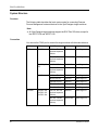
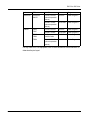
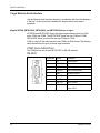
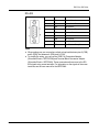
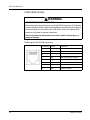
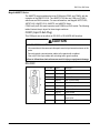
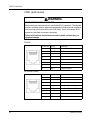
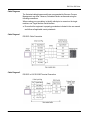
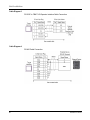
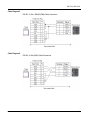
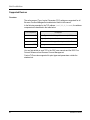
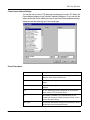
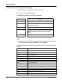
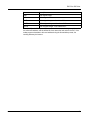
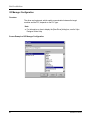
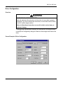
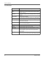
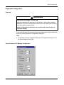
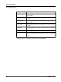
EIO0000001145 03/2012
Emerson Process Management
ROC Plus SIO Driver
EIO0000001145.01
03/2012
www.schneider-electric.com
2
EIO0000001145 03/2012
Table of Contents
Safety Information . . . . . . . . . . . . . . . . . . . . . . . . . . . . .
About the Book . . . . . . . . . . . . . . . . . . . . . . . . . . . . . . . .
Chapter 1 ROC Plus SIO Driver. . . . . . . . . . . . . . . . . . . . . . . . . . . .
5
7
9
System Structure. . . . . . . . . . . . . . . . . . . . . . . . . . . . . . . . . . . . . . . . . .
Target Machine Serial Interface . . . . . . . . . . . . . . . . . . . . . . . . . . . . . .
Cable Diagrams. . . . . . . . . . . . . . . . . . . . . . . . . . . . . . . . . . . . . . . . . . .
Supported Devices . . . . . . . . . . . . . . . . . . . . . . . . . . . . . . . . . . . . . . . .
Device Address Configuration
I/O Manager Configuration . . . . . . . . . . . . . . . . . . . . . . . . . . . . . . . . . .
Driver Configuration . . . . . . . . . . . . . . . . . . . . . . . . . . . . . . . . . . . . . . .
Equipment Configuration. . . . . . . . . . . . . . . . . . . . . . . . . . . . . . . . . . . .
10
12
16
19
20
25
26
28
EIO0000001145 03/2012
3
4
EIO0000001145 03/2012
Safety Information
§
Important Information
NOTICE
Read these instructions carefully, and look at the equipment to become familiar with
the device before trying to install, operate, or maintain it. The following special
messages may appear throughout this documentation or on the equipment to warn
of potential hazards or to call attention to information that clarifies or simplifies a
procedure.
EIO0000001145 03/2012
5
PLEASE NOTE
Electrical equipment should be installed, operated, serviced, and maintained only by
qualified personnel. No responsibility is assumed by Schneider Electric for any
consequences arising out of the use of this material.
A qualified person is one who has skills and knowledge related to the construction
and operation of electrical equipment and its installation, and has received safety
training to recognize and avoid the hazards involved.
6
EIO0000001145 03/2012
About the Book
At a Glance
Document Scope
This manual describes the device driver communication settings in the Vijeo
Designer screen editing software. Vijeo Designer enables you to design Magelis
target machines that communicate with PLCs, drives, field devices, and other
equipment.
For more information about Vijeo Designer and Magelis target machines, please
refer to Vijeo Designer user documentation.
Validity Note
The data and illustrations found in this book are not binding. We reserve the right to
modify our products in line with our policy of continuous product development. The
information in this document is subject to change without notice and should not be
construed as a commitment by Schneider Electric.
Documentation Conventions
Target Machine: Human-Machine Interface (HMI) that runs user applications
designed in Vijeo Designer screen editing software. A target machine is also known
as a terminal.
EIO0000001145 03/2012
7
Product Related Information
WARNING
LOSS OF CONTROL
z
z
z
z
The designer of any control scheme must consider the potential failure modes
of control paths and, for certain critical control functions, provide a means to
achieve a safe state during and after a path failure. Examples of critical control
functions are emergency stop and overtravel stop.
Separate or redundant control paths must be provided for critical control
functions.
System control paths may include communication links. Consideration must be
given to the implications of unanticipated transmission delays or failures of the
link.*
Each implementation of a Magelis XBTGT, HMISTO, HMISTU, HMIGTO,
XBTGH, XBTGK, XBTGC, iPC, and XBTGTW must be individually and
thoroughly tested for proper operation before being placed into service.
Failure to follow these instructions can result in death, serious injury, or
equipment damage.
* For additional information, refer to NEMA ICS 1.1 (latest edition), “Safety
Guidelines for the Application, Installation, and Maintenance of Solid State Control.“
User Comments
We welcome your comments about this document. You can reach us by e-mail at
[email protected].
8
EIO0000001145 03/2012
ROC Plus SIO Driver
EIO0000001145 03/2012
ROC Plus SIO Driver
1
Subject of this Chapter
This chapter explains Emerson Process Management’s ROC Plus SIO driver.
What's in this Chapter?
This chapter contains the following topics:
Topic
EIO0000001145 03/2012
Page
System Structure
10
Target Machine Serial Interface
12
Cable Diagrams
16
Supported Devices
19
Device Address Configuration
20
I/O Manager Configuration
25
Driver Configuration
26
Equipment Configuration
28
9
ROC Plus SIO Driver
System Structure
Overview
The following table describes the basic system setup for connecting Emerson
Process Management’s external devices to the Vijeo Designer target machines.
Note:
z
All Vijeo Designer target machines support the ROC Plus SIO driver, except for
the XBTGT1100 and XBTGT1130.
Connection
You can use the COM1 port to connect the target machine with the external device.
Series
CPU
Link I/F
Comm.
Diagram
ROC
ROC 300
LOI Port, EIA-232
(optional expansion
module
RS-232C
Cable Diagram 1
EIA-485 / RS-485
(optional expansion
module)
RS-422/485
Cable Diagram 4
ROC 800 (809,
827)
LOI RS-232D Port
RS-232C
Cable Diagram 2
EIA-485 / RS-485
(optional expansion
module)
RS-422/485
Cable Diagram 4
DL8000
LOI Port. EIA-232
RS-232C
Cable Diagram 2
Built-In EIA-232
RS-232C
Cable Diagram 1
Optional EIA-232
RS-232C
Cable Diagram 1
ROCPAC
10
ROCPAC 306
ROCPAC 312
ROCPAC 364
EIA-422 / 485 2-Wire RS-422/485
Cable Diagram 5
EIA-422 / 485 4-Wire RS-422/485
Cable Diagram 6
LOI Port, EIA-232
(optional expansion
module)
RS-232C
Cable Diagram 1
EIA-485 / RS-485
(optional expansion
module)
RS-422/485
Cable Diagram 4
EIO0000001145 03/2012
ROC Plus SIO Driver
Series
CPU
Link I/F
Comm.
Diagram
Rosemount
Rosemount
3095FC
LOI Port, EIA-232
(optional expansion
module)
RS-232C
Cable Diagram 2
EIA-485 / RS-485
(optional expansion
module)
RS-422/485
Cable Diagram 4
FB103
FB107
LOI Port, EIA-232
RS-232C
Cable Diagram 1
EIA-485 / RS-485
RS-422/485
Cable Diagram 4
FB407
FB503
FB504
LOI Operator
Interface Cable
RS-232C
Cable Diagram 3
EIA-485 / RS-485
(optional expansion
module)
RS-422/485
Cable Diagram 4
FloBoss
For any other ROC Plus equipment, refer to the manufacturer’s documentation to
determine the pin layout.
EIO0000001145 03/2012
11
ROC Plus SIO Driver
Target Machine Serial Interface
Use the following serial interface diagrams in combination with the cable diagrams
in Section 3 to wire connections between the target machine and external
equipment.
Magelis XBTGK, XBTGC2000, XBTGH2000, and XBTGT2000 Series or higher
All XBTGK and XBTGT2000 Series and higher target machines have two COM
ports: COM1 and COM2. The XBTGC2000 Series has one COM port: COM1.
XBTGH2000 Series (Junction Box) has one COM port: COM1.
COM1 is a 9-pin D-Sub male connector and COM2 is an RJ45 socket. The following
tables illustrate the pin layout for these target machines.
COM1 (9-pin D-Sub Plug)
This COM port can act as either an RS-232C or RS-422 interface.
RS-232C
12
Pin Number Symbol
Description
1
CD
Carrier Detect
2
RD(RXD)
Receive Data
3
SD(TXD)
Transmit Data
4
ER(DTR)
Data Terminal Ready
5
GND
Common Ground
6
DR(DSR)
Data Set Ready
7
RS(RTS)
Request to Send
8
CS(CTS)
Send Possible
9
CI(RI)
Called status display or +5V ±5%
output 0.25A
EIO0000001145 03/2012
ROC Plus SIO Driver
RS-422
Pin Number Symbol
Description
1
RDA
Receive Data A
2
RDB
Receive Data B
3
SDA
Send Data A
4
ERA
Data Terminal Ready A
5
GND
Common Ground
6
CSB
Send Possible B
7
SDB
Send Data B
8
CSA
Send Possible A
9
ERB
Data Terminal Ready B
Note:
z
z
EIO0000001145 03/2012
When making your own connections, attach a loop back between pins 6 (CSB)
and 9 (ERB), and between 4 (ERA) and 8 (CSA).
To simplify the wiring, you can use the COM Port Conversion Adapter
(Schneider Electric: XBTZGCOM) and Terminal Block Conversion Adapter
(Schneider Electric: XBTZG949). These accessories allow access to the RS422 signals using screw terminals. For information on the signals of the screw
terminals, see the user manual for the XBTZG949.
13
ROC Plus SIO Driver
COM2 (RJ45 Socket)
WARNING
UNINTENDED EQUIPMENT OPERATION
When making your own connections, use shielded RJ45 connectors. The shielded
connector provides isolation against electromagnetic interference and provides a
more secure physical connection in the RJ45 socket. Use of an improper RJ45
connection could lead to insecure connections.
Failure to follow these instructions can result in death, serious injury, or
equipment damage.
COM2 supports RS-422/485 signals only.
Pin Number Symbol
Description
1
2
3
4
D1(+)
Send Data (Positive Signal)
5
D0(-)
Send Data (Negative Signal)
GND
Common Ground
6
7
8
14
EIO0000001145 03/2012
ROC Plus SIO Driver
Magelis HMIGTO Series
The HMIGTO target machines have two COM ports (COM1 and COM2), with the
exception of the HMIGTO1310. The HMIGTO1310 has one COM port (COM1),
which uses an RJ45 connector. For more information, see Magelis XBTGT1000,
XBTGT1005, HMIGTO1310, HMISTO, and HMISTU Series.
COM1 is a 9-pin D-Sub male connector, and COM2 is an RJ45 socket. The following
tables illustrate the pin layout for these target machines.
COM1 (9-pin D-Sub Plug)
This COM port can act as either an RS-232C or RS-422/RS-485 interface.
CAUTION
LOSS OF COMMUNICATION
z
z
z
All connections to the communication ports must not put excessive stress on the
ports.
Securely attach communication cables to the panel wall or cabinet.
Use only D-Sub 9-pin cables with a locking tab in good condition.
Failure to follow these instructions can result in injury or equipment damage.
RS-232C
EIO0000001145 03/2012
Pin Number Symbol
Description
1
CD
Carrier Detect
2
RD(RXD)
Receive Data
3
SD(TXD)
Transmit Data
4
ER(DTR)
Data Terminal Ready
5
SG
Signal Ground
6
DR(DSR)
Data Set Ready
7
RS(RTS)
Request to Send
8
CS(CTS)
Send Possible
9
CI(RI/VCC)
Called status display or +5V ±5%
output 0.25A
Shell
FG
Frame Ground (Common with SG)
15
ROC Plus SIO Driver
Note:
z
z
You can switch pin 9 between RI and VCC via software. The VCC output is not
protected against overcurrent. To prevent damage or a unit malfunction, use
only the rated current.
You can use the Cable Connector (Omron Corporation: XMD-0901), Cable
Cover (Omron Corporation: XM2S-0913), and Jack Screw #4-40 UNC (Omron
Corporation: XM2Z-0073).
COM2 (RJ45 Socket)
WARNING
UNINTENDED EQUIPMENT OPERATION
When making your own connections, use shielded RJ45 connectors. The shielded
connector provides isolation against electromagnetic interference and provides a
more secure physical connection in the RJ45 socket. Use of an improper RJ45
connection could lead to insecure connections.
Failure to follow these instructions can result in death, serious injury, or
equipment damage.
COM2 supports RS-422/485 signals only.
16
Pin Number Symbol
Description
1
NC
–
2
NC
–
3
NC
–
4
Line A
Transfer Data (RS-485)
5
Line B
Transfer Data (RS-485)
6
RS(RTS)
Request to Send
7
NC
–
8
SG
Signal Ground
EIO0000001145 03/2012
ROC Plus SIO Driver
DANGER
ELECTRIC SHOCK
The serial port is not isolated. The SG (signal ground) and FG (frame ground)
terminals are connected inside the unit.
When using the SG terminal to connect an external device to the panel:
z
z
Verify that a short-circuit loop is not created when you set up the system.
Connect the #8 SG terminal to remote equipment when the host (PLC) unit is
not isolated. Connect the #8 SG terminal to a known reliable ground connection
to reduce the risk of damaging the circuit.
Failure to follow these instructions can result in death or serious injury.
Magelis XBTGT1000, XBTGT1005, HMIGTO1310, HMISTO, and HMISTU Series
XBTGT1000, XBTGT1005, HMIGTO1310, HMISTO, and HMISTU Series machines
come with one COM port which uses an RJ45 connector. The RJ45 socket closest
to the power connector is the COM1 port. This COM port can act as an RS-422/485
interface.
EIO0000001145 03/2012
17
ROC Plus SIO Driver
COM1 (RJ45 Socket)
WARNING
UNINTENDED EQUIPMENT OPERATION
When making your own connections, use shielded RJ45 connectors. The shielded
connector provides isolation against electromagnetic interference and provides a
more secure physical connection in the RJ45 socket. Use of an improper RJ45
connection could lead to insecure connections.
Failure to follow these instructions can result in death, serious injury, or
equipment damage.
RS-232C
Pin Number Symbol
Description
1
RD(RXD)
Receive Data
2
SD(TXD)
Transmit Data
GND
Common Ground
3
4
5
6
7
8
RS-422/485 (2-wire)
Pin Number Symbol
Description
1
2
3
4
D1(+)
Send Data (Positive Signal)
5
D0(-)
Send Data (Negative Signal)
GND
Common Ground
6
7
8
18
EIO0000001145 03/2012
ROC Plus SIO Driver
Cable Diagrams
The illustrated cable diagrams and those recommended by Emerson Process
Management may differ. However, Schneider Electric recommends using the
following connections.
When creating your own cables, to identify which pins to connect on the target
machine, see Target Machine Serial Interface.
z
Ensure that the equipment is properly grounded as indicated in the user manual
and follows all applicable country standards.
Cable Diagram 1
RS-232C Cable Connection
Cable Diagram 2
RS-232C to LOI RS-232D Terminal Connection
EIO0000001145 03/2012
19
ROC Plus SIO Driver
Cable Diagram 3
RS-232C to FB407 LOI Operator Interface Cable Connection
Cable Diagram 4
RS-485 Cable Connection
20
EIO0000001145 03/2012
ROC Plus SIO Driver
Cable Diagram 5
RS-422, 2-Wire / RS485 (DB9) Cable Connection
Cable Diagram 6
RS-422, 4-Wire (DB9) Cable Connection
EIO0000001145 03/2012
21
ROC Plus SIO Driver
Supported Devices
Overview
The entire range of Type, Logical, Parameter (TLP) settings are supported for all
Emerson Process Management models/series listed in this manual.
In the following example for the TLP address [PLC1]92,0,3:UINT8, the address
components are described in the table below.
TLP Component
Description
92
=
Point Type value for 92 Logon Parameters (LOGON)
0
=
Logical (location) value for 1
3
=
Parameter value for keypad Security Level - Write Enabled
UINT8
=
Data type
You can find details on each TLP in the ROC user manuals and the ROC Plus
Protocol Reference from Emerson Process Management.
Custom TLPs are also supported for point types and parameters outside the
standard set.
22
EIO0000001145 03/2012
ROC Plus SIO Driver
Device Address Configuration
Overview
WARNING
UNINTENDED EQUIPMENT OPERATION
Read and understand the instructions in this section to ensure data is properly
transferred. If you do not follow these instructions, incorrect data could be written
to the PLC and the target machine.
Failure to follow these instructions can result in death, serious injury, or
equipment damage.
To set up a PLC variable, use Input Address Settings or Custom Input Address
Settings.
Input Address Settings
To enter the device address, in the [Variable Properties] dialog box, select the ROC
driver in the ScanGroup property. Then click the ellipsis beside the Device Address
text box to open the following address settings dialog box.
EIO0000001145 03/2012
23
ROC Plus SIO Driver
Screen Description
24
Area
Description
Point Type
A list that contains the point types available from the ROC
database. Select a point type from the list.
Location
A point type location. Enter an integer from 0 to 255.
Slot
The slot number for the physical point type. This property
displays only if you selected a physical slot type. Enter an
integer from 0 to 255.
Channel
The channel number for the physical point type. This property
displays only if you selected a physical slot type. Enter an
integer from 0 to 255.
Parameter
Select a parameter for the point type. Parameters vary
depending on the point type selected.
TLP
The TLP address string that corresponds to the selections
above.The TLP property is read only.
Bit
This property is available if you selected BOOL for the
variable type and only for certain point types. Select a value
from the drop-down list box.
Data Type
This property indicates the data type of the parameter
selected above and is read only.
EIO0000001145 03/2012
ROC Plus SIO Driver
Custom Input Address Settings
You can also set up custom TLP addresses by entering the numeric TLP data in the
Device Address property in the [Variable Properties] dialog box. Or you can click the
ellipsis beside the Device Address text box to open the following address settings
dialog box and then selecting the Custom point type.
Screen Description
EIO0000001145 03/2012
Area
Description
Point Type
A list that contains the point types available from the ROC
database. Select Custom from the list.
Location
When Custom point type is selected, no Location properties
display.
Parameter
When Custom point type is selected, no parameters are
displayed.
TLP
The TLP address string that corresponds to the selections
above. Enter the TLP in numeric format.
Bit
This property is available if you selected BOOL for the
variable type and only for certain point types. Select a value
from the drop-down list box.
Data Type
This property indicates the data type of the parameter. Select
the data type from the drop-down list box.
25
ROC Plus SIO Driver
Valid Formats for Custom Input Address Settings
In the TLP property, enter the TLP. The valid formats are:
z
[PLC1]TT,LL,PP:DATATYPE
[PLC1]TT,LL,PP.BIT:DATATYPE
z
The addresses represent the following components:
TLP Component
Description
[PLC1]
=
External device
TT
=
Point Type (range 0 to 255)
LL
=
Logical (range 0 to 255)
PP
=
Parameter (range 0 to 255)
BIT
DATATYPE
Bit range 0-7, 0-15, or 0-31. Available only for the following
data types: BIN, INT8, INT16, INT32, UINT8, UINT16,
UINT32.
=
Data type
Note:
z
If you entered a custom TLP that matches a TLP in the Emerson database, the
TLP will revert to the address and data type in the database.
The following table lists valid Data Type strings you can enter in the Device Address
property.
Name
26
Description
AC1
ASCII 1 character
AC3
ASCII 3 characters
AC7
ASCII 7 characters
AC10
ASCII 10 characters
AC12
ASCII 12 characters
AC20
ASCII 20 characters
AC30
ASCII 30 characters
AC40
ASCII 40 characters
BIN
Binary 8 bit, or bit address 0-7*
FL
Floating Point
INT8
8 bit signed integer, or bit address 0-7*
INT16
16 bit signed integer, or bit address 0-15*
INT 32
32 bit signed integer, or bit address 0-31*
EIO0000001145 03/2012
ROC Plus SIO Driver
Name
Description
TIME
32 bit signed integer
TLP
24 bit integer in 32 bits
UINT8
8 bit unsigned integer, or bit address 0-7*
UINT16
16 bit unsigned integer, or bit address 0-15*
UINT32
32 bit unsigned integer, or bit address 0-31*
* Read-modify-write. When you write to one of these bit addresses, the target machine reads
the entire word address, sets the defined bit, then returns the new value to the PLC. If the
ladder program writes data to this word address during the bit read/write process, the
resulting data may be incorrect.
EIO0000001145 03/2012
27
ROC Plus SIO Driver
I/O Manager Configuration
Overview
The driver and equipment, which enable communication between the target
machine and the PLC, depends on the PLC type.
Note:
z
For information on how to display the [New Driver] dialog box, see the Vijeo
Designer Online Help.
Screen Example of I/O Manager Configuration
28
EIO0000001145 03/2012
ROC Plus SIO Driver
Driver Configuration
Overview
WARNING
UNINTENDED EQUIPMENT OPERATION
Read and understand the instructions in this section to ensure data is properly
transferred. If you do not follow these instructions, incorrect data could be written
to the PLC and the target machine.
Failure to follow these instructions can result in death, serious injury, or
equipment damage.
To configure the communication settings of the serial driver in the target machine,
use the [Driver Configuration] dialog box. Make sure the settings match those of the
driver.
Screen Example of Driver Configuration
EIO0000001145 03/2012
29
ROC Plus SIO Driver
Screen Description
Area
30
Description
Manufacturer
Displays the name of the driver’s manufacturer.
Driver
Displays the type of serial connection used to connect the target
machine to the driver.
COM Port
Defines which COM port to use on the target machine to connect to
the driver.
Serial Interface
Defines the serial connection.
For details about the supported connections, see Cable Diagrams.
Flow Control
Defines the signals that control the data flow.
Transmission Speed
Sets the communication speed in bits per second. This setting must
match the driver’s baud rate.
Retry Count
Defines the number of times the driver tries to send or receive data
when an error has been detected.
Parity Bit
Detects communication errors, which can be None, Even, or Odd.
Stop Bit
Defines the stop bit, which can be 1 or 2 bits.
Data Length
Defines the length of each unit of data, which can be 7 or 8 bits.
Rcv. Time Out
Defines the length of time (in seconds) the target machine waits for
a response before it outputs a timeout error or sends another
communication.
TX Wait Time
Defines the number of milliseconds that the target machine waits,
after receiving a communication packet, before sending a response.
EIO0000001145 03/2012
ROC Plus SIO Driver
Equipment Configuration
Overview
WARNING
UNINTENDED EQUIPMENT OPERATION
Read and understand the instructions in this section to ensure data is properly
transferred. If you do not follow these instructions, incorrect data could be written
to the driver and the target machine.
Failure to follow these instructions can result in death, serious injury, or
equipment damage.
To set up details about the communication process between the target machine and
the driver, use the [Equipment Configuration] dialog box.
Note:
z
For information on how to display the [Equipment Configuration] dialog box, see
the Vijeo Designer Online Help.
Screen Example of I/O Manager Configuration
EIO0000001145 03/2012
31
ROC Plus SIO Driver
Screen Description
Area
Description
Host Address
The communication address of the target machine. Enter a value
from 1 to 255.
Host Group
The communication group of the target machine. Enter a value from
0 to 255.
Device Address
The communication address for the specific ROC. Enter a value
from 1 to 255
Device Group
The communication group for the specific ROC. Enter a value from
0 to 255.
Operator ID*
The login ID defined for the ROC. Enter a maximum of 3 characters
with no spaces.
Password*
The password defined for the ROC. Enter a value from 0-9999.
Access Level*
Select the check box to define the security access level for the
operator. Select the access level, from 0 to 5, in the corresponding
text box.
* Login Request settings (Operator ID, Password, and Access Level) must match the
settings on the ROC. If the settings do not match, an error will display.
32
EIO0000001145 03/2012