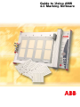
1
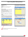
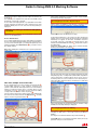
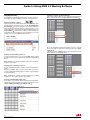
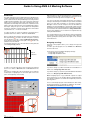
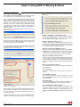
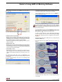
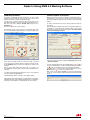
Guide to Using AMS
4.0 Marking Software
Guide to Using AMS 4.0 Marking
Software
Contents
System Requirements............................................................................................................... 2
Software Installation................................................................................................................. 2
Selecting the Output Device and Changing Settings............................................................. 2
Definitions.................................................................................................................................. 3
Getting used to the Software................................................................................................... 4
Create a new project................................................................................................................... 4
Open an existing project............................................................................................................. 4
Selecting tags / marking elements.............................................................................................. 4
Marking the selected tags / marking elements........................................................................... 5
One-time, multiple and serial modes.......................................................................................... 6
Importing files.............................................................................................................................. 7
Row labeling................................................................................................................................ 8
Marking of endless strips............................................................................................................ 8
Copying functions..................................................................................................................... 10
Zoom function........................................................................................................................... 11
Preferences............................................................................................................................... 11
No. of projects and base plates allowed................................................................................... 11
Information menu > ?................................................................................................................ 12
Starting the Print Job with the Plotter................................................................................... 12
Scale Factor............................................................................................................................. 14
Designing new Tags................................................................................................................ 14
Example for same sized tags.................................................................................................... 15
Example for different sized tags................................................................................................ 16
Engraving Tags........................................................................................................................ 17
Engraving with VP 500 Engraver............................................................................................... 17
Starting the Engraving............................................................................................................... 18
Calibrating the Plotter............................................................................................................. 20
Firmware update of the plotter.............................................................................................. 20
1SNC 160 001 M0301
Guide to Using AMS 4.0 Marking Software
System Requirements
Pentium II PC (200 MHz or higher)
64 MB RAM
CD-ROM drive
VGA graphics adapter and monitor (256 colors, resolution
640 x 480)
Operating system: Windows 98, ME, NT, 2000, XP
Mouse
If you like to connect another output device in the future, like the
plotter (half size) Engraver, you can always get back to the window
from the menu bar > File and choose > New. The plotter is default
set as standard output device, connected through the USB.
In addition, the plotter has a parallel port, to be used with the
software.
Software Installation
First close all other applications. Insert the software CD into the
CD-ROM drive of your PC. The installation will start automatically.
Please follow the on-screen instructions.
If the auto-start feature has been switched off on your PC, please
start the set-up program by double-clicking.
When the installation is complete, connect the plotter to the PC
with the parallel interface cable or USB cable and switch the
plotter on.
Selecting the Output Device and Changing
Settings
Now start the program by a double click on the symbol located
on the desktop.
Before working with the software, you must first install the plotter
you intend to use. To do this, select the output device in the window.
As example, if you are using the plotter select the output device
and check the click box as Use always this type of Printer 1 . You
will not be asked any more in the future. With the button Accept 2
the setting will be saved and the window be closed.
For using you need to change the output to parallel, go to
the main menu bar > Output > Output device and check the
Interface tab 3 .
Confirm LPT1 4 as the new interface port and click on Apply.
Connect the parallel cable on both ends and switch on the plotter,
the software will recognize the plotter accordingly.
3
4
1
2
If you click this box, you set the plotter you want to use. Once selected,
you cannot return to back.
1SNC 160 001 M0301
Guide to Using AMS 4.0 Marking Software
Definitions
1SNC 160 001 M0301
Guide to Using AMS 4.0 Marking Software
Getting Used to the Software
Our prime concern when developing this software was that users
should be able to carry out all labeling jobs quickly and easily.
For this reason, every task follows the same basic pattern:
shown on the screen together with the available marker cards.
If you confirm with No, all available elements and manufacturer
2
• Create a new Project
• Open an existing Project
• Selecting tags / marking elements
• Marking the selected tags / marking elements
• One-time, multiple and serial modes
• Importing files
• Row labeling
• Marking of endless strips
• Copying functions
• Zoom function
are presented in the list to be selected from
2
.
After changing the support plate on the plotter or after deleting
a segment within the software, you could click on the icon
Rescan support plates and read the new support
plates.
• Preferences
• No. of projects and base plates allowed
• Information menu > ?
Create a new Project
The plotter has an integrated support plate recognition system
included. The software reads the code of each field, starting
with the left support plate. Assuming the plotter is turned on,
the communication cable is connected and support plates are
placed on the plotter itself, the software pre-selects the marker
cards already.
If you click on the icon New Project of the menu bar, or select
> File and > New from the main menu, the message comes up,
if you like to use the recognition system and read the support
plates.
After you confirm with Yes 1 , the support plates are recognized and
1
1SNC 160 001 M0301
Open an existing Project
If you click on the icon Open Project of the menu bar, or select
> File and > Open from the main menu, existing projects could
be loaded.
You are able to work with up to 10 different projects at the same
time and could use all the Copy and Paste functions between
them.
Selecting tags / marking elements
After you double click on one of the segments on the screen, a
list of the available marker you can work with and select from
comes up 3 .
Just choose the type you have placed on the support plate and
the selection will be presented on the screen.
3
3
Guide to Using AMS 4.0 Marking Software
If the no. of marker presented are not sufficient in order to complete
your job on one base plate (holding up to 4 support plates), new
base plates with respective support plates could be added upon
your convenience.
In order to do so, please select > Edit and > Add Plate
the main menu or use the right mouse button.
4
from
Marking the selected tags / marking elements
Double-click the tag or element where the labeling process is to
begin. This opens the labeling dialog box, which contains all the
setting options.
In order to open the edit window, please click on the first tag to
start with, use the right mouse button and choose > Labeling
from the menu or start typing a character on the keyboard (check
under > Option from the menu first).
The exact description of the selected tag and the number of tags
available both appear in the top line of the dialog box 5 .
An outline of the selected marking element is shown in the top
third of the box 6 . Angle and text alignment options are found
next to this diagram 7 . The number of lines per tag can also be
specified here 8 .
Note that the program will only allow options that are appropriate
for the selected element.
The various tabs for different methods of data input and import
appear in the middle of the box 9 . This is where you can enter
all the data and text for one-time, multiple, and serial marking,
and files to be imported from different programs, as well as text
for custom labeling (for example, row labeling).
4
The font, font width, font size, line spacing, tip width of the plotter
pen, and plotting speed settings can be adjusted in the lower
part of the box 10 .
The values match the chosen marking element, but can be altered
within reasonable limits.
5
A new blank base plate comes up to be used with more segments.
Up to 16 base plates could be used in one project (max. 10
projects in one file).
To move from one base plate to the other just click on their names
in the lower left corner. Base plates could also be renamed just
with a double click, or moved in the position to each other with
drag and drop.
7
8
6
9
10
1SNC 160 001 M0301
Guide to Using AMS 4.0 Marking Software
A warning message is displayed if text length exceeds the size
of the tag 1 .
This enables you to adjust the font, font size or font width so that
the text fits onto the tag or element.
From a certain font height upward, only capital letters and certain
special characters are allowed in order to make best use of the
available labeling area. In such cases the following warning is
displayed:
If the number of repetitions exceeds the number of tags available,
the following warning is displayed:
Not enough tags selected to fit your request
and the number of repetitions must either be corrected or more
tags must be provided for labeling by confirming with Yes.
Only upper case letters, special characters and symbols
are allowed
Characters as "g, j, y, Ä, Ö, Ü" are not allowed in order to make
best use of the labeling area.
Restore Default values
If you change parameters (font types, text height, line numbers
etc.) for each element this data will be stored in a separate file. If
you choose the element again, you will find the previously used
parameter settings. Click Default values 2 , if you want to restore
the original settings.
Clicking OK transfers the labeling to the tags.
If sequential numbering is to be carried out, after selecting the
number of lines you must specify the line in which the sequential
numbering is to appear. To allow this, the Series check box
to the right of the line is activated 7 . Checking this box then
activates the Consecutive no. button 8 and prevents input in
the editing field.
Clicking the Consecutive no. button opens a further window,
allowing serial marking to be entered 9 .
Note: After updating the software the user's specific parameters
remain valid.
2
7
8
1
Here the start value, final value, preceding text (prefix), following
text (suffix), step size, counting method, and number of repetitions
can be entered, the counting method can be chosen to be in
ascending order. The count could be chosen in decreasing nos.
(start value higher than final value) or increasing nos. (start value
lower than final value).
One-time, multiple and serial modes
By choosing the tab for one-time, multiple, and serial modes 3 ,
corresponding sequences of text, numbers, characters and
symbols can be entered. At the right-hand corner of the marking
window you will find a large choice of symbols which can be
selected by a click 4 . The number of lines opened for editing
corresponds to the number of lines set per tag 5 .
Text can now be entered. The number of tags to be labeled with
the same text should be entered in the Repeat field 6 . The data
input is shown in the preview window 7 .
9
10
4
3
7
If the series labeling job specified exceeds the number of tags
available, the following warning is displayed:
Not enough tags marked for labeling
5
6
The number of tags must either be reduced for example, by
changing the final value or more tags must be provided for
labeling.
The sequences entered are listed in the preview window 10 .
Clicking OK returns you to the previous window, and any necessary
parameter changes can be made there.
1SNC 160 001 M0301
Guide to Using AMS 4.0 Marking Software
Clicking OK again transfers the labeling to the tags.
You can edit the data in the preview window. It is possible to delete
texts, insert empty rows and special symbols or other texts 11 .
Note: If you want to insert more data in series, sequences cannot
be shown and edited in the series modus.
13
11
You can now copy either part or all of the table and use it for
marking.
Please follow these steps:
Use the mouse to select individual or multiple cells, individual
or multiple columns, individual or multiple rows 14 , and click the
Copy marked range button 15 .
Importing files
After choosing the Import file tab, data can be imported from other
files. Data can be imported from other CAD/CAE programs, text
files, or spreadsheet programs.
An efficient import function is available to allow extraction of the
required data from a range of file formats.
14
Clicking the Browse button 12 makes it possible to locate the file
to be imported. Click to select the file name, and then click Open
to access the file for importing.
15
12
A window will now open displaying the data for importing, in table
format. The default separators are "space" and "tab" sign. If the
table is divided up in such a way that the data cannot be copied,
you can reset one or both of the default separators by a click. You
can also select and preview another separator in the combo box
list 13 until you find a suitable setting, or enter your own sign.
The data will be inserted into the editing field 16 , and you can
check whether the copied data is correct. It is possible to edit the
data in this window, like input of new data, delete data, correct
data and copy data.
16
The original setting can be restored at any time.
If you want to import an Excel, an Access or an E-Plan file, the
program will automatically recognize the format and open the first
worksheet for importing. This is the default setting. You can also
select other sheets from the file.
1SNC 160 001 M0301
Guide to Using AMS 4.0 Marking Software
The following functions exist to aid data import
1
:
Overwrite existing data
If you enable this function, newly copied data will automatically
overwrite previously copied data. If this function has not been
enabled, the data will be appended to the existing data.
Ignore null values
If this function is enabled, cells containing no data will not be
imported.
Left to Right
This function allows the import sequence to be changed. In the
default setting, the data is transferred by column from top to bottom.
If the left-to-right function is enabled, the data is transferred by
row from left to right.
1
2
The import filter is specially designed for the import of files created
by former software programs, supporting a direct import of a
complete marker card. There is no “select from” available, the
file is recognized and opened in the background upon importing
the data. The software opens the dedicated segment on a new
base plate and transfers the labeling to the tags accordingly. Post
import of the data, all edit functions can be used as previously
described.
Special import formats are available at sales support.
Row labeling
After choosing the row labeling tab, marking can be easily carried
out on individual row.
Please ensure that you have selected complete row, since otherwise
proper labeling will not be possible.
The editing field 3 is used to enter the text to be printed on the
row. The characters for each tag must be separated by commas
for example, “ab, cd, ef, symbol, symbol” means print “ab” on the
first tag, “cd” on the second tag, “ef” on the third tag, "symbol"
on the forth tag and "symbol" on the fifth tag.
Clicking OK transfers the labeling to the tags.
3
Data can also be easily imported from files using Copy and Paste
and the Windows Clipboard.
To do this, open the relevant file and copy the data to the
Clipboard. When the original file has been closed, the data on
the Clipboard can be pasted into the editing field on the righthand side of the import box 2 either by pressing the Ctrl V keys
or by using the shortcut menu which pops up after clicking the
right mouse button.
After the data has been transferred to the preview window, it can
be modified as required. Available functions include deleting data,
inserting data, etc.
Clicking OK transfers the labeling to the tags.
If the number of requested tags exceeds the number of tags
available, the following warning is displayed:
Not enough tags selected to fit your request
and the number of imported tags must either be corrected or
more tags must be provided for labeling.
Another direct import function is available from the main menu,
select > File and > Import file.
Marking of endless strips
This software has special features for marking of endless strips:
Strip partitioning
Marking complete strip
Marking strip section
Copy a strip
Insert a strip
If you choose strip-material, the above mentioned functions for
sectioning and marking of strips are available on the menu >
Edit.
By clicking you can select the strip you wish to mark.
Note: In order to mark a section of strip you have to prepare it
first via menu > Edit > Strip partitioning.
1SNC 160 001 M0301
Guide to Using AMS 4.0 Marking Software
Note: The space available for marking is calculated on the lowest
element-width. Should you request an individual marking on the
various element-widths, please choose this marking possibility
over the menu by selecting > Edit > Marking strip section.
Strip partitioning
You can open a window via > Edit > Strip partitioning which
allows you to divide the strip into various sections 4 . First put in
the width of the strip and then the amount of elements required
in that width and confirm by pressing the button Append .
Thereafter you can select and add further sections with different
widths 5 . If you wish to insert a section between other sections you
have to mark-out the section before which you want to insert.
Marking strip section
Mark-out the strip section you want to work on by clicking. Via
menu > Edit > Marking strip section you can open the labeling
window and can select the print. This function allows you to
completely utilize the available element-width.
Then press the button Insert to start the process.
You can delete sections by marking-out the section and pressing
the Delete button.
At the bottom part of the window you can check strip-length
already occupied 6 and the remaining strip-length 7 .
After completion of sectioning press OK button and the strip will
show up with the corresponding divisions.
Note: Cut markings can be added to the print output. The
settings are made in the print output menu (see chapter “Printing
Tags”).
Copy strip / Insert strip
Mark-out the strip you wish to copy by clicking.
Via menu > Edit > Copy strip 9 you can prepare the copy process.
Now click to the strip onto which you want the data to be inserted.
Via menu > Edit > Paste strip 10 the data will be inserted.
4
5
6
9
10
7
Marking complete strip
Mark-out the required strip by clicking. Via the menu > Edit >
Marking complete strip you can get to the labeling window 8
in which you can select the type of marking.
This function allows you to carry out marking in multiple and serial
mode in various element-widths.
8
1SNC 160 001 M0301
Guide to Using AMS 4.0 Marking Software
Copying functions
To avoid having to repeatedly enter the same or similar sequences,
the program provides a multiple number of copying functions:
Copying a marking sequence
Select a sequence by clicking it with the left mouse button. Now
click the right mouse button and choose > Copy marking (only
tags with text) 1 from the shortcut menu. Then use the left mouse
button to select the element where the copied sequence is to be
inserted. Open the shortcut menu by right-clicking and choose >
Paste marking 2 . If desired, the sequence can be altered. The
copy/paste functions can also be accessed via the icons on the
toolbar or by choosing > Edit from the menu bar.
Copying a complete segment with tags
Choose the segment with a mouse click. Press the right mouse
button, select in the menu > Copy segment and activate it 3 .
3
1
2
Go to the destination segment and click the mouse to activate
it. Press the right mouse button and select in the menu > Paste
segment 4 .
Using the menu bar > Edit and sub menus copy and paste works
in the same way as described above.
Copying several marking sequences
To copy several sequences, you can use the Shift - key to extend
and select the area to be copied. Copy and paste as described
above.
Note: Simultaneous copying of multiple sequences to other types
of tags is not possible.
Copying parts of marking sequences
To copy individual markings from within sequences follow these
steps:
Hold down the Ctrl - key and select all the labels you wish to
copy by clicking them with the left mouse button. Copy and paste
as described above.
Note: Simultaneous copying of partial marking from multiple
sequences to other types of tags is not possible.
Copying of marking with empty signs
If you want to copy a range of tags, including non marked tags,
mark these and click the right mouse button, select in the menu
> Copy marking (including signs without text) 3 .
Copy and paste as described above.
3
10
1SNC 160 001 M0301
4
Guide to Using AMS 4.0 Marking Software
Copying an entire base plate
Choose > Edit from the menu bar, followed by > Copy Plate
5
.
5
Zoom function
In order to activate or deactivate the zoom function, choose > View
> Zoom function from the menu bar or click on the icon.
Click on the icon once and move the mouse to the position on
the base plate you like view differently. With the left mouse click
the position will be taken as new screen center and enlarged. A
new click on the icon will deactivate the function, continuing to
work with the current zoom.
The click with the right mouse button reduces the screen by a
given zoom factor.
Preferences
Choose > Extras > Options from the menu bar for opening the
window to select form.
To select the language please check the next window coming
up 7 .
Before the plot starts a message comes up, reminding you how to
treat the plotter pens. If you don´t like to have it come up please
check the mark 8 .
Choose again > Edit from the menu bar, followed by > Paste
Plate 6 . The whole plate will be copied automatically.
If you select a tag ready for labeling, you can just start to enter the
character on the keyboard as first character accepted, the labeling
window opens and the character is placed on the selected tag. If
you don´t like to have it in place please check the mark 9 .
7
8
6
9
Copying of texts onto other tag sizes
In some cases, the copying function of text to other tag sizes is
disabled. It is only allowed to copy in a common sense. The preview
of the print must fit on the tag, like writing angle and text size.
In general only one sequence can be copied at a time.
Note: All copy functions described can also be used between
projects.
No. of projects and base plates allowed
Choose > Windows from the menu bar in order to receive the
overview of your actual project no. and base plates activated.
In total you can have up to 10 different projects 10 and up to 16
base plates 11 from each project open and work with.
10
11
11
1SNC 160 001 M0301
Guide to Using AMS 4.0 Marking Software
Information menu > ?
Choose > ? from the menu bar to receive further information
about the system.
If you select > ? >Support plates , a window with different
lists comes up, showing the actual available support plates, the
description and part no.
1
If you select > ? >Online-help, a description of general features
of the software is available. You can click within the software at
any time on the icon or open the help file from the menu bar > ?
> Online-Help 2 .
The information window opens from the menu bar > ? > Information
3 with important information about the software version, the
release of the database and the firmware of the plotter. To close
the window, click on the OK button.
1
Following new information are displayed and adjustments could
be selected from:
In the top part of the window the selected plotter and interface
are indicated 4 .
The next click box you can check to activate or deactivate
priming the plotter pen on one of the fields left or right of the
Pen Station.
The next field of the window indicates the recognized support
plates, placed on the plotter. Are those different from the ones
chosen for this project, the necessary support plate for this job
is indicated in red 5 .
The right side of the window is used to show the different plotter
pens to be used for this job, also with a color indication according
to the standard color coding of the plotter pens 6 .
4
2
3
Starting the Print Job with the plotter
Once all the data for printing the job are entered, please click on
the printer icon in the menu bar.
Prior to starting the real print, the software verifies, if the selected
support plates are identical with the ones placed on the plotter,
the recognition system starts to talk to the plotter for short time.
Therefore the plotter needs to be turned on and the data cable
connected.
If the support plates recognized are different from the ones selected
for the job, a warning message comes up on the screen.
If you want to proceed, you need to confirm.
12
1SNC 160 001 M0301
5
6
If the tip of the pen used is larger than .5 mm a message comes
up, telling that the standard pen sizes (.18 mm to .5 mm) for this
job will be different.
Guide to Using AMS 4.0 Marking Software
Different print options could be set up in the lower part of the
window 7 :
If you print on endless strips, additional adjustments are
subject to be checked.
7
8
Use one Plotter Pen Size only
In order to execute this job, two or more pens to be used might
be indicated. If you like to use one tip size, please check this box
and select the respective Pen.
Use Pen inserted in Pen Holder
Once checked this box, no Pen will be picked up from the Pen
Station. The pen directly inserted into the Pen Holder will be used.
This option could be used, if pens used are different from the EKTeam Pens, although they might have a HP compatible outside
dimension, but will not fit into the Pen Station of the plotter.
10
9
Insert a cutting line
No 8 : no cutting line is printed
Yes 9 : cutting lines are printed after each tag length
Final 10 : cutting line is printed after the last tag of the whole
strip length
The print job starts with a click on the OK Button.
The software checks again if the selected support plates are
placed on the plotter. If not, a warning message comes up to be
confirmed, either continue or cancel.
Use one Plotter Speed only
In order to execute this job, different speeds (10 to 40 mm per
second) could be selected from the data entry. In order to work
with one speed selection only, please check this box and select
the respective speed.
Print selected tags only
If you check this box, only the tags marked before are subject
to be printed.
•Select a sequence:
Just click in the edit window on the sequence once and it is
marked.
•Select multiple sequences:
Just click in the edit window on the first sequence once, hold
down the Shift Button and click on the next sequence ones
etc. and all are marked.
•Select single tags:
Hold down the Ctrl Button and just click in the edit window
on the single tag or multiple tags once and they are marked.
Print selected segments only
If you check this box, only the segments marked before are subject
to be printed. Just click in the edit window on the segment once
and it is marked. In order to mark two or more segments, hold
down the Ctrl Button and click on each segment once.
In case the already started job should be stopped, please click
on the icon Stop Plot in the menu bar. The printout will be
interrupted and the data (if any left) in the print spooler of the
PC will be deleted.
The plotter turns into the Stop Mode and the internal buffer of
the plotter can be deleted by pressing the Clear buffer Key 11
on the operation panel.
In order to send a new job to the plotter, the plotter must be turned
back into the active mode by pressing the Stop Key 12 once on
the operation panel, the red light turns off at the plotter panel.
Other plotter connected might be different in the operation, please
refer to the instruction manual.
11
12
13
1SNC 160 001 M0301
Guide to Using AMS 4.0 Marking Software
Scale factor
The data created from each individual tag for the database was
carefully investigated, although they are not frequently checked.
There could be a chance for the printable tags to receive by the time
a slight mechanical deviation, spec. in the scale factor, means the
distance from one tag to the next in both of the directions x and y.
Temperature and humidity at the work bench could influence the
distance as well as new production series and different production
techniques during the process like material and temperature
changes. Covering the complete x and y dimension of the marker
card, deviations of > 1 mm are noticeable.
In order to be able to correct the settings a special function is
provided under menu > Extras > Elements> Scale factor.
Once a segment with a marker card is placed on the plotter the
first upper left tag 1 should be checked, if the print is centered
in both directions (see also chapter "Calibrating the Plotter").
There after the last tag at the lower right corner 2 needs to be
printed in the same manner.
If not printed exactly the same, the scale factor for this particular
card is not perfectly correct.
Scale in x-direction
1
With the button Pen Up /Down the plotter pen or magnifying tool
can be lowered in order to find exactly the correct spot of the
beginning of the last tag at the lower right corner 3 .
You can move the arm of the plotter with the four cursor buttons
in the pre-selected steps from 0.025 mm up to 10 mm, the default
value is 0.1 mm. After completion you must press the button
Accept in order to save the changes to the user file within the
database, the general database is always kept original. Closing
the window moves the plotter arm back to the previous position.
The next start of the software will take the changed information
from the user database. You can return to the original values by
clicking the Reset button.
The complete dimension in x and y direction can be changed with
the correction of the scale factor. Re-check the result of the print
again by printing the last tag at the lower right corner, centered
in both directions.
Designing new Tags
This part of the program allows you to design own tags and
elements.
In order to open the program, choose > Extras and > Elements
from the main menu.
There are two versions available designing new tags:
• Design tags with same size
• Design tags with different sizes
Scale in
y-direction
2
In order to correct the scale factor select one tag on the segment
and choose > Extras > Elements and > Scale factor from the
menu.
The tags are changing into red and the plotter moves with the
inserted pen or magnifying tool to the lower right corner to the
point of the beginning of the last tag.
If you like to design e.g. a label sheet with same sized labels in a
matrix, use > Design tags with same size.
If you like to design e.g. a serial no. plate with different sized label
areas, use > Design tags with different sizes.
Note: Designing tags is only possible with a plotter as output
device selected. If you are working with the engraving feature,
the software suggests to use either the half (DIN A4) or full size
(DIN A3) plotter.
The use of the design program is described below, after saving,
the designed elements are available for labeling in the folder >
User defined under Producer (manufacturer) 4 .
4
3
14
1SNC 160 001 M0301
Guide to Using AMS 4.0 Marking Software
Example for designing a label sheet (matrix) with
same sized labels
8
9
Open the designer from the main menu with > Extras > Elements
> Design tags with same size as described above.
The following window appears:
with a click on the button New a new element can be named in
the window under <Untitled> 5 .
It is useful to work with the element recognition system of the
plotter in order to find the element more easy later on.
For the element you want to design, enter a new name and if you
don´t want to use the element recognition system, select the type
of support plate for the sheet 6 . You can select between a quarter
size, half size or full size support plate.
Pre-selected is the plate for sheets (half size plate).
Further you can select in the lower left part of the window, if
the new designed material is for plotting only or plotting and
engraving 7 .
5
10
11
If you have entered minimum the no. tags (label) in each direction
9 , please click on the Take measurements button.
A new window opens up, providing buttons and entry windows, in
order to take all relevant measurements for the new element.
6
7
Note: Engraving is only possible on dedicated support plates.
Once selected, click on the Edit button.
A new window opens up 8 , where you can enter the data of
the tag (size of the label), if known 10 . You can always take
the measurements using the plotter system, if the data is not
available.
You need only to enter the nos. of tags in x and y direction.
All other data necessary for the program can be taken with the
plotter system.
Please enter the no. of tags in x and y direction as shown in the
window 9 . If available enter also the size of the tag (label) and
the distance to the next tag. You can always correct the data later
on, if the exact nos. are not present at the moment.
Always take the start position of the first tag with the plotter
system!
Please follow the steps for taking measurements:
Determine the exact position of the first tag 12 on the label sheet.
In order to do so, please click on the most left button Initial
position of the window.
The arm of the plotter moves to its upper left corner limit (zero
position). From there you can move the arm with the pen inserted
to the upper left corner of the first tag with the cursor buttons 13 .
You can select the size per step in mm in the upper right area of
the window 14 .
Please check with the Pen Up/Down button 15 the correct
position after you moved the pen to the initial point of the tag.
The respective co-ordinates are shown in real nos. in the x- and
y- window based on the zero position.
12
14
15
13
Further on, you can decide on the labeling direction of the tags.
For the sequence for plotting or engraving you can choose
between upper left to upper right (by row) or upper left and lower
left (by column) 11 .
Attention: It is essential for continuing the design to switch on the
plotter and have the support plate with the label sheet placed on.
Insert a plotter pen directly into the pen holder of the plotter.
15
1SNC 160 001 M0301
Guide to Using AMS 4.0 Marking Software
Determine now the exact position at the lower right corner of
the first tag 1 . Just repeat the steps as for the upper left corner,
described above.
You can find the new element for labeling in the folder > User
defined under Producer 5 .
1
As next step, determine now the exact position of the upper left
corner of the last tag (size of matrix) 2 . Take the initial position
3 in the same manner as described above.
5
2
Note: All new elements in the folder User defined will continue
to be available after program updates.
3
After completion of the three steps all measurements are taken
for the element. In order to save the data for the new element,
please click on Accept.
The window "Take corner measurements of tags" will be closed
and you are back to the previous window.
Example for designing a serial no. plate with
different sized label areas
Open the designer from the main menu with > Extras > Elements
> Design tags with different sizes.
The same window appears, as described before for designing
tags with the same size.
Please click on the button Accept in the window and the new
designed element will be shown. Now you can check, if all the data
where taken correctly. Any up-coming error or warning message
at this point means, please re-check the data manually or allow
the automatic correction by the program.
Click on the button Close
program.
4
in order to terminate the designer
All adjustments will be done in the same manner. After clicking on
the button Edit a similar window appears, just with an additional
function.
Now you have the ability to implement different sized labeling
areas 5 . Each new area or field needs to have an own name.
Taking the measurements is now similar to the previous sample
of the label sheet matrix.
5
4
Note: The new labeling areas could be part of a label sheet (matrix)
as well as a single area.
16
1SNC 160 001 M0301
Guide to Using AMS 4.0 Marking Software
Please click on the button Accept in the previous window and
the new designed element will be shown. Now you can check, if
all the data where taken correctly.
Further adjustments using the engraving tool are available by
clicking on the button Adjustment Engraving Tool 6 .
6
Following adjustments for the engraving unit could be made and
selected from.
Any up-coming error or warning message at this point means,
please re-check the data manually or allow the automatic correction
by the program.
Click on the button Close in order to terminate the designer
program. You can find the new element for labeling in the folder
> User defined under > Producer.
In case the labeling is not exactly centered, you are allowed to
edit the new designed elements at any time. Open the designer
program again, choose the element or part of the element you
want to change and click on the button Edit for making the
adjustments.
Note: All new elements in the folder User defined will continue
to be available after program updates.
Engraving Tags
Please select the output device first in order to start the engraving
with the engraver (see also chapter "Selecting the Output Device
and Changing Settings"). The steps getting used to the software
are not changed using the engraver. Just where the functions are
different or additional a new description is implemented into the
manual as described in the following.
Engraving with the plotter engraver
Double-click the tag or element where the engraving process
is to begin.
This opens the labeling dialog box, which contains all the setting
options. In order to open the edit window, please click on the first
tag to start with, use the right mouse button and choose > Labeling
from the menu (see also chapter "Marking the selected tags /
marking elements") or start typing a character on the keyboard
(check under > Extras > Option from the menu first).
• Size of tool 7
Engraving needle in the size of .2 mm up to 1 mm could be
selected from
• Engraving speed 8
Adjustments of 5 mm/s up to 20 mm/s could be selected
from
• Revolution per minute (RPM) 9
Adjustments of 5,000 up to 50,000 RPM for the engraving spindle
could be selected from
• Penetration speed 10
Adjustments of 0.5 mm/s up to 5 mm/s could be selected from
in steps of .1 mm/s
The type of the tool and the penetration depth will be suggested
according to the selected engraving material 11 .
7
8
9
10
12
11
Restore Default values:
If you change the above parameters for each element the data
will be stored in a separate file. If you choose the element again,
you will find the previously used parameter settings.
Click Default values 12 , if you want to restore the original
settings.
Note: After updating the software the user´s specific parameters
remain valid.
17
1SNC 160 001 M0301
Guide to Using AMS 4.0 Marking Software
Starting the Engraving
Once all the data for engraving the job are entered, please click
on the printer icon in the menu bar (Print / Plot / Engrave).
Various engraving options could be set in the middle part of the
window 4 :
Prior to starting the real engrave, the software verifies, if the VE
500 is connected correctly and switched on and if the selected
support plates are identical with the ones placed on the VP 500
Engraver. The recognition system starts to talk to the VP 500
Engraver for short time. Therefore the VP 500 Engraver needs
to be turned on, the data cable connected and the Controller
VEC 500 and the Vacuum Cleaner VC 500 connected with the
respective cables.
If this is not the case a warning message comes up on the screen,
you need to confirm.
• Only one engraving tool and depth to be used
In order to execute this job, two or more engraving needles to
be used might be indicated. If you like to use one needle size
and penetration depth only, please check this box.
Please re-check the installation with all cable connections and
recycle the power of the VP 500 Engraver. This message pops
up only if the engraving unit is not ready.
If the support plates recognized are different from the ones selected
for the job, a warning message comes up on the screen. If you
want to proceed, you need to confirm.
Following new information are displayed and adjustments could
be selected from:
1
3
2
• Only one engraving speed to be used
In order to execute this job, different engraving speeds (5 to 20
mm per second) could be selected from the data entry. In order
to work with one speed selection only, please check this box
and select the respective engraving speed.
• Only one revolution speed (RPM) to be used
In order to execute this job, different revolution speeds (5000 to
50000 RPM) for the engraving spindle could be selected from
the data entry. In order to work with one selection only, please
check this box and select the respective revolution speed.
• Only one penetration speed to be used
In order to execute this job, different penetration speeds (0.5
mm to 5 mm per second) for the engraving needle could be
selected from the data entry. In order to work with one selection
only, please check this box and select the respective penetration
speed.
• All selected tags will be engraved
If you check this box, only the tags marked before are subject
to be engraved.
4
5
• Select a sequence
Just click in the edit window on the sequence once and it is
marked.
• Select multiple sequences
Just click in the edit window on the first sequence once, hold
down the Shift Button and click on the next sequence ones etc.
and all are marked.
• Select single tags
Hold down the Ctrl Button and just click in the edit window on
the single tag or multiple tags once and they are marked.
In the top part of the window the selected plotter and the used
interface is indicated 1 .
The field below in the window indicates the recognized support
plates, placed on the plotter. Are those different from the ones
chosen for this project, the necessary support plate for this job
is indicated in red 2 .
The right side of the window is used to show the different engraving
needles to be used for this job, also with a color indication 3 .
18
1SNC 160 001 M0301
• All selected segments will be engraved
If you check this box, only the segments marked before are
subject to be engraved. Just click in the edit window on the
segment once and it is marked. In order to mark two or more
segments, hold down the Ctrl Button and click on each segment
once.
Guide to Using AMS 4.0 Marking Software
Various options for the frame are available in the lower part of
the window 5 :
There after the software reminds you by a message to verify, if the
selected engraving needle is inserted into the spindle.
This message needs to be confirmed with a click on the OK Button
and the engraving job starts.
5
6
In case the already started engraving job should be stopped,
please click on the icon Stop Plot in the menu bar. The engraving
will be interrupted and the data (if any left) in the print spooler of
the PC will be deleted.
The VP 500 Engraver turns into the Stop Mode and the internal
buffer of the VP 500 Engraver can be deleted by pressing the
Clear buffer Key 7 on the plotter operation panel.
• Engrave frame around lettering
With this option selected, a frame will be engraved around the
lettering. First the lettering will be engraved. Thereafter the
engraving process stops asking you in a message box to change
the engraving needle or to alter the engraving depth.
All frames around the tags will be engraved, even if they don’t
carry any lettering.
In order to send a new job to the VP 500 Engraver, the plotter
must be turned back into the active mode by pressing the Stop
Key 8 on the operation panel, the red light turns off at the VP
500 panel.
Alternative the power of the VP 500 can be re-cycled by pressing
the OFF and ON button.
All existing data will be deleted and the zero position realigned.
• Engrave frame only
With this option selected, the frame will be engraved only without
the lettering. This selection is useful engraving multiple depths
on thicker material. Using first a lower penetration depth and
for the second run the final setting.
• Round frame corners
With this option selected, you can select in a combo box various
radius settings for the corner engraving of the frame. Possible
settings for the radius are between 1 mm and 5 mm in .5 mm
steps.
7
The engraving job starts with a click on the OK Button. The
software checks again if the selected support plates are placed
on the plotter.
If not, a warning message comes up to be confirmed, either
continue or cancel.
8
For further information, please refer to the operating instructions
of the plotter.
19
1SNC 160 001 M0301
Guide to Using AMS 4.0 Marking Software
Calibrating the Plotter
Firmware update of the plotter
The plotter is calibrated during the production. In case of small
deviations, like the printout is not correctly in the center of the
marker, the plotter could be calibrated manually.
In order to do so, please make sure there are no parts on the
plot field, like ball-pen, not proper mounted support plates etc.,
then go to the menu > Output > Output device and choose >
Calibration 1 .
The arm moves into the center position.
With this option you are able to update the existing firmware of
the plotter. It is necessary e.g. if you are using a plotter already,
purchased in 2005 or earlier and now wanted to use the engraving
feature.
In the window on the screen you have 4 cursor buttons 2 in order
to move the setting in either direction, in steps .025 mm up to
10 mm, the default setting is .1 mm.
In order to download a new version, please follow the steps as
described:
Start the program software and switch on the plotter. Make sure
the plotter is connected with the interface cable to the PC and
the interface is selected correctly (see chapter "Selecting output
device and changing settings").
1
4
5
6
3
2
7
Each click in the button will move the Pen holder connected
to the arm into the desired direction. After the changes made,
hit the Calibrate button and the new settings are stored in the
software.
Please check again during the next print, if necessary use
the calibration function again until the output performance is
satisfied.
Use always the first tag at the upper left corner of the segment
(see also chapter "Scale factor").
The Reset button takes you back to the original setting.
Although the other output devices you might want to use are precalibrated, because of the different starting point, the calibration
procedure as described is essential with those other devices.
20
1SNC 160 001 M0301
Choose from the main menu > Output > Output devices the tab
> Firmware update.
The upcoming window shows the actual firmware in nos 4 . A later
version of the firmware is shown in the field below with a higher
no 5 . Now you can update to the next level of the firmware.
If the later version is not in the pre-selected folder, please use the
Browse button 6 to search for in another folder.
With a click on the button Update 7 a new message window
opens up. You are asked to switch the plotter into the download
mode.
Guide to Using AMS 4.0 Marking Software
In order to do so, turn off the plotter, hold down the button Clear
buffer 8 and the button STOP 9 together and press ON again.
The control LEDs STOP and Clear buffer are on.
8
9
Confirm the setting with the OK button and the update process
starts. A new message opens up telling you the plotter will turn off
automatically after completion. Confirm with the OK button.
In order to check if the new firmware is stored correctly in the
plotter, turn on the plotter again and choose from the main menu
> Output > Output devices the tab > Firmware update. In the
field “Actual firmware version” should now be the no. of the
latest version.
21
1SNC 160 001 M0301
ABB France
Automation Products Division
Export Department
10, rue Ampère Z.I. - B.P. 114
F-69685 Chassieu cedex / France
Tel. : +33 (0)4 7222 1722
Fax :+33 (0)4 7222 1935
1SNC 160 001 M0201
06.2007 - PDF
As part of its on-going product improvement, ABB
reserves the right to modify the characteristics or the
products described in this document.
The information given is not-contractual. For further
details please contact the ABB company marketing
these products in your country.