1
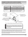
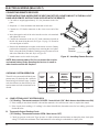
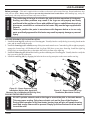
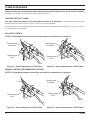
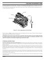
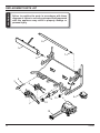
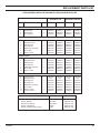
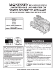
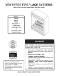
UNVENTED GAS LOG HEATER OR
VENTED DECORATIVE APPLIANCE
INSTALLATION AND OPERATING INSTRUCTIONS
MODELS
DLX18/GLX18
DLX24/GLX24
DLX28/GLX28
Natural Gas or Propane/LPG
Control Type:
Manual, Thermostat or Milli-Volt
WARNINGS
If the information in this manual is not followed exactly,
a fire or explosion may result causing property damage,
personal injury or loss of life.
This is an unvented gas-fired
heater. It uses air (oxygen) from the
room in which it is installed.
Provisions for adequate combustion
and ventilation air must be provided.
Refer to page 7.
–
Do not store or use gasoline or other flammable
vapors and liquids in the vicinity of this or any other
appliance.
–
WHAT TO DO IF YOU SMELL GAS
• Do not try to light any appliance.
• Do not touch any electrical switch; do not use any
phone in your building.
• Immediately call your gas supplier from a
neighbor's phone. Follow the gas supplier's
instructions.
• If you cannot reach your gas supplier, call the fire
department.
–
Installation and service must be performed by a
qualified installer, service agency or the gas supplier.
READ AND SAVE THESE INSTRUCTIONS
CONTENTS
CONTENTS ........................................................................................................................................................... 2
IMPORTANT SAFETY INFORMATION ............................................................................................................. 3
GETTING STARTED ............................................................................................................................................ 5
PRODUCT FEATURES AND SPECIFICATIONS ............................................................................................... 6
GENERAL INSTALLATION INFORMATION .................................................................................................... 7
FIREPLACE AND HEARTH DIMENSIONS ....................................................................................................... 9
PLACEMENT IN A FIREPLACE WITH A RESTRICTIVE BARRIER............................................................ 10
CLEARANCES AND HEIGHT REQUIREMENTS ........................................................................................... 11
FLOOR CLEARANCE ........................................................................................................................................ 16
FIREPLACE PREPARATION ............................................................................................................................. 17
INSTALLING VENTED APPLICATIONS ......................................................................................................... 18
CONNECTING THE GAS .................................................................................................................................. 19
CHECKING GAS PRESSURE ............................................................................................................................ 20
ELECTRICAL WIRING (MILLI-VOLT) ............................................................................................................ 21
LOG PLACEMENT ............................................................................................................................................. 23
FLAME APPEARANCE ...................................................................................................................................... 24
CHECKING THE BURNER FLAME ................................................................................................................. 25
OPERATING INSTRUCTIONS .......................................................................................................................... 26
FOR YOUR SAFETY READ BEFORE LIGHTING .................................................................................... 26
MANUAL CONTROL LIGHTING INSTRUCTIONS ................................................................................. 27
THERMOSTATIC CONTROL LIGHTING INSTRUCTIONS..................................................................... 28
MILLI-VOLT CONTROL LIGHTING INSTRUCTIONS ............................................................................ 29
MATCH LIGHTING INSTRUCTIONS ........................................................................................................ 30
CLEANING AND SERVICING .......................................................................................................................... 31
REPLACEMENT PARTS LIST ........................................................................................................................... 32
TROUBLESHOOTING ........................................................................................................................................ 36
2
14D2099
IMPORTANT SAFETY INFORMATION
INSTALLER
Please leave these instructions with the owner.
OWNER
Please retain these instructions for future reference.
IMPORTANT
WARNING
Read these instructions carefully before installing or trying to operate this vent-free gas heater.
• Any change to this heater or its controls can be dangerous.
• Improper installation or use of the heater can cause serious injury or death from
fire, burns, explosion or carbon monoxide poisoning.
• Do not allow fans to blow directly into the fireplace. Avoid drafts that alter burner
flame patterns.
• Do not use a blower insert, heat exchanger insert or other accessory, not approved
for use with this heater where applicable.
1. Due to high temperatures, the heater should be located out of traffic and away from furniture and
draperies.
2. Children and adults should be alerted to the hazard
of high surface temperature and should stay away
to avoid burns or clothing ignition.
3. Young children should be carefully supervised
when they are in the same room with the heater
4. Do not place clothing or other flammable material
near the fireplace when the heater is in use.
5. Any safety screen or guard removed for servicing,
must be replaced prior to operating the heater.
6. Installation and repair should be done by a qualified service person.
7. To prevent malfunction and/or sooting, an unvented
gas heater should be cleaned at least annually by a
professional service person. More frequent cleaning may be required due to excessive lint from carpeting, etc. It is imperative that control compartments, burners and circulating air passageways be
kept clean.
8.
9.
CARBON MONOXIDE POISONING: Early signs of
carbon monoxide poisoning are similar to the flu with
headaches, dizziness and/or nausea. If you have these
signs, obtain fresh air immediately. Have the heater serviced as it may not be operating properly.
The installation must conform with local codes or, in
the absence of local codes, with the National Fuel Gas
Code, ANSI Z223.l.
14D2099
10. This unit complies with ANSI Z21.11.2b-1998 Unvented
Heaters and also complies with ANSI Z21.60-1996 Decorative Vented Appliances for Solid Fuel Burning Fireplaces. State and local codes may only allow operation
of this appliance in a vented configuration. Check your
state or local codes. For vented operation, see “VENTED
INSTRUCTIONS” in this manual.
11. Do not install the heaters in a bathroom or bedroom.
12. Correct installation of the ceramic fiber logs, proper location of the heater, and annual cleaning are necessary
to avoid potential problems with sooting. Sooting, resulting from improper installation or operation, can settle
on surfaces outside the fireplace. See log placement instructions for proper installation.
13. Avoid any drafts that alter burner flame patterns. Do not
allow fans to blow directly into fireplace. Do not place a
blower inside burn area of firebox. Ceiling fans may create drafts that alter burner flame patterns. Sooting and
improper burning will occur.
14. Caution: Candles, incense, oil lamps, etc. produce combustion byproducts including soot. Vent-free appliances
will not filter or clean soot produced by these types of
products. In addition, the smoke and/or aromatics
(scents) may be reburnt in the vent-free appliance which
can produce odors. It is recommended to minimize the
use of candles, incense, etc. while the vent-free appliance is in operation.
15. This is an unvented gas-fired heater. It uses air (oxygen)
from the room in which it is installed. Provisions for
adequate combustion and ventilation air must be provided. Refer to installation guidelines.
Continued on page 4
3
IMPORTANT SAFETY INFORMATION
Continued from page 3
16. Keep room area clear and free from combustible materials, gasoline and other flammable vapors and liquids.
17. Unvented gas heaters are a supplemental zone heater.
They are not intended to be a primary heating appliance. Water vapor produced by an unvented heater can
create moisture problems in a home when operated for
extended periods of time.
18. During manufacturing, fabricating and shipping, various components of this appliance are treated with certain oils, films or bonding agents. These chemicals are
not harmful but may produce annoying smoke and smells
as they are burned off during the initial operation of the
appliance; possibly causing headaches or eye or lung
irritation. This is a normal and temporary occurrence.
24. Never burn solid fuels in a fireplace where a unvented
room heater is installed.
25. Always have a fireplace screen in place when the appliance is in operation and , unless other provisions for
combustion air are provided, the screen shall have an
opening(s) for induction of combustion air.
This appliance may be installed in an aftermarket, permanently located, manufactured (mobile)
home, where not prohibited by local codes.
This appliance is only for use with the type of gas
indicated on the rating plate. This appliance is not
convertible for use with other gases.
The initial break-in operation should last two to three
hours with the burner at the highest setting. Provide maximum ventilation by opening windows or doors to allow
odors to dissipate. Any odors remaining after this initial
break-in period will be slight and will disappear with
continued use.
19. Input ratings are shown in BTU per hour and are for
elevations up to 2,000 feet. For elevations above 2,000
feet, input ratings should be reduced 4 percent for each
1,000 feet above sea level. Refer to the National Fuel
Gas Code.
20. The heater and its individual shutoff valve must be disconnected from the gas supply piping system during any
pressure testing of that system at test pressures in excess of 1/2 psig (3.5 kPa).
21. The heater must be isolated from the gas supply piping
system by closing its individual manual shutoff valve
during any pressure testing of the gas supply piping system at test pressures equal to or less than 1/2 psig (3.5
kPa).
22. Do not use this room heater if any part has been under
water. Immediately call a qualified service technician to
inspect the room heater and to replace any part of the
control system and any gas control which has been under water.
23. This appliance must not be used with glass doors in the
closed position. This can lead to pilot outages and severe sooting outside the fireplace.
4
14D2099
GETTING STARTED
MAKE SURE YOU HAVE RECEIVED ALL PARTS:
Check your packing list to verify that all listed parts have been received. You should have the following:
• Unvented gas log grate/burner assembly.
• Installation/operating instructions.
• Ceramic fiber logs.
• Two (2) anchoring screws.
• Plastic bag containing crushed volcanic rock.
The millivolt controlled version of this heater is the only style designed to be operated with optional devices for ON/OFF
functions. The following options may be used with the millivolt controlled heater. These options are not packaged with the
log set.
• Hand held Remote w/receiver.
• Wall Switch with 20' wire.
• Wall T-stat with 20' wire.
CAUTION
• Hand held Thermostat Remote w/receiver.
Handle the gas log burner assembly by the grate only. Do
not pick the unit up by the burners.
Gloves are recommended when handling ceramic fiber logs
to prevent skin irritation from loose fibers. Logs are fragile
— handle with care.
Carefully inspect the contents for shipping damage. If any parts are missing or damaged, immediately inform the dealer from
whom you purchased the appliance. Do not attempt to install any part of the appliance unless you have all parts
in good condition.
What you will need for installation:
You must have the following items available before proceeding with installation:
• External regulator (for propane/L.P.G. only)
• Piping which complies with local codes
• Pipe sealant approved for use with propane/L.P.G. (Resistant to sulfur compounds)
• Manual shutoff valve
• Sediment trap
• Tee joint
• Pipe wrench or appropriate size crescent wrench set
• Screwdriver
• Drill, with 5/32 bit
14D2099
5
PRODUCT FEATURES AND SPECIFICATIONS
NATURAL GAS
MANUAL / T-STAT PRESSURE
Regulator Pressure Setting:
3" w.c.
Maximum 10 1/2" w. c.
Minimum 5" w.c.
Gas Inlet Pressure:
MILLIVOLT PRESSURE
Regulator Pressure Setting:
Pilot Regulator:
Gas Inlet Pressure:
3.5" w.c.
3.5" w.c.
Max. 10 1/2" w. c.
Min. 5" w.c.
Model Number
Control
Gas Rate
Max BTU/Hr
Min BTU/Hr
DLX18NV, GLX18NV
Manual
26,000
16,000
DLX24/28NM, GLX24/28NM
Manual
32,000
19,000
DLX18NT, GLX18NT
T-Stat
26,000
16,000
DLX24/28NT
Milli-Volt
26,000
20,000
DLX18NV, GLX18NV
Milli-Volt
26,000
17,000
DLX24/28NV, GLX24/28NV
Milli-Volt
32,000
22,000
PROPANE / LPG
Note: An external regulator is required to reduce supply pressure to a maximum of 13" w. c.
MANUAL / T-STAT PRESSURE
Regulator Pressure Setting:
10" w.c.
Gas Inlet Pressure:
Maximum 13" w.c.
Minimum 11" w.c.
MILLIVOLT PRESSURE
Regulator Pressure Setting:
Gas Inlet Pressure:
10" w.c.
Maximum 13" w.c.
Minimum 11" w.c.
Model Number
Control
Gas Rate
Max BTU/Hr
Min BTU/Hr
DLX18PV, GLX18PV
Manual
22,000
14,000
DLX24/28PM, GLX24/28PM
Manual
33,000
19,000
DLX18PT, GLX18PT
T-Stat
26,000
16,000
DLX24/28PT
Milli-Volt
28,000
20,000
DLX18PV, GLX18PV
Milli-Volt
22,000
17,000
DLX24/28PV, GLX24/28PV
Milli-Volt
33,000
22,000
IGNITION CONTROLS
Piezo ignitor allows ignition of the pilot without the use of matches or batteries.
Manual control has four (4) positions:
6
OFF
-
All gas to the gas logs is shut off at the valve.
IGN
-
Valve position to light/maintain a standing pilot.
LOW
-
Minimum gas rate — front burner provides a realistic glow on the center log.
HI
-
Maximum gas rate — front burner provides a realistic glow on the center log, plus the rear burner
provides a pleasing yellow flame.
14D2099
GENERAL INSTALLATION INFORMATION
Thermostat control has three (3) positions:
OFF
-
All gas to the gas logs is shut off at the valve.
IGN
-
Valve position to light/maintain a standing pilot.
LOW/HI
-
Variable position corresponding to desired temperature. Both front and rear burners are in operation to
provide realistic glow and yellow flame.
Milli-Volt control has four (4) positions:
OFF
-
All gas to the gas logs is shut off at the valve.
IGN
-
Valve position to light/maintain a standing pilot.
ON
-
Valve position to turn ON/OFF log set with remote switch/thermostat or with ON/OFF switch on the set.
LOW/HI
-
Variable position to control flame height (heat output). Both front and rear burners are in operation to
provide realistic glow and yellow flame.
CODES
Adhere to all local codes or, in their absence, the latest edition of THE NATIONAL FUEL GAS CODE ANSI Z223.1 or
NFPA54 which can be obtained from…
American National Standards Institute, Inc.
1430 Broadway
New York, NY 10018
or
National Fire Protection Association, Inc.
Batterymarch Park
Quincy, MA 02269
ADEQUATE COMBUSTION AND VENTILATION AIR
This heater shall not be installed in a confined space or unusually tight construction unless provisions are provided for
adequate combustion and ventilation air.
The National Fuel Gas Code, (ANSI Z223.1), defines a confined space as a space whose volume is less than 50 cubic feet
per 1,000 BTU per hour (4.8 m3 per kw) of the aggregate input rating of all appliances installed in that space. An unconfined
space is defined as a space whose volume is not less than 50 cubic feet per 1,000 BTU per hour (4.8 m3 per kw) of the
aggregate input rating of all appliances installed in that space. Rooms communicating directly with the space in which the
appliances are installed, through openings not furnished with doors, are considered a part of the unconfined space.
UNUSUALLY TIGHT CONSTRUCTION IS DEFINED AS CONSTRUCTION WHERE…
a)
walls and ceilings exposed to the outside atmosphere have a continuous water vapor retarder with a rating of 1 perm
(6 x 10¹¹ kg per-pa-sec-m2) or less with openings gasketed or sealed, and
b)
weather striping has been added on openable windows and doors, and
c)
caulking or sealant are applied to areas such as joints around windows and door frames; between sole plates and doors;
between wall-ceiling joints; between wall panels; at penetrations for plumbing, electrical, and gas lines; and at other
openings.
14D2099
7
GENERAL INSTALLATION INFORMATION
Counter
Fireplace
H
W
Figure 1 - Example of a Large Room with 1/2 Wall Divider
The following formula can be used to determine the maximum heater rating per the definition of unconfined space:
BTU/HR = (L1 + L2) Ft x (W) Ft x (H) Ft x 1000
50
Consider two connecting rooms with an open area between, with the following dimensions:
L1 = 151/2 Ft., L2 = 12 Ft., W = 12 Ft., H = 8 Ft.
BTU/HR = (151/2 + 12) x (12) x (8) x 1000 x 1000 = 52800 BTU/HR
50
If there were a door between the two rooms the calculation would be based only on the room with the heater.
BTU/HR = (151/2) x (12) x (8) x 1000 x 1000 = 29760 BTU/HR
WARNING
50
8
If the area in which the heater may be operated is smaller than that defined as an
unconfined space or if the building is of unusually tight construction, provide
adequate combustion and ventilation air by one of the methods described in the
National Fuel Gas Code, ANSI Z223.1, Section 5.3 or applicable local codes.
14D2099
WARNING
FIREPLACE AND HEARTH DIMENSIONS
WARNING
This appliance is for installation only in a solid-fuel burning masonry or UL127 factorybuilt fireplace or in a listed ventless firebox enclosure. It has been design certified
for these installations. Exception: DO NOT install this appliance in a factory-built
fireplace that includes instructions stating that it has not been tested or should not
be used with unvented gas logs.
Use manufacturer's installation and clearance requirements as defined in their manual.
The LX Series unvented room heater may also be installed into a Ventless Firebox Enclosure for Gas Fired Decorative Type
Unvented Room Heaters per IAS Requirement No. 2-97 (typically referred to as a "Universal Firebox"), as long as firebox
hearth dimensions meet the minimum hearth dimensions shown below.
A
D
C
B
Model
A
B
C
D
DLX18/GLX18
DLX24/GLX24
DLX28/GLX28
171/2"
171/2"
21"
131/4"
14"
14"
27"
29"
33"
17"
17"
17"
Figure 2 - Hearth Minimum Dimension for Ventless Universal Fireboxes, Solid Fuel Burning
Fireplaces and UL127 Factory Built Fireplaces
14D2099
9
PLACEMENT IN A FIREPLACE WITH A RESTRICTIVE BARRIER
IMPORTANT INFORMATION FOR THE INSTALLATION OF THIS GAS LOG SET
The following are guidelines for placing a gas log set in a fireplace that has a restrictive barrier along the bottom front
opening of the fireplace. Some examples of barriers are glass/screen door frames and sunken/recessed fireplaces.
Height of Restriction (X)
Minimum Depth of Fireplace/Firebox
No restriction
131/4"
0 to 1.5"
16"
Greater than
11/2"
to 3"
Greater than 3:
Glass door frames
with adjustable
louvers should have
the lovers fully open
while the unit is in
operation.
16"
ANY BARRIER GREATER THAN THREE INCHES (3")
PLACED IN FRONT OF THE GAS LOG SET IS NOT
RECOMMENDED BY THE MANUFACTURER.
The log set should be
placed against or as near
as possible to the rear wall
of the fireplace/firebox.
Height of restrictive barrier X
caused by glass door frames,
recessed fireplaces, etc. from the
base or bottom surface of the
unit. (Refer to Table).
Depth of fireplace/firebox.
(Refer toTable).
WARNING
Figure 3 - Reference Drawing of a Natural Flame Log Set in an Enclosure
Barriers such as the bottom of a glass door frame placed in
front of a gas log set can change the air flow characteristics
of the fireplace which in turn can cause the unit to overheat
and malfunction.
NOTE: Non combustible material such as refractory brick may be used to line the floor of the fireplace
in order to raise the height of the gas log set in relation to a restrictive barrier. If the unit is raised, the
minimum height dimension listed in the homeowner’s manual must not be exceeded.
NOTE: If the log set is equipped with a remote receiver, a restrictive barrier may reduce the battery life
by increasing the ambient temperature inside the fireplace. Placement of the receiver outside of the
fireplace will extend the battery life.
10
14D2099
WARNING
CLEARANCES AND HEIGHT REQUIREMENTS
The dimensions shown in Figures 3 through 11 and defined in the fireplace
manufacturer's instructions are minimum clearances to maintain when installing
this heater. Left and right clearances are determined when facing the front of the
heater.
When heater is installed into a ventless firebox, minimum clearances, as specified
by the ventless firebox manufacturer, must be met.
Follow these instructions carefully to ensure safe installation. Failure to follow
instructions exactly can create a fire hazard.
Sidewall and ceiling clearances: The sides of the fireplace opening must be at least 16" from any combustible wall.
The ceiling must be at least 42" from the top of the fireplace opening.
42"
16"
Figure 4 - Sidewall & Ceiling Clearances
14D2099
11
CLEARANCES and HEIGHT REQUIREMENTS
Heat resistant material (minimum requirements) with no wooden mantel or other combustible projection:
To install the gas logs into a fireplace with no wooden mantel, shelf or other combustible projection above the fireplace
opening, measure the heat resistant material height, per Figure 4, then refer to TABLE A.
Heat resistant materials such as slate and marble must be at least 1/2" thick. Sheet metal should not be installed onto
combustible material.
IMPORTANT: If you cannot meet these minimum clearances you must operate the heater with chimney flue damper open.
Refer to “INSTALLING VENTED APPLICATIONS” found on page 17.
Heat
Resistant
Material
Measure
this
distance
Heater in
Fireplace or
Firebox
Figure 5 - Measuring Heat Resistant Material
HEAT RESISTANT
MATERIAL
MEASUREMENT
REQUIREMENTS FOR SAFE INSTALLATION
DLX18/GLX18
All Models
DLX/GLX 24 AND 28
All Models
12" or more
Hood not required.
Hood not required.
8" to less than 12"
Hood not required.
Extend heat resistent material to 12"
or install hood. See Figure 5.
Less than 8"
Extend heat resistant
material to at least 8"
Extend heat resistant material to at
least 8" and install hood. See Figure
5. OR, extend heat resistant material
to a height of at least 12".
TABLE A - Heat Resistant Material Requirements with no Mantel or Combustible Projection
12
14D2099
CLEARANCES AND HEIGHT REQUIRMENTS
Hood
8" or More of
Heat Resistant
Material
Heater in
Fireplace or
Firebox
Figure 6 - Measuring Heat Resistant Material for Mantel
Heat resistant material (minimum requirements) with wooden mantel or other combustible projection:
To install the heater with a wooden mantel, shelf or other combustible projection above, first measure the heat resistant
material shown in Figure 6.
HEAT RESISTANT
MATERIAL
MEASUREMENT
REQUIREMENTS FOR SAFE INSTALLATION WITH WOODEN MANTEL,
SHELF OR OTHER COMBUSTIBLE PROJECTION
DLX/GLX 18
DLX/GLX 24 AND 28
12" or more
Hood not required. Observe profiles (side
elevations) shown in Figure 7, page14.
Hood not required. Observe profile (side
elevations) shown in Figure 9, page 15.
8" to less than 12"
Install hood and observe profiles shown
in Figure 8, page 14; OR extend heat
resistant material to at least 12" and observe
profiles shown in Figure 7, page 14.
Install hood and observe profiles shown
in Figure 7, page 14; OR extend heat
resistant material to at least 12" and observe
profiles shown in Figure 9, page 15.
Less than 8"
Extend heat resistant material to at least
8", install hood and observe profiles shown
in Figure 8, page 14; OR extend heat
resistant material to at least 12" and observe
profiles shown in Figure 8, page 14.
Extend heat resistant material to at least
8", install hood and observe profiles shown
in Figure 7, page 14; OR extend heat
resistant material to at least 12" and observe
profiles shown in Figure 8, page 14.
TABLE B - Heat Resistant Material Heights and Mantel Location
14D2099
13
CLEARANCES AND HEIGHT REQUIRMENTS
10"
8"
1
4 /8" 6"
37/8
61/2" 21/2"
Heat
Resistant
Material
8"
Heater in
Fireplace or
Firebox
14"
201/2" 245/8" 28"
Example: The bottom of the mantel may project from the wall a maximum of
21/2" at a minimum of 14" above the opening. The top shelf of the
mantel may project a maximum of 6" at a minimum of 201/2" above
the opening.
Figure 7 - Minimum Mantel Clearance with No Hood — DLX/GLX 18
12"
10"
8"
6"
Heat
Resistant
Material
21/2"
8"
141/2" 185/8" 221/2" 26"
Hood
Heater in
Fireplace or
Firebox
Example: A mantel may project from the wall a maximum of 21/2" at a minimum of 8" above the opening, and a maximum of 6" at a minimum
of 141/2" above the opening.
Figure 8 - Minimum Mantel Clearance with Hood — All Models
14
14D2099
CLEARANCES AND HEIGHT REQUIREMENTS
10" and Less
Heat
Resistant
Material
12"
28"
Heater in
Fireplace or
Firebox
Example: The bottom of the mantel may project from the wall a
maximum of 10" at a minimum of 28" above the opening.
Figure 9 - Minimum Mantel Clearance with No Hood — DLX/GLX 24 and 28
Figure 10 is an example of an unsafe mantel installation. This mantel projects 4" at 8" above the opening,
exceeding the maximum acceptable distance of 21/2"
The mantel also projects 7" at 141/2" above the opening, exceeding the maximum acceptable distance of 6".
If your mantel profile is unsafe, you may either:
• Raise the mantel to an acceptable height
OR
7"
6"
Mantel
Minimum of 8"
Heat
Resistant
Material
141/2"
21/2"
4"
8"
• Remove the mantel
Hood
Figure 10 - Unacceptable Mantel Clearance
14D2099
15
FLOOR CLEARANCE
The gas log heater must be installed at least 5" above any combustible flooring material, such as carpeting or tile, which is
closer than 14" to the base of the fireplace. Refer to Figure 11.
OR,
The gas log heater may be installed nearer to the floor if a minimum of 14" of noncombustible material such as slate or
marble is installed between the base of the fireplace and the combustible flooring. Refer to Figure 12.
Heater in
Fireplace or
Firebox
Combustible
Material
5" Minimum
Figure 11 - Minimum Clearance above Combustible Flooring
Heater in
Fireplace or
Firebox
This Distance
May Now Be
Less than 5"
Combustible
Material
14" Minimum
Figure 12 - Minimum Clearance above Combustible Flooring with
Noncombustible Material Installed at Base of Fireplace
16
14D2099
FIREPLACE PREPARATION
BEFORE FULLY INSTALLING THE UNIT:
• Turn OFF the gas supply to the fireplace or firebox.
WARNING
• Seal any fresh air vents and/or ash clean-out doors located on the floor or wall of the fireplace. If left unsealed, drafting
may cause pilot outage or sooting. Use a heat resistant sealant. Do not seal the chimney flue damper.
Before installing in a solid fuel
burning fireplace, The chimney flue
and firebox must be cleaned of soot,
creosote, ashes and loose paint by a
qualified chimney cleaner.
INSTALLING VENTED APPLICATIONS
WARNING
Manual and millivolt controlled gas logs may be installed as a vented decorative log set in compliance with ANSI Z21.60 and
National Fuel Gas Code, Section 6.6 Since, the gas logs are operated with the damper open, non-combustible material and
minimum mantel requirements do not apply.
This appliance is for installation only in a solid fuel burning
fireplace (masonry fireplace or manufactured fireplace) with
a working flue and constructed of noncombustible material.
Exception: DO NOT install this applicance in a factory-built
fireplace that includes instructions stating it has not been
tested or should not be used with unvented gas logs.
BEFORE INSTALLING THE APPLIANCE:
• Turn off gas supply to fireplace or firebox.
• Have the fireplace floor and chimney professionally cleaned to remove ashes, soot, creosote or other obstructions. Have
this cleaning performed annually after installation.
• Seal any fresh air vents or ash clean-out doors located on floor or wall of fireplace. If not, drafting may cause pilot
outage or sooting. Use a heat-resistant sealant. Do not seal chimney flue damper.
Install and operate the appliance as directed in this
manual.
DAMPER STOP INSTALLATION:
A damper stop must be provided with the unit. Contact your
dealer to obtain one. The damper stop must be installed as
shown in Figure 13 to prevent full closure of the fireplace
damper blade and provide a minimum 29 square inch flue
opening.
Damper Stop
Damper
Figure 13 - Damper Stop Installation.
(See WARNING at top of next page.)
14D2099
17
WARNING
INSTALLING VENTED APPLICATIONS
The fireplace and gas logs function as a system. If the fireplace is spilling into the
room (check with a match or a smoke stick), reposition the damper clamp until a
positive draft is obtained by opening the damper. If negative pressure in home
prevents having a positive draft, contact your dealer for assistance.
WARNING
PLACING AND SECURING APPLIANCE
You must secure the gas log heater to the fireplace floor. If not, the entire unit may
move when you adjust the controls. Movement of unit may cause shifting of the gas
logs which leads to sooting and improper burning. Grate movement could cause a
gas leak.
Special care is required if you are installing the unit into a sunken fireplace. You
must raise the fireplace floor to allow access to gas log controls. This will insure
adequate air flow and guard against sooting. Raise the fireplace floor using
noncombustible materials, as described in “PLACEMENT IN A FIREPLACE WITH A
RESTRICTIVE BARRIER” on page 10.
ASSEMBLY PROCEDURE:
1. Center the gas log unit in the fireplace or firebox. Make certain the front feet of the grate sit inside the front edge of the
fireplace or firebox.
2. Refer to Figure 14 for hole locations. After centering the grate correctly, mark the hole positions on the fireplace/firebox
floor. Drill two (2) 5/32" diameter holes approximately 11/2" deep.
3. Anchor the grate to the fireplace/firebox floor using the screws provided. Refer to Figure 14.
Proper installation of the grate is essential to prevent any movement of the gas logs and controls during operation.
Anchor Screw
Figure 14 - Securing Heater to Floor of Fireplace/Firebox
18
14D2099
CONNECTING THE GAS
NOTICE: A qualified gas appliance installer must connect the heater to the gas supply. Consult all local
codes.
CAUTION
Use new black iron or steel pipe. Internally tinned copper or copper tubing can be
used per National Fuel Code, section 2.6.3, providing gas meets hydrogen sulfide
limits, and where permitted by local codes. Gas piping system must be sized to
provide minimum inlet pressure (Listed on Data Plate) at the maximum flow rate
(BTU/Hr). Undue pressure loss will occur if the pipe is too small.
A manual shutoff valve must be installed upstream of the appliance. Union tee and
plugged 1/8" NPT pressure tapping point should be installed upstream of the
appliance. Refer to Figure 15.
Pipe Coupling
To Heater
Valve
Locations that the
Pressure Tapping
Point May Be
Installed
Stainless
Flexible Tube
Pipe
Gas Supply Inlet
Manual Shutoff
Valve
Figure 15 - Gas Connection
CAUTION
IMPORTANT: Hold heater valve firmly with a wrench to prevent movement when connecting to inlet pipe.
CHECK GAS TYPE: The gas supply must be the same as stated on the heater’s
rating plate. If the gas supply is different, DO NOT INSTALL THE HEATER. Contact
your dealer for the correct model.
Always use an external regulator for all propane/LPG heaters only, to reduce the supply tank pressure to a maximum of
13" w.c. This is in addition to the internal regulator in the heater valve.
14D2099
19
WARNING
CHECKING GAS PRESSURE
Connecting directly to an
unregulated propane/LPG
tank can cause an explosion.
The heater gas inlet connection is a 3/8" NPT at the valve. On all
control type units, the inlet connection is on the right side of the
unit. To connect from the opposite side, route the pipe under the
rear portion of the unit.
When tightening up the joint to the valve, hold the valve securely to
prevent movement.
Test all gas joints from the gas meter to the heater valve for leaks using a gas analyzer or soap and water solution after
completing connection. DO NOT USE AN OPEN FLAME.
Check the gas pressure with the appliance burning and the control set to HIGH.
MANUAL CONTROL (Figure 16)
The pressure regulator is preset and locked to discourage tampering. If the pressure is not as specified, replace the regulator with the correct part from the parts
list in this manual.
Remove 1/8" NPT plug, located on either side of regulator body. Install fitting and tubing to pressure gauge.
After taking pressure reading, reinstall test plug. Check
for gas leaks.
NPT Test Plug
Figure 16 - Pressure Test Point Location
THERMOSTAT CONTROL (Figure 17)
Test
Points
Turn captured screw counter clockwise two or three
turns and then place tubing to pressure gauge over test
point (Use test point closest to control knob). After taking pressure reading, be sure and turn captured screw
clockwise firmly to reseal. Do not over torque. Check
for gas leaks.
Figure 17 - Alternate Test Point Location for Thermostat
Control Unit
MILLIVOLT CONTROL (Figure 18)
The valve regulator controls the burner pressure which
should be checked at the pressure test point.
Turn captured screw counter clockwise two or three
turns and then place tubing to pressure gauge over test
point. (Use test point “OUT” closest to gas inlet). After taking pressure reading, be sure and turn captured
screw clockwise firmly to reseal. Do not over torque.
Check for gas leaks.
20
Test Port “OUT”
Figure 18 - Pressure Test Point Location
14D2099
ELECTRICAL WIRING (MILLI-VOLT)
The milli-volt valve is a self-powered combination gas control THAT DOES NOT USE 110 VAC TO OPERATE.
CAUTION
Label all wires prior
to disconnection
when servicing
controls. Wiring
errors can cause
improper and
dangerous
operation. Verify
proper operation
after servicing.
ODS
Pilot
On/Off
Switch
ODS
Pilot
Wall
Switch
Millivolt
Valve
On/Off
Switch
Spade
Terminal
TH = 3
TP = 1
TP/TH = 2
Red
Red
Switch
Figure 19 - Wiring Diagram
CONNECTING OPTIONAL WALL SWITCH OR THERMOSTAT
1. Use 18 awg, two-wire cable, 20 feet maximum length.
2. At one end of the cable, connect both wires to the wall switch or thermostat. At the other end, connect one wire to
TP/TH and one wire to TH. The color of the wires does not matter.
14D2099
21
ELECTRICAL WIRING (MILLI-VOLT)
CONNECTING REMOTE RECEIVER
THESE INSTRUCTIONS SUPERCEDE THE SECTION ENTITLED “HEARTH MOUNT” IN THE MILLI-VOLT
HAND-HELD REMOTE INSTRUCTIONS SUPPLIED WITH THE REMOTE.
1. Cut cable to length (approximately 12") for placement in the fireplace.
2. Strip back 1/4" of the insulation from both ends of each wire.
3. Connect two .25 female connectors to the wires at one end of the
cable.
4. Insert the opposite ends of the wires into the receiver wire terminals
and tighten the screws.
5. Connect the connectors to the two .25" male connectors located on
the left side when facing the unit (See Figure 19, page 21). Do not let
wire touch grate or burner.
6. Remove the hearthmount coverplate on the remote receiver. (Battery
pack must be temporarily removed prior to removing the cover plate).
Stick velcro pads with self-adhesive backing to top of remote receiver
and to the underside of the unit. Refer to Figure 20.
Velcro Pads
Remote
Receiver
HC
FF
NO
ET
OM
ET
YK
S
O
ER
Figure 20 - Installing Remote Receiver
7. Attach remote receiver with velcro pads.
NOTE: Heat reduces battery life. You can protect the receiver
and extend battery life by mounting the receiver in a wall or
other location outside the fireplace.
CHECKING SYSTEM OPERATION
The milli-volt system and individual components may be checked with a millivolt
meter having a 0-1000 mV range. Conduct
each check shown in chart below by connection meter test leads to terminals as indicated.
A.
CONNECT
METER
LEADS TO
TERMINALS
THERMOSTAT
CONTACTS
METER
READING
SHOULD BE
COMPLETE
SYSTEM
2&3
CLOSED
CLOSED
THERMOPILE
OUTPUT
1&2
OPEN
OPEN
CHECK
TEST
TO
TEST
A
B
COMPLETE MILLIVOLT SYSTEM CHECK
(“A” Reading - Thermostat contacts CLOSED - Control Knob “ON” - Main burner should be come ON)
a. If the reading is more than 100 milli-volts and the automatic valve still does not come on, replace the control.
b. If the closed circuit reading (“A” reading) is less than 100 millivolts, determine cause for low reading, proceed to
Section B below.
B.
Thermopile Output Reading Check
(“B” Reading - Thermostat contacts OPEN - Main burner OFF)
1. Check gas pressure to the unit. If gas pressure is within minimum and maximum on data plate, then check pilot
voltage, 325 millivolts minimum. If the minimum milli-volt reading is not obtainable, replace pilot.
22
14D2099
LOG PLACEMENT
WARNING
Before you begin — This unit is supplied with a set of three or four rustic split ceramic fiber logs. Do not handle these logs
with your bare hands. Always wear gloves to prevent skin irritation from ceramic fibers. After handling logs, wash your
hands gently with soap and water to remove any traces of fibers.
The positioning of the logs is critical to the safe and clean operation of this heater.
Sooting and other problems may result if the logs are not properly and firmly
positioned in the appliance. Never add additional logs or embellishments such as
pine cones, vermiculite or rock wool to the heater. Only use the logs supplied with
the unit.
Failure to position the parts in accordance with diagrams below or to use only
parts specifically approved for this heater may result in property damage or personal
injury.
PROPER SEQUENCE OFLOG INSTALLATION
1. Install the rear log (#3) on the top set of locating pins. Visually check to verify the log is securely placed on the
pins, and in contact with the grate.
2. Install the front log(s) (#1 a and b) on top of the piezo and control cover. Center the log left to right to properly
engage the locator lugs. All Weathered Oak Log Sets (WO) have a two piece front log. Install the right log
(longer log) per instructions above, then place the left log in front of the right log.
3. Install the center log (#2) behind the front log on the remaining set of locating pins. Visually check to verify the
log is securely placed on the pins.
4. Install the cross log (#4) by engaging the holes in the cross log onto pins on the center and/or rear log.
#4
#4
#2
#3
#3
#1
#2
#1
a
CAUTION
Figure 21 - Proper Sequence of Log
Installation (Golden Oak, Aged Split,
Chestnut Oak, and Weathered Split Log Sets)
PLACING THE DECORATIVE ROCK
14D2099
b
Figure 22 - Proper Sequence of Log
Installation (Weathered Oak Set)
DO NOT sprinkle volcanic rock on the logs or around the pilot or the main burner.
This may cause sooting. Only place volcanic rock on the floor of the fireplace.
During initial operation of the new heater, burning logs will give off a paper burning
smell and orange flames will be present. Simply open the windows for a few hours
to vent the odor.
23
FLAME APPEARANCE
Flames from the pilot, front and rear burner should be visually checked as soon as the heater is installed.
In addition, periodically check the flames visually during operation.
CHECKING THE PILOT FLAME
The pilot flame must always be present when the heater is in operation. It should just touch the top of the
thermocouple tip for natural. Refer to Figure 23 and 25 for correct pilot flame.
If the pilot flame does not touch the thermocouple, then the main burner cannot function reliably. Refer to Figure 24 and 26
for incorrect shape of pilot flame.
MILLI-VOLT CONTROL
NOTE: For illustration purposes, natural gas and propane components are combined.
Thermocouple
for Natural
Thermocouple
for LP
Figure 23 - Correct Appearance of Pilot Flame
Thermocouple
for Natural
Thermocouple
for LP
Figure 24 - Incorrect Appearance of Pilot Flame
MANUAL CONTROL AND THERMOSTAT CONTROL
NOTE: For illustration purposes, natural gas and propane components are combined.
Thermocouple
for Natural
Thermocouple
for LP
Figure 25 - Correct Appearance of Pilot Flame
24
Thermocouple
for LP
Figure 26 - Incorrect Appearance of Pilot Flame
14D2099
CHECKING THE BURNER FLAME
In normal operation at full rate after 15 minutes, the following flame appearances should be observed:
The rear flames above and behind log #2, and in front of log #3, may be yellow. The flames should extend approximately 2" 4" above log #2. Refer to Figure 27.
Log #3
Log #2
Log #4
Front Log
Figure 27 - Correct Appearance of Rear Flames
The front flames are blue, becoming yellowish as they hit the bumps on the face of log #2. The face of log #2 will glow a
bright reddish orange when the heater is in operation.
NOTE: When the log set is turned on for the very first time, the burner flames in front of log #2 will appear
an opaque orange on the surface of log #2. After two or three hours of continuous operation on the
highest setting, the normal bright orange/red glow should be visible.
OPERATING INSTRUCTIONS
Avoid any drafts that alter burner flame patterns. Do not allow fans to blow directly into the fireplace. Do not place
a blower inside the burn area of the firebox. Ceiling fans may create drafts that alter flame patterns. Sooting and improper
burning will result.
During manufacturing, fabricating and shipping, various components of this appliance are treated with certain oils, films or
bonding agents. These chemicals are not harmful, but may produce annoying smoke and smells as they are burned off during
the initial operation of the appliance, possibly causing headaches or eye or lung irritation. This is a normal and temporary
occurrence.
The initial break-in operation should last two to three hours with the burner at the highest setting. Provide maximum ventilation by opening windows or doors to allow odors to dissipate. Any odors remaining after this initial break-in will be slight
and will disappear with continued use.
This appliance must not be used with glass doors in the closed position. This can lead to pilot outages and severe sooting
outside the fireplace.
14D2099
25
OPERATING INSTRUCTIONS
WARNING
FOR YOUR SAFETY READ BEFORE LIGHTING
If you do not follow these instruction
exactly, a fire or explosion may result
causing property damage, personal
injury or loss of life.
A. This appliance is equipped with an ignition device which automatically lights the pilot. Do not try to light the
unit by hand.
B. BEFORE OPERATING smell all around the appliance area for gas. Be sure to smell next to the floor because
some gas is heavier than air and will settle on the floor.
WHAT TO DO IF YOU SMELL GAS:
• Do not attempt to light any appliance.
• Do not touch any electric switch; do not use any phone in your building.
• Immediately call your gas supplier from a neighbor's phone. Follow the gas supplier's instructions.
• If you cannot reach your gas supplier, call the fire department.
C. Use only your hand to push in, or turn the gas control knob. Never use tools. If the knob will not push in or turn
by hand, don't try to repair it. Call a qualified service technician. Force or attempted repair may result in a fire
or explosion.
D. Do not use this appliance if any part of it has been under water. Immediately call a qualified service technician
to inspect the appliance and to replace any part of the control system and any gas control that has been under
water.
Hi/Low Knob
Control Knob
Piezo Ignitor
Control Knob
Figure 28 - Location of Piezo Ignitor and Control
Knob on Manual and Thermostat Unit
26
On/Off Switch
Piezo Ignitor
Figure 29 - Location of Piezo Ignitor, On/Off
Switch, and Control Knob on Milli-Volt Unit
14D2099
OPERATING INSTRUCTIONS
MANUAL CONTROL LIGHTING INSTRUCTIONS
1.
2.
3.
4.
STOP! Read the safety information.
Make sure the manual shutoff valve is fully open.
This heater is equipped with an ignition device (piezo) which automatically lights the pilot.
Refer to Figure 28, page 26 for the location of the piezo ignitor and control knob. Push in gas control knob
slightly and turn control knob clockwise to the OFF position.
NOTE: Knob cannot be turned to OFF unless knob is pushed in slightly. Do not force.
5.
Wait 5 minutes to clear out any gas. Then smell for gas, including near the floor. If you smell gas STOP!
Follow the instructions under “WHAT TO DO IF YOU SMELL GAS”, page 26. If you do not smell gas, go
to the next step.
6.
From OFF position, push in gas control knob slightly and turn counterclockwise
to the IGN
position. See Figure 30. Push in and hold control knob for 5 seconds.
NOTE: If you are running the heater for the first time, it will be necessary to press in the control knob for 30
seconds to allow air to bleed out of the gas piping.
7.
With the control knob pushed in, push and release the piezo ignitor button to light the ODS pilot. The pilot is
located on the right side of the heater, behind the front log and in front of the main burner. If piezo ignitor
does not light the pilot, refer to “MATCH LIGHTING INSTRUCTIONS”, page 30.
8.
Hold the control knob in for an additional 10 seconds to prevent the ODS pilot from shutting off the gas while
the thermocouple is warming up.
9.
Release the control knob.
• If the knob does not pop out when released, stop and immediately call your service technician or gas
supplier.
• If the ODS pilot will not stay lit after several tries, push and turn the gas control knob clockwise
to OFF and wait 15 seconds. Repeat steps 6 through 9.
10. Push in control knob and turn to desired setting (LOW or HIGH). The control knob must be set at either the
low or high position, and the control knob will pop out when positioned correctly. Do not set the control knob
at a position between LOW and HIGH. Refer to Figures 31 and 32.
Rotate
Rotate
Rotate
Push
Figure 30 - IGN Position
Push
Figure 31 - HIGH Position
Push
Figure 32 - LOW Position
Wait 30 seconds before
readjusting the heater
when the control knob has
been turned down to a
lower setting.
TO TURN OFF GAS TO HEATER
1. Turn control knob clockwise
to OFF position to completely shut off the heater.
2. If applicable: Turn off all electric power to the heater.
14D2099
27
OPERATING INSTRUCTIONS
THERMOSTATIC CONTROL LIGHTING INSTRUCTIONS
STOP! Read the safety information .
Make sure the manual shutoff valve is fully open.
This heater is equipped with an ignition device (piezo) which automatically lights the pilot.
Refer to Figure 28, page 26 for the location of the piezo ignitor and control knob. Turn control knob clockwise
to the OFF position.
5.
Wait 5 minutes to clear out any gas. Then smell for gas, including near the floor. If you smell gas, STOP!
Follow safety instructions under “WHAT TO DO IF YOU SMELL GAS”, page 26. If you do not smell gas,
go to the next step.
6.
Turn the gas control knob counterclockwise
to the IGN position. See Figure 33. Push in and hold
control knob for 5 seconds.
7.
With the control knob pushed in and held, push and release the piezo ignitor button to light the ODS pilot.
The pilot is located on the right side of the heater, behind the front log and in front of the main burner. If piezo
ignitor does not light the pilot, refer to “MATCH LIGHTING INSTRUCTIONS”, page 30.
8.
Hold the control knob in for an additional 10 seconds to prevent the ODS pilot from shutting off the gas while
the thermocouple is warming up.
9.
Release the control knob.
• If the knob does not pop out when released, stop and immediately call your service technician or gas
supplier.
to
• If the ODS pilot will not stay lit after several tries, push and turn the control knob clockwise
OFF. Release and wait 15 seconds. Repeat steps 6 through 9.
10. Turn control knob to any position between LOW and HIGH. The knob position controls the thermostat
temperature. Refer to Figure 33.
11. The heater is now in proper operation. The following procedure should be used to achieve thermostatic
control of the desired room temperature.
a. Operate unit at higher setting until desired room temperature is
achieved.
b. At the desired temperature, slowly turn the knob clockwise and
stop rotating when flame disappears.
c. Thermostat is now set to maintain the current room temperature.
d. As the room temperature decreases, the thermostat valve will open
Rotate
to ignite the front and rear burner.
e. When the temperature reaches its set point (knob position), the
thermostat valve will again shut off the front and rear burner.
f. This is the normal cycle of the heater.
Figure 33 - Rotation of Control Knob
WARNING
WARNING
WARNING
1.
2.
3.
4.
Wait 30 seconds before
readjusting the heater
when the control knob has
been turned down to a
lower setting.
TO TURN OFF GAS TO HEATER
1. Turn control knob clockwise
to OFF position to completely shut off the heater.
2. If applicable: Turn off all electric power to the heater.
28
14D2099
OPERATING INSTRUCTIONS
1.
2.
3.
4.
5.
MILLI-VOLT CONTROL LIGHTING INSTRUCTIONS
STOP! Read the safety information label.
Make sure the manual shutoff valve is fully open.
This gas log set is equipped with an ignition device (piezo) which automatically lights the pilot. If piezo
ignitor does not light the pilot, refer to instructions for “MATCH LIGHTING INSTRUCTIONS”, page 30.
Turn gas control knob clockwise
to the OFF position, set the thermostat to the lowest setting and turn
ON/OFF switch to OFF position.
Wait (5) minutes to clear out any gas. Then smell for gas, including near the floor. If you smell gas, STOP!
Follow "B" in the safety information label. If you don't smell gas, go to next step.
6. From OFF position, turn the gas control knob counterclockwise
to IGN position. Push in control
knob for 5 seconds.
7. With the control knob pushed in, push in and release the piezo ignitor button to light the pilot.
8. Continue pushing the control knob in for an additional 60 seconds to prevent the flame detector from shutting
off the gas while the probe is warming up. Release the control knob.
9. Turn gas control knob counterclockwise
to the ON position.
WARNING
WARNING
10. After the pilot has been lit for one minute, the burners can be turned on. Turn the ON/OFF switch to ON
position or adjust thermostat to desired setting.
11. If the gas logs will not operate, follow the instructions “TO TURN OFF GAS TO APPLIANCE” below and
call your service technician or gas supplier.
Wait 30 seconds before
readjusting the heater
when the control knob has
been turned down to a
lower setting.
Gas
Control
Knob
Figure 34 - Pilot
Hi/Low Adjustment
Knob
Figure 35 - Control Knobs
Figure 36 - On/Off Switch
and Piezo
TO TURN OFF GAS TO HEATER
1. Turn control knob clockwise
to OFF position to completely shut off the heater.
2. If applicable: Turn ON/OFF switch to OFF position and/or set thermostat (if present) to lowest setting.
3. If applicable: Turn off all electric power to the heater.
14D2099
29
OPERATING INSTRUCTIONS
1.
2.
3.
4.
30
MATCH LIGHTING INSTRUCTIONS
Remove any items necessary for easy access to the pilot (for example: logs, screens, etc.).
Follow appropriate lighting instructions found previously. Instead of pushing and releasing the piezo button,
light a match and hold the flame to the end of the pilot and ignite the pilot.
After control knob has been released and pilot stays lit, reinstall any items that were removed for pilot access.
Call a qualified service technician for repair or replacement of the piezo ignitor.
14D2099
CLEANING AND SERVICING
WARNING
WARNING
Annual inspection and cleaning by your dealer or qualified service technician is recommended to prevent
malfunction and/or sooting.
Turn off heater and
allow to cool before
cleaning. Disconnect
electrical power before
cleaning or servicing.
Remove fireplace screen. Carefully lower screen from mounting lugs and set aside during cleaning. Refer to instruction
manual for installation of screen. DO NOT OPERATE THE UNIT WITH THE SCREEN REMOVED.
Remove logs, handling carefully by holding gently at each end. Gloves are recommended to prevent skin irritation from
ceramic fibers. If skin becomes irritated, wash gently with soap and water. Refer to manual for correct log placement.
PERIODIC CLEANING - Refer to parts diagram for location of items discussed below.
• Do not use cleaning fluid to clean logs or any part of heater.
• Brush logs with soft bristle brush or vacuum with brush attachment.
• Vacuum loose particles and dust from the front and rear burner, control and piezo covers and grate weldment.
• Inspect and clean rear burner air intake holes. Remove lint or particles with vacuum, brush or pipe cleaners. Failure to
keep air intake holes clean will result in sooting and poor combustion.
• External case should be dusted and wiped with a wet soapy cloth.
ANNUAL CLEANING/INSPECTION - Refer to parts diagram for location of items discussed below.
• Inspect and clean rear burner air intake holes. Remove lint or particles with vacuum, brush or pipe cleaners. Failure to
keep air intake holes clean will result in sooting and poor combustion.
• Inspect and clean all burner ports.
• Inspect ODS pilot for operation and accumulation of lint at air intake holes.
• Verify flame pattern and log placement for proper operation.
• Verify smooth and responsive ignition of main burner and rear burner.
14D2099
31
WARNING
REPLACEMENT PARTS LIST
Failure to position the parts in accordance with these
diagrams or failure to use only parts specifically approved
with this appliance may result in property damage or
personal injury.
2
1
7
6
3
9
8
8
4
11
4
5
10
10
32
14D2099
REPLACEMENT PARTS LIST
REPLACEMENT PARTS ARE AVAILABLE THROUGH YOUR RETAILER.
DLX/GLX 18
Item
Description
DLX/GLX 24/28
Qty
Natural
Propane
Natural
Propane
1
1
1
14D0435
14D2255
14D0503
14D0435
14D9055
14D0503
14D0436
14D2257
14D0503
14D0434
14D9057
14D0503
1
1
1
1
1
1
1
00K0910
18D0351
14D0566
14D0567
14D2259
00K0632
18D0601
00K0910
18D0352
20H0172
14D0563
14D2262
00K0632
18D0601
00K0910
18D0351
00K0913
14D0556
14D2259
00K0632
18D0601
00K0910
18D0352
14D2422
14D9060
14D2262
00K0632
18D0601
1
1
1
1
1
1
1
11V0701
18D0351
14D0566
14D0567
14D2259
00K0632
18D0602
11V0701
18D0352
20H0172
14D0563
14D2262
00K0632
18D0602
11V0701
18D0351
00K0913
14D0556
14D2259
00K0632
18D0602
11V0701
18D0352
14D2423
14D9060
14D2262
00K0632
18D0602
1
14D0467
N/A
14D0566
14D0567
14D2263
00K0632
18D0603
32D0232
14D0468
N/A
20H0172
14D0563
14D2264
00K0632
18D0603
32D0232
14D0467
N/A
00K0913
14D0533
14D2263
00K0632
18D0603
32D0232
14D0468
N/A
14D2422
14D9060
14D2264
00K0632
18D0603
32D0232
Common Parts
1
2
3
Front Burner
Rear Burner
Piezo Ignitor
Manual Control
4
5
6
7
8
9
10
Control Valve
Regulator Valve
Main Injector
Rear Injector
ODS Pilot Assembly
Piezo Wire
Knob Control
T-Stat Control
4
5
6
7
8
9
10
Control Valve
Regulator Valve
Main Injector
Rear Injector
ODS Pilot Assembly
Piezo Wire
Knob Control
Milli-volt Control
4
5
6
7
8
9
10
11
Control Valve
Regulator Valve
Main Injector
Rear Injector
ODS Pilot Assembly
Piezo Wire
Knob Control
Switch On/Off
1
1
1
1
2
1
Accessories
Connector, Flex
Switch, Wall Kit
Thermostat, Wall Kit
Remote, Hand Held
Remote, Hand Held Thermostat
14D2099
Flexcon 30
MVWS
MVWTS
MRC
TRC
All Models
Millivolt only
Millivolt only
Millivolt only
Millivolt only
33
REPLACEMENT PARTS LIST
REPLACEMENT PARTS ARE AVAILABLE THROUGH YOUR RETAILER.
Item
Description
Qty
DLX 18
DLX 24
DLX 28
1
1
1
1
14D2015
14D2016
14D2017
14D2094
14D2028
14D2029
14D2030
14D2018
14D2038
14D2039
14D2040
14D2018
1
1
1
1
14D2019
14D2020
14D2021
14D2093
14D2031
14D2032
14D2033
14D2022
14D2041
14D2042
14D2043
14D2022
1
1
1
1
1
14D2023
14D2024
14D2025
14D2026
14D2092
14D2034
14D2035
14D2036
14D2037
14D2027
14D2044
14D2045
14D2046
14D2047
14D2027
1
1
1
1
39D0800
39D0801
39D0802
39D0803
39D0804
39D0805
39D0806
39D0807
39D0808
39D0809
39D0810
39D0807
GLX 18
GLX 24
GLX 28
26D0628
26D0629
26D0630
26D0631
26D0632
26D0633
26D0634
26D0635
26D0636
26D0637
26D0638
26D0635
4
LX Golden Oak Logs
1
2
3
4
Front Log
Center Log
Rear Log
Top Log
3
2
LX Aged Split Logs
1
2
3
4
Front Log
Center Log
Rear Log
Top Log
1
LX Weathered Oak Logs
1a
1b
2
3
4
Front Left Log
Front Right Log
Center Log
Rear Log
Top Log
LX Chestnut Oak Logs
1
2
3
4
Front Log
Center Log
Rear Log
Top Log
LX Weathered Split Logs
1
2
3
4
Front Log
Center Log
Rear Log
Top Log
1
1
1
1
LX Golden Oak Logs
4
2
3
1
LX Aged Split Logs
34
14D2099
REPLACEMENT PARTS LIST
4
3
2
1b
1a
LX Weathered Oak Logs
4
4
3
2
2
3
1
1
LX Chestnut Oak Logs
14D2099
LX Weathered Split Logs
35
WARNING
TROUBLESHOOTING
Turn appliance OFF and allow to cool
before servicing. Only a qualified
service person should service and
repair the heater.
Note: All troubleshooting items are listed in order of operation.
OBSERVED PROBLEM
POSSIBLE CAUSE
REMEDY
When ignitor button is pressed,
there is no spark at ODS/pilot.
1.
2.
3.
4.
Ignitor electrode positioned wrong.
Ignitor electrode is broken.
Ignitor electrode not connected to ignitor cable.
Ignitor cable pinched or wet. Keep ignitor cable
dry.
5. Broken ignitor cable.
6. Bad piezo ignitor.
1
2.
3.
4.
Appliance produces unwanted
odors.
1. Appliance burning vapors from paint, hair
spray, glues, etc.
2. Gas leak.
3. Initial burn off.
1. Ventilate room. Stop using odor causing products while heater is running.
2. Locate and correct all leaks.
3. Ventilate room and turn unit on high until odor is gone. Odor should be gone
after 2 to 3 hours of continuous use.
Appliance shuts off during use.
1. Not enough fresh air is available for ODS/ pilot to operate.
2. Low line pressure.
3. ODS/pilot is partially clogged.
4. Defective Thermopile.
1. Open window and/or door for ventilation.
2. Contact local gas company.
3. Clean ODS/pilot.
4. Check pilot flame, check wire connections, check output, should be 325 millivolts across TH/TP and TP Terminals
with ON/OFF switches off.
5. Check for bottom riser on glass door,
sunken fireplace, excess lava rock/cinders
densely packed against the grate.
5. Restrictions in incoming air flow.
Replace ignitor.
Replace ignitor.
Reconnect ignitor cable.
Free ignitor cable if pinched by any
metal or tubing.
5. Replace ignitor cable.
6. Replace piezo ignitor.
Gas odor even when control
knob is in OFF position.
1. Gas leak.
2. Control valve defective.
1. Locate and correct all leaks.
2. Replace control valve.
When ignitor button is pressed,
there is spark at ODS pilot, but
no ignition.
1. Gas supply turned off or manual shutoff valve
closed.
2. Control knob not in PILOT position.
3. Control knob not pressed in while in PILOT
position.
4. Air in gas lines when installed.
1. Turn on gas supply or open manual
shutoff valve.
2. Turn control knob to PILOT position.
3. Press in control knob while in PILOT
position.
4. Continue holding down control knob.
Repeat igniting operation until air is removed.
5. Replace ODS/pilot assembly or get it
serviced.
6. Replace gas regulator.
5. ODS/pilot is clogged.
6. Gas regulator setting is not correct.
36
14D2099
WARNING
TROUBLESHOOTING
If the gas quality is bad, your pilot may not stay
lit, the burners may produce soot and the heater
may backfire when lit. If the gas quality or pressure
is low, contact your local gas supplier immediately.
OBSERVED PROBLEM
POSSIBLE CAUSE
REMEDY
ODS/pilot lights, but flame goes
out when control knob is released.
1. Control knob not fully pressed in.
2. Control knob not pressed in long enough.
1. Press in control knob fully.
2. After ODS/pilot lights, keep control
knob pressed in for 30 seconds.
3. Fully open manual shutoff valve.
4. Hand tighten until snug, then tighten
1/4 turn more.
5. Contact local gas company.
3. Manual shutoff valve not fully open.
4. Thermocouple connection loose at control
valve.
5. Pilot flame not touching thermocouple, which
allows thermocouple to cool, causing pilot
flame to go out. This problem could be caused
by either low gas pressure, or a dirty or partially clogged ODS/pilot.
6. Thermocouple damaged.
7. Control valve damaged.
6. Replace thermocouple.
7. Replace control valve.
One or both burners do not light
after ODS/pilot is lit.
1. Burner orifice is clogged.
2. Burner orifice diameter is too small.
3. Inlet gas pressure is too low.
1. Clean burner or replace burner orifice.
2. Replace burner orifice.
3. Contact qualified service person.
Burner backfires during combustion.
1. Manifold pressure is too low.
2. Burner orifice is clogged.
1. Contact local gas company.
2. Clean burner or replace burner orifice.
Slight smoke or odor during initial operation.
1. Burner orifice is clogged or damaged.
2. Burner is damaged.
3. Gas regulator defective.
1. Clean burner or replace burner orifice.
2. Replace burner.
3. Replace gas regulator.
Logs appear to smoke after initial operation.
1. Vapors from paint or curing process of logs.
1. Problem will stop after a few hours of
operation. Run the heater with the
damper open if you have one, or open a
window for the first few hours.
2. Log heater is intended to be smokeless.
Turn OFF heater and call qualified service person.
Heater produces a whistling
noise when burner is lit.
1. Turning control knob to HIGH position when
burner is cold.
2. Air in gas line.
1. Turn control knob to LOW position and
let warm up for a minute.
2. Operate burner until air is removed from
line. Have gas line checked by local gas
company.
3. Clean burner or replace burner orifice.
3. Dirty or partially clogged burners orifice.
No gas to pilot.
14D2099
1. LP-regulator shut down due to inlet pressure
too high.
1. Verify LP tank regulator is installed and
set at 11" to 13" w.c.
2. Replace regulator on heater.
37
NOTES
38
14D2099
NOTES
14D2099
39
MONESSEN HEARTH SYSTEMS
LIMITED LIFETIME WARRANTY POLICY
LIFETIME WARRANTY
The following components are warranted for life to the original owner, subject of proof of purchase: Firebox,
Combustion Chamber, Heat Exchanger, Grate and Stainless Steel Burners.
FIVE YEAR WARRANTY
The following components are warranted for 5 years to the original owner, subject of proof of purchase: Ceramic
Fiber Logs, Catalytic Filter and Aluminized Burners.
BASIC WARRANTY
Monessen Hearth Systems (MHS) warrants the components and materials in your gas appliance to be free from
manufacturing and material defects for a period of two years from date of installation. After installation, if any of
the components manufactured by MHS in the appliance are found to be defective in materials or workmanship,
MHS will, at its option, replace or repair the defective components at no charge to the original owner. MHS will
also pay for reasonable labor costs incurred in replacing or repairing such components for a period of two years
from the date of installation. Any products presented for warranty repair must be accompanied by a dated proof of
purchase.
This Limited Lifetime Warranty will be void if the appliance is not installed by a qualified installer in accordance
with the installation instructions. The Limited Lifetime Warranty will also be void if the appliance is not operated
and maintained according to the operating instructions supplied with the appliance, and does not extend to (1)
firebox/burner assembly damage by accident, neglect, misuse, abuse, alteration, negligence of others, including
the installation thereof by unqualified installers, (2) the costs of removal, reinstallation or transportation of defective parts on the appliance, or (3) incidental or consequential damage. All service work must be performed by an
authorized service representative.
This warranty is expressly in lieu of other warranties, express or implied, including the warranty of merchantability of fitness for purpose and of all other obligations or liabilities. Monessen Hearth Systems, Inc. does not assume
for it any other obligations or liability in connection with the sale or use of the appliance. In states that do not allow
limitations on how long an implied warranty lasts, or do not allow exclusion of indirect damage, those limitations
of exclusions may not apply to you. You may also have additional rights not covered in this Limited Lifetime
Warranty.
MHS reserves the right to investigate any and all claims against the Limited Lifetime Warranty and decide upon
method of settlement.
For information about this warranty, contact:
Technical Services
Monessen Hearth Systems
149 Cleveland Drive
Paris, Kentucky 40361
October 2000
P/N 14D2099 • Rev. 2