1
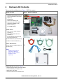
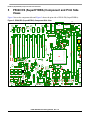
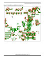
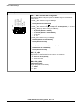
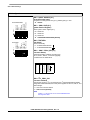
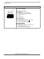
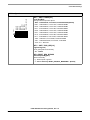
Freescale Semiconductor
Hardware Getting Started Guide
Document Number:
P5040 DS_HGS
Rev. 1.5
P5040 DS (SuperHYDRA)
Contents
This document describes the P5040 DS (SuperHYDRA) and
its related hardware kit. The P5040 DS (SuperHYDRA)
Getting Started procedure explains and verifies basic board
operation in a step-by-step format.
Settings for switches, connectors, jumpers, push buttons, and
LEDs are shown, and there are instructions for connecting
peripheral devices.
The P5040 DS (SuperHYDRA) functions with an integrated
development environment (IDE), such as Freescale’s
CodeWarrior ™; however, instructions for working with the
IDE are beyond the scope of this document.
© Freescale Semiconductor, Inc., 3/2012. All rights reserved.
1. Revisions Table
2
2. Acronyms and Abbreviations
2
3. Related Reading
8
4. Hardware Kit Contents
9
5. P5040 DS (SuperHYDRA) Component and Print
Side Views
10
6. Switch Default Settings
12
7. Connector Default Settings
29
8. Jumper Default Settings
32
9. Push Buttons
33
10. LED Lights
34
11. Working Environment
37
12. HW Getting Started Procedures
37
12.1 Standalone Mode
38
12.2 PC Mid-Tower Mode
40
13. SerDes Options
42
Revisions Table
1
Revisions Table
Table 1. Revisions Table
Date
Rev.
Author
Tech Editor
Description
Dec 2011
1.0
Vladimir Yukht &
Limor Peretz
HWGS Rev. 1.0
Jan 2012
1.1
Vladimir Yukht &
Limor Peretz
HWGS Rev. 1.1
Jan 2012
1.2
Vladimir Yukht &
Limor Peretz
“Programming model” paragraph
removed (See User Guide for details)
March 2012
1.21
Vladimir Yukht &
Limor Peretz
P5021 device setting added
March 2012
1.22
Vladimir Yukht &
Limor Peretz
Photo’s are updated. Ref. clocks
default setting added
May 2012
1.3
Vladimir Yukht &
Limor Peretz
Default SYSCLK for P5040 changed to
100MHz
July 2012
1.4
Vladimir Yukht &
Limor Peretz
Default SYSCLK and PDN option for
P5040 changed to 133MHz & CA+CB
-Common; PL - Independent. P5021 &
P5010 devices setup added
Oct 2012
1.5
Vladimir Yukht &
Limor Peretz
Optional DDR_RST program control
added. FPGA OCM/DCM updated
2
Acronyms and Abbreviations
Table 2.
Usage
Description
ACK
Acknowledge
ADDR
Address
ARCH
Architecture
ATX
Advanced Technology Extended (power supply)
AURORA
Aurora Systems
AUX
Auxiliary
AVDD
Address Bus Voltage
BRDCFG
Board Configuration
BVDD
Local Bus Direct Current Voltage
P5040 DS Hardware Getting Started, Rev. 1.5
2
Freescale Semiconductor
Acronyms and Abbreviations
Table 2.
Usage
Description
CA
Core A
CB
Core B
CC
Core Cluster
CFG
Configuration
chkstpi
Checkstop In
CLK
Clock
CLKIN
Clock Input (interchangeable with SYSCLK)
CLKSPREAD
Clock Spread
CNTL
Control
COP
Common On-Chip Processor
CPU
Central Processing Unit
CSR
Control Status Register
CVDD
Clock Driver Supply Voltage / Bus Control Voltage
CW
CodeWarrior
DBGSEL
FPGA GMSA GMDBG Register Select
DDR
Double Data Rate
DIP
Dual-In-Line Package (switches)
DIR
Direction
DIS
Disable
DRAM
Dynamic Random Access Memory
DS
Development System
EC
Chip HW Specification
ECC
Error Detection and Correction
eDINK
e500 core Demonstrative Interactive Nanokernel
EEPROM
Electrically Erasable Programmable ROM
eLBC
Enhanced Local Bus Controller
EMI
ElectroMagnetic Interference
eMMC
Embedded Multi Media Card
EN
Enabled
ENG
Engineering
EP
End Point
P5040 DS Hardware Getting Started, Rev. 1.5
Freescale Semiconductor
3
Acronyms and Abbreviations
Table 2.
Usage
Description
eSDHC
Enhanced Secure Digital High Capacity Card
esig
Internal/Event Signal p. 35
ETH
Ethernet
EVEDEST
Event Destination
EVESRC
Event Source
evt
event
FBSEL
Feedback Select
FCM
NAND Flash Control Machine
FLASHCS
Flash Chip Select
Fman
Frame Manager
FPGA
Field Programmable Gate Array
FSEL
Frequency Select
GEN
Generate
GETH
Giga Ethernet (GbE)
GPINPUT
General Purpose Input
GPIO
General Purpose In/Out
GVDD
Gate Turn-On Voltage / GPIO Voltage
Host
P3041/P5020
HRESET
Hard Reset
HSTAT
Hydra Status
HW
Hardware
HWGS
Hardware Getting Started
I2C
Inter-Integrated Circuit Multi-Master Serial Computer Bus
ICS307
System Clock Generator
ID
Identification
IDE
Integrated Development Environment
IO
Input/Output
IPL
Initial Program Load
ISOL
Isolated
JTAG
Joint Test Access Group (IEEE® Std. 1149.1™)
LBMAP
Local Bus Map
P5040 DS Hardware Getting Started, Rev. 1.5
4
Freescale Semiconductor
Acronyms and Abbreviations
Table 2.
Usage
Description
LED/LD
Light-emitting Diode
LP
Low Power
LSB
Least Significant Bit
LVDD
P5040 DS (SuperHYDRA) GETH (Low) Voltage
MII
Media Independent Interface
MMC
Multi-media Card
MSB
Most Significant Bit
MUX
Multiplexer
NAND
Flash Memory
NDA
Non-Disclosure Agreement
NG/ng
New Generation; e.g., ngPIXIS
NOR
Flash Memory
NVIDIA
NVIDIA Corporation
OCM
Off-line Configuration Manager (FPGA-embedded)
OCMCSR
OCM Control/Status Register
OCMMSG
OCM Message
OPT
Option
OVDD
Output Voltage
PCIe/PEX
PCIe = PCI Express = PEX
PG
Power Good
PHY
Physical Layer
PIXISOPT
PIXIS Option
PJWP
PROMJet Write Protect
PL
Platform
PLL
Phased Lock Loop
POVDD
Parameter Operating Voltage
ppm
Parts per Million
PROC ISO
Processor Isolated
PROC SEL
Processor Select
PROMJet
Memory Emulator by EmuTec Inc.
PROMJet Flash
Flash by EmuTec Inc.
P5040 DS Hardware Getting Started, Rev. 1.5
Freescale Semiconductor
5
Acronyms and Abbreviations
Table 2.
Usage
Description
PS
Power Supply
PWR
Power
QorIQ
Brand of power architecture based on a Freescale
communications micro controller.
R
Read
RC
Root Complex
RCW
Reset Configuration Word
REF
Reference
REF CLK
Reference Clock (Clock Synthesizer Input Value)
REG
Register
REG CFG
Configuration Register
REQ
Request
RGMII
Reduced General Media Independent Interface
RM
Reference Manual
ROM
Read Only Memory
RSP
Response
RST
Reset
RTC
Real-time Clock
SATA
Serial Advanced Technology Attachment
SCL/SCLK
Serial Clock
SCVER
System Control Version
SD
Secure Digital Card
SDHC
Secure Digital High Capacity
SDREFCLK
SerDes Reference Clock
SEL
Select
SERCLK
SerDes Clock
SerDes (SRDS)
Serializer/Deserializer; e.g., PEX, XAUI, SGMII, SATA, sRIO,
AURORA
SGMII
Serial Gigabit Media Independent Interface
SHDN
Shutdown
SMB
Subminiature Version B Connector
SPD
Speed
P5040 DS Hardware Getting Started, Rev. 1.5
6
Freescale Semiconductor
Acronyms and Abbreviations
Table 2.
Usage
Description
SPI
Serial Peripheral Interface Flash
SPICS
SPI Chip Select
SRAM
Static Random Access Memory
STAT
Status
SVDD
Supply Voltage
SVR
System Version
SW
Switch
SXSLOT
SGMII/XAUI Riser Card Slot
SYSCLK
System Clock
TAP
Telocator Alphanumeric Protocol; e.g., USB TAP or ETH TAP
TESTSEL
Test Select
trig/TRIG_IN/OUT
Trigger In/Out
U
Unassigned
UART
Universal Asynchronous Receiver/Transmitter
uDIMM
Unbuffered Dual In-Line Memory Module Form Factor
USB
Universal Serial Bus
USBCLK
USB Clock
V
Volt
VCTL
VELA Control
VDD
Voltage Drain
VELA
VELA Corporation
VER
Version
VSTAT
VELA Status
W
Write
WDEN
Watchdog Enable
WP
Write Protect
WVAL
Watchdog Value
XAUI
Ten Attachment Unit Interface
XVDD
Phased Lock Loop Voltage
P5040 DS Hardware Getting Started, Rev. 1.5
Freescale Semiconductor
7
Related Reading
3
Related Reading
The documents listed in the below table are available via the Freescale website to those with NDA access.
The website is found at http://www.freescale.com/.
Table 3. Related Reading
Document
Description
CodeWarrior™ Kit Configuration Guide
• Complete HW setup explanation.
• Kit Configuration Guide explains how to set up and use
each SW component in the development kit.
P5040 QorIQ
Integrated Multicore Communication Processor
Family Reference Manual
P5040 RM
P3041 QorIQ
Integrated Multicore Communication Processor
Family Reference Manual
P3041 RM
P5020 QorIQ
Integrated Multicore Communication Processor
Family Reference Manual
P5020 RM
P5040 QorIQ Integrated Processor
Hardware Specifications
P5040EC
P3041 QorIQ Integrated Processor
Hardware Specifications
P3041 EC
P5020/P5010 QorIQ Integrated Processor
Hardware Specifications
P5020 EC
Hydra DS SerDes Support
All P3041/P5020DS SerDes support options.
P5040 DS SerDes Support
All P5040DS SerDes support options.
Intersil ISL6313B Datasheet
Two-Phase Buck PWM Controller with Integrated MOSFET
Drivers for Intel VR11 and AMD Applications
P5040 DS (Super Hydra) HWUG
Super Hydra User Guide
P5040 DS Hardware Getting Started, Rev. 1.5
8
Freescale Semiconductor
Hardware Kit Contents
4
Hardware Kit Contents
This section lists and depicts (see Figure 1) HW kit contents.
Figure 1. HW Kit Contents
HW Kit Inventory
Photo A: Board and External HW
1. P5040 DS (SuperHYDRA) board (1)
with connected DB9 Cross Gender
adapter (1)
1
2. PC Mid-Tower
3. ATX PS 12V 600W (1) and
US/Canada cable & PS adapter
A
2
3
4. CodeWarrior USB TAP (1 kit)
5. DVD/CD: SATA2 (1)
6. HD: 160GB SATA (1)
Photo B: Cables
7. ETH cross-over cable with RJ45
connector (1)
4
8. ETH shielded cable with RJ45
connector (1)
9. RS-232 standard serial cable with
two 9-pin connectors (1)
5
7
10. SATA cable with 7-pin connector (2)
6
8
9
11. USB*A-to-MicroUSB*B cable (1)
Photo C: Miscellaneous
12. Micro USB*A-to-USB*A adapter (1)
B
10
13. Allen key (1)
11
NOTE!
Standalone version does not
include the PC Mid-Tower,
DVD/CD, and HD—marked as
numbers 2, 5, and 6,
respectively.
C
12
13
PRINTED MATTER (not shown in Figure 1):
• P5040 DS (SuperHYDRA) HW Getting Started
• Freescale Warranty Card: 920-75133
• Safety Notice: 926-75254
• Contact Information Sheet: 920-90570-00
P5040 DS Hardware Getting Started, Rev. 1.5
Freescale Semiconductor
9
P5040 DS (SuperHYDRA) Component and Print Side Views
5
P5040 DS (SuperHYDRA) Component and Print Side
Views
Figure 2 shows the component side and Figure 3 shows the print side of P5040 DS (SuperHYDRA).
Figure 2. P5040 DS (SuperHYDRA) Component Side View
POWER
HRST
C5
L1
C13
C
CR1
F2
A
C21
L7
R16
R4
R63 C33 R55
R64
TP4
R8
R7
TP2
L6
R38
C46
C45
R82
R96
R97
C44
R33
R31
R32
R879
R37
1
R54
4
5
8
8
5
C37
R50
F3
4
1
8
5
1
120
120
240
240
CAUTION HOT!
110
230
110
230
R150
R149
R152 C148
100
220
100
220
R160
1
3
6
C182
4
90
80
CAUTION HOT!
90
210
80
200
210
200
C181
1
6
C201
R184
C200
6
10
60
50
5
1
C205
C204
TP161
C206
TP155
4
J31
R182
3
70
C198
70
190
60
180
50
DDR3 DIMM2
170
J30
180
170
DDR3 DIMM1
M_VTT
TP162
VCC_DDRA_IO
TP264
40
40
160
160
GND4
C324
3
30
150
30
20
140
20
J32
36
35
34
33
32
31
30
29
28
27
26
25
24
23
22
21
20
19
18
17
16
15
14
13
12
11
10
9
8
7
6
5
4
3
2
1
140
TP176
R284
R276
TP175
C872
12
2
1
F7
MH7
R295
130
10
130
1
1
1
1
121
121
C248
5
7
C1005
9
6
8
10
7
2
TP250
3
J46
5
4
U65
8
R1018
1
U155
1
U154
1
1
20
21
28
1
R1019
TP253
TP252
R329
C300
4
3
1
2
C982
4
2
C1008
R943
R942
18
C1015
10
36
R947
1
1
2
C978
R912
19
27
28
U135
J41
R911
R936
D37
C971
1
56
48
U156
1
24
U134
A
R948
R838
R839
R1016
12
13
R1017
1
D35
D36
U142
1
TP251
C
1
1
U144
21
20
28
29
U141
1
48
56
49
J47
3
1
R937
U140
1
R315
C277
R313
+
2
+
1
9
R920
U153
3
1
1
2
R927 R914
1
C1060
4
3
4
+
C976
C1022
R983
TP254
49
29
1
2
C1053
R987
R989
10
3
4
3
3
4
+
R994
C
2
1
R961
R982
C226
R235
1
TP247
TP248
TP249
A
C305
C307
1
13
C321
1
12
6
18
9
U152
J43
J35
R320
C327
TP246
13
U63
1
U147
36
1
1
U143
19
24
19
R300
R314
1
Q28
Q30
Q25
R951
18
Q26
C322
C318
R383
C325
R997
R370
R371
R382
MH9
1
J52
1
3
8
2
TRIG OUT TRIG IN
4
J51
1
4
C955
27
R993
R972
D38
C224
1
U64
5
R369
TP245
5
R361
J45
R362
R360
TP243
Flash
FPGA
Prog
C227
GND5
1
1
C1025
R960
28
C1023
C876
29
4
1
1
3
4
4
3
+
1
U39
Q38
Q40
Q36
C235
2
1
R965
L20
2
1
C234
R262
Q35
56
28
TP256
TP255
R328
TP236
TP226
R263
TP235
1
50
C276
1
C295
24
R333
TP227
R327
C290
C294
U60
49
L34
L37
C291
R326
ATX PS 12V2
L36
TP261
1
U51
5
C289
L35
8
4
F8
C287
TP262
R311
R309
R310
R308
U52
C275
1
C299
C274
ATX PS
11
12
13
D18
D29
R319
C293
TP267
J40
C270
24
12
C1004
4
Q29
121
121
2
5
7
9
R923
13
12
11
10
9
11
13
12
3
1
2
3
1
4
6
Q24
8
7
C1026
R272
R271
R274
R281
R280
R282
R270
R273
R269
R275
2
3
1
5
4
8
6
Q34
10
R969
9
12
13
10
11
TP203 GND8
VDD_CA
C1027
R255
R254
R253
R252
R251
R236
R242
R241
R240
R239
R238
R237
3
2
R291
5
1
4
6
C1048
8
7
1
25
48
10
A1
R293
5
1
C253
C271
C268
C267
8
5
1
C244
C236
C252
C1047
5
1
R305
Q39
NAND
Flash
3
R876
C950
R188
150
C215
C218
C231
R223
R224
R225
R226
R227
R228
R229
24
1
R222
4
C266
X1
TP215
TP214
TP242
D32
R842
R187
U24
13
2
R307
NOR
Flash
9
1
J44
R186
TP263
R312
C273
C317
2
EVENT
R358
R357
1
1
R359
SW16
1
A
C
SW15
R185
C221
C222
6
1
R259
R260
C233
R289
C279
C280
TP268
R841
J50
C323
1
TP265
4
R964
C310
SW14
MH8
R204
R205
R200
R201
R202
R203
C951
D31
D5
R356
4
C
C311
R355
R354
R353
6
3
J49
C
1
J48
1
10
U157
R347
D4
J38
1
7 8
A
6
A
3 4 5
A
2
C309
R318
TP224
TP225
TP266
1
1
8
D3
1
C245
C269
C288
J34
1
7
J42
C313
4 5 6
SW8
C312
SW4
COP/
JTAG
C265
C281
R331
16
1
R302
7 8
2
5 6
15
1
2 3 4
3
1
D33
7 8
C316
6
2
3 4 5
U56
TP200
C272
C264
R306
R332
1588 Riser Card
2
ON
D34
1
GND9
2
1
C298
C
8
J36
R301
C314
C315
7
SW11
ON
1
4 5 6
SW7
R261
4
J39
TP209
R303
ON
SW3
C254
C263
R323
U23
R183
C262
C285
6 7 8
3
U48
C255
C250
C251
TP177
1
C249
TP210
TP204
TP218
C286
5
R290
R805
2 3 4
R164
R218
U42
R793
VDD_PL GND7
U44
U41
TP185
C243
TP232
1
C183
U19
L18
L19
FID3
R292
TP186
4
5
5
7 8
FL4
3
R279
2
6
U47
3
1
U46
TP194
C284
3 4 5
TP190
4
5
4
2
TP178
TP191
R288
R324
R330
1
59
8
60
7
1
R256
2
R322
U53
J33
2
TP183
R277
TP222
TP221
TP220
4 5 6
U43
R316
C278
SW10
1
ON
R195
28
FL3
1
L21
L22
R317
SW6
R194
1
25
3
C223
C225
GND6
8
Y3
1
R884
R883
6 7
1
C238
1
ON
SW2
C326
5
R790
C282
C283
4 5
U30
24
MH6
R325
2 3
15
C216
C230
TP231
1
7 8
10
20
11
10
FID4
R232
R230
R233
R234
R250
3
6
TP208
FID5
7
R294
C241
3 4 5
11
U133
R880
TP174
TP258
R231
C242
2
R888
1
U35
C292
1
8
R895
U132
28
C213
14
Y2
U38
C219
7
R890
R891
R882
R881
SW9
1
20
C239
4 5 6
ON
SW5
R210
1
R246
8
U34
C240
7
PROMJET
4 5 6
R216
R217
R221
1
R257
3
R247
1 2
C229
8
R215
R213
R214
11
10
U37
R249
C228
6 7
20
U33
1
10
11
R894
3 4 5
U36
R244
R245
R887
2
ON
SW1
2 3
9
AT
AR
AP
AN
AM
AL
AK
AJ
AG AH
AF
AE
AD
AC
AB
AA
Y
W
V
U
T
R
P
N
M
L
K
J
H
G
F
E
D
C
B
A
C605
C202
TP259
R197
R258
R243
SW13
1
20
C961
ON
SW12
R219
10
U32
R212
R248
C232
1
11
R211
1
C960
ON
R208
R209
1
14
MH5
U31
R206
R207
7
U58
R220
5
R199
R198
8
8
C308
4
R868
U55
7
8
U57
TP260
TP257
R193
R196
R869
R867
8
5
1
TP173
C217
R192
TP165
U29
10
14
U54
4
1
C173
2
3
C197
1
25
C214
TP170
TP167
TP164
c
d
1
24
C212
TP166
TP163
1
1
21
2
U28
TP169
1
TP172
2
TP168
e
1
1
R337
R336
R341
R342
2 3
4
R181
10
TP171
c
d
10
3
4
e
c
d
4
C220
1
1
C144
R158
20
U26
11
14
C246
e
1
5
b
C211
11
a
f
g
CAUTION HOT!
ON
R49
J15
F5
C87
C115
C143
J27
5
1
16
U27
R870
R866
R871
b
g
C296
c
d
DS2
a
f
C210
20
b
g
TP233
e
R191
D14
11
a
f
C209
D13
b
g
1
a
f
R153
R172
6
U22
15
1
15
R190
DS1
20
R2-191
R1-191
R189
R865
CPU TYPE/POWER MODE
D12
GND2
TP157
TP158
11
TP156
28
25
A82
B82
A82
B82
A82
B82
A82
B82
C208
A82
B82
A82
B82
A82
B82
D10
ON
U17
R173
10
TP154
1
10
U25
24
C207
2 3
J16
SYSCLK
C674
1
C36
R27
C31
1
C65
C86
C111
C113
C55
C57
TP147
TP145
TP153
TP150
11
14
15
C203
ON
6
Q32
13
J28
1
C606
C199
C
2 3
8
10
11
12
1
C180
10
D9
D11
MH4
C114
TP138
TP148
TP146
TP159
D30
D8
R43
R148
TP139
TP137
R169
R179
RTCCLK
D20
1
C957
4
C60
C56
R145
R156
C178
5
6
C192
R167
R171
4
U18
1
L17
R163
5
8
R159
11
D28
D7
L5
R42
R41
R83
C58
VDD_CB
TP136
C179
20
D27
D6
R40
U131
190
41
31
J29
40
TP160
30
D26
R168
FL2
TP140
AURORA
50
D24
D25
ON
R39
J4
1
R17
3
C193
R170
R165
R166
FL1
R175
69
R1004
28
61
70
1
25
C468
51
C195
D23
A
TP39
1
2
C88
GND3
U20
R1005
24
60
C194
C172
L16
R1006
U161
SLOT 7
C185
10
15
J26
J25
C184
SLOT 6
SLOT 5
J24
J23
SLOT 4
J22
SLOT 3
SLOT 2
J21
SLOT 1
J20
28
11
25
14
C176
D21
R1008
R1009
R1007
1
C175
D19
19
R151
Y1
C170
10
U162
24
D22
C43
C
TP5
27
18
U12
R81
L13
C171
11
14
15
C169
C177
4
1
C168
R154
D17
D16
A CR2
U3
R878
1
U11
C164
1
C167
C163
10
C166
R51
TP111
28
36
10
FID1
C11
R9
C162
C160
TP149
C165
C42
A
D1
TP3
F1
L12
J19
L15
C159
C158
C2
D15
R146
R144
C141
C157
C85
1
C142
C140
C155
C156
C152
R174
C137
C154
C151
R178
C136
C134
C153
C150
R176
C135
C973
C149
R177
C972
C133
J17
1
TP144
C132
C131
JP1
C128
C129
C61
C59
R95
R134
TP142
C130
C82
R123
C110
C97
TP110
TP109
R52
TP107
28
27
19
L9
1
9
R53
C66
C84
C81
C109
C96
C80
R122
Q1
C108
10
C53
24
15
14
25
11
C52
1
28
C78
U10
L8
C62
C64
C83
TP152
C138
C139
R116
R113
C76
C32
TP108
36
1
R36
R35
10
C41
J11
TP81
R34
9
R48
C63
C54
C79
C107
R141
R94
C105
C126
C127
R140
R93
25
C106
C124
R75
28
24
TP141
R136
1
18
5
C112
C125
R139
1
U160
15
R135
C122
C123
R138
14
TP143
C117
C28
R85
R29
U6
F4
R157
C120
C121
11
25
R180
C118
C119
R137
R115
10
28
24
TP151
C95
R128
R126
U159
15
R147
R109
C74
R125
C49
B1
R111
C77
R106
R112
C75
R107
1
10
C103
C92
C94
11
14
C102
C72
C93
U15
C104
C116
U9
1
U14
C
C7
R15
R13
R14
C20
U7
R79
R80
C39
R28
5
6
28
R56
C34
R73
C50
R114
R130
R102
A1
+
A1
B1
+
+
C73
C71
C70
A1
B1
A1
B1
+
+
B1
A1
R105
R103
C69
R127
R110
R108
R129
R124
U8
15
3
C379
1
C147
C38
A1
C48
+
+
B1
+
+
C47
B1
A1
C90
C91
U5
4
1
R74
C51
R104
R100
C67
C89
R99
J12
2
1
SATA2
C378
1
C27
14
C365
R101
C68
R26
1
15
1
U4
R30
R62
J14
1
C366
R98
9
R12
R11
8
R61
J13
SATA1
1
C25
16
C364
C363
1
R78
TP106
TP104
12
13
5
C145
TP105
TP102
7
C24
R25
R24
1
R5 C10
R2
R3
R1
T1
L4
5
C146
TP99
TP98
T6
L3
R44
R45
R46
TP80
C19
R47
TP79
TP77
6
R77
TP78
C367
TP75
TP103
1
C17
C35
TP101
T9
T5
C16
16
13
C40
TP73
GETH2
B1
C18
6
1
C15
TP38
SD Card
1
TP71
TP100
C14
TP36
TP37
C26
TP76
TP74
TP72
J10
C368
TP35
R76
TP95
TP94
TP34
TP33
TP68
TP70
TP96
TP32
40
39
TP31
TP69
TP97
TP92
TP261
TP30
TP66
TP63
TP61
40
A
TP67
TP60 TP65
TP59
TP93
TP269
J9
R10
39
40
TP58
TP57
TP54
TP29
PCI SLOT EXT.
TP56
TP55
C23
TP28
TP64
RS-232
B5
5
C6
TP1
B6
R57
R58
R59
D2
TP270
TP91
TP89
C22
TP275
TP27
1
TP280
TP62
PCI SLOT EXT.
TP282
TP277
TP274
TP25
TP23
C12
3
GETH1
& USB1
2
TP273
TP272
PCI SLOT EXT.
TP276
TP278
TP52
39
40
39
TP281
TP51
TP26
TP24
2
1
1
2
TP87
TP85
TP50
TP49
TP90
TP88
TP22
1
TP48
TP19
TP53
2
TP46
TP21
5
TP284
J5
R60
4
6
TP83
40
39
R21
R22
R23
TP47
TP45
TP44
J8
TP20
1
TP289
TP286
PCI SLOT EXT.
TP43
TP86
TP84
TP279
TP18
1
R19
TP41
TP82
TP283
TP285
TP16
U2
J53
TP287
TP288
TP17
TP15
PCI SLOT EXT.
R18
TP40
C30
J7
TP14
TP12
TP11
TP42
2
R20
2
TP10
PCI SLOT EXT.
TP8
TP7
1
40
J6
TP9
TP6
GND1
TP13
39
FID2
P1
A1
B9
1
R6
J2
A4
U1
C9
C
MH2
1
MH3
L2
C8
MH1
C29
C3
J1
C1
C4
C174
USB2
J3
MH10
FID6
P5040 DS Hardware Getting Started, Rev. 1.5
10
Freescale Semiconductor
P5040 DS (SuperHYDRA) Component and Print Side Views
Figure 3. P5040 DS (SuperHYDRA) Print Side View
R385 R384
R516
C447
C448
R858
R846
1
C329
R386
R432
C348
C347
R404
C336
C346
C369
C370
C371
C372
C374
C373
C677
C611
39
C5
C5
70
RN16
C974
C981
C975
C993
C995
C996
R931
R958
R917
C1040
10
C994
C989
C992
C987
C990
C991
C1006
C1012
C998
C983
C986
R926
R922
R910
R1012
R939
C1003
R918
R935
C977
R1013
R944
R934
R921
C980
R928
C1035
C1044
6
R996
C947
RT1
C1002 C1010
5
6
1
10
R945
R915
C999
C1011
C1013
RN15
C1007
C1080
C1081
5
C1033
C1058
R995
C946
R1014
R985
R929
U139
C985
C1052
R773
U137
C1051
R938
C856
C952
R843
C1034
C1037
C1036
R956
R930
U138
U149
C1054
R991
1
C1001
R946
C1014
C953
R973
R966
C895
Q31
R924
R940
R856
C1043
C1056
C1031
R925
C997
R933
C948
R950
C988
C1016
MP5
R949
GND
FID9
C954
R855
R845
R844
R848
R847
C615
R278
B
U136
R975
C1061
C949
R979
C1049
R992
C1059
R853
R854
R852
1
R857 1 U127
R851 R840
U158
1
R916
U148
C1050
R968
R748
C944
R638
R544
R541 C483
18
C5
C5
89
C7
73
C81
1
F
D
R941
C1021
C877
C331
R406
R405
R394
R393
R451
R450
R435
C451
C454
C452
C455
C453
C456
R526
L31
R527
R578
C52
5
51
C5
C5
92
19
C8
C1032
C1041
C1017
C1018
C1019
C1039
C1038
C892
R768
R796
R802
R803
C920
R801
R812
C927
C8
08
R896
R713
R708
R707
R712
R715
C919
R809
R765
C890
R766
R267
H
1
RN18
K
1
1
R264 C891
C938
Q27
1
R1015
R990
R980
R967
C1030
C893
R769
R767
C612
C676
1
R810
R807
R806
R811
R651
R523
R521
R558
R557
R556
R555
R539
R538
R537
R536
R535
C8
15
C798
R660
C737
R794
Q37
R957
1
RT2
U40
4
5
R640
R641
R642
R639
R791
C1085
RN11
A
M
C678
C899
C1084
RN12
C900
C1055
BT1
E
C
T
P
C608
R788
C1046
R984
R1010
1
C1042
R970
R986
C854
C945
R971
R977
R988
R1011
J
G
V
C557
C609
R786
R787
R283
C898 C897
1
U118
1
3
R822
R821
10
FID10
R704
U151
R804
C921
10
C939
L
Y
1
L33
R335
U119
N
C613
R904
R909
C926
AA
1
R548
2
R542
22
U120
R726 R727
C836
C834
R286
C888
R974
1
C887
R976
R963
1
10
U150
C1020
U107
R728 3
1
R800 R799
C1028
R703
AB
R
C614
C610
R687 R680
U108
C1057
1
R902
C835
C838
C874
R981
6
Q41
1
R792
L32
C922
C928
U
R654
R655
R903
R908
R905
C851
R959
5
C760
R669
C1024
6
R813
AA
R645 W
C528
C558
C559
C896
C1082
C1083
5
1
R646
C625
AB
C560
C508
C529
C530
R647
48
C1029
10
C759
C764
C839
C873
C1045
1
R818
U115
R817
1
10
C909
C910
C915
6
5
1
U50
R797
6
10
U121
R545
C929
6
RN8
1
R547
5
RN9
RN7
5
R819
R546
6
5
C923
R304
R860
R634
R900
R657
R763
U116
1
R814
C629
1
10
R815
C763
C768
R287
R285
1
C767
C772
R705
U117
RN4
10
R577
RN5
1
R562
1
1
R656
R795
10
RN6
1
6
AD
AC
C901
R268
1 A
A1
B 21
GND
C561
R620
R621
R633
R632
AF
C493
C842
35
36
R808
10
5
C847
MP4
RN1
6
C731
5
R266
C771
C776
C812
25
1
C635
C639
1
6
R265
C780
C843
U109
C889
5
C912
C930 R321
5
C911
C959
8
1
1
R889
R886
R885
C958
1
C964
R892 C965
10
6
C875
C644
R665
R709
24
C624
C679
R643
R729
R764
R762
U111
4
1
R734
10
RN2
10
R736
R738
RN3
1
5
C881
1
6
R710
U110
C902
C963
C962
5
C878
6
R893
6
5
R714
C868
C634
C617
C845
R637
R711
C857
R716
R730
R731
R732
R733
R735
R737
R739
R740
C894
C882
C885
R770
C883
R753
R754
R755
R749
R750
R751
R752
C884
R836
R741
R742
R743
R744
C879
C880
R745
C858
C862
C869
5
1
10
C870
C871
C886
C859
C861
C623
C510
C509
C532
AH
AE
C572
C633
C709
C785
R670
R695
R696
R697
R698
R699
R700
6
10
1
5
C865
R746
R747
U126
RN13
6
C864
1
R835
C860
R717
R718
R719
R720
C866
R722
C863
1
5
1
RN17
U124 R721
C574
C577
C651
C844
AP
AM
AK
C478
C485
C494
C511
C531
C512
AG
C580
C783
C818
C846
C852
R702
C867
C940
AL
C486
C495
C513
AT
C479
C487
C496
AN
C571
C790
C820
C821
R701
C853
U123
R823
RN10
C792
C822
C823
C488
R581
AJ
R626
C588
C590
C784
C480
C481
R571
R601
C591
C652
C795
U145
4
R600
R603
C583
C788
R953
R9521
R899
R604
C666
1
1
U98
R582
C547
C789
U89
C450
C497
R572
C707
C849
U104
5
C725
C791
11
R540 C482
C489
C491
C490
8
1
U95
AR
C549
C596
C671
C726
C794
10
14
8
R574
C524
C724
C728
C793
C848
1
1
U125
1
15
U106
U122
C932
C941
24
C850
1
1
R875
R874
1
C673
C729
C796
5
U96
C500 C498
C669
C730 C727
C732
1
C471
R573
C595
C734
R658
R659
R873
1
1
U105
C825
Q23
R649
R650
R872
1
Q22
R663
R756
Q21
R648
C733
U102
C797
25 28
C826
Q20
R671
R760
U103
C824
R757
C827
R758
4
6
R724
R723
3
1
R759
15 10
14 11
R561
1
R725
C735
25 28
1
24
C736
R532
C520
C548
C598
C602
C670
MP3
8
C501
C523
C597
C600
C601
C672
GND
4
R560
C503
C505
C594
C599
C604
C607
C675
R550
C603
R631
R630
R553
1
10
R552
C556
GND
Q33
R652
R622
R635
1
28
R644
R653
C8
2
33
38
2
16
C5
C7
C6
C56
3
00
99
0
39
34
C8
C7
C7
C5
4
4
C68
63
64
41
C51
C5
C5
R636
81
1
5
5
29
42
18
C7
C6
C8
C7
C80
40
C6
C53
2
6
9
36
65
C7
C5
C68
C5
C61
2
6
5
7
03
44
43
C8
C7
C56
C80
C51
8
8
0
C7
30
37
9
C8
C53
C62
6
5
C5
3
04
1
67
C8
C74
R672
C684
C68
C74
C5
C62
10
C499
16
C568
C622
C5
R673
11
9
0
05
31
C569
C685
C748
C686
C747
C8
C74
C8
C54
R906 12
C969
R674
C626
C687
C688
C751
C750
R583
13
7
R675
06
17
C627
C628
C689
C690
C752
C753
R901
C8
C80
C5
R584
14 R676
41
32 R664
C573
C630
C631
C691
C692
C755
C754
C5
15
C502
C8
2
C575
C632
C693
C694
C757
C 756
C833
16 R677
R898
C54
R678
09
C576
C636
C695
C696
C 758
19
R627
R602
C8
C5
17
R679
C637
C638
C697
C578
C698
C761
18
R575
R681
43
C579
C699
C700
C762
C640
C641
C5
19
R682
C521
C581
C701
C702
C642
C643
C765
R907
R683
20
C970
C645
C704
C837
C582
C646
C703
C 766
21 22
R576
R684
85
R585
R605
R849
C705
C769
C584
C647
C648
C706
C5
R859
R685
C545
C586
C649
C650
C708
C770
44
R686
C810
C5
R586
C587
C653
C710
C711
C654
R688
23
C546
R587
C712
C775
24
C655
C656
C657
C713
C 774
R706
R666
R689
25
C658
C659
C660
C714
C715
C777
C778
R690
R667
26
C504
R662
C661
C716
C717
C662
C663
C779
R606
R661
27
R668
C718
C719
C664
C665
C781
C782
R691
R588
R1000
28
C968
C814
R694 1
C506
R628
C840
86
29
C813
C720
R692
C593
C7
C855
30
C787
R629
C721
R693
C817
31
C667
C841
52
26
C722
C723
C5
C5
32
C816
33
34
11
15
R530
9
R559
C550
3
C55
14
R610
U101
5
R607
55
C5
28
24
R615
U114
R334
R608
R609
25
U92
16
R534 R533
54
C5
R616
U97
1
1
8
C522
27
R789
R771
1
R618
R761
R619
U100
R1003
C507
C5
R597
R598
R617
R778
R579
R590
R591
R592
R593
R594
R611
R612
R613
R614
R595
R589
R779
1
R596
U99
C966
R780
C967
R781
C398
C432
MP1
C433
C465
R524 U9
R525
C466
1
R580
1
R782
1
R480
R481
C397
C445
R543
4
R1001
R567 R1002
R569
U45
X2
R549
R897
R554
R565
R564
R566
R56
R783
4
R551
C1070
R784
5
R528
R529
C1072
C1073
U80
C353
1
1
R785
4
C459
C460
C461
U90
8
R776
R775
R772
1
R514
5
C1071
1
R774
C376
R483
Y4
4
C1075
C1076
4
Q4
U146
C399
R506
C470
C469
L30
1
C1074
5
R433
R434
U81
Q5
C444
R520
C1077
C330
1
Q3
C375
C400
R519
MP2
GND
8
1
8
R515
1
C449
R517
Q6
1
Q2
C332
C337
C430
U86
R507
U88
Q7
A
B
C
D
E
F
G
H
J
K
L
M
N
P
R
T
U
V
FID7
C328
5
4
C431
R484
C439
C377
R485
C1063
C1065
R999
C1069
C1064
C1062
C382
R998
C1066
C1067
C383
C381
C401
C1068
C403
C402
C405
C385
C407
C406
R498
C404
C408
C415
C388
C417
C391
C424 C393
C413
C410
R499
R503
R513
C426 C425
C429 C428
R505
R497
5
28
1
1
5
25
U85
10
8
14
11
L26
1
8
24
15
C384
3
4
R511
C440
C441
C386
4
C414
C418
C409
C411
1
R512
C387
C412
8
R500
C416
5
C389
C360
1
C442
C443
C420
C359
1
2
3
4
5
6
87
9
10
11
12
13
14
15
16
17
18
R502
C422
C419
C421
R501
+
C390
+
C392
C423
+
C427
+
C394
C395
R504
+
C396
1
R457
R458
R477
R479
R478
C354
C357
C358 C356
C355 R476
R391
R392
R408
R409
R410
R407
1
4
C333 R390
R954
R955
R400
C352 U84 U82
C362
U83
C350
U70
R624
R599
R625
R623
R461
R463
9
R456
R455
R454
R453
R452
R412
R411
R440
R459
R398
C334 R397 U71
C338
1
R436
1
6
4
R464
8
U78
16
R460
C1079
R462
C1078
R919 C979
C984
C1000
R466
R467
1
R465
U72
1
R469
R416
C339
1
R471
R443
R468
R401
R414
1
R415
U73
R413
C340
R442
R438 R439
R445
R419
C341
R441
1
1
C349
U79
8
R421
R422 R420
R444
C342
C361
R447
R470
R403
U74 R418
U75
1
16
R417
9
C351
R472
R473
R424
R425 R423
C344
1
R474
C343
U76
1
R446
R449
R475
U69
R427
R426
R430
R429
1
R428
U77
R448
C345
R437
R402
R431
FID8
1
U68
R399
R396
R395
R387
C1009
R389
R388
C335
L27
U67
L28
L29
P5040 DS Hardware Getting Started, Rev. 1.5
Freescale Semiconductor
11
Switch Default Settings
6
Switch Default Settings
Default DIP-switch positions establish the P5040 DS (SuperHYDRA) mode; see Table 5.
NOTE!
Ensure DIP-switches are set according to default values.
Table 4. P5040 DS (SuperHYDRA) Default Configurations
Mode
Term
Default Value
Unit
AVDD_CC1, AVDD_CC2,
AVDD_PLAT, AVDD_DDR
PLL’s Supply Voltages
(Core, Platform and DDR)
1.05 for P3041/P5020
1.0 for P5040
V
AVDD_SRDS1, AVDD_SRDS2,
AVDD_SRDS3
SERDES PLL’s Supply Voltages
(Filtered from SVDD)
1.05 for P3041/P5020
1.0 for P5040
V
BVDD Voltage
eLBC Block Supply Voltage
3.3 only
V
Core Clock
Depends on RCW
2260 (P5040) /
2000 (P5020/P3041)
MHz
CVDD Voltage
SPI & SDHC Blocks Supply Voltage
3.3
V
DDR CLK
Depends on RCW
800 (P5040) /
666 (P5020/P3041)
MHz
Fman CLK
Depends on RCW
600
MHz
GVDD Voltage
DDR DRAM I/O Supply Voltage
1.5
V
LVDD Voltage
Ethernet EMI1, 1588, GPIO Voltage
2.5
V
DUART, I2C, DMA, MPIC, GPIO,
OVDD Voltage
system control and power management, clocking, debug, I/O voltage
select, and JTAG I/O voltage
3.3
V
Platform Clock
Depends on RCW
800
MHz
POVDD Voltage
Fuse programming override supply
Voltage
“0”- Default
1.0/1.5
V
RTC CLK
Real-time Clock
~50
KHz
SerDes REF CLK1
SerDes Reference Clock 1
100
MHz
SerDes REF CLK2
SerDes Reference Clock 2
125
MHz
SerDes REF CLK3
SerDes Reference Clock 3
125
MHz
SerDes REF CLK4
SerDes Reference Clock 4
125 (P5040 only)
MHz
SVDD Voltage
Core power supply for SerDes
transceivers Voltage
1.05 for P3041/P5020
1.0 for P5040
V
SYSCLK (Synthesizer REF CLK)
System Clock
133.333 (P5040/
P5020)/
83.333 (P3041)
MHz
USB_VDD_1P0
USB PHY PLL supply Voltage
1.0
V
P5040 DS Hardware Getting Started, Rev. 1.5
12
Freescale Semiconductor
Switch Default Settings
Table 4. P5040 DS (SuperHYDRA) Default Configurations
Mode
Term
Default Value
Unit
3.3
V
USB_VDD_3P3
USB PHY Transceiver supply Voltage
VDD_CA Voltage
Cores Group A supply voltage
(not used for P3041)
1.1 for P5020/P5040
V
VDD_CB Voltage
Cores Group B supply voltage
(not used for P3041)
1.1 for P5020/P5040
V
VDD_LP Voltage
Low Power Security Monitor Supply
1.0
V
VDD_PL for P5020/P5040
VDD_PL_CA_CB for P3041 Voltage
Platform/Combined Supply Voltage
1.05 for P5020/P3041
1.0 for P5040
V
XVDD Voltage
Pad power supply for SerDes
transceivers Voltage
1.8
V
P5040 DS Hardware Getting Started, Rev. 1.5
Freescale Semiconductor
13
Switch Default Settings
Table 5 provides schematic drawings and related switch descriptions.
Table 5. SW Configurations
RCW_SRC0
RCW_SRC1
RCW_SRC2
RCW_SRC3
RCW_SRC4
DRAM_TYPE
RSP_DIS
eLBC_ECC
SW1.1 – SW1.5: RCW_SRC[0:4]
(RCW Configuration Source)
Defines RCW configuration sources [0:4] as per P3041/P5020 RM.
1
2
3
4
5
6
7
8
ON ’1’
SW1 Configuration
(Default)
Defines RCW configuration sources [0:4] as per P5040 RM.
Here should be the Table for P5040
P5040 DS Hardware Getting Started, Rev. 1.5
14
Freescale Semiconductor
Switch Default Settings
SW1.6: DRAM_TYPE
(DDR RAM Type)
Defines POR DRAM type (DDR3/DDR3L).
• ‘0’ - 1.5V DDR3 technology [Default]
• ’1’ - 1.35V DDR3L technology
SW1.7: RSP_DIS
(Response Disable)
Defines functionality.
• ‘0’ - RESET pauses at RCW
• ’1’ - Continued Boot [Default]
SW1.8: eLBC_ECC
(Enhanced Local Bus Controller & Error Detection and Correction)
Controls FCM ECC functionality.
• ‘0’ - Disabled NAND Flash ECC [Default]
• ’1’ - Enabled NAND Flash ECC
P5040 DS Hardware Getting Started, Rev. 1.5
Freescale Semiconductor
15
Switch Default Settings
SW2 Configuration
LANE_23_SEL
LANE_45_SEL
LANE_67_SEL0
LANE_67_SEL1
LANE_8_SEL
LANE_1617_SEL
EP_nRC
ENG_USE3
1
2
3
4
5
6
7
8
ON ’1’
SW2.1 – SW2.6: SerDes MUX Configuration
Controls SerDes MUX routing; see Hydra DS SERDES Support and P5040 DS
Serdes Support.
• LANE_23_SEL: Selects routing of LANES[2:3]:
‘0’ - SLOT4 [Default for P3041/P5020]
‘1’ - SLOT7 [Default for P5040]
• LANE_45_SEL: Selects routing of LANES[4:5] ‘0’ - SLOT6 [Default], ‘1’ - SLOT7
• LANE_67_SEL[0:1]: Selects routing of LANES[6:7]
– ‘00’ - SLOT5 [Default for P5040]
– ‘10’ - SLOT6 [Default for P3041/P5020]
– ‘01’ - SLOT7
– ‘11’ - NA
• LANE_8_SEL: Selects routing of LANE[8]:
’0’ - AURORA [Default for P3041/P5020]
‘1’ - SLOT3 [Default for P5040]
• LANE_1617_SEL: Selects routing of LANES[16:17]:
‘0’ - SATA [Default for P3041/P5020]
‘1’ - SLOT1 [Default for P5040]
SW2.7: EP_nRC
(End Point_nRoot Complex)
Controls SLOT7—determines its use as a PEX RC or a PEX EP.
• ‘0’ - SLOT7 as an RC [Default]
• ’1’ - SLOT7 as an EP
SW2.8: ENG_USE3
(Engineering Use3)
[Future option] Defines functionality.
• ‘1’ - Default
• ’0’ - Spare
P5040 DS Hardware Getting Started, Rev. 1.5
16
Freescale Semiconductor
Switch Default Settings
SW3 Configuration
SW3.1: SD1_CLKSPREAD
(SerDes Clock Spread)
SD1_CLKSPREAD
UART2_nUART4
UART2_UART4_SHDN
UART3_nUART1
XVDD_SEL
SYSCLK0
SYSCLK1
SYSCLK2
SD1_CLKSPREAD
UART2_nUART4
UART2_UART4_SHDN
UART3_nUART1
XVDD_SEL
SYSCLK0
SYSCLK1
SYSCLK2
1
2
3
4
5
6
7
8
ON ’1’
For P5020:
1
2
3
4
5
6
7
8
SD1_CLKSPREAD
UART2_nUART4
UART2_UART4_SHDN
UART3_nUART1
XVDD_SEL
SYSCLK0
SYSCLK1
SYSCLK2
For P5040:
ON ’1’
Controls SERDES Bank1 clock spread spectrum modulation—determines if enabled
or disabled.
• ‘0’ - SD1_CLKSPREAD disabled [Default]
• ’1’ - Enabled SD1_CLKSPREAD
NOTE!
To use SERDES Bank1 spread spectrum modulation oscillator Y2 and
R216 & R217 should be assembled while R213 & R214 - are
disassembled.
SW3.2: UART2_nUART4
(Universal Asynchronous Receiver/Transmitter)
1
2
3
4
5
6
7
8
ON ’1’
For P3041:
• ’1’ - P3041/P5020/P5040 UART2 connected to RS-232 DB9 TOP [Default]
• ‘0’ - P3041/P5020/P5040 UART4 connected to RS-232 DB9 TOP
SW3.3: UART2_UART4_SHDN
(UART_Shutdown)
• ‘0’ - Active UART2/UART4 connected to RS-232 DB9 TOP [Default]
• ’1’ - UART2/UART4 in shutdown mode
SW3.4: UART3_nUART1
(Universal Asynchronous Receiver/Transmitter)
Controls P3041/P5020/P5040 UART3/UART1 Flow Control—determines if
connected to RS-232 DB9 BOTTOM; see SW5.7 – SW5.8 description.
• ‘0’ - P3041/P5020/P5040 UART1 Flow Control (RTS, CTS) connected to
RS-232 DB9 BOTTOM [Default]
• ’1’ - P3041/P5020/P5040 UART3 connected to RS-232 DB9 BOTTOM.
SW3.5: XVDD_SEL
(Select XVDD Voltage)
Controls XVDD voltage.
• ‘0’ - XVDD = 1.8V [Default]
• ‘1’ - XVDD = 1.5V
SW3.6 – SW3.8: SYSCLK[0:2]
(System Clock Select)
Selects SYSCLK[0:2] speed as listed below:
• ‘000’ - 66.666 MHz
• ‘001’ - 83.333 MHz [Default for P3041]
• ‘010’ - 100 MHz
• ‘100’ - 133.333MHz [Default for P5040]
• ‘011’ - 125 MHz
• ‘100’ - 133.333 MHz [Default for P5020]
• ‘101’ - 150 MHz
• ‘110’ - 160 MHz
• ‘111’ - 166.666 MHz
P5040 DS Hardware Getting Started, Rev. 1.5
Freescale Semiconductor
17
Switch Default Settings
SW4 Configuration
SW4.1– SW4.2: GPINPUT[0:1]
(General Purpose Input)
GPINPUT0
GPINPUT1
SVR0
SVR1
TESTSELb
PROC_SEL0
PROC_SEL1
I2C1_PROC_ISO
GPINPUT0
GPINPUT1
SVR0
SVR1
TESTSELb
PROC_SEL0
PROC_SEL1
I2C1_PROC_ISO
1
2
3
4
5
6
7
8
ON ’1’
For P3041/P5020:
SW4.3 – SW4.4: SVR [0:1]
(System Version Register)
Defines system version register [0:1].
• ‘00’ - Reserved
• ‘01’ - Reserved
• ‘10’ - Reserved
• ‘11’ - P5040/P3041/P5020/P4080 [Default]
SW4.5: TESTSELb
(Test Select)
Defines functionality.
• ‘0’ - for P3041/P5021/P5010
• ’1’ - for P5040/P5020/P4080
SW4.6 – SW4.7: PROC_SEL[0:1]
(Processor Select)
1
2
3
4
5
6
7
8
ON ’1’
For P5040:
Overwrites PLL settings when CFG_PLL_CONFIG_SEL_B = 1'b0.
• ‘11’ - Default
Combined with SW11.5 defines processor type:
SW11.5, SW4.7 ,SW4.6, = Processor type[2:0].
For detailes see the Table below.
SW11.5 SW4.7 SW4.6 Processor Type
P4080
0
0
0
P3041
0
0
1
P5020
0
1
0
P2040
0
1
1
P5040
1
0
0
P5010
1
0
1
P5021
1
1
0
Reserved
1
1
1
SW4.8: I2C1_PROC_ISO
(Processor Isolated)
Controls CPU access to I2C1 connected devices: I2C RCW EEPROM, SYSTEM
Configuration DATA EEPROM, DC-to-DC power supplies for CPU CA, CB, PL, and
GVDD voltages.
• 0 - CPU cannot access devices
• 1 - CPU accesses [Default]
NOTE!
If SW8.1 = ‘1’ then the CPU can access the EEPROM FPGA
ExConfiguration Data.
P5040 DS Hardware Getting Started, Rev. 1.5
18
Freescale Semiconductor
Switch Default Settings
SDREFCLK1_FSEL0
SDREFCLK1_FSEL1
SDREFCLK2_FSEL0
SDREFCLK2_FSEL1
SDREFCLK3_FSEL0
SDREFCLK3_FSEL1
UART1_3_SEL0
UART1_3_SEL1
ON ’1’
SW5 Configuration
SW5.1 – SW5.2: SDREFCLK1_FSEL[0:1]
(SerDes Reference Clock Bank1 Frequency Select)
Selects SerDes reference clock for bank1[0:1].
• ‘00’ -100 MHz [Default]
• ‘01’ - 125 MHz
• ‘10’ - 156.25 MHz
• ‘11’ - 212.5 MHz; unsupported by P3041/P5020/P5040
1
2
3
4
5
6
7
8
SW5.3 – SW5.4: SDREFCLK2_FSEL[0:1]
(SerDes Reference Clock Bank2 Frequency Select)
Selects SerDes reference clock for bank2[0:1].
• ‘00’ - 100 MHz
• ‘01’ - 125 MHz [Default]
• ‘10’ - 156.25 MHz
• ‘11’ - 212.5 MHz; unsupported by P3041/P5020/P5040
SW5.5 – SW5.6: SDREFCLK3_FSEL[0:1]
(SerDes Reference Clock Bank3 Frequency Select)
Selects SERDES Reference Clock for Bank3[0:1].
• ‘00’ - 100 MHz
• ‘01’ - 125 MHz [Default]
• ‘10’ - 156.25 MHz
• ‘11’ - 212.5 MHz; unsupported by P3041/P5020/P5040
SW5.7 – SW5.8: UART1_3_SEL[0:1]
(UART Connection Select)
Controls UART1 and UART3 connectivity options[0:1].
• ‘00’ - UART1 is connected to RS-232 DB9 BOTTOM; Selects UART1 with flow
control if SW3.4: UART3_nUART1=’0’. [Default]
– Selects UART1 without flow control if SW3.4: UART3_nUART1=’1’.
• ‘01’ - UART3 or Reserved
– Connects UART3 to RS-232 DB9 BOTTOM if SW3.4: UART3_nUART1=’1’
– Reserved if SW3.4: UART3_nUART1=’0’.
• ‘10’ - Connects FPGA to RS-232 DB9 BOTTOM; the UART processor is not used.
• ‘11’ - Reserved
P5040 DS Hardware Getting Started, Rev. 1.5
Freescale Semiconductor
19
Switch Default Settings
SW6 Configuration
RESERVED
RESERVED
RESERVED
RESERVED
VDD_CB0
VDD_CB1
VDD_CB_EN
POVDD_PWR_EN
1
2
3
4
5
6
7
8
ON ’1’
SW6.1– SW6.4: RESERVED
SW6.5 – SW6.6: VDD_CB[0:1]
(Core B Voltage)
[Optional] Defines additional core B voltage[0:1].
• ‘00’ - HW defined by switch SW10[3:4] [Default]
• ‘01’ - Reserved (1.00V)
• ‘10’ - 1.05V
• ‘11’ - Reserved (1.15V)
SW6.7: VDD_CB_EN
(Core B Voltage Enabled)
Controls Core B voltage—determines if enabled or disabled.
• ‘0’ - Disabled core B voltage [for P3041]
• ‘1’ - Enabled core B voltage [for P5020/P5040]
SW6.8: POVDD_PWR_EN
(POVDD Voltage Enabled)
Controls POVDD power—determines if enabled or disabled.
• ‘0’ - Disabled POVDD power supply
• ‘1’ - Enabled POVDD power supply [Default]
P5040 DS Hardware Getting Started, Rev. 1.5
20
Freescale Semiconductor
Switch Default Settings
LBMAP0
LBMAP1
LBMAP2
LBMAP3
ENG_USE0
ENG_USE1
ENG_USE2
RESET_REQ_BYPASS
1
2
3
4
5
6
7
8
ON ’1’
SW7 Configuration
SW7.1 – SW7.4: LBMAP[0:3]
(Local Bus Map)
Controls local bus chip select options.
• ‘0000’ - LCS0=NOR #0, LCS1=PJET, LCS2/4/5/6=NAND [Default]
• ‘0001’ - LCS0=NOR #1, LCS1=PJET, LCS2/4/5/6=NAND
• ‘0010’ - LCS0=NOR #2, LCS1=PJET, LCS2/4/5/6=NAND
• ‘0011’ - LCS0=NOR #3, LCS1=PJET, LCS2/4/5/6=NAND
• ‘0100’ - LCS0=NOR #4, LCS1=PJET, LCS2/4/5/6=NAND
• ‘0101’ - LCS0=NOR #5, LCS1=PJET, LCS2/4/5/6=NAND
• ‘0110’ - LCS0=NOR #6, LCS1=PJET, LCS2/4/5/6=NAND
• ‘0111’ - LCS0=NOR #7, LCS1=PJET, LCS2/4/5/6=NAND
• ‘1000’ - LCS0=PJET, LCS1=NOR, LCS2/4/5/6=NAND
• ‘1001’ - LCS0/4/5/6=NAND, LCS1=PJET, LCS2=NOR
• ‘1010’-’1111’ - Reserved
SW7.5 – SW7.7: ENG_USE[0:2]
(Engineering Use)
[Future option] Defines functionality.
• ‘111’ - Default
SW7.8: RESET_REQ_BYPASS
(Reset Request Bypass)
Defines functionality.
• ‘0’ - Reset request is ignored
• ‘1’ - Action defined by RESET_REQUEST_MODE SW8.7. [Default]
P5040 DS Hardware Getting Started, Rev. 1.5
Freescale Semiconductor
21
Switch Default Settings
SW8 Configuration
I2C1_FORCE
RCW_WP
FLASH_WP
ID_WP
AURORA_CLK_EN
POVDD_CNTL
RESET_REQ_MODE
JTAG_AURORA_SEL
Controls CPU access to I2C1 connected devices owned by ngPIXIS device: FPGA
as well as EEPROM FPGA Configuration Data and EEPROM ExConfiguration Data.
• 0 - System cannot access devices
• 1 - System can access devices [Default]
NOTE!
If SW4.8 = ‘1’ then the CPU accesses above noted devices.
SW8.2: RCW_WP
(RCW Write Protect)
1
2
3
4
5
6
7
8
ON ’1’
SW8.1: I2C1_Force
Defines RCW EEPROM WP.
• ‘0’ - No EEPROM WP [Default]
• ’1’ - EEPROM WP
SW8.3: FLASH_WP
(Flash Write Protect)
Defines NOR Flash and SPI Flash memory WP.
• ‘0’ - NOR Flash and SPI Flash memory WP
• ’1’ - No NOR Flash and SPI Flash memory WP [Default]
SW8.4: ID_WP
(ID Write Protect)
Defines EEPROM FPGA Configuration Data WP.
• ‘0’ - No EEPROM WP [Default]
• ’1’ - EEPROM WP
SW8.5: AURORA_CLK_EN
(Aurora Clock Enabled)
• Reserved; not used in P5040/P3041/P05020DS
SW8.6: POVDD_CNTL
(POVDD Control)
Controls POVDD voltage.
• ‘0’ - POVDD=1.5V Ready; [Default]
• ‘1’ - POVDD = 1.0V Ready;
SW8.7: RESET_REQ_MODE
(Reset Request Mode)
Defines reset request mode only if SW7.8 = ‘1’.
• ‘0’ - RESET_REQ asserts HRESET to processor and resets system
• ‘1’- RESET_REQ asserts PORESET to processor and resets system
[Default]
SW8.8: JTAG_AURORA_SEL
(JTAG or Aurora Select)
Controls P5040/P3041/P5020 JTAG port access to COP/JTAG or Aurora
connectors.
• ‘0’ - P5040/P3041/P5020 JTAG port connects to COP/JTAG connector
[Default]
• ‘1’ - P5040/P3041/P5020 JTAG port connects to Aurora connector
P5040 DS Hardware Getting Started, Rev. 1.5
22
Freescale Semiconductor
Switch Default Settings
SW9 Configuration
PIXISOPT0
PIXISOPT1
IPLWP
CFGWP
ATX-PS
RESERVED
CFGOPT0
CFGOPT1
ON ’1’
SW9.1 – SW9.2: PIXISOPT[0:1]
(ngPIXIS Option)
Controls OCM/DCM ngPIXIS options.
• PIXISOPT[0] = ‘0’ - Enabled debugger
• PIXISOPT[0] = ‘1’ - Disabled debugger [Default]
• PIXISOPT[1] = unused; ‘1’ - [Default]
1
2
3
4
5
6
7
8
SW9.3: IPLWP
(IPL Write Protect)
Defines EEPROM FPGA ExConfiguration Data WP.
• ‘0’ - No EEPROM WP
• ’1’ - EEPROM WP [Default]
SW9.4: CFGWP
(Configuration Write Protect)
Defines EEPROM FPGA Configuration Data WP.
• ‘0’ - No EEPROM WP [Default]
• ’1’ - EEPROM WP
SW9.5: ATX-PS
(ATX Power Supply)
Defines if system automatically Powers-ON after ATX power supply is set to ON.
• ‘0’ - ATX-PS is turned on but the board remains OFF; then press the power
switch. [Default]
• ’1’ - Board powers automatically after ATX-PS is turned ON.
SW9.6: RESERVED
SW9.7: CFGOPT[0] - DCM SHELL
• ‘0’ - DCM works in background [Default]
• ‘1’ - DCM interacts over COM1 Port
SW9.8: CFGOPT[1] - DCM DIS
• ‘0’ - DCM inhibited (GMSA forced into RESET) [Default]
• ‘1’ - DCM operational (GMSA runs)
P5040 DS Hardware Getting Started, Rev. 1.5
Freescale Semiconductor
23
Switch Default Settings
SW10 Configuration:
RESERVED
RESERVED
SW_ZL_CB_V_SEL_A1
SW_ZL_CB_V_SEL_A0
RESERVED
RESERVED
RESERVED
RESERVED
1
2
3
4
5
6
7
8
ON ’1’
SW10.1– SW10.2: RESERVED
SW10.3 – SW10.4: SW_ZL_CB_V_SEL_A[1:0]
(Software Core B Voltage Select)
Defines core B voltage.
• ‘00’ - 1.0V;
• ‘01’ - 1.1V; [Default]
• ‘10’ - 1.2V
• ‘11’ - 0.9V
SW10.5 – SW10.8: RESERVED
P5040 DS Hardware Getting Started, Rev. 1.5
24
Freescale Semiconductor
Switch Default Settings
SW11 Configuration:
PDN_CFG0
PDN_CFG1
PDN_CFG2
PDN_CFG3
PROC_SEL2
LANE_9_SEL
SDREFCLK4_FSEL0
SDREFCLK4_FSEL1
SW11.1– SW11.4: PDN_CFG[0:3]
(Power Switches Configuration)
PDN_CFG0
PDN_CFG1
PDN_CFG2
PDN_CFG3
PROC_SEL2
LANE_9_SEL
SDREFCLK4_FSEL0
SDREFCLK4_FSEL1
1
2
3
4
5
6
7
8
ON ’1’
For P3041/P5020:
SW11.1 SW11.2 SW11.3 SW11.4
0
0
0
0
1
0
0
0
0
0
1
0
1
0
0
1
0
0
1
0
0
1
0
1
0
0
1
1
0
1
1
1
1
0
0
0
1
1
0
0
1
0
1
0
1
1
0
1
0
1
1
0
1
1
0
1
0
1
1
1
1
1
1
1
PDN Config
Independent
PL+CA=Common; CB-Independant
PL+CA+CB=Common
CA+CB=Common; PL-Independant
Reserved
PL+CA=Common; CB-Disconnected
PL,CA=Independent; CB-Disconencted
Reserved
Reserved
Reserved
Reserved
Reserved
Reserved
Reserved
Reserved
PL-OFF; DUT not Powered
1
2
3
4
5
6
7
8
ON ’1’
For P5040:
Defines PDN Power Switches control signals.
Details described in the Table Below.
• ‘0000’ - Independent; [Default for P5020]
• ‘0011’ - CA+CB - Common; PL - Independent; [Default for P5040]
• ‘0010’ - PL+CA+CB=Common; [Default for P3041]
• ‘0110’ - PL, CA - Independent; CB - Disconnected; [Default for P5021]
• ‘0101’ - PL+CA = Common; CB - Disconnected; [Default for P5010]
SW11.5: PROC_SEL2
(Processor Select)
Combined with SW4.7-SW4.6 defines processor type [2:0].
For detailes see description in SW4.6-SW4.7
• ‘0’ - Default for P3041/P5020
• ‘1’ - Default for P5040/P5021/P5010
SW11.6: LANE_9_SEL
Controls SerDes MUX routing of LANE_9_SEL:
• ‘1’ - AURORA [Default for P3041/P5020]
• ‘0’ - SLOT3 [Default for P5040]
SW11.7 – SW11.8: SDREFCLK4_FSEL[0:1]
(SerDes Reference Clock Bank4 Frequency Select)
Selects SerDes reference clock for P5040 bank4 [0:1] only;
not relevant for P3041/P5020.
• ‘00’ -100 MHz
• ‘01’ - 125 MHz [Default]
• ‘10’ - 156.25 MHz
• ‘11’ - 212.5 MHz;
P5040 DS Hardware Getting Started, Rev. 1.5
Freescale Semiconductor
25
Switch Default Settings
SW12 Configuration:
SW12_1
SW12_2
SW12_3
SW12_4
SW12_5
SW12_6
SW12_7
SW12_8
1
2
3
4
5
6
7
8
ON ’0’
SW12.1– SW12.8: VDD_CA_VOLT_SET
(VDD_CA voltage set)
Defines VR11 Intel Mode voltage identification codes for VDD_CA.
See Intersil ISL6313B data sheet.
SW12[1:8] = U135 ISL6313B[VID0:VID7]
Details described in the Table Below.
• ‘01001010’ - SW12[1:8], 1.10000V; [Default]
SW12.8 SW12.7 SW12.6 SW12.5 SW12.4 SW12.3 SW12.2 SW12.1
VDAC
0
0
0
Unallowed
X
X
X
X
X
0
0
1
Unallowed
X
X
X
X
X
0
1
0
0
0
0
0
0
1.21250V
0
1
1
1
0
1
0
1
0
1
0
1
0
1.01875V
1.01250V
1
X
X
1
X
1
X
1
X
1
X
1
X
0.81875V
Power OFF
P5040 DS Hardware Getting Started, Rev. 1.5
26
Freescale Semiconductor
Switch Default Settings
SW13 Configuration:
SW13.1– SW13.8: VDD_PL_VOLT_SET
(VDD_PL voltage set)
SW13_1
SW13_2
SW13_3
SW13_4
SW13_5
SW13_6
SW13_7
SW13_8
Defines VR11 Intel Mode voltage identification codes for VDD_PL.
See Intersil ISL6313B data sheet.
SW13[1:8] = U147 ISL6313B[VID0:VID7]
Details described in the Table Below.
• ‘01011010’ - SW13[1:8], 1.05000V; [Default for P5020]
• ‘00011010’ - SW13[1:8], 1.06250V; [Default for P3041]
• ‘10000110’ - SW13[1:8], 1.00625V; [Default for P5040]
1
2
3
4
5
6
7
8
ON ’0’
For P5020/P3041
SW13_1
SW13_2
SW13_3
SW13_4
SW13_5
SW13_6
SW13_7
SW13_8
SW13.8 SW13.7 SW13.6 SW13.5 SW13.4 SW13.3 SW13.2 SW13.1
VDAC
Unallowed
0
0
0
X
X
X
X
X
Unallowed
0
0
1
X
X
X
X
X
0
1
0
0
0
0
0
0
1.21250V
0
1
1
1
0
1
0
1
0
1
0
1
0
1.01875V
1.01250V
1
X
X
1
X
1
X
1
X
1
X
1
X
0.81875V
Power OFF
1
2
3
4
5
6
7
8
ON ’0’
For P5040
P5040 DS Hardware Getting Started, Rev. 1.5
Freescale Semiconductor
27
Switch Default Settings
Figure 4 shows DIP-switch location.
Figure 4. P5040 DS (SuperHYDRA) DIP-Switch Locations
SW12
SW13
SW1
SW9
SW5
SW2
SW10
SW6
SW3
SW7
SW11
SW4
SW8
P5040 DS Hardware Getting Started, Rev. 1.5
28
Freescale Semiconductor
Connector Default Settings
7
Connector Default Settings
Table 6 lists factory default connector settings for P5040 DS (SuperHYDRA). Figure 5 notes connector
locations.
Table 6. P5040 DS (SuperHYDRA) Connector Default Settings
Connector
Name/Function
Type
Features
Description
J1
USB2 OTG
Micro-AB USB
9-pin
[Default] OPEN
J2
• GETH1
• USB1 Host
• RJ-45
• USB Type-A
• RJ-45: 12-pin
• USB Type-A:
4-pin
[Default] OPEN
J3
SD/eMMC Card Slot
Socket
19-pin
[Default] No inserted
SD/eMMC card
J5
Dual RS-232:
• UART1/3-Bottom
• UART2/4-Top
DB9 RS-232
Dual 9-pins
External RS-232 adapter
cable connection
J6
SLOT-1 Sideband
Socket
2x20-pin
For SGMII/XAUI riser card
J7
SLOT-2 Sideband
Socket
2x20-pin
For SGMII/XAUI riser card
J53
SLOT-3 Sideband
Socket
2x20-pin
For SGMII riser card
J8
SLOT-5 Sideband
Socket
2x20-pin
For SGMII riser card
J9
SLOT-6 Sideband
Socket
2x20-pin
For SGMII riser card
J10
SLOT-7 Sideband
Socket
2x20-pin
Reserved
J12
UART service
Header
1x3-pin
Not assembled
J13
SATA1
SATA
7-pin
External SATA cable
connection
J14
SATA2
SATA
7-pin
External SATA cable
connection
J16
I2C2 remote programmer
Header
1x3-pin
External I2C2 remote
programmer connection
J19
External system clock source
SMB COAX
—
[Default] OPEN
J20
PEX SLOT-1
PEX Socket
164-pin
[Default] OPEN
J21
PEX SLOT-2
PEX Socket
164-pin
[Default] OPEN
J22
PEX SLOT-3
PEX Socket
164-pin
[Default] OPEN
J23
PEX SLOT-4
PEX Socket
164-pin
[Default] OPEN
J24
PEX SLOT-5
PEX Socket
164-pin
[Default] OPEN
J25
PEX SLOT-6
PEX Socket
164-pin
[Default] OPEN
J26
PEX SLOT-7
PEX Socket
164-pin
[Default] OPEN
P5040 DS Hardware Getting Started, Rev. 1.5
Freescale Semiconductor
29
Connector Default Settings
Table 6. P5040 DS (SuperHYDRA) Connector Default Settings
Connector
Name/Function
Type
Features
Description
2x35-pin
External AURORA cable
connection
240-pin
uDIMM-2GB 72bit (with ECC)
1600Mbps Dual Rank
inserted
[For P3041/P5020/P5040]
DDR3 DIMM2
DDR3 uDIMM
Socket
240-pin
uDIMM-2GB 72bit (with ECC)
1600Mbps Dual Rank
inserted
[Not Used for P3041]
J32
CPU FAN
Header
1x3-pin
12V FAN
J33
I2C1 isolated bus remote
programmer
Header
1x3-pin
External I2C1 remote
programmer connection
J34
I2C4 bus remote programmer
Header
1x3-pin
External I2C4 remote
programmer connection
J35
12V
Header
1x2-pin
Not assembled
J36
1588 riser card
Header
2x30-pin
External 1588 riser card
connection
J39
JTAG/COP
Header
2x8-pin
External USB-TAP connection
J40
PROMJet
Header
2x25-pin
External PROMJet Flash
emulator connection
J41
ATX-PS 12V2
Connector
2x2-pin
External ATX-PS 12V
connection
J42
Chassis power LED
Header
1x3-pin
PC box chassis power
(VCC_3V3) LED connection
J43
ATX-PS
Connector
2x12-pin
External ATX-PS connection
J45
System test
Header
1x2-pin
• Voltage monitor service
disconnection.
• Not assembled
J46
I2C1 Zilker converters remote
programmer
Header
1x3-pin
External I2C1 remote
programmer connection
J48
Chassis power LED
Header
1x3-pin
PC box chassis power
(VCC_HOT3V3) LED
connection
J49
Chassis reset LED
Header
1x3-pin
PC box chassis reset LED
connection
J50
Flash FPGA programming
Header
2x5-pin
[Default] OPEN
J51
TRIG_OUT
SMA COAX
—
[Default] OPEN
J52
TRIG_IN
SMA COAX
—
[Default] OPEN
J29
AURORA
AURORA Socket
DDR3 DIMM1
DDR3 uDIMM
Socket
J31
J30
P5040 DS Hardware Getting Started, Rev. 1.5
30
Freescale Semiconductor
Connector Default Settings
Table 6. P5040 DS (SuperHYDRA) Connector Default Settings
Connector
Name/Function
P1
Type
Features
Description
GETH2
RJ-45
12-pin
[Default] OPEN
U52
NAND Flash socket
Socket
48-pin
8GBit NAND Flash inserted
U60
NOR Flash socket
Socket
56-pin
1GB NOR Flash inserted
Figure 5. Super Hydra Connectors
J6
J7
J8
J53
J9
J10
J2
P1
J5
J3
J1
J13 & 14
J16
J19
J20-26
J29
J30
J31
J32
J33
J39
U52
J36
J43
J42
J34
J48 J49
J50
U60
J40 J51&52
J46
J41
P5040 DS Hardware Getting Started, Rev. 1.5
Freescale Semiconductor
31
Jumper Default Settings
8
Jumper Default Settings
Table 7 lists factory default jumper settings for P5040 DS (SuperHYDRA). Figure 6 notes jumper
locations.
Table 7. P5040 DS (SuperHYDRA) Jumper Default Settings
Jumper
Type
J11
Header
Features
1x3-pin
Name/Function
Description
SD/eMMC card
detect selection
• 1-2: [Default] eSDHC mode
• 2-3: eMMC mode
Combined Headers
1x3-pin & 1x1-pin
CVDD selection
• 1-2: [Default] 3.3V
• 2-3: 1.8V
• 2-4: 2.5V
J27
Header
1x3-pin
System clock
source selection
• 1-2: External SYSCLK
• 2-3: [Default] onboard SYSCLK
J28
Header
1x3-pin
POVDD selection
• 1-2: ON
• 2-3: [Default] OFF
J38
Header
1x3-pin
VDD LP detection
• 1-2: ON;
• 2-3: [Default] OFF
J44
Header
1x2-pin
VDD LP battery
selection
• Connected: Enabled VDD_LP_BAT
• Disconnected [Default]: Disabled
VDD_LP_BAT
J47
Header
1x2-pin
Force ATX-ON
• Connected: Force ATX-PS ON
• Disconnected [Default]: Normal
operation
J17, JP1
Figure 6. Super Hydra Jumper Locations
J11
J12
JP1 & J17
J27
J28
J35
J38
J47
J44
P5040 DS Hardware Getting Started, Rev. 1.5
32
Freescale Semiconductor
Push Buttons
9
Push Buttons
Table 8 lists the functioning of P5040 DS (SuperHYDRA) push buttons. Figure 7 notes push button
Table 8. P5040 DS (SuperHYDRA) Push Buttons
Push Button
Function
Description
SW14
Power (ON/OFF)
• Press SW14 to assert Power-ON/OFF.
• Powered by an external ATX power supply via J43 and J41
power connectors.
• System automatically powers-on after asserting ATX
power supply if SW9.5=’1’.
SW15
Event
• Press SW15 to issue processor IRQ4.
SW16
Hard Reset (HRST)
• Press SW16 for Hard Reset.
locations.
Figure 7. Super Hydra Push Button Locations
SW14
SW15
SW16
P5040 DS Hardware Getting Started, Rev. 1.5
Freescale Semiconductor
33
LED Lights
10 LED Lights
Figure 8, below, lists the functioning of SuperHYDRA LED lights. See Table 9 for LED locations.
Table 9. P5040 DS (SuperHYDRA) LEDs
LED
Color
Name
LED ON
LED OFF
D3
Red
ORIENT NOT
CORRECT
• Incorrect processor orientation
in the socket
• Correct processor orientation in the socket
D4
Blue
PASS
One of the following:
• Successful FPGA initialization;
correct processor orientation;
and all on-board voltage is in
good condition
• Register bit PX_CSR[7]=’0’
One of the following:
• Power Off
• Unsuccessful FPGA initialization
• Incorrect processor orientation
• Some/all of on-board voltage is in poor
condition
• Register bit PX_CSR[7]=’1’
D5
Red
FAIL
One of the following:
• Unsuccessful FPGA
initialization
• Incorrect processor orientation
• Some/all of on-board voltage is
in poor condition
• Register bit PX_CSR[7]=’1’
One of the following:
• Power Off
• Successful FPGA initialization; correct
processor orientation; and all on-board
voltage is in good condition
• Register bit PX_CSR[7]=’0’
D6
Green
STAT0
• Reset: lighted if LB_CS0_b=’0’
(BOOT)
• Normal operation: lighted if
register bit PX_LED[0]=’1’
• Register bit PX_LED[0]=’0’
D7
Green
STAT1
• Reset: lighted if LB_CS1_b=’0’
• Normal operation: lighted if
register bit PX_LED[1]=’1’
• Register bit PX_LED[1]=’0’
D8
Green
STAT2
• Reset: lighted if I2C1_SCL or
I2C4_SCL are non-existent
• Normal operation: lighted if
register bit PX_LED[2]=’1’
• Register bit PX_LED[2]=’0’
D9
Green
ASLEEP
• Asserted: P3041/P5020
HRESET
• P3041/P5020 HRESET unasserted
D10
Green
STAT3
• Reset: lighted if ASLEEP is
present
• Normal operation: lighted if
register bit PX_LED[3]=’1’
• Register bit PX_LED[3]=’0’
D11
Green
STAT4
• Normal operation: lighted if
register bit PX_LED[4]=’1’
• Register bit PX_LED[4]=’0’
P5040 DS Hardware Getting Started, Rev. 1.5
34
Freescale Semiconductor
LED Lights
Table 9. P5040 DS (SuperHYDRA) LEDs
LED
Color
Name
LED ON
LED OFF
D12
Green
STAT5
• Reset: lighted if OCM
initialization fails
• Normal operation: lighted if
register bit PX_LED[5]=’1’
• Register bit PX_LED[5]=’0’
D13
Green
STAT6
• Reset lighted if FPGA OCM is
clocked
• Normal operation: lighted if
register bit PX_LED[6]=’1’
• Register bit PX_LED[6]=’0’
D14
Green
STAT7
• Flashes when FPGA is clocked
• Normal operation: lighted if
register bit PX_LED[7]=’1’
• Register bit PX_LED[7]=’0’
D15
Green
VDD_CB_PG
• Power Good: VDD_CB
• Failed: VDD_CB Power
D16
Green
VDD_PL_PG
• Power Good: VDD_PL
• Failed: VDD_PL Power
D17
Green
VDD_CA_PG
• Power Good: VDD_CA
• Failed/OFF for P3041: VDD_CA Power
D18
Green
HOT_3V3
• Power Good: HOT_3V3
• Failed: HOT_3V3 Power
D19
Green
VDD_GVDD_PG
• Power Good: VDD_GVDD
• Failed: VDD_GVDD Power
D20
Green
PRELOAD
• ON: PRELOAD
• OFF: PRELOAD status
D21
Green
3V3
• ON: 3.3V voltage supply
• OFF: 3.3V voltage supply
D22
Green
2V5LVDD
• ON: 2.5V LVDD voltage supply
• OFF: 2.5V LVDD voltage supply
D23
Green
1V2GETH
• ON: 1.2V GETH PHY Core
voltage supply
• OFF: 1.2V GETH PHY Core voltage
supply
D24
Green
1V8
• ON: 1.8V voltage supply
• OFF: 1.8V voltage supply
D25
Green
1V5POVDD
• ON: 1.5V POVDD voltage
supply
• OFF: 1.5V POVDD voltage supply
D26
Green
XVDD
• ON: XVDD voltage supply
• OFF: XVDD voltage supply
D27
Green
3V3USB
• ON: 3.3V USB voltage supply
• OFF: 3.3V USB voltage supply
D28
Green
1V0USB
• ON: 1.0V USB voltage supply
• OFF: 1.0V USB voltage supply
D29
Green
HOT_5V
• ON: HOT_5V voltage supply
• OFF: HOT_5V voltage supply
D30
Green
PIX
• ON: FPGA OCM
• OFF: FPGA OCM
D35
Green
PS_CA_AMD
MODE
• ON: PS_CA in AMD 5-bit mode
• OFF: PS_CA in Intel VR11 mode
D36
Green/
Red
PS_CA_PROG_
CNTR
• Green: Voltage set by SW12
• Red: Voltage set by I2C1 bus
• OFF: Power OFF
D37
Green
PS_PL_AMD
MODE
• ON: PS_PL in AMD 5-bit mode
• OFF: PS_PL in Intel VR11 mode
P5040 DS Hardware Getting Started, Rev. 1.5
Freescale Semiconductor
35
LED Lights
Table 9. P5040 DS (SuperHYDRA) LEDs
LED
D38
Color
Name
LED ON
Green/
Red
PS_PL_PROG_
CNTR
• Green: Voltage set by SW13
• Red: Voltage set by I2C1 bus
LED OFF
• OFF: Power OFF
Figure 8. P5040 DS (SuperHYDRA) LED (D) Locations
P5040 DS Hardware Getting Started, Rev. 1.5
36
Freescale Semiconductor
Working Environment
11 Working Environment
Features of the working environment are outlined in Table 10.
Table 10. P5040 DS (SuperHYDRA) Working Environment
Mode
Inside PC Box
Standalone
Components
Optional Expansion
• ATX12V
• 250 GB hard disk
• DVD R/W drive
• Plug SGMII riser card into PEX slots 1, 2, 3, 5, or 6.
• Plug XAUI riser card into PEX slots 1 or 2.
• ATX12V
• Plug SGMII riser card into PEX slots 1, 2, 3, 5, or 6.
• Plug XAUI riser card into PEX slots 1 or 2.
NOTE!
ATX12V powers the P3041/P5020 DS via J41 and J43.
12 HW Getting Started Procedures
Table 11 outlines standalone activation of the P5040 DS (SuperHYDRA).
Additional HW options—not contained in the P5040 DS (SuperHYDRA) kit—include adding an
SD/EMMC card, Aurora and PROMJet devices, and a 1588 riser card.
CAUTION!
The board is marked with several “Caution Hot” locations (R153, R173, R181, and R191); they are a consideration when the
chip is in ‘Asleep’ mode and/or no processor is found on the board.
"Caution Hot”
P5040 DS Hardware Getting Started, Rev. 1.5
Freescale Semiconductor
37
HW Getting Started Procedures
12.1
Standalone Mode
Table 11. Getting Started Procedure: Standalone Mode
Getting Started Procedure: Standalone
Step 1: Check HW kit contents.
Section 4, "Hardware Kit Contents"
Step 2: Check default SW settings.
Section 6, "Switch Default Settings"
Step 3: Check default connector settings.
Section 7, "Connector Default Settings"
Step 4: Check default jumper settings.
Section 8, "Jumper Default Settings"
Step 5: Establish working environment.
Section 11, "Working Environment"
Step 6: Assemble and connect ATX12V PS (standalone mode).
NOTE!
Ensure Power-OFF.
1&3
1. Assemble ATX12V PS kit: connect country-specific wall
outlet plug to the primary power cable.
2. Connect the ATX12V PS harness to the board.
a) Connect main power connector to J43.
b) Connect +12V2DC connector to J41.
3. Plug the power cable into the wall outlet.
2b
2a
Step 7: Perform initial board Power-ON and check LEDs.
1. Power the board via the external ATX12V PS: LED D29
(HOT_5V) and D18 (HOT_3V3) will glow green.
1
2. Press SW14 to Power-ON.
3. Check for completion of Power-ON reset sequence as per
LEDs D3:D30; see Section 10, "LED Lights".
4. Press SW14 to Power-OFF.
3
2&4
P5040 DS Hardware Getting Started, Rev. 1.5
38
Freescale Semiconductor
HW Getting Started Procedures
Table 11. Getting Started Procedure: Standalone Mode
Getting Started Procedure: Standalone
Step 8: Connect CW USB TAP.
CAUTION!
Avoid damage, follow the below steps.
1. Align the red stripe of the USB-UTAP connector cable
with Pin 1 of the JTAG/COP 16-pin connector (at J39).
4
2. Connect the connector cable to J39.
3. Press SW14 to Power-ON.
4. Check for completion of the reset sequence (D3:30).
NOTE!
Freescale’s CW USB TAP enables CW IDE software
to work with P5040 DS (SuperHYDRA).
3
1&2
Step 9: Attach cables per user development needs and planned board use.
1. Ensure (pre-installed) DB9 Cross Gender adapter is
connected to RS-232 J5-Bottom connector.
4
2. Connect between the DB9 Cross Gender adapter
(J5-Bottom: UART 1/3) and the PC using an RS-232
standard serial cable.
3. Select and connect the appropriate Ethernet RJ45 cable.
a) Connect cross-over cable between J2-Top–GETH1
and P1–GETH2; or,
b) Connect shielded cable at J2-Top–GETH1 and/or
P1–GETH2.
2
3a
1 5
6
NOTE!
Only one shielded Ethernet RJ45 cable is included in
the P5040 DS (SuperHYDRA) kit.
4. Connect USB*A-to-MicroUSB*B cable to
J2-Bottom–USB1 (Host).
4 3b 2
5. Connect MicroUSB*A-to-USB*A adapter to J1–USB2
(OTG).
6. Continue as per CW Kit Configuration Guide instructions.
1
5
6
P5040 DS Hardware Getting Started, Rev. 1.5
Freescale Semiconductor
39
HW Getting Started Procedures
12.2
PC Mid-Tower Mode
Table 12 outlines activation steps for a PC Mid-Tower unit.
Table 12. Getting Started Procedure: PC Mid-Tower Mode
Getting Started Procedure: PC Mid-Tower
Step 1:
Attach country-specific wall outlet plug to the primary power
cable.
Step 2:
Connect power cable to back of Mid-Tower unit.
Step 7
Step 2
Step 3:
Connect RS-232 cable to DB9 Cross Gender at J5-Bottom.
Step 6
Step 4a:
Connect cross-over cable between P1–GETH2 and
J2-Top–GETH1.
Step 3
Step 5
Step 4a
Step 4b:
Connect shielded cable at P1–GETH2 and/or
J2-Top–GETH1.
Step 5:
Connect USB*A-to-MicroUSB*B cable to J2-Bottom–USB1
(Host).
Step 4a
Step 4b
Step 6:
Connect MicroUSB*A-to-USB*A adapter to J1–USB2 (OTG).
Step 7:
Set the power switch located on the back of the Mid-Tower to
ON; it can remain in this position.
P1
J2
J2
P5040 DS Hardware Getting Started, Rev. 1.5
40
Freescale Semiconductor
HW Getting Started Procedures
Table 12. Getting Started Procedure: PC Mid-Tower Mode
Getting Started Procedure: PC Mid-Tower
Step 8:
Power-ON: press the uppermost push button on the front
panel of the Mid-Tower PC box. The lighted blue LED
encircling the push button indicates power.
NOTE!
Plugs and USB ports located on the front panel of the
Mid-Tower are not functional.
Non-functional
Step 9:
Power-OFF by pressing the same uppermost push button.
Blue LED will shut off.
Power-ON/OFF
Reset
P5040 DS Hardware Getting Started, Rev. 1.5
Freescale Semiconductor
41
SerDes Options
13 SerDes Options
There are three SerDes module set-up options: SGMII and XAUI riser cards, and PEX loopback cards.
Table 13. SerDes Module Set-ups
SGMII Riser Card
1. Select a configuration scenario; e.g., switch settings.
2. Connect the supplied cables as instructed in Section 12.1,
"Standalone Mode".
3. Insert a SGMII riser card into slots J21, J22 and J24 for
P5040 device or alternatively J20 and J21 for
P3041/P5020 devices.
SGMII
Riser Cards
4. Press SW14 to Power-ON.
J21
J20
XAUI Riser Card
1. Select a configuration scenario; e.g., switch settings.
2. Connect the supplied cables as instructed in Section 12.1,
"Standalone Mode".
3. Insert XAUI riser card into slots J20 and J21.
4. Connect a loopback cable between the two XAUI riser card
connectors (S1/S2?) OR connect a cable to each XAUI
riser card connector and an external destination.
XAUI
Riser Cards
5. Press SW14 to Power-ON.
J21
J20
PEX Loopback
1. Select a configuration scenario; e.g., switch settings.
J21
J23
J25
2. Connect the supplied cables as instructed in Section 12.1,
"Standalone Mode".
J26
3. Insert PEX loopback cards in slots J25 and J26 for P5040
device or alternatively J21, J22, J23, J25 and J26 fro
P3041/P5020 devices.
4. Press SW14 to Power-ON.
P5040 DS Hardware Getting Started, Rev. 1.5
42
Freescale Semiconductor
SerDes Options
P5040 DS Hardware Getting Started, Rev. 1.5
Freescale Semiconductor
43
How to Reach Us:
Home Page:
www.freescale.com
Web Support:
http://www.freescale.com/support
USA/Europe or Locations Not Listed:
Freescale Semiconductor, Inc.
Technical Information Center, EL516
2100 East Elliot Road
Tempe, Arizona 85284
+1-800-521-6274 or
+1-480-768-2130
www.freescale.com/support
Europe, Middle East, and Africa:
Freescale Halbleiter Deutschland GmbH
Technical Information Center
Schatzbogen 7
81829 Muenchen, Germany
+44 1296 380 456 (English)
+46 8 52200080 (English)
+49 89 92103 559 (German)
+33 1 69 35 48 48 (French)
www.freescale.com/support
Japan:
Freescale Semiconductor Japan Ltd.
Headquarters
ARCO Tower 15F
1-8-1, Shimo-Meguro, Meguro-ku
Tokyo 153-0064
Japan
0120 191014 or
+81 3 5437 9125
[email protected]
Asia/Pacific:
Freescale Semiconductor China Ltd.
Exchange Building 23F
No. 118 Jianguo Road
Chaoyang District
Beijing 100022
China
+86 010 5879 8000
[email protected]
For Literature Requests Only:
Freescale Semiconductor
Literature Distribution Center
+1-800 441-2447 or
+1-303-675-2140
Fax: +1-303-675-2150
LDCForFreescaleSemiconductor
@hibbertgroup.com
Document Number: P5040 DS_HGS
Rev. 1.5
10/2012
Information in this document is provided solely to enable system and software
implementers to use Freescale Semiconductor products. There are no express or
implied copyright licenses granted hereunder to design or fabricate any integrated
circuits or integrated circuits based on the information in this document.
Freescale Semiconductor reserves the right to make changes without further notice to
any products herein. Freescale Semiconductor makes no warranty, representation or
guarantee regarding the suitability of its products for any particular purpose, nor does
Freescale Semiconductor assume any liability arising out of the application or use of
any product or circuit, and specifically disclaims any and all liability, including without
limitation consequential or incidental damages. “Typical” parameters which may be
provided in Freescale Semiconductor data sheets and/or specifications can and do
vary in different applications and actual performance may vary over time. All operating
parameters, including “Typicals” must be validated for each customer application by
customer’s technical experts. Freescale Semiconductor does not convey any license
under its patent rights nor the rights of others. Freescale Semiconductor products are
not designed, intended, or authorized for use as components in systems intended for
surgical implant into the body, or other applications intended to support or sustain life,
or for any other application in which the failure of the Freescale Semiconductor product
could create a situation where personal injury or death may occur. Should Buyer
purchase or use Freescale Semiconductor products for any such unintended or
unauthorized application, Buyer shall indemnify and hold Freescale Semiconductor
and its officers, employees, subsidiaries, affiliates, and distributors harmless against all
claims, costs, damages, and expenses, and reasonable attorney fees arising out of,
directly or indirectly, any claim of personal injury or death associated with such
unintended or unauthorized use, even if such claim alleges that Freescale
Semiconductor was negligent regarding the design or manufacture of the part.
Freescale, the Freescale logo, and StarCore are trademarks of Freescale
Semiconductor, Inc., Reg. U.S. Pat. & Tm. Off. QUICC Engine is a trademark of
Freescale Semiconductor, Inc. All other product or service names are the property of
their respective owners. All other product or service names are the property of their
respective owners.
© 2012 Freescale Semiconductor, Inc.