1
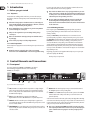
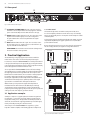
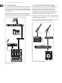
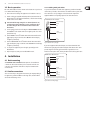
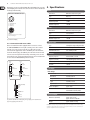
User Manual
SONIC ULTRAMIZER SU9920
Ultimate Stereo Sound Enhancement Processor
2
SONIC ULTRAMIZER SU9920 User Manual
Table of Contents
Thank you........................................................................ 2
Important Safety Instructions....................................... 3
Legal Disclaimer.............................................................. 3
Limited warranty............................................................. 3
1. Introduction................................................................ 4
1.1 Before you get started....................................................... 4
1.1.1 Shipment........................................................................... 4
1.1.2 Initial operation.............................................................. 4
1.1.3 Online Registration....................................................... 4
2. Control Elements and Connections.......................... 4
2.1 Front panel............................................................................. 4
2.2 Rear panel.............................................................................. 5
3. Practical Application.................................................. 5
3.1 Application examples........................................................ 5
3.1.1 Live sound......................................................................... 5
3.1.2 Studio application......................................................... 6
3.1.3 Stage operation with instrument amplifiers........ 6
3.2 Basic operation..................................................................... 7
4. Installation................................................................. 7
4.1 Rack mounting ..................................................................... 7
4.2 Audio connections.............................................................. 7
4.2.1 Cabling with jack cables............................................. 7
4.2.2 Connection with insert cables................................. 8
5. Specifications.............................................................. 8
Thank you
Thank you for purchasing the SONIC ULTRAMIZER SU9920. The SU9920 is a
professional signal processor used to improve the presence and liveliness of
audio signals. For signal processing a combination of a dynamic filter and a
phase delay algorithm is used. The latter is based on psychoacoustic principles
and guarantees improved sound characteristics without unnatural side effects.
The unit works with two independent channels, so you can selectively process
stereo or two mono signals separately from each other. Whether you purchased
the SU9920 for your studio, live sound or the stage, the unit’s sound qualities are
so impressive that you’ll never again want to do without this sound enhancer
when mixing.
We at BEHRINGER hope you enjoy your new acquisition.
3
SONIC ULTRAMIZER SU9920 User Manual
Important Safety
Instructions
Terminals marked with this symbol carry
electrical current of sufficient magnitude
to constitute risk of electric shock.
Use only high-quality professional speaker cables with
¼" TS or twist-locking plugs pre-installed. All other
installation or modification should be performed only
by qualified personnel.
This symbol, wherever it appears,
alerts you to the presence of uninsulated
dangerous voltage inside the
enclosure - voltage that may be sufficient to constitute a
risk of shock.
This symbol, wherever it appears,
alerts you to important operating and
maintenance instructions in the
accompanying literature. Please read the manual.
Caution
To reduce the risk of electric shock, do not
remove the top cover (or the rear section).
No user serviceable parts inside. Refer servicing to
qualified personnel.
Caution
To reduce the risk of fire or electric shock,
do not expose this appliance to rain and
moisture. The apparatus shall not be exposed to dripping
or splashing liquids and no objects filled with liquids,
such as vases, shall be placed on the apparatus.
9. Do not defeat the safety purpose of the polarized
or grounding-type plug. A polarized plug has two blades
with one wider than the other. A grounding-type plug
has two blades and a third grounding prong. The wide
blade or the third prong are provided for your safety. If the
provided plug does not fit into your outlet, consult an
electrician for replacement of the obsolete outlet.
10. Protect the power cord from being walked on or
pinched particularly at plugs, convenience receptacles,
and the point where they exit from the apparatus.
11. Use only attachments/accessories specified by
the manufacturer.
12. Use only with the
cart, stand, tripod, bracket,
or table specified by the
manufacturer, or sold with
the apparatus. When a cart
is used, use caution when
moving the cart/apparatus
combination to avoid
injury from tip-over.
13. Unplug this apparatus during lightning storms or
when unused for long periods of time.
14. Refer all servicing to qualified service personnel.
Servicing is required when the apparatus has been
damaged in any way, such as power supply cord or plug
is damaged, liquid has been spilled or objects have fallen
into the apparatus, the apparatus has been exposed
to rain or moisture, does not operate normally, or has
been dropped.
15. The apparatus shall be connected to a MAINS socket
outlet with a protective earthing connection.
16. Where the MAINS plug or an appliance coupler is
used as the disconnect device, the disconnect device shall
remain readily operable.
Caution
These service instructions are for use
by qualified service personnel only.
To reduce the risk of electric shock do not perform any
servicing other than that contained in the operation
instructions. Repairs have to be performed by qualified
service personnel.
1. Read these instructions.
2. Keep these instructions.
3. Heed all warnings.
4. Follow all instructions.
5. Do not use this apparatus near water.
6. Clean only with dry cloth.
7. Do not block any ventilation openings. Install in
accordance with the manufacturer’s instructions.
8. Do not install near any heat sources such as
radiators, heat registers, stoves, or other apparatus
(including amplifiers) that produce heat.
LEGAL DISCLAIMER
TECHNICAL SPECIFICATIONS AND APPEARANCES
ARE SUBJECT TO CHANGE WITHOUT NOTICE AND
ACCURACY IS NOT GUARANTEED. BEHRINGER,
KLARK TEKNIK, MIDAS, BUGERA, AND TURBOSOUND
ARE PART OF THE MUSIC GROUP (MUSIC-GROUP.COM).
ALL TRADEMARKS ARE THE PROPERTY OF THEIR
RESPECTIVE OWNERS. MUSIC GROUP ACCEPTS NO
LIABILITY FOR ANY LOSS WHICH MAY BE SUFFERED
BY ANY PERSON WHO RELIES EITHER WHOLLY OR
IN PART UPON ANY DESCRIPTION, PHOTOGRAPH
OR STATEMENT CONTAINED HEREIN. COLORS AND
SPECIFICATIONS MAY VARY FROM ACTUAL PRODUCT.
MUSIC GROUP PRODUCTS ARE SOLD THROUGH
AUTHORIZED FULLFILLERS AND RESELLERS ONLY.
FULLFILLERS AND RESELLERS ARE NOT AGENTS OF
MUSIC GROUP AND HAVE ABSOLUTELY NO AUTHORITY
TO BIND MUSIC GROUP BY ANY EXPRESS OR IMPLIED
UNDERTAKING OR REPRESENTATION. THIS MANUAL
IS COPYRIGHTED. NO PART OF THIS MANUAL MAY
BE REPRODUCED OR TRANSMITTED IN ANY FORM
OR BY ANY MEANS, ELECTRONIC OR MECHANICAL,
INCLUDING PHOTOCOPYING AND RECORDING OF ANY
KIND, FOR ANY PURPOSE, WITHOUT THE EXPRESS
WRITTEN PERMISSION OF MUSIC GROUP IP LTD.
ALL RIGHTS RESERVED.
© 2013 MUSIC Group IP Ltd.
Trident Chambers, Wickhams Cay, P.O. Box 146,
Road Town, Tortola, British Virgin Islands
LIMITED WARRANTY
For the applicable warranty terms and conditions
and additional information regarding MUSIC Group’s
Limited Warranty, please see complete details online at
www.music-group.com/warranty.
4
SONIC ULTRAMIZER SU9920 User Manual
1. Introduction
For connection to the mains use the enclosed power cord with cold connector
which complies with the relevant safety regulations.
1.1 Before you get started
◊ Please make sure that all devices are properly grounded. For your own
safety, never remove or disable the ground conductors from the devices
or on the power cords. The unit must always be connected to the mains
outlet with a protective grounding connection.
1.1.1 Shipment
Your product was carefully packed at the factory to ensure safe transport.
Nevertheless, if the box is damaged inspect the unit immediately for signs
of damage.
◊ The tone quality may diminish within the range of powerful radio
◊ If the unit is damaged please do NOT return it to us, but notify your
dealer and the shipping company immediately; otherwise, claims for
damage or replacement may not be granted.
◊ We recommend that you use a flight case to give the unit optimum
broadcasting stations and high-frequency sources. Increase the
distance between the transmitter and the unit, and use shielded cables
for all connections.
1.1.3 Online Registration
Please register your new BEHRINGER equipment right after your purchase
by visiting http://behringer.com and read the terms and conditions of our
warranty carefully.
protection during use or transport.
◊ Always use the original box to prevent damage during storage
or transport.
◊ Make sure that children cannot play unsupervised with the unit or
its packaging.
◊ Please ensure proper disposal of all packing materials.
1.1.2 Initial operation
Ensure adequate air supply and to avoid overheating do not place the unit near
radiators etc.
◊ Blown fuses must be replaced by fuses of the correct rating!
Please refer to the “SPECIFICATIONS” section for the applicable rating.
Should your BEHRINGER product malfunction, it is our intention to have it
repaired as quickly as possible. To arrange for warranty service, please contact
the BEHRINGER retailer from whom the equipment was purchased. Should your
BEHRINGER dealer not be located in your vicinity, you may directly contact
one of our subsidiaries. Corresponding contact information is included in the
original equipment packaging (Global Contact Information/European Contact
Information). Should your country not be listed, please contact the distributor
nearest you. A list of distributors can be found in the support area of our website
(http://behringer.com).
Registering your purchase and equipment with us helps us process your repair
claims more quickly and efficiently.
Thank you for your cooperation!
2. Control Elements and Connections
2.1 Front panel
The control elements for CHANNEL 1 and CHANNEL 2 are identical.
In the following paragraphs the functions are described using
CHANNEL 1 as an example.
(1)
(2)
(3)
(4)
(5)
(6)
Fig. 2.1: Control elements on the front panel
(1) CLIP: This LED is constantly lit when the input level is too high. If it lights
up for a short period of time it is warning you of an impending overdrive.
There is a safety headroom of 3 dBu before the signal becomes distorted.
The LED should not light up.
(2) LEDs: The four LEDs display the output level in 10 dBu steps.
Regular illumination of the 0 dBu LED indicates an optimal output level.
(3) PROCESS: With this control the portion of high-frequency signals to be
processed by the SU9920 is specified. The MAX setting corresponds to a level
boost of +12 dbU at 5 kHz.
(4) LOW CONTOUR: This control adjusts the portion of low-frequency signals to
be processed by the SU9920. The MAX setting corresponds to a level boost of
+12 dbU at 50 kHz.
(5) IN/OUT: With this switch signal processing is activated and deactivated.
The LED lights up in the active operating mode.
(6) POWER: Use the POWER switch to put the unit into operation. The POWER
switch should be in the “Off” position when you connect the unit to the
power feed (mains).
To disconnect the unit from the mains, pull out the power plug. When switching
on the unit ensure that the power plug is easily accessible. To mount the unit in a
rack ensure that the unit can easily be disconnected from the mains by means of
a plug or an all-pole mains switch on the back side.
◊ Please note: Switching the POWER switch off does not disconnect the
unit completely from the mains. For this reason you should unplug the
power cord if the unit is not going to be used for prolonged periods
of time.
5
SONIC ULTRAMIZER SU9920 User Manual
2.2 Rear panel
(8)
(7)
(9)
Fig. 2.2: Control elements on the rear panel
(7) FUSE HOLDER / IEC POWER SOCKET: The mains connection is made via
an IEC male socket. It complies with relevant safety regulations. A suitable
power cord is included. Replace the fuse with a fuse of the same type.
(8) OUTPUTS 1: Balanced XLR sockets and ¼" jacks - these are used to connect
amplifiers as well as further signal processors and recording devices.
The jacks and XLR sockets can be used in parallel when two outputs
are required.
(9) INPUTS 1: Balanced XLR sockets and ¼" jacks - these are used to connect
line-level signal sources (e.g. a mixing console). To avoid interference only
the jacks or the XLR sockets should be used.
SERIAL NUMBER: The serial number can be found on the back right side of
the unit. It is needed for online registration.
3.1.1 Live sound
The SU9920 is ideally suited to use with live sound systems in clubs, discos,
live concerts and public performances. Here the unit not only can considerably
improve the signal quality, but also can compensate for the inadequacies of small
or weak PA systems.
For this application the unit should be installed between the mixing console mix
output and the amplifier input. If a graphic equalizer is also used, it should be
positioned after the SU9920.
Because this application involves stereo processing, channels 1 and 2 must have
the same settings. Otherwise, the original stereo image will be distorted.
B1220 PRO
B1220 PRO
3. Practical Application
The SU9920 belongs to the group of psychoacoustic enhancers which also
includes exciters. These devices can enhance the quality of audio signals.
In contrast to an exciter, the SONIC ULTRAMIZER does not add any new harmonics
to the signal, but rather improves the signal quality by processing the harmonics
in the original material. Through this action the sound is changed more naturally
than it is through harmonic enhancement with an exciter.
The concept behind the SONIC ULTRAMIZER is based on the fact that through
signal modification (as is caused for example, by equalizers and frequency filters),
the original signal is distorted. Through this the time-based sequence of the
fundamental tone and the harmonics, whose correlation is extremely important
for naturally sounding signal reproduction via loudspeakers, is shifted.
Restoring the original time-based relationships between the fundamental tone
and the harmonics thus ideally leads to optimal reproduction of the original
signal and hence a sound which is free from unpleasant distortion.
With the SU9920 you can reproduce the original relationships between
the fundamental tone and the harmonics and additionally boost the high
and low-frequency portions independently of each other. Through this the
transparency of the starting signal is greatly increased and a precise reproduction
of all signals over the entire frequency spectrum is obtained.
EP2000
Outputs 1
SU9920
Outputs 2
Inputs 1
XM8500
Keyboard
Line in 2/3
Main out
3.1 Application examples
Similarly to a compressor or a graphic equalizer, the SU9920 is integrated into
the signal path, i.e. connected in series to mix outputs or integrated into the
insert path of a mixing console. Avoid parallel use in the Aux path, as with an
effects unit, since this mixes the original signal with the processed effect signal,
thereby considerably worsening the sound characteristics.
Inputs 2
Mic 1
The best way to use the SONIC ULTRAMIZER is in a signal chain, e.g. from
keyboard to SU9920 to amplifier, as the following application examples show.
XENYX 1622USB
Fig. 3.1: Use of the SU9920 with live sound systems
6
SONIC ULTRAMIZER SU9920 User Manual
3.1.2 Studio application
3.1.3 Stage operation with instrument amplifiers
In a studio environment the SONIC ULTRAMIZER is ideal for mastering to enhance
the sound of recordings. The SU9920 can lend your music the professional polish
of high-quality productions in just a few steps. Even if you primarily work with a
digital audio workstation, you can perform the final mastering with the SU9920
and an external recorder.
Besides being ideal for use with stereo signals, the SONIC ULTRAMIZER is also
suitable for use with one or two individual signals, e.g. guitars. With electric
guitars it can be used in combination with a combo amp or a separate
modelling processor-amplifier combination to give the guitar sound more
presence, fullness and punch. A similar combination with a keyboard and an
external amplifier is possible. Because the two channels of the SU9920 work
independently, even two different mono signals can be processed.
For this application connect the SU9920 so that it comes before the mastering
recorder. Channels 1 and 2 must have the same settings since this application
involves stereo processing. Otherwise, the original stereo image will be distorted.
Connect the SU9920 with the effects loop connections on your combo amplifier
if it provides for connection in insert mode, i.e. exclusively reproduces the output
signal of the SU9920 via the loudspeaker.
If you are using a modelling processor you must connect the processor output to
the SU9920 input and route the SU9920 signal to the amplifier.
Md Recorder
Outputs 1
SU9920
Outputs 2
Inputs 1
Inputs 2
Electric Guitar
Bass Guitar
Computer
Return
FCA202
XM8500
V-AMP PRO
Send
GMX212
Inputs 1
Outputs 1
Inputs 2
Keyboard
Line in 2/3
Main out
SU9920
Outputs 2
Line 1
BXL3000A
XENYX 1622USB
Fig. 3.2: The SU9920 in Studio mode
Fig. 3.3: The SU9920 in use with guitar amplifiers
7
SONIC ULTRAMIZER SU9920 User Manual
3.2 Basic operation
4.2.1 Cabling with jack cables
Due to the small number of control elements on the SU9920 it is easy to learn to
use it. Perform the following steps:
To operate the SU9920 in series with other equipment, you will need standard
commercial ¼" jack cables, often referred to as instrument cables or patch cables.
1) Connect the unit according to the application as described in section 3.1.
These cables have a ¼" TS jack plug at each end. Connect the inputs of the
equipment with the corresponding outputs of each of the other devices.
2) Switch on all devices (amplifier and loudspeaker last) and ensure that the
IN/OUT switch (5) on the SU9920 is illuminated, i.e. that the unit is working
and all controls are set to ‘MIN’.
◊ First make the following settings for one channel (channel 1 or 2)
according to the input assignment. For stereo applications choose
the same settings for the second channel as those made for the
first channel.
3) Set the signal level on the device feeding the SONIC ULTRAMIZER such that
the CLIP LED (1) on the SU9920 either does not light up at all or for a short
period of time only.
4) Turn the PROCESS control (3) until the desired enhancement effect in the
high-frequency range is achieved or the 0 dBU LED in the level display (2) lights up continuously.
5) Turn the LOW CONTOUR control (4) until the desired enhancement effect
in the low-frequency range is achieved or the 0 dBu LED in the level display (2) lights up continuously.
6) To compare the original and processed signals, repeatedly press the
IN/OUT button.
7) Repeat steps 4) to 6) until you are satisfied with the result.
4. Installation
4.1 Rack mounting
The BEHRINGER SONIC ULTRAMIZER SU9920 requires 1U for installation in
a 19-inch rack. Please make sure that you leave around 10 cm for the rear
connections. For installation of the unit in a rack please use M6 machine
screws and nuts.
4.2 Audio connections
There are various ways to integrate the SU9920 into your setup. Depending on
the application you will need different connecting cables, and these will be
discussed in the following section.
Unbalanced ¼" TS connector
strain relief clamp
sleeve
tip
sleeve
(ground/shield)
tip
(signal)
Fig. 4.1: Unbalanced ¼" TS jack plugs
If your other equipment has balanced inputs, use a balanced switched cable
with two stereo jack plugs at the balanced outputs of the SU9920. These cables
provide a high level of security against interference signals such as noise
interference from power cables, and they should be used for all long cable routes.
Balanced ¼" TRS connector
strain relief clamp
sleeve
ring
tip
sleeve
ground/shield
ring
cold (-ve)
tip
hot (+ve)
For connection of balanced and unbalanced plugs,
ring and sleeve have to be bridged at the stereo plug.
Fig. 4.2: Balanced ¼" TRS jack plugs
8
SONIC ULTRAMIZER SU9920 User Manual
Alternatively, you can use professional XLR cables with an XLR socket on one side
and an XLR plug on the other side. This cable connection is the most reliable both
electrically and mechanically.
Balanced use with XLR connectors
5. Specifications
Inputs
Connections
XLR sockets and ¼" stereo jacks
TypeBalanced
2 1
3
input
1 = ground/shield
2 = hot (+ve)
3 = cold (-ve)
1
Input impedance
20 kΩ balanced, 10 kΩ unbalanced
Nominal input level
+4 dBu
Maximum input level
+22 dBu
Outputs
2
3
Connections
XLR sockets and ¼" stereo jacks
output
TypeServo-balanced
For unbalanced use, pin 1 and pin 3
have to be bridged
Output impedance
60 Ω balanced, 60 Ω unbalanced
Maximum output level
+22 dBu
Fig. 4.3: Balanced XLR plug
4.2.2 Connection with insert cables
Please use standard insert cables equipped with ¼" connectors to connect
the SONIC ULTRAMIZER to the insert path of a mixing console. These Y cables
have two ¼" TS connectors at one end, and one ¼" TRS connector at the
other. Connect the plug marked “Send” to the INPUT L jack on the effects unit.
Connect the “Return” plug to the OUTPUT L jack on the device. Connect the TRS
connector to the insert jack of the channel strip on the mixing console. Use two
insert cables for stereo sub-groups and main-mix inserts. The second cable must
be connected to the INPUT/OUTPUT R jacks of the SU9920.
Return
(out)
Send
(in)
tip
signal
tip
signal
sleeve
ground/shield
sleeve
ground/shield
tip
tip
sleeve
strain relief clamp
sleeve
strain relief clamp
Enhancer Section
Type
3-band phase delay and dynamic filter
PROCESS control
max. 12 dBu @ 5 kHz
LOW CONTOUR control
max. 12 dBu @ 50 kHz
System Data
Frequency response
25 Hz to 50 kHz, +/-3 dB
Signal-to-noise ratio
>95 dB, unweighted, 20 Hz to 20 kHz
Distortion (THD + N)
0.05% typ. @ +4 dBu, 1 kHz (IN/OUT)
Crosstalk
>75 dB
Power Supply
Mains Voltage
strain relief clamp
sleeve
ring
tip
USA/Canada
120 VAC, 60 Hz
China/Korea
220 VAC, 50/60 Hz
Europe/UK/Australia
230 VAC, 50 Hz
Japan
100 VAC, 50-60 Hz
Export model
120/230 VAC, 50-60 Hz
Power consumption
approx. 12 W
Fuse
100-120 VAC: T 250 mA, H 250 V
220-240 VAC: T 125 mA, H 250 V
sleeve
ground/shield
ring
return (in)
tip
send (out)
Fig. 4.4: Insert cable with one ¼" TRS (tip-ring-sleeve) jack plug on one end and two ¼" TS
(tip-sleevel) jack plugs on the other end.
Dimensions/Weight
Dimensions (H x W x D)
approx. 8.5 x 1.8 x 19''
approx. 217 x 44.5 x 483 mm
Weight
approx. 4.84 lbs / 2.20 kg
BEHRINGER is constantly striving to maintain the highest professional standards. As a result of these efforts,
modifications may be made from time to time to existing products without prior notice. Specifications and
appearance may differ from those listed or illustrated.
We Hear You