1
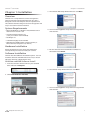
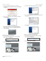
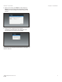
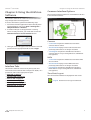
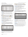
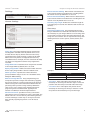
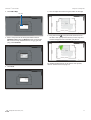
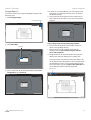
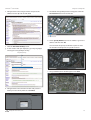
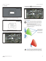
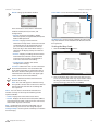
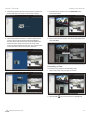
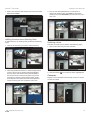
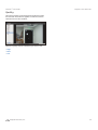
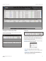
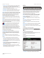
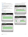
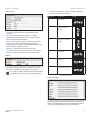
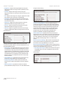
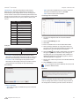
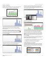
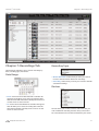
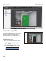
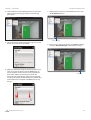
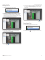
For
IP Camera/NVR
Management System
use with the following airCam models:
airVision™ User Guide
Table of Contents
Table of Contents
Chapter 1: Installation . . . . . . . . . . . . . . . . . . . . . . . . . . . . . . . . . . . . . . . . . . . . . . 1
Overview. . . . . . . . . . . . . . . . . . . . . . . . . . . . . . . . . . . . . . . . . . . . . . . . . . . . . . . . . . . . . . . . . . . . . . . . . 1
System Requirements . . . . . . . . . . . . . . . . . . . . . . . . . . . . . . . . . . . . . . . . . . . . . . . . . . . . . . . . . . . . 1
Hardware Installation . . . . . . . . . . . . . . . . . . . . . . . . . . . . . . . . . . . . . . . . . . . . . . . . . . . . . . . . . . . . . 1
Software Installation. . . . . . . . . . . . . . . . . . . . . . . . . . . . . . . . . . . . . . . . . . . . . . . . . . . . . . . . . . . . . . 1
Chapter 2: Using the AirVision Software . . . . . . . . . . . . . . . . . . . . . . . . . . . . . 6
Interface Tabs . . . . . . . . . . . . . . . . . . . . . . . . . . . . . . . . . . . . . . . . . . . . . . . . . . . . . . . . . . . . . . . . . . . . 6
Common Interface Options . . . . . . . . . . . . . . . . . . . . . . . . . . . . . . . . . . . . . . . . . . . . . . . . . . . . . . . 6
Chapter 3: Map Tab . . . . . . . . . . . . . . . . . . . . . . . . . . . . . . . . . . . . . . . . . . . . . . . . 10
Adding a Map . . . . . . . . . . . . . . . . . . . . . . . . . . . . . . . . . . . . . . . . . . . . . . . . . . . . . . . . . . . . . . . . . . .10
Chapter 4: Live View Tab . . . . . . . . . . . . . . . . . . . . . . . . . . . . . . . . . . . . . . . . . . . 17
Views . . . . . . . . . . . . . . . . . . . . . . . . . . . . . . . . . . . . . . . . . . . . . . . . . . . . . . . . . . . . . . . . . . . . . . . . . . .17
Cameras . . . . . . . . . . . . . . . . . . . . . . . . . . . . . . . . . . . . . . . . . . . . . . . . . . . . . . . . . . . . . . . . . . . . . . . .19
Quality . . . . . . . . . . . . . . . . . . . . . . . . . . . . . . . . . . . . . . . . . . . . . . . . . . . . . . . . . . . . . . . . . . . . . . . . . .20
Chapter 5: Devices Tab . . . . . . . . . . . . . . . . . . . . . . . . . . . . . . . . . . . . . . . . . . . . 21
Cameras . . . . . . . . . . . . . . . . . . . . . . . . . . . . . . . . . . . . . . . . . . . . . . . . . . . . . . . . . . . . . . . . . . . . . . . .21
NVRs . . . . . . . . . . . . . . . . . . . . . . . . . . . . . . . . . . . . . . . . . . . . . . . . . . . . . . . . . . . . . . . . . . . . . . . . . . . .22
Chapter 6: Statistics Tab . . . . . . . . . . . . . . . . . . . . . . . . . . . . . . . . . . . . . . . . . . . 28
Activity Distribution (Last 24 Hours) . . . . . . . . . . . . . . . . . . . . . . . . . . . . . . . . . . . . . . . . . . . . . .28
Disk Usage (NVR) . . . . . . . . . . . . . . . . . . . . . . . . . . . . . . . . . . . . . . . . . . . . . . . . . . . . . . . . . . . . . . . .28
Camera Activity (Last 24 Hours) . . . . . . . . . . . . . . . . . . . . . . . . . . . . . . . . . . . . . . . . . . . . . . . . . .29
NVR Load (NVR) . . . . . . . . . . . . . . . . . . . . . . . . . . . . . . . . . . . . . . . . . . . . . . . . . . . . . . . . . . . . . . . . .29
Chapter 7: Recordings Tab . . . . . . . . . . . . . . . . . . . . . . . . . . . . . . . . . . . . . . . . . 31
Date Range. . . . . . . . . . . . . . . . . . . . . . . . . . . . . . . . . . . . . . . . . . . . . . . . . . . . . . . . . . . . . . . . . . . . . .31
Recording Type. . . . . . . . . . . . . . . . . . . . . . . . . . . . . . . . . . . . . . . . . . . . . . . . . . . . . . . . . . . . . . . . . .31
Devices . . . . . . . . . . . . . . . . . . . . . . . . . . . . . . . . . . . . . . . . . . . . . . . . . . . . . . . . . . . . . . . . . . . . . . . . .31
Recordings View . . . . . . . . . . . . . . . . . . . . . . . . . . . . . . . . . . . . . . . . . . . . . . . . . . . . . . . . . . . . . . . .32
Chapter 8: Analytics Tab . . . . . . . . . . . . . . . . . . . . . . . . . . . . . . . . . . . . . . . . . . . 33
Creating a New Zone . . . . . . . . . . . . . . . . . . . . . . . . . . . . . . . . . . . . . . . . . . . . . . . . . . . . . . . . . . . .33
Editing a Zone . . . . . . . . . . . . . . . . . . . . . . . . . . . . . . . . . . . . . . . . . . . . . . . . . . . . . . . . . . . . . . . . . . .35
Deleting a Zone . . . . . . . . . . . . . . . . . . . . . . . . . . . . . . . . . . . . . . . . . . . . . . . . . . . . . . . . . . . . . . . . .35
Appendix A: Contact Information . . . . . . . . . . . . . . . . . . . . . . . . . . . . . . . . . . 36
Ubiquiti Networks Support . . . . . . . . . . . . . . . . . . . . . . . . . . . . . . . . . . . . . . . . . . . . . . . . . . . . . .36
Ubiquiti Networks, Inc.
i
airVision™ User Guide
Chapter 1: Installation
Chapter 1: Installation
3. The airVision NVR Setup Wizard will start. Click Next.
Overview
airVision™ is a comprehensive camera management
software solution from Ubiquiti Networks, Inc. that is
designed to work with Ubiquiti’s airCam™ product line.
The software interface design is based on the popular and
easy to use UniFi™ software interface.
System Requirements
! Microsoft Windows 7, Windows Vista, Windows XP or
Ubuntu Linux version 11.04
4. You must click I agree to accept the license agreement
and continue.
! Java Runtime Environment 1.6
(1.6.0_26 or above recommended)
! FlashPlayer 10
! 2 GB RAM is highly recommended
! Web Browser: Mozilla Firefox, Google Chrome, or
Microsoft Internet Explorer 8 (or above)
Hardware Installation
Follow the directions in the Quick Start Guide that
accompanied your airCam to install your camera.
5. Be sure that Start AirVision NVR after installation is
selected and click Finish.
Software Installation
airVision has three different installation options. You can
install the airVision and NVR software at once, or install
either the airVision or NVR software only.
AirVision and NVR Software Install
1. Insert the airVision software CD into your CD-ROM
drive and launch Setup.exe.
6. The airVision Setup Wizard will start. Click Next.
2. Click Install AirVision with NVR.
7. You must click I agree to accept the license agreement
and continue.
Ubiquiti Networks, Inc.
1
airVision™ User Guide
8. If your computer doesn’t have Java 1.6 or above
installed, you will be prompted to install it. Click Install
to continue.
9. Be sure that Start AirVision after installation is selected
and click Finish.
Chapter 1: Installation
3. The airVision NVR Setup Wizard will start. Click Next.
4. You must click I agree to accept the license agreement
and continue.
5. Click Finish.
10. The airVision software startup will begin. When the
option becomes available, click Launch a Browser to
Access AirVision.
NVR Software Install Only
1. Insert the airVision software CD into your CD-ROM
drive and launch Setup.exe.
AirVision Software Install Only
1. Insert the airVision software CD into your CD-ROM
drive and launch Setup.exe.
2. Click Install AirVision with NVR.
2. Click Install NVR only.
Ubiquiti Networks, Inc.
2
airVision™ User Guide
3. The airVision Setup Wizard will start. Click Next.
Chapter 1: Installation
2. Launch the airVision software using one of the
following methods:
! Start > Programs
! airVision desktop icon.
4. You must click I agree to accept the license agreement
and continue.
3. The airVision software startup will begin. When the
option becomes available, click Launch a Browser to
Access AirVision.
5. Click Finish.
Configuring the airVision Software
1. You may receive a security certificate warning, click
Proceed anyway.
Launching the airVision Software
If you selected Start AirVision after installation when you
installed the software, airVision will launch automatically.
When you need to launch the software again or if you
didn’t select the option, you can launch airVision via the
following methods.
1. Launch the NVR software (if it isn’t already running)
using one of the following methods:
1. Select your language and click Next.
! Start > Programs
! airVision NVR desktop icon.
Ubiquiti Networks, Inc.
3
airVision™ User Guide
Chapter 1: Installation
2. Enter an admin name and password to use when
accessing the management interface. Confirm your
password in the Confirm field. Click Next.
5. The first detected camera will appear. You will need to
enter the User Name and Password for the camera to
begin managing it.
3. The first detected NVR (Network Video Recorder) will
appear. Select an NVR and click manage.
6. Assign the camera to an NVR from the drop-down list
and click manage. Use the Prev Camera and Next
Camera to view detected cameras. Select the cameras
that you want to manage.
4. When a NVR has been successfully managed, it will
appear highlighted green. If you have multiple NVRs,
use the Prev NVR and Next NVR buttons to navigate
through the detected NVRs. Click manage for each
additional NVR that you want to include. Click Next.
Ubiquiti Networks, Inc.
7. When a camera has been successfully managed, it
will appear highlighted green. Once you’ve finished
managing cameras, click Next.
4
airVision™ User Guide
Chapter 1: Installation
8. Review your settings. Click Back to make changes or
Finish to save your settings. Once finished you will be
redirected to the management interface via your web
browser.
9. A login screen will appear for the airVision
management interface. Enter the admin name and
password that you created and click Login.
Proceed to the next chapter for information on using the
airVision software.
Ubiquiti Networks, Inc.
5
airVision™ User Guide
Chapter 2: Using the AirVision
Software
Chapter 2: Using the AirVision Software
Common Interface Options
The common interface options are accessible from all tabs
in the airVision interface.
The airVision software has a browser-based interface for
easy configuration and management.
To access the interface, perform the following steps:
1. Launch the airVision application if hasn’t already been
started. Windows users go to Start > All Programs >
Ubiquiti airVision > AirVision.
2. A window will open as the application is starting.
Once it is ready to launch, you will be able to click the
Launch a Browser to access AirVision button.
Cameras
! connected Drop-down clickable list of all of the
cameras that are online.
3. The login screen will appear. Enter the admin name and
password in the appropriate fields and click Login.
! disconnected Displays a list of cameras that were
previously online but are no longer accessible.
! unmanaged Drop-down clickable list of all of the
cameras that are not yet managed but are available for
management.
NVRs
! connected Drop-down clickable list of all of the NVRs
that are online.
Interface Tabs
The airVision software consists of six primary tabs. This
User Guide covers each tab with a chapter. For details, on a
specific tab, refer to the appropriate chapter.
! “Map Tab” on page 10
! “Live View Tab” on page 17
! disconnected Displays a list of NVRs that were
previously online but are no longer accessible.
! unmanaged Drop-down clickable list of all of the
NVRs that are not yet managed but are available for
management.
Time/Date/Logout
The current time and date are displayed on the screen.
! “Devices Tab” on page 21
! “Statistics Tab” on page 28
Logout Click this icon to logout of airVision.
! “Recordings Tab” on page 31
! “Analytics Tab” on page 33
Ubiquiti Networks, Inc.
6
airVision™ User Guide
Recent Recordings
Displays a list of recent recordings including the date and
time the recording occurred and camera and details.
Chapter 2: Using the AirVision Software
Designated recordings all appear under the
Recordings tab. If you wish to remove a recording, simply
click the next to the recording and it will be removed
from the list. This doesn’t delete the actual recordings, it
just removes the entries from this list.
Time Occurred Displays the date and time that
the recording took place. The year/month/day and
hour:minute:seconds are displayed.
Info Displays the type of recording and camera
information. It is a clickable link that will launch the Viewer
and play the recording when clicked.
Type The type of event.
Clear Clears the list of Recent Recordings. This doesn’t
delete the actual recordings, it just removes the entries
from this list.
Search Allows you to search for specific text. Simply
begin typing, there is no need to press enter. The results
are filtered in real-time as soon as you type two or more
characters.
Functions like a bookmark or favorite that is accessible
under the Recordings tab. Click on the Star icon to
the left of the recording to designate a recording. Once
a recording has been designated, the star will appear
yellow in color. To remove the designation, simply click on
the star icon again.
Time Occurred Displays the date and time that
the recording took place. The year/month/day and
hour:minute:seconds are displayed.
Info Displays the type of recording and camera
information. It is a clickable link that will launch the Viewer
and play the recording when clicked.
Type The type of event.
Camera Displays the name of the camera that captured
the recording. It is a clickable link that will open the
Camera Details window. For details on the Camera Details
window, refer to “Camera Details Window” on page 22.
Recordings
Camera Displays the name of the camera that captured
the event. It is a clickable link that will open the Camera
Details window. For details on the Camera Details window,
refer to “Camera Details Window” on page 22.
Alerts
Recent/All Toggle between recent alerts or a list of all
alert messages.
Search Allows you to search for specific text. Simply
begin typing, there is no need to press enter. The results
are filtered in real-time as soon as you type two or more
characters.
Time Occurred Displays the date and time that the event
took place. The year/month/day and hour:minute:seconds
are displayed.
Message Details of the alert are listed here. Some
messages contain clickable links which are underlined and
gray. These links will open the device details window.
Actions Allows you to archive alert messages.
Search Allows you to search for specific text. Simply
begin typing, there is no need to press enter. The results
are filtered in real-time as soon as you type two or more
characters.
Ubiquiti Networks, Inc.
7
airVision™ User Guide
Settings
Camera Settings
Chapter 2: Using the AirVision Software
Event Frame Pre Padding When motion is detected, this
is the amount of frames included in the recording before
the motion occurs. By default this is set to 30.
Event Frame Post Padding When motion is detected, this
is the amount of frames included in the recording after the
motion occurs. By default this is set to 30.
Recording Clip Length Defines the maximum length of
a recording clip in seconds. The default is 600 seconds (10
minutes).
Timestamp
Timestamp Label Format The timestamp label on the
image is defined here. If the field is left blank, there will be
no timestamp on your images. Below is a list of strings that
can be used to create custom timestamp information. The
strings are case sensitive. You can separate the strings with
dividing characters such as spaces, slashes, dashes, and
colons.
String
%N
Performance
Frame Skip This option determines how many frames
are skipped in recorded events. By default this is set to
0 which doesn’t skip any frames and means that every
captured frame is saved. Entering a number in this field
defines how many frames are skipped between every
recorded frame. For example, if 2 were entered in this field,
two frames are skipped in between every single frame
recorded.
Image Buffer Size Determines how many frames are held
in the image buffer. By default, this is set to 40.
Replay Image Buffer Defines the total number of frames
for the replay image buffer. 1000 is the default value.
Warm Up Frames Specifies the number of frames
processed before analysis occurs. 25 is the default value.
Analysis & Recording
Reference Image Blend % Every analyzed image is a
composite of previous images and is formed by applying
the current image as a certain percentage of the previous
reference image. The value entered here determines the
percentage of the previous image used. By default the
value is set to 10%. A higher value would make slower
progressing events less detectable. Typically if this
number is modified, it should be adjusted down.
Displays
Camera Name
%Y
Year (Full)
%y
Year (2 digit)
%m
Month (2 digit)
%d
Day (2 digit)
%D
Date (yy/mm/dd)
%H
Hour
%h
Month (3 letter)
%M
Minute
%S
Second
%f
hundredths of a second
%T
Time (hh:mm:ss)
Examples:
String
Example:
%N - %y/%m/%d %H:%M:%S
Camera - 11/07/18 17:14:25
%N - %D %T
Camera - 11/07/18 17:15:25
! X Location The X value adjusts the position of the
timestamp on the image to the left or right. A value of 0
positions the timestamp on the left side of the image.
! Y Location The Y value adjusts the position of the
timestamp on the image to the top or bottom. A value
of 0 positions the timestamp on top of the image.
Alarm Frame Count Specifies how many consecutive
alarm frames must occur before an event is generated. The
default value of 1 ensures that any alarm frame generates
an event. Although a value of up to 16 may be entered
here, typically anything larger than 3 or 4 will not be
useful.
Ubiquiti Networks, Inc.
8
airVision™ User Guide
Chapter 2: Using the AirVision Software
Admin Settings
Admin Name Displays the current admin name used
to login. To change the admin name, simply enter a new
name and click Apply.
Password A new password can be entered in this field. Be
sure to enter the password again in the Confirm field and
then click Apply to save your new password.
Confirm Used to confirm your new password.
Language Selects the language for use in the interface.
Admin
Server Information
Version The software version is displayed here. If there
is an update, airVision will automatically download it and
display it here.
Support Info
Download Support Info Select this option to download
a file to your computer with information about your
configuration that can be emailed to our support team.
Ubiquiti Networks, Inc.
9
airVision™ User Guide
Chapter 3: Map Tab
The airVision software allows you to upload map images
of your location or use Google Maps™ for a visual
representation of your camera layout. When you initially
launch airVision, a default sample map is displayed.
Chapter 3: Map Tab
Adding a Map
You can add an image you’ve created as a map image
or use Google Maps™ to generate an image for use as a
background.
Image Maps
To add a custom map, you must first create the image
using an illustration, image editing, or blueprint
application that exports .jpg, .gif, or .png file formats.
Once you’ve created the map, you can upload it to the
airVision software by performing the following steps:
1. Click Configure Maps.
Configure Maps button
Ubiquiti Networks, Inc.
10
airVision™ User Guide
2. Click Add a Map.
Chapter 3: Map Tab
5. You can adjust the zoom using the slider on the right.
Add a Map
3. Enter a map name in the Description field and click
Upload my own. Click the Browse button to locate the
file to use as a map (valid file formats are .jpg, .gif, and
.png). Click Continue.
6. Drag the Camera
icon(s) from the Cameras list on
the left to the appropriate location(s) on the map. The
camera will appear in the area that you place it.
For additional information on the camera icon options,
refer to “Camera Icons” on page 14.
4. Click Close.
Ubiquiti Networks, Inc.
11
airVision™ User Guide
Chapter 3: Map Tab
Google Maps™
To create a custom map using Google Maps™, perform the
following steps:
1. Click Configure Maps.
Configure Maps button
4. In order to use Google Maps™, you must register with
Google for a Google Maps API key. To do so, perform
the following steps:
a. Copy and paste the web link from the window into a
new web browser window. Do not close the airVision
window.
http://code.google.com/apis/maps/signup.html
2. Click Add a Map.
Add a Map
b. You need to be signed in with a Google account to
obtain a Google Maps API key.
c. Review the terms and conditions and click the
checkbox next to I have read and agree with the
terms and conditions.
d. Navigate back to the airVision window and copy the
address that airVision displays in the address bar.
You only need to copy until the end of the address, do
not include the port information. In the example below,
the full address is https://192.168.0.245:7443/manage.
You only need to copy up to https://192.168.0.245. Do
not include the colon or anything beyond it.
Address to copy
3. Enter a map name in the Description field and click Use
Google Maps. Click Continue.
Ubiquiti Networks, Inc.
12
airVision™ User Guide
e. Navigate back to the Google window and paste the
address into the My web site URL: field.
Chapter 3: Map Tab
5. The default Google Map location will appear. Click the
Set Location button in the lower left.
Set Location button
6. Select Specify Address to enter an address. Type in the
address and then click Go.
f. Click the Generate API Key button.
You also have the Specify Coordinates option to enter
the latitude and longitude of a specific location.
g. A new window will open displaying your key. Highlight
and copy the Google Maps API key.
Google Maps API Key
7. The specified location should appear. Click Save.
h. Navigate back to the airVision window and paste the
API Key into the API Key field. Click continue.
Ubiquiti Networks, Inc.
13
airVision™ User Guide
8. Click Close.
Chapter 3: Map Tab
11. Drag the Camera
icon(s) from the Cameras list on
the left to the appropriate location(s) on the map.
9. Select the new map you created from the Map
drop-down.
Camera Icons
Camera The Camera icon(s) can be placed on
the map to show the location of the camera(s).
Click and hold the icon to drag the camera to
another location on the map.
Click on the Camera icon to reveal additional
options. Click a blank area of the map to hide
the additional options.
Details icon
Adjustable Camera Field
allows you to define the
visual representation of
the camera field of view.
Lock icon
10. You can adjust the zoom using the slider on the right. .
Note: This doesn’t adjust
the view of the camera.
Remove icon
Live Feed icon
Alert icon
Lock Locks the selected camera to the current
location on the map and disables the Remove
icon functionality for this camera while locked.
Ubiquiti Networks, Inc.
14
airVision™ User Guide
Details Brings up the Details window.
Chapter 3: Map Tab
Zoom Slider Use to zoom the map detail in and out.
There are 4 tabs to select from in the Details
window. Details, Monitor, Archive, and
Configuration.
! Details Displays the IP Address, Model,
Firmware, Uptime, Assigned NVR, NVR IP, and
Mode of NVR operation.
! Monitor Displays camera transmit
information in kbps when Camera Connection
is selected. This can be viewed real-time or
you can select the information for the last
hour, last day, or last week. When Activity is
selected, it will display activity from the last
24 hours.
Set Map Scale Use this option to define the scale of the
map. You will draw a line and define the distance that the
line represents.
Setting the Map Scale
1. Click the Set Map Scale
button.
! Archive Displays recordings that have been
archived for the selected camera. The date
and time of the recording are displayed as
well as the cause for the recording.
! Configuration Displays the camera
configuration settings.
Live Feed Click on this icon to view a live feed
of the selected camera. You can double-click
in the live feed window to expand the view to
full screen. Double-click again to return to the
minimized view. Click the X in the upper right
corner to close the Live Feed window.
Remove Remove the Access Point from the
location on the map.
Alert This icon will appear to indicate activity
for a specific camera. Click on the icon to launch
the Event Viewer and view the recording that
was captured.
2. Click and hold to draw a line in the area that you want
to use to set the scale of the map. If you need to redraw
the line, just click and hold again to draw a new line.
Once you’re happy with the line, click Next.
Show: You can select to show labels or details and
wireless coverage on the map. The following are the
options available:
! Labels Displays the name of the Access Point.
! Details Displays the Access Point name, MAC address,
transmit/receive channel, number of users connected,
and number of guests connected.
Map: If multiple maps have been uploaded, you can
select which map you want to view using this option.
Configure Maps Use this option to add maps or edit the
current map(s).
Ubiquiti Networks, Inc.
15
airVision™ User Guide
Chapter 3: Map Tab
3. Enter the distance that the line represents in the
Distance: field. The distance is specified in meters by
default but you can switch to feet using the drop-down
selection menu on the right. Click Confirm.
Ubiquiti Networks, Inc.
16
airVision™ User Guide
Chapter 4: Live View Tab
The Live View tab provides access to your live camera
feeds. You can view individual cameras or create custom
multiple camera views.
Chapter 4: Live View Tab
Views
Custom views can be created to allow you to monitor
multiple cameras from a single view.
Create a New View
To create a new camera view, perform the following steps:
1. Click Create a New View under Views.
Note: Camera streams are viewable without
assigning the camera to an NVR but for optimal
performance, cameras should be assigned it to a
monitor.
Ubiquiti Networks, Inc.
17
airVision™ User Guide
Chapter 4: Live View Tab
2. Click-drag a camera from the list of Cameras to the area
on the right that says “Drag a camera here to begin”.
4. To finalize your camera view, click Save New in the
lower right corner.
3. Click-drag additional cameras to the desired positions
on the screen. A blue position indicator highlights
the area where the camera will be placed. Release the
mouse to lock a camera into place. The scale of the
camera is determined by the location it is placed on the
screen and the number of cameras in the view.
5. Enter a name for the camera view in the View label: field
and click Save.
Renaming a View
To rename a view, perform the following steps:
1. Click on the view that you want to rename.
2. Click the Edit
Ubiquiti Networks, Inc.
icon on the line that is highlighted.
18
airVision™ User Guide
3. Enter a new name for the camera view in the View label:
field and click Save.
Chapter 4: Live View Tab
3. You can save the updated view as a new view or
replace the existing view. Click Save to replace the
existing view. Click Save New if you want to save it as a
new view.
Adding Cameras to an Existing View
To add cameras to an existing view, perform the following
steps:
Deleting a View
1. Click on the view that you want to add cameras to.
To delete an existing view, perform the following steps:
1. Click on the view that you want to delete.
2. Click-drag additional cameras to the desired positions
on the screen. A blue position indicator highlights
the area where the camera will be placed. Release
the mouse to lock a camera into place. If you want
to replace an existing camera with another, simply
click-drag the new camera from the list and place it
over the camera you want to replace in the view.
Ubiquiti Networks, Inc.
2. Click the Delete
icon on the line that is highlighted.
Cameras
Displays a list of available camera feeds. Click on a camera
to view a live feed.
19
airVision™ User Guide
Chapter 4: Live View Tab
Quality
The camera quality can be changed at the bottom of the
Live View tab. This selection applies to all of the cameras
viewed in the Live View window.
Select the quality of the live feed that you want to use.
! High
! Med
! Low
Ubiquiti Networks, Inc.
20
airVision™ User Guide
Chapter 5: Devices Tab
Chapter 5: Devices Tab
Cameras
The Devices tab displays two device separate lists. One for
cameras and one for NVRs.
Cameras are displayed with their name, operation mode,
the connected NVR, IP address, throughput, last recording
date and time, camera status, and an action button to
locate the camera on the map and another action button
to view the live feed of the camera.
Add Camera Click this button to add a camera manually.
The Add Camera window will appear.
! Alias This is the friendly name of the camera.
! Hostname Displays the host name or IP address of the
camera.
! HTTP Protocol Drop-down allows you to select
between HTTP or HTTPS access to the camera. HTTPS
offers encrypted communication.
Ubiquiti Networks, Inc.
21
airVision™ User Guide
! HTTP(s) Port The port used for HTTP or HTTPS access
to the camera. The standard default port for HTTP
communication is port 80. The standard default port for
HTTPS communication is port 443.
Chapter 5: Devices Tab
NVRs
! RTSP Port The RTSP port is typically port 554.
! User Name The user name used to access the camera.
! Password The password used to access the camera.
Search Allows you to search the tables for specific search
criteria. Any text that is entered is used as real-time search
criteria and anything that doesn’t match the entered
characters will be removed from the view. Delete the
search string to return to a normal view.
Camera Displays the name of the camera. Click on the
name to open the Camera Details window for the specific
camera.
Mode Displays the operation mode that the camera is in.
NVR Displays the NVR that is being used for recordings
by the camera. Click on the name to open the NVR Details
window for the specific NVR.
Note: An NVR will also automatically downscale
attached cameras when viewing the live feed.
Search Allows you to search the tables for specific search
criteria. Any text that is entered is used as real-time search
criteria and anything that doesn’t match the entered
characters will be removed from the view. Delete the
search string to return to a normal view.
NVR Displays the alias or IP address of the NVR. Click on
the name to open the NVR Details window of the NVR.
Cameras Displays the number of cameras that are
connected to the NVR.
Hostname Displays the hostname or IP address of the
NVR.
CPU Usage Displays the percentage value of the CPU
being utilized by the NVR.
Disk Usage Displays the amount of disk space being
used.
Memory Free Displays the amount of memory available.
Status Displays the connection status information.
Hostname Displays the hostname of the camera.
Click the hostname to access the camera configuration
interface of the selected camera. The login screen for the
camera configuration will appear. Refer to the airCam
Camera Configuration Interface User Guide located on the
CD-ROM for interface details.
Tx Displays the camera throughput.
Actions Allows you to manage an NVR or edit the config
settings.
Clicking on a Device Link
The recordings have clickable links underlined in gray
text for recordings and cameras. Details vary based on the
selection.
Last Recording Displays the date and time of the last
recording made by the camera. Click it to view the last
recording and the Event Viewer will open and play the
recording.
Camera Details Window
Status Displays the connection status information.
Details
Actions Select an action button to perform the desired
action:
Displays details on the selected camera.
The upper part of the window has 4 clickable tabs. The 4
tabs contain the following information:
Overview
! Locate Click this button to locate the camera on
the map. You will be taken to the map screen and an
animation will indicate which camera it is on the map.
! Live Feed Click this button to view a live feed from the
selected camera.
! Config Click this button to open that camera’s
configuration details. Refer to “Configuration” on page
24 for additional details.
! Manage Click to manage a camera that is currently
unmanaged by airVision. You will need to enter the user
name and password for the camera.
! IP address Displays the IP address of the camera.
Ubiquiti Networks, Inc.
22
airVision™ User Guide
! Model Displays the camera model information.
! Firmware Displays the version of software used on the
camera.
Chapter 5: Devices Tab
! 1 Day Displays a chart of the camera transmission
information for the last day. The chart displays the low,
average, and high transmission information in kbps.
! Uptime Displays the amount of time the camera has
been running without interruption.
! Assigned NVR Displays the name of the NVR that the
camera has been assigned to.
! NVR IP Displays the IP address of the NVR.
! Mode Displays the recording mode of operation that
the camera is using.
Monitor
Monitor has two selectable options below it:
Camera Connection
! Realtime Displays real-time camera transmission
information in kbps.
! 1 Week Displays a chart of the camera transmission
information for the last day. The chart displays the low,
average, and high transmission information in kbps.
! 1 Hour Displays camera transmission information for
the last hour in kbps.
Ubiquiti Networks, Inc.
23
airVision™ User Guide
Activity
Chapter 5: Devices Tab
Configuration
Displays activity from the last 24 hours.
Archive
Basic Configuration
! Alias This field defines the name of the camera.
! NVR Assignment Defines the NVR that the selected
camera is assigned to.
! Date Displays the date and time of the recording.
! Cause Displays the cause of the recording.
! Record Mode Allows you to define the recording
mode of the camera on the NVR. Below are the available
options:
Record Mode
Description
Off
No recording or events generated in this mode.
Monitor
In Monitor mode, no image analysis is done and
no events are generated. In Monitor mode, the
NVR will downscale live feeds to suit the users
feed size/quality settings.
Motion Detect
In Motion Detect mode, all captured images are
analyzed and events are generated when motion
is detected.
Full Time Record
In Full Time Record mode, continuous events of a
fixed length are generated regardless of motion
which is similar to a time-lapse video recorder.
There is no motion detection used in this mode.
Motion Record
Motion Record mode uses elements from Motion
Detect and Full Time Record modes by recording
fixed length events and highlighting any motion
detected within those events.
Recording Modes
Ubiquiti Networks, Inc.
24
airVision™ User Guide
Connection
Chapter 5: Devices Tab
! Orientation Defines the image orientation. Below are
the options for image orientation.
Orientation
Description
Normal
Displays the video feed in
normal mode.
Rotate Right
Rotates the entire video
feed to the right 90
degrees.
Rotate Left
Rotates the entire
video feed to the left 90
degrees.
Flip Horizontally
Flips the entire image
horizontally.
Flip Vertically
Flips the entire image
vertically.
Inverted
Flips the entire image
horizontally and vertically.
Example
! Host Name The host name is the IP address of the
camera.
! HTTP Protocol Drop-down allows you to select
between HTTP or HTTPS access to the camera. HTTPS
offers encrypted communication.
! HTTP(s) Port The port used for HTTP or HTTPS access
to the camera. The standard default port for HTTP
communication is port 80. The standard default port for
HTTPS communication is port 443.
! RTSP Port The RTSP port is typically port 554.
! User Name The user name used to access the camera.
! Password The password used to access the camera.
Source
! Resolution Displays the current resolution setting for
the camera and allows you to change the setting.
Note: The resolution selected must be supported on
the camera or the image may not appear properly.
Image Orientation Options
Image Settings
The image settings can be adjusted using the adjustment
sliders. Click View Feed to view a live feed of the camera to
view your settings adjustments as you make them.
Ubiquiti Networks, Inc.
25
airVision™ User Guide
! Brightness Adjusts the image brightness using the
adjustment slider. The range is from 0 (darkest) to 100
(brightest).
Chapter 5: Devices Tab
Analysis & Recording
! Contrast Adjusts the image contrast using the
adjustment slider. The value goes from 0 (lowest) to 100
(highest).
! Hue Adjusts the image hue using the adjustment slider.
The range is from 0 (lowest) to 100 (highest).
! Saturation Adjusts the image color saturation using
the adjustment slider. The range is from 0 (no color) to
100 (maximum color).
! Sharpness Adjusts the image sharpness using the
adjustment slider. The range is from 0 to 100.
! Denoise Adjusts the denoise image filter using the
adjustment slider. The range is 0 to 100.
! Gamma Adjusts the gamma correction of the image
using the adjustment slider. The range is from 0 to 100.
Performance
Reference Image Blend % Every analyzed image is a
composite of previous images and is formed by applying
the current image as a certain percentage of the previous
reference image. The value entered here determines the
percentage of the previous image used. By default the
value is set to 10%. A higher value would make slower
progressing events less detectable. Typically if this
number is modified, it should be adjusted down.
Alarm Frame Count Specifies how many consecutive
alarm frames must occur before an event is generated. The
default value of 1 ensures that any alarm frame generates
an event. Although a value of up to 16 may be entered
here, typically anything larger than 3 or 4 will not be
useful.
Event Frame Pre Padding When motion is detected, this
is the amount of frames included in the recording before
the motion occurs. By default this is set to 30.
Settings entered in the fields under Performance will
override the global defaults. Leave the fields blank to use
the global default values.
Event Frame Post Padding When motion is detected, this
is the amount of frames included in the recording after the
motion occurs. By default this is set to 30.
! Frame Skip This option determines how many frames
are skipped in recorded events. By default this is set to
0 which doesn’t skip any frames and means that every
captured frame is saved. Entering a number in this field
defines how many frames are skipped between every
recorded frame. For example, if 2 were entered in this
field, two frames are skipped in between every single
frame recorded.
! Recording Clip Length Defines the maximum length of
a recording clip in seconds. The default is 600 seconds
(10 minutes).
Timestamp
! Image Buffer Size Determines how many frames are
held in the image buffer. 40 is the default value.
! Replay Image Buffer Defines the total number of
frames for the replay image buffer. 1000 is the default
value.
! Warm Up Frames Specifies the number of frames
processed before analysis occurs. 25 is the default value.
Ubiquiti Networks, Inc.
26
airVision™ User Guide
Chapter 5: Devices Tab
Label Format The timestamp label on the image is
defined here. If the field is left blank, there will be no
timestamp on your images. Below is a list of strings that
can be used to create custom timestamp information. The
strings are case sensitive. You can separate the strings with
dividing characters such as spaces, slashes, dashes, and
colons.
String
%N
- Edit Select the schedule that you want to edit from
the Select a schedule drop-down. Click edit.
- New Click to create a new schedule.
Creating a New Schedule
Displays
Camera Name
%Y
Year (Full)
%y
Year (2 digit)
%m
Month (2 digit)
%d
Day (2 digit)
%D
Date (yy/mm/dd)
%H
Hour
%h
Month (3 letter)
%M
Minute
%S
Second
1. Go to the Configuration tab in the Camera Details
window.
%f
hundredths of a second
2. Click the Scheduling sub-tab.
%T
Time (hh:mm:ss)
3. Click new.
4. Enter a schedule name in the Schedule Name field.
Examples:
String
Example:
%N - %y/%m/%d %H:%M:%S
Camera - 11/07/18 17:14:25
%N - %D %T
Camera - 11/07/18 17:15:25
! X Location The X value adjusts the position of the
timestamp on the image to the left or right. A value of 0
positions the timestamp on the left side of the image.
! Y Location The Y value adjusts the position of the
timestamp on the image to the top or bottom. A value
of 0 positions the timestamp on top of the image.
Scheduling
5. Click and drag a timeline on a day of the week and
start time. You can adjust the timeline by clicking and
holding at the start or end point of a timeline.
icon which is visible when you rollover
6. Click the edit
the upper right end of a timeline. Select the type of
recording that you want applied to this timeline. For
additional information on recording options, refer to
“Recording Modes” on page 24.
7. Repeat steps 5 & 6 until you have the schedule defined
correctly.
8. Click Confirm to save the schedule.
Note: For regions that aren’t defined, the camera will
go back to default mode.
Remove
Remove Click the Remove button only if you no longer
wish to manage the camera in airVision. If you remove it,
all configuration and history for this camera will be lost.
! Select a schedule
- Add Click to apply a schedule that you’ve created to
the camera.
Ubiquiti Networks, Inc.
27
airVision™ User Guide
Chapter 6: Statistics Tab
Chapter 6: Statistics Tab
Disk Usage (NVR)
The Statistics tab contains four primary windows:
! Activity Distribution (Last 24 Hours)
! Disk Usage (NVR)
! Camera Activity (Last 24 Hours)
! NVR Load
Activity Distribution (Last 24 Hours)
Disk Usage statistics are displayed for all managed NVRs. If
you have multiple managed NVRs and want to display disk
usage statistics for only specific NVRs, click the edit
icon in the Disk Usage header.
Disk Space
A visual representation of the amount of free space
and used space is displayed. Hovering over will display
detailed disk space statistics.
Displays a pie chart representation of all of the recording
activity that has occurred in the last 24 hours. You can
highlight areas of the chart to view the total number of
recordings for each camera in the last 24 hours. This will
also display the percentage of activity that each camera
represents.
Ubiquiti Networks, Inc.
28
airVision™ User Guide
Usage Trending
Displays a chart of the disk space usage trends for the last
month. Hovering over the chart will display details.
Chapter 6: Statistics Tab
Clicking on a bar on the chart will open the Event Viewer
window with all of the recordings that took place that
hour. The first recording will begin playing and the rest of
the recordings will play in order.
Camera Activity (Last 24 Hours)
NVR Load (NVR)
The Camera Activity portion of the Statistics window
displays an hourly graph chart of all recordings made in
the last 24 hours.
All cameras are selected by default but you can show only
recordings from specific cameras by clicking the edit
icon to select specific cameras. Remove checkmarks from
any cameras that you do not want included in the graph
chart and click Apply.
The NVR Load Statistics window displays three different
statistics that apply to all managed NVRs by default. To
show only information from specific NVRs, click the edit
icon to select specific NVRs. Remove checkmarks from
any NVRs that you do not want included in the statistics
and click Apply.
Each of the statistics in the NVR Load Statistics window can
display statistics with the hour, day, or week time scale.
Below are the details on these options:
! H This default view shows the statistics for the last hour.
! D Displays the statistics from the last 24 hours.
! W Displays the statistics from the last week.
Rx Bandwidth Load (kBps)
Hovering over the bars on the chart will display the
number of recordings that took place that hour.
Ubiquiti Networks, Inc.
The Rx Bandwidth Load details the receiving bandwidth
usage from all of the cameras connected to the selected
NVRs. Drag the mouse over the timeline to view detailed
statistics in the timeline.
29
airVision™ User Guide
Chapter 6: Statistics Tab
Tx Bandwidth Load (kBps)
The Tx Bandwidth Load details the transmitting
bandwidth usage from all of the cameras connected to the
selected NVRs. Drag the mouse over the timeline to view
detailed statistics in the timeline.
CPU Utilization
Displays the CPU Utilization of the selected NVRs. Drag the
mouse over the timeline to view detailed statistics in the
timeline.
Ubiquiti Networks, Inc.
30
airVision™ User Guide
Chapter 7: Recordings Tab
Chapter 7: Recordings Tab
Recording Type
The Recordings tab allows you to search recordings by
date, recording type, and camera.
Date Range
! Motion Detection Select this if you want your search
results to include motion detection recordings.
! Recording Select this if you want your search to include
standard recordings.
Devices
! From Click in the From date field and a calendar will
appear that will allow you to select a beginning date.
Click the time field and either manually enter a time or
use the arrows to select an hour.
! To Click in the To date field and a calendar will appear
that will allow you to select an ending date. Click the
time field and either manually enter a time or use the
arrows to select an hour.
Ubiquiti Networks, Inc.
Devices allows you to select cameras and zones that you
want included in recording searches. Every camera that
has a checkmark next to it will be included in your search.
31
airVision™ User Guide
Searching Zones
Chapter 7: Recordings Tab
Recordings View
For cameras that have multiple zones configured, you can
select individual zones to search.
To search individual zones, perform the following steps:
1. Click the arrow between the checkbox and the camera
icon.
2. Deselect any zones that you do not want searched.
! Play Place a checkmark next to the videos that you
want to play and then click the Play button. The
selected recordings will begin playing in Event Viewer.
! Star Place a checkmark next to videos that you want to
make accessible via the Recordings window and then
click the Star button.
! Delete Place a checkmark next to videos that you want
to permanently delete and then click the Delete button.
3. Select the date range by inputting values in the From
and To fields under Date Range.
! Search Allows you to search the results for specific
search criteria. Any text that is entered is used as
real-time search criteria and anything that doesn’t
match the entered characters will be removed from the
view. Delete the search string to return to a normal view.
! Select All The Select All button allows you to select all
of the recordings in the playback window. You can Play,
Star, or Delete them.
4. Ensure that Motion Detection is selected under
Recording Type.
5. Click the Search button and the results will appear in
the Recordings view.
Select All button
! Length Videos are listed below the Length header with
a thumbnail preview and the length of the clip in the
lower right corner. The Length header can be used to
sort videos by recording length either descending from
shortest to longest or from longest to shortest.
! Time By default the clips are sorted by time and date.
The first clips to appear are the oldest (closest to the
From date and time). Click on the Time header if you
wish to sort the clips starting from the most recent.
! Type Displays the recording type.
! Info Displays recording type and zone/camera name.
! Camera Displays the name of the camera. Click on
the name to open the Camera Details window for the
specific camera.
! NVR Displays the NVR that recordings are stored on.
Click on the name to open the NVR Details window for
the specific NVR.
! Actions Click Delete to delete a recording.
Ubiquiti Networks, Inc.
32
airVision™ User Guide
Chapter 8: Analytics Tab
Chapter 8: Analytics Tab
3. Click on the image where you want to start the zone.
The Analytics tab allows you to define zones for motion
detection. You can define multiple zones for each camera
and adjust the sensitivity threshold. This allows your
NVR to record only when motion is detected in areas of
a camera feed that you’ve defined. Setting the sensitivity
level allows you to define how much motion is required to
trigger the motion detection recording.
Creating a New Zone
1. Click the arrow next to the camera that you want to
create a zone for.
2. Click the Create a New Zone text below the camera.
Ubiquiti Networks, Inc.
33
airVision™ User Guide
4. Click to define as many additional points as you need
until you close the zone by clicking on the starting
point again.
Chapter 8: Analytics Tab
7. (Optional) If you want to create additional zones, click
the Create New button.
Create New b
button
5. The Zone Settings window will appear. Type in a name
for the zone in the Zone Label field.
6. Adjust the sensitivity using the Sensitivity slider. If you
want to test the sensitivity, click the test button. As
various degrees of motion occur, you’ll see different
level spikes. Adjust the sensitivity to a level that
best suits your needs. Motion spikes that exceed the
sensitivity threshold you define will be recorded when
motion detection is enabled. Click test again to stop
the test.
Ubiquiti Networks, Inc.
8. Once you’ve created your zone(s), click Save to add the
zone(s) or Discard Changes to discard your zone(s).
Savee butt
button
34
airVision™ User Guide
Editing a Zone
1. Click on the zone that you want to edit.
Chapter 8: Analytics Tab
4. Once you’ve made all your changes, click Save to apply
the changes or Discard Changes if you don’t want to
apply them.
2. If you want to expand or reduce the zone coverage,
click-drag on the points you want to change. To delete
a point, click on it without dragging it. If you need to
add a point, click in between two defined points (white
in color) to add another point to the zone.
Savee butt
button
Deleting a Zone
1. Click on the zone that you want to delete.
3. If you need to change the zone name or sensitivity
level of the zone, click Settings.
2. Click the Delete
icon to the right of the zone name.
Settings
gs but
button
Ubiquiti Networks, Inc.
35
airVision™ User Guide
Appendix A: Contact Information
Appendix A: Contact
Information
Ubiquiti Networks Support
Ubiquiti Support Engineers are located in the U.S. and
Europe and are dedicated to helping customers resolve
software, hardware compatibility, or field issues as quickly
as possible. We strive to respond to support inquiries
within a 24 hour period.
Email: [email protected]
Phone: 408-942-1153 (9 a.m. - 5 p.m. PST)
Online Resources
Wiki Page: www.ubnt.com/wiki
Support Forum: www.ubnt.com/forum
Downloads: www.ubnt.com/support/downloads
91 E. Tasman Drive
San Jose, CA 95134
www.ubnt.com
© 2011 Ubiquiti Networks, Inc. All rights reserved.
Google Maps™ is a trademark of Google, Inc.
Ubiquiti Networks, Inc.
36