1
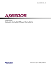
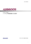
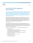
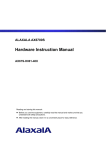
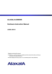
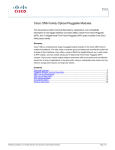
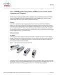
MA-2 AX66S-H001X ALAXALA AX6600S Hardware Instruction Manual Corrections Released July 23, 2010 (Edition 2) 1 MA-2 AX66S-H001X Preface This document contains corrections for the AX6600S Hardware Instruction Manual (Copyright (C) 2009, ALAXALA Networks Corporation. All rights reserved.). If you intend to use the Switch, please read this document carefully. This document applies to the following manual: Item No. 1 Manual Name ALAXALA AX6600S Hardware Instruction Manual Manual Number AX66S-H001X Trademarks - Ethernet is a product name of Xerox Corporation. - Windows is a registered trademark of Microsoft Corporation in the United States and other countries. - Other company and product names are trademarks or registered trademarks of their respective owners. Note The information in this document is subject to change without notice. Edition history July 23, 2010 (Edition 2) Copyright Copyright (C) 2010 ALAXALA Networks Corporation. All rights reserved. Conventions: The terms "Switch" and "switch" The term Switch (upper-case "S") is an abbreviation for any or all of the following models: z AX6600S series switch The term switch (lower-case "s") might refer to a Switch, another type of switch from the current vendor, or a switch from another vendor. The context decides the meaning. 2 MA-2 AX66S-H001X Contents Safety Information..................................................................................................................................... 4 1. Components Overview.......................................................................................................................... 5 2. Preparation for Installation .................................................................................................................... 7 3. Preparation of Interface Cables and Terminals ..................................................................................... 8 4. Installing a Switch ............................................................................................................................... 10 5. Adding and Replacing Optional Modules ............................................................................................ 15 3 MA-2 AX66S-H001X Safety Information The following note has been added after "Avoid looking directly at laser beams.". Addition: Do not touch the SFP-T transceiver during operation or just after operation has stopped. During operation and when a link is being established, the temperature of the SFP-T transceiver can rise to 65oC. Do not touch the SFP-T transceiver while it is operating and just after it has stopped. Doing so could result in burns. Caution: Hot (During operation, all sides are very hot.) When you remove the SFP-T transceiver, use the procedure below. Failure to do so could result in burns. - To remove the SFP-T transceiver while the Switch is on, execute the inactive command, and then wait 5 minutes before removing the SFP-T transceiver. - To remove the SFP-T transceiver while the Switch is off, turn off the Switch, and then wait 5 minutes before removing the SFP-T transceiver. The following label is affixed to the SFP-T transceiver. 4 MA-2 AX66S-H001X 1. Components Overview 1.7 Transceiver 1.7.1 SFP Table 1-18 has been corrected as follows. Correction: Table 1-18 List of SFP transceivers Number Module name Interface Supported network interface unit 1 SFP-SX Gigabit Ethernet 1000BASE-SX 2 SFP-SX2 Gigabit Ethernet 1000BASE-SX2 3 SFP-LX Gigabit Ethernet 1000BASE-LX 4 SFP-LH Gigabit Ethernet 1000BASE-LH 5 SFP-LHB Gigabit Ethernet 1000BASE-LHB 6 SFP-BX1U Gigabit Ethernet 1000BASE-BX10-U#1 7 SFP-BX1D Gigabit Ethernet 1000BASE-BX10-D#1 8 SFP-BX4U Gigabit Ethernet 1000BASE-BX40-U#2 9 SFP-BX4D Gigabit Ethernet 1000BASE-BX40-D#2 10 SFP-T Ethernet 10/100/1000BASE-T NK1G-24S NK1GS-8M NK1G-24S #1: 1000BASE-BX10-U and 1000BASE-BX10-D are used in pairs. #2: 1000BASE-BX40-U and 1000BASE-BX40-D are used in pairs. The caution about laser beams has been corrected as follows. Correction: SFP transceivers except the SFP-T transceiver use laser beams that are colorless and transparent, and invisible to the eye. Never look directly into the optical transceiver. 5 MA-2 AX66S-H001X A description of the SFP-T transceiver has been added as (10). Addition: (10) SFP-T Figure 1-37a External appearance (1) (2) (1) Label: ALAXALA SFP-T Label color: White (2) Lever color: Yellow The SFP-T transceiver is supported by NK1G-24S. 1.7.2 XFP transceivers The explanation in (2) XFP-LR transceivers has been corrected as follows. Correction: (2) XFP-LR Figure 1-39 External appearance x Type-A module x Type-B module (1) (1) (2) (2) (1) Label: ALAXALA XFP-LR (2) Lever color: Blue Two types of XFP-LR transceivers are available: a type-A module and a type-B module. Functionally, these two modules are identical. 6 MA-2 AX66S-H001X 2. Preparation for Installation 2.4 Power supply facility 2.4.1 Power supply facility for 100 V AC Table 2-5 Inrush current has been corrected as follows. Correction: Table 2-5 Inrush current Current (peak value) 30 A 15 A Time 10 ms or less 150 ms or less 2.4.2 Power supply facility for 200 V AC Table 2-9 Inrush current has been corrected as follows. Correction: Table 2-9 Inrush current Current (peak value) 30 A 15 A Time 10 ms or less 150 ms or less 2.4.3 Power supply facility for −48 V DC Table 2-12 Inrush current has been corrected as follows. Correction: Table 2-12 Inrush current Current (peak value) 60 A Time 40 ms or less 7 MA-2 AX66S-H001X 3. Preparation of Interface Cables and Terminals 3.1 List of interface cables Table 3-1 has been corrected as follows. Correction: Table 3-1 Interface cables Port Transceiver Interface Cable 10/100/1000BASE-T -- 10BASE-T UTP cable (Category 3 or higher) port -- 100BASE-TX UTP cable (Category 5 or higher) -- 1000BASE-T UTP cable (Enhanced category 5 or higher) SFP-T 10BASE-T UTP cable (Category 5 or higher) 100BASE-TX UTP cable (Category 5 or higher) 1000BASE-T UTP cable (Enhanced category 5 or higher) 1000BASE-SX Multiple-terminal mode fiber optic cable 1000BASE-X port SFP-SX (core/cladding diameter = 50 μm/125 μm) Connector RJ-45 connector RJ-45 connector LC duplex connector Multiple-terminal mode fiber optic cable (core/cladding diameter = 62.5 μm/125 μm) SFP-SX2 1000BASE-SX2 Multiple-terminal mode fiber optic cable (core/cladding diameter = 50 μm/125 μm) Multiple-terminal mode fiber optic cable (core/cladding diameter = 62.5 μm/125 μm) SFP-LX 1000BASE-LX Multiple-terminal mode fiber optic cable#1 (core/cladding diameter = 50 μm/125 μm) Multiple-terminal mode fiber optic cable#1 (core/cladding diameter = 62.5 μm/125 μm) Single-terminal mode fiber optic cable (core/cladding diameter = 10 μm/125 μm) SFP-LH 1000BASE-LH Single-terminal mode fiber optic cable (core/cladding diameter = 10 μm/125 μm) Single-terminal mode (DSF) fiber optic cable (core/cladding diameter = 8 μm/125 μm) SFP-LHB 1000BASE-LHB Single-terminal mode fiber optic cable (core/cladding diameter = 10 μm/125 μm) Single-terminal mode (DSF) fiber optic cable (core/cladding diameter = 8 μm/125 μm) SFP-BX1U SFP-BX1D 1000BASE-BX10U 1000BASE-BX10D SFP-BX4U 1000BASE-BX40U SFP-BX4D 1000BASE-BX40D 8 Single-terminal mode fiber optic cable (core/cladding diameter = 10 μm/125 μm) LC simplex connector MA-2 AX66S-H001X Port 10GBASE-R port Transceiver XFP-SR Interface 10GBASE-SR Cable Connector Multiple-terminal mode fiber optic cable (core/cladding diameter = 50 μm/125 μm) LC duplex connector Multiple-terminal mode fiber optic cable (core/cladding diameter = 62.5 μm/125 μm) AUX port XFP-LR 10GBASE-LR XFP-ER 10GBASE-ER XFP-ZR 10GBASE-ZR -- RS-232C Single-terminal mode fiber optic cable (core/cladding diameter = 10 μm/125 μm) RS-232C straight-through cable D-SUB 9-pin connector CONSOLE port -- RS-232C RS-232C crossover cable D-SUB 9-pin connector MANAGEMENT -- port 10BASE-T UTP cable (Category 3 or higher) 100BASE-TX UTP cable (Category 5 or higher) RJ-45 connector #1: Some kinds of multiple-terminal mode fiber optics might increase the BER (bit error rate) when used with 1000Baase-LX. In this case, proper communication can be established by using the mode-conditioning patch code. 3.2 Details about interface cables 3.2.1 UTP cables (10/100/1000BASE-T) The SFP-T transceiver's physical specifications have been added as Table 3-2a. Addition: Table 3-2a 10/100/1000BASE-T physical specifications (SFP-T transceiver) Physical specifications Item Category Transmission distance (max.) 10BASE-T 100BASE-TX 1000BASE-T Category 5 and higher Category 5 and higher Enhanced category 5 and higher 100 m 100 m 100 m 9 MA-2 AX66S-H001X 4. Installing a Switch 4.9 Inserting and removing SFP transceivers The explanation about inserting and removing SFP transceivers has been corrected as follows. Correction: SFP transceivers with a network interface unit attached can be inserted and removed while the Switch is on. 4.9.1 Inserting or removing the SFP-SX, SFP-SX2, SFP-LX, SFP-LH, SFP-LHB, SFP-BX1U, SFP-BX1D, SFP-BX4U, or SFP-BX4D (1) Inserting an SFP transceiver Keep the lever upright as shown in the figure, and insert the SFP transceiver until you hear a click. Figure 4-39 Inserting an SFP transceiver (upper port) (3) (1) (2) (1) SFP transceiver (2) Lever (3) Ethernet port The above figure shows an example for inserting an SFP transceiver in the upper Ethernet port of the network interface unit. If you want to insert an SFP transceiver in the lower Ethernet port, turn the SFP transceiver upside down and install it as shown in the figure below. 10 MA-2 AX66S-H001X Figure 4-40 Inserting an SFP transceiver (lower port) (3) (1) (2) (1) Lever (2) SFP transceiver (3) Ethernet port (2) Removing an SFP transceiver Press the lever down in the direction of the arrow. While holding down the lever, pull out the SFP transceiver. Figure 4-41 Removing an SFP transceiver (1) (2) (1) Lever (2) SFP transceiver 11 MA-2 AX66S-H001X 4.9.2 Inserting and removing an SFP-T transceiver During operation and when a link is being established, the temperature of the SFP-T transceiver can rise to 65oC. Do not touch the SFP-T transceiver while it is operating and just after it has stopped. Doing so could result in burns. When you remove the SFP-T transceiver, use the procedure below. Failure to do so could result in burns. - To remove the SFP-T transceiver while the Switch is on, execute the inactive command, and then wait 5 minutes before removing the SFP-T transceiver. - To remove the SFP-T transceiver while the Switch is off, turn off the Switch, and then wait 5 minutes before removing the SFP-T transceiver. For details about the inactive command, see 17. Ethernet in the manual Software Manual Operation Command Reference Vol. 1. (1) Inserting an SFP-T transceiver Keep the lever upright as shown in the figure, and insert the SFP transceiver until you hear a click. Figure 4-41a Inserting an SFP transceiver (upper port) (3) (1) (2) (1) Lever (2) SFP transceiver (3) Ethernet port The above figure shows an example of inserting an SFP transceiver into the upper Ethernet port of the network interface unit. If you want to insert an SFP transceiver in the lower Ethernet port, turn the SFP transceiver upside down and install it as shown in the figure below. 12 MA-2 AX66S-H001X Figure 4-41b Inserting an SFP transceiver (lower port) (3) (1) (2) (1) Lever (2) SFP transceiver (3) Ethernet port (2) Removing an SFP-T transceiver Press the lever down in the direction of the arrow. While holding the lever, pull out the SFP transceiver. Figure 4-41c Removing an SFP transceiver (1) (2) (1) Lever (2) SFP transceiver 13 MA-2 AX66S-H001X 4.12 Connecting interface cables The explanation about connecting a UTP cable has been corrected as follows. Correction: (1) UTP cable Push the connector until you hear a click. Figure 4-46 Connecting a UTP cable (1) (2) (3) (1) UTP cable (2) Tab (3) Ethernet port The above figure shows an example of inserting a UTP cable into the upper Ethernet port of the network interface unit. Use the same procedure to connect a UTP cable to the SFP-T transceiver. To detach the cable, hold the tab down and pull out the connector. 14 MA-2 AX66S-H001X 5. Adding and Replacing Optional Modules 5.5 Adding or replacing a control and switching unit The explanation, notes, and figures in (2) Installing a control and switching unit have been corrected as follows. Correction: (2) Installing a control and switching unit A control and switching unit can be installed while the Switch is on. Note, however, that the procedure varies depending on whether the Switch is on or off. In addition, the procedure also varies depending on whether the installed control and switching unit is the active system or the standby system. Install the unit while referring to the following figure. When replacing both units with the Switch turned off in a dual configuration, first install the active system and restore the operating information (steps 1 to 6-1), and then install the standby system and restore the operating information (steps 1 to 6-2). For details about steps 1 to 6 in the figure, see the description of the steps that follow Figure 5-23 Installation overview. 15 MA-2 AX66S-H001X Figure 5-23 Installation overview Start Step 1: Partially insert the CSU. Step 2: Push the CSU until the levers touch the Switch. Step 3: Close the levers of the CSU. Step 4: Tighten the screws of the CSU. Is the CSU being inserted while the Switch is on? No Turn on the Switch. Yes For details about how to turn on the Switch, see 4.13 Turning on and off the Switch. Step 5: Turn on the CSU. Is the installed CSU the active or standby system? Standby system Active system Step 6: Restore the operation information. Step 6-1 Restore the CSU of the active system. End 16 Step 6-2 Restore the CSU of the standby system. MA-2 AX66S-H001X The description of (2) Installing a control and switching unit (step 6) has been corrected as follows. Correction: Step 6 Restore the operation information. Because the restoration procedure is different for the active system and the standby system, make sure you perform the appropriate procedure. 6-1 Restoring the control and switching unit of the active system 1. Restore the operating information from the file you have backed up. (Use the restore command.) To do this, use the backup file stored on a memory card or an ftp server. If you cannot find the backed up software in the backup file, see the Software Update Guide to install the software, and then execute the restore command. For details about the restore command, see 9. Checking the Software Version and Switch Status in the manual Software Manual Operation Command Reference Vol. 1. BOOT INST OS is displayed on the system operation panel of the control and switching unit if the software is not installed. When the software is installed, BOOT INST OS disappears. 6-2 Restoring the control and switching unit of the standby system 1. Install the software on the control and switching unit of the standby system. (Use the cd command to move to the directory where the update file is stored, and then use the ppupdate command. Initially, the update file is named k.img and is saved in the /usr/var/update directory.) 2. Restart the control and switching unit of the standby system. (Use the reload standby command.) 3. Synchronize the configuration, user account, password, and license key settings of the standby system with the settings of the active system. (Use the synchronize command.) 4. When an optional license is installed, restart the control and switching unit of the standby system in order to apply the license key information. (Use the reload standby command.) If you cannot find the update file in /usr/var/update, see the Software Update Guide to transfer the update file to the Switch, and then execute the ppupdate command. For details about the commands to be used, see the following manuals: cd command: 4. Operating the Configuration and Files in the manual Software Manual Operation Command Reference Vol. 1 ppupdate command: 14. Software Management in the manual Software Manual Operation Command Reference Vol. 1 synchronize command: 10. BCU/CSU/MSU Redundancy in the manual Software Manual Operation Command Reference Vol. 2 reload command: 9. Checking the Software Version and Switch Status in the manual Software Manual Operation Command Reference Vol. 1 BOOT INST OS is displayed on the system operation panel of the control and switching unit if the software is not installed. When the software is installed, BOOT INST OS disappears. 17