1
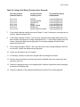
C942 Treadmill
ection Five — Troubleshooting Procedures
Procedure 5.1 — Troubleshooting the Keypad and Upper PCA....................... 5-3
Procedure 5.2 — Troubleshooting the Optional Heart Rate System................ 5-5
Procedure 5.3 — Troubleshooting the Lift System............................................ 5-7
Procedure — Troubleshooting the External A.C. Power Source...................... 5-9
C942 Treadmill
Procedure 5.1 — Troubleshooting the Keypad and Upper PCA
If the function keys on the electronic console are unresponsive, the problem may be either the
upper PCA or keypad. This troubleshooting procedure gives you the information you need to
determine which of these components is malfunctioning.
Procedure
1.
Set the circuit breaker in the “off” position.
WARNING
Before continuing with this procedure, review the Warning and Caution statements listed in
Section One of the Residential Treadmill Service Manual.
2.
Remove the screws that secure the upper display assembly to the upper handrail. Carefully,
pull some excess interconnect cable out from the targa upright. Rotate the display housing,
so that the rear of the upper PCA is facing upward, and set the display housing on the upper
handrail.
3.
Attach the wrist strap to your arm, then connect the ground lead of the wrist strap to the
treadmill frame.
4.
Set the voltmeter to a range that will conveniently read +6 Vdc.
5.
Set the circuit breaker in the “on” position.
6.
Use a DVM, set for DC volts, and read between pin 6 of J2 and the each of the pins in Table
5.1 (no keys pressed) and Table 5.2 (with the appropriate key pressed)...
Table 5.1. Voltage Test Points (Function Keys Not Pressed)
Place the positive lead of the
voltmeter on...
Pin 3 of J4
Pin 4 of J4
Pin 5 of J4
Pin 7 of J4
Pin 8 of J4
Pin 9 of J4
Pin 10 of J4
The voltmeter should
read...
5 Vdc ± 500 mVdc
5 Vdc ± 500 mVdc
5 Vdc ± 500 mVdc
5 Vdc ± 500 mVdc
5 Vdc ± 500 mVdc
5 Vdc ± 500 mVdc
5 Vdc ± 500 mVdc
C942 Treadmill
Table 5.2. Voltage Test Points (Function Keys Pressed)
Place the positive
voltmeter lead on...
At the electronic
console, press...
The voltmeter should
read between...
Pin
Pin
Pin
Pin
Pin
Pin
Pin
ENTER
INCLINE DOWN
INCLINE UP
STOP
SPEED DOWN
SPEED UP
QUICK START/CHANGE
0 Vdc and 500
0 Vdc and 500
0 Vdc and 500
0 Vdc and 500
0 Vdc and 500
0 Vdc and 500
0 Vdc and 500
3 of J4
4 of J4
5 of J4
7 of J4
8 of J4
9 of J4
10 of J4
mVdc
mVdc
mVdc
mVdc
mVdc
mVdc
mVdc
7.
If the voltage readings match those listed inTables 5.1 and 5.2 and one or more keys do not
function, replace the upper PCA.
8.
If the voltage readings in Table 5.1 are incorrect, disconnect the keypad cable from the key
pad connector and repeat the voltage measurements in 5.1. If the voltage readings are now
correct, replace the display housing (keypad). If the voltage readings are still incorrect,
replace the upper PCA.
9.
If the voltage readings in Table 5.1 are correct and one or more voltage readings in Table 5.2
are incorrect, replace the display housing (keypad).
10. Set the circuit breaker in the “off” position.
11. If necessary, carefully re-connect the keypad cable to the keypad connector.
12. Remove the ground lead of the wrist strap from the treadmill frame, then remove the wrist
strap from your arm.
13. Position the display enclosure on the display plate. Install the screws that secure the display
enclosure to the display plate.
14. Check the operation of the treadmill as described in Section Three of this appendix.
C942 Treadmill
Procedure 5.2 — Troubleshooting the Optional Heart Rate
System
Note:
The 9.41S and 9.41Si treadmills are not equipped with heart rate as standard equipment. Heart
rate will be present only if the optional heart rate system has been installed.
If the HEART RATE indicator does not blink with your heart beat when you perform Procedure
2.1, the problem may be either the heart rate receiver assembly or the chest strap assembly. This
troubleshooting procedure gives you the information you need to determine which of these
components is malfunctioning.
Procedure
1.
If you are referring to this procedure because the HEART RATE indicator did not blink
properly when you performed Procedure 2.1...
THEN...
Skip to Step 6.
OTHERWISE...
Continue with the next step.
2.
Plug the power cord into the wall outlet, then turn on the treadmill with the ON/OFF switch.
3.
If necessary use conductive spray (Precor part number 37364-101) to ensure good contact
between the chest strap transmitter and the user, put on the heart rate chest strap
transmitter.Enter the diagnostics program per Procedure 2.1 or 2.2. Proceed to the heart
rate test portion of the diagnostics program. HArt will be displayed in the right display
window when the heart rate routine is accessed.
4.
If the HEART RATE indicator blinks with your heart beat and the heart rate information
displayed is correct...
THEN...
The Heart Rate system is operating
correctly. There is no need to continue
with this procedure.
5.
OTHERWISE...
Continue with the next step.
Re-adjust the fit of the chest strap. If the HEART RATE indicator still does not blink as
described in Step 4. If the chest strap transmitter has a replaceable battery, replace the
battery. If the HEART RATE indicator still does not blink as described in Step 4...
C942 Treadmill
THEN...
Continue with the next step.
6.
Hold the Heart Rate Test Transmitter (Precor part number 20045-101) near the display
housing. If the HEART RATE indicator on the electronic console blinks with the LED on the
Smart Rate Test Generator...
THEN...
The chest strap assembly is bad.
Wear a new chest strap assembly
when you use the Heart Rate
System.
7.
OTHERWISE...
The Heart Rate system is operating
correctly. There is no need to continue
with this procedure.
Press ENTER to return to the User ID.
OTHERWISE...
The heart rate receiver assembly is
bad. Replace the heart rate receiver as
described in Procedure 5.4 of the
Residential Treadmill Service Manual.
C942 Treadmill
Procedure 5.3 — Troubleshooting the Lift System
System Description
The lift system is powered by a 120 Vac lift motor that uses two independent motors windings,
one operates the motor in an upward direction and one operates the motor in a downward
direction. The motor contains a 10 KΩ potentiometer, driven by the motor, that indicates lift
position. AC power to operate the lift motor is provided by a pair of triac. One triac provides power
to the “up” winding of the lift motor and the other triac provides power to the “down” winding of the
lift motor. The triacs are controlled either manually or by software control from the upper PCA.
1.
If the lift motor will not move skip to step 7. If the lift motor moves and an error occurs
continue with step 2.
2.
Access the diagnostics program per Procedure 3.2 and proceed to the lift calibration portion
of the diagnostics program. If the lift calibration number is 0 or 255 skip to step 3. Operate
the lift, if the lift calibration number does not increment as the lift moves, skip to step 3. If the
calibration number increments as the lift moves, recalibrate the lift per Procedure 5.3. If
recalibration does not correct the problem, continue with step 3.
3.
Set the treadmill circuit breaker in the “off” position. Using an ohmmeter, measure between
terminal 4 (white wire) and terminal 6 (orange wire) of the P2 connector on the lower PCA.
The measurement should be approximately 10 KΩ. If the measurement is open (∞) or
significantly high or low, replace the lift motor.
4.
Using an ohmmeter, measure between terminals 4 and 5 of P2 and measure between 5 and
6 of P2 on the lower PCA. The two measurements should total approximately 10 K Ω. If the
measurement is open (∞) or significantly high or low, replace the lift motor.
5.
If you have performed all of the above tests and an error still occurs when the lift motor
operates, there are three parts that could cause the problem. There are not any good tests
to check these parts other than substituting a known good part. They are lower PCA, ribbon
cable and upper PCA. Replace only one part at a time. If the new part does not correct the
problem replace the original part.
6.
If you have performed all of the above tests and the lift system is still not functioning, call
Precor Technical Support.
7.
Set the treadmill circuit breaker in the “off” position. Remove the F2 (2 amp slow blow) fuse
from the lower PCA. Measure the fuse with an ohmmeter. The measurement should be 1Ω
or less. If the fuse is good, re-insert the fuse and skip to step 9. If the fuse is open (∞)or
significantly high, replace the fuse. Before operating the lift motor it is necessary to perform
a continuity test on the lift motor.
C942 Treadmill
8.
Remove the P2 connector from the lower board. Using an ohmmeter, measure between
terminals 1 and 3 of P2, between terminals 1 and 2 of P2 and between terminals 2 and 3 of
P2. The measurements should be approximately 14.5 Ω, 14.5Ω and 29Ω, respectively. If any
of the measurements are significantly low, replace the lift motor.
9.
Re-insert the P2 connector in the lower PCA. Set the treadmill circuit breaker in the “on”
position. Using an AC voltmeter, monitor the voltage between terminals 1 and 2 (red and
white wires) of the P2 connector. Enter the manual program and press the INCLINE ▲ key.
The measurement should be approximately 120 Vac (line voltage). If the voltage is present
and the lift motor moves normally, skip to step 10. The voltage will only be present until such
time as an error occurs. If line voltage is not present skip to step 11. If line voltage is
measured but the motor does not move, replace the lift motor.
10. Monitor terminals 1 and 3 (white and black wires) of P2. Enter the manual program and
press the INCLINE ▼ key. The measurement should be approximately 120 Vac (line
voltage). If the voltage is present and the lift motor moves normally skip to step 12. The
voltage will only be present until such time as an error occurs. If line voltage is measured but
the motor does not move, replace the lift motor.
11.
If line voltage is not present in both steps 9 and 10, there are three parts that could cause
the problem. There are not any good tests to check these parts other than substituting a
known good part. They are lower PCA, ribbon cable and upper PCA. Replace only one part
at a time. If the new part does not correct the problem replace the original part.
12.
If you have performed all of the above tests and the lift system is still not functioning, call
Precor Technical Support.
C942 Treadmill
Procedure 5.6 — Troubleshooting the External A.C. Power
Source
It is extremely important that any Precor treadmill be connected to and operated on a dedicated
20 amp A.C. circuit. A 20 amp dedicated circuit is defined as: a circuit fed by a 20 amp circuit
breaker that feeds a single load. A treadmill operating from a non-dedicated circuit or a circuit
breaker of less than 20 amps capacity will not have the necessary power available to operate
normally under higher load conditions. The lack of available power can cause any number of
symptoms ranging from numerous intermittent (seemingly inexplicable) error conditions, poor
speed control, or tripping the house circuit breaker.
If any of the above symptoms exist the external A.C. circuit must be checked and confirmed to be
a 20 amp dedicated circuit before troubleshooting the treadmill.
In addition the A.C. voltage must be checked. Nominal A.C. operating voltage on 120 Vac circuits
is 105 Vac to 120 Vac. Nominal A.C. operating voltage on 240 Vac circuits is 208 Vac to 240 Vac.
For operator safety considerations and to minimize electrostatic discharge conditions the A.C.
frame ground continuity must also be verified to be a low resistance connection to the A.C.
distribution ground bar.
Important
If the A.C. circuit feeding a treadmill is found to be a non-dedicated circuit or a circuit equipped
with a circuit breaker with a capacity of less than 20 amps, the A.C. circuit must be corrected to
be a 20 amp dedicated circuit before any reliable troubleshooting can be performed on the
treadmill. More importantly, a non-dedicated circuit may constitute a safety hazard to the treadmill
operator.
120 Vac Systems
120 Vac distribution systems utilize a single pole circuit breaker (hot lead) and a neutral lead
connected to a common neutral (ground) bar. The A.C. safety ground (green wire) is connected
to a separate ground bar in the distribution system.
The most common problems found are (1) the circuit is fed by a circuit breaker of less than 20
amp capacity, (2) the circuit breaker correctly feeds a single A.C. outlet but the neutral is common
between several A.C. outlets and (3) both the hot and neutral leads feed several A.C. outlets. The
appropriate correction action or actions (see below) must be followed if any of the above
conditions exist. Corrective actions should only be undertaken by a licensed electrician.
1.
The circuit breaker feeding the treadmill is not a 20 amp circuit breaker.
If the circuit breaker is greater than 20 amps, the circuit breaker should be replaced with a
20 amp circuit breaker. If the circuit breaker is less than 20 amps the circuit breaker must be
replaced with a 20 amp circuit breaker and the wiring from the A.C. distribution must be
capable of safely handing 20 amps. If the A.C. wiring is under sized, it must be replaced with
wire capable of safely handling 20 amps. Please, refer to local electrical codes when
determining the appropriate wire size for a 20 amp circuit.
C942 Treadmill
2.
The circuit breaker correctly feeds a single A.C. outlet but the neutral is common
between several A.C. outlets.
The common neutral lead must be removed from treadmill’s A.C. outlet and a new neutral
lead from the treadmill’s A.C. outlet to the A.C. neutral distribution bar must be added.
3.
Both the hot and neutral leads feed several A.C. outlets.
Both the common neutral and hot leads must be removed from treadmill’s A.C. outlet and a
new neutral lead and hot lead from the treadmill’s A.C. outlet to the A.C. neutral distribution
bar and circuit breaker must be added.
240 Vac Systems
240 Vac distribution systems utilize a double pole circuit breaker (two hot leads) The A.C. safety
ground (green wire) is connected to a ground bar in the distribution system.
The most common problems found are (1) the circuit is fed by a circuit breaker of less than 20
amp capacity and (2) both the hot leads feed several A.C. outlets. The appropriate correction
action or actions (see below) must be followed if any of the above conditions exist. Corrective
actions should only be undertaken by a licensed electrician.
1.
The circuit breaker feeding the treadmill is not a 20 amp circuit breaker.
If the circuit breaker is greater than 20 amps, the circuit breaker should be replaced with a
20 amp circuit breaker. If the circuit breaker is less than 20 amps the circuit breaker must be
replaced with a 20 amp circuit breaker and the wiring from the A.C. distribution must be
capable of safely handing 20 amps. If the A.C. wiring is under sized, it must be replaced with
wire capable of safely handling 20 amps. Please, refer to local electrical codes when
determining the appropriate wire size for a 20 amp circuit.
2.
Both the hot leads feed several A.C. outlets.
Both hot leads must be removed from treadmill’s A.C. outlet and two new hot leads from the
treadmill’s A.C. outlet to the circuit breaker must be added.
A licensed electrician may use the followings hints to determine if an A.C. service is dedicated.
1.
If, on a 120 Vac system, the A.C. distribution panel contains more circuit breakers than
neutral leads, the system has shared neutral leads and is not dedicated.
2.
If an A.C. outlet (120 or 240 Vac) has multiple hot and/or neutral leads, it is not a dedicated.
3.
If either of the above conditions exist, the system is not dedicated. However, absence of the
above conditions does not necessarily mean that the system is dedicated. If any doubt
exists about A.C. systems dedication, point to point tracing of the A.C. wiring may be the
only way to prove system dedication.