1
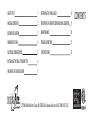
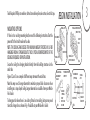
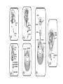
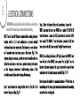
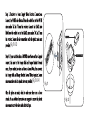
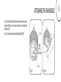
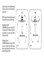
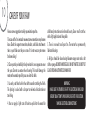
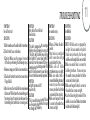
GILERA
This product is protected by United States Federal and/or State Law, including Patent, Trademark and/or Copyright laws.
Manual design and all elements of manual design are protected by U.S. Federal and/or State Law, including Patent, Trademark and/or Copyright Laws.
warranty is for one (1) year from the date of purchase from an authorized Minka-Aire dealer.
This warranty is only valid to the original purchaser or user against all defects in material and workmanship (light bulbs
excluded) for one (1) full year. Additionally, Minka-Aire warrants the motor only for the lifetime of the Minka Aire ceiling
fan (excluding wall controls and electrical components), to the original purchaser or user.
The warranty is voided with the use of any non- Minka-Aire electrical devices, E.g., wall controls or electrical dimmer switches, etc...
The warranty is void once the original purchaser or user ceases to own the fan or the fan is moved from its original point of installation.
The warranty is void with the use of any hanger bracket (non-Minka Aire or non-fan specific) other than the hanger bracket supplied & installed
with this specific fan.
Warranty Service Information
To obtain warranty servic during the warranty period, the purchaser should return the fan with the sales receipt to the original place of
purchase. The authorized Minka-Aire ® dealer, at its sole discretion, will either repair or replace the fan after verifying the legitimacy of the warranty
claim. Replacement is subject to availability of the same model. If the model is unavailable it will be replaced by one of equal value. This is a limited
warranty; the original purchaser or user is responsible for the cost of removal and reinstallation of repaired or replacement product.
To obtain the name of the Minka-Aire ® authorized dealer nearest you call the Minka-Aire® customer care department at 1-800-307-3267, or
contact Minka-Aire ® through www.minkagroup.net and write to: “Ask Mr. Minka” to answer any questions or if you require assistance.
Date Purchased
Store Purchased
Model Number
F733
Serial Number
SAFETY FIRST
1
ATTACHING THE FAN BLADES
8
PACKAGE CONTENTS
2
OPERATING THE REMOTE CONTROL/WALL CONTROL
9
BEGIN INSTALLATION
3
MAINTENANCE
10
HANGING THE FAN
4
TROUBLESHOOTING
11
ELECTRICAL CONNECTIONS
5
SPECIFICATIONS
12
INSTALLING THE WALL TRANSMITTER
6
FINISHING THE INSTALLATION
7
1151W. Bradford Court, Corona CA 92882 For Customer Assistance Call: 1-800-307-3267
CONTENTS
1
SAFETY FIRST
3.
4.
5.
6.
7.
8.
9.
1. Before you begin installing the fan, shut power off at the circuit breaker of the fuse box.
2. Be cautious! Read all instructions and safety information before installing your new fan. Review accompanying assembly diagrams.
Make sure that all electrical connections comply with local codes, ordinances, or National Electrical Codes. Hire a qualified electrician or consult a
do-it-yourself wiring handbook if you are unfamiliar with installing electrical wiring.
Make sure the installation site you choose allows the fan blades to rotate without any obstructions. Allow a minimum clearance of 7 feet from
the floor and 18 inches from the tip of the blades to the wall.
NOTE: THIS CEILING FAN EXCEEDS THE MAXIMUM WEIGHT SPECIFIED BY UL FOR HANGING FROM A STANDARD OUTLET BOX. SPECIAL
REINFORCEMENT OF THE CEILING IS REQUIRED FOR INSTALLATION.
CAUTION: Use the wood screws provided for fan installation. The wood screws must go through the outlet box via the knock outs and secured
directly to the building joist.
After you install the fan, make sure that all mounting components are secured to prevent the fan from falling.
Do not insert anything into the fan blades while the fan is operating.
Turn the fan off and wait for the blades to stop completely before cleaning or performing any maintenance.
NOTE:The important safeguards and instructions appearing in this manual are not meant to cover all possible conditions and situations that may
occur. It must be understood that common sense, caution and care are factors which can not be built into this product. These factors must be
supplied by the person (s) installing, caring for and operating the unit.
NOTE: READ AND SAVE ALL INSTRUCTIONS!
WARNING
SUPPORT DIRECTLY FROM BUILDING STRUCTURE.
TO REDUCE THE RISK OF FIRE, ELECTRIC SHOCK OR OTHER PERSONAL INJURY. MOUNT FAN DIRECTLY TO THE BUILDING JOIST USING THE
WOOD SCREWS AND WASHERS PROVIDED WITH THE FAN. THE WOOD SCREWS MUST GO THROUGH THE OUTLET BOX VIA THE KNOCK
OUTS. CONSULT A QUALIFIED ELECTRICIAN IF IN DOUBT.
TO REDUCE THE RISK OF PERSONAL INJURY, DO NOT BEND THE BLADE HOLDERS WHILE INSTALLING, BALANCING THE BLADES, OR
CLEANING THE FAN. DO NOT INSERT FOREIGN OBJECTS BETWEEN ROTATING FAN BLADES.
TO REDUCE THE RISK OF FIRE OR ELECTRIC SHOCK, DO NOT USE THIS FAN WITH ANY SOLID-STATE SPEED CONTROL DEVICE.
TO REDUCE THE RISK OF FIRE OR ELECTRONIC SHOCK, THIS FAN ONLY CAN USE CFR-3T SOLID-STATE SPEED CONTROL WITH TR111A WALL
CONTROL ONLY.
2
PACKAGE CONTENTS
1. Fan motor/housing ass'y
2. Canopy
3. Fan blade
4. Hanger bracket plate
4a. Mounting hardware:
M6.5x89mm wood screw (3pcs)
M6.5(Ø6.4x11.3x0.4-1.7mm-12
toothes) washer (3 pcs)
Ø6.5x19x1mm flat washer (3 pcs)
M5 nylon nut (3 pcs)
Ø5x14x1mm flat washer (3 pcs)
3/16" (Ø5.2x8.4x1.00mm) spring washer (3 pcs)
5. Hanger bracket
6. Canopy cover
7. Standard 6"downrod assembly
8.
9.
10.
11.
A.
B.
C.
D.
E.
Minimum 3-1/2" length downrod (for close
to ceiling mounting only)
Blade holder
Wall control transmitter include below pcnts
1) big wall plate (2 pcs)
2) small wall plate (2 pcs)
3) screw (6 pcs)
Receiver with wire nuts(10pcs)
Blade Attachment Hardware:
3/16"x10mm screws(10pcs)
Bracket Attachment Hardware:
1/4"-20x13mm screws(7pcs)
Wire Nut (3 pcs.)
L hex wrench
Balance kit
BEGIN INSTALLATION
Tools Required: Phillips screw driver; slotted screw driver;pliers;wire cutters; electrical tape.
MOUNTING OPTIONS
If there isn't an existing mounting box,then read the following instructions.Shut the
power off at the circuit breaker or fuse box.
NOTE: THIS CEILING FAN EXCEEDS THE MAXIMUM WEIGHT SPECIFIED BY UL FOR
HANGING FROM A STANDARD OUTLET BOX. SPECIAL REINFORCEMENT OF THE
CEILING IS REQUIRED FOR INSTALLATION.
Secure the ceiling fan's hanging bracket directly from the building structure via the
outlet box.
Figures 1,2 and 3 are examples of different ways to mount the outlet box.
Note:You may need a longer downrod to maintain proper blade clearance when
installing on a steep,sloped ceiling. Longer downrods are available from your MinkaAire® dealer.
To hang your fan where there is an existing fixture but no ceiling joist,you may need
to install a hanger bar as shown in Fig. 4 (available at your Minka-Aire® dealer).
PARALLEL WOOD BRACE
(MIN. 2" THICK)
CEILING JOIST
CROSS BRACE
OUTLET
BOX
OUTLET BOX
CEILING JOIST
OR CROSS BRACE
CEILING JOIST
Fig.1
ANGLED CEILING
MAXIMUM 27
ANGLE
Fig.3
PROVIDE STRONG
SUPPORT
HANGER
OPENING
MUST
BE FACING
UP-SIDE
HANGER BAR
(OPTIONAL)
OUTLET BOX
Fig.4
Fig.2
CEILING
JOIST
HANGER
BRACKET
3
CANOPY
FLAT
WASHERS
OUTLET
BOX
SPRING
WASHERS
Fig.5
KNOCK
OUT
Fig.7
HEX NUTS
COUPLING
COVER
SCREW
HANGER
BRACKET
HITCH PIN
LOCK PIN
OUTLET
BOX
SET SCREW
SET SCREW
HANGER
BRACKET
PLATE
REGISTRATION
SLOT
STAR WASHERS
LOCK WASHERS
FLAT WASHERS
Fig.6
WOOD SCREWS
Fig.10
Fig.8
Fig.9
5
ELECTRICAL CONNECTIONS
WARNING:To avoid possible electrical shock be sure electricity is
turned off at the main fuse or breaker box before wiring.
3
4
(Fig. 11 & 12)
(Fig. 13 & 14)
Fig. 11
Fig. 12
CONNECT
CONNECT
Fig. 13
Fig. 14
INSTALLING THE WALL TRANSMITTER
WARNING! HOOK UP "IN SERIES" ONLY. DO NOT CONNECT NEUTRAL SUPPLY WIRE OF
ELECTRIC CIRCUIT TO THE TRANSMITTER WALL SWITCH, DAMAGE TO THE TRANSMITTER
WALL SWITCH AND POSSIBLE FIRE COULD OCCUR.
Step 1.Remove the existing wall plate and switch from the wall outlet box.
Step 2.Make the electrical connections as shown in Fig.15. If your outlet box has a ground
wire (Green or Bare Copper) connect the Transmitter's ground wire directly to one of the
screws from the outlet box . Secure all wire connections with the plastic wire nuts provided.
Step 3.Carefully tuck the wire connections inside the outlet box. Use the screws provided to
secure the wall transmitter and wall plate to the outlet box. (Fig. 15)
NOTE: Your Aire Control TM System includes two sets of face and decorative plate color options.
The wall control comes with standard white faceplate attached. If you desire to replace it with
the lvory color faceplate included, use a small flat screw driver and gently pry it apart from the
top or bottom of the plate.
Fig.15
6
7
FINISHING THE INSTALLATION
Step 1. Remove 1 of the 2 screws from the bottom of the hanger bracket and loosen the
other one half a turn from the screw head.
Step 2. Slide the canopy up towards the hanger bracket and place the key hole on the canopy
over the screw on the hanger bracket, turn canopy until it locks in place at the narrow section
of the key holes. (Fig. 16)
Step 3. Align the circular hole on canopy with the remaining hole on the hanger bracket, secure
by tightening the two set screws.
Step 4. Twist the canopy cover to tighten the canopy cover with canopy.
Fig.16
ATTACHING THE FAN BLADES
Step 1. Attach the blade holder onto the motor using the screws
provided. Tighten screws securely. Repeat for remaining blade
holders.(Fig. 17).
Step 2. Attach the fan blade to the blade holders.(Fig. 18)
ring
blade holder
screw
Fig.17
Fig.18
8
Speed settings for warm or cold weather depend
on factors such as room size, ceiling height and
number of fans.
NOTE: To change the direction of the rotation of
the blades the fan must be in operation mode.
Warm Weather (forward)
A DOWNWARD airflow creates a cooling effect
as shown in Figure 19. This allows you to set your
air conditioner on a warmer setting without
affecting your comfort.
Cool Weather (Reverse)
An UPWARD airflow moves warmer air off the
ceiling area as shown in Figure 20.This allows
you to set your heating unit on a cooler setting
without affecting your comfort.
WINTER OPERATION
SUMMER OPERATION
Fig. 19
Fig. 20
10
CARE OF YOUR FAN
Here are some suggestions to help you maintain your fan.
1. Because of the fan's matural novement,some connections may become
loose. Check the support connections,brackets, and blade attachments
twice a year. Make sure they are secure (It is not necessary to remove
fan from ceiling. )
2. Clean your fan periodically to help maintain its new appearance over
the years. Do not use water when cleaning. This could damage the
motor,or the wood,or possibly cause an electrical shock.
3. Use only a soft brush or lint-free cloth to avoid scratching the finish.
The plating is sealed with a lacquer to minimize discoloration or
tarnishing.
4. You can apply a light coat of furniture polish to the wood for
additional protection and enhanced beauty. Cover small scratches
with a light application of shoe polish.
5. There is no need to oil your fan. The motor has permanently
lubricated bearings.
6. All glass should be cleaned using lukewarm soapy water and a soft
cloth or sponge DO NOT IMMERSE GLASS IN HOT WATER DO NOT PUT
GLASS INTO AN AUTOMATIC DISHWASHER.
WARNING
MAKE SURE THE POWER IS OFF AT THE ELECTRICAL PANEL BOX
BEFORE YOU ATTEMPT ANY REPAIRS. REFER TO THE SECTION,
"MAKING ELECTRICAL CONNECTIONS".
TROUBLESHOOTING
SYMPTOM
SYMPTOM
Lights shut off and will not
Fan will not start
come back on.
SOLUTION
SOLUTION
1.Check to make sure the wall switch is turned on. 1. This unit is equipped with a wattage
limiting device Lamping in excess of
2.Check circuit fuses or breakers.
190 watts will disable your ceiling
3.Cantion! Make sure the power is turned fans light kit. To reset your light kit
off before performing the following steps. you must turn the power off and relamp Keeping the wattage under 190
4.Remove canopy and check wire connections. watts. Restore power to your ceiling
5.Check wall control transmitter connections fan and continue normal operation.
SYMPTOM
(if applicable).
Fan/Light turn on and off
6.Note: Fan must be installed from a maximum unexpectedly
distance of 40 feet from the transmitting unit SOLUTION
for proper signal transmission between the 2.This is caused by interference. Please
transmitting unit and the fan's receiving unit. see “Frequency interference” for steps
to change the frequency.
SYMPTOM
Fan sounds noisy
SOLUTION
1. Allow a 24-hour "break in"
period.
Most noises associated
with a new fan will go
away during this time.
2 Make sure all blade
attachment screws are tight.
3Make sure outlet box is
secured to building structure, if
necessary use the wood
screws provided to further
secure outlet box to joist.
4Make sure hanger bracket
is secure to the outlet box,
screws are tight.
11
SYMPTOM
Fan Wobble
SOLUTION
1.NOTE: All blade sets are grouped by
weight. Because wood and plastic
blades vary in density, the fan may
wobble even though blades are matched.
2Make sure outlet box is secured to
building structure, if necessary use
the wood screws provided to further
secure outlet box to joist.
3Make sure hanger bracket is secure to
the outlet box, screws are tight.
4 Use the balancing kit provided if the
wobble is excessive (follow instructions
included with balancing kit)
SYMPTOM
Frequency interference
SOLUTION
1.Turn the power off to your ceiling fan.
2.lease use a small size tool to change the frequency setting on the control system.
3.Return power to the unit Note: After the AC power is on,do not press any other
button on the transmitter before pressing the “Stop” button, doing so will cause the
procedure to fail.
4.Within 60 seconds of turning the Fan’s AC power ON.Press the transmitter’s Stop”
button for 10 seconds.
5.Once the receiver has detected the set frequency, the down light of your fan if
applicable will blink twice. (there is no indication if your fan is not equipped with
a light).
6.The receiver has now learn the frequency which has been selected on the transmitter.
After completing the steps above, you should be able to operate the ceiling fan and
light. If the fan is not responding to the transmitter, please turn the power off to
the receiver, and repeat the process.
English Verison