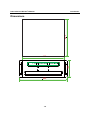
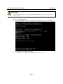
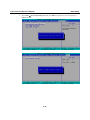
1
DA-710 Series Embedded Computer Hardware User’s Manual First Edition, December 2009 www.moxa.com/product © 2009 Moxa Inc. All rights reserved. Reproduction without permission is prohibited. DA-710 Series Embedded Computer Hardware User’s Manual Any software described in this manual is furnished under a license agreement and may be used only in accordance with the terms of that agreement. Copyright Notice Copyright © 2009 Moxa Inc. All rights reserved. Reproduction without permission is prohibited. Trademarks MOXA is a registered trademark of Moxa Inc. All other trademarks or registered marks in this manual belong to their respective manufacturers. Disclaimer Information in this document is subject to change without notice and does not represent a commitment on the part of Moxa. Moxa provides this document “as is,” without warranty of any kind, either expressed or implied, including, but not limited to, its particular purpose. Moxa reserves the right to make improvements and/or changes to this manual, or to the products and/or the programs described in this manual, at any time. Information provided in this manual is intended to be accurate and reliable. However, Moxa assumes no responsibility for its use, or for any infringements on the rights of third parties that may result from its use. This product might include unintentional technical or typographical errors. Changes are periodically made to the information herein to correct such errors, and these changes are incorporated into new editions of the publication. Technical Support Contact Information www.moxa.com/support Moxa Americas: Toll-free: 1-888-669-2872 Tel: +1-714-528-6777 Fax: +1-714-528-6778 Moxa China (Shanghai office): Toll-free: 800-820-5036 Tel: +86-21-5258-9955 Fax: +86-10-6872-3958 Moxa Europe: Tel: +49-89-3 70 03 99-0 Fax: +49-89-3 70 03 99-99 Moxa Asia-Pacific: Tel: +886-2-8919-1230 Fax: +886-2-8919-1231 Table of Contents Chapter 1 Introduction ..................................................................................................1-1 Overview.................................................................................................................................. 1-2 Model Descriptions and Package Checklist............................................................................. 1-2 Appearance .............................................................................................................................. 1-3 Dimensions .............................................................................................................................. 1-4 Features.................................................................................................................................... 1-5 Hardware Block Diagram ........................................................................................................ 1-6 Hardware Specifications .......................................................................................................... 1-7 Chapter 2 Hardware Installation...................................................................................2-1 Placement Options ................................................................................................................... 2-2 Desktop....................................................................................................................... 2-2 Rack mounting ........................................................................................................... 2-2 Wiring Requirements ............................................................................................................... 2-5 Connecting the Power .............................................................................................................. 2-6 Wiring the Power Inputs .......................................................................................................... 2-7 Power Input Wiring Description .............................................................................................. 2-8 Reset Button........................................................................................................................... 2-10 Front Panel LED .....................................................................................................................2-11 Connecting to a Display......................................................................................................... 2-12 Connecting a PS/2 Keyboard and Mouse............................................................................... 2-13 Connecting to a Serial Device................................................................................................ 2-14 DI/DO .................................................................................................................................... 2-15 Connecting USB Devices ...................................................................................................... 2-16 Gigabit LAN Ports ................................................................................................................. 2-16 Upgrading the Memory Module ............................................................................................ 2-17 Installing a CompactFlash Card............................................................................................. 2-18 Installing a SATA Hard Disk.................................................................................................. 2-20 Inserting and Removing Expansion Modules ........................................................................ 2-22 Chapter 3 BIOS Setup ...................................................................................................3-1 Entering the BIOS Setup Utility .............................................................................................. 3-2 Modifying the BIOS Main Settings ......................................................................................... 3-3 Basic Configuration.................................................................................................... 3-3 System Security.......................................................................................................... 3-3 Advanced Settings ................................................................................................................... 3-4 Hard Disk Boot Priority.............................................................................................. 3-4 Advanced BIOS Features ........................................................................................... 3-5 Quick Power on Self Test........................................................................................... 3-5 Advanced Chipset Settings......................................................................................... 3-6 PnP/PCI Configurations ............................................................................................. 3-7 Peripherals ............................................................................................................................... 3-8 OnChip IDE Device ................................................................................................... 3-8 Onboard Device.......................................................................................................... 3-9 SuperIO Device ........................................................................................................ 3-10 Power ......................................................................................................................................3-11 Hardware Monitor.................................................................................................................. 3-13 Load Defaults......................................................................................................................... 3-14 Exiting the BIOS Setup.......................................................................................................... 3-15 Upgrading the BIOS .............................................................................................................. 3-16 Appendix A Safe Installation Guidelines ....................................................................... A-1 1 Chapter 1 Introduction Thank you for purchasing a Moxa DA-710 Series x86-based industrial ready-to-run embedded computer. DA-710 computers come pre-installed with one of two embedded operating systems: • • DA-710-LX: Linux DA-710-XPE: Windows Embedded Standard 2009 This manual introduces the hardware installation, connector interfaces and BIOS setup of the DA-710. For software configuration and management, please refer to your operating system’s user manual. This chapter covers the following topics: Overview Model Descriptions and Package Checklist Appearance Dimensions Features Hardware Block Diagram Hardware Specifications DA-710 Series HW User’s Manual Introduction Overview The DA-710 computer is based on the Intel x86 processor, supports VGA, and comes with 4 Ethernet ports, 2 RS-232 serial ports, CompactFlash, and USB. The DA-710 comes in a standard 19-inch, 4U high form factor, making it an ideal platform for industrial applications. The DA-710 comes with 4 PCI slots for inserting expansion modules. Moxa provides a variety of communication modules, including an 8-port RS-232/422/485 module, a 4-port 10/100 Mbps LAN module, an 8-port RS-422/485 module, an 8-port switch module, and a universal PCI expansion module. This friendly modular design gives users the advantage of being able to swap out modules quickly and easily. The DA-710 runs Linux or Windows Embedded Standard 2009 (pre-installed), providing a friendly environment for developing sophisticated application software. Moxa provides extensive software support to help programmers easily develop bug-free code quickly and at a lower cost. Model Descriptions and Package Checklist The DA-710 Series includes the following models: y DA-710-LX x86-based rackmount embedded computer with 2 RS-232 ports, 4 LANs, 4 PCI slots, 4 DIs, 4 DOs, VGA, CompactFlash, USB, Linux 2.6 y DA-710-XPE x86-based rackmount embedded computer with 2 RS-232 ports, 4 LANs, 4 PCI slots, 4 DIs, 4 DOs, VGA, CompactFlash, USB, Windows Embedded Standard 2009 Each model is shipped with following standard items: y Quick Installation Guide y Document & Software CD or DVD y Ethernet Cable: RJ45 to RJ45 cross-over cable, 100 cm y Product Warranty Statement Optional Expansion Modules: DA-SP08-I-DB: 8-port RS-232/422/485 serial port module with isolation protection, DB9 connectors. DA-SP08-DB: 8-port RS-232/422/485 serial port module, DB9 connectors. DA-SP08-I-TB: 8-port RS-232/422/485 serial port module with isolation protection, terminal block connectors. DA-SP38-I-TB: 8-port RS-422/485 serial port module with isolation protection, terminal block connectors. DA-SW08-RJ: 8-port 10/100 Mbps unmanaged switch module. DA-LN04-RJ: 4-port 10/100 Mbps LAN module. DA-UPCI-DK: 5V standard PCI extension kit. 1-2 DA-710 Series HW User’s Manual Introduction Appearance Front View Programmable LED x 4 Power/Storage LED Indicators Ethernet LED x 4 Power 1/2 Fail LED Indicators Module A Module B LED x 16 LED x 16 Module C Module D LED x 16 LED x 16 Rackmount Ear Rackmount Ear Rear View Module Slot A VGA PS/2 Module Slot B Module Slot C RS-232 DI x 4 Serial Port x 2 DO x 4 USB 2.0 Host x 4 Expansion modules can be installed in slot A, B, C, or D. 1-3 Power Input 2 Reset Button 10/100/1000 Ethernet Port x 4 ATTENTION Module Slot D Power Input 1 Power Switch DA-710 Series HW User’s Manual Introduction 400 Dimensions 180 420 480 1-4 DA-710 Series HW User’s Manual Introduction Features • Intel Celeron M 2.0 GHz processor with 533 MHz FSB • 1 x 200-pin DDR2 SODIMM socket, supporting up to 2 GB of DDR2 533 RAM. • 4 PCI slots for expansion cards • Quad 10/100/1000 Mbps Ethernet for network redundancy • 1 CompactFlash socket, 1 EIDE connector for DOM or IED hard disk, and 2 serial ATA-150 connectors for storage expansion • 4 USB 2.0 ports for high speed peripherals • 4 DIs and 4 DOs • 2 RS-232 serial ports, supporting non-standard baudrates • LED indicators for displaying dual power, system ready, storage and module statuses • 4 programmable LED indicators for customized functions • Ready-to-run Linux or Windows Embedded Standard 2009 platform • 19-inch rackmount model, 4U high • Fanless design • Dual 100/240 VAC/VDC power input 1-5 DA-710 Series HW User’s Manual Introduction Hardware Block Diagram Power Intel Celeron M 2.0 GHz CPU VGA Intel GMCH GLE960 DDR2 SO-DIMM DOM BIOS CF Socket USB1 LAN Controller USB2 LAN Controller Intel ICH8M USB3 LAN Controller USB4 LAN Controller RTC PCI Slot 1 SATA HDD 1 PCI Slot 2 WDT SATA HDD 2 Gigabit LAN 1 Gigabit LAN 2 Gigabit LAN 3 Gigabit LAN 4 PCI Slot 3 Super I/O PCI Slot 4 Serial Port 1 Serial Port 2 RS-232 x 2 Digital Input Digital Output DI x 4 DO x 4 1-6 KB/MS DA-710 Series HW User’s Manual Introduction Hardware Specifications Computer CPU: OS (pre-installed): System Chipset: BIOS: FSB: System Memory: USB: Storage Built-in: Storage Expansion: HDD Support: Other Peripherals KB/MS: Intel Celeron M 2.0 GHz processor Windows Embedded Standard 2009, Linux 2.6 Intel GLE960 + ICH8M 8 Mbit SPI Serial Flash, PCI Plug & Play, ACPI function support 533 MHz 1 x 200-pin DDR2 SODIMM socket supporting DDR2 533; up to 2 GB max. (1 GB built-in) 4 x USB 2.0 compliant hosts, Type A connector 1 GB for Linux, 2 GB for XPe DOM onboard to store OS via IDE interface CompactFlash socket 2 x SATA connector, 1 x EIDE (UDMA33) connector 1 PS/2 interface, supports standard PS/2 keyboard and PS/2 mouse Display Graphics Controller: Integrated Intel graphics media accelerator (GMA X3100) Display Memory: Dynamic video memory technology Intel Clear Video Technology: MPEG-2 hardware accelerator, Microsoft DirectX 9 Display Interface: CRT interface for VGA output (DB15 female connector) Resolution: QXGA maximum with resolution up to 2048 x 1536 at 60 Hz Ethernet Interface LAN: 4 auto-sensing 10/100/1000 Mbps ports (RJ45) Magnetic Isolation Protection: 1.5 KV built-in Serial Interface Serial Standards: 2 RS-232 ports (DB9 male) ESD Protection: 4 KV for all signals Serial Communication Parameters Data Bits: 5, 6, 7, 8 Stop Bits: 1, 1.5, 2 Parity: None, Even, Odd, Space, Mark Flow Control: XON/XOFF Baudrate: 50 bps to 115.2 Kbps Serial Signals RS-232: TxD, RxD, DTR, DSR, RTS, CTS, DCD, GND Digital Input Input Channels: 4, source type Input Voltage: 0 to 30 VDC 1-7 DA-710 Series HW User’s Manual Introduction Digital Input Levels for Dry Contacts: ‧ Logic level 0: Close to GND ‧ Logic level 1: Open Digital Input Levels for Wet Contacts: ‧ Logic level 0: +3V max. ‧ Logic level 1: +10V to +30V (DI Source to DI) Connector Type Isolation: Digital Output Output Channels: Output Current: On-state Voltage: Connector Type: Isolation LEDs System: LAN: Power Failure: Programmable: Module: 10-Pin Screw Terminal Block (4 points / DI Source / GND) 4 KV optical isolation Physical Characteristics Housing: Weight: Dimensions: Mounting: Environmental Operating Temperature: Operating Humidity: Storage Temperature: Power Requirements Input Voltage: Power Consumption: Regulatory Approvals EMC: Safety: Green Product: Alert Tools: Automatic Reboot Trigger: 4, sink type Max. 200 mA per channel 24 VDC nominal, open collector to 30 V 10-pin screw terminal block (4 points, GND) 4 KV optical isolation Power x 1, Storage x 1 100M x 4, 1000M x 4 LED x 2 LED x 4 Module A x 16, Module B x 16, Module C x 16, Module D x 16 SECC sheet metal (1.2 mm) 14 kg • 400 x 420 x 180 mm (without rackmount ears) • 400 x 480 x 180 mm (with rackmount ears) Standard 19-inch rackmount -10 to 50°C (14 to 122°F) 5 to 95% RH -20 to 80°C (4 to 176°F) Single or dual inputs, 100 to 240 VAC/VDC auto-ranging, 47 to 63 Hz, terminal block 60 W CE, FCC (Part 15 Subpart B, CISPR 22 Class ), CCC UL/cUL, LVD, CCC RoHS, CRoHS, WEEE Built-in buzzer and RTC (real-time clock) with backup lithium battery Built-in WDT (watchdog timer) supporting 1-255 time interval levels for system reset, software programmable Warranty Warranty Period: 3 years Details: See www.moxa.com/warranty 1-8 DA-710 Series HW User’s Manual Introduction 1-9 2 Chapter 2 Hardware Installation The DA-710 Series of embedded computers are compact and rugged, making them suitable for industrial applications. The LED indicators allow users to monitor performance and identify trouble spots quickly, and multiple ports are provided for connecting a variety of different devices. The DA-710 embedded computers come with a reliable and stable hardware platform that lets you devote the bulk of your time to application development. This chapter describes hardware installation and connector interfaces of the DA-710 embedded computers. This chapter covers the following topics: Placement Options ¾ Desktop ¾ Rack mounting Wiring Requirements Connecting the Power Wiring the Power Inputs Power Input Wiring Description Reset Button Front Panel LED Connecting to a Display Connecting a PS/2 Keyboard and Mouse Connecting to a Serial Device DI/DO Connecting USB Devices Gigabit LAN Ports Upgrading the Memory Module Installing a CompactFlash Card Installing a SATA Hard Disk Inserting and Removing Expansion Modules DA-710 Series HW User’s Manual Hardware Installation Placement Options Desktop Place your DA-710 on a clean, flat, well-ventilated desktop. For better ventilation, leave some space between the DA-710 and other equipment. Do not place equipment or objects on top of the DA-710, as this might damage the computer’s internal components. Rack mounting The DA-710 has rackmount supports for installing the embedded computer on a standard rack. ATTENTIONS 1. For maximum safety, at least two persons should work together to lift, place, and attach the embedded computer to the rack. 2. Before you lift or move the embedded computer, make sure that the embedded computer is turned off and power to the rack system is turned off. Four rackmount screws are required to attach the DA-710 to a standard rack. Rackmount Screws Rackmount Screws 2-2 DA-710 Series HW User’s Manual Hardware Installation Follow these steps to install the DA-710 on a rack. Step 1: Reviewing your components. Take the rackmount supports out of their packages. There are two packages, each of which contains 1 rackmount support, 1 rackmount hanger, 2 FMSM5X10 screws, and 8 FMSM4X6 screws. Step 2: Attaching the rackmount hanger to the support. Use 2 FMSM5X10 screws to attach the rackmount hanger to the ear of the rackmount support. Repeat this procedure for the second support and hanger. 2-3 DA-710 Series HW User’s Manual Hardware Installation Step 3: Attaching the rackmount support to the DA-710. Use 8 FMSM4X6 screws to attach one rackmount support to one side of the DA-710. Repeat this procedure for the second support and hanger. Step 4: Installing the DA-710 to a rack. Gently slide the DA-710 onto the rack, and then use screws provided by the rack supplier to fix the rackmount support to the rail. Note that four screws are required to attach the DA-710 to the rack. Use two screws on each side. 2-4 DA-710 Series HW User’s Manual Hardware Installation As a final check, make sure that the four screws are firmly attached to the rack. screws screws Wiring Requirements The following common safety precautions should be observed before installing any electronic device: y Use separate paths to route wiring for power and devices. If power wiring and device wiring paths must cross, make sure the wires are perpendicular at the intersection point. y You can use the type of signal transmitted through a wire to determine which wires should be kept separate. The rule of thumb is that wiring that shares similar electrical characteristics can be bundled together. y Keep input wiring and output wiring separate. y When necessary, it is strongly advised that you label wiring to all devices in the system. ATTENTION Do not run signal or communication wiring and power wiring in the same wire conduit. To avoid interference, wires with different signal characteristics should be routed separately. ATTENTION Safety First! Be sure to disconnect the power cord before installing and/or wiring your device. Electrical Current Caution! Calculate the maximum possible current in each power wire and common wire. Observe all electrical codes dictating the maximum current allowable for each wire size. If the current goes above the maximum ratings, the wiring could overheat, causing serious damage to your equipment. Temperature Caution! Be careful when handling the unit. When the unit is plugged in, the internal components generate heat, and consequently the outer casing may feel hot to the touch. 2-5 DA-710 Series HW User’s Manual Hardware Installation Connecting the Power To power on the DA-710 embedded computer, connect the power line to the DA-710’s AC power connector (located on the right side of the rear panel) using the power cord and then press the power button. The DA-710 offers dual power inputs for redundancy. See the following figure for detailed power cable wiring. PWR 1 PWR 2 +L NC N NC Power 1 +L N Power 2 Surge Ground Chasis Ground +L +L N N Chasis Ground Surge Ground Power Input 2 Power Input 1 Power Switch If the power is being properly supplied, the Power LED will light up first, and then the Storage LED will start blinking when the Flash Disk Module is accessed during boot up. It takes about 30 to 60 seconds for the operating system to boot up. If Power 1 or Power 2 is not functioning, the Power 1/2 Fail LED will light up. If this happens, check the power inputs. Power/Storage LED Indicators Power 1/2 Fail LED Indicators 2-6 DA-710 Series HW User’s Manual Hardware Installation Wiring the Power Inputs See the following figures for how to wire power inputs PWR 1 PWR 2 +L NC N NC Power 1 Surge Ground +L N Power 2 Chasis Ground +L +L N N Chasis Ground Surge Ground AC Terminal Protection earth (Green & Yellow) Line (Black) Neutral (White) Bond Earth (Green) DC Terminal Protection earth (Green & Yellow) DC + (White) DC (Black) 2-7 DA-710 Series HW User’s Manual Hardware Installation Power Input Wiring Description Refer to the following section for detailed power input wiring descriptions. Terminal Number 1 2 3 4 5 6 7 8 Description Note PWR1 Line / DC + is connected to the positive (+) terminal if the power source is DC and to the Line terminal if the power source is AC. PWR1 Neutral / DC - is connected to the negative (-) PWR1 Neutral / DC - terminal if the power source is DC and to the Neutral terminal if the power source is AC. PWR1 Surge Ground is connected to the Chassis Ground terminal via a jumper on the terminal block. Surge Ground is used as the ground conductor for all surge and transient PWR1 Surge Ground suppression circuitry. NOTE: Surge Ground must be disconnected from Chassis Ground during HIPOT (dielectric strength) testing. Chassis Ground is connected to the Safety Ground terminal for AC inputs or the equipment ground bus for DC inputs. Chassis Ground Chassis ground connects to both power supply surge grounds via a removable jumper. No function NC No function NC PWR1 Line/ DC + Chassis Ground is connected to the Safety Ground terminal for AC inputs or the equipment ground bus for DC inputs. Chassis Ground Chassis ground connects to both power supply surge grounds via a removable jumper. PWR2 Surge Ground is connected to the Chassis Ground terminal via a jumper on the terminal block. Surge Ground is PWR2 Surge Ground used as the ground conductor for all surge and transient suppression circuitry. NOTE: Surge Ground must be disconnected from Chassis Ground during HIPOT 2-8 DA-710 Series HW User’s Manual Hardware Installation (dielectric strength) testing. 9 10 PWR2 Line / DC + is connected to the positive (+) terminal if the power source is DC and to the Line terminal if the power source is AC. PWR2 Neutral / DC - is connected to the negative (-) PWR2 Neutral / DC - terminal if the power source is DC and to the Neutral terminal if the power source is AC. PWR2 Line/ DC + For AC Power Input 1. PWR1 Line/ DC + should be connected to AC (Line). 2. PWR1 Neutral / DC -should be connected to AC (Neutral). 3. Surge Ground is connected to the Chassis Ground via a braided cable or other appropriate grounding wire. Surge Ground is used as the ground conductor for all surge and transient suppression circuitry internal to the computer unit. 4. Chassis Ground should be connected to the AC Ground terminal. ATTENTION 1. Equipment must be installed according to the applicable national wiring codes. 2. Surge Ground MUST be disconnected from the Chassis Ground during HIPOT (dielectric strength) testing. 3. All line-to-ground transient energy is shunted to the Surge Ground terminal. If you need to isolate the inputs from the ground, remove the ground braid between Surge and Chassis Ground. Note that all line-to-ground transient protection circuitry will be disabled. For DC Power Input The DA-710 series low voltage DC power supply features reverse polarity protection and dual independent inputs. The dual power inputs allow the connection of two DC sources with the same nominal voltage to provide redundant power supply inputs. The DC source must be connected to the DC inputs according to the polarity markings on the unit. ATTENTION 1. Equipment must be installed according to the applicable national wiring codes. 2. Surge Ground should be connected to Chassis Ground via a braided cable or other appropriate ground wire. 3. Chassis Ground must be connected to a grounded surface or object. 4. All line-to-ground transient energy is shunted to the Surge Ground terminal. If you need to isolate the inputs from the ground, remove the ground braid between Surge and Chassis Ground. Note that all line-to-ground transient protection circuitry will be disabled. 2-9 DA-710 Series HW User’s Manual Hardware Installation HIPOT (Dielectric Strength) Testing Before performing the HIPOT test, you MUST have the jumpers removed and the braided ground cable disconnected. This is required to prevent the transient/surge suppression circuitry, which is connected to Surge Ground, from being activated during the HIPOT test. Reset Button Pressing the Reset button initiates a hardware warm reboot. This button is comparable to a desktop PC’s reset button. After pressing the reset button, the system will reboot automatically. During normal use, you should NOT use the Reset Button. You should only use this button if the software is not working properly. To protect the integrity of data being transmitted or processed, you should always reset the system from the operating system with the software reboot function. Reset Button 2-10 DA-710 Series HW User’s Manual Hardware Installation Front Panel LED There are 76 LED indicators on the front panel. Information about each LED is given in the following table. Programmable LED x 4 Power/Storage LED Indicators LED Power Storage Gigabit LAN LEDs 1-4 Ethernet LED x 4 Power 1/2 Fail LED Indicators Color Green Off Orange/Blinking Off Green Orange Off Green Module A/B/C/D 1-8 Orange Power Fail 1-2 Programmable LEDs 1-4 Module A Module B LED x 16 LED x 16 Off Red Off Orange Off Module C Module D LED x 16 LED x 16 Description Power is on. No power input or power error. Data is being written to or to read from the storage unit. The storage unit is idle. 100 Mbps Ethernet mode. 1000 Mbps (Gigabit) Ethernet mode. No activity or 10 Mbps Ethernet mode. Serial port’s Tx signal, or 100 Mbps Ethernet mode is active. Serial port’s Rx signal, or 10 Mbps Ethernet mode is active. No activity. Power input 1 or 2 has failed. Power inputs are normal. Customer defined. Customer defined. 2-11 DA-710 Series HW User’s Manual Hardware Installation Connecting to a Display Your DA-710 embedded computer comes with a D-Sub 15-pin female connector to connect to a VGA monitor. Be sure to disconnect the power before you connect or disconnect the monitor cable. VGA 5 1 10 6 15 11 Pin No. 1 2 3 4 5 6 7 8 9 10 11 12 13 14 15 2-12 Signal Definition RED GREEN BLUE --GND CRT_DETECT# GND GND +5V GND --DDC_DATA HSYNC VSYNC --- DA-710 Series HW User’s Manual Hardware Installation Connecting a PS/2 Keyboard and Mouse Your DA-710 embedded computer comes with a PS/2 mini-DIN connector to connect to a PS/2 keyboard and PS/2 mouse. This 6-pin mini-DIN connector has the pin assignments shown below. PS/2 Pin No. 1 2 3 4 5 6 Signal Definition PS/2 Keyboard Data PS/2 Mouse Data GND VCC PS/2 Keyboard Clock PS/2 Mouse Clock Use a Y-type cable to convert the mini-DIN connector into two 6-pin mini-DIN connectors in order to simultaneously connect both a PS/2 keyboard and PS/2 mouse. Please note that without the Y-type cable, the PS/2 connector on the DA-710 series can only work with a PS/2 keyboard. A PS/2 mouse will not function when directly connected to the PS/2 connector on the DA-710 series. 2-13 DA-710 Series HW User’s Manual Hardware Installation Connecting to a Serial Device Use a serial cable to plug your serial device into the serial port on the rear panel of the embedded computer. RS-232 Serial Port x 2 The DA-710 offers two serial ports with DB9 male connectors. The pin assignments are shown in the following table: Pin 1 2 3 4 5 6 7 8 1 2 3 4 5 6 7 8 9 2-14 RS-232 DCD RxD TxD DTR GND DSR RTS CTS DA-710 Series HW User’s Manual Hardware Installation DI/DO The DA-710 comes with a 4-ch digital input and a 4-ch digital output through terminal block which is located on the rear panel. DI x 4 DO x 4 To wire these digital inputs and outputs, refer to the following figures: Digital Input Wiring Dry Contact Wet Contact Note: If you are using wet contacts, you must connect “DI Source” to power. Digital Output Wiring 2-15 DA-710 Series HW User’s Manual Hardware Installation Connecting USB Devices The DA-710 embedded computer has four USB 2.0 ports on the rear panel. All of the ports are UHCI, Rev 2.0 compliant and support Plug & Play and hot swapping. These ports can be used to connect USB devices, such as a keyboard, mouse, USB flash disk, and USB CD-ROM. In addition, both USB ports support system boot up, which can be activated by modifying the BIOS settings. The chapter “BIOS Setup” describes the configuration process in detail. USB 2.0 Host x 4 Gigabit LAN Ports The DA-710 has 4 Gigabit LAN ports. When the cable is properly connected, the LEDs on the RJ45 connectors will glow to indicate a proper connection. 10/100/1000 Ethernet Port x 4 8 1 1 8 Pin 1 2 3 4 5 6 7 8 10/100 Mbps ETx+ ETxERx+ ----ERx----- 2-16 1000 Mbps TRD(0)+ TRD(0)TRD(1)+ TRD(2)+ TRD(2)TRD(1)TRD(3)+ TRD(3)- DA-710 Series HW User’s Manual LED Gigabit RJ45 Connector Color Green Orange Off Hardware Installation Description 100 Mbps Ethernet mode 1000 Mbps (Gigabit) Ethernet mode Not operating or 10 Mbps Ethernet mode The default IP addresses and netmasks of the Gigabit LAN ports are as follows: LAN 1 LAN 2 LAN 3 LAN 4 Default IP Address 192.168.3.127 192.168.4.127 192.168.5.127 192.168.6.127 Netmask 255.255.255.0 255.255.255.0 255.255.255.0 255.255.255.0 Upgrading the Memory Module The DA-710 embedded computer supports one 200-pin DDR2 533 SODIMM module, of up to 2 GB. A 1-GB DDR2 SDRAM memory module is factory-installed. To upgrade the DDR2 SDRAM memory module, follow these instructions: 1. Disconnect the DA-710 from the power source. Make sure all the expansion modules have been removed. 2. The DA-710’s memory module is located inside the DA-710, just below the expansion modules. Unscrew the top cover of the DA-710. 2-17 DA-710 Series HW User’s Manual Hardware Installation 3. There are two clutches on both sides of the module. Click the clutches, and the memory module will pop up. Gently remove the module. 4. Carefully slide the module into the clutch at an angle, and then push downward. Make sure the module has been firmly inserted and is oriented correctly. Installing a CompactFlash Card The DA-710 embedded computer comes with a CompactFlash socket. To insert a CompactFlash card, follow these instructions. 1. Disconnect the DA-710 from its power source. 2. Unscrew the cover of the DA-710. The CompactFlash socket is located in the middle of the main board, just below the DOM socket. See the following figure for details. 2-18 DA-710 Series HW User’s Manual Hardware Installation 3. Insert the CompactFlash card into the socket, and then push upward. 4. Make sure the CompactFlash card has been firmly inserted. ATTENTION Make sure you orient the CompactFlash card in the right direction. ATTENTION The DA-710 embedded computer does not support the CompactFlash hot swap and PnP (Plug and Play) functions. You must disconnect the power source before inserting or removing the CompactFlash card. 2-19 DA-710 Series HW User’s Manual Hardware Installation Installing a SATA Hard Disk The DA-710 embedded computer has two SATA connectors for installing two SATA hard disks. To install a 2.5-inch SATA hard disk, follow these instructions. 1. Disconnect the DA-710 from its power source. 2. Open the top cover of the DA-710. A hard disk bracket is located on the left side of the DA-710. 3. Remove the four screws on each corner and remove the hard disk bracket. 2-20 DA-710 Series HW User’s Manual Hardware Installation 4. Install the SATA hard disk in the hard disk bracket. One bracket can hold up to 2 hard disks; you may use either the upper or lower layer on the bracket to install the hard disk. Fasten the two screws on each side of the bracket. Next, install the SATA hard disk and hard disk bracket back into the DA-710.Connect the SATA disk cable and power cable to the SATA hard disk. The DA-710 also offers an IDE connector that can be used to connect to an IDE-based hard disk. However, the IDE connector is being occupied by the DOM. To install an IDE hard disk, remove the DOM first, and then install the hard disk. When finished, connect the disk cable to the IDE connector. Note: The DA-710 computer has been pre-installed with a ready-to-run operating system (either Linux or Windows Embedded Standard 2009) in the DOM. If the DOM has been removed, you must install the operating system in another hard disk. 2-21 DA-710 Series HW User’s Manual Hardware Installation ATTENTION A SATA hard disk cable and SATA power cable and hard disk bracket and the HD bracket are not included in the basic package of the DA-710 embedded computer. Any standard SATA disk and power cable can be used. Inserting and Removing Expansion Modules The DA-710 embedded computer has four expansion slots for inserting expansion modules. Expansion modules can be installed in Slot A, B, C, or D. To insert or remove expansion modules, follow these instructions. 1. Disconnect the DA-710 from the power source. 2. Unscrew expansion module A, B, C or D on the rear panel. 3. Carefully insert or remove the expansion module by pushing or pulling on the two screws at the same time. By pushing or pulling on the two screws evenly, you can ensure that the board is inserted or removed without being damaged. 2-22 3 Chapter 3 BIOS Setup This chapter describes the BIOS settings of the DA-710 embedded computers. The BIOS is a set of input/output control routines for peripherals. The BIOS is used to initialize basic peripherals and helps boot the operating system before the operating system is loaded. The BIOS setup allows the user to modify the system configuration of these basic input/output peripherals. The configuration is stored in the battery-powered CMOS RAM, which retains the system information after system reboots or the power is disconnected. This chapter covers the following topics: Entering the BIOS Setup Utility Modifying the BIOS Main Settings ¾ Basic Configuration ¾ System Security Advanced Settings ¾ Hard Disk Boot Priority ¾ Advanced BIOS Features ¾ Advanced Chipset Settings ¾ PnP/PCI Configurations Peripherals ¾ OnChip IDE Device ¾ Onboard Device Power Hardware Monitor Load Defaults Exiting the BIOS Setup Upgrading the BIOS DA-710 Series HW User’s Manual BIOS Setup Entering the BIOS Setup Utility To enter the BIOS setup utility, press the “Del” key while the system is booting up. The main BIOS Setup screen will appear. A basic description of each function key is listed at the bottom of the screen. Refer to these descriptions to learn how to scroll about the screen, how to select by pressing “Enter,” and how to use the other hot keys listed below. F1: General Help F5: Previous Value F6: Default Settings F7: Turbo Settings F10: Save ESC: Exit 3-2 DA-710 Series HW User’s Manual BIOS Setup Modifying the BIOS Main Settings Basic Configuration After entering the BIOS Setup, or choosing the “Main” option, the BIOS main menu will be displayed. Use this menu to check the basic system information such as memory and IDE hard drive. You can also use the menu for configuring basic system parameters, such as date, time, hard drive, display, and system security. System Security To set up system security, select the “Security” option under “Main” to bring up the following screen. This menu includes two options: “Set Password” and “Security Option.” When you select the Set Password option, a pop-up “Enter Password:” window will appear on the screen. The password that you type will replace the password stored in the CMOS memory. You will be required to confirm the new password. Just re-type the password and then press <Enter>. You may also press <Enter> to abort the selection and not enter a password. To clear an existing password, just press <Enter> when you are prompted to enter the password. A message will show up confirming that the password will be disabled. Once the password is disabled, the system will boot and you can enter the “BIOS Setup Menu” without entering a password. Once a password has been set, you will be prompted to enter the password each time you enter Setup. This prevents unauthorized persons from changing any part of your system configuration. In addition, when a password setting is enabled, you can set up the BIOS to request a password each time the system is booted up. The “Security Option” setting determines when a password prompt is required. If the “Security Option” is set to “System,” the password must be entered both at boot up and when entering the BIOS Setup Menu. If the password is set for “Setup,” the password prompt only occurs when you enter the “BIOS Setup Menu.” 3-3 DA-710 Series HW User’s Manual BIOS Setup Advanced Settings Select the “Advanced” tab to display the advanced settings screen. Hard Disk Boot Priority First/Second/Third Boot Device This option allows users to select or change the drive boot priority. You may set 3 levels of priority to determine the boot up sequence for different bootable devices, such as a hard drive, CD-ROM, and removable devices. Select the order in which devices will be searched in order to find a boot device. The available options are “CDROM (default to first boot device),” “Removable” (default to third boot device), “Hard Disk” (default to second boot device) and “Disabled.” Boot Other Devices This setting allows the system to try to boot from other devices if the system fails to boot from the 1st, 2nd, or 3rd boot devices. The options are “Enabled” (default) and “Disabled.” 3-4 DA-710 Series HW User’s Manual BIOS Setup Advanced BIOS Features When you select the “Advanced BIOS Features” option under the “Advanced” menu, the following configuration menu will appear. Quick Power on Self Test This setting allows the system to skip certain tests while the system boots up. Enable this feature to speed up the boot up process. Options: Enabled (default), Disabled. Summary Screen Show The summary screen displays system information, including CPU, memory, disk drive, and PCI devices. The default value is disabled. You may choose “Enabled” to display this screen when the system is booting up. 3-5 DA-710 Series HW User’s Manual BIOS Setup Advanced Chipset Settings On-Chip Frame Buffer Size This item determines the frame buffer size for the VGA function, and will share the system memory. Options: 1 MB, 8 MB (default) DVMT Mode Sets the Dynamic Video Memory Technology operating mode. When set to “Fixed,” the graphics driver will reserve a fixed portion of the system memory as graphics memory. When set to “DVMT,” the graphics driver will dynamically allocate system memory as graphics memory, according to system and graphics requirements. When set to “BOTH,” the graphics driver will allocate a fixed amount of memory as dedicated graphics memory, as well as allow more system memory to be dynamically allocated between the graphics processor and the operating system. Options: FIXED, DVMT (default), BOTH DVMT/FIXED Memory Size Sets the maximum amount of system memory that can be allocated as graphics memory. Options: 64 MB, 128 MB (default). 3-6 DA-710 Series HW User’s Manual BIOS Setup PnP/PCI Configurations Init Display First This item allows you to decide whether the PCI interface or onboard graphic chip is activated first. Options: PCI (default), Onboard Resources Controlled By The BIOS can automatically configure all boot and Plug and Play compatible devices. If you choose Auto, you will not be able to assign IRQ and memory base address fields manually, since the BIOS will assign them automatically. Options: Auto (default), Manual IRQ Resources When resources are controlled manually, you can assign each system interrupt to Reserved or PCI device. This is only configurable when “Resources Controlled By” is set to “Manual.” Options: IRQ 3, 4, 5, 7, 10, 11 for PCI device. 3-7 DA-710 Series HW User’s Manual BIOS Setup Peripherals OnChip IDE Device 3-8 DA-710 Series HW User’s Manual BIOS Setup On-Chip Channel 0 PCI IDE This option lets you enable or disable the IDE channel. Options: Disabled, Enabled (default) IDE Channel 0 Master/Slave UDMA Ultra DMA functionality can be implemented if it is supported by the IDE hard drives in your system. Your operating environment also requires a DMA driver (Windows 95 OSR2 or a third party IDE bus master driver). If your hard drive and system software both support Ultra DMA, select “Auto” to enable BIOS support. Options: Auto (default), Disabled SATA Mode IDE (default): This option configures the Serial ATA drives in IDE mode. AHCI: This option allows the Serial ATA devices to use AHCI (Advanced Host Controller Interface). Onboard Device Onboard LAN Boot ROM Decides whether to invoke the boot ROM of the onboard LAN chip. Options: Enabled, Disabled (default) 3-9 DA-710 Series HW User’s Manual BIOS Setup SuperIO Device Onboard Serial Port 1/2 Select the function of serial ports 1 and 2. You may disable them if you do not want to use these two ports. Options: Disabled, 3F8/IRQ4 (Port 1)(default), 2F8/IRQ3 (Port 2) (default) PWRON after PWR-Fail This field determines whether your system will boot after restoring power following a power failure. If you select “On,” the system will boot after restoring power following a power failure. If you select “Former-Sts” (Former Status), the system will boot or not, depending on the status before the power failure. Options: Off, On (default), Former-Sts. 3-10 DA-710 Series HW User’s Manual BIOS Setup Power The Power Setup Menu allows you to configure your system power-up/ power-down options. ACPI Suspend Type Select S1 (POS) to select the Power On Suspend option. Select S3 (STR) to select the Suspend to RAM option. Options: S1 (POS) (default), S3 (STR). Soft-Off by PWR-BTTN Select the “Instant-Off” option if you would like the system to power down immediately after the power button is pushed. Selecting the “Delay 4 Sec” option will require that the power button is held down for at least 4 seconds before the system powers down. Options: Delay 4 Sec, Instant-Off (default). 3-11 DA-710 Series HW User’s Manual BIOS Setup Wake Up Control Press “Enter” to select Wake Up Control items. Wake-Up by PCI LAN This feature is allows users to wake up the system with a LAN device from a remote host. Please note that this function is only for working with the DA-LN04-RJ LAN module. Options: Disabled (default), Enabled. USB KB WakeUp from S3 (S4) This feature allows users to wake up the system with a USB-based keybord. Opitions: Disabled (default), Enabled. RTC Wake Up When “Enabled,” you can set the date and time at which the RTC (real-time clock) alarm awakens the system from Suspend mode. Options: Disabled (default), Enabled. Date (of Month) Alarm Set the “date” for the “RTC Wake Up” function if “RTC Wake Up” is set to “Enabled.” Time (hh: mm: ss) Alarm You can set the hour, minute, and second of the “RTC Wake Up” function if “RTC Wake Up” is set to “Enabled.” 3-12 DA-710 Series HW User’s Manual BIOS Setup Hardware Monitor CPU Warning Temperature This item sets the CPU warning temperature. When the CPU temperature is higher than this setting, the system will throttle down to 75%. When the CPU temperature is 10°C higher than this setting, the system will throttle down to 50%. Options: 80°C/176°F, 90°C/194°F (default), 100°C/212°F, Disabled. Warning Beep Sets whether a beep will sound when the CPU temperature is over the CPU warning temperature. Options: Disabled (default), Enabled. 3-13 DA-710 Series HW User’s Manual BIOS Setup Load Defaults Load System Default Settings Use this option to load factory default system settings, overwriting the current BIOS settings. This option is useful for when the system is unstable. Users do not need to remember what settings were active before the system instability. Load System Turbo Settings Use this option to load system optimized settings. If the system is not stable, please load the system default settings. Load CMOS from BIOS Use this option to load BIOS settings from flash ROM to CMOS. Save CMOS to BIOS Use this option to save the BIOS settings from the CMOS to flash ROM. 3-14 DA-710 Series HW User’s Manual BIOS Setup Exiting the BIOS Setup To exit the BIOS setup utility, choose “Exit.” Pressing <ESC> will achieve the same result. Save & Exit Setup Save all configuration changes to CMOS (memory) and exit setup. A confirmation message will display before proceeding. Exit Without Saving Abandon all changes made during the current session and exit setup. A confirmation message will display before proceeding. 3-15 DA-710 Series HW User’s Manual BIOS Setup Upgrading the BIOS This section describes how to upgrade the BIOS. However, please note that upgrading the BIOS involves high risk of damage to your computer. We strongly recommend that you contact Moxa’s TS staff for assistance and obtain all necessary tools and files before attempting to upgrade. Step 1: Create a Bootable USB Disk. Use the HP USB Disk Format Tool. 1. Download FreeDOS system files kernel.sys and command.com from http://www.freedos.org/kernel/ 2. Copy DOS system files kernel.sys and command.com to a specified directory (C:\FreeDOS in this example). 3. Start the HP USB Disk Storage Format Tool and select the USB device that you want to use as a bootable disk in the Device drop down box. 4. Select FAT in the File system drop down box. 5. Type the disk name in the Volume label field. 6. Check the option Create a DOS startup disk under format options. 7. Specify the directory of the system files (for example, C:\FreeDOS). 8. Click Start to format and create the USB disk. 3-16 DA-710 Series HW User’s Manual BIOS Setup ATTENTION HP’s USB Disk Storage Format Tool is available from many web sites. Search for the phrase “HP USB Disk Storage Format Tool,” and then download the tool from one of the websites found. ATTENTION The BootFlashDOS utility can be downloaded from the following website: http://gocoding.com/page.php?al=bootflashdos. Step 2: Prepare the Upgrade Tool and BIOS Binary File. You must use the BIOS upgrade installation file to upgrade the BIOS. You can download it from the Moxa Download Center at: http://web4.moxa.com/support/download_center.asp 1. Get the BIOS upgrade installation file. The file name should be in the following format: BIOS_DA-710_V1.0_Build_09102713_DA71010.S02.zip. 2. Copy the file to the Bootable USB Disk. 3. Double click to extract the BIOS update installation file. The file includes a binary file in the form xxxxxxx.Sxx and an upgrade utility named awdflash.exe. Step 3: Set up the BIOS to Boot from the USB Disk. 1. Insert the USB disk. 2. Power on and press DEL to enter the BIOS Setup menu. 3. Select Advanced Æ Hard Disk Boot Priority and then press Enter. 4. From the Setup menu, use “↑” or “↓” to select the USB device. 3-17 DA-710 Series HW User’s Manual BIOS Setup 5. Press “+” to move it up to the first priority, and press “Esc” to exit the setup menu. 6. Make sure the first boot device is Hard Disk. If it isn’t, press Enter to change it. 7. Select Exit Æ Save & Exit Setup and then press Enter. 8. Choose Y to save to the CMOS and then exit. Step 4: Run awdflash.exe to upgrade the BIOS. 1. If the BIOS Setup is correct, it will restart and boot from the USB disk. 2. Run awdflash xxxxxxx.Sxx from the command line to upgrade the BIOS. Replace xxxxxxx.Sxx with the BIOS binary file name discussed in Step 2. 3. Press F1 to reset the system after the bios update is complete. The system should reboot at this time. 3-18 DA-710 Series HW User’s Manual BIOS Setup ATTENTION Do NOT switch off the power supply during the BIOS upgrade, as doing so may cause the system to crash. Step 5: Load BIOS Default. 1. If the BIOS upgrade is successful, it should reboot and the following screen should appear. 2. Press DEL to open the BIOS Setup menu. 3. Select Defaults Æ Load System Default Settings and then choose Y. 3-19 DA-710 Series HW User’s Manual BIOS Setup 4. Select Exit Æ Save & Exit Setup and then press Enter to choose Y to save the settings to CMOS and exit. 3-20 A Appendix A Safe Installation Guidelines A. RTC Battery Warning CAUTION: There is a risk of explosion if a battery is replaced with an incorrect type. Dispose of used batteries according to the instructions. B. Fuse Warning CAUTION: For continued protection against fire, replace only with same type and rating of fuse. C. Rackmount Warning The following or similar rackmount instructions are included with the installation instructions: (1) Elevated Operating Ambient Temperature: If installed in a closed or multi-unit rack assembly, the operating ambient temperature of the rack environment may be greater than the room ambient temperature. Therefore, consideration should be given to installing the equipment in an environment compatible with the maximum ambient temperature (Tma) specified by the manufacturer. (2) Reduced Air Flow: Equipment should be installed on the rack in a manner that does not compromise the amount of air flow required for safe operations. (3) Mechanical Loading: Equipment should be mounted on the rack in a manner that does not cause hazardous conditions from uneven mechanical loads. (4) Circuit Overloading: Consideration should be given to the connection of the equipment to the supply circuit and the effect that overloading of the circuits might have on overcurrent protection and supply wiring. Appropriate consideration of equipment nameplate ratings should be used when evaluating this concern. (5) Reliable Grounding: Reliable grounding of rack-mounted equipment should be maintained. Particular attention should be given to supply connections other than direct connections to the branch circuit (e.g., by using power strips).