1
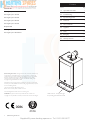
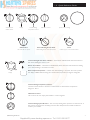
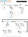
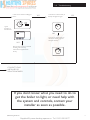
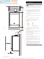
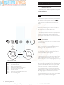
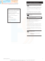
User’s Operating Instructions &
Important Warranty Information
Baxi Megaflo System HE IE Range
Gas Fired Wall Mounted Condensing Boiler
Please keep these instructions in a safe place.
If you move house, please hand them over to the next occupier.
© Baxi Heating UK Ltd 2011
Supplied By www.heating spares.co Tel. 0161 620 6677
Contents
Section
Natural Gas
Page
1.0
Quick Reference Guide
3
Baxi Megaflo System 18 HE IE
2.0
Troubleshooting
4
Baxi Megaflo System 24 HE IE
3.0
Repressurising System
6
4.0
Clearances
7
5.0
Care of the Boiler
8
6.0
Legislation
9
7.0
Notes
10
8.0
Emergency
11
9.0
Warranty & Service
12
Baxi Megaflo System 15 HE IE
Baxi Megaflo System 28 HE IE
Baxi Megaflo System 32 HE IE
Propane Gas
Baxi Megaflo System 24 HE IE LPG
Baxi Megaflo System 28 HE IE LPG
© Baxi Heating UK Ltd 2011 All rights reserved. No part of this publication may
be reproduced or transmitted in any form or by any means, or stored in any
retrieval system of any nature (including in any database), in each case whether
electronic, mechanical, recording or otherwise, without the prior written
permission of the copyright owner, except for permitted fair dealing under
Copyrights, Designs and Patents Act 1988.
Applications for the copyright owner’s permission to reproduce or make other
use of any part of this publication should be made, giving details of the proposed
use, to the following address:
The Company Secretary, Baxi Heating UK Ltd,
Brooks House, Coventry Road, Warwick. CV34 4LL
Full acknowledgement of author and source must be given.
WARNING: Any person who does any unauthorised act in relation to a
copyright work may be liable to criminal prosecution and civil claims for damages.
Boiler Controls - see opposite page
for Operating Quick Reference Guide
0086
ISO 9001
FM 00866
2
© Baxi Heating UK Ltd 2011
Supplied By www.heating spares.co Tel. 0161 620 6677
1.0 Quick Reference Guide
2
1
3
4
0
bar
ON/OFF/Reset
Selector Switch
Display
Central Heating
Temperature Control
Calibration Control
System Pressure Gauge
OFF Position
Central Heating & Hot Water
Reset
The boiler will not operate.
Both Heating & Hot Water will operate.
Hold for approx 5 seconds and release.
Central Heating & Hot Water Indicator - The indicator will illuminate when the boiler is in
the central heating/hot water mode.
Burner On Indicator - The indicator will illuminate when the burner has fired and is heating
your central heating or domestic hot water.
Boiler Output Temperature - In either the central heating or domestic hot water position
the display will illuminate showing the current boiler temperature in degrees centigrade.
Display
Central Heating Temperature Control
Turn the knob clockwise to increase or anticlockwise to decrease the temperature.
Range 25 - 80° C.
Calibration Control
This control is for use only by the installer or service engineer.
2
1
3
Central Heating System Pressure - The normal operating water pressure is at least 0.2 bar. If
the pressure exceeds 3 bar the safety pressure valve will operate and a fault is indicated.
Contact your Installer.
4
0
bar
3
© Baxi Heating UK Ltd 2011
Supplied By www.heating spares.co Tel. 0161 620 6677
Boiler not working
2.0 Troubleshooting
START
Make sure the gas supply is
turned ON and check if other
gas appliances are operating
(e.g. fire, cooker).
YES
Is the ON/OFF/Reset
Select Switch in the
(
) position ?
Is the (
(
) on ?
YES
) light on and the
NO
Central Heating
Indicator
NO
If no gas, consult your
supplier.
Is the display lit ?
YES
Burner On
Indicator
Boiler operating satisfactorily.
Display
NO
Check electricity to the
boiler is switched on.
Is the Central Heating System
Pressure above 0.2 bar ?
YES
Does the display show an error
code e.g. E133, E110 ?
NO
NO
2
1
3
4
0
bar
If the reading falls below 0.2 bar
see Section 3.1.
YES
Turn the ON/OFF/Reset
Selector Switch to Reset.
If boiler does not
Reset
Error Code E119 showing low
pressure.
4
© Baxi Heating UK Ltd 2011
Supplied By www.heating spares.co Tel. 0161 620 6677
2.0 Troubleshooting
Is the Timer ON and calling for
heat ?
12
Is the Room Thermostat (if
fitted) set high enough ?
10
15
20
25
4
8
5
3
9
2
5
6
CH ON
CH OFF
NO
Turn Room Thermostat to
maximum setting (typical
example shown).
NO
10
15
20
25
Ensure timer is set for Central
Heating ON (see any
instructions supplied with
timer).
5
7
Typical
examples of
external timer
YES
1
10
11
YES
CONTACT YOUR
INSTALLER OR
SERVICE ENGINEER.
If you don’t know what you need to do to
get the boiler to light, or need help with
the system and controls, contact your
installer as soon as possible.
5
© Baxi Heating UK Ltd 2011
Supplied By www.heating spares.co Tel. 0161 620 6677
3.0 System Pressure
3.1
2
1
3
4
0
Normal MINIMUM Pressure
2
1
3
4
0
bar
Fig. 2
Requires
Repressurising
2
1
3
4
0
bar
Fig. 3
1. The boiler may be installed in two types of heating
system, ‘sealed’ or ‘semi - sealed’. Your installer will be
able to advise you of the type of system and explain the
operation.
2. The ‘sealed’ type is pressurised from the mains by
means of a device called the filling loop, which may also
be used to re-pressurise the system.
bar
Fig. 1
Central Heating System Pressure
Fault
3. The ‘semi - sealed’ type relies on a header tank of
water to fill the system through a non - return valve.
This type of system should automatically maintain
suitable pressure.
4. The normal operating water pressure must be at least
0.2 bar (Fig. 1) for the boiler to operate. If the pressure
exceeds 3 bar (Fig. 3) the safety pressure valve will
operate and a fault is indicated. Contact your installer.
‘Sealed’ Systems Only
5. It may be necessary to repressurise the system
occasionally (Fig. 2). A filling device (the filling loop) will
be fitted on the system.
6. If you are unsure of its position, or cannot identify it,
consult the installer who fitted the boiler.
7. The filling loop consists of two taps and a separate
metal braided hose with connection fittings.
8. Only when repressurising should the hose be
connected between the two taps. Ensure that the nuts
on the pipe ends are tightened onto the taps.
9. Fully open one of the taps first, and then while
watching the pressure gauge, carefully open the second
tap.
10. When the needle on the gauge is indicating 0.2 or
more turn both taps off.
11. Disconnect the metal braided hose from the taps (a
small amount of water may be present) and remove it.
Keep the hose in a safe place for future use.
‘Semi - Sealed’ Systems Only
12. The header tank on the ‘semi - sealed’ system should
maintain the pressure at a minimum of 0.2 bar. If the
pressure drops below this consult your installer.
6
© Baxi Heating UK Ltd 2011
Supplied By www.heating spares.co Tel. 0161 620 6677
4.0 Clearances
450mm
5mm Min
5mm Min
200mm Min
(300mm Min if
using 80/125mm
flueing system)
4.1
For your Safety
1. This appliance must have been installed in accordance
with the manufacturer’s instructions and the regulations
in force.
2. Any modification that may interfere with the normal
operation of the appliance without express written
permission from the manufacturer or his agent could
invalidate the appliance warranty.
3. Your boiler must not be operated without the casing
correctly fitted.
4. Do not interfere with any sealed components on this
boiler.
5. Take note of any warning labels on your boiler.
780mm
6. Your boiler should have the following minimum
clearances for Safety and Maintenance
(Figs. 4 & 5):Top
Bottom
Left side
Right Side
Front
Fig. 4
150mm Min*
- 200mm
- 150mm
- 5mm
- 5mm
- 5mm (In Operation)
- 450mm (For Servicing)
*This is the MINIMUM recommended dimension.
Greater clearance than this will aid installation and
maintenance.
7. If your boiler is installed in a compartment, do not use
it for storage purposes. Do not obstruct any purpose
provided ventilation openings.
8. Flammable materials must not be stored in close
proximity to your boiler.
9. Avoid skin contact when your boiler is in operation, as
some surfaces may get hot e.g. pipework.
10. Ensure that the flue terminal, outside the house,
does not become damaged or obstructed, particularly
by foliage.
11. It is important that the condensate drain system is
not blocked, modified or damaged in any way as this
would affect the operation of your boiler. Your installer
should have insulated any exposed pipework.
450mm Min
For Servicing
Purposes
5mm Min
Fig. 5
In Operation
7
© Baxi Heating UK Ltd 2011
Supplied By www.heating spares.co Tel. 0161 620 6677
5.0 Care of the Boiler
5.1
Cleaning the Outer case
1. The painted panels should be wiped with a damp cloth
and then dried completely. DO NOT USE ABRASIVE
CLEANING AGENTS.
5.2
Protection & Precaution
1. The boiler incorporates an integral frost protection feature
that will operate when the selector switch is in (
)
position. If the boiler temperature falls below 5° C, then the
boiler will operate until the water temperature has been
raised.
2. If a system frost thermostat has been fitted (your installer
will be able to advise you), then to operate correctly and
protect your system, the gas and electricity must be left on and
the appliance set in the central heating mode.
3. The boiler incorporates an integral pump protection feature
which continually monitors the time since the pump last
operated. To prevent seizure, the pump will operate for
approximately 1 minute if it has not run in the last 24 hours.
5.3
Fault Indication
2
1
3
4
0
bar
2. The codes are either two or three digit, preceded by the
letter 'E'. For example, code E133 will be displayed by 'E1'
alternating with '33'. E50 is shown as 'E' then '50'.
Display
Then
Fig. 6
Table of Error Codes
E20
E28
E50
E110
E119
E125
E130
E133
E160
8
1. If a fault occurs on the boiler an error code may be shown
on the facia display.
Central Heating NTC Fault
Flue NTC Fault
Hot Water NTC Fault
Safety Thermostat Operated
Water Pressure Switch Not Operated
Circulation Fault (Primary Circuit)
Flue NTC Operated
Interruption Of Gas Supply or Flame Failure
Fan or Fan Wiring Fault
3. E20, E28, E50, E125 & E160 indicate faulty components.
You should make a note of the displayed error code and
contact your installer or service engineer.
4. If E110 or E130 is displayed overheat of the primary water
or flue system has occurred. Turn the selector switch to the
reset position and hold for at least 5 seconds. If the boiler
does not relight, or the code is displayed regularly contact your
installer or service engineer.
5. E119 is displayed when the primary water pressure is less
than 0.5 bar. After repressurising the system the boiler should
operate. Your installer will be able to advise you about the
method of repressurising. See page 6 for further details.
6. E133 indicates that the gas supply has been interrupted,
ignition has failed or the flame has not been detected. Ensure
that the gas supply has not been turned off, and turn the
selector switch to the reset position and hold for at least 5
seconds. If the boiler does not relight, or the code is displayed
regularly contact your installer or service engineer.
© Baxi Heating UK Ltd 2011
Supplied By www.heating spares.co Tel. 0161 620 6677
6.0 Legislation & Maintenance
6.1
The boiler meets the requirements of
Statutory Instrument “The Boiler (Efficiency)
Regulations 1993 No 3083” and is deemed to
meet the requirements of Directive
92/42/EEC on the energy efficiency
requirements for new hot water boilers fired
with liquid or gaseous fuels:Type test for purpose of Regulation 5
certified by:
Notified Body 0085.
Product/Production certified by:
Notified Bodies 0085 & 0086.
For IE only.
Installation, Commissioning, Service & Repair
1. This appliance must be installed in accordance with the
manufacturer’s instructions and the regulations in force.
Read the instructions fully before installing or using the
appliance.
2. The installation must be carried out by a competent
person as stated in I.S. 813 “Domestic Gas Installations”.
6.2
Spare Parts
IMPORTANT - Only a competent person should be
used to service or repair this boiler.
1. Any repairs to the boiler will usually be the
responsibility of the Installer during the guarantee period
after which spare parts may be obtained from
Heatmerchants if required.
2. Quote the appliance name, model number and where
possible the part number when ordering spares. A parts
list is included in the Installation and Servicing Instructions.
3. The name, model number and serial number can be
found on the information label on the back of the hinged
lower door.
6.3
After Sales Service
1. If After Sales Service is required please telephone:090 6424 062.
9
© Baxi Heating UK Ltd 2011
Supplied By www.heating spares.co Tel. 0161 620 6677
7.0 Notes
10
© Baxi Heating UK Ltd 2011
Supplied By www.heating spares.co Tel. 0161 620 6677
8.0 Emergency
Warning !
If you smell gas
Turn off the gas supply at the meter and call your gas
supplier immediately. It is possible to isolate the boiler at
the isolating valve (Fig. 8).
Faulty boiler
If it is known or suspected that a fault exists
on the boiler, it must not be used until the fault
has been corrected by a competent person.
In an Emergency
If a water or gas leak occurs or is suspected, the boiler can
be isolated at the inlet valves as follows;
Fig. 9
Gas Tap
1. Using a suitable open ended spanner, turn the square
nut on the gas tap through 90° (1/4 turn) in a clockwise
direction to isolate the gas supply at the boiler (Fig. 8).
2. The water isolating valves are positioned under the
boiler and can be closed by turning their taps to the right
towards the wall (Fig. 9).
Fig. 8
3. Call your Installer or Service Engineer as soon as
possible.
Heating Flow and
Heating Return Inlet
Isolating Valves
11
© Baxi Heating UK Ltd 2011
Supplied By www.heating spares.co Tel. 0161 620 6677
Please complete the boxes below
Serial Number
Contact us
For general enquiries contact branches
nationwide
For technical advice please contact
056 7720 023
Date of Installation
For in warranty service contact
090 6424 062
D D M M Y Y
Installer Details (name, address and contact number(s))
Branches Nationwide
www.heatmerchants.ie
For technical enquiries please contact
[email protected]
All descriptions and illustrations provided in this leaflet have been carefully
prepared but we reserve the right to make changes and improvements in
our products which may affect the accuracy of the information contained in
this leaflet. All goods are sold subject to our standard Conditions of Sale
which are available on request.
BAXI
A Tr a din g D i v i s i on o f B ax i Heat i ng U K Lt d ( 3879156)
Brooks House, Coventry Road, Warwick. CV34 4LL
Website www.baxi.co.uk
e&oe
© Baxi Heating UK Ltd 2011
UK Comp No 5129839 - Iss 5 - 3/11
Supplied By www.heating spares.co Tel. 0161 620 6677