1
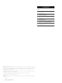
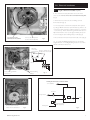
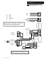
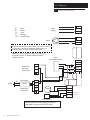
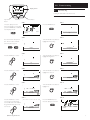
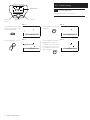
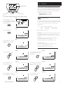
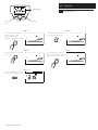
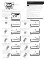
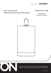
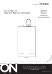
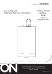
Installation & Servicing Instructions
Ecogen
Domestic Hot Water Tank Sensor
© Baxi Heating UK Ltd 2009
CONTENTS
Section
© Baxi Heating UK Ltd 2009 All rights reserved. No part of this publication may be reproduced or transmitted in any form or by
any means, or stored in any retrieval system of any nature (including in any database), in each case whether electronic, mechanical,
recording or otherwise, without the prior written permission of the copyright owner, except for permitted fair dealing under
Copyrights, Designs and Patents Act 1988.
Applications for the copyright owner’s permission to reproduce or make other use of any part of this publication should be made,
giving details of the proposed use, to the following address:
The Company Secretary, Baxi Heating UK Ltd, The Wyvern Business Park, Stanier Way, Derby, DE21 6BF.
Full acknowledgement of author and source must be given.
WARNING: Any person who does any unauthorised act in relation to a copyright work may be liable to criminal prosecution and
civil claims for damages.
2
© Baxi Heating UK Ltd 2009
Page
1.0
Introduction
3
2.0
Electrical Installation
4
3.0
Electrical
6
4.0
Commissioning
9
5.0
Functions - Legionella & DHW Eco
11
6.0
Fault Finding
15
1.0 Introduction
1.1
Description
1. These instructions provide details for installing the Ecogen
Domestic Hot Water (DHW)Tank Sensor with an Ecogen
24/1.0 and a Megaflo HE unvented domestic hot water cylinder.
The Ecogen DHW Tank Sensor is used to control the domestic
hot water cylinder temperature. It also enables the capability for
the end user to view and alter the domestic hot water
temperature using the Ecogen 24/1.0 user interface, as well as
providing a high level of domestic hot water comfort and energy
efficiency.
1.2
Important Notes
1. The Ecogen DHW Tank Sensor is only to be installed with a
Megaflo HE unvented DHW tank.
2. Ensure all equipment is isolated from the main supply before
the installation is started.
3. The Ecogen DHW Tank Sensor can only be used if the
distance between the Ecogen 24/1.0 appliance and the domestic
hot water is less than 10m.
4. All electrical wiring must be carried out by a competent
electrician and must be in accordance with the current IEE
(BS 7671) Requirements for Electrical Installation (Wiring
Regulations) and any local regulations.
5. DO NOT INSTALL the Ecogen DHW Tank Sensor if a
sensor pocket and sensor cable retention is not provided.
6. Unvented domestic hot water cylinder installations:
a) Refer to Megaflo HE instructions for the hydraulic installation.
b) The Ecogen 24/1.0 can only be installed with a Heatrae Sadia,
Megaflo HE unvented cylinder. The installation of any other
unvented cylinder will contravene the Water Regulations and
Building Regulations for installations of un-vented domestic hot
water cylinders.
c) To comply with Building Regulations and to prevent the
Megaflo HE from over heating, all wiring must be in accordance
with the schematics in Section 3.0 Electrical.
7. Ensure that the immersion is switched off while the Ecogen
appliance is providing heat.
8. Refer to Ecogen 24/1.0 Installation Instructions for heating
system configuration details.
1.3
Codes of Practice
Standard
BS 7671
BS 60730-2-9
BS 5546
BS 5449
BS 7593
© Baxi Heating UK Ltd 2009
Scope
I.E.E Wiring Regulations.
Automatic electrical controls for household
and similar use.
Installation of hot water supplies for DHW
purposes.
Forced circulation hot water systems.
Treatment of water in domestic hot water
central heating systems.
3
2.0 Electrical Installation
2.1
Overheat Thermostat
Temperature Control
Thermostat
Megaflo HE Electrical Installation
1. Ensure that all points in Section 1.0 have been observed.
2. Ensure that the Megaflo HE Installation Instructions have been
followed and completed.
Immersion Heater
Thermostat
Terminal Block
Indirect Thermal
Control
Temperature Control
Thermostat
Overheat
Thermostat
Tab 2
Link Wire
Wire B
Tab 1
4. Remove immersion heater thermostat by pulling thermostat
off by hand (Fig. 1).
5. Disconnect wire A at terminal block 3 end leaving the other
tab end attached to the temperature control thermostat.
Disconnect wire B at temperature control thermostat Tab 2 end
leaving the other end screwed into terminal block 2 (Fig. 1).
6. There is a link wire between the overheat thermostat and the
temperature control thermostat; disconnect the link wire
connection tab 1 from the over heat thermostat (Fig. 1).
Wire A
7. The temperature control thermostat can now be removed by
unscrewing the two retaining screws (Fig. 2).
Terminal
Block
Fig. 1
1
2
3
Retaining Screws
Disconnect Link
Wire
Disconnect Wire A
Remove the Temperature
Control Thermostat
Disconnect Tab 2
Disconnect Tab 1
Fig. 2
Disconnect
Terminal Block 3
Terminal
Block
1
4
3. The Megaflo HE cylinder will be supplied with the following
controls wiring centre - see Fig. 1.
© Baxi Heating UK Ltd 2009
2
3
2.0 Electrical Installation
2.1
Megaflo HE Electrical Installation (cont)
8. The control thermostat phial is then removed from the
sensor pocket. Do not remove the over heat thermostat phial.
(Fig. 3)
9. Wire B Tab 2 is connected to the remaining overheat
thermostat tab 2 (Fig. 4).
10. The temperature control thermostat phial is then replaced
by a Ecogen DHW Tank Sensor (PN: 720027001). (This is to be
connected to the Ecogen 24/1.0 cylinder tank sensor connection
- see Section 3.0). Ensure that the Ecogen DHW Tank Sensor is
fully inserted into the sensor pocket (approximately 15cm) and
is secured using the cable retaining clamp provided (Fig. 4).
Do Not Remove the
Overheat Thermostat Phial
Remove the Temperature
Control Thermostat Phial
11. Re-connect the immersion heater thermostat control (Fig. 5).
Fig. 3
12. To comply with Building Regulations and to prevent the
Megaflo HE from over heating, all wiring must be in accordance
with the schematics in Section 3.0.
Overheat
Thermostat
Connect Wire B Tab 2 to
the Overheat Thermostat
Tab 2
1
Cable Retaining
Insert the Ecogen DHW
Tank Sensor
Clamps
2
3
Fig. 4
Primary Connections to Indirect Units
To Hot Outlet
Air Vent
Primary Return
Inlet
Reconnect the Immersion
Heater Thermostat Control
© Baxi Heating UK Ltd 2009
Primary Flow
Fig. 5
2 Port Motorised
Valve (Supplied)
Fig. 6
5
3.0 Electrical
3.1
Bl Br Gr O G/Y -
Blue
Brown
Grey
Orange
Green/Yellow
S-Plan with Cylinder Sensor (Recommended)
Mains
Supply.
N
L
Pump
8
Fused
**
If space is limited due to the number of common wires,
it may help to create an additional wiring centre to
connect common wires to the Ecogen boiler
8 8
Isolate
Gr
O
Fused
2 Port Valve
Fused
CH1
Br
1
DHW Tank
Overheat
Thermostat
Br
2
3
**
Bl
G/Y
N
L
E
(Out)
N
L
(Out)
Boiler On (In)
CH1
CH2
Isolate
Gr
Bl
O
DHW
Br
O
Room Sensor
NOTE: Isolate the valve supply (grey) and the
ON signal (orange) from the zone valves
6
© Baxi Heating UK Ltd 2009
(On)
N
Valve
Valve
(Out)
(In)
Out Door
Sensor (Out)
Out Door
Sensor (In)
Tank
Sensor (Out)
Tank
Sensor (In)
1
Room
Unit (+12v)
2
Room
(Ground OV)
Unit
(-)
3
Room
(Data Signal +V)
Unit
(+)
G
DHW Tank
Zone Valve
(On)
DHW(On)
DHW(Off)
C/S
C/S
2 Port Valve
(Out)
3.0 Electrical
3.2
Bl Br Gr O G/Y W -
Y-Plan with Cylinder Sensor
Mains
Supply.
Blue
Brown
Grey
Orange
Green/Yellow
White
N
L
Pump
8
Fused
**
If space is limited due to the number of common wires,
it may help to create an additional wiring centre to
connect common wires to the Ecogen boiler
8 8
Fused
Fused
3 Port
Mid Position Valve
1
DHW Tank
Overheat
Thermostat
V1
2
3
W
N
L
E
(Out)
N
L
(Out)
(Out)
Boiler On (In)
CH1
CH2
(On)
(On)
DHW(On)
Gr
DHW(Off)
** Bl
Valve N
G/Y
Valve
C/S
C/S
Isolate
Gr
2 Port Valve
Bl
O
DHW
Br
(In)
Out Door
Sensor (Out)
Out Door
Sensor (In)
Tank
Sensor (Out)
Tank
Sensor (In)
1
Room
Unit (+12v)
2
Room
(Ground OV)
Unit (-)
3
Room
(Data Signal +V)
Unit (+)
G
DHW Tank
Zone Valve
(Out)
O
Room Sensor
NOTE: Isolate the valve supply (grey) and the
ON signal (orange) from the zone valves
© Baxi Heating UK Ltd 2009
7
3.0 Electrical
3.3
Bl Br Gr O G/Y -
W-Plan with Cylinder Sensor
Mains
Supply.
Blue
Brown
Grey
Orange
Green/Yellow
N
L
Pump
8
Fused
**
If space is limited due to the number of common wires,
it may help to create an additional wiring centre to
connect common wires to the Ecogen boiler
8 8
NOTE: The valve should rest in the CH position.
The valve is driven to DHW position if there is
a DHW demand.
Fused
Fused
3 Port
Spring Return Valve
Br
**
2
3
E
(Out)
N
L
(Out)
Bl
G/Y
Isolate
2 Port Valve
Bl
O
DHW
Br
O
Room Sensor
NOTE: Isolate the valve supply (grey) and the
ON signal (orange) from the zone valves
8
© Baxi Heating UK Ltd 2009
(On)
Valve
N
Valve
(Out)
(In)
Out Door
Sensor (Out)
Out Door
Sensor (In)
Tank
Sensor (Out)
Tank
Sensor (In)
Room
1
Unit (+12v)
Room
2
(Ground OV)
Unit (-)
Room
3
(Data Signal +V)
Unit (+)
G
DHW Tank
Zone Valve
(On)
DHW(On)
DHW(Off)
C/S
C/S
Gr
(Out)
Boiler On (In)
CH1
CH2
1
DHW Tank
Overheat
Thermostat
N
L
4.0 Commissioning
Display Screen
04. November
Tuesday
2008
4.1
08:50
Commissioning
1. Using the boiler HMI or the Room unit.
Easy Menu
Button
Menu Button
Dial Knob
STEP 1
STEP 2
The basic display is shown.
If the basic display is not showing,
press the MENU button untill the
basic display is shown
Press the MENU button.
04. November
Tuesday
2008
08:50
--------------------------------------------------Info
Time of day and date
STEP 3
STEP 4
Press and hold the “Easy Menu”
and “ Menu” buttons until the
user level options appear.
Turn the Dial Knob clockwise to
highlight Commissioning.
--------------------------------------------------Enduser
Commissioning
Enduser
Commissioning
Engineer
STEP 5
STEP 6
Turn the Dial Knob clockwise to
highlight Configuration.
Press the Dial Knob to select .
--------------------------------------------------Info
Time of day and date
Domestic hot water
Configuration
Fault
STEP 7
STEP 8
Press the Dial Knob to select .
Turn the Dial Knob clockwise to
highlight Save Sensors.
Configuration
Frost protection plant
Configuration
Save sensors
Off
No
STEP 9
STEP 10
Turn the Dial Knob clockwise to
highlight Yes.
Press the Dial Knob to select .
Configuration
Save sensors
Configuration
Save sensors
No
Yes
STEP 11
Press the Dial Knob to select.
The selection Yes will change
back to NO. This means that the
Ecogen DHW Tank Sensor has
been saved.
STEP 12
Press the MENU button for
the basic display to be shown.
Configuration
Save sensors
04. November
Tuesday
2008
08:50
No
© Baxi Heating UK Ltd 2009
9
4.0 Commissioning
Display Screen
04. November
Tuesday
2008
4.1
08:50
Commissioning Ccont)
1. Using the boiler HMI or the Room unit.
Easy Menu
Button
Menu Button
Dial Knob
STEP 13
STEP 14
To check that the Ecogen DHW
Tank Sensor is working correctly,
press the MENU button.
Turn the Dial Knob clockwise to
highlight Info.
--------------------------------------------------Info
Time of day and date
--------------------------------------------------Info
Time of day and date
STEP 15
STEP 16
Press the Dial Knob to select .
Info
Room temperature
10
© Baxi Heating UK Ltd 2009
Turn the Dial Knob clockwise to
highlight DHW 1 Temp. If no
temperature can be seen, check
the wiring is secure and correct
to the instructions. Then repeat
again from Step 1.
Info
DHW temp 1
--- °C
5.0 Functions
Display Screen
04. November
Tuesday
Easy Menu
Button
2008
1. As a result of successfully installing the Ecogen DHW Tank
Sensor, the user will have the ability to change the domestic hot
water temperature set point and view the current domestic hot
water temperature via the boiler HMI or the Room Unit. Two
additional functions will also be available:
Legionella function See section 5.1.
DHW Eco function See section 5.2.
08:50
Menu Button
Dial Knob
To select and configure the function for Periodically operation
STEP 1a
5.1
The basic display is shown.
If the basic display is not showing,
press the MENU button untill the
basic display is shown
04. November
Tuesday
2008
08:50
Legionella function
1. Legionella is a function that helps to prevent bacteria building
up in your domestic hot water tank. The legionella function heats
up your domestic hot water to 65°C for 30 minutes at predefine intervals.
2. There are three options for legionella:
Off
Periodically
Fixed Weekday
STEP 2a
Press the MENU button.
Off - Legionella is deactivated.
--------------------------------------------------Info
Time of day and date
STEP 3a
Turn the Dial Knob clockwise to
highlight Domestic hot water.
Periodically - This gives the user the option to select how often
and at what time legionella is repeated during the week. If
Periodically is selected two parameters are used to confgure this
selection:
Legionella function period (Parameter 1641) (Default = 1,
therefore legionella activated every day).
Legionella time (Parameter 1644) (Default = 08:00).
Periodically example:
If the user selects Legionella function period = 3 and
If the user selects Legionella time = 12:00
Legionella is activated at 12:00 every 3 days.
Heating circuit 1
Domestic hot water
Diagnostic
STEP 4a
STEP 5a
Press the Dial Knob to select .
Turn the Dial Knob clockwise to
show Legionella function. The
default is Off.
Domestic hot water
Operating mode
Domestic hot water
Legionella function
On
Off
STEP 6a
STEP 7a
Press the Dial Knob so the
selection starts to flash.
Turn the Dial Knob clockwise to
select Periodically. Press knob to
confirm.
Domestic hot water
Legionella function
Domestic hot water
Legionella function
Periodically
Off
STEP 10a
STEP 9a
Press the Dial Knob so the
selection starts to flash.
Turn the Dial Knob clockwise to
show Legionella funct periodically.
Domestic hot water
Legionella funct periodically
Domestic hot water
Legionella funct periodically
1
© Baxi Heating UK Ltd 2009
1
11
5.0 Functions
Display Screen
04. November
Tuesday
Easy Menu
Button
2008
5.1
08:50
Legionella function (cont)
Menu Button
Dial Knob
STEP 11a
STEP 12a
Turn the Dial Knob clockwise to
select Legionella function time.
Turn the Dial Knob clockwise to
select the number of days
between each legionella
operation. Press knob to confirm.
Domestic hot water
Legionella funct periodically
Domestic hot water
Legionella funct time
3
--:--
STEP 14a
STEP 13a
Press the Dial Knob so the value
starts to flash.
Turn the Dial Knob clockwise to
choose a time at which Legionella
will start. Press knob to confirm.
Domestic hot water
Legionella funct time
Domestic hot water
Legionella funct time
--:--
STEP 15a
Press the MENU button to return
to the normal operating screen.
04. November
Tuesday
12
© Baxi Heating UK Ltd 2009
2008
08:50
12:00
5.0 Functions
Display Screen
04. November
Tuesday
Easy Menu
Button
2008
5.1
08:50
Menu Button
Dial Knob
To select and configure the function for Fixed Weekday operation
Legionella function (cont)
Fixed Weekday - This gives the user the option to select the
particular day and at what time legionella is activated during the
chosen day. If Fixed Weekday is selected two parameters are
used to configure this selection:
Legionella function weekday (Parameter 1642) (Default =
Monday).
Legionella time (Parameter 1644) (Default = 08:00).
STEP 1b
Fixed Weekday example:
If the user selects Legionella day = Wednesday and
If the user selects Legionella time = 12:00
Legionella is activated at 12:00 every Wednesday.
The basic display is shown.
If the basic display is not showing,
press the MENU button untill the
basic display is shown
04. November
Tuesday
2008
08:50
STEP 3b
STEP 2b
Press the MENU button.
Turn the Dial Knob clockwise to
highlight Domestic hot water.
--------------------------------------------------Info
Time of day and date
Heating circuit 1
Domestic hot water
Diagnostic
STEP 4b
STEP 5b
Turn the Dial Knob clockwise to
show Legionella function. The
default is Off.
Press the Dial Knob to select .
Domestic hot water
Operating mode
Domestic hot water
Legionella function
On
Off
STEP 6b
STEP 7b
Turn the Dial Knob clockwise to
select Fixed weekday. Press knob
to confirm.
Press the Dial Knob so the
selection starts to flash.
Domestic hot water
Legionella function
Domestic hot water
Legionella function
Fixed weekday
Off
STEP 10b
STEP 9b
Turn the Dial Knob clockwise to
show Legionella funct weekday.
Press the Dial Knob so the value
starts to flash.
Turn the Dial Knob clockwise to
select the day when legionella will
be activated. Press knob to
confirm.
Domestic hot water
Legionella funct weekday
Wednesday
Domestic hot water
Legionella funct weekday
Monday
STEP 11b
STEP 12b
Turn the Dial Knob clockwise to
select legionella function time.
Press knob to confirm and to
start the value flashing.
Turn the Dial Knob clockwise to
choose a time at which Legionella
will start. Press knob to confirm.
Domestic hot water
Legionella funct time
Domestic hot water
Legionella funct time
--:--
© Baxi Heating UK Ltd 2009
12:00
13
5.0 Functions
Display Screen
04. November
Tuesday
Easy Menu
Button
2008
08:50
5.1
Legionella function (cont)
5.2
DHW Eco function
Menu Button
Dial Knob
STEP 13b
Press the MENU button to return
to the normal operating screen.
04. November
Tuesday
2008
08:50
To use the DHW Eco function; from the normal operating screen
STEP 1c
Press the MENU button.
--------------------------------------------------Info
Time of day and date
CAUTION – This function will increase the recovery time
of the domestic hot water cylinder temperature. Users
should adjust the domestic hot water time switch program
to start the boiler sooner to allow sufficient time for the
water to be heated to the desired water temperature.
1. The DHW Eco function prevents the 2nd burner from
starting for domestic hot water demands only. This means that
during a domestic hot water demand only the Stirling engine
burner is used, hence the recovery time is longer but more
electrical power is generated.
STEP 2c
Turn the Dial Knob clockwise to
highlight Domestic hot water.
Heating circuit 1
Domestic hot water
Diagnostic
STEP 3c
STEP 4c
Turn the Dial Knob clockwise to
show Burner sequence. The
default setting is No restriction.
Press the Dial Knob to select .
Domestic hot water
Operating mode
Domestic hot water
Burner sequence
No restriction
On
STEP 5c
STEP 6c
Turn the Dial Knob clockwise to
select Eng bu only. Press the
knob to confirm.
Press the Dial Knob so the
selection starts to flash.
Domestic hot water
Burner sequence
No restriction
STEP 7c
Press the MENU button to return
to the normal operating screen.
04. November
Tuesday
14
© Baxi Heating UK Ltd 2009
2008
08:50
Domestic hot water
Burner sequence
Eng bu only
6.0 Fault Finding
6.1
Fault Finding
1. If an error “50: DHW Sensor 1” is displayed check the
Ecogen DHW Tank Sensor wiring is secure and correct to the
instructions.
2. If the domestic hot water is suspected to be too hot check
that the sensor has been securely fitted into the cylinder sensor
pocket provided. If an immersion heater is connected to the
cylinder, ensure that it is switched off while the Ecogen boiler is
providing heat to the Megaflo HE cylinder. Alternatively you
could try changing the day or time when the legionella function
is run. So that you are not using the hot water immediately
after the legionella has reached 65°C.
3. If the domestic hot water is not reaching the desired
temperature, check that the Ecogen DHW Tank Sensor has
been connected to the “Tank Sensor” connection terminals in
the Ecogen appliance electrical installation area. Also check that
the DHW Eco function has not been set to “Eng bu only”. You
may be able to improve this problem by setting the domestic
hot water time program to start sooner. Alternatively
deactivate the DHW Eco function by selecting “No restriction”
in the “Burner Sequence” menu (see section 5.2).
4. Refer to the Ecogen 24/1.0 and the Megaflo HE installation
and service instructions for more fault finding help.
5. If problems persist call Heateam.
© Baxi Heating UK Ltd 2009
15
All descriptions and illustrations provided in this leaflet have been carefully
prepared but we reserve the right to make changes and improvements in our
products which may affect the accuracy of the information contained in this
leaflet. All goods are sold subject to our standard Conditions of Sale which are
available on request.
BA X I
A Tr a din g D i v i s i on of B a x i Heat i ng U K Lt d ( 3879156)
A D ivis io n of B a x i Gro u p
Brooks House, Coventry Road, Warwick. CV34 4LL
After Sales Service 08700 60 30 60 Technical Enquiries 08706 049 049
Website www.baxi.co.uk
e&oe
© Baxi Heating UK Ltd 2009
Comp No 720027401 (6/09)