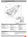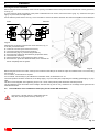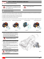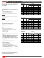
1
Installation, use and maintenance instructions
GB
Forced draught gas burners
Progressive two-stage or modulating operation
Code
Model
Type
3897430 - 3897432
RS 68/E BLU
846 T1
3897431 - 3897433
RS 68/E BLU
846 T1
3897630 - 3897632
RS 120/E BLU
847 T1
3897631 - 3897633
RS 120/E BLU
847 T1
3788030 - 3788032
RS 160/E BLU
843 T1
3788031 - 3788033
RS 160/E BLU
843 T1
3788050 - 3788052
RS 160/E BLU
843 T1
3788051 - 3788053
RS 160/E BLU
843 T1
3899800 - 3899810
RS 200/E BLU
1106 T1
3899801 - 3899811
RS 200/E BLU
1106 T1
3899830 - 3899840
RS 200/E BLU
1106 T1
3899831 - 3899841
RS 200/E BLU
1106 T1
3899880 - 3899881
RS 200/E BLU
1106 T81
3899882 - 3899883
RS 200/E BLU
1106 T81
3899884 - 3899885
RS 200/E BLU
1106 T81
3899886 - 3899887
RS 200/E BLU
1106 T81
2916350 (4) - 03/2008
Declaration of conformity in accordance with ISO / IEC 17050-1
Manufacturer:
RIELLO S.p.A.
Address:
Via Pilade Riello, 7
37045 Legnago (VR)
Product:
Forced draught gas burner
Model:
RS 68/E BLU
RS 120/E BLU
RS 160/E BLU
RS 200/E BLU
These products are in compliance with the following Technical Standards:
EN 676
EN 292
According to the European Directives:
GAD
MD
LVD
EMC
90/396/EEC
98/37/EEC
73/23/EEC - 2006/95/EC
89/336/EEC - 2004/108/EC
Gas Devices Directive
Machine Directive
Low Voltage Directive
Electromagnetic Compatibility
such products are marked as follows:
CE-0085BS0267 (for RS 68/E BLU)
CE-0085BS0268 (for RS 120/E BLU)
CE-0085BS0266 (for RS 160/E BLU)
CE-0085XXXXX (for RS 200/E BLU)
Legnago, 08.08.2007
Mr. G. Conticini
Burners Division Department
The quality is guaranteed by a quality and management system
certified in accordance with UNI EN ISO 9001.
2
GB
Contents
Section
1
2
3
Pag.
Information and general instructions
4
1.1
1.2
4
4
Safety and prevention
5
2.1
2.2
5
5
Introduction
Personnel training
Technical description of the burner
3.1
3.2
3.3
3.4
3.5
3.6
3.7
3.8
3.9
3.10
3.11
4
Information about the instruction manual
Guarantee and responsibility
Burner designation
Models available
Burner categories- Countries of destination
Technical data
Packaging
Overall dimensions
Firing rates
Burner components
Burner equipment
Control box for the air/fuel ratio
Servomotors
6
7
6
6
7
7
8
8
9
10
10
11
12
Installation
13
4.1
4.2
4.3
4.4
4.5
4.6
13
13
13
13
14
Notes on safety for the installation
Handling
Preliminary checks
Working position
Securing the burner to the boiler
Pre-calibration of the combustion head (only for
the model RS 120/E BLU)
4.7 Combustion head adjustment
4.8 Assembly of the gas train
4.9 Electrical wiring
4.10 Calibration of the thermal relay
5
6
15
16
18
19
20
Start-up, calibration and operation of the
burner
21
5.1
5.2
5.3
5.4
5.5
5.6
5.7
5.8
5.9
5.10
5.11
5.12
5.13
5.14
5.15
5.16
Notes on safety for the first start-up
Operations before start-up
Burner start-up
Final calibration of the pressure switches
Operator panel with LCD display
Visualisation and programming modes
Operation sequence of the burner
Start-up procedure
CALC function
Burner adjustment
Steady state operation
Ignition failure
Burner flame goes out during operation
Stopping of the burner
Measuring the ionisation current
Checking the air and gas pressure on the combustion head
5.17 Final checks (with the burner working):
5.18 List of parameters
21
21
22
22
24
25
30
31
33
33
34
34
34
34
34
34
Faults - Possible causes - Solutions
39
6.1
39
List of error codes
34
35
Maintenance
43
7.1
7.2
7.3
7.4
43
43
44
44
Notes on safety for the maintenance
Maintenance programme
Opening the burner
Closing the burner
A
Appendix - Electrical panel layout
45
B
Appendix - Accessories (optional)
52
C
Appendix - Gas supply pressure
53
D
Appendix - Firing rate on basis of air density
55
GB
3
1
1.1
Information and general instructions
Information about the instruction manual
Introduction
The instruction manual supplied with the burner:
DANGER: LIVE COMPONENTS
³ is an integral and essential part of the product and must not
be separated from it; it must therefore be kept carefully for any
necessary consultation and must accompany the burner even
if it is transferred to another owner or user, or to another system. If the manual is lost or damaged, another copy must be
requested from the Technical Assistance Service
of
the area;
DANGER
Other symbols
ENVIRONMENTAL PROTECTION
This symbol gives indications for the use of
the machine with respect for the environment.
³ is designed for use by qualified personnel;
³ offers important indications and instructions relating to the in-
stallation safety, start-up, use and maintenance of the burner.
³
Symbols used in the manual
In some parts of the manual you will see triangular DANGER
signs. Pay great attention to these, as they indicate a situation of
potential danger.
GENERAL DANGERS
The dangers can be of 3 levels, as indicated below.
DANGER
Maximum danger level!
This symbol indicates operations which, if not
carried out correctly, cause serious injury,
death or long-term health risks.
This symbol indicates operations which, if not
carried out correctly, may cause serious
injury, death or long-term health risks.
WARNING
This symbol indicates operations which, if not
carried out correctly, may cause damage to
the machine and/or injury to people.
CAUTION
1.2
This symbol indicates a list.
Abbreviations used
Ch.
Chapter
Fig.
Figure
Page
Page
Sec.
Section
Tab.
Table
Delivery of the system and the instruction manual
When the system is delivered, it is important that:
³ The instruction manual is consigned to the user by the system
manufacturer, with the recommendation to keep it in the room
where the heat generator is to be installed.
³ The instruction manual shows:
the serial number of the burner;
the address and telephone number of the nearest Assistance
Centre.
³ The system supplier must carefully inform the user about:
- the use of the system;
- any further tests that may be necessary before the system
is started up;
- maintenance and the need to have the system checked at
least once a year by the manufacturer or another specialised
technician.
To ensure a periodic check,
recommends the drawing up of a Maintenance Contract.
Guarantee and responsibility
guarantees its new products from the installation date, in
accordance with the regulations in force and/or the sales contract. At the moment of the first start-up, check that the burner is
integral and complete.
Failure to observe the information given in this
manual, operating negligence, incorrect installation
and the carrying out of non authorised modifications
WARNING
will result in the annulment by
of the
guarantee that it supplies with the burner.
In particular, the rights to the guarantee and the responsibility
will no longer be valid, in the event of damage to things or injury
to people, if such damage/injury was due to any of the following
causes:
³ incorrect installation, start-up, use and maintenance of the
burner;
³ improper, incorrect or unreasonable use of the burner;
³ intervention of unqualified personnel;
³ carrying out of non authorised modifications on the
equipment;
4
This symbol indicates operations which, if not
carried out correctly, lead to electric shocks
with lethal consequences.
GB
³ use of the burner with safety devices that are faulty,
incorrectly applied and/or not working;
³ installation of untested supplementary components on the
burner;
³ powering of the burner with unsuitable fuels;
³ faults in the fuel power supply system;
³ use of the burner even following an error and/or an
irregularity;
³ repairs and/or overhauls incorrectly carried out;
³ modification of the combustion chamber with inserts that
prevent the regular development of the structurally
established flame;
³ insufficient and inappropriate surveillance and care of those
burner components most subject to wear and tear;
³ use of non-original
components, including spare
parts, kits, accessories and optionals;
³ force majeure.
furthermore declines any and every responsibility
for the failure to observe the contents of this manual.
2
2.1
Safety and prevention
Introduction
The
burners have been designed and built in compliance
with current regulations and directives, applying the known technical rules of safety and envisaging all the potential danger situations.
It is necessary, however, to bear in mind that the imprudent and
clumsy use of the equipment may lead to situations of death risk
for the user or third parties, as well as the damaging of the burner
or other items. Inattention, thoughtlessness and excessive confidence often cause accidents; the same applies to tiredness and
sleepiness.
³
It is a good idea to remember the following:
³ The burner must only be used as expressly described. Any
other use should be considered improper and therefore dangerous.
³
³
³
2.2
In particular:
it can be applied to boilers operating with water, steam, diathermic oil, and to other users expressly named by the manufacturer;
the type and pressure of the fuel, the voltage and frequency
of the electrical power supply, the minimum and maximum deliveries for which the burner has been regulated, the pressurisation of the combustion chamber, the dimensions of the
combustion chamber and the room temperature must all be
within the values indicated in the instruction manual.
Modification of the burner to alter its performance and destinations is not allowed.
The burner must be used in exemplary technical safety conditions. Any disturbances that could compromise safety must
be quickly eliminated.
Opening or tampering with the burner components is not allowed, apart from the parts requiring maintenance.
Only those parts envisaged by the manufacturer can be replaced.
Personnel training
The user is the person, body or company that has acquired the
machine and intends to use it for the specific purpose. He is responsible for the machine and for the training of the people working around it.
The user:
³ undertakes to entrust the machine exclusively to suitably
trained and qualified personnel;
³ must take all the measures necessary to prevent unauthorised people gaining access to the machine;
³ undertakes to inform his personnel in a suitable way about the
application and observance of the safety instructions. With
that aim, he undertakes to ensure that everyone knows the
use and safety instructions for his own duties;
³ must inform the manufacturer if faults or malfunctioning of the
accident prevention systems are noticed, along with any presumed danger situation.
³ Personnel must always use the personal protective equip-
³
³
³
³
ment envisaged by legislation and follow the indications given
in this manual.
Personnel must follow all the danger and caution indications
shown on the machine.
Personnel must not carry out, on their own initiative, operations or interventions that are not within their province.
Personnel are obliged to inform their superiors of every problem or dangerous situation that may arise.
The assembly of parts of other makes, or any modifications,
can alter the characteristics of the machine and hence compromise operating safety. The manufacturer therefore declines any and every responsibility for any damage that may
be caused by the use of non-original parts.
GB
5
Technical description of the burner
3
3.1
Burner designation
Range :
R
Fuel :
S
L
LS
Natural gas
Light oil
Light oil / Natural gas
N
Heavy oil
Size
Adjustment :
E
EV
M
Electronic cam
Electronic cam and variable speed (with Inverter)
Mechanical cam
P
Proportional air/gas valve
Emission :
...
MZ
Class 1 EN267 (light oil) - EN676 (gas)
Class 2 EN267 (light oil) - EN676 (gas)
Blue
Class 3 EN267 (light oil) - EN676 (gas)
Class 1 EN267 (light oil)
Class 3 EN676 (gas)
MX
Head :
TC
TL
Standard head
Long head
Flame control system :
FS1 Standard (1 stop every 24h)
FS2 Continuous operation (1 stop every 72h)
Electrical supply of the system :
3N / 400V / 50Hz
3/400/50
3 / 230V / 50Hz
3/230/50
3/400-230/50
3N / 400V-230V / 50Hz
Voltage of auxiliaries :
230/50/60
230V/50-60Hz
110/50/60
110V/50-60Hz
R
S
120
E
Blue
TC
FS1
3/400/50
230/50/60
BASIC DESIGNATION
EXTENDED DESIGNATION
3.2
Models available
Designation
RS 68/E BLU
RS 68/E BLU
RS 120/E BLU
RS 120/E BLU
RS 160/E BLU
RS 160/E BLU
RS 160/E BLU
RS 160/E BLU
RS 200/E BLU
RS 200/E BLU
RS 200/E BLU
RS 200/E BLU
RS 200/E BLU
RS 200/E BLU
RS 200/E BLU
RS 200/E BLU
6
GB
TC
TL
TC
TL
TC
TL
TC
TL
TC
TL
TC
TL
TC
TL
TC
TL
Voltage
Code
3 ~ 400 / 230V - 50Hz
3 ~ 400 / 230V - 50Hz
3 ~ 400 / 230V - 50Hz
3 ~ 400 / 230V - 50Hz
3 ~ 230V - 50Hz
3 ~ 230V - 50Hz
3 ~ 400V - 50Hz
3 ~ 400V - 50Hz
3 ~ 400V - 50Hz
3 ~ 400V - 50Hz
3 ~ 230V - 50Hz
3 ~ 230V - 50Hz
3 ~ 220V - 60Hz
3 ~ 220V - 60Hz
3 ~ 380V - 60Hz
3 ~ 380V - 60Hz
3897430 - 3897432
3897431 - 3897433
3897630 - 3897632
3897631 - 3897633
3788030 - 3788032
3788031 - 3788033
3788050 - 3788052
3788051 - 3788053
3899800 - 3899810
3899801 - 3899811
3899830 - 3899840
3899831 - 3899841
3899880 - 3899881
3899882 - 3899883
3899884 - 3899885
3899886 - 3899887
Technical description of the burner
3
3.3
Technical data
Model
Type
Output (1)
RS 68/E BLU
maximum
minimum
Fuel
Gas pressure at max. output (2) Gas: G20/G25
Gas pressure at max. output (2) Gas: G31
Operation
Standard applications
Room temperature
Combustion air temperature
Electrical supply
Electric frequency
Fan motor (rating)
Operating current
Acceleration current
Ignition transformer
Absorbed electrical power
Protection level
Compliance with EC Directives
Noise level (3)
Type-approval
(1)
(2)
(3)
class 3
(EN 676)
kW
Mcal/h
kW
Mcal/h
mbar
RS 120/E BLU
RS 160/E BLU
RS 200/E BLU
846 T1
847 T1
843 T1
1106 T1
1106 T81
350 - 860
600 - 1300
930 - 1860
1375 - 2400
1375 - 2400
301 - 740
516 - 1118
800 - 1600
1183 - 2064
1183 - 2064
150
300
300
570
570
130
258
258
490
490
Natural gas: G20 (methane gas) - G21 - G22 - G23 - G25 - G31 (only RS 200/E BLU)
11.7 / 17.5
22.5 / 33.7
17.7 / 26.5
28 / 35.6
28 / 35.6
-
-
-
19.6
19.6
2800
230/400
5,5
21.3 - 12.3
144 - 83
3 ~ 220V /380V
1N ~ 220V
+/-10%
60 Hz
3400
220
4,5
15.8 - 9.1
126 - 72
6.5
5.3
83.0
83.0
In progress
-
mbar
Intermittent (min. 1 stop in 24 hours)
Boilers: water, steam, diathermic oil
°C
0 - 40
°C max 60
3 ~ 400V / 230 V 1N ~ 230V +/-10%
rpm
V
kW
A
A
V1 - V2
I1 - I2
kW max
dBA
EC
RS 200/E BLU
2800
230/400
1,5
6.1 - 3.5
78 - 39
50 Hz
2800
230/400
2,2
8.5 - 4.9
48 - 28
2800
230/400
4,5
15.8 - 9.1
126 - 72
230 V - 1 x 8 kV
1 A - 20 mA
5.3
2
2.8
IP 44
98/37 - 90/396 - 89/336 - 2004/108 - 73/23 - 2006/95
77
78.5
80.5
0085BS0267
0085BS0268
0085BS0266
Reference conditions: Room temperature 20°C - Gas temperature 15°C - Barometric pressure 1013 mbar - Altitude 0m above sea level.
Pressure on the pressure switch socket Fig. 27 with zero pressure in the combustion chamber and at maximum burner output.
Sound pressure measured in manufacturer's combustion laboratory, with burner operating on test boiler and at maximum output.
3.4
Burner categories - Countries of destination
Country of destination
Gas category
AT - CH - CZ - DK - EE - ES - FI - GB - GR - HU - IE - IS - IT - LT - LV - NO - PT - SE - Sl - SK - TR
I2H
DE
I2ELL
NL
I2L
FR
I2Er
BE
I2E(R)B
LU - PL
I2E
GB
7
Technical description of the burner
3
3.5
Packaging
• The packaging of the burner rests on a wooden platform that is particularly suitable for
lift trucks. The overall dimensions of the packaging are shown in the table.
• The weight of the burner complete with its packaging is shown in table.
mm
RS 68/E BLU
RS 120/E BLU
RS 160/E BLU
RS 200/E BLU
3.6
A
B
C
kg
1400
1400
1400
1400
780
780
780
780
700
700
1000
1000
77 - 79
83 - 85
96-98
101-103
D36
Fig. 1
Overall dimensions
The dimensions of the burner are shown in Fig. 2.
Bear in mind that inspection of the combustion head
requires the burner to be opened and the rear part
drawn back on the guides.
The dimensions of the open burner are indicated by
position I.
D1206
Fig. 2
mm
RS 68/E BLU
RS 120/E BLU
RS 160/E BLU
RS 200/E BLU
A
B
C
D
E
F (1)
G
H
I (1)
L
M
N
O
511
553
681
732
312
338
366
427
215
215
315
305
555
555
555
555
840
840
847
872
255-390
255-390
373-503
373-503
189
189
221
222
430
430
430
430
1161-1296
1161-1296
1442-1587
1442-1587
214
214
230
230
134
134
141
141
221
221
186
260
2”
2”
2”
2”
(1) Blast tube: short-long
8
GB
Technical description of the burner
3
3.7
Firing rates
RS 120/E BLU
Pressure in combustion
chamber mbar
Pressure in combustion
chamber mbar
RS 68/E BLU
A
A
RS 200/E BLU
A
Pressure in combustion
chamber mbar
Pressure in combustion
chamber mbar
RS 160/E BLU
B
A
Fig. 3
The maximum output is chosen within area A (and B for RS
120/E BLU) of the diagram.
NOTE: to use area B (RS 120/E BLU) as well, the pre-calibration
of the combustion head is necessary, as explained in Ch. 4.6.
Warning
The firing rate was obtained considering a room temperature of
20°C and an atmospheric pressure of 1013 mbar (approx. 0 m
above sea level), with the combustion head adjusted as shown
in Ch. 4.7.
RS 200/E BLU
The firing rate refers to the operation with fuel G20 - G25. In
case G31 is used, the minimum output goes from 570 to
630 kW.
The firing rates were obtained in special test boilers, according to EN 676
regulations.
Fig. 4 indicates the diameter and
length of the test combustion chamber.
Length of combustion
chamber
m
The minimum output must not be lower than the minimum limit
of the diagram.
D8615
Example
Output 756 kW (650 Mcal/h):
diameter 60 cm,
length 2m.
D715
The coupling is ensured when the
boiler is EC type-approved; for boilers
or ovens with combustion chambers of
very different dimensions compared to
those shown in the diagram of Fig. 4,
preliminary checks are recommended.
Fig. 4
GB
9
Technical description of the burner
3
3.8
Burner components
A
seen from A
Fig. 5
D7923
1
2
3
4
5
6
7
8
Combustion head
Ignition electrode
Screw for combustion head adjustment
Maximum gas pressure switch
Pipe coupling
Gas servomotor
Plug-socket on ionisation probe cable
Motor contact maker and thermal relay
with reset button
9 Operation on/off switch
10 Terminal board for electrical wiring
3.9
11 Operator panel with LCD display
12 Control box for checking flame and air/
fuel ratio
13 Clean contact relay
14 Filter to protect against radio disturbance
15 Flame inspection window
16 Ignition transformer
17 Cable grommets for electrical wiring
(to be carried out by the installer)
18 Air servomotor
19 Air pressure switch
(differential type)
20 Guides for opening the burner and
inspecting the combustion head
Burner equipment
The burner is supplied complete with:
³ Gas train flange
³ Flange gasket
³ 4 screws to fix the flange: M10 x 35
³ Thermal insulation screen
³ 4 screws to fix the burner flange to the boiler:
M 12 x 35
10
21 Gas pressure test point and head fixing screw
22 Air pressure socket
23 Flame sensor probe
24 Air damper
25 Fan air inlet
26 Screws to secure fan to pipe coupling
27 Gas input pipe
28 Gas butterfly valve
29 Boiler fixing flange
30 Flame stability disc
31 Bracket for application of output regulator RWF40
32 Extensions for guides 20) - only for TL
versions
GB
³ PVP kit for leak detection (supplied as standard with RS 120/
E BLU, RS 160/E BLU and RS 200/E BLU, accessory supplied upon request for RS 68/E BLU - see Appendix B)
³ Instruction manual
³ Spare parts list
Technical description of the burner
3
3.10 Control box for the air/fuel ratio
D8266
Introduction
The control box for the air/fuel ratio (hereafter referred to simply
as the control box), that equips the burners of the RS range, carries out a series of integrated functions in order to optimise
burner functioning, both for single operation and together with
other units (e.g. double furnace boiler or more than one generator at the same time).
The basic functions carried out by the control box relate to:
1. flame control;
2. the dosage of air and fuel via the positioning (with direct servocontrol) of the relative valves, excluding the possible play in
the mechanical cam calibration systems;
3. the modulation of burner output, on the basis of the load
requested by the system, maintaining the pressure or temperature of the boiler at the working values set;
4. the safety diagnostic of the air and fuel circuits, via which it is
possible to easily identify any causes of malfunctioning.
Further interfaces and computer communication functions (for
remote control or integration in central supervision systems) are
available according to the system configuration.
WARNING
NOTE
The first start-up, like every further operation
for the internal settings of the control box,
requires access by means of a password and
is only to be carried out by personnel of the
Technical Assistance Service who have been
specifically trained in the internal programming of the tool.
The information for the first start-up is given below.
Fig. 6
Technical Data
Electrical supply
AC 230V - 15% /
+10%
Frequency
50/60 Hz +/- 6%
Internal fuse
6.3 A T
Operation below the nominal value of electrical supply
Minimum operation value on reduction approx. AC 186V
of electrical supply below nominal
value
Minimum operation value on increase approx. AC 195V
in electrical supply towards nominal
value
Maximum load of the contacts:
Fan motor relay
Nominal power supply
AC 230V, 50/60 Hz
Nominal current
2A
Output factor
cosϕ > 0.4
Alarm exit
Nominal power supply
AC 230V, 50/60 Hz
Nominal current
1A
Output factor
cosϕ > 0.4
Ignition transformer
Nominal power supply
AC 230V, 50/60 Hz
Nominal current
2A
Output factor
cosϕ > 0.2
Fuel valves
Nominal power supply
AC 230V, 50/60 Hz
Nominal current
2A
Output factor
cosϕ > 0.4
Operator panel
Nominal power supply
DC 5V
Protection level
IP 40
Input power
< 50 mW
Length of cables
Electrical supply line AC 230V
max. 100m (100 pF/m)
Display
max. 3m (100 pF/m)
Output regulator
max. 20m (100 pF/m)
Remote reset button
max. 20m (100 pF/m)
GB
11
Technical description of the burner
3
3.11 Servomotors
Introduction
The servomotors that equip the burners of the RS range work directly on
the air damper and the gas butterfly valve, without mechanical leverages but via the interposition of an elastic coupling.
They are commanded by the control box, which constantly checks their
position by means of a return signal from the optic sensor inside the servomotor.
For this reason it is absolutely forbidden to remove
the cover of the servomotors.
WARNING
The position (in degrees) of the servomotors can be seen on the display
of the Operator Panel. See Ch. 5.18, Parameter 922, index “0” for fuel
servomotor, index “1” for air servomotor.
The servomotors are electrically connected to the control box by means
of RAST 2.5 type connectors.
When servicing or replacing the servomotors, take care not to invert
the connectors. Follow the indications given in the electrical layouts or
the silkscreen printing on the control box cover.
D8271
Fig. 7
Technical data
Model
Type of motor
Electrical supply
IP
Firing rate
Opening time 0 - 90°
Torque
Input power
Rotation
12
GB
Fuel
servomotor
SQM33.4..
Air
servomotor
SQM33.5..
Stepping motor
AC/DC 24V
IP54
0 - 90°
min: 5s, max.: 120s depending on the type of control box
1.2 Nm
3 Nm
7.5 W
10 W
Clockwise/anticlockwise (can be selected from the control box)
Installation
4
4.1
Notes on safety for the installation
After carefully cleaning all around the area where the burner will be installed, and arranging the correct lighting of the environment,
proceed with the installation operations.
DANGER
4.2
All the installation, maintenance and disassem-
The installation of the burner must be carried out
bly operations must be carried out with the elec-
by qualified personnel, as indicated in this man-
tricity supply disconnected.
ual and in compliance with the standards and
WARNING
regulations of the laws in force.
Handling
The packaging of the burner includes a wooden platform (see Ch. 3.5), so it is possible to move the burner (still packaged) with a
transpallet truck or fork lift truck.
With regard to the transport in the obligatory passages, refer to the overall dimensions shown in Fig. 1.
WARNING
The handling operations for the burner can be highly dangerous if not carried out with the greatest attention: keep any
unauthorised people at a distance; check the integrity and suitableness of the available means of handling.
Check also that the area in which you are working is empty and that there is an adequate escape area (i.e. a free, safe
area to which you can quickly move if the burner should fall).
During the handling, keep the load at not more than 20-25 cm from the ground.
After positioning the burner near the installation point, correctly dispose of all residual packaging, separating the various
types of material.
Before proceeding with the installation operations, carefully clean all around the area where the burner will be installed.
CAUTION
4.3
Preliminary checks
Checking the consignment
After removing all the packaging, check the integrity of the contents. In the event of doubt, do not use the burner; contact the
supplier.
CAUTION
The packaging elements (wooden cage or cardboard box, nails, clips, plastic bags, etc.) must not be abandoned as they are
potential sources of danger and pollution; they should be collected and disposed of in the appropriate places.
Checking the characteristics of the burner
Check the identification label of the burner, showing:
the model (see A in Fig. 8) and type of burner (B);
the year of manufacture, in cryptographic form (C);
the serial number (D);
the data for electrical supply and the protection level (E);
the electrical input power (F);
the types of gas used and the relative supply
pressures (G);
³ the data of the burner's minimum and maximum output
possibilities (H) (see Firing rate)
Warning. The output of the burner must be within the
boiler's firing rate;
³ the category of the device/countries of destination (I).
³
³
³
³
³
³
4.4
R.B.L.
A
B
D
GAS-KAASU
GAZ-AEPIO
G
G
RIELLO S.p.A.
I-37045 Legnago (VR)
I
Fig. 8
WARNING
C
F
H
H
E
CE
0085
D7738
A burner label that has been tampered with, removed or is missing, along with anything else that
prevents the definite identification of the burner and
makes any installation or maintenance work difficult.
Operation position
The burner is designed to operate only in the positions
1, 2, 3 and 4.
Installation 1 is preferable, as it is the only one that allows the maintenance operations as described in this
manual. Installations 2, 3 and 4 permit operation but
make maintenance and inspection of the combustion
head more difficult.
Any other position could compromise the correct operation of the appliance. Installation 5 is prohibited for
safety reasons.
1
2
3
4
5
D7739
Fig. 9
GB
13
Installation
4
4.5
Securing the burner to the boiler
Introduction
The burners RS 68/E BLU - RS 120/E BLU - RS 160/E BLU
and RS 200/E BLU are suitable for working on both flame
inversion boilers* (in this case the long head model is recommended) and boilers with a combustion chamber with bottom
runoff (three flue gas circulations), from which the best
results of low NOx emissions are obtained.
The maximum thickness of the front hatch of the boiler, complete with refractory, must not exceed (see position “a”, Fig. 10):
- 200 mm for RS 68/E BLU - RS 120/E BLU;
- 250 mm for RS 160/E BLU and RS 200/E BLU.
.
(*) For flame inversion boilers, a kit is available to reduce the
CO, if necessary (excluded RS 200/E BLU model).
See Accessories in Appendix B.
The kit consists of 5 gas tubes, identical to the other 5 already
present in the burner head. In standard conditions, the head
of the burner is fitted with a second group of tubes, from
which the gas emerges in a different direction compared with
the others. With the kit, this second group of tubes is substituted so that all the tubes are the same.
After assembling the kit, check its efficiency by measuring the
flue gases and CO.
a
D1079
Fig. 10
Preparing the boiler
Boring the boiler plate
Make holes in the plate shutting off the combustion chamber, as
illustrated in Fig. 11. The position of the threaded holes can be
marked using the thermal insulation screen supplied with the burner.
Fig. 11
mm
A
RS 68/E BLU
B
C
195
275 - 325 M 12
RS 120/E BLU 195
275 - 325 M 12
RS 160/E BLU 230
325-368
M 16
RS 200/E BLU 230
325-368
M 16
D7950
Fig. 12
Length of the blast tube
The length of the blast tube must be selected according to the
indications provided by the manufacturer of the boiler, and in
any case it must be greater than the thickness of the boiler door
complete with its refractory. The lengths L available are:
Blast tube 10)
• short
• long
14
GB
RS 68-120/E
255 mm
390 mm
BLU RS 160-200/E BLU
373 mm
503 mm
For boilers with front flue passes 13) or flame inversion chambers, a protection in refractory material 11) must be inserted
between the boiler refractory 12) and the blast tube 10). This
protection must not compromise the extraction of the blast tube.
See Fig. 12.
For boilers with a water-cooled frontal, a refractory lining is not
necessary 11)-12) unless expressly requested by the boiler
manufacturer.
Installation
4
Securing the burner to the boiler
Before fixing the burner to the boiler, check from the opening of the blast tube that the probe and the electrode are correctly positioned,
as in Fig. 13.
If, in the previous check, the position of the probe or electrode was not correct, remove the screw 1)(Fig. 14), extract the inner part
2)(Fig. 14) of the head, and adjust them.
Do not rotate the probe: leave it as in Fig. 13 If it is located too close to the ignition electrode, the control box amplifier may be damaged.
Probe
Electrode
D1209
Fig. 13
Separate the combustion head from the rest of the burner, Fig. 12
To do this, proceed as follows:
³ loosen the 4 screws 3) and remove the hood 1);
³ remove the screws 2) from the two guides 5);
³ disconnect the plug 14), unscrew the grommet 15);
³ disconnect the socket from the maximum gas pressure switch;
³ remove the two screws 4);
³ pull back the burner on the guides 5) by about 100 mm;
³ disconnect the probe and electrode leads, then unthread the
burner completely from the guides.
D7951
Fig. 14
Before fixing the burner to the boiler, check (for the model RS 120/E BLU) if its maximum output is included in area A or B of the firing
rate. See Fig. 3.
If it is in area A, no intervention is required.
If it is in area B, it is necessary to pre-calibrate the combustion head, as described in Ch. 4.6.
Once this operation has been carried out, fix the flange 9)(Fig. 12) to the boiler plate, interposing the insulating gasket 8)(Fig. 12) supplied.
Use the 4 screws supplied, with a tightening torque of 35 - 40 Nm, after protecting their thread with anti-seize products.
The seal between burner and boiler must be airtight. After the start-up (see Ch. 5.8), check there is no leakage of flue gases into the
external environment.
4.6
Pre-calibration of the combustion head (only for the model RS 120/E BLU)
Remove the 4 circular sectors 1) fixed behind the stability disc, removing the 8 screws 2). See Fig. 15.
CAUTION
D7952
Fig. 15
GB
15
Installation
4
4.7
Adjustment of the combustion head
At this point of the installation, the combustion head is fixed
to the boiler as shown in Fig. 14. It is therefore especially
easy to adjust, and this adjustment depends only on the maximum output of the burner.
Two adjustments of the head are foreseen:
³ external air R1;
³ central gas/air R2 (excluded RS 200/E BLU);
³ central air R2 (only RS 200/E BLU).
5
4 (R1)
6
In the diagram of Fig. 17, find the notch at which to adjust
both air and central gas/air.
External air adjustment
Rotate the screw 4) until the notch you have found corresponds with the front surface 5) of the flange.
Important
To facilitate adjustment, loosen the screw 6),
adjust and then lock.
2 (R2)
3
2 (R3)
CAUTION
3
1
D7675
No. of notches
Central gas/air adjustment (RS 68-12-160/E BLU)
Loosen the 3 screws 1) and rotate the ring nut 2) until the
1
notch you have found corresponds with the index 3). Block
the 3 screws 1).
Central air adjustment (RS 200/E BLU)
Loosen the 2 screws 1) and rotate the ring nut 2) until the
notch you have found corresponds with the screw 1). Block
the 2 screws 1).The RS 200/E BLU burner leaves the factory
with the ring nut 2) (B) set to notch 0.
Do not change this value.
Example
RS 68/E BLU, burner output = 500 kW.
Fig. 16
The diagram of Fig. 17 shows that the adjustments for this
potential are:
³ air:
R1 = notch 6;
³ central gas/air:
R2 = notch 2.
NOTE
The diagram indicates the optimum adjustment for a type of boiler according to Fig. 4.
No. of notches
Maximum burner output
Maximum burner output
Fig. 17
Note
The adjustments indicated can be modified during the initial start-up.
16
GB
D7998
Installation
4
Once the combustion head adjustment is completed:
³ reassemble the burner on the guides 3) at about 100 mm
³
³
³
³
³
from the pipe coupling 4) - burner in the position shown in
Fig. 12;
insert the probe and electrode cables, then slide the burner
as far as the pipe coupling - burner in the position shown in
Fig. 18;
connect the plug of the servomotor 14) (Fig. 12) and tighten
the grommet 15) (Fig. 12);
connect the socket of the maximum gas pressure switch;
refit the screws 2) on the guides 3);
fix the burner to the pipe coupling with the screws 1).
CAUTION
When fitting the burner on the two guides, it is
advisable to gently draw out the high voltage
cable and flame detection probe cable until they
are slightly taut.
Fig. 18
D7943
GB
17
Installation
4
4.8
Assembly of the gas train
³ The gas train is type-approved according to standard EN 676 and is sup-
plied separately from the burner, with the code indicated in Appendix B.
³ The gas train can enter the burner from the right or left side, depending
on which is the most convenient, see Fig. 19.
³ The gas train must be connected to the gas attachment 1) (Fig. 19) with
the flange 2), the gasket 3) and the screws 4) supplied with the burner.
³ The gas solenoids must be as close as possible to the burner, to ensure
that the gas reaches the combustion head within the safety time of 3s.
³ Ensure that the maximum pressure necessary for the burner is included
in the calibration field of the pressure adjuster (colour of the spring): gas
train MBC-1900-SE.
D722
See the accompanying instructions for the adjustment of
the gas train.
WARNING
Fig. 19
7
11
8
1
2
3
4
5
6A
P1
4
12
10
1
2
P2
3
L1
13
6A
L
7
8
11
P1
4
12
10
1
2
3
5
P2
6B
9
L
D3735
Fig. 20
The losses of load along the gas supply line are indicated in Appendix C.
18
GB
9
10
11
12
13
13
P3
L1
6B 7 8 -
-
Gas input pipe
Manual valve
Vibration damping joint
Pressure gauge with pushbutton cock
Filter
“Threaded” multibloc including:
filter (can be replaced)
safety valve
working valve
pressure adjuster
“Flanged” multibloc including:
safety valve
working valve
pressure adjuster
Minimum gas pressure switch
Valve leak detection control device.
In accordance with the standard EN 676,
leak detection is compulsory for burners with
maximum outputs of more than 1200 kW.
Gasket
Gasket supplied with burner
Gas adjustment butterfly valve
Maximum gas pressure switch
Gas train/burner adaptor
supplied with burner
supplied upon request separately from the
gas train for the flanged versions
P1 - Pressure at combustion head
P2 - Upstream pressure of valves/adjuster
P3 - Pressure upstream from the filter
L
- Gas train supplied separately with the
code indicated in Appendix B
L1 - The responsibility of the installer
Installation
4
4.9
Electrical wiring
Notes on safety for the electrical wiring
³ The electrical wiring must be carried out with the electrical supply disconnected.
³ Electrical wiring must be carried out by qualified personnel and in compliance with the regulations currently in force in
the country of destination. Refer to the electrical layouts given in Appendix A.
declines all responsibility for modifications or connections different from those shown in the electrical layouts.
³
³ Check that the electrical supply of the burner corresponds to that shown on the identification label and in this manual.
See Fig. 8.
³ Do not invert the neutral with the phase in the electrical supply line. Any inversion would cause a lockout due to firing
failure.
³ The burners RS 68-120-160/E have been approved for intermittent operation. This means they should compulsorily
DANGER
³
³
³
³
³
be stopped at least once every 24 hours to enable the control box to perform checks of its own start-up efficiency. Normally the boiler's thermostat/pressure switch ensures the stopping of the burner.
If this is not the case, it is necessary to apply in series with IN a timer switch that turns off the burner at least once
every twenty-four hours. Refer to the electrical layouts given in Appendix A.
The electrical safety of the device is obtained only when it is correctly connected to an efficient earthing system,
made according to current standards. It is necessary to check this fundamental safety requirement. In the event of
doubt, have the electrical system checked by qualified personnel. Do not use the gas tubes as an earthing system for
electrical devices.
The electrical system must be suitable for the maximum input power of the device,as indicated on the label and in the
manual, checking in particular that the section of the cables is suitable for the input power of the device.
For the main power supply of the device from the electricity mains:
- do not use adapters, multiple sockets or extensions;
- use an omnipolar switch with an opening of at least 3 mm (overvoltage category) between the contacts, as indicated
by the current safety standards.
Do not touch the device with wet or damp body parts and/or in bare feet.
Do not pull the electric cables.
If the hood is still present, remove it
and proceed with the electrical wiring
according to the layouts shown in
Appendix A.
Use flexible cables according to standard EN 60 335-1.
All the cables to be connected to the
burner are fed through the grommets.
See Fig. 21.
The use of the cable grommets can
take various forms. By way of example
we indicate the following mode:
1
2
3
4
5
6
-
Three-phase power supply
Single phase power supply
Consents/safety
Minimum gas pressure switch
Gas valves
Available
Cable grommets used in the factory:
A - Fan motor
B - Maximum gas pressure switch
C - Gas servomotor
D - Air servomotor
D7955
Fig. 21
GB
19
Installation
4
4.10 Calibration of the thermal relay
The thermal relay is used to avoid damage to the motor
owing to a strong increase in absorption or the lack of a
phase.
For the calibration 2), refer to the table given in electrical layout no. 6 in Appendix A.
If the minimum value of the scale of the thermal relay is
greater than the rating absorption of the motor, protection is
still ensured. This arises when the power supply of the motor
is 400V.
To reset, in the case of an intervention of the thermal relay,
press the button “RESET” 1) of Fig. 22.
The button “STOP” 3) opens the NC (95-96) contact and
stops the motor.
T
N
MA
AU
P
TO
S
ET C
N
S
RE
To test the thermal relay, insert a screwdriver in the window
“TEST/TRIP” 4) and move it in the sense of the arrow
(towards right).
3
TO
IP
/TR
T
ES
95
96
NO
97
98
D8685
ATTENZIONE
20
GB
Automatic resetting can be dangerous.
This action is not provided for the burner
operation.
4
2
1
Fig. 22
Start-up, calibration and operation of the burner
5
5.1
Notes on safety for the first start-up
The first start-up of the burner must be carried out
Check the correct working of the adjustment, com-
by qualified personnel, as indicated in this manual
mand and safety devices.
and in compliance with the standards and regulaWARNING
5.2
WARNING
tions of the laws in force.
Operations before start-up
³ Ensure that the gas supply company has carried out the supply line vent operations, eliminating air or inert gases from the piping.
³ Slowly open the manual valves situated upstream of the gas train.
³ Adjust the minimum gas pressure switch to the start of the scale.
³ Adjust the maximum gas pressure switch to the end of the scale.
³ Adjust the air pressure switch to the start of the scale.
³ Adjust the pressure switch for the valve leak detection control device (PVP kit), if present, according to the instructions supplied with the kit itself.
Minimum gas pressure switch
Maximum gas pressure switch
D3856
D3855
Fig. 23
Fig. 24
Air pressure switch
D3854
Pressure switch PVP kit
D3855
D3855
Fig. 25
Fig. 26
³ Check the gas supply pressure by connecting a
pressure gauge to the pressure test point 1)(Fig. 27)
of the minimum gas pressure switch: it must be lower than the maximum allowed pressure of the gas
train, as shown on the characteristics label.
An excessive gas pressure can damage the components of the gas train
and lead to a risk of explosion.
DANGER
³ Bleed the air from the piping of the gas train, con-
necting a plastic tube to the pressure test point
1)(Fig. 27) of the minimum gas pressure switch.
Take the vent tube outside the building so you can
notice the smell of gas.
³ Connect two lamps or testers to the two gas line so-
lenoids to check the exact moment at which voltage
is supplied.
This operation is unnecessary if each of the two solenoids is equipped with an indicator light that signals voltage passing through.
WARNING
Before starting up the burner, it is good
practice to adjust the gas train so that
ignition takes place in conditions of
maximum safety, i.e. with gas delivery at
the minimum.
1
D7895
Fig. 27
GB
21
Start-up, calibration and operation of the burner
5
5.3
Burner start-up
Feed electricity to the burner via the disconnecting switch on the
boiler panel.
Close the thermostats/pressure switches and turn the switch of
Fig. 28 to position “1”.
DANGER
Make sure that the lamps or testers connected to
the solenoids, or indicator lights on the solenoids
themselves, show that no voltage is present. If voltage is present, stop the burner immediately and
check the electrical wiring.
Carry out the “Start-up procedure”, as described on page 31.
D7896
Fig. 28
5.4
Final calibration of the pressure switches
Air pressure switch
Adjust the air pressure switch after having performed all other
burner adjustments with the air pressure switch set to the start
of the scale (Fig. 29).
With the burner working at MIN output, insert a combustion
analyser in the stack, slowly close the suction inlet of the fan
(for example, with a piece of cardboard) until the CO value
does not exceed 100 ppm.
Slowly turn the appropriate knob clockwise until the burner
goes into lockout.
Check the indication of the arrow pointing upwards on the graduated scale (Fig. 29). Turn the knob clockwise again, until the
value shown on the graduated scale corresponds with the
arrow pointing downwards, and so recovering the hysteresis of
the pressure switch (shown by the white mark on a blue background, between the two arrows).
Now check the correct start-up of the burner.
If the burner locks out again, turn the knob slightly anticlockwise.
During these operations it may be useful to measure the air
pressure with a pressure gauge.
The connection of the pressure gauge is shown in Fig. 29.
The standard configuration is that with the air pressure switch
connected in absolute mode. Note the presence of a “T” connection, not supplied.
In certain applications in strong depression situations, the connection of the pressure switch does not allow it to change over.
In this case it is necessary to connect the pressure switch in differential mode, applying a second tube between the air pressure switch and the fan suction line mouth. In this case also,
the pressure gauge must be connected in differential mode, as
shown in Fig. 29.
22
GB
Connecting
the pressure
gauge with
the pressure
switch in absolute mode
D3951
Connecting
the pressure
gauge with the
pressure
switch in differential mode
D7892
Fig. 29
5
Start-up, calibration and operation of the burner
Maximum gas pressure switch
Adjust the maximum gas pressure switch after having performed all other burner adjustments with the maximum gas
pressure switch set to the end of the scale (Fig. 30).
With the burner operating at maximum output, reduce adjustment pressure by slowly turning the relative knob anticlockwise
until the burner locks out.
Turn the knob clockwise by 2 mbar and repeat the start-up of
the burner.
If the burner locks out again, turn the knob clockwise again by
1 mbar.
D3856
Fig. 30
Minimum gas pressure switch
Adjust the minimum gas pressure switch after having performed all other burner adjustments with the pressure switch
set to the start of the scale (Fig. 31).
With the burner operating at maximum output, increase adjustment pressure by slowly turning the relative knob clockwise
until the burner locks out.
Then turn the knob anticlockwise by 2 mbar and repeat the
burner start-up to ensure it is regular.
If the burner locks out again, turn the knob anticlockwise again
by 1 mbar.
D3855
Fig. 31
GB
23
Start-up, calibration and operation of the burner
5
5.5
Operator panel with LCD display
Description of the symbols
Lock-out lamp
Lockout
Flame presence
Valve powered
Ignition transformer powered
Fan motor powered
Pre-heater active
only for burners of fuel oil
Fig. 33
Request for heat
D8268
Parameters Mode active
Key to units of measurement
m3
cubic metre
m3/h cubic metre/hour
l
litre
l/h
litre/hour
%
size as percentage
degree of opening of servomotors
Info Mode active
Service Mode active
Closure of servomotors
D8269
Fig. 32
Opening of servomotors
The unit of measurement of the size visualised
is identified by the presence of a dash in the
corresponding unit of measurement.
Units of measurement
Description of the keys
Key
Function
- Adjustment of the fuel servomotor
(keep
F
F
pressed and adjust the value by pressing
or
)
or
)
- Adjustment of the air servomotor
(keep
A
VSD
F
D8273
pressed and adjust the value by pressing
- Access to Parameters Mode P
A
/reset
A
(press, at the same time,
F
and
A
plus
- Enter Parameters Mode
- Reset in the event of a lockout
- Access to a lower level of the menu
- In Service Mode and Info Mode, allows:
* the selection of the parameter (flashing symbol) (press the key for <1s)
* access to a lower level of the menu (press the key for 1 - 3s)
* access to a higher level of the menu (press the key for 3 - 8s)
* access to another mode (press the key for > 8s)
- Reduction of value
- Access to a lower point of the modulation curve
- Scrolling of the parameters list
- Increase of value
- Access to a higher point of the modulation curve
- Scrolling of the parameters list
ESC
Exit function (ESC)
(press
and
simultaneously)
- Non confirmation of the value
- Access to a higher level of the menu
24
GB
or
Start-up, calibration and operation of the burner
5
5.6
Visualisation and programming modes
The Operator Panel, and especially the display visualisation, has 4 working modes:
³ Normal Mode
³ Info Mode (InFo)
³ Service Mode (Ser)
³ Parameters Mode (PArA)
The information for accessing and operating at the various levels is given below.
Normal Mode
Visualises the operation conditions and allows you to modify the operation point of the burner manually.
It does not require any use of the keys of the Operator Panel.
It allows access to the other visualisation and programming modes.
Some examples in the standard conditions are given below.
D7708
P
m³ m³/h
l
l/h
%
D7710
P
m³ m³/h
l
l/h
The burner is in the request for heat waiting mode, or the selector “0-1” of Fig. 28 is at
the “0” position.
%
D7711
P
m³ m³/h
l
l/h
%
m³ m³/h
l
l/h
%
The display visualises the various phases of the start-up, ignition and switch-off of the
burner.
In the example alongside, the display indicates that the burner is in phase 30 (see the
diagram of Fig. 34) and there are 12s until the next phase.
The burner is working in the requested load position (in the example alongside, 78.4%).
D7714
P
The display visualises alternately the error code (in the example alongside, c: 12) and
the relative diagnostic (in the example d: 0).
The system goes into safety mode and the message shown in the next figure appears.
D7715
P
m³ m³/h l
l/h
%
D7712
P
m³ m³/h
l
l/h
%
m³ m³/h l
l/h
%
The burner goes into lockout.
The display visualises alternately the lockout code (in the example alongside c: 4) and
the relative diagnostic (in the example d: 3).
The red lock-out lamp is on.
D7713
P
GB
25
Start-up, calibration and operation of the burner
5
D7716
P
m³ m³/h l
l/h
%
m³ m³/h
l/h
%
The display visualises alternately an error code and a diagnostic, which does not take the system into safety mode.
l
D7717
P
Reset procedure
D7712
P
m³ m³/h
l
l/h
%
m³ m³/h
l
l/h
%
The burner is in lockout when the red indicator light on the Operator Panel is switched
on and the display visualises alternately the lockout code (in the example alongside c:
4) and the relative diagnostic (in the example d: 3).
D7713
P
D7746
P
m³ m³/h
l
l/h
To reset, press the “i/reset” key for 1s: the display will show “rESEt”.
When the key is released, the lockout signal will disappear and the red indicator light
will switch off.
The control box is reset.
%
Manual lockout procedure
If necessary, it is possible to manually block the control box and, consequently, the burner, by pressing the key “i/reset“ simultaneously
with any other key of the Operator Panel.
With the switch 1-0 in Fig. 28 the burner does not stop immediately, but the switch-off phase is activated.
CAUTION
Manual operation procedure
After the adjustment of the burner and the setting of the points on
the modulation curve, it is possible to manually check the operation of the burner along the entire curve.
P
D7767
Example
D7765
P
m³ m³/h
l
l/h
The burner is working at
the requested load percentage: 20%.
m³ m³/h
l
l/h
%
%
D7766
P
m³ m³/h l
26
GB
l/h
%
Press the key “F” for 1
second: “LoAd” is displayed and the load percentage flashes.
D7768
P
m³ m³/h
l
l/h
Releasing the key “F”, the
standard
visualisation
appears, with the current
load percentage flashing:
this means that the burner
is working in Manual mode
(any outside adjustment is
excluded and only the
safety devices are active).
Keep the key “F” pressed
and, with the keys “+” or
“–”, increase or decrease
the load percentage.
%
To emerge from Manual mode, press simultaneously the keys
“+” and “-” (esc) for 3 seconds: the burner will work in Automatic mode and the output will depend on the thermostat/adjustment pressure switch (TR).
Start-up, calibration and operation of the burner
5
From Normal mode, using the keys of the Operator Panel, it is possible to activate one of the three visualisation/programming modes:
Visualisation modes
Programming modes
1
Info Mode (InFo)
2
Service Mode (Ser)
3
Service Mode (Ser)
Info Mode
Service Mode
Visualises the general system information.
The list of the parameters that can be visualised is given in
the table below.
To access this level, press the key “i/reset” for 1 - 3s.
Release the key immediately when the display shows “Info”.
Visualises the log of errors and some technical information
regarding the system.
The list of the parameters that can be visualised is given in
the table below.
To access this level, press the “i/reset” key for more than 3s.
Release the key immediately when the display shows “SEr”.
P
1..3 s
m³ m³/h l
l/h
List of the parameters that can be visualised (in the sequence
in which they are visualised)
167
162
163
164
166
113
107
102
103
104
105
143
End
Volumetric delivery of fuel in the unit of measurement
selected
Operation time with flame
Operation time
No. of resettable ignitions
Total no. of ignitions
Identification code of the burner
Software version
Control box test date
Identification code of the control box
Identification number of the group of parameters set
Version of the group of parameters
Reserved
D7719
/reset
%
D8273
D7718
/reset
D8273
P
m³ m³/h
>3s
l
l/h
%
List of the parameters that can be visualised (in the sequence
in which they are visualised)
954
121
922
161
701
.
.
.
725
Flame intensity (%)
Manual setting of output
Not defined = automatic operation
Position of the servomotors (expressed in degrees,
symbol )
0 = fuel
1 = air
Number of errors
Log of the errors: 701-725.01, Code
Operating procedure in Info and Service Modes
P
D7720
After access to these levels, the display visualises the number of the parameter
(flashing) on the left, and the corresponding value on the right.
If the value is not visualised, press the key “i/reset” for 1 - 3s.
To return to the Parameters List, press the key “i/reset” for more than 3s, or press
simultaneously the keys “+” and “-” (esc).
To move on to the next parameter, press the key “+” or “i/reset” for less than 1s. At
the end of the list, the display visualises “End”.
To move back to the previous parameter, press the key “-”.
To return to the Normal/Standard visualisation mode, press the “i/reset” key for
more than 3s, or press simultaneously keys “+” and “-” (esc). For a moment the display will show “OPErAte”.
m³ m³/h
l
l/h
%
GB
27
Start-up, calibration and operation of the burner
5
Parameters Mode
Visualises and allows you to modify/program the complete list of
parameters, shown in the table on page 34.
The factory-set parameters are not visible.
To access this level, refer to “Access procedure with password”.
Once the access procedure has been carried out, the display will
show “PArA” for a few seconds.
The parameters level is subdivided into groups:
200: ParA
400: Set
500: ParA
600: ParA
700: HISt
900: dAtA
General parameters
Information and identification data of the system.
Checks on the Burner
Type of operation, intervention and safety times
of the various phases.
Air/Fuel modulation curve
Setting of air/fuel adjustment points
Positioning of Servomotors
Choice of positions of the air/fuel servomotors in
the various phases.
Servomotors
Setting and addressing of the servomotors.
Log of the errors
Choice of different visualisation modes for the
errors log.
Process information
Visualisation of information for the remote management of the burner.
P
D7722
100: ParA
m³ m³/h l
l/h
%
Select the group of parameters with keys “+“ and “-“, and confirm by pressing the “i/reset” key.
Within the group you have chosen, scroll through the list with the
keys “+“ and “-”. At the end of the list, the display visualises
“End“.
To return to Normal visualisation mode, simultaneously press the
keys “+” and “-” (esc) twice.
To modify a parameter, refer to “Parameter modification procedure”.
DANGER
All the parameters are checked in the factory.
Modification/tampering may compromise the good
operation of the burner and cause injury to people
or damage to things. In any case, modifications
must be carried out by qualified personnel.
Access procedure with password
m³ m³/h
l
l/h
%
D7735
P
m³ m³/h
l
l/h
D7744
l
l/h
D7722
P
%
m³ m³/h l
l/h
%
m³ m³/h
l
l/h
%
m³ m³/h l
l/h
%
P
%
P
m³ m³/h
Press the keys “F” and
“A” simultaneously for 1s:
for a moment the display
will show “CodE“, and
immediately after you will
see 7 dashes, the first one
flashing.
D7736
D7721
P
With the keys “+” and “–”
select the first character of
the password (letter or
number), and confirm by
pressing the key “i/reset”.
D7745
P
Once you have confirmed,
the sign “–” will appear.
Continue in the same way
for the other characters.
After inserting the last
character of the password,
confirm by pressing the
key “i/reset”: if the password inserted is correct
you will see “PArA“ for a
few seconds, then you can
access the various groups
of parameters.
With the keys “+” and “–”
select the group you
require.
If the password inserted is
incorrect, the message
“Error“ will appear for a
moment.
It is then necessary to
repeat the procedure.
The password must only be communicated to the
qualified personnel or the Technical Assistance
Service, and must be kept in a safe place.
DANGER
28
GB
Start-up, calibration and operation of the burner
m³ m³/h
l
l/h
%
Find below an example of how to modify the parameter relating
to the pre-purging time (No. 225).
Press the key “i/reset“:
the value 20 (seconds) will
appear.
D7760
P
m³ m³/h
l
l/h
%
D7758
P
m³ m³/h
l
l/h
%
D7759
P
m³ m³/h
l
l/h
%
Note: the unit of measurement of the time is not visualised but is understood
in seconds.
Press the key “+“ and
increase the value to 25
seconds (flashing).
Press the key “i/reset“ to
confirm and store.
To return to the list of
parameters, press simultaneously the keys “+“ and
“-“ (esc).
Nine adjustment/calibration points (P1 ÷ P9) can be inserted in
the control box for each servomotor, varying their position by degrees and, consequently, the quantity of air and fuel introduced.
The ignition point P0 is independent of the minimum modulation
value. This means that, in the event of difficulty, it is possible to
switch on the burner at a value other than the modulation minimum (P1).
To insert or adjust a point, proceed as follows:
Access the Parameters Level (group 400) referring to “Access
procedure with password”.
Using the keys “+” and “-”
insert/select the curve
point you want and wait for
it to flash: this means that
the servomotors are now
positioned on the values
shown on the display and
P
which correspond to the
point previously set.
It is now possible to insert/
l/h %
m³ m³/h l
modify the position by
degrees.
Warning: the set value
does
not
require
confirmation.
For the fuel servomotor,
keep the key “F” pressed
P
(the position in degrees
flashes) and press the
keys “+” or “-” to increase
m³ m³/h l
l/h %
or decrease the value.
For the air servomotor,
keep the key “A” pressed
P
(the position in degrees
flashes) and press the
keys “+” or “-” to increase
l/h %
m³ m³/h l
or decrease the value.
Select another point, or exit this area by pressing the keys “+”
and “-” simultaneously (esc).
D7747
D7757
P
After accessing the level
and group of parameters,
the display visualises the
number of the parameter
(flashing) on the left, and
the corresponding value on
the right.
If the value is not visualised, press the key “i/
reset” for 1 - 3s.
Procedure for inserting and adjusting points on the
modulation curve
D7748
Parameter modification procedure
D7749
5
GB
29
Start-up, calibration and operation of the burner
5
5.7
Operation sequence of the burner
Signal ON
Operation
Signal OFF
Start-up
Switching off
Checking of
seal
Any signal is allowed
t1
Number of the phase
00
Thermostat/pressure switch
safety TS
Thermostat/pressure switch
indicator TL
01
10
12
22
24
30
TSA1
36
38
40
42
44
60
62
70
72
74
80
81
82
83
90
P
P
INPUT SIGNALS
Ionisation probe ION
Air pressure switch PA
Pa
Minimum gas pressure switch
PGmin
P
Maximum gas pressure switch
PGM
P
Gas pressure switch for leak
detection PGVP
P
Alternative to leak detection CPI
Fan motor MV
OUTPUT SIGNALS
Ignition transformer TA
Shutoff valve
Safety valve V1
Adjustment valve V2
Pilot valve VP
air
SERVOMOTORS
fuel
Limit lockout
90°
Nominal load
Pos. of post-purging
Ignition load
Low flame
Pos. without load
0°
90°
Nominal load
Pos. of post-purging
Ignition load
Low flame
Pos. without load
0°
D7727
Fig. 34
List of the phases
Ph00
Ph01
Ph10
Ph12
Ph22
Ph24
Ph30
Ph36
Ph38
Ph40
Ph42
30
GB
Lockout phase
Safety phase
t10 = closure in pause
Standby
t22 = Uphill train of the fan motor (fan motor = ON,
safety valve = ON)
The burner moves to the pre-purging position
t1 = pre-purging time
The burner moves to the ignition position
t3 = pre-ignition time
TSA1= safety time 1 (ignition transformer ON)
TSA1 = safety time 1 (ignition transformer OFF), t42 =
pre-ignition time OFF
Ph44
Ph60
Ph62
Ph70
Ph72
Ph74
Ph80
Ph81
Ph82
Ph83
Ph90
t44 = interval time 1
Operation
t62 = max. time to reach the low flame (the burner
moves to the switch-off position)
t13 = post-combustion time
The burner moves to the post-purging position
t8 = post-purging time
t80 = emptying time (valve leak detection)
t81 = atmospheric test time (valve leak detection)
t82 = filling time (valve leak detection)
t83 = pressure test time (valve leak detection)
Standby time due to lack of gas
Ph = Phase
Start-up, calibration and operation of the burner
5
5.8
Start-up procedure
D7734
P
m³ m³/h
l
l/h
%
D7736
P
m³ m³/h
l
l/h
Check that the display of the Operator Panel shows the request for heat and “OFF Upr”: this
means it is necessary to set the modulation curve of the burner.
Access the Parameters Level referring to “Access procedure with password”.
The display visualises the parameters group 400; confirm with the key “i/reset”.
%
The display visualises “run”.
Confirm with the key “i/reset”: the burner starts up.
D7742
P
m³ m³/h
l
l/h
%
The display visualises in sequence all the various phases and relative times.
The phases are those defined on page 29.
Phase 22:
Start of the fan motor.
As the burner is not fitted with a device to check the sequence of the phases, the motor rotation
may be incorrect. As soon as the burner starts up, go in front of the cooling fan of the fan motor
and check it is rotating anticlockwise. See Fig. 28.
If this is not the case:
³ place the switch of Fig. 28 in position “0” and wait for the control box to carry out the
switch-off phase;
³ disconnect the electrical supply from the burner;
³ invert the phases on the three-phase power supply.
DANGER
This operation must be carried out
with the electrical supply disconnected.
Phase 24:
The burner goes to the pre-purging position, the air servomotor opens the damper at 90°.
Phases 80, 81, 82, 83:
These phases relate to the valve seal test (for the burner RS68/E this function is not inserted
in the factory, as it is optional).
Phase 30:
The count of the pre-purging time pre-set in the factory begins.
D7747
P
m³ m³/h
l
l/h
Phase 36:
The burner goes to the ignition position, point “P0”, defined in the table on page 31: the
display visualises the indication “P0” flashing. If the value proposed is suitable, confirm.
Otherwise, modify the ignition point (see “Procedure for inserting and adjusting points on the
modulation curve”).
Warning: the values shown in the figure alongside are purely for indication
purposes.
%
DANGER
Confirm with the key “+”.
D7712
P
m³ m³/h
l
l/h
%
D7713
P
m³ m³/h l
l/h
%
Phase 38:
The ignition phase begins and the spark goes off.
Phase 40:
The gas valves open (the count of the safety time begins).
Check the presence of the flame from the special inspection window, and the correctness of
the combustion parameters; if necessary, vary the degrees of opening/closing of the air and
fuel servomotors.
If the control box goes into lockout, press the keys “+” and “-” (esc) simultaneously: the
display visualises alternately the lockout code for flame absence c: 4) and the relative
diagnostic (d: 3).
Resolve the problem, referring to Ch. 5.12.
Reset (see “Reset procedure”): the display visualises “OFF Upr”.
Repeat the start-up procedure.
Warning: the values inserted previously remain stored.
GB
31
Start-up, calibration and operation of the burner
5
After ignition (point “P0”), proceed with the calibration of the modulation curve,
starting from the minimum point “P1”.
Press the key “+”: the display visualises the indication “P1” flashing and proposes
the same settings as for point “P0”. It is possible to modify this value and obtain a
modulation minimum different from the ignition point.
After adjusting point “P1”, press the key “+”: the display shows “CALC” for a few
seconds. The control box will automatically calculate the points from “P2” to “P8”,
distributing them in a straight line, assuming for point “P9” the factory setting (see the
table below). These are theoretical and must be checked.
Press the key “+” to check if the settings of point “P2” are suitable. If not, modify the
point. Proceed in sequence until point “P9”.
D7763
P
m³ m³/h l
l/h
Important: before moving on from one point to the next, wait for the
servomotors to reach the position visualised on the display.
%
WARNING
During the adjustment of each point, work on the air and gas servomotors, without
modifying the position of the gas valve stabiliser.
Halfway through the procedure (i.e. around point P4 or P5), you are advised to
measure gas delivery and check that the output is about 50% of the maximum output.
If this is not the case, work also on the gas valve stabiliser: in this case however, it is
necessary to revise the calibrations of all the points previously set.
Once you have arrived at point “P9”, if the maximum output is not as you wish, work
on the gas valve stabiliser: in this case however, it is necessary to revise the
calibrations of all the points previously set.
At this point, confirm by pressing simultaneously the keys “+” and “-” (esc): the
parameter “546” will appear.
If you want to make the burner work on the entire modulation curve, press
simultaneously the keys “+” and “-” (esc): in this way, the parameter “546” will
automatically be assigned the value of 100% and the parameter “545” will have a
value of 20%.
If you want to make the burner work on a part of the modulation curve, modify the
parameters “546” and “545” according to “Parameter modification procedure”.
D7765
P
m³ m³/h
l
l/h
%
Press simultaneously the keys “+” and “-” (esc) twice: the display will visualise the
current load position.
Factory settings
Burner
Point of
the curve
P0
P9
32
GB
RS 68/E BLU
RS 120/E BLU
RS 160/E BLU
RS 200/E BLU
air
20°
20°
20°
20°
gas
24°
24°
24°
24°
air
90°
90°
90°
90°
gas
90°
90°
90°
90°
Start-up, calibration and operation of the burner
5
5.9
CALC function
100
100
D7908
90
90
e
Fu
original
curve
70
60
80
l
CALC+
50
40
30
20
l
60
50
40
30
20
CALC-
10
e
Fu
70
Angle (degrees)
80
Angle (degrees)
D7909
10
Recalculation
0
0
P0
P1
P2
P3
P4
P5
P6
P7
P8
P9
Point of the curve
P0
Fig. 35
The diagram of Fig. 35 shows how the fuel modulation curve is
modified if the values of point “P5” are changed.
By keeping the key “+” pressed for more than 3s, the points from
“P6” to “P8” are recalculated.
By keeping the key “-” pressed for more than 3s, the points from
“P4” to “P2” are recalculated.
P1
P2
P3
P4
P5
P6
P7
P8
Point of the curve
P9
Fig. 36
The diagram of Fig. 36 shows the fuel modulation curve
when, after the modification of point “P5”, the recalculation
of all the other points is not carried out.
5.10 Burner adjustment
Output upon ignition
According to the regulation EN 676.
Burners with MAX output up to 120 kW
Ignition can be performed at the maximum operation output
level. Example:
³ max. operation output:
120 kW
³ max. output upon ignition: 120 kW
Burners with MAX output above 120 kW
Ignition must be performed at a lower output than the max. operation output.
If ignition output does not exceed 120 kW, no calculations are
required. If ignition output exceeds 120 kW, the regulations prescribe that the value be defined according to the control box
safety time "ts":
for "ts" = 3s, ignition output must be equal to, or lower than, 1/3
of max. operation output.
Example
MAX operation output of 450 kW.
The ignition output must be equal to, or less than, 150 kW with
ts = 3s
In order to measure the ignition output:
³ disconnect the plug-socket 7)(Fig. 5) on the ionisation probe
cable (the burner will fire and then go into lockout after the
safety time has elapsed);
³ perform 10 ignitions with consecutive lockouts;
³ on the meter, read the quantity of gas burned:
this quantity must be equal to, or lower than, the quantity
given by the formula, for ts = 3s:
Vg =
Qa (max. burner delivery) x n x ts
3600
Vg: volume supplied in ignitions carried out (Sm3)
Qa: ignition delivery (Sm3/h)
n: number of ignitions (10)
ts: safety time (sec)
Example for gas G 20 (9.45 kWh/Sm3):
ignition output 150 kW
corresponding to 15.87 Sm3/h.
After 10 ignitions with lockout, the delivery indicated on the
meter must be equal to, or less than:
Vg =
15.87 x 10 x 3
= 0.132 Sm3
3600
Maximum output
The MAX output must be set within the firing rate of Fig. 3.
Gas adjustment
Measure the gas delivery on the meter.
As a general rule, this value can be found on the table on page
51: just read the gas pressure on the pressure gauge (Fig. 38)
and follow the indications given on page 51.
³ If it is necessary to reduce it, lower the output gas pressure
via the pressure adjuster located beneath the gas valve.
³ If it needs to be increased, increase the output gas pressure
via the adjuster.
Note
If the gas pressure allows it, by closing the ring nut 2)(Fig. 16) you
obtain reductions in the formation of NOx.
If, on the other hand, the gas pressure required by the burner
(see Appendix C) is insufficient, open the ring nut 2) further compared with the value indicated in the diagram of Fig. 17.
Check that the combustion is satisfactory and without pulsations.
Air adjustment
If necessary vary the degrees of the air servomotor.
Minimum output
The MIN output must be set within the firing rate of Fig. 3.
GB
33
Start-up, calibration and operation of the burner
5
5.11 Steady state operation
5.15 Measuring the ionisation current
Burner without modulating operation kit
Once the start-up cycle is completed, the servomotor command
moves on to the thermostat/pressure switch TR that controls the
pressure or the temperature in the boiler.
³ If the temperature or the pressure is low (so the thermostat/
pressure switch TR is closed), the burner progressively
increases the output as far as the MAX value (point “P9”).
³ If the temperature or the pressure increases as far as the
opening of the thermostat/pressure switch TR, the burner
progressively reduces the output as far as the MIN value
(point “P1”). And so on.
³ The burner switches off when the request for heat is lower
than the heat supplied by the burner at MIN output. The thermostat/pressure switch TL opens and the control box carries
out the switching off phase (see Ch. 5.7). The damper closes
completely to reduce thermal dispersions to a minimum.
The burner is fitted with an ionisation system to check that a
flame is present.
The minimum current for control box operation is 4 μA. The
Operator Panel visualises “30%” (see Parameters List, parameter no. 954).
The burner provides a much higher current, so controls are not
normally required. However, if it is necessary to measure the
ionisation current, disconnect the plug-socket Ap.37 on the ionisation probe cable and insert a direct current microammeter with
a base scale of 100 μA - see Fig. 37.
Carefully check the polarities!
Burner with modulating operation kit
See the manual supplied with the regulator.
5.12 Ignition failure
If the burner does not switch on, there is a lockout within 3s of
the electrical supply reaching the gas valve.
It may be that the gas does not arrive at the combustion head
within the safety time of 3s.
In this case, increase gas delivery upon ignition.
The arrival of the gas at the pipe coupling is shown on the
pressure gauge of Fig. 38.
5.13 Burner flame goes out during operation
If the flame accidentally goes out during operation, the control
box carries out a recycle (i.e. it repeats the start-up phase once,
and makes a further ignition attempt).
If the flame is still absent, the control box goes into lockout.
Fig. 37
D7894
5.16 Checking the air and gas pressure on the combustion head
Checking
gas pressure
5.14 Stopping of the burner
The burner can be stopped by:
³ intervening on the disconnecting switch of the electrical supply line, located on the boiler panel;
³ removing the hood and working on the switch 0-1 of Fig. 28;
³ removing the transparent protection that covers the Operator
Panel, after loosening the relative screw, and using the Panel
itself according to “Manual lockout procedure”.
Checking
air pressure
D7893
Fig. 38
5.17 Final checks (with the burner working):
³ Open the thermostat/pressure switch TL:
³ Open the thermostat/pressure switch TS:
the burner must stop.
³ Rotate the maximum gas pressure switch knob to the mini-
mum end-of-scale position.
³ Rotate the air pressure switch knob to the maximum end-of-
scale position.
the burner must stop in lockout.
³ Switch off the burner and disconnect the voltage.
³ Disconnect the minimum gas pressure switch connector.
the burner must not start
³ Disconnect the ionisation probe wire.
the burner must stop in lockout due to firing failure
³ Make sure that the mechanical locking systems on the different adjustment devices are fully tightened.
34
GB
5
5.18 List of parameters
Parameter
No. par.
Description
Values interval
Number of
elements
Unit of measurement
Modification
Min.
Max.
Degree of
precision
Predefined setting
Access mode
General parameters
102
Control box identification date
1
-
Reading only
0
255
1
Info Mode
103
Control box identification number
1
-
Reading only
0
65535
1
Info Mode
104
Identification number of the group of parameters set
1
-
Reading only
0
255
1
Info Mode
105
Version of the group of parameters set
1
-
Reading only
0
0xFFFF
1
Info Mode
107
Software version
1
-
Reading only
0
0xFFFF
1
Info Mode
113
Burner identification
1
-
Modification
0
99999999
1
Not defined
Info Mode
121
Manual setting of output
Not defined = automatic operation
1
-
Modification /
zero setting
0%
100%
0.1%
Not defined
Service Mode
125
Frequency of main power supply
0 = 50 Hz
1 = 60 Hz
1
-
Modification
0
1
1
0
Parameters Mode
126
Brightness of display
1
-
Modification
0%
100%
1%
75%
Parameters Mode
128
Fuel meter: Led pulse valence
(led pulses / volumetric flow units)
1
-
Modification
0
400
0.01
0
Parameters Mode
130
Eliminate visualisation error chronology
To eliminate the visualisation, set the parameter to 1, then to 2
Answer 0: Process successful
Answer -1: Time-out of 1_2 - Sequence
1
-
Modification
-5
2
1
0
Parameters Mode
141
Remote management of control box
0 = off
1 = Modbus
2 = reserved
-
Modification
0
2
1
0
Parameters Mode
142
Standby time before a new attempt in event of fault
in communication
s
Modification
0s
7200s
1s
600s
Parameters Mode
143
Reserved
-
Modification
1
8
1
1
Info Mode
144
Reserved
-
Modification
10s
60s
1s
30s
Parameters Mode
145
Peripheral address for Modbus
-
Modification
1
247
1
1
Parameters Mode
146
Baud Rate for Modbus
0 = 9600
1 = 19200
-
Modification
0
1
1
0
Parameters Mode
147
Parity for Modbus
0 = none
1 = odd
2 = even
-
Modification
0
2
1
0
Parameters Mode
1
Start-up, calibration and operation of the burner
100
35
GB
5
36
GB
Parameter
No. par.
Description
Number of
elements
Unit of measurement
Modification
Values interval
Max.
Degree of precision
Predefined setting
Access mode
Min.
Modification /
zero setting
0%
100%
0.1%
Not defined
Parameters Mode
Reading only
0
65535
1
0
Service Mode
Selection of the burner operation during the interruption of the switch-over
with the system of remote management.
0 = burner switched off
1
With stage operation: 0 = burner switched off, 1st, 2nd, 3rd stage according
to the values assigned to P1, P2, P3
No setting = no function in the event of communication interruption
161
Total number of errors
1
-
162
Hours of operation (that can be reset)
1
h
Reset
0h
999999h
1h
0h
Info Mode
163
Total hours of power supply to control box
1
h
Reading only
0h
999999h
1h
0h
Info Mode
164
Total number of start-ups (that can be reset)
1
-
Reset
0
999999
1
0
Info Mode
166
Total number of start-ups
1
-
Reading only
0
999999
1
0
Info Mode
167
Volumetric delivery of fuel in the selected unit of measurement
(that can be reset)
1
-
Reset
0
99999999
1
0
Info Mode
200
Checks on the burner
201
Burner operation mode (fuel supply line, modulating/stage, servomotors,
etc.)
-- = not defined (eliminate curves)
1 = Gmod
2 = Gp1 mod
3 = Gp2 mod
4 = Lo mod
5 = Lo 2 stages
6 = Lo 3 stages
7 = Gmod pneu
8 = Gp1 mod pneu
9 = Gp2 mod pneu
1
-
Modification /
zero setting
1
9
1
Not defined
Parameters Mode
208
Stopping of the program
0 = deactivated
1 = Pre-purging (Ph24)
2 = Ignition (Ph36)
3 = Interval 1 (Ph44)
4 = Interval 2 (Ph52)
1
-
Modification
0
4
1
0
Parameters Mode
210
Alarm/lockout at start
1
-
Modification
0
1
1
0
Parameters Mode
211
Uphill train fan motor
1
s
Modification
2s
60s
0.2s
2s
Parameters Mode
212
Maximum time to reach low flame
1
s
Modification
0.2s
10 min
0.2s
45s
Parameters Mode
215
Maximum repeats of safety circuit
1
-
Modification
1
16
1
16
Parameters Mode
Start-up, calibration and operation of the burner
148
With modulating operation the settings of the values are the following:
0...19.9 = burner switched off
20...100 = 20...100% burner modulation field (20% = low flame)
These settings adapt to parameters 545 (modulation minimum) and 546
(modulation maximum)
5
Parameter
No. par.
Description
221
Gas: selection of flame sensor
0 = QRB.../ QRC
1 = ION / QRA
Values interval
Number of
elements
Unit of measurement
Modification
Max.
Degree of precision
Predefined setting
Access mode
Min.
1
-
Modification
0
1
1
1
Parameters Mode
Gas: Selection of the pre-purging function
0 = deactivated
1 = activated
1
-
Modification
0
1
1
1
Parameters Mode
223
Maximum repeats of minimum gas pressure switch intervention
1
-
Modification
1
16
1
16
Parameters Mode
225
Gas: Pre-purging time
1
s
Modification
20s
60 min
0.2s
20s
Parameters Mode
226
Gas: Pre-ignition time
1
s
Modification
0.2s
60 min
0.2s
2s
Parameters Mode
230
Gas: Interval 1
1
s
Modification
0.2s
60s
0.2s
2s
Parameters Mode
232
Gas: Interval 2
1
s
Modification
0.2s
60s
0.2s
2s
Parameters Mode
233
Gas: Post-combustion time
1
s
Modification
0.2s
60s
0.2s
8s
Parameters Mode
234
Gas: Post-purging time
1
s
Modification
0.2s
108 min
0.2s
0.2s
Parameters Mode
242
Gas: Emptying time (valve leak detection)
1
s
Modification
0.2s
3s
0.2s
3s
Parameters Mode
243
Gas: Atmospheric test time (valve leak detection)
1
s
Modification
0.2s
60s
0.2s
10s
Parameters Mode
244
Gas: Filling time (valve leak detection)
1
s
Modification
0.2s
3s
0.2s
3s
Parameters Mode
245
Gas: Pressure test time (valve leak detection)
1
s
Modification
0.2s
60s
0.2s
10s
Parameters Mode
261
Oil: Selection of flame sensor
0 = QRB.../ QRC...
1 = ION / QRA
1
-
Modification
0
1
1
0
Parameters Mode
265
Oil: Pre-purging time
1
s
Modification
15s
60 min
0.2s
15s
Parameters Mode
266
Oil: Pre-ignition time
1
s
Modification
0.2s
60 min
0.2s
2s
Parameters Mode
270
Oil: Interval 1
1
s
Modification
0.2s
60 min
0.2s
2s
Parameters Mode
37
272
Oil: Interval 2
1
s
Modification
0.2s
60 min
0.2s
2s
Parameters Mode
273
Oil: Post-combustion time
1
s
Modification
0.2s
60s
0.2s
8s
Parameters Mode
274
Oil: Post-purging time
1
s
Modification
0.2s
108 min
0.2s
0.2s
Parameters Mode
281
Oil: Selection transformer ignition phase TA
0 = brief pre-ignition (Ph38)
1 = long pre-ignition (with fan) (Ph22)
1
-
Modification
0
1
1
0
Parameters Mode
400
Air / fuel modulation curve
401
Checking fuel servomotor
13
(°)
Modification
0°
90°
0.1°
0°; 0°; 15°; not
defined
Parameters Mode
402
Checking air servomotor
13
(°)
Modification
0°
90°
0.1°
0°; 90°; 45°; not
defined
Parameters Mode
3
(°)
Modification
0°
90°
0.1°
0°; 0°; 15°
Parameters Mode
GB
500
Positioning of servomotors
501
Position of the fuel servomotor in absence of flame
Index 0 = standby position
Index 1 = pre-purging position
Index 2 = post-purging position
Start-up, calibration and operation of the burner
222
5
38
GB
Parameter
Values interval
Number of
elements
Unit of measurement
Modification
Max.
Degree of precision
Predefined setting
Access mode
Min.
Description
502
Position of the air servomotor in absence of flame
Index 0 = standby position
Index 1 = pre-purging position
Index 2 = post-purging position
3
(°)
Modification
0°
90°
0.1°
0°; 90°; 45°
Parameters Mode
545
Minimum modulation limit
1
-
Modification /
zero setting
20%
100%
0.1%
Not defined
Parameters Mode
546
Maximum modulation limit
1
-
Modification /
zero setting
20%
100%
0.1%
Not defined
Parameters Mode
1
-
Modification
0
2
1
0
Parameters Mode
600
Servomotors
645
Analogical exit configuration
0 = CC 0...10 V
1 = CC 2...10 V
2 = CC 0 / 2...10 V
700
Log of the errors
701
Error chronology: 701-725.01.Code
25
-
Reading only
0
255
1
0
Service Mode
•
Error chronology: 701-725.02.Diagnostic code
25
-
Reading only
0
255
1
0
Service Mode
•
Error chronology: 701-725.03.Error class
25
-
Reading only
0
6
1
0
Service Mode
•
Error chronology: 701-725.04.Phase
25
-
Reading only
0
255
1
0
Service Mode
•
Error chronology: 701-725.05.Start-up meter
25
-
Reading only
0
99999999
1
0
Service Mode
725
Error chronology: 701-725.06.Load
25
-
Reading only
0%
100%
0.1%
0%
Service Mode
900
Process information
903
Current output
Index 0 = fuel
Index 1 = air
2
-
Reading only
0%
100%
0.1%
0%
Parameters Mode
910
Servomotors active
3
-
Reading only
0
1
1
0
Parameters Mode
922
Position of the servomotors
Index 0 = fuel
Index 1 = air
2
(°)
Reading only
-50°
150°
150°
0°
Service Mode
942
Heat source active
1
-
Reading only
0
255
1
0
Parameters Mode
947
Result of the sampling of the contact (codified in bits)
2
-
Reading only
0
255
1
0
Parameters Mode
950
Relay request status (coded in bits)
1
-
Reading only
0
255
1
0
Parameters Mode
954
Flame intensity
1
-
Reading only
0%
100%
1%
0%
Service Mode
961
Status of external modules and visualisation
1
-
Reading only
0
255
1
0
Parameters Mode
992
Error indicators
10
-
Reset
0
0xFFFFFFFF
1
0
Parameters Mode
Start-up, calibration and operation of the burner
No. par.
Faults - Possible causes - Solutions
6
If faults arise in ignition or operations, the burner performs a "safety stop", which is signalled by the red burner lockout LED. The display
visualises alternately the lockout code and the relative diagnostic.
To reset the start-up conditions, refer to “Reset procedure”. When the burner starts up again, the red LED goes out.
6.1
List of error codes
Error
code
Diagnostic
Meaning of the system REC27.100A2
code
2
4
3
#
Air pressure error
0
Air pressure switch off
1
Air pressure switch on
4
Recommended measures
No flame at the end of TSA1
4
Air pressure on – Lockout alarm at start
#
Extraneous light
0
Extraneous light during start-up
1
Extraneous light during switch-off
2
Extraneous light during start-up – Lockout alarm at start
7
3
Loss of flame
12
#
Valve leak detection / CPI
V2 leaks / CPI open
Leak test
Check if the valve on the side of the burner has any leaks.
Check if the pressure switch for the leak test (PGVP) is closed when gas pressure is not
present.
CPI
Check the wiring.
Check if the CPI contact is closed.
1
V1 leaks / CPI closed
Leak test
Check if the valve on the side of the gas has any leaks.
CPI
Check the wiring.
Check if the CPI contact opens when the valve is powered.
20
0
Pmin
Min. gas/oil pressure absent
21
0
Pmax
Max. gas/oil pressure exceeded
0
22
0
Safety circuit open
50 - 58
#
Internal error
Carry out a reset; if the error arises repeatedly, replace the control box
60
0
Internal error: no valid load checking device
Carry out a reset; if the error arises repeatedly, replace the control box
65 - 67
#
Internal error
Carry out a reset; if the error arises repeatedly, replace the control box
#
Fuel/air checking error: Calculation position in
modulation
21
Invalid load
No valid load
26
Curve points not defined
Adjust the curve points of all the actuators
#
Special position not defined
0
Standby position
Set the standby position of all the servomotors used
1
Post-purging position
Set the post-purging position of all the servomotors used
2
Pre-purging position
Set the pre-purging position of all the servomotors used
3
Ignition position
Set the ignition position of all the servomotors used
72
#
Fuel/air internal checking error
Carry out a reset; if the error arises repeatedly, replace the control box
73
#
Fuel/air internal checking error
21
Position calculation, invalid stage load
No valid load
26
Position calculation, stage curve points not defined
Adjust the curve points of all the servomotors
#
Fuel/air ratio internal checking error
1
Check synchronisation data, different current load
2
Check synchronisation data, different target load
4
Check synchronisation data, different target positions
70
71
75
16
Check synchronisation data, different positions reached
76
#
Fuel/air internal checking error
84
#
Servomotors curve slope
Bit 1
Valence 2..3
Fuel servomotor: Curve too steep in terms of train ratio
The slope of the curve can correspond to a maximum position variation of 31°
between 2 points of the modulation curve
Bit 2
Valence 4..7
Air servomotor: Curve too steep in terms of train ratio
The slope of the curve can correspond to a maximum position variation of 31°
between 2 points of the modulation curve
Carry out a reset; if the error arises repeatedly, replace the control box
GB
39
Faults - Possible causes - Solutions
6
Error
code
85
Diagnostic
Meaning of the system REC27.100A2
code
#
Recommended measures
Reference error of a servomotor
The reference of the fuel servomotor was not successful.
Reference error of the fuel servomotor
Bit 1
Valence 2…3
Reference error of the air servomotor
The reference of the air servomotor was not successful.
It was not possible to reach the reference point.
1. Check if the servomotors have been inverted.
2. Check if the servomotor is blocked or overloaded.
Valence ≥ 128
Reference error owing to parameter modification
The parameterization of an actuator (e.g. the reference position) has been
modified. This error will be visualised to start up a new reference.
#
Fuel servomotor error
0
Position error
It was not possible to reach the target position within the requested tolerance range.
1. Check if the servomotor is blocked or overloaded.
Bit 0
Valence 1
Circuit open
Circuit open shown on the servomotor connection.
1. Check the wiring.
Curve too steep in terms of train ratio
The slope of the curve can correspond to a maximum position modification of 31°
between 2 points of the modulation curve.
Valence ≥ 16
Deviation of section compared with the last reference
Overloading of the servomotor or servomotor subjected to mechanical torsion.
1. Check if the servomotor is blocked in any point along its range of action.
2. Check if the torque is sufficient for the application.
#
Air servomotor error
0
Position error
It was not possible to reach the target position within the requested tolerance range.
1. Check if the servomotor is blocked or overloaded.
Bit 0
Valence 1
Circuit open
Circuit open shown on the servomotor connection.
1. Check the wiring.
Curve too steep in terms of train ratio
The slope of the curve can correspond to a maximum position modification of 31°
between 2 points of the modulation curve.
Deviation of section compared with the last reference
Overloading of the servomotor or servomotor subjected to mechanical torsion.
1. Check if the servomotor is blocked in any point along its range of action.
2. Check if the torque is sufficient for the application.
Bit 7
86
Bit 3
Valence ≥ 8
Bit 4
87
Bit 3
Valence ≥ 8
Bit 4
Valence ≥ 16
90 - 91
#
Burner internal checking error
93
#
Flame signal acquisition error
Short circuit of the sensor
3
95
96
#
Relay supervision error
3 Ignition
transformer
4 Fuel valve 1
5 Fuel valve 2
6 Fuel valve 3
External power supply - Contact active
#
Relay supervision error
3 Ignition
transformer
4 Fuel valve 1
5 Fuel valve 2
6 Fuel valve 3
97
#
0
40
GB
It was not possible to reach the reference point.
Bit 0
Valence 1
1. Check if the servomotors have been inverted.
2. Check if the servomotor is blocked or overloaded.
Short circuit in the QRB sensor...
1. Check the wiring.
2. Flame detector probably faulty.
Check the wiring.
The relay contacts have joined together
Check the contacts:
1. Control box connected to the power supply: the fan output must be without voltage.
2. Disconnect the power supply. Disconnect the fan. The resistive connection
between the fan output and the neutral wire is not allowed.
If one of the 2 tests fails, replace the control box because the contacts are definitively
joined together and it is no longer possible to guarantee safety.
Relay supervision error
The safety relay contacts have joined together or the
safety relay has been powered by an external power
supply
Check the contacts:
1. Control box connected to the power supply: the fan output must be without voltage.
2. Disconnect the power supply. Disconnect the fan. The resistive connection
between the fan output and the neutral wire is not allowed.
If one of the 2 tests fails, replace the control box because the contacts are definitively
joined together and it is no longer possible to guarantee safety.
Faults - Possible causes - Solutions
6
Error
code
98
Diagnostic
Meaning of the system REC27.100A2
code
#
Relay supervision error
2 Safety valve
3 Ignition
transformer
4 Fuel valve 1
5 Fuel valve 2
6 Fuel valve 3
The relay does not start up
Carry out a reset; if the error arises repeatedly, replace the unit
Relay internal checking error
Carry out a reset; if the error arises repeatedly, replace the control box
99 - 100 #
105
Recommended measures
#
Contact sampling internal error
0 Min. pressure
switch
1 Max.
pressure
switch
2 Valve
operation test
pressure
switch
3 Air pressure
4 Load
controller open
5 Load
controller on/
Blocked upon irregularity
off
6 Load
controller
closed
7 Safety loop /
burner flange
8 Safety valve
9 Ignition
transformer
10 Fuel valve 1
11 Fuel valve 2
12 Fuel valve 3
13 Reset
Can be caused by capacitive loads or presence of DC voltage on the main power
supply of the control box. The diagnostic code indicates the input in which the problem
arose
Contact request internal error
Carry out a reset; if the error arises repeatedly, replace the control box
110
#
Voltage monitoring test internal error
Carry out a reset; if the error arises repeatedly, replace the control box
111
0
Low level of power supply
Insufficient mains voltage
112
0
Reset power supply voltage
Error code for the carrying out of a reset in the event of power supply restoration
(absence of error)
113
#
Mains voltage supervision internal error
Carry out a reset; if the error arises repeatedly, replace the control box
115
#
Control box meter internal error
106 - 108 #
116
0
Life cycle of the control box in the critical interval
The envisaged life cycle of the control box has been exceeded. Replace it.
117
0
Life cycle of the control box exceeded
The switch-off threshold has been reached.
120
0
Interruption of fuel limiting meter input
Too many disturbance impulses on the input of the fuel meter.
Improve the electromagnetic compatibility.
EEPROM access internal error
Carry out a reset, repeat and check the last setting of the parameters. Restore the
group of parameters. If the error arises repeatedly, replace the control box.
121 - 124 #
125
#
EEPROM reading access internal error
Carry out a reset, repeat and check the last setting of the parameters. If the error
arises repeatedly, replace the control box.
126
#
EEPROM writing access internal error
Carry out a reset, repeat and check the last setting of the parameters. If the error
arises repeatedly, replace the control box.
127
#
EEPROM access internal error
Carry out a reset, repeat and check the last setting of the parameters. Restore the
group of parameters. If the error arises repeatedly, replace the control box.
128
0
EEPROM access internal error - synchronisation
during the initialisation
Carry out a reset; If the error arises repeatedly, replace the control box.
129
#
EEPROM access internal error – command
synchronisation
Carry out a reset, repeat and check the last setting of the parameters. If the error
arises repeatedly, replace the control box.
130
#
EEPROM access internal error - time-out
Carry out a reset, repeat and check the last setting of the parameters. If the error
arises repeatedly, replace the control box.
131
#
EEPROM access internal error - page interrupted
Carry out a reset, repeat and check the last setting of the parameters. If the error
arises repeatedly, replace the control box.
132
#
EEPROM register initialisation internal error
Carry out a reset; If the error arises repeatedly, replace the control box.
EEPROM access internal error – request
synchronisation
Carry out a reset, repeat and check the last setting of the parameters. If the error
arises repeatedly, replace the control box.
Restoration started
The restoration of a backup has been started (no error)
133 - 135 #
136
1
GB
41
Faults - Possible causes - Solutions
6
Error
code
137
146
165
Diagnostic
Meaning of the system REC27.100A2
code
Recommended measures
#
Internal error – backup / restoration
157
Restoration – OK, but backup < compared with set data of Restoration successful, but the backup data installed are fewer than those currently present in
current system
the system.
242
Backup – the backup carried out is contradictory
The backup is irregular and cannot be transferred again
243
Backup – the data comparison between the internal
microprocessors is irregular
Repeat the reset and backup
244
The backup data are incompatible
The backup data are incompatible with the current version of the software; the
restoration is not possible
245
Error in access to the parameter Restore_Complete
Repeat the reset and backup
246
Restoration – time-out during logging in EEPROM
Repeat the reset and backup
247
The data received are contradictory
The series of backup data is not valid; restoration is not possible
248
The restoration cannot currently be carried out
Repeat the reset and backup
249
Restoration – interruption caused by inadequate
identification of the burner
The backup has an inadequate identification of the burner and must not be transferred
to the control box
250
Backup – the CRC of a page is not correct
The series of backup data is not valid; restoration is not possible
251
Backup – the identification of the burner is not defined
Define the identification of the burner and repeat the backup
252
After restoration, the pages are still in INTERRUPTION
Repeat the reset and backup
253
The restoration cannot currently be carried out
Repeat the reset and backup
254
Interruption owing to transmission error
Repeat the reset and backup
255
Interruption owing to time-out during the restoration
Carry out a reset, check the connections and repeat the backup
#
Time-out of the system automation interface
Refer to the Modbus User Documentation (A7541)
1
Modbus time-out
2
Reserved
#
Internal error
166
0
Watchdog reset internal error
167
#
Manual lockout
1
Manual lockout from remote reset command
2
Manual lockout from Operator Panel
3
Manual lockout from PC interface
The control box has been manually blocked (no error)
Internal error management
Carry out a reset; if the error arises repeatedly, replace the control box
200
#
System free of errors
No error
201
#
Lockout or error at start
Lockout or error due to lack of parameter settings
1
No operation mode selected
2..3
No fuel train defined
4..7
No curve defined
8..15
Standardisation speed not defined
168 - 171 #
16..31
Backup / restoration impossible
202
#
Selection of internal operation mode
Redefine the operation mode (parameter 201)
203
#
Internal error
Redefine the operation mode (parameter 201)
Carry out a reset; if the error arises repeatedly, replace the control box
204
Phase
number
Program stop
The program stop is active (no error)
205
#
Internal error
Carry out a reset; if the error arises repeatedly, replace the control box
0
Combination of control box and Operator Panel not
allowed
206
207
#
Compatibility of control box with Operator Panel
0
Obsolete version of control box
1
Obsolete version of Operator Panel
Internal error
Carry out a reset; if the error arises repeatedly, replace the control box
240
#
Internal error
Carry out a reset; if the error arises repeatedly, replace the control box
245
#
Internal error
Carry out a reset; if the error arises repeatedly, replace the control box
250
#
Internal error
Carry out a reset; if the error arises repeatedly, replace the control box
208-209 #
42
GB
7
7.1
Maintenance
Notes on safety for the maintenance
The periodic maintenance is essential for the good operation,
safety, yield and duration of the burner.
It allows you to reduce consumption and polluting emissions and
to keep the product in a reliable state over time.
DANGER
The maintenance interventions and the calibration of
the burner must only be carried out by qualified, authorised personnel, in accordance with the contents of
this manual and in compliance with the standards and
regulations of current laws.
Before carrying out any maintenance, cleaning or checking operations:
disconnect the electricity supply from the burner by
means of the main switch of the system;
DANGER
close the fuel interception tap;
DANGER
7.2
Maintenance programme
Maintenance frequency
The gas combustion system should be checked at least once a
year by a representative of the manufacturer or another
specialised technician.
Checking and cleaning
Combustion
The optimum calibration of the burner requires an analysis of the
flue gases. Significant differences with respect to the previous
measurements indicate the points where more care should be
exercised during maintenance.
Gas leaks
Make sure there are no gas leaks on the conduit between the
gas meter and the burner.
Gas filter
Replace the gas filter when it is dirty.
Flame inspection window
Clean the glass of the flame inspection window.
Combustion head
Open the burner and make sure that all the components of the
combustion head are:
- undamaged;
- not deformed due to high temperature;
- free of ambient dirt or dust;
- free of rusted materials;
- adequately positioned.
Make sure that the gas outlet holes for the start-up, on the combustion head distributor, are free of dirt or rust deposits.
In case of doubt, disassemble the elbow 5)(Fig. 39).
Combustion
Adjust the burner if the combustion values found at the beginning of the operation do not comply with the regulations in force
or, at any rate, do not produce good combustion.
Use the appropriate card to record the new combustion values;
they will be useful for subsequent controls.
GB
43
Maintenance
7
7.3
Opening the burner
7.4
³ Disconnect the electrical supply from the burner.
³ Loosen the 4 screws 1) and remove the hood 2).
³ Assemble the two extensions supplied on the guides 4) (ver-
sions TL).
³ Disconnect the plug 7) (Fig. 12) and loosen the grommet 8);
³ Disconnect the socket of the maximum gas pressure switch;
³ Remove the screws 3) and pull back the burner on the
guides 4) by about 100 mm. Disconnect the cables of the
probe and electrode, then pull the burner back completely.
At this point it is possible to extract the inner part 5) after having
removed the screw 6).
Closing the burner
³ Push the burner up to approximately 100 mm from the pipe
coupling.
³ Reinsert the cables and slide the burner as far as the stop.
³ Connect the plug of the servomotor 7) and tighten the grom-
met 8) (Fig. 12).
³ Connect the socket of the maximum gas pressure switch.
³ Replace the screws 3) and carefully pull the probe and elec-
trode cables outwards until they are slightly taut.
³ Disassemble the two extensions from the guides 4).
6
4
2
8
3
1
5
7
D8272
44
GB
1
Fig. 39
A
Appendix - Electrical panel layout
1
Index of layouts
2
Indication of references
3
Functional layout REC27...
4
Functional layout REC27...
5
Functional layout REC27...
6
Electrical wiring that the installer is responsible for
7
Functional layout RWF40...
2
Indication of references
/ 1 .A 1
Sheet no.
Co-ordinates
Wiring layout key
A1
- Control box for the air/fuel ratio
A2
- Operator panel
+BB
- Burner components
+BC
- Boiler components
B
- Filter to protect against radio disturbance
B1
- Output regulator RWF40
B2
- Fuel meter
BA
- Input in current DC 4...20 mA
BA1
- Input in current DC 4...20 mA to modify remote
setpoint
BP
- Pressure probe
BP1
- Pressure probe
BR
- Remote setpoint potentiometer
BT1
- Thermocouple probe
BT2
- Probe Pt100, 2 wires
BT3
- Probe Pt100, 3 wires
BT4
- Probe Pt100, 3 wires
BTEXT
- External probe for climatic compensation of the
setpoint
BV
- Input in voltage DC 0...10V
BV1
- Input in voltage DC 0...10V to modify remote setpoint
CN1
- Ionisation probe connector
F1
- Fan motor thermal relay
G1
- Load indicator
G2
- Communication interface for Modbus system
H
- Remote lockout signal
ION
- Ionisation probe
IN
- Manual burner arrest switch
K1
K2
KM
MV
PA
PE
PGM
PGMin
PGVP
-
Q1
Q2
RS
S1
SM1
SM2
TA
TL
TR
TS
X1
XP1
XPD
XPGM
XPGVP
-
XRWF
Y
-
Clean contacts output relay burner switched on
Clean contacts output relay burner lockout
Fan motor contact maker
Fan motor
Air pressure switch
Burner earth
Maximum gas pressure switch
Minimum gas pressure switch
Gas pressure switch for valve leak detection control device
Three-phase disconnecting switch
Single phase disconnecting switch
Remote burner reset button
On/off selector
Air servomotor
Gas servomotor
Ignition transformer
Limit thermostat/pressure switch
Adjustment thermostat/pressure switch
Safety thermostat/pressure switch
Burner terminal strip
Connector for output power regulator kit RWF40
Operator panel connector
Maximum gas pressure switch connector
Gas pressure switch connector for valve leak
detection control device
Terminal board for output power regulator RWF40
Gas adjustment valve + gas safety valve
GB
45
Appendix - Electrical panel layout
A
46
GB
A
Appendix - Electrical panel layout
GB
47
Appendix - Electrical panel layout
A
48
GB
A
Appendix - Electrical panel layout
GB
49
Appendix - Electrical panel layout
A
50
GB
A
Appendix - Electrical panel layout
GB
51
Appendix - Accessories (upon request)
B
Output power regulator kit for modulating operation
With the modulating operation, the burner continually adapts the power to the request for heat, ensuring great stability for the parameter
controlled: temperature or pressure.
Two components should be ordered:
• the output regulator to install on the burner;
• the probe to install on the heat generator.
Parameter to be checked
Probe
Adjustment field
- 100...+ 500°C
0...2.5 bar
0...16 bar
Temperature
Pressure
Type
PT 100
Output probe
4...20mA
Output regulator
Code
3010110
3010213
3010214
Type
Code
RWF40
3010414
Software interface kit (ACS410 + OCI410.30) - Service Level
Code 3010436
Modbusinterface Kit (OCI412)
Code 3010437
Gas trains in compliance with standard EN 676 (complete with valves, pressure adjuster and filter)
Gas train - burner adapters
Gas train
Code
3970256
3970250
3970257
3970221
3970222
3970223
Model
Multibloc MB DLE 412 S52
Multibloc MB DLE 415 S52
Multibloc MB DLE 420 S52
MBC-1200-SE -50
MBC-1900-SE-65 FC
MBC-3100-SE-80 FC
Ø
1”1/4
1”1/2
2”
2”
DN 65
DN 80
RS 68/E
Gas train coupling
on burner
RS 120/E RS 160/E
•
•
•
•
•
•
•
•
•
•
RS 200/E
•
•
•
•
•
•
•
•
•
•
Gas train - burner
adapter
Code
3010126
3000843
3000825
3000826
PVP kit (Pressure Valve Proving)
Code 3010344 for RS 68/E BLU
Note: for RS 120/E BLU, RS 160/E BLU and RS 200/E BLU models, the Kit is supplied as standard equipment with the burner.
Kit per Funzionamento A GPL
Burner
OUTPUT
CODE
RS 200/E BLU
kW
630 ÷ 2400
3010491
Continuous Purging Kit
Code 3010094
Pipes Kit (for flame inversion boilers)
Burner
Kit Code
RS 68/E BLU
RS 120/E BLU
RS 160/E BLU
3010247
3010248
3010249
Long Head Kit
52
GB
Burner
Kit Code
Standard head length
Head length obtained
with the kit
RS 68/E BLU
RS 120/E BLU
RS 160/E BLU
RS 200/E BLU
3010177
3010177
3010442
3010474
255 mm
255 mm
373 mm
373 mm
390 mm
390 mm
503 mm
503 mm
C
Appendix - Gas supply pressure
The adjacent tables show minimum load losses along
Δp (mbar)
RS 68/E BLU
the gas supply line depending on the maximum burner
3
output operation.
kW
1
2
Column 1
350
400
450
500
550
600
650
700
750
800
860
2,0
3,0
3,9
5,0
5,8
6,8
7,7
8,6
9,7
10,6
11,7
0,1
0,1
0,1
0,2
0,2
0,2
0,3
0,3
0,4
0,4
0,5
Load loss at combustion head.
Gas pressure measured at the test point 1)(Fig. 40),
with:
• Combustion chamber at 0 mbar;
• Burner working at maximum output;
• Ring nut 2)(Fig.16) adjusted as in the diagram of Fig. 17
Ø 1”1/4 Ø 1”1/2
Ø 2”
Ø 2”
DN 65
3970256 3970250 3970257 3970221 3970222
11,3
6,1
4,3
3,6
3,3
14,1
7,4
5,2
3,8
3,4
17,0
8,8
6,1
4,0
3,5
19,9
10,1
7,0
4,2
3,6
23,2
11,6
8,2
4,4
3,7
26,7
13,2
9,5
4,6
3,9
30,3
14,7
10,8
4,9
4,1
34,0
16,4
12,1
5,1
4,2
37,7
18,0
13,4
5,4
4,4
41,5
19,9
14,8
5,8
4,6
46,1
22,2
16,5
6,3
4,9
Column 2
Load loss at gas butterfly valve 2)(Fig. 40) with maximum opening: 90°.
Δp (mbar)
RS 120/E BLU
3
Column 3
kW
1
2
600
650
715
760
825
890
955
1020
1090
1170
1250
1300
4,4
6,0
7,9
9,2
10,8
12,4
14,0
15,5
17,2
18,7
21,0
22,5
0,3
0,3
0,4
0,4
0,5
0,6
0,6
0,7
0,8
1,0
1,1
1,2
Load loss at train 3)(Fig. 40) including: adjustment
valve VR, safety valve VS (both fully open), pressure
adjuster R, filter F.
The values shown in the tables refer to:
natural gas G 20 PCI 9.45 kWh/Sm3
(8.2 Mcal/Sm3)
With:
natural gasG 25 PCI 8.13 kWh/Sm3
Ø 1”1/4 Ø 1”1/2
Ø 2”
Ø 2”
DN 65
3970256 3970250 3970257 3970221 3970222
26,7
13,2
9,5
4,6
3,9
30,3
14,7
10,8
4,9
4,1
35,1
16,9
12,5
5,2
4,3
38,4
18,3
13,7
5,5
4,5
43,4
20,9
15,5
6,0
4,7
48,3
23,4
17,4
6,5
5,0
53,6
26,0
19,3
7,1
5,3
60,4
28,5
21,2
7,6
5,6
67,6
31,5
23,5
8,3
6,0
76,0
34,8
26,2
9,1
6,5
38,2
28,9
9,9
6,9
40,5
30,9
10,6
7,3
(7.0 Mcal/Sm3) multiply the values of the tables:
- columns 1-2: by 1.5;
- column 3: by 1.35.
Δp (mbar)
RS 160/E BLU
To know the approximate output at which the burner is
operating at its maximum:
- subtract the combustion chamber pressure from the
gas pressure measured at test point 1)(Fig. 40);
- find, in the table relating to the burner concerned,
column 1, the pressure value closest to the result
you want;
- read the corresponding output on the left.
Example - RS 68/E BLU:
3
kW
1
2
930
1000
1100
1200
1300
1400
1500
1600
1700
1800
1860
5,6
6,4
7,5
8,6
9,7
10,8
11,9
13,0
14,6
16,5
17,7
1,0
1,1
1,3
1,6
1,9
2,2
2,5
2,8
3,2
3,6
3,8
Ø 1”1/2
Ø 2”
Ø 2”
DN 65 DN 80
3970250 3970257 3970221 3970222 3970223
25,0
18,6
8,2
5,2
3,9
27,7
20,6
8,9
5,5
4,0
31,9
23,9
10,2
6,1
4,3
36,1
27,2
11,6
6,7
4,6
40,5
30,9
13,1
7,3
4,9
45,9
35,2
15,0
8,1
5,2
51,2
39,6
17,0
8,9
5,5
56,5
43,9
19,0
9,8
5,8
61,8
48,3
21,0
10,7
6,1
67,2
52,7
23,1
11,5
6,5
70,4
55,3
24,3
12,1
6,7
• Maximum output operation
• Natural gas G 20 PCI 9.45 kWh/Sm3
• Ring nut 2)(Fig. 16) adjusted as in the diagram of Fig. 17
• Gas pressure at test point 1)(Fig. 40)
=
11.6 mbar
• Pressure in combustion chamber
=
3.0 mbar
=
8.6 mbar
11.6 - 3.0
A maximum output of 700 kW shown in Table RS 68/M
corresponds to 8.6 mbar pressure, column 1.
This value serves as a rough guide; the effective output must be measured at the gas meter.
GB
53
C
Appendix - Gas supply pressure
To know the required gas pressure at test point 1)(Fig.
Δp (mbar)
RS 200/E BLU
40), set the maximum output required from the burner
operation, then:
- find the nearest output value in the table for the
burner in question.
- read, on the right (column 1) the socket pressure
1)(Fig. 40);
- add this value to the estimated pressure in the combustion chamber.
Example - RS 68/E BLU:
3
kW
1
2
1383
1400
1500
9,0
9,3
10,7
3,1
3,2
3,7
1600
1700
1800
1900
2000
2100
2235
2300
12,0
13,3
14,7
16,0
18,2
20,3
22,5
24,9
4,2
4,7
5,3
5,9
6,5
7,2
7,9
8,6
Ø 1”1/2
Ø 2”
Ø 2”
DN 65 DN 80
3970250 3970257 3970221 3970222 3970223
44,5
34,1
11,7
7,9
5,1
45,9
35,2
12,1
8,2
5,2
51,2
39,6
13,6
9,0
5,5
56,5
43,9
15,2
9,8
5,8
61,8
48,3
16,7
10,7
6,1
67,2
52,7
18,2
11,5
6,4
72,5
57,0
19,8
12,4
6,9
62,2
21,6
13,5
7,3
67,6
23,5
14,6
7,7
73,0
25,4
15,8
8,2
78,3
27,3
17,0
8,7
• Maximum output required: 700 kW
• Natural gas G 20 PCI 9.45 kWh/Sm3
• Ring nut 2)(Fig. 16) adjusted as in the diagram of Fig. 17
• Gas pressure at output of 700 kW, taken from table
RS 68/M BLU, column 1
• Pressure in combustion chamber
8.6 + 3.0
=
8.6 mbar
=
3.0 mbar
=
11.6 mbar
pressure required at socket 1)(Fig. 40).
D3734
Fig. 40
54
GB
Appendix - Firing rate on basis of air density
D
The firing rate of the burner shown in the manual is valid for a
room temperature of 20°C and an altitude of 0m above sea level
(barometric pressure around 1013 mbar).
It may be that a burner has to operate with combustive air at a
higher temperature and/or higher altitudes.
The heating of the air and the increase in altitude produce the
same effect: the expansion of the air volume (i.e. the reduction of
its density).
The delivery of the burner fan remains essentially the same, but
the oxygen per m3 of air, and the thrust (discharge head) of the
fan are reduced.
It is therefore important to know if the maximum output requested
from the burner at a determinate combustion chamber pressure
remains within the firing rate of the burner even with the changed
temperature and altitude conditions.
To check it, proceed as follows:
1 -Find the corrective factor F (relating to the air temperature and
altitude of the system) in the table alongside
2 -Divide the output Q required from the burner by F to obtain the
equivalent output Qe:
Qe = Q : F (kW)
3 -In the firing rate of the burner, mark the work point identified
by:
Qe = equivalent output
H1 = pressure in combustion chamber
point A that must remain within the firing rate (Fig. 41)
4 -Trace a vertical line from point A, Fig. 41, and find the maximum pressure H2 of the firing rate
5 -Multiply H2 by F to obtain the maximum lowered pressure H3
of the firing rate
H3 = H2 x F (mbar)
If H3 is greater than H1, as in Fig. 41, the burner can produce the
delivery requested.
If H3 is less than H1, it is necessary to reduce the output of the
burner. The reduction in output is accompanied by a reduction in
the combustion chamber pressure:
Qr = reduced output
H1r = reduced pressure
H1r = H1 x
( QrQ )
2
Example, 5% reduction in output:
Qr
= Q x 0.95
H1r = H1 x (0.95)2
With the new values - Qr and H1r - repeat steps 2 - 5.
Warning:
the combustion head should be adjusted in relation to the equivalent output Qe.
Altitude
Average
barometric
pressure
m. above sea
level
mbar
0
5
10
15
20
25
30
40
0
100
200
300
400
500
600
700
800
900
1000
1200
1400
1600
1800
2000
2400
2800
3200
3600
4000
1013
1000
989
978
966
955
944
932
921
910
898
878
856
836
815
794
755
714
675
635
616
1.087
1.073
1.061
1.050
1.037
1.025
1.013
1.000
0.988
0.977
0.964
0.942
0.919
0.897
0.875
0.852
0.810
0.766
0.724
0.682
0.661
1.068
1.054
1.042
1.031
1.018
1.007
0.995
0.982
0.971
0.959
0.946
0.925
0.902
0.881
0.859
0.837
0.796
0.753
0.711
0.669
0.649
1.049
1.035
1.024
1.013
1.000
0.989
0.977
0.965
0.954
0.942
0.930
0.909
0.886
0.866
0.844
0.822
0.782
0.739
0.699
0.657
0.638
1.031
1.017
1.006
0.995
0.983
0.972
0.960
0.948
0.937
0.926
0.914
0.893
0.871
0.851
0.829
0.808
0.768
0.726
0.687
0.646
0.627
1.013
1.000
0.989
0.978
0.966
0.955
0.944
0.932
0.921
0.910
0.898
0.878
0.856
0.836
0.815
0.794
0.755
0.714
0.675
0.635
0.616
0.996
0.983
0.972
0.962
0.950
0.939
0.928
0.916
0.906
0.895
0.883
0.863
0.842
0.822
0.801
0.781
0.742
0.702
0.664
0.624
0.606
0.980
0.967
0.956
0.946
0.934
0.923
0.913
0.901
0.891
0.880
0.868
0.849
0.828
0.808
0.788
0.768
0.730
0.690
0.653
0.614
0.596
0.948
0.936
0.926
0.916
0.904
0.894
0.884
0.872
0.862
0.852
0.841
0.822
0.801
0.783
0.763
0.743
0.707
0.668
0.632
0.594
0.577
F
Air temperature °C
mbar
mbar
H2
H3
H1
A
D388
Qe
kg/h
kW
Fig. 41
GB
55
RIELLO S.p.A.
I - 37045 Legnago (VR)
Tel.: +39.0442.630111
http:// www.riello.it
http:// www.rielloburners.com
Subject to modifications