1
Published Manual Number/ECN: MAP30VXXBE/2006145A
• Publishing System: TPAS
• Access date: 4/6/2006
• Document ECN's: Latest Available
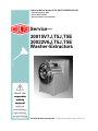
Service—
30015V7J,T5J,T5E
30022V6J,T5J,T5E
Washer-Extractors
PELLERIN MILNOR CORPORATION
POST OFFICE BOX 400, KENNER, LOUISIANA 70063-0400, U.S.A.
Please Read
About the Manual Identifying Information on the Cover
The front cover displays pertinent identifying information for this manual. Most important, are
the published manual number (part number) /ECN (date code). Generally, when a replacement
manual is furnished, it will have the same published manual number, but the latest available ECN.
This provides the user with the latest information applicable to his machine. Similarly all
documents comprising the manual will be the latest available as of the date the manual was
printed, even though older ECN dates for those documents may be listed in the table of
contents.
When communicating with the Milnor factory regarding this manual, please also provide the
other identifying information shown on the cover, including the publishing system, access date,
and whether the document ECN’s are the latest available or exact.
References to Yellow Troubleshooting Pages
This manual may contain references to “yellow pages.” Although the pages containing
troubleshooting procedures are no longer printed on yellow paper, troubleshooting instructions, if
any, will be contained in the easily located “Troubleshooting” chapter or section. See the table of
contents.
Trademarks of Pellerin Milnor Corporation
The following, some of which may be used in this manual, are trademarks of Pellerin Milnor
Corporation:
Ampsaver®
Autolint®
Auto-Purge®
Autovac
CBW®
Dye-Extractor®
Dyextractor®
E-P Express®
E-P OneTouch®
E-P Plus®
Gear Guardian®
Hands-Off®
Hydro-Cushion®
Mildata®
Milnet®
Milnor®
Miltrac
Miltron
Comments and Suggestions
Help us to improve this manual by sending your comments to:
Pellerin Milnor Corporation
Attn: Technical Publications
P. O. Box 400
Kenner, LA 70063-0400
Fax: (504) 469-1849
Staph-Guard®
System 4®
System 7®
Totaltrol®
Table of Contents
for MAP30VXXBE/2006145A
30015V7J,T5J,T5E 30022V6J,T5J,T5E Washer-Extractors
Page
Description
Document/ECN
1
3
4
9
11
16
BMP720097/92732A
25
Warranty
How to Order Parts
Safety—Rigid Washer Extractors
About the Forces Transmitted by Milnor Washer-Extractors
Glossary of Tag Illustrations-30" G, T and V style WE
Avoiding Damage from Allied Remote Chemical
Delivery Systems
Safety Placard Use and Placement 30015, 30022Txx
& Vxx
Safety Placard Use and Placement ISO 30015,
30022Txx & Vxx
Guards and Covers 30015V7J,T5J,T5E 30022V6J,T5J,T5E
27
Section 1: Service and Maintenance
21
23
28
32
Preventive Maintenance
Fastener Torque Requirements
51
Section 2: Drive Assemblies
52
53
54
57
58
60
62
Drive Chart 30015T5J,T5E & 30015T5J,T5E
Drive Chart 30015V7J, 30022V6J
Motor Mount 30015, 30022,36026, & 42026Vxx,Txx
Cylinder, Shell, Bearing, and Console Installation
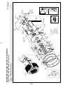
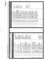
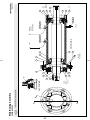
Main Bearing Assembly 30015V7J,T5J,T5E,M6x
Main Bearing Assembly 30020 & 30022
Section 4: Shell and Door Assemblies
66
68
70
Shellfront Assembly, Conduit, & Interlock
Door Assembly
Interlock Assembly
73
Section 5: Chemical Supply Devices
79
80
81
83
85
86
87
BIUUUS27/20051111
BIWUUI02/20001108
MSIUUMTGAE/2004072V
BIWUUI03/20030306
BMP020103/2002145V
BMP020104/2002145V
BMP000012/2001036V
BIRQUM01/20050302
MSSM0101CE/9906AV
BMP000006/2001036V
BMP000007/2000455V
BMP000008/2001036V
Section 3: Bearing Assemblies
65
74
75
76
BMP720097R/72332A
Soap Chute Installation
Peristaltic Supply Box
3 Compartment Supply Injector
BMP910037/2001036V
BMP910034/2001036V
BMP910033/2002446V
BMP920024/2004055V
BMP920009/2001036V
BMP750046/2001036V
BMP000040/2004055V
BMP000046/2004055V
BMP770149/2000333V
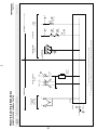
Section 6: Water and Steam Piping and
Assemblies
Schematic Symbols Key
Water, Steam and Drain Schematics
Water Inlet Assemblies with Peristaltic Supply
Level Switches
1/2" & 3/4" Hayes Electric Steam Valves
2-Way Electric Water Valve
BMP920008/2000302V
BMP000049/2002044V
BMP000047/2003215V
BMP000069/2001363V
BMP920028/2000302V
BMP920029/98443V
Table of Contents, cont.
Page
89
90
92
Description
Drain Sump Installation
Drain Valve Installation
3" Electric Drain Valve
Document/ECN
BMP920014/2004055V
BMP920020/2001036V
BMP920017/2002044V
3(//(5,10,/125&25325$7,21
/,0,7('67$1'$5':$55$17<
We warrant to the original purchaser that MILNOR machines including electronic
hardware/software (hereafter referred to as “equipment”), will be free from defects in material
and workmanship for a period of one year from the date of shipment from our factory with no
operating hour limitation. This warranty is contingent upon the equipment being installed,
operated and serviced as specified in the operating manual supplied with the equipment, and
operated under normal conditions by competent operators.
Providing we receive written notification of a warranted defect within 30 days of its discovery,
we will – at our option – repair or replace the defective part or parts, FOB our factory. We
retain the right to require inspection of the parts claimed defective in our factory prior to
repairing or replacing same. We will not be responsible, or in any way liable, for unauthorized
repairs or service to our equipment, and this warranty shall be void if the equipment is repaired
or altered in any way without MILNOR’s written consent.
Parts which require routine replacement due to normal wear – such as gaskets, contact points,
brake and clutch linings and similar parts – are not covered by this warranty, nor are parts
damaged by exposure to weather or to chemicals.
We reserve the right to make changes in the design and/or construction of our equipment
(including purchased components) without obligation to change any equipment previously
supplied.
ANY SALE OR FURNISHING OF ANY EQUIPMENT BY MILNOR IS MADE ONLY UPON
THE EXPRESS UNDERSTANDING THAT MILNOR MAKES NO EXPRESSED OR IMPLIED
WARRANTIES OF MERCHANTABILITY OR FITNESS FOR ANY PARTICULAR USE OR
PURPOSE. MILNOR WILL NOT BE RESPONSIBLE FOR ANY COSTS OR DAMAGES
ACTUALLY INCURRED OR REQUIRED AS A RESULT OF: THE FAILURE OF ANY OTHER
PERSON OR ENTITY TO PERFORM ITS RESPONSIBILITIES, FIRE OR OTHER HAZARD,
ACCIDENT, IMPROPER STORAGE, MISUSE, NEGLECT, POWER OR ENVIRONMENTAL
CONTROL MALFUNCTIONS, DAMAGE FROM LIQUIDS, OR ANY OTHER CAUSE BEYOND
THE NORMAL RANGE OF USE. REGARDLESS OF HOW CAUSED, IN NO EVENT SHALL
MILNOR BE LIABLE FOR SPECIAL, INDIRECT, PUNITIVE, LIQUIDATED, OR
CONSEQUENTIAL COSTS OR DAMAGES, OR ANY COSTS OR DAMAGES WHATSOEVER
WHICH EXCEED THE PRICE PAID TO MILNOR FOR THE EQUIPMENT IT SELLS OR
FURNISHES.
WE NEITHER ASSUME, NOR AUTHORIZE ANY EMPLOYEE OR OTHER PERSON TO
ASSUME FOR US, ANY OTHER RESPONSIBILITY AND/OR LIABILITY IN CONNECTION
WITH THE SALE OR FURNISHING OF OUR EQUIPMENT TO ANY BUYER.
BMP720097
92732A
1
2
How to order repair parts
Repair parts may be ordered either from the authorized dealer who sold you this
machine, or directly from the MILNOR factory. In most cases, your dealer will
have these parts in stock.
When ordering parts, please be sure to give us the following information:
1. Model and serial number of the machine for which the parts are required
2.
Part number
3. Name of the part
4. Quantity needed
5. Method of shipment desired
6. In correspondence regarding motors or electrical controls, please include all
nameplate data, including wiring diagram number and the make or
manufacturer of the motor or controls.
All parts will be shipped C.O.D. transportation charges collect only.
Please read this manual
It is strongly recommended that you read the installation and operating manual
before attempting to install or operate your machine. We suggest that this manual
be kept in your business office so that it will not become lost.
PELLERIN MILNOR CORPORATION
32%2;.(11(5/$86$
FAX: Administration 504/468-9307, Engineering 504/469-1849, Service 504/469-9777
BMP720097R
72332A
3
Safety—Rigid Washer Extractors
BIUUUS27 (Published) Book specs- Dates: 20051111 / 20051111 / 20060322 Lang: ENG01 Applic: RUU
Safety—Rigid Washer Extractors
1.
General Safety Requirements—Vital Information for
Management Personnel [Document BIUUUS04]
Incorrect installation, neglected preventive maintenance, abuse, and/or improper repairs, or
changes to the machine can cause unsafe operation and personal injuries, such as multiple
fractures, amputations, or death. The owner or his selected representative (owner/user) is
responsible for understanding and ensuring the proper operation and maintenance of the machine.
The owner/user must familiarize himself with the contents of all machine instruction manuals.
The owner/user should direct any questions about these instructions to a Milnor® dealer or the
Milnor® Service department.
Most regulatory authorities (including OSHA in the USA and CE in Europe) hold the owner/user
ultimately responsible for maintaining a safe working environment. Therefore, the owner/user
must do or ensure the following:
• recognize all foreseeable safety hazards within his facility and take actions to protect his
personnel, equipment, and facility;
• work equipment is suitable, properly adapted, can be used without risks to health or safety,
and is adequately maintained;
• where specific hazards are likely to be involved, access to the equipment is restricted to those
employees given the task of using it;
• only specifically designated workers carry out repairs, modifications, maintenance, or
servicing;
• information, instruction, and training is provided;
• workers and/or their representatives are consulted.
Work equipment must comply with the requirements listed below. The owner/user must verify
that installation and maintenance of equipment is performed in such a way as to support these
requirements:
• control devices must be visible, identifiable, and marked; be located outside dangerous zones;
and not give rise to a hazard due to unintentional operation;
• control systems must be safe and breakdown/damage must not result in danger;
• work equipment is to be stabilized;
• protection against rupture or disintegration of work equipment;
• guarding, to prevent access to danger zones or to stop movements of dangerous parts before
the danger zones are reached. Guards to be robust; not give rise to any additional hazards; not
be easily removed or rendered inoperative; situated at a sufficient distance from the danger
zone; not restrict view of operating cycle; allow fitting, replacing, or maintenance by
restricting access to relevant area and without removal of guard/protection device;
• suitable lighting for working and maintenance areas;
• maintenance to be possible when work equipment is shut down. If not possible, then
protection measures to be carried out outside danger zones;
• work equipment must be appropriate for preventing the risk of fire or overheating; discharges
of gas, dust, liquid, vapor, other substances; explosion of the equipment or substances in it.
PELLERIN MILNOR CORPORATION
4
Safety—Rigid Washer Extractors
1.1.
Laundry Facility—Provide a supporting floor that is strong and rigid enough to support–with
a reasonable safety factor and without undue or objectionable deflection–the weight of the fully
loaded machine and the forces transmitted by it during operation. Provide sufficient clearance for
machine movement. Provide any safety guards, fences, restraints, devices, and verbal and/or
posted restrictions necessary to prevent personnel, machines, or other moving machinery from
accessing the machine or its path. Provide adequate ventilation to carry away heat and vapors.
Ensure service connections to installed machines meet local and national safety standards,
especially regarding the electrical disconnect (see the National Electric Code). Prominently post
safety information, including signs showing the source of electrical disconnect.
1.2.
Personnel—Inform personnel about hazard avoidance and the importance of care and
common sense. Provide personnel with the safety and operating instructions that apply to them.
Verify that personnel use proper safety and operating procedures. Verify that personnel
understand and abide by the warnings on the machine and precautions in the instruction manuals.
1.3.
Safety Devices—Ensure that no one eliminates or disables any safety device on the machine
or in the facility. Do not allow machine to be used with any missing guard, cover, panel or door.
Service any failing or malfunctioning device before operating the machine.
1.4.
Hazard Information—Important information on hazards is provided on the machine safety
placards, in the Safety Guide, and throughout the other machine manuals. Placards must be kept
clean so that the information is not obscured. They must be replaced immediately if lost or
damaged. The Safety Guide and other machine manuals must be available at all times to
the appropriate personnel. See the machine service manual for safety placard part numbers.
Contact the Milnor Parts department for replacement placards or manuals.
1.5.
2.
Maintenance—Ensure the machine is inspected and serviced in accordance with the norms of
good practice and with the preventive maintenance schedule. Replace belts, pulleys, brake
shoes/disks, clutch plates/tires, rollers, seals, alignment guides, etc. before they are severely
worn. Immediately investigate any evidence of impending failure and make needed repairs (e.g.,
cylinder, shell, or frame cracks; drive components such as motors, gear boxes, bearings, etc.,
whining, grinding, smoking, or becoming abnormally hot; bending or cracking of cylinder, shell,
frame, etc.; leaking seals, hoses, valves, etc.) Do not permit service or maintenance by
unqualified personnel.
Safety Alert Messages—Internal Electrical and Mechanical
Hazards [Document BIUUUS11]
The following are instructions about hazards inside the machine and in electrical enclosures.
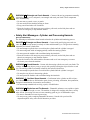
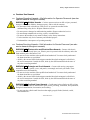
WARNING 1 : Electrocution and Electrical Burn Hazards—Contact with electric power
can kill or seriously injure you. Electric power is present inside the cabinetry unless the main
machine power disconnect is off.
• Do not unlock or open electric box doors.
• Do not remove guards, covers, or panels.
• Do not reach into the machine housing or frame.
• Keep yourself and others off of machine.
• Know the location of the main machine disconnect and use it in an emergency to remove
all electric power from the machine.
PELLERIN MILNOR CORPORATION
5
Safety—Rigid Washer Extractors
WARNING 2 : Entangle and Crush Hazards—Contact with moving components normally
isolated by guards, covers, and panels, can entangle and crush your limbs. These components
move automatically.
• Do not remove guards, covers, or panels.
• Do not reach into the machine housing or frame.
• Keep yourself and others off of machine.
• Know the location of all emergency stop switches, pull cords, and/or kick plates and use
them in an emergency to stop machine motion.
3.
Safety Alert Messages—Cylinder and Processing Hazards
[Document BIUUUS13]
The following are instructions about hazards related to the cylinder and laundering process.
DANGER 3 : Entangle and Sever Hazards—Contact with goods being processed can
cause the goods to wrap around your body or limbs and dismember you. The goods are normally
isolated by the locked cylinder door.
• Do not attempt to open the door or reach into the cylinder until the cylinder is stopped.
• Do not touch goods inside or hanging partially outside the turning cylinder.
• Do not operate the machine with a malfunctioning door interlock.
• Know the location of all emergency stop switches, pull cords, and/or kick plates and use
them in an emergency to stop machine motion.
• Know the location of the main machine disconnect and use it in an emergency to remove
all electric power from the machine.
WARNING 4 : Crush Hazards—Contact with the turning cylinder can crush your limbs. The
cylinder will repel any object you try to stop it with, possibly causing the object to strike or stab
you. The turning cylinder is normally isolated by the locked cylinder door.
• Do not attempt to open the door or reach into the cylinder until the cylinder is stopped.
• Do not place any object in the turning cylinder.
• Do not operate the machine with a malfunctioning door interlock.
WARNING 5 : Confined Space Hazards—Confinement in the cylinder can kill or injure
you. Hazards include but are not limited to panic, burns, poisoning, suffocation, heat prostration,
biological contamination, electrocution, and crushing.
• Do not attempt unauthorized servicing, repairs, or modification.
WARNING 6 : Explosion and Fire Hazards—Flammable substances can explode or ignite
in the cylinder, drain trough, or sewer. The machine is designed for washing with water, not any
other solvent. Processing can cause solvent-containing goods to give off flammable vapors.
• Do not use flammable solvents in processing.
• Do not process goods containing flammable substances. Consult with your local fire
department/public safety office and all insurance providers.
PELLERIN MILNOR CORPORATION
6
Safety—Rigid Washer Extractors
4.
4.1.
4.1.1.
Safety Alert Messages—Unsafe Conditions [Document BIUUUS14]
Damage and Malfunction Hazards
Hazards Resulting from Inoperative Safety Devices
DANGER 7 : Entangle and Sever Hazards—Cylinder door interlock—Operating the
machine with a malfunctioning door interlock can permit opening the door when the cylinder is
turning and/or starting the cycle with the door open, exposing the turning cylinder.
• Do not operate the machine with any evidence of damage or malfunction.
WARNING 8 : Multiple Hazards—Operating the machine with an inoperative safety device
can kill or injure personnel, damage or destroy the machine, damage property, and/or void the
warranty.
• Do not tamper with or disable any safety device or operate the machine with a
malfunctioning safety device. Request authorized service.
WARNING 9 : Electrocution and Electrical Burn Hazards—Electric box doors—
Operating the machine with any electric box door unlocked can expose high voltage conductors
inside the box.
• Do not unlock or open electric box doors.
WARNING 10 : Entangle and Crush Hazards—Guards, covers, and panels—Operating
the machine with any guard, cover, or panel removed exposes moving components.
• Do not remove guards, covers, or panels.
4.1.2.
Hazards Resulting from Damaged Mechanical Devices
WARNING 11 : Multiple Hazards—Operating a damaged machine can kill or injure
personnel, further damage or destroy the machine, damage property, and/or void the warranty.
• Do not operate a damaged or malfunctioning machine. Request authorized service.
WARNING 12 : Explosion Hazards—Cylinder—A damaged cylinder can rip apart during
extraction, puncturing the shell and discharging metal fragments at high speed.
• Do not operate the machine with any evidence of damage or malfunction.
WARNING 13 : Explosion Hazards—Clutch and speed switch (multiple motor
machines)—A damaged clutch or speed switch can permit the low speed motor to engage during
extract. This will over-speed the motor and pulleys and can cause them to rip apart, discharging
metal fragments at high speed.
• Stop the machine immediately if any of these conditions occur: • abnormal whining sound
during extract • skidding sound as extract ends • clutches remain engaged or re-engage
during extract
PELLERIN MILNOR CORPORATION
7
Safety—Rigid Washer Extractors
4.2.
4.2.1.
Careless Use Hazards
Careless Operation Hazards—Vital Information for Operator Personnel (see also
operator hazards throughout manual)
WARNING 14 : Multiple Hazards—Careless operator actions can kill or injure personnel,
damage or destroy the machine, damage property, and/or void the warranty.
• Do not tamper with or disable any safety device or operate the machine with a
malfunctioning safety device. Request authorized service.
• Do not operate a damaged or malfunctioning machine. Request authorized service.
• Do not attempt unauthorized servicing, repairs, or modification.
• Do not use the machine in any manner contrary to the factory instructions.
• Use the machine only for its customary and intended purpose.
• Understand the consequences of operating manually.
4.2.2.
Careless Servicing Hazards—Vital Information for Service Personnel (see also
service hazards throughout manuals)
WARNING 15 : Electrocution and Electrical Burn Hazards—Contact with electric
power can kill or seriously injure you. Electric power is present inside the cabinetry unless the
main machine power disconnect is off.
• Do not service the machine unless qualified and authorized. You must clearly understand
the hazards and how to avoid them.
• Abide by the current OSHA lockout/tagout standard when lockout/tagout is called for in
the service instructions. Outside the USA, abide by the OSHA standard in the absence of
any other overriding standard.
WARNING 16 : Entangle and Crush Hazards—Contact with moving components
normally isolated by guards, covers, and panels, can entangle and crush your limbs. These
components move automatically.
• Do not service the machine unless qualified and authorized. You must clearly understand
the hazards and how to avoid them.
• Abide by the current OSHA lockout/tagout standard when lockout/tagout is called for in
the service instructions. Outside the USA, abide by the OSHA standard in the absence of
any other overriding standard.
WARNING 17 : Confined Space Hazards—Confinement in the cylinder can kill or injure
you. Hazards include but are not limited to panic, burns, poisoning, suffocation, heat prostration,
biological contamination, electrocution, and crushing.
• Do not enter the cylinder until it has been thoroughly purged, flushed, drained, cooled,
and immobilized.
— End of BIUUUS27 —
PELLERIN MILNOR CORPORATION
8
About the Forces Transmitted by Milnor® Washer-extractors
About the Forces Transmitted by Milnor®
Washer-extractors
Document ..................... BIWUUI02
Specified Date ................. 20001108
As-of Date ....................... 20001108
Access Date ..................... 20001108
Applicability...........................WUU
During washing and extracting, all washer-extractors transmit both static and dynamic
(cyclic) forces to the floor, foundation, or any other supporting structure. During washing, the
impact of the goods as they drop imparts forces which are quite difficult to quantify. Size for size,
both rigid and flexibly-mounted machines transmit approximately the same forces during
washing. During extracting, rigid machines transmit forces up to 30 times greater than equivalent
flexibly-mounted models. The actual magnitude of these forces vary according to several factors:
•
•
•
•
•
machine size,
final extraction speed,
amount, condition, and type of goods being processed,
the liquor level and chemical conditions in the bath preceding extraction, and
other miscellaneous factors.
Estimates of the maximum force normally encountered are available for each Milnor® model
and size upon request. Floor or foundation sizes shown on any Milnor® document are only for
on-grade situations based only on previous experience without implying any warranty, obligation,
or responsibility on our part.
1.
Rigid Machines
Size for size, rigid washer-extractors naturally require a stronger, more rigid floor,
foundation, or other supporting structure than flexibly-mounted models. If the supporting soil
under the slab is itself strong and rigid enough and has not subsided to leave the floor slab
suspended without support, on grade installations can often be made directly to an existing floor
slab if it has enough strength and rigidity to safely withstand our published forces without
transmitting undue vibration. If the subsoil has subsided, or if the floor slab itself has insufficient
strength and rigidity, a deeper foundation, poured as to become monolithic with the floor slab,
may be required. Support pilings may even be required if the subsoil itself is “springy” (i.e., if its
resonant frequency is near the operating speed of the machine). Above-grade installations of rigid
machines also require a sufficiently strong and rigid floor or other supporting structure as
described below.
2.
Flexibly-mounted Machines
Size for size, flexibly-mounted machines generally do not require as strong a floor,
foundation, or other supporting structure as do rigid machines. However, a floor or other
supporting structure having sufficient strength and rigidity, as described in section 3, is
nonetheless vitally important for these models as well.
3.
How Strong and Rigid?
Many building codes in the U.S.A. specify that laundry floors must have a minimum live
load capacity of 150 pounds per square foot (732 kilograms per square meter). However, even
compliance with this or any other standard does not necessarily guarantee sufficient rigidity. In
any event, it is the sole responsibility of the owner/user to assure that the floor and/or any other
supporting structure exceeds not only all applicable building codes, but also that the floor and/or
any other supporting structure for each washer-extractor or group of washer-extractors actually
9
has sufficient strength and rigidity, plus a reasonable factor of safety for both, to support the
weight of all the fully loaded machine(s) including the weight of the water and goods, and
including the published 360º rotating sinusoidal RMS forces that are transmitted by the
machine(s). Moreover, the floor, foundation, or other supporting structure must have sufficient
rigidity (i.e., a natural or resonant frequency many times greater than the machine speed with a
reasonable factor of safety); otherwise, the mentioned 360º rotating sinusoidal RMS forces can be
multiplied and magnified many times. It is especially important to consider all potential vibration
problems that might occur due to all possible combinations of forcing frequencies (rotating
speeds) of the machine(s) compared to the natural frequencies of the floor and/or any other
supporting structure(s). A qualified soil and/or structural engineer must be engaged for this
purpose.
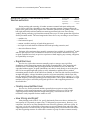
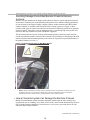
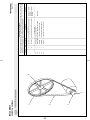
Figure 1: How Rotating Forces Act on the Foundation
Typical Machine
Legend
A.
B.
C.
Direction of force
Load
Rotation (Frequency = RPM / 60)
Figure 1 above is intended to depict both on-grade and above-grade installations and is
equally applicable to flexibly-mounted washer-extractors, as well as to rigid models installed
either directly on a floor slab or on a foundation poured integrally with the slab. Current machine
data is available from Milnor® upon request. All data is subject to change without notice and may
have changed since last printed. It is the sole responsibility of every potential owner to obtain
written confirmation that any data furnished by Milnor® applies for the model(s) and serial
number(s) of the specific machines.
— End of BIWUUI02 —
10
7\_ccQbi_VDQW9\\ecdbQdY_^c±
7Cdi\U# DCdi\U# FCdi\U
GQcXUb5hdbQSd_bc
Illustration
<B8DD<C604!#&!E
Explanation
Illustration
Explanation
Stop! Read the manual first for complete
instructions before continuing.
Do not start this machine until the packing
materials, lifting brackets, etc. with this tag
attached or behind this panel are removed.
These materials are painted red. Safety stands
or brackets (also painted red) may be provided
with this machine. Do not discard safety
stands or brackets
Do not jack the machine here.
Do not lift the machine here.
This motor or pump should rotate in the
direction of the arrow.
Do not start this machine until the part with
this tag is installed on the machine.
Use three point or four point lifting as
determined by the lifting eyes furnished. Rig
the load using lifting cables of sufficient size
and length to ensure cables are not
over-stressed.
Do not lift the machine from one corner or one
side edge.
11
Do not remove this component from the
machine.
7\_ccQbi_VDQW9\\ecdbQdY_^c±
7Cdi\U# DCdi\U# FCdi\U
GQcXUb5hdbQSd_bc
Illustration
<B8DD<C604!#&!E
Explanation
Illustration
Explanation
Stop! Read the manual first for complete
instructions before continuing.
Do not start this machine until the packing
materials, lifting brackets, etc. with this tag
attached or behind this panel are removed.
These materials are painted red. Safety stands
or brackets (also painted red) may be provided
with this machine. Do not discard safety
stands or brackets
Do not jack the machine here.
Do not lift the machine here.
This motor or pump should rotate in the
direction of the arrow.
Do not start this machine until the part with
this tag is installed on the machine.
Use three point or four point lifting as
determined by the lifting eyes furnished. Rig
the load using lifting cables of sufficient size
and length to ensure cables are not
over-stressed.
Do not remove this component from the
machine.
Do not lift the machine from one corner or one
side edge.
12
Illustration
Explanation
Illustration
Install the appropriate part here before
operating the machine.
Explanation
Make third (reuse) water connection here.
H20
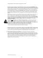
During drain and extract, the cylinder must
rotate counterclockwise when viewed from
here (rear of machine).
Make flushing water connection here.
Make cold water connection here.
H20
H20
Do not strike shell front of washer-extractors
during fork lifting. Striking shell front will
cause door to leak.
Make hot water connection here.
H20
Water hammer will rupture the water inlet
valves on this machine. Eliminate water
hammer on waterlines to this machine. Follow
all applicable codes when installing water
hammer arresters on water lines.
13
Illustration
Explanation
Illustration
Explanation
Install the appropriate part here before
operating the machine.
Make third (reuse) water connection here.
H20
During drain and extract, the cylinder must
rotate counterclockwise when viewed from
here (rear of machine).
Make flushing water connection here.
Make cold water connection here.
H20
H20
Do not strike shell front of washer-extractors
during fork lifting. Striking shell front will
cause door to leak.
Make hot water connection here.
H20
Water hammer will rupture the water inlet
valves on this machine. Eliminate water
hammer on waterlines to this machine. Follow
all applicable codes when installing water
hammer arresters on water lines.
14
Excessive water temperture will damage
valves. Do not exceed 160 degrees Fahrenheit
(71 degrees Celsius).
Fo
C
o
160 F°
71 C°
Excessive air pressure will damage valves.
Do not exceed 80 psi (5.5 bar).
10 - 75 psi
0.7 - 5.1 bar
15
BIWUUI03 (Published) Book specs- Dates: 20030306 / 20030306 / 20030306 Lang: ENG01 Applic: WUU
Avoiding Damage From Allied Remote Chemical Delivery
Systems
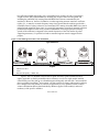
Milnor® does not manufacture or supply remote chemical delivery systems and this document is
meant only to illustrate some of the possible problems that can be minimized during installation
of such systems by the chemical supply company. Milnor washer-extractors and CBW® batch
washers (tunnels) are available with convenient inlets for such systems (see Figure 1). Most
common of the types of systems currently used in commercial laundering operations are pumped
chemical systems. Other types, such as constant pressure, re-circulating ring main systems have
also been, and may continue to be used with Milnor equipment.
This document warns about some of the possible hazards posed by chemical systems and lists
certain requirements needed to minimize those hazards. The procedures for interfacing with allied
chemical systems and information pertinent to chemical use in general are provided elsewhere in
the product manuals (see Note 1).
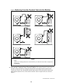
Figure 1: Pumped Chemical Inlets on CBW Batch Washer
Note 1: Misuse of laundering chemicals (such as injecting excessive concentrations of chlorine bleach or
permitting acid sours to react with hypo chlorite) due to incorrect formulation can also be hazardous.
Information pertinent to chemical use is provided elsewhere in the product manuals.
1.
How a Chemical System Can Damage the Machine It Serves
Milnor has manufactured washer-extractors and tunnel washers with the same stainless steel
specification since its founding. Every batch of steel used is certified and documented by the steel
mill. Testing of samples damaged by corrosion have, in every case, proven the steel to be well
within the AISI 304 specification.
PELLERIN MILNOR CORPORATION
16
Avoiding Damage From Allied Remote Chemical Delivery Systems
Chemical products commonly found in the laundry industry, when used in established dosages
and proper operating parameters, under the auspices of an experienced chemical specialist, should
produce satisfactory results, with no consequential detrimental effects. The industry has published
standards in Riggs and Sherrill, “Textile Laundering Technology”. However, the stainless steel
can be damaged and even destroyed by abnormal contact with chlorine bleach, hydrofluosilicic
acid and other commonly used chemicals, as will occur if chemicals are unintentionally leaked
into the machine, particularly when it is no longer in use and especially when machine surfaces
are dry.
Some chemical systems have been found to permit chemicals to dribble from the supply lines, or
worse, to siphon from the supply tank into the machine, during operation and long after the
system is shut down—as after working hours and during weekends. If this occurs, deterioration
(rusting) of the stainless steel and damage to any textiles therein will inevitably result. If this
condition goes undetected, machine damage is likely to be catastrophic. No machine is
immune to such damage.
CAUTION 1 : Equipment and Textile Damage Hazards—Chemicals leaked into the
machine, particularly when it is idle can destroy machine components and textiles left in the
machine. Pellerin Milnor Corporation accepts absolutely no responsibility for damage to its
equipment or to textiles therein from abnormal contact with chemicals.
• Ensure that the chemical system prevents unintentional release of chemicals.
• Inspect regularly for proper operation and evidence of damage.
2.
Requirements for Chemical Systems Used With Milnor Machines
It is the responsibility of the chemical system manufacturer and supplier to ensure that their
system is safe for personnel and equipment. Some important points are described below.
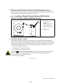
2.1.
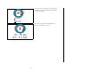
Ensure the System Cannot Siphon.—The supply system must be designed to
counteract any siphoning that could occur as a result of having a sealed supply line between the
bottom of the chemical tank and the internal machine connection at the drain trough. As shown in
the Figure 2 examples, if the pump (P) and/or the valving does not provide positive closure and
there is no vacuum breaker protection, siphoning is likely to occur. In each of the Figure 2
illustrations, the volume of chemical in the tank above the siphon level (S), and indicated by
shading, will flow into the machine.
PELLERIN MILNOR CORPORATION
17
Figure 2: Siphoning
From the Chemical Tank into the Machine
Examples
Legend
P.
S.
T.
2.2.
Pump
Siphon level. Shading indicates the chemical delivery line and tank content that can siphon into
the machine.
Chemical tank
Ensure the Chemical Lines Cannot Dribble—The pumped chemical system may
provide a means of positively closing the chemical line at the pump location, but not at the
injection site. Hence, any concentrated chemical that remains in the injection line between the
pump and the machine is free to flow into the machine. Some examples of this are shown in
Figure 3.
PELLERIN MILNOR CORPORATION
18
Avoiding Damage From Allied Remote Chemical Delivery Systems
Figure 3: Dribbling
From Chemical Supply Line Into Machine
(assumes positive closure at the pump)
Examples
Legend
D.
P.
T.
3.
Portion of supply line, the contents of which can dribble into the machine
Pump
Chemical tank
Design and Installation Recommendations
It is the responsibility of the chemical system manufacturer and supplier to use whatever
measures are necessary to ensure that their system is safe for personnel and equipment. The
following are some of the possible methods the manufacturer or supplier may wish to use, as
appropriate.
3.1.
Siphoning: Positively close the line.—If the pump does not provide positive closure
when the system is off, employ a shutoff valve in the line to serve this purpose.
3.2.
Siphoning: Break the siphon.—Provide an air gap or vacuum breaker in the chemical
delivery line. This must be located above the “full” line of the tank.
3.3.
Dribbling: Flush the entire chemical delivery line.—If any concentrated chemical
that remains in the injection line between the pump and the machine is free to flow into the
machine, employ a system that flushes the entire line between the pump and the injection point
with fresh water after each injection.
PELLERIN MILNOR CORPORATION
19
3.4.
Dribbling: Locate the entire chemical line below the machine inlet.—
Assuming the chemical system does not retain any line pressure and that the pump provides
positive closure when the system is off, locate the entire chemical delivery line below the level of
the chemical inlet. An example of this is shown in Figure 4.
Figure 4: Locating
a Pumped Chemical System With Positive
Closure To Protect Against Machine Damage
Example of Correct Placement
Legend
I.
L.
P.
T.
4.
Chemical inlet on
machine
Chemical delivery line
Pump with positive
closure when system is
off
Chemical tank
Guarding Against Leaks
All personnel who may work with the chemical system (e.g., chemical system manufacturer,
chemical system supplier, chemical supplier, operator, maintenance personnel) should be vigilant
in observing for leaks in the system. When connecting, or reconnecting chemical lines, whether at
installation, after taking samples, or when replacing components, at a minimum ensure that:
1. the proper components are used,
2. all connections are the proper fit, and
3. all components are securely connected.
CAUTION 2 : Injury and Damage Hazards—Chemicals leaking from a chemical system
may be corrosive or toxic. Such chemicals can injure personnel and damage equipment.
• Use care when connecting chemical lines.
• Inspect regularly for leaks.
— End of BIWUUI03 —
PELLERIN MILNOR CORPORATION
20
21
P. O. Box 400, Kenner, LA 70063-0400
Pellerin Milnor Corporation
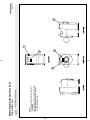
LEFT VIEW
Notes:
1. Replace placard immediately, if removed or
unreadable.
2. Approximate locations of placards are shown.
Mounting holes are provided on machine.
Use #8 self-tapping screws.
R
30015, 30022Txx & Vxx
Safety Placard Use and Placement
50
FRONT VIEW
REAR VIEW
10
40
30
RIGHT VIEW
20
Litho in U.S.A.
BMP020103/2002145V
(Sheet 1 of 2)
BMP020103/2002145V
(Sheet 2 of 2)
R
Pellerin Milnor Corporation
P. O. Box 400, Kenner, LA 70063-0400
Litho in U.S.A.
Parts List—Safety Placard Placement
Find the correct assembly first, then find the needed components. The item letters (A, B, C, etc.) assigned to
assemblies are referred to in the "Used In" column to identify which components belong to an assembly. The item
numbers (1, 2, 3, etc.) assigned to components relate the parts list to the illustration.
Description
Item Part Number
Comments
. Used In
.
---------------------------------------------------------------------ASSEMBLIES-----------------------------------------------------------------none
-------------------------------------------------------------------COMPONENTS-----------------------------------------------------------------all
10
01 10635A
NPLT:SHELL FORNT RIDGID-TCATA
all
20
01 10375B
NPLT:ELEC HAZARD SMALL-TCATA
all
30
01 10375C
NPLT:E-HAZARD SM VERTCL-TCATA
all
40
01 10689A
NPLT:BELT HAZARD SM TCATA
all
50
01 10699A
NPLT:SERV HZRD-PLYEST-TCATA
22
23
R
Notes:
1. Replace placard immediately, if removed
or unreadable.
2. Approximate locations
of placards are shown.
Mounting holes are
provided on machine.
If aluminum placard
use #8 self-tapping
screws.
LEFT VIEW
ISO Placards
shown on this page
P. O. Box 400, Kenner, LA 70063-0400
Pellerin Milnor Corporation
30015, 30022Txx & Vxx
Safety Placard Use and Placement ISO
10
FRONT VIEW
REAR VIEW
30
RIGHT VIEW
20
Litho in U.S.A.
BMP020104/2002145V
(Sheet 1 of 2)
BMP020104/2002145V
(Sheet 2 of 2)
R
Pellerin Milnor Corporation
P. O. Box 400, Kenner, LA 70063-0400
Litho in U.S.A.
Parts List—Safety Placard Placement
Find the correct assembly first, then find the needed components. The item letters (A, B, C, etc.) assigned to
assemblies are referred to in the "Used In" column to identify which components belong to an assembly. The item
numbers (1, 2, 3, etc.) assigned to components relate the parts list to the illustration.
Description
Item Part Number
Comments
Used In
.
---------------------------------------------------------------------ASSEMBLIES-----------------------------------------------------------------none
-------------------------------------------------------------------COMPONENTS-----------------------------------------------------------------all
10
01 10635X
NPLT:30"WE RIGID WARNING ISO
all
20
01 10375A
NPLT:VDE VOLTAGE WARN 1.25"
all
30
01 10375
NPLTE:"WARNING" 2X2
24
25
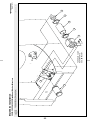
R
P. O. Box 400, Kenner, LA 70063-0400
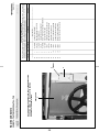
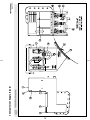
Pellerin Milnor Corporation
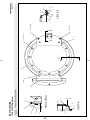
30015V7J, T5J,T5E 30022V6J, T5J, T5E
Guards and Covers
1
2
5
3
10,11
4 PLACES
10,11
6 PLACES
12
2 PLACES
4
7,8,9
4 PLACES
Litho in U.S.A.
BMP000012/2001036V
(Sheet 1 of 2)
26
R
DUST COVER
6
NOTE: KEEP DUST COVER IN PLACE AT ALL TIMES. REMOVE FOR
SERVICING. BEHIND THIS COVER ARE THE BEARING
HOUSING FILL AND DRAIN TUBES.
P. O. Box 400, Kenner, LA 70063-0400
Pellerin Milnor Corporation
30015V7J, T5J,T5E 30022V6J, T5J, T5E
Guards and Covers
4
13
TYPICAL
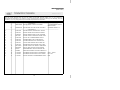
Parts List—Guards and Covers
Item
Part Number
Description
Comments
11
12
14
all
all
all
7
all
10
6
all
all
5
all
9
4
all
all
3
all
8
2
all
all
1
all
15P010
15P185
15U346
15P200
17N070P
02 03344
15K120
03 C1824V
W2-03795B
03 C4X7
X2 03497A
02 03344
W2 03699A
PHILPAN TRDCUTSCRTYP10-24X1/2S
TRDCUT-F HXHD 1/4-20UNC2AX3/4
FLAWASH 7/8X3/8X.030 NATURAL N
TRDCUT-F HXWASHD 3/8-16X3/4NIK
RETAIN NUT 3/8-16 #S10100-27
TRIM=REAR CONSOLE TOP 7FT/PC
HXCAPSCR 3/8-16UNC2AX2 GR5 ZIN
DUST COVER-30"V6J BELT
00342# *WLMT=LOWER COVER-STEAM F0141
COVER:SYSTEM 7 LIQUID SUPPLY
GUARD REAR BELT
TRIM=REAR CONSOLE TOP 7FT/PC
*CONSOLE TOP WELDMENT
-------------------------------------------------------------------COMPONENTS------------------------------------------------------------------
. Used In
Find the correct assembly first, then find the needed components. The item letters (A, B, C, etc.) assigned to
assemblies are referred to in the "Used In" column to identify which components belong to an assembly. The item
numbers (1, 2, 3, etc.) assigned to components relate the parts list to the illustration.
Litho in U.S.A.
BMP000012/2001036V
(Sheet 2 of 2)
Section
Service and Maintenance
27
1
Preventive Maintenance
BIRQUM01 (Published) Book specs- Dates: 20050302 / 20050302 / 20050302 Lang: ENG01 Applic: RMV
Preventive Maintenance
1.
Lubrication Guidelines
As required by the warranty, to ensure safe operation, and to achieve optimum performance and
service life from Milnor® washer-extractors, the schedules, instructions, and precautions herein
must be strictly followed.
WARNING 1 : Entangle and Crush Hazard—Belts and pulleys can entangle and crush
body parts.
• Lock OFF and tag out power at the wall disconnect before servicing, except where
specifically instructed otherwise in this section.
• Insure belt and pulley guards are in place during service procedures.
• Permit only qualified maintenance personnel to perform these procedures.
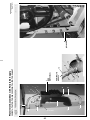
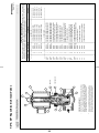
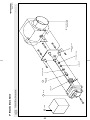
2.
30022C4x, 30022T5x and 30022V6J Main Bearing Maintenance
30022C4x, 30022T5x and 30022V6J main bearing housings are oil-filled and require periodic
draining and refilling (see below).
See the appropriate “MAIN BEARING ASSEMBLY” (see Table of Contents) during this
procedure.
1. Remove the drain plug on the bottom of the main bearing housing and allow the bearing
housing to drain completely (Figure 1). Inspect the leak-off, drained oil, and magnetic drain
plug for water and/or metal particles. Install the drain plug. Water and/or metal particles can
indicate worn or damaged seals and bearings.
2. Locate the two 1/2" plastic tubes secured to the electrical control chassis. Clean the
surrounding area and remove the cork stoppers from each (Figure 2).
3. Strictly following lubrication specifications, refill the bearing housing. After refilling the
bearing housing, re-install the cork stoppers and clean any excess lubricant from the machine.
PELLERIN MILNOR CORPORATION
28
Preventive Maintenance
Preventive Maintenance Schedule
3.
Table 1: Preventive Maintenance Checklist
Component
Action
Frequency
Specifications/Figure
High quality SAE 30 to 50
(ISO 100 - 220) single weight
heavy duty motor oil (nondetergent if available). See
"Oil Drain and Water Leakoff" and also see
"30022C4x,..Fill/Vent Hoses"
See "Drive Train Pulleys and
Belts"
See motor nameplate. If not
specified, use Shell Alvania
(or equivalent). See "Motor
Grease Points"
See "Inverter Maintenance
Points"
Bearing
Housing
Oil
Remove fill, vent and drain
stoppers. Refill 22 ounces (634
grams)
Every four
months
Drive Train
Belts and pulleys
Check for wear, replace as
required
See "Baldor Motor
Maintenance...," in this manual
(See Note 3)
Monthly
Verify fan operation. Vacuum
out inverter vents.
Check for leaks, cracks and
bulges
Monthly
Check bolt tightness and wear
Monthly
Drive
Inverter
Hoses,
Clamps, and
Connections
Bolts
Motors (if
equipped with
grease fittings)
(See Note 2)
Inverter
Inlet, drain, and
chemical hoses
and connections
Foundation
Rear bearing
reinforcement
plate and
throughout
machine
Every three
Months
Monthly
See dimensional drawings
See "30022C4x,...Rear
Reinforcement Plate" for
36021C4E and 36026V5J
machines, or "42026V6J Rear
Reinforcement Plate" for
42026V6J machines.
Note 1: Monthly/200 hours = Once a month or once every 200 operating hours, whichever comes first.
Note 2: Do not over-lubricate motors. Over-lubrication of a motor can seriously damage it by forcing
grease into motor windings.
Note 3: If motor manufacturer's instructions conflict with manual section MSSM0274AE, follow
manufacturers instructions. Motors are warranted by the manufacturers, not by Milnor.
PELLERIN MILNOR CORPORATION
29
Preventive Maintenance
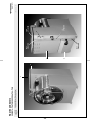
4.
Maintenance Points
Figure 1: 30022C4x, 30022T5x, 36021C4E and
36026V5J Oil Drain and Water Leak-off
Figure 2: 30022C4x, 30022T5x,
36021C4E and 36026V5J Oil
Fill/Vent Hoses (use either hose
for filling)
Figure 3: Drive Train Pulleys and
Belts (30022V6J shown)
PELLERIN MILNOR CORPORATION
30
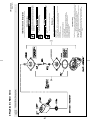
Preventive Maintenance
Figure 4: Inverter Maintenance Points
30022C4x, 30022T5x and
30022V6J Inverter
Legend
1.
2.
Fan
Vent
.
Figure 5: 30022C4x, 30022T5x, 30022V6J,
36021C4E and 36026V5J Rear Bearing
Reinforcement Plate (30022VxJ shown)
— End of BIRQUM01 —
PELLERIN MILNOR CORPORATION
31
MSSM0101CE/9906AV (1 of 19)
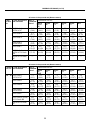
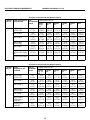
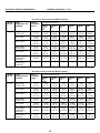
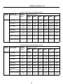
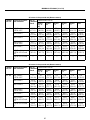
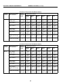
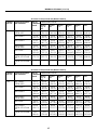
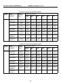
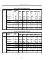
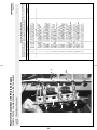
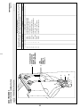
FASTENER TORQUE REQUIREMENTS
È
The specifications in this section apply to 1/4 inch and larger Unified National fine and coarse fasteners used on
Milnor® machines. This information is to be used only when torque specifications are not stated in the installation
or service instructions.
When tightening applicable fastener, abide by the following precautions:
1. Always use new fasteners. Replace bolts, nuts, flat washers, and lock washers in the order shown on the parts
drawing.
2. Unless otherwise specified, use:
Loctite® 271 threadlocker or equivalent for bearing
housing mounting bolts from one half to one inch in diameter.
•
•
Loctite® 277 threadlocker or equivalent for bearing
housing mounting bolts of one inch diameter or larger.
•
Loctite® 242 threadlocker for all other fasteners
requiring thread locking compound.
3. Use a torque wrench to assure proper tightness.
4. Never lubricate fasteners. The values specified herein are
maximum recommended torques and are calculated from
published ASTM and SAE data. Actual allowable torques
are application dependent and can vary for many reasons,
(joint types, gaskets, etc.). Use these values as a guide.
ÎFIGURE 1 (MSSM0101CE)
ÎFastener Grade Markings
5. Although FIGURE 1 depicts hex head bolts, the table applies to all head types.
Fasteners and Threadlocker
Ê
How Fasteners Loosen—Standard threaded fasteners are manufactured with a clearance fit for easy assemË
bly. With the fastener at the proper torque, 85% of the tightening torque is absorbed in the threads and under the
fastener head. The remaining 15% provides the friction that prevents the thread from slipping. When this friction is
overcome (by bending, thermal expansion, internal pressures, functional loads, or impact) the thread slips and loosens. Although higher torques reduce the likelihood of thread slippage, if slippage occurs, the threads unwind and
the fastener loosens. Once thread slippage begins, vibration increases the rate of loosening.
Preventing Loosening—The most effective way to prevent loosening of threaded parts is by proper appliË
cation of a threadlocking compound. Threadlocker provides lubrication during assembly, then hardens to seal the
threads against corrosion and provide resistance to thread slippage.
32
MSSM0101CE/9906AV (2 of 19)
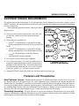
Applying Threadlocker
Ê
NOTE: The following threadlocker information and
illustrations are excerpts from the Loctite® User’s
Guide and are used with permission.
For maximum strength, threadlocker must fill the thread
voids completely, as shown in FIGURE 2. Organic or petroleum solvent will remove excess uncured adhesive from
joints. Consult information below for the specific fastener application.
ÎFIGURE 2 (MSSM0101CE)
ÎCorrect Threadlocker Use
Bolts and Nuts—See FIGURE 3.
Ë
1. Clean all threads (bolt and nut) with cleaning solvent.
Apply here
2. Spray all threads with Loctite® Primer N. Allow to dry.
3. Insert bolt into through hole assembly.
4. Apply several drops of threadlocker onto bolt engagement area.
5. Assemble and tighten nut to correct torque for the
threadlocker.
Blind Holes—See FIGURE 4.
Ë
Not here
1. Clean all threads (bolt and nut) with cleaning solvent.
2. Spray all threads with Loctite® Primer N. Allow to dry.
ÎFIGURE 3 (MSSM0101CE)
ÎApplying Threadlocker to
Through Hole
3. Squirt several drops down female threads into bottom of
hole.
Onto
threads
4. Apply several drops to bolt.
5. Tighten to correct torque for the threadlocker.
Onto
threads
ÎFIGURE 4 (MSSM0101CE)
ÎApplying Threadlocker to Blind Holes
33
FASTENER TORQUE REQUIREMENTS
MSSM0101CE/9906AV (3 of 19)
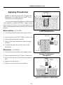
Removing Fasteners
Ë
High strength threadlockers like Loctite® 271 (or equivalent)
may be weakened by heating to at least 500o F (260o C) as
follows.
1. Apply localized heat to fastener as shown in FIGURE 5.
2. Disassemble while hot. Once disassembled, the cured adhesive can be removed with Loctite® Gasket Remover
#790 (or equivalent).
ÎFIGURE 5 (MSSM0101CE)
ÎRemoving High Strength Threadlocker
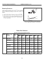
ÏCarbon Steel Fasteners
Ï ll values in foot pounds and (Newton meters)
A
Nominal Grade
bolt size Designation and
Standard
1/4 - 20
Zinc or
If instructions call for :
Cadmium
Loctite
Loctite
Loctite
Plated
222 or
242
271
262
Loctite
272
Loctite
277
Bare
SAE Grade 1
ASTM A307
2.5
(3.39)
3.0
(4.06)
3.3
(4.47)
3.6
(4.88)
4.6
(6.23)
4.3
(5.83)
3.3
(4.47)
SAE Grade 2
4.1
(5.56)
4.9
(6.64)
5.5
(7.45)
6.0
(8.13)
7.7
(10.44)
7.1
(9.63)
5.5
(7.46)
SAE Grade 4
4.8
(6.50)
5.8
(7.86)
6.4
(8.67)
7.0
(9.49)
9.0
(12.20)
8.3
(11.25)
6.4
(8.67)
SAE Grade 5
ASTM A449
6.3
(8.54)
7.6
(10.3)
8.4
(11.38)
9.3
(12.60)
11.8
(15.99)
11.0
(14.91)
8.4
(11.39)
SAE Grade 7
7.9
(10.7)
9.4
(12.7)
10.5
(14.23)
11.5
(15.59)
14.7
(19.93)
13.6
(18.44)
10.5
(14.23)
SAE Grade 8
ASTM A354 Grade
BD
8.9
(12.0)
10.7
(14.5)
11.9
(16.13)
13.1
(17.76)
16.6
(22.50)
15.4
(20.88)
11.9
(16.13)
ASTM A354 Grade
BC
7.9
(10.7)
9.4
(12.7)
10.5
(14.23)
11.5
(15.59)
14.7
(19.93)
13.6
(18.44)
10.5
(14.23)
34
MSSM0101CE/9906AV (4 of 19)
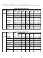
ÏAll values in foot pounds and (Newton meters)
NomiGrade Designation
nal bolt and Standard
size
1/4 - 28
Zinc or If instructions call for :
Cadmium
Loctite
Loctite
Loctite
Plated
222 or
242
271
262
Loctite
272
Loctite
277
Bare
SAE Grade 1
ASTM A307
2.8
(3.80)
3.4
(4.61)
3.8
(5.15)
4.1
(5.56)
5.3
(7.18)
4.9
(6.64)
3.8
(5.15)
SAE Grade 2
4.7
(6.37)
5.6
(7.60)
6.3
(8.54)
6.9
(9.36)
8.8
(11.93)
8.1
(10.98)
6.3
(8.54)
SAE Grade 4
5.5
(7.46)
6.6
(8.95)
7.3
(9.90)
8.1
(10.98)
10.3
(13.96)
9.5
(12.88)
7.3
(9.90)
SAE Grade 5
ASTM A449
7.3
(9.90)
8.7
(11.80)
9.7
(13.15)
10.7
(14.50)
13.6
(18.44)
12.6
(17.08)
9.7
(13.15)
SAE Grade 7
8.9
(12.07)
10.7
(14.50)
11.9
(16.13)
13.1
(17.76)
16.6
(22.51)
15.4
(20.88)
11.9
(16.13)
SAE Grade 8
ASTM A354 Grade
BD
10.2
(13.83)
12.2
(16.54)
13.6
(18.44)
15.0
(20.34)
19.0
(25.76)
17.7
(23.99)
13.6
(18.44)
ASTM A354 Grade
BC
—
—
—
—
—
—
—
ÏAll values in foot pounds and (Newton meters)
Nominal Grade Designation
bolt size and Standard
Zinc or If instructions call for :
Cadmium
Loctite
Loctite
Loctite
Plated
222
242
271
or262
Loctite
272
Loctite
277
Bare
5/16 - 18 SAE Grade 1
ASTM A307
5.1
(6.91)
6.2
(8.40)
6.8
(9.22)
7.5
(10.17)
9.6
(13.02)
8.9
(12.07)
6.8
(9.22)
SAE Grade 2
8.5
(11.52)
10.2
(13.83)
11.3
(15.32)
12.5
(16.95)
15.9
(21.56)
14.7
(19.93)
11.3
(15.32)
SAE Grade 4
10.0
(13.56)
12.0
(16.27)
13.3
(18.03)
14.6
(19.79)
18.6
(25.22)
17.3
(23.46)
13.3
(18.03)
SAE Grade 5
ASTM A449
13.0
(17.63)
15.6
(21.15)
17.4
(23.60)
19.1
(25.90)
24.3
(32.95)
22.6
(30.64)
17.4
(23.60)
SAE Grade 7
16.1
(21.83)
19.3
(26.17)
21.5
(29.15)
23.6
(31.99)
30.1
(40.81)
27.9
(37.83)
21.5
(29.15)
SAE Grade 8 ASTM
A354 Grade BD
18.5
(25.08)
22.1
(29.96)
24.6
(33.35)
27.1
(36.74)
34.5
(46.78)
32.0
(43.39)
24.6
(33.35)
ASTM A354 Grade
BC
16.1
(21.83)
19.3
(26.17)
21.5
(29.15)
23.6
(31.99)
30.1
(40.81)
27.9
(37.83)
21.5
(29.15)
35
FASTENER TORQUE REQUIREMENTS
MSSM0101CE/9906AV (5 of 19)
ÏAll values in foot pounds and (Newton meters)
Nominal Grade Designation Zinc
If instructions call for :
bolt size and Standard
orCadmium
Loctite Loctite Loctite
Plated
222 or
242
271
262
Loctite
272
Loctite
277
Bare
5/16 - 24 SAE Grade 1
ASTM A307
5.6
(7.59)
6.7
(9.08)
7.4
(10.03)
8.2
(11.12)
10.4
(14.10)
9.6
(13.01)
7.4
(10.03)
SAE Grade 2
9.4
(12.74)
11.3
(15.32)
12.5
(16.94)
13.8
(18.71)
17.5
(23.73)
16.3
(22.09)
12.5
(16.94)
SAE Grade 4
11.0
(14.91)
13.2
(17.90)
14.6
(19.79)
16.1
(21.83)
20.5
(27.79)
19.0
(25.76)
14.6
(19.79)
SAE Grade 5
ASTM A449
14.4
(19.52)
17.2
(23.32)
19.1
(25.90)
21.1
(28.60)
26.8
(36.35)
24.9
(33.76)
19.1
(25.90)
SAE Grade 7
17.9
(24.27)
21.4
(29.01)
23.8
(32.27)
26.2
(35.52)
33.4
(45.28)
31.0
(42.03)
23.8
(32.27)
SAE Grade 8
ASTM A354 Grade
BD
20.4
(27.66)
24.4
(33.08)
27.1
(36.74)
29.9
(40.54)
38.0
(51.52)
35.3
(47.86)
27.1
(36.74)
ASTM A354 Grade
BC
—
—
—
—
—
—
—
ÏAll values in foot pounds and (Newton meters)
Nominal Grade
bolt size Designation and
Standard
3/8 - 16
Zinc or
Cadmium
Plated
If instructions call for :
Loctite
222 or
262
Loctite
242
Loctite
271
Loctite
272
Loctite
277
Bare
SAE Grade 1
ASTM A307
9.0
(12.20)
10.8
(14.64)
12.0
(16.27)
13.1
(17.76)
16.7
(22.64)
15.5
(21.01)
12.0
(16.27)
SAE Grade 2
14.9
(20.20)
17.9
(24.27)
19.9
(26.98)
21.9
(29.69)
27.9
(37.83)
25.9
(35.11)
19.9
(26.98)
SAE Grade 4
17.8
(24.13)
21.3
(28.88)
23.7
(32.13)
26.0
(35.25)
33.1
(44.87)
30.8
(41.76)
23.7
(32.13)
SAE Grade 5
ASTM A449
23.2
(31.45)
27.8
(37.69)
30.9
(41.89)
34.0
(46.09)
43.3
(58.70)
40.2
(54.50)
30.9
(41.89)
SAE Grade 7
28.7
(38.91)
34.4
(46.64)
38.2
(51.79)
42.0
(56.94)
53.5
(72.54)
49.7
(67.39)
38.2
(51.79)
SAE Grade 8
ASTM A354
Grade BD
32.7
(44.33)
39.2
(53.15)
43.6
(59.11)
48.0
(65.08)
61.0
(82.70)
56.7
(76.87)
43.6
(59.11)
ASTM A354
Grade BC
28.7
(38.91)
34.4
(46.64)
38.2
(51.79)
42.0
(56.94)
53.5
(72.54)
49.7
(67.39)
38.2
(51.79)
36
MSSM0101CE/9906AV (6 of 19)
ÏAll values in foot pounds and (Newton meters)
Nominal Grade Designation
bolt size and Standard
3/8 - 24
Zinc or
If instructions call for :
Cadmium
Loctite
Loctite
Loctite
Plated
222 or
242
271
262
Loctite
272
Loctite
277
Bare
SAE Grade 1
ASTM A307
10.2
(13.83)
12.2
(16.54)
13.6
(18.44)
15.0
(20.33)
19.0
(25.76)
17.7
(24.00)
13.6
(18.44)
SAE Grade 2
16.9
(22.91)
20.3
(27.52)
22.5
(30.52)
24.8
(33.62)
31.5
(42.70)
29.3
(39.73)
22.5
(30.50)
SAE Grade 4
20.0
(27.11)
24.0
(32.54)
26.7
(36.20)
29.4
(39.86)
37.4
(50.70)
34.7
(47.04)
26.7
(36.20)
SAE Grade 5
ASTM A449
26.2
(35.52)
31.4
(42.57)
34.9
(47.32)
38.4
(52.06)
48.9
(66.30)
45.4
(61.55)
34.9
(47.32)
SAE Grade 7
32.3
(43.79)
38.8
(52.60)
43.1
(58.44)
47.4
(64.26)
60.4
(81.89)
56.1
(76.06)
43.1
(58.43)
SAE Grade 8
ASTM A354 Grade
BD
36.9
(50.02)
44.3
(60.06)
49.2
(66.70)
54.1
(73.35)
68.9
(93.41)
64.0
(86.77)
49.2
(66.70)
ASTM A354 Grade
BC
—
—
—
—
—
—
—
ÏAll values in foot pounds and (Newton meters)
Nominal Grade Designation Zinc or
If instructions call for :
bolt size and Standard
CadmiumLoctite
Loctite
Loctite
Plated
222 or
242
271
262
Loctite
272
Loctite
277
Bare
7/16 - 14 SAE Grade 1
ASTM A307
14.0
(18.98)
17.0
(23.04)
19.14
(25.95)
21.0
(28.47)
27.0
(36.60)
25.0
(33.89)
19.0
(25.76)
SAE Grade 2
24.0
(32.54)
28.8
(39.05)
32.0
(43.39)
35.2
(47.72)
44.8
(60.74)
41.6
(56.40)
32.0
(43.39)
SAE Grade 4
28.3
(38.37)
34.0
(46.10)
37.7
(51.11)
41.5
(56.27)
52.8
(71.59)
49.1
(66.57)
37.7
(51.11)
SAE Grade 5
ASTM A449
37.1
(50.30)
44.5
(60.33)
49.5
(67.11)
54.4
(73.76)
69.3
(93.96)
64.3
(87.18)
49.5
(67.11)
SAE Grade 7
45.9
(62.23)
55.1
(74.70)
61.3
(83.11)
67.4
(91.38)
85.8
(116.33)
79.6
(107.92)
61.3
(83.11)
SAE Grade 8
ASTM A354 Grade
BD
52.5
(71.18)
63.0
(85.41)
70.0
(94.90)
77.0
(104.40)
98.0
(132.87)
91.0
(123.38)
70.0
(94.90)
ASTM A354 Grade
BC
45.7
(61.96)
54.9
(74.43)
61.0
(82.70)
67.1
(90.97)
85.4
(115.79)
79.3
(107.52)
61.0
(82.70)
37
FASTENER TORQUE REQUIREMENTS
MSSM0101CE/9906AV (7 of 19)
ÏAll values in foot pounds and (Newton meters)
Nominal Grade
bolt size Designation and
Standard
Zinc or
Cadmium
Plated
If instructions call for :
Loctite
222 or
262
Loctite
242
Loctite
271
Loctite
272
Loctite
277
Bare
7/16 - 20 SAE Grade 1
ASTM A307
16.0
(21.70)
19.2
(26.03)
21.3
(28.88)
23.5
(31.86)
29.9
(40.54)
27.7
(37.56)
21.3
(28.88)
SAE Grade 2
26.9
(36.48)
32.2
(43.66)
35.8
(48.54)
39.4
(53.42)
50.1
(67.93)
46.6
(63.18)
35.8
(48.54)
SAE Grade 4
31.6
(42.84)
37.9
(51.39)
42.1
(57.08)
46.3
(62.77)
59.0
(79.99)
54.7
(74.16)
42.1
(57.08)
SAE Grade 5
ASTM A449
41.4
(56.13)
49.7
(67.38)
55.2
(74.84)
60.8
(82.43)
77.3
(104.80)
71.8
(97.35)
55.2
(74.84)
SAE Grade 7
51.3
(69.55)
61.5
(83.38)
68.4
(92.74)
75.2
(101.96)
95.7
(129.75)
88.9
(120.53)
68.4
(92.74)
SAE Grade 8
ASTM A354
Grade BD
58.2
(78.90)
69.9
(94.77)
77.7
(105.35)
85.4
(115.78)
108.7
(147.37)
101.0
(136.94)
77.7
(105.35)
ASTM A354
Grade BC
—
—
—
—
—
—
—
ÏAll values in foot pounds and (Newton meters)
Nominal Grade
bolt size Designation and
Standard
1/2 - 13
Zinc or
Cadmium
Plated
If instructions call for :
Loctite
222
or262
Loctite
242
Loctite
271
Loctite
272
Loctite
277
Bare
SAE Grade 1
ASTM A307
22.0
(29.83)
26.0
(35.25)
29.38
(39.83)
32.0
(43.39)
41.0
(55.59)
38.0
(51.52)
29.0
(39.32)
SAE Grade 2
36.6
(49.62)
43.9
(59.52)
48.8
(66.16)
53.6
(72.67)
68.3
(92.60)
63.4
(85.96)
48.8
(66.16)
SAE Grade 4
43.1
(58.44)
51.8
(70.23)
57.5
(77.96)
63.3
(85.82)
80.5
(109.14)
74.8
(101.42)
57.5
(77.96)
SAE Grade 5
ASTM A449
56.7
(76.87)
68.1
(92.33)
75.6
(102.5)
83.2
(112.80)
105.9
(143.58)
98.3
(133.27)
75.6
(102.50)
SAE Grade 7
69.8
(94.64)
83.8
(113.62)
93.1
(126.23)
102.4
(138.84)
130.4
(176.80)
121.1
(164.19)
93.1
(126.23)
SAE Grade 8
ASTM A354
Grade BD
79.7
(108.05)
95.6
(129.62)
106.3
(144.12)
116.9
(158.50)
148.8
(201.75)
138.1
(187.24)
106.3
(144.12)
ASTM A354
Grade BC
69.8
(94.64)
83.8
(113.62)
93.1
(126.23)
102.4
(138.84)
130.4
(176.80)
121.1
(164.19)
93.1
(126.23)
38
MSSM0101CE/9906AV (8 of 19)
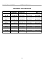
ÏAll values in foot pounds and (Newton meters)
Nominal Standard and
Zinc or
bolt size Grade Designation Cadmium
Plated
1/2 - 20
If instructions call for :
Loctite
222 or
262
Loctite
242
Loctite
271
Loctite
272
Loctite
277
Bare
SAE Grade 1
ASTM A307
24.8
(33.62)
29.8
(40.40)
33.1
(44.88)
36.4
(49.35)
46.4
(62.91)
43.1
(58.44)
33.1
(44.88)
SAE Grade 2
41.3
(56.00)
49.5
(67.11)
55.0
(74.57)
60.5
(82.02)
77.0
(104.40)
71.5
(96.94)
55.0
(74.57)
SAE Grade 4
48.8
(66.16)
58.5
(79.32)
65.0
(88.13)
71.5
(96.94)
91.0
(123.38)
84.5
(114.57)
65.0
(88.13)
SAE Grade 5
ASTM A449
63.8
(86.50)
76.5
(103.72)
85.0
(115.24)
93.5
(126.77)
119.0
(161.34)
110.5
(149.82)
85.0
(115.24)
SAE Grade 7
78.8
(106.84)
94.5
(128.12)
105.0
(142.36)
115.5
(156.60)
147.0
(199.30)
136.5
(185.07)
105.0
(142.36)
SAE Grade 8
ASTM A354 Grade
BD
90.0
(122.02)
108.0
(146.43)
120.0
(162.70)
132.0
(179.00)
168.0
(277.78)
156.0
(211.51)
120.0
(162.70)
ASTM A354 Grade
BC
—
—
—
—
—
—
—
ÏAll values in foot pounds and (Newton meters)
Nominal Grade Designation Zinc or
bolt size and Standard
Cadmium
Plated
If instructions call for :
Loctite
222
or 262
Loctite
242
Loctite
271
Loctite
272
Loctite
277
Bare
9/16 - 12 SAE Grade 1
ASTM A307
32.0
(43.39)
38.0
(51.52)
42.19
(57.20)
46.0
(62.37)
59.0
(80.00)
55.0
(74.57)
42
(56.94)
SAE Grade 2
52.7
(71.45)
63.3
(85.82)
70.3
(95.31)
77.3
(104.80)
98.4
(133.41)
91.4
(123.92)
70.3
(95.31)
SAE Grade 4
62.2
(84.33)
74.7
(101.28)
83.0
(112.53)
91.3
(123.79)
116.2
(157.55)
107.9
(146.30)
83.0
(112.53)
SAE Grade 5
ASTM A449
81.7
(110.77)
98.1
(133.00)
109.0
(147.78)
119.9
(162.56)
152.6
(206.90)
141.7
(192.17)
109.0
(147.78)
SAE Grade 7
100.7
(136.53)
120.9
(163.92)
134.3
(182.09)
147.7
(200.25)
188.0
(254.89)
174.6
(236.73)
134.3
(182.09)
SAE Grade 8
ASTM A354 Grade
BD
115.0
(155.92)
138.0
(187.10)
153.3
(207.85)
168.6
(228.59)
214.6
(290.96)
199.3
(270.21)
153.3
(207.85)
ASTM A354 Grade
BC
100.7
(136.53)
120.9
(163.92)
134.3
(182.09)
147.7
(200.25)
188.0
(254.89)
174.6
(236.73)
134.3
(182.09)
39
FASTENER TORQUE REQUIREMENTS
MSSM0101CE/9906AV (9 of 19)
ÏAll values in foot pounds and (Newton meters)
Nominal Grade Designation
bolt size and Standard
Zinc or If instructions call for:
Cadmium
Loctite
Loctite
Loctite
Plated
222 or
242
271
262
Loctite
272
Loctite
277
Bare
9/16 - 18 SAE Grade 1
ASTM A307
35.3
(47.86)
42.4
(57.49)
47.1
(63.86)
51.8
(70.23)
66.0
(89.48)
61.2
(82.98)
47.1
(63.86)
SAE Grade 2
59.1
(80.13)
70.9
(96.13)
78.8
(106.84)
86.6
(117.41)
110.3
(149.55)
102.4
(138.84)
78.8
(106.84)
SAE Grade 4
69.6
(94.36)
83.5
(113.21)
92.8
(125.82)
102.1
(138.43)
129.9
(176.12)
120.7
(163.65)
92.8
(125.85)
SAE Grade 5
ASTM A449
91.2
(123.65)
109.5
(148.46)
121.6
(164.87)
133.8
(181.40)
170.3
(230.90)
158.1
(214.36)
121.6
(164.87)
SAE Grade 7
112.3
(152.26)
134.8
(182.76)
149.8
(203.10)
164.7
(223.30)
209.7
(284.32)
194.7
(263.98)
149.8
(203.10)
SAE Grade 8
ASTM A354 Grade
BD
128.7
(174.61)
154.4
(209.34)
171.6
(232.66)
188.7
(255.84)
240.2
(325.67)
223.0
(302.35)
171.6
(232.66)
ASTM A354 Grade
BC
—
—
—
—
—
—
—
ÏAll values in foot pounds and (Newton meters)
Nominal Grade Designation
bolt size and Standard
5/8 - 11
Zinc or If instructions call for:
Cadmium
Loctite
Loctite
Loctite
Plated
222 or
242
271
262
Loctite
272
Loctite
277
Bare
SAE Grade 1
ASTM A307
44
(59.66)
52
(70.50)
58.2
(78.90)
64
(86.77)
81
(109.82)
76
(103.04)
58
(78.64)
SAE Grade 2
72.7
(98.57)
87.2
(118.23)
96.9
(131.38)
106.6
(144.53)
135.6
(183.85)
125.9
(170.70)
96.9
(131.38)
SAE Grade 4
86.1
(116.74)
103.4
(140.19)
114.8
(155.65)
126.3
(171.24)
160.8
(218.02)
149.3
(202.42)
114.8
(155.65)
SAE Grade 5
ASTM A449
112.5
(152.53)
135.0
(183.04)
150.0
(203.37)
165.0
(223.71)
210.0
(284.72)
195.0
(264.38)
150.0
(203.37)
SAE Grade 7
138.9
(188.32)
166.6
(225.88)
185.2
(251.10)
203.7
(276.18)
259.2
(351.43)
240.7
(326.35)
185.2
(251.10)
SAE Grade 8
ASTM A354 Grade
BD
158.8
(215.30)
190.5
(258.28)
211.7
(287.03)
232.9
(315.77)
296.4
(401.86)
275.2
(373.12)
211.7
(287.03)
ASTM A354 Grade
BC
139.2
(188.73)
167.0
(226.42)
185.5
(251.50)
204.1
(276.72)
259.8
(352.24)
241.2
(327.02)
185.5
(251.50)
40
MSSM0101CE/9906AV (10 of 19)
ÏAll values in foot pounds and (Newton meters)
Nominal Grade Designation
bolt size and Standard
5/8 - 18
Zinc or If instructions call for:
Cadmium
Loctite
Loctite
Loctite
Plated
222 or
242
271
262
Loctite
272
Loctite
277
Bare
SAE Grade 1
ASTM A307
49.5
(67.11)
59.4
(80.54)
66.0
(89.48)
72.6
(98.43)
92.4
(125.27)
85.8
(116.33)
66.0
(89.48)
SAE Grade 2
82.6
(112.00)
99.1
(134.36)
110.2
(149.41)
121.2
(164.33)
154.2
(209.07)
143.2
(194.15)
110.2
(149.41)
SAE Grade 4
97.3
(131.92)
116.7
(158.22)
129.7
(175.85)
142.7
(193.48)
181.6
(246.22)
168.6
(228.59)
129.7
(175.85)
SAE Grade 5
ASTM A449
127.7
(173.14)
153.3
(207.85)
170.3
(230.90)
187.3
(253.95)
238.4
(323.23)
221.4
(300.18)
170.3
(230.90)
SAE Grade 7
157.6
(213.68)
189.1
(256.39)
210.2
(285.00)
231.2
(313.47)
294.2
(398.88)
273.2
(370.41)
210.2
(285.00)
SAE Grade 8
ASTM A354 Grade
BD
179.9
(243.91)
215.9
(292.72)
239.8
(325.13)
263.8
(357.66)
335.8
(455.28)
311.8
(422.74)
239.8
(325.13)
ASTM A354 Grade
BC
—
—
—
—
—
—
—
ÏAll values in foot pounds and (Newton meters)
Nominal Grade Designation
bolt size and Standard
3/4 - 10
Zinc or If instructions call for:
Cadmium
Loctite
Loctite
Loctite
Plated
222 or
242
271
262
Loctite
272
Loctite
277
Bare
SAE Grade 1
ASTM A307
77
(104.40)
93
(126.09)
103.1
(139.78)
113
(153.20)
144
(195.24)
134
(181.68)
103
(139.65)
SAE Grade 2
129.4
(175.44)
155.3
(210.55)
172.5
(233.88)
189.8
(257.33)
241.5
(327.43)
224.3
(304.11)
172.5
(233.88)
SAE Grade 4
152.6
(206.90)
183.1
(248.25)
203.4
(275.77)
223.8
(303.43)
284.8
(386.14)
264.5
(358.61)
203.4
(275.77)
SAE Grade 5
ASTM A449
199.7
(270.76)
239.6
(324.85)
266.3
(361.05)
292.9
(397.12)
372.8
(505.45)
346.1
(469.25)
266.3
(361.05)
SAE Grade 7
246.8
(334.62)
296.2
(401.60)
329.1
(446.20)
362.0
(355.22)
460.7
(624.63)
427.8
(580.02)
329.1
(446.20)
SAE Grade 8
ASTM A354 Grade
BD
282.0
(382.34)
338.3
(458.67)
375.9
(509.65)
413.5
(560.63)
526.3
(713.57)
488.7
(662.59)
375.9
(509.65)
ASTM A354 Grade
BC
246.4
(334.07)
295.7
(400.92)
328.6
(445.53)
361.5
(490.13)
460.0
(623.67)
427.2
(579.20)
328.6
(445.53)
41
FASTENER TORQUE REQUIREMENTS
MSSM0101CE/9906AV (11 of 19)
ÏAll values in foot pounds and (Newton meters)
Nominal Grade Designation
bolt size and Standard
3/4 - 16
Zinc or If instructions call for:
Cadmium
Loctite
Loctite
Loctite
Plated
222 or
242
271
262
Loctite
272
Loctite
277
Bare
SAE Grade 1
ASTM A307
86.5
(117.28)
103.8
(140.73)
115.3
(156.33)
126.8
(171.92)
161.4
(218.83)
149.9
(203.24)
115.3
(156.33)
SAE Grade 2
144.1
(195.37)
173.0
(234.56)
192.2
(260.59)
211.4
(286.62)
269.1
(364.85)
249.8
(338.68)
192.2
(260.59)
SAE Grade 4
170.2
(230.76)
204.2
(276.86)
226.9
(307.64)
249.6
(338.41)
317.6
(430.61)
294.9
(399.15)
226.9
(307.64)
SAE Grade 5
ASTM A449
222.9
(302.21)
267.5
(362.68)
297.2
(402.95)
326.9
(443.22)
416.1
(564.16)
386.3
(523.75)
297.2
(402.95)
SAE Grade 7
275.6
(373.66)
330.8
(448.50)
367.5
(498.26)
404.3
(548.16)
514.5
(697.57)
477.8
(647.81)
367.5
(498.26)
SAE Grade 8
ASTM A354 Grade
BD
315.0
(427.08)
378.0
(512.50)
420.0
(569.44)
462.0
(626.39)
588.0
(797.22)
546.0
(740.28)
420.0
(569.44)
ASTM A354 Grade
BC
—
—
—
—
—
—
—
ÏAll values in foot pounds and (Newton meters)
Nominal Grade Designation
bolt size and Standard
7/8 - 9
Zinc or If instructions call for:
Cadmium
Loctite
Loctite
Loctite
Plated
222 or
242
271
262
Loctite
272
Loctite
277
Bare
SAE Grade 1
ASTM A307
124.7
(169.07)
149.6
(202.83)
166.3
(225.47)
182.9
(247.98)
232.8
(315.63)
216.1
(293.0)
166.3
(225.47)
SAE Grade 2
124.7
(169.07)
149.6
(202.83)
166.3
(225.47)
182.9
(247.98)
232.8
(315.63)
216.1
(293.00)
166.3
(255.47)
SAE Grade 4
246.1
(333.67)
295.3
(400.37)
328.1
(444.84)
360.9
(489.32)
459.4
(622.86)
426.6
(578.40)
328.1
(444.84)
SAE Grade 5
ASTM A449
322.4
(437.11)
386.9
(524.57)
429.8
(582.73)
472.8
(641.03)
601.8
(815.93)
558.8
(757.63)
429.8
(582.73)
SAE Grade 7
397.9
(539.48)
477.4
(647.27)
530.5
(719.26)
583.5
742.7
689.6
(791.12) (1007.00) (935.00)
530.5
(719.26)
SAE Grade 8
ASTM A354 Grade
BD
454.5
(616.22)
545.3
(739.33)
605.9
(821.49)
666.5
848.3
787.7
605.9
(903.65) (1150.14) (1067.98) (821.49)
ASTM A354 Grade
BC
397.9
(539.48)
477.4
(647.27)
530.5
(719.26)
583.5
742.7
689.6
(791.12) (1007.00) (935.00)
42
530.5
(719.26)
MSSM0101CE/9906AV (12 of 19)
ÏAll values in foot pounds and (Newton meters)
Nominal Grade Designation
bolt size and Standard
7/8 - 14
Zinc or If instructions call for:
Cadmium
Loctite
Loctite
Loctite
Plated
222 or
242
271
262
Loctite
272
Loctite
277
Bare
SAE Grade 1
ASTM A307
137.8
(186.83)
165.4
(224.25)
183.8
(249.20)
202.1
(274.01)
257.3
(348.85)
238.9
(323.90)
183.8
(249.20)
SAE Grade 2
137.8
(186.83)
165.4
(224.25)
183.8
(249.20)
202.1
(274.01)
257.3
(348.85)
238.9
(323.90)
183.8
(249.20)
SAE Grade 4
271.5
(368.11)
325.8
(441.73)
362.0
(490.80)
398.2
(539.89)
506.8
(687.13)
470.6
(638.05)
362.0
(490.80)
SAE Grade 5
ASTM A449
355.2
(481.59)
426.2
(577.85)
473.6
(642.12)
521.0
(706.38)
663.0
(898.91)
615.7
(834.78)
473.6
(642.12)
SAE Grade 7
438.0
(593.85)
525.7
(712.75)
584.1
(791.93)
642.5
817.7
759.3
584.1
(871.11) (1108.65) (1029.47) (791.93)
SAE Grade 8
ASTM A354 Grade
BD
501.2
(679.54)
601.5
(815.53)
668.3
(906.09)
735.1
935.6
868.8
668.3
(996.66) (1268.50) (1177.94) (906.09)
ASTM A354 Grade
BC
—
—
—
—
—
—
—
ÏAll values in foot pounds and (Newton meters)
Nominal Grade Designation
bolt size and Standard
1-8
Zinc or If instructions call for:
Cadmium
Loctite
Loctite
Loctite
Plated
222 or
242
271
262
Loctite
272
Loctite
277
Bare
SAE Grade 1
ASTM A307
187.5
(254.22)
225.0
(305.06)
250.0
(338.95)
275.0
(372.85)
350.0
(474.54)
325.0
(440.64)
250.0
(338.95)
SAE Grade 2
187.5
(254.22)
225.0
(305.06)
250.0
(338.95)
275.0
(372.85)
350.0
(474.54)
325.0
(440.64)
250.0
(338.95)
SAE Grade 4
369.4
(500.84)
443.3
(601.03)
492.5
(667.74)
541.8
(734.58)
689.5
(934.84)
640.3
(868.13)
492.5
(667.74)
SAE Grade 5
ASTM A449
482.8
(654.59)
579.4
(785.56)
643.8
(872.88)
708.1
901.3
836.9
643.8
(960.05) (1222.00) (1134.69) (872.88)
SAE Grade 7
596.3
(808.47)
715.5
795.0
874.5
1113.0
1033.5
795.0
(970.09) (1077.88) (1185.66) (1509.03) (1401.24) (1077.88)
SAE Grade 8
ASTM A354 Grade
BD
681.6
817.9
908.8
999.6
1272.3
1181.4
908.8
(924.13) (1108.92) (1232.17) (1355.28) (1725.00) (1601.77) (1232.17)
ASTM A354 Grade
BC
596.7
(809.01)
716.1
795.6
875.2
1113.9
1034.3
795.6
(970.90) (1078.69) (1186.61) (1510.25) (1402.32) (1078.69)
43
FASTENER TORQUE REQUIREMENTS
MSSM0101CE/9906AV (13 of 19)
ÏAll values in foot pounds and (Newton meters)
Nominal Grade
bolt size Designation and
Standard
1 - 12
Zinc or
Cadmium
Plated
If instructions call for :
Loctite
222 or
262
Loctite
242
Loctite
271
Loctite
272
Loctite
277
Bare
SAE Grade 1
ASTM A307
205.3
278.35
246.4
(334.07)
273.8
(371.22)
301.1
(408.24)
383.3
(519.69)
355.9
(482.54)
273.8
(371.22)
SAE Grade 2
205.3
(278.35)
246.4
(334.07)
273.8
(371.22)
301.1
(408.24)
383.3
(519.69)
355.9
(482.54)
273.8
(371.22)
SAE Grade 4
404.1
(547.88)
484.9
(657.44)
538.8
(730.52)
592.6
754.3
700.4
(803.46) (1022.70) (949.62)
538.8
(730.52)
SAE Grade 5
ASTM A449
528.8
(716.96)
634.5
(860.27)
705.0
775.5
987.0
916.5
705.0
(955.85) (1051.44) (1338.19) (1242.61) (955.85)
SAE Grade 7
652.5
(884.67)
783.0
870.0
957.0
1218.0
1131.0
870.0
(1061.60) (1179.56) (1297.52) (1651.39) (1533.42) (1179.56)
SAE Grade 8
ASTM A354
Grade BD
746.3
(1011.85)
895.5
995.0
1094.5
1393.0
1293.5
995.0
(1214.14) (1349.04) (1483.49) (1888.66) (1753.73) (1349.04)
ASTM A354
Grade BC
—
—
—
—
—
—
—
ÏAll values in foot pounds and (Newton meters)
Nominal Grade
bolt size Designation and
Standard
1 - 14
Zinc or
Cadmium
Plated
If instructions call for :
Loctite
222 or
262
Loctite
242
Loctite
271
Loctite
272
Loctite
277
Bare
SAE Grade 1
ASTM A307
210.0
(284.72)
252.0
(341.66)
280.0
(379.63)
308.0
(417.60)
392.0
(531.48)
364.0
(493.52)
280.0
(379.63)
SAE Grade 2
210.0
(284.72)
252.0
(341.66)
280.0
(379.63)
308.0
(417.60)
392.0
(531.48)
364.0
(493.52)
280.0
(379.63)
SAE Grade 4
413.4
(560.50)
496.1
(672.62)
551.3
(747.46)
606.4
771.8
716.6
(822.17) (1046.42) (971.58)
551.3
(747.46)
SAE Grade 5
ASTM A449
540.9
(733.36)
649.1
(880.06)
721.3
793.4
1009.8
937.6
721.3
(977.95) (1075.70) (1369.10) (1271.22) (977.95)
SAE Grade 7
668.4
(906.23)
802.1
891.3
980.4
1247.8
1158.6
891.3
(1087.50) (1208.44) (1329.25) (1691.79) (1570.85) (1208.44)
SAE Grade 8
ASTM A354
Grade BD
764.1
(1035.98)
916.9
1018.8
1120.6
1426.3
1324.4
1018.8
(1243.15) (1381.31) (1519.33) (1933.80) (1795.65) (1381.30)
ASTM A354
Grade BC
—
—
—
44
—
—
—
—
MSSM0101CE/9906AV (14 of 19)
ÏAll values in foot pounds and (Newton meters)
Nominal Grade Designation
bolt size and Standard
Zinc or If instructions call for :
Cadmium
Loctite
Loctite
Loctite
Plated
222 or
242
271
262
Loctite
272
Loctite
277
Bare
1-1/8 • 7 SAE Grade 1
ASTM A307
265.8
(360.37)
318.9
(432.37)
354.4
(480.50)
389.8
(528.50)
496.1
(672.62)
460.7
(624.63)
354.4
(480.50)
SAE Grade 2
265.8
(360.37)
318.9
(432.37)
354.4
(480.50)
389.8
(528.50)
496.1
(672.62)
460.7
(624.63)
354.4
(480.50)
SAE Grade 4
523.1
(709.23)
627.8
(851.18)
697.5
767.3
976.5
906.8
697.5
(945.68) (1040.32) (1323.96) (1229.46) (945.68)
SAE Grade 5
ASTM A449
595.9
(807.93)
715.1
794.5
874.0
1112.3
1032.9
794.5
(969.55) (1077.20) (1184.99) (1508.07) (1400.43) (1077.20)
SAE Grade 7
844.8
1013.8
1126.4
1239.0
1577.0
1464.3
1126.4
(1145.40) (1374.53) (1527.20) (1679.86) (2138.13) (1985.33) (1527.20)
SAE Grade 8
ASTM A354 Grade
BD
966.1
1159.3
1288.1
1416.9
1803.4
1674.6
1288.1
(1309.86) (1571.80) (1746.43) (1921.06) (2445.08) (2270.46) (1746.43)
ASTM A354 Grade
BC
844.8
1013.8
1126.4
1239.0
1577.0
1464.3
1126.4
(1145.40) (1374.53) (1527.20) (1679.86) (2138.13) (1985.33) (1527.20)
ÏAll values in foot pounds and (Newton meters)
Nominal Grade Designation
bolt size and Standard
Zinc or If instructions call for :
Cadmium
Loctite
Loctite
Loctite
Plated
222 or
242
271
262
Loctite
272
Loctite
277
Bare
1-1/8 • 12 SAE Grade 1
ASTM A307
297.4
(403.22)
356.9
(483.89)
396.6
(537.72)
436.2
(591.40)
555.2
(752.75)
515.5
(698.93)
396.6
(537.72)
SAE Grade 2
297.4
(403.22)
356.9
(483.89)
396.6
(537.72)
436.2
(591.40)
555.2
(752.75)
515.5
(698.93)
396.6
(537.72)
SAE Grade 4
586.4
(795.05)
703.7
781.9
860.1
1094.6
1016.4
781.9
(954.09) (1060.12) (1166.14) (1484.08) (1378.06) (1060.12)
SAE Grade 5
ASTM A449
667.6
801.1
890.2
979.2
1246.2
1157.2
890.2
(905.14) (1086.15) (1206.95) (1327.62) (1689.62) (1568.95) (1206.95)
SAE Grade 7
948.2
1137.8
1264.2
1390.6
1769.9
1643.5
1264.2
(1285.58) (1542.65) (1714.02) (1855.40) (2399.66) (2228.30) (1714.02)
SAE Grade 8
ASTM A354 Grade
BD
1083.2
1299.8
1444.2
1588.6
2021.9
1877.5
1444.2
(1468.62) (1762.30) (1958.07) (2153.85) (2741.33) (2545.55) (1958.07)
ASTM A354 Grade
BC
—
—
—
45
—
—
—
—
FASTENER TORQUE REQUIREMENTS
MSSM0101CE/9906AV (15 of 19)
ÏAll values in foot pounds and (Newton meters)
Nominal Grade
Zinc or
bolt size Designation and Cadmium
Standard
Plated
1-1/4 • 7
If instructions call for :
Loctite
222 or
262
Loctite
242
Loctite
271
Loctite
272
Loctite
277
Bare
SAE Grade 1
ASTM A307
375.0
(508.43)
450.0
(610.11)
500.0
(677.91)
550.0
(745.70)
700.0
(949.07)
650.0
(881.28)
500.0
(677.91)
SAE Grade 2
375.0
(508.43)
450.0
(610.11)
500.0
(677.91)
550.0
(745.70)
700.0
(949.07)
650.0
(881.28)
500.0
(677.91)
SAE Grade 4
738.3
(1001.00)
885.9
984.4
1082.8
1378.1
1279.7
984.4
(1201.12) (1334.67) (1468.08) (1868.45) (1735.04) (1334.67)
SAE Grade 5
ASTM A449
840.2
(1139.16)
1008.3
1120.3
1232.3
1568.4
1456.4
1120.3
(1367.07) (1518.93) (1670.78) (2126.47) (1974.62) (1518.93)
SAE Grade 7
1191.8
(1615.87)
1430.2
1589.1
1748.0
2224.7
2065.8
1589.1
(1939.09) (2154.53) (2369.97) (3016.30) (2800.85) (2154.53)
SAE Grade 8
ASTM A354
Grade BD
1362.9
(1847.85)
1635.5
1817.2
1998.9
2544.1
2362.3
1817.2
(2217.44) (2463.80) (2710.15) (3449.34) (3202.85) (2463.80)
ASTM A354
Grade BC
1192.4
(1616.68)
1430.9
1589.8
1748.8
2225.8
2066.8
1589.8
(1940.04) (2155.48) (2371.05) (3017.78) (2802.20) (2155.48)
ÏAll values in foot pounds and (Newton meters)
Nominal Grade
Zinc or
bolt size Designation and Cadmium
Standard
Plated
If instructions call for :
Loctite
222 or
262
Loctite
242
Loctite
271
Loctite
272
Loctite
277
Bare
1-1/4 • 12 SAE Grade 1
ASTM A307
414.8
(562.40)
497.8
(674.93)
553.1
(749.90)
608.4
774.4
719.1
(824.88) (1049.95) (974.97)
553.1
(749.90)
SAE Grade 2
414.8
(562.40)
497.8
(674.93)
553.1
(749.90)
608.4
774.4
719.1
(824.88) (1049.95) (974.97)
553.1
(749.90)
SAE Grade 4
816.8
(1107.43)
980.2
1089.1
1198.0
1524.7
1415.8
1089.1
(1328.97) (1476.62) (1624.27) (2067.22) (1919.57) (1476.62)
SAE Grade 5
ASTM A449
930.5
(1261.60)
1116.6
1240.6
1364.7
1736.9
1612.8
1240.6
(1513.90) (1682.03) (1850.29) (2354.92) (2186.66) (1682.03)
SAE Grade 7
1320.7
(1790.63)
1584.8
1760.9
1937.0
2465.3
2289.2
1760.9
(2148.70) (2387.46) (2626.22) (3342.50) (3103.74) (2387.46)
SAE Grade 8
ASTM A354
Grade BD
1509.4
(2046.47)
1811.3
2012.5
2213.8
2817.5
2616.3
2012.5
(2455.80) (2728.59) (3001.51) (3820.02) (3547.23) (2728.58)
ASTM A354
Grade BC
—
—
—
46
—
—
—
—
MSSM0101CE/9906AV (16 of 19)
ÏAll values in foot pounds and (Newton meters)
Nominal Grade Designation Zinc or
bolt size and Standard
Cadmium
Plated
If instructions call for :
Loctite
222 or
262
Loctite
242
Loctite
271
Loctite
272
Loctite
277
Bare
1-3/8 • 6 SAE Grade 1
ASTM A307
491.1
(665.84)
589.4
(799.12)
654.8
(887.79)
720.3
916.8
851.3
654.8
(976.60) (1243.00) (1154.21) (887.80)
SAE Grade 2
491.1
(665.84)
589.4
(799.12)
654.8
(887.79)
720.3
916.8
851.3
654.8
(976.60) (1243.00) (1154.21) (887.80)
SAE Grade 4
968.1
(1312.57)
1161.7
1290.8
1419.9
1807.1
1678.0
1290.8
(1575.06) (1750.10) (1925.13) (2450.10) (2275.07) (1750.09)
SAE Grade 5
ASTM A449
1102.1
(1494.25)
1322.6
1469.5
1616.5
2057.3
1910.4
1469.5
(1793.20) (1992.38) (2191.68) (2789.33) (2590.16) (1992.38)
SAE Grade 7
1563.6
(2119.96)
1876.4
2084.8
2293.3
2918.8
2710.3
2084.8
(2544.06) (2826.61) (3109.30) (3957.37) (3674.68) (2826.61)
SAE Grade 8
ASTM A354 Grade
BD
1786.6
(2422.30)
2144.0
2382.2
2620.4
3335.1
3096.8
2382.2
(2906.88) (3229.83) (3552.79) (4521.80) (4198.70) (3229.83)
ASTM A354 Grade
BC
1563.6
(2119.96)
1876.4
2084.8
2293.3
2918.8
2710.3
2084.8
(2544.06) (2826.61) (3109.30) (3957.37) (3674.68) (2826.61)
ÏAll values in foot pounds and (Newton meters)
Nominal Grade
bolt size Designation and
Standard
Zinc or
Cadmium
Plated
If instructions call for :
Loctite
222 or
262
Loctite
242
Loctite
271
Loctite
272
Loctite
277
Bare
1-3/8 • 12 SAE Grade 1
ASTM A307
559.5
(758.58)
671.3
745.9
820.5
1044.3
969.7
745.9
(910.16) (1011.30) (1112.45) (1415.88) (1314.74) (1011.30)
SAE Grade 2
559.5
(758.58)
671.3
745.9
820.5
1044.3
969.7
745.9
(910.16) (1011.30) (1112.45) (1415.88) (1314.74) (1011.30)
SAE Grade 4
1102.1
(1494.25)
1322.6
1469.5
1616.5
2057.3
1910.4
1469.5
(1793.21) (1992.38) (2191.68) (2789.33) (2590.16) (1992.38)
SAE Grade 5
ASTM A449
1254.3
(1700.60)
1505.1
1672.3
1839.6
2341.3
2174.0
1672.3
(2040.64) (2267.34) (2494.16) (3174.38) (2947.55) (2267.34)
SAE Grade 7
1780.2
(2413.63)
2136.2
2373.6
2611.0
3323.0
3085.7
2373.6
(2896.30) (3218.17) (3540.04) (4505.39) (4183.65) (3218.17)
SAE Grade 8
ASTM A354
Grade BD
2034.1
(2757.87)
2441.0
2712.2
2983.4
3797.1
3525.8
2712.2
(3309.56) (3677.25) (4044.95) (5148.18) (4780.35) (3677.25)
ASTM A354
Grade BC
—
—
—
47
—
—
—
—
FASTENER TORQUE REQUIREMENTS
MSSM0101CE/9906AV (17 of 19)
ÏAll values in foot pounds and (Newton meters)
Nominal Grade
bolt size Designation and
Standard
Zinc or
Cadmium
Plated
If instructions call for :
Loctite
222 or
262
Loctite
242
Loctite
271
Loctite
272
Loctite
277
Bare
1-1/2 • 6 SAE Grade 1
ASTM A307
652.5
(884.67)
783.0
870.0
957.0
1218.0
1131.0
870.0
(1061.60) (1179.56) (1297.52) (1651.39) (1533.43) (1179.56)
SAE Grade 2
652.5
(884.67)
783.0
870.0
957.0
1218.0
1131.0
870.0
(1061.60) (1179.56) (1297.52) (1651.39) (1533.43) (1179.56)
SAE Grade 4
1283.9
(1740.74)
1540.7
1711.9
1883.1
2396.6
2225.4
1711.9
(2088.91) (2321.03) (2553.14) (3249.36) (3017.24) (2321.03)
SAE Grade 5
ASTM A449
1462.5
(1982.88)
1755.0
1950.0
2145.0
2730.0
2535.0
1950.0
(2379.46) (2643.85) (2908.23) (3701.39) (3437.00) (2643.85)
SAE Grade 7
2074.2
(2812.24)
2489.1
2765.6
3042.2
3871.9
3595.3
2765.6
(3374.77) (3749.66) (4124.67) (5249.60) (4874.58) (3749.66)
SAE Grade 8
ASTM A354
Grade BD
2370.9
(3214.51)
2845.1
3161.3
3477.4
4425.8
4109.6
3161.3
(3857.44) (4286.15) (4714.73) (6000.58) (5571.88) (4286.15)
ASTM A354
Grade BC
2074.9
(2813.20)
2489.9
2766.6
3043.2
3873.2
3596.5
2766.6
(3375.85) (3751.01) (4126.03) (5251.36) (4876.20) (3751.01)
ÏAll values in foot pounds and (Newton meters)
Nominal Grade
bolt size Designation and
Standard
Zinc or
If instructions call for :
Cadmium
Loctite
Loctite
Loctite
Plated
222 or
242
271
262
Loctite
272
Loctite
277
Bare
1-1/2 • 12 SAE Grade 1
ASTM A307
734.1
(995.30)
880.9
978.8
1076.6
1370.3
1272.4
978.8
(1194.34) (1327.07) (1459.67) (1857.88) (1725.14) (1327.07)
SAE Grade 2
734.1
(995.30)
880.9
978.8
1076.6
1370.3
1272.4
978.8
(1194.34) (1327.07) (1459.67) (1857.88) (1725.14) (1327.07)
SAE Grade 4
1445.6
1734.8
1927.5
2120.3
2698.5
2505.8
1927.5
(1959.97) (2352.07) (2613.34) (2874.33) (3658.68) (3397.41) (2613.34)
SAE Grade 5
ASTM A449
1645.3
1974.4
2193.8
2413.1
3071.3
2851.9
2193.8
(2230.73) (2676.93) (2974.40) (3271.73) (4164.13) (3866.66) (2974.40)
SAE Grade 7
2334.4
2801.3
3112.5
3423.8
4357.5
4046.3
3112.5
(3165.02) (3798.06) (4219.99) (4642.05) (5907.98) (5486.05) (4219.99)
SAE Grade 8
ASTM A354
Grade BD
2667.7
3201.2
3556.9
3912.6
4979.6
4623.9
3556.9
(3616.92) (4340.25) (4822.51) (5304.78) (6751.44) (6269.17) (4822.51)
ASTM A354
Grade BC
—
—
—
48
—
—
—
—
MSSM0101CE/9906AV (18 of 19)
ÏOther Fastener Torque Specifications
ÏAll values in foot-pounds and (Newton-meters)
Nominal bolt size
18 - 8
Stainless Steel
316
Stainless Steel
Brass
Aluminum
2024 - T4
1/4 - 20
6.3 (8.54)
6.6 (8.95)
5.1 (6.91)
3.8 (5.15)
1/4 - 28
7.8 (10.57)
8.3 (11.25)
6.4 (8.67)
4.8 (6.50)
5/16 - 18
11.0 (14.90)
11.5 (15.60)
8.9 (12.06)
6.7 (9.08)
5/16 - 24
11.8 (16.00)
12.3 (16.67)
9.7 (13.15)
7.2 (9.76)
3/8 - 16
19.7 (26.71)
20.6 (27.93)
16.0 (21.70)
11.9 (16.13)
3/8 - 24
21.6 (29.28)
22.6 (30.64)
17.7 (24.00)
13.1 (17.76)
7/16 - 14
31.3 (42.44)
32.8 (44.47)
26.4 (35.80)
19.0 (25.76)
7/16 - 20
33.3 (45.15)
34.8 (47.18)
27.3 (37.00)
20.2 (27.38)
1/2 - 13
43.1 (58.43)
45.2 (61.28)
35.2 (47.72)
26.1 (35.38)
1/2 - 20
45.1 (61.14)
47.1 (63.86)
36.9 (50.00)
27.3 (37.00)
9/16 - 12
56.8 (77.00)
59.4 (80.53)
46.5 (63.04)
34.4 (46.64)
9/16 - 18
62.7 (85.00)
65.6 (88.94)
51.3 (69.55)
38.0 (51.52)
5/8 - 11
92.5 (125.41)
96.7 (131.10)
75.6 (102.50)
59.6 (80.80)
5/8 - 18
103.7 (140.60)
108.4 (146.97)
84.7 (114.84)
66.5 (90.16)
3/4 - 10
127.5 (172.86)
131.8 (178.70)
104.1 (141.14)
81.7 (110.77)
3/4 - 16
124.2 (168.39)
129.8 (175.98)
101.7 (137.88)
79.8 (108.19)
49
FASTENER TORQUE REQUIREMENTS
MSSM0101CE/9906AV (19 of 19)
ÏOther Fastener Torque Specifications
ÏAll values in foot-pounds and (Newton-meters)
Nominal bolt size
18 - 8
Stainless Steel
316
Stainless Steel
Brass
Aluminum
2024 - T4
7/8 - 9
194.0 (263.03)
202.5 (274.55)
158.8 (215.30)
124.6 (168.93)
7/8 - 14
193.2 (261.94)
201.7 (273.47)
157.9 (214.08)
124.2 (168.40)
1-8
286.7 (388.71)
299.6 (406.20)
234.6 (318.07)
183.8 (249.20)
1 - 14
259.2 (351.43)
270.8 (367.16)
212.1 (287.57)
166.3 (225.47)
1-1/8 • 7
413.0 (559.95)
432.0 (585.71)
337.0 (456.91)
265.0 (359.29)
1-1/8 • 12
390.0 (528.77)
408.0 (553.17)
318.0 (431.15)
251.0 (340.31)
1-1/4 • 7
523.0 (709.09)
546.0 (740.28)
428.0 (580.30)
336.0 (455.55)
1-1/4 • 12
480.0 (650.80)
504.0 (683.33)
394.0 (534.19)
308.0 (417.60)
1-1/2 • 6
888.0 (1203.97)
930.0 (1260.91)
727.0 (985.68)
570.0 (772.82)
1-1/2 • 12
703.0 (953.14)
732.0 (992.46)
575.0 (779.60)
450.0 (610.12)
50
Section
Drive Assemblies
51
2
52
R
4
2
1
5
P. O. Box 400, Kenner, LA 70063-0400
Pellerin Milnor Corporation
30015T5J,T5E & 30022T5J,T5E
Drive Chart
3,6
Parts List—Drive Chart
Item
Part Number
Description
Comments
D33 03260
94000Z DRIVE CHART-3015/22V4 60CYC
30015 & 30022T5J
1
2
3
4
5
6
all
all
all
all
all
all
15E230
56Q0RJA
560260R3JA
56Q1KSF
56VR082XB3
562240R3SF
STRMACHKEY 3/8SQX2+1/2 TOL.+0
7/8" BUSHING VPUL QD TYPE "JA"
VPUL 3G3V2.60 QD TYPE JA
1+1/2" BUSH VPUL QD TYPE SF
VBAND 3R3VX820 EA = 1 BELT
VPUL 3G3V22.4 (SF) MTO SPECIAL
-------------------------------------------------------------------COMPONENTS------------------------------------------------------------------
A
---------------------------------------------------------------------ASSEMBLIES------------------------------------------------------------------
. Used In
Find the correct assembly first, then find the needed components. The item letters (A, B, C, etc.) assigned to
assemblies are referred to in the "Used In" column to identify which components belong to an assembly. The item
numbers (1, 2, 3, etc.) assigned to components relate the parts list to the illustration.
Litho in U.S.A.
BMP000006/2001036V
(Sheet 1 of 1)
53
R
4
2
1
5
P. O. Box 400, Kenner, LA 70063-0400
Pellerin Milnor Corporation
30015V7J & 30022V6J
Drive Chart
3
Parts List— Drive Chart
D33 02860
B
93000Z DRIVE CHART=3022V7 VSP 60CYC
93000Z DRIVE CHART=3022V7 VSP 50CYC
30015V7J & 30022V6J
50 CYCLE
30015V7J & 30022V6J
60 CYCLE
2
3
4
5
all
all
all
all
56Q1CH
56030B2H
56Q1KSD
1+1/8" BUSH VPUL TYP H,D,OR QT
VPUL 2B3.0/A2.6 2BK32H R EQUAL
1+1/2" BUSH VPUL QD TYPE SD
56VB071XM2 VBELT BX71 MATCHSET2 EA=1BELT
2 BELT SET
-------------------------------------------------------------------COMPONENTS-----------------------------------------------------------------all
1
561825B2SD VPUL 2B18.25 (SD) MTO
D33 02850
A
Item Part Number
Description
Comments
. Used In
---------------------------------------------------------------------ASSEMBLIES------------------------------------------------------------------
Find the correct assembly first, then find the needed components. The item letters (A, B, C, etc.) assigned to
assemblies are referred to in the "Used In" column to identify which components belong to an assembly. The item
numbers (1, 2, 3, etc.) assigned to components relate the parts list to the illustration.
Litho in U.S.A.
BMP000007/2000455V
(Sheet 1 of 1)
54
R
7
7
4
5,6
(2 PLACES)
3
P. O. Box 400, Kenner, LA 70063-0400
Pellerin Milnor Corporation
2
30015, 30022, 36026, & 42026Vxx,Txx
Motor Mount
1
SEE
DETAIL A
30022V6J, T5J, T5E
MOUNTING
4
(1 SPRING ON
PULLEY END)
14,15
13
DETAIL A
(4 PLACES)
10
8
12
11
9
(ITEM 15, TUBE, SLIDES
OVER SHAFT TO
TIGHTEN BELT)
36026V5J, V7J, & 42026V6J
MOUNTING
13
4
(1 SPRING ON
PULLEY END)
Litho in U.S.A.
BMP000008/2001036V
(Sheet 1 of 2)
BMP000008/2001036V
(Sheet 2 of 2)
R
Pellerin Milnor Corporation
P. O. Box 400, Kenner, LA 70063-0400
Litho in U.S.A.
Parts List—Motor Mount
Find the correct assembly first, then find the needed components. The item letters (A, B, C, etc.) assigned to
assemblies are referred to in the "Used In" column to identify which components belong to an assembly. The item
numbers (1, 2, 3, etc.) assigned to components relate the parts list to the illustration.
Item
9. Used In
Part Number
Description
Comments
---------------------------------------------------------------------ASSEMBLIES-----------------------------------------------------------------A
ADB3022S4
ASSY=DRIVE BASE, 3022S4
30015V7J,T5J,T5E
30022V6J,T5J,T5E
36026V5J,V7J ,42026V6J
-------------------------------------------------------------------COMPONENTS-----------------------------------------------------------------all
1
02 04256
PLATE=MOTOR MNT, 3022S4
all
2
02 04257
BRKT=MOTOR MOUNT, 3022S4
all
3
02 04258
SHAFT=MOTOR MOUNT, 3022S4
all
4
02 04259
SPRNG/MOT MOUNT/3022S4#SPC2690
all
5
02 19283
NUT=1/2-13UNCX1+1/25Q SPEC
all
6
15K162
HXCAPSCR 1/2-13UNC2AX1.5 GR5 P
all
7
54JH10750C
SHFTCOLLAR 3/4" CLPTYP CFG#12S
all
8
15K095
HXCPSCR 3/8-16UNC2AX1 GR5 ZINC
all
9
15G205
HXNUT 3/8-16UNC2B ZINC GR2
all
10
15U255
LOCKWASHER MEDIUM 3/8 ZINCPL
all
11
15U240
FLATWASHER(USS STD) 3/8" ZNC P
all
12
15U241
FLATWASHER 13/32IDX1+3/4ODX14G
All
13
54JH10750C
SHFTCOLLAR 3/4” CLPTYP CFG#12
All
14
02 04258
2000142B SHAFT=MOTOR MOUNT, 3022S4
All
15
02 04258B
2000342B TUBE MOTOR MOUNT SPRING ADJ
55
56
Section
Bearing Assemblies
57
3
58
R
** 11
DETAIL C
PUSH-OFF
HOLES
CYLINDER
8
A
A
**
19
10
9
** 11
SEE DETAIL C
PULLER
MOUNTING
HOLES
*** 620PLACES
6
7
30015M4A SPIDER
SHOWN (00A)
SHELLFRONT
5
P. O. Box 400, Kenner, LA 70063-0400
Pellerin Milnor Corporation
30015, 30020, & 30022 Rigid Mount Washer Extractors
25
27
23
24
24
23
SHELL
26
25
25
24
28
Cylinder, Shell, Bearing, and Console Installation
23
12
*
13
21
TEMPORARY BEARING
INSTALLATION BOLTS
(6 PLACES)
14
*
**
***
**
21
21
**
16
THIS DRAWING REPRESENTS
ALL 30015 AND 30020
MACHINE MODELS, SEE
PARTS LIST FOR PARTS
WHICH APPLY TO YOUR
MACHINE.
30015M6 AND ALL
30020 MODELS
30020 MODELS ONLY
30015 MODELS ONLY
15
BEARING
HOUSING
42
29
** 18
*
37 38
*
39 40
17
DETAIL B-B
36
CONSOLE
30
41
***
REAR
REINFORCING
PLATE
36
9
8
DETAIL A-A
CYLINDER
SHELLFRONT
B
B
SHIM TO ENSURE AN
AIR GAP BETWEEN
THE CYLINDER
ALIGNING WASHER
AND REAR BEARING
SUPPORT.
32 31
33
34
35
REAR
BEARING HOUSING
MOUNTING BOLTS
Litho in U.S.A.
BMP910037/2001036V
(Sheet 1 of 2)
59
Parts List—Cylinder,Shell,Bearing,Console Installation
P. O. Box 400, Kenner, LA 70063-0400
Pellerin Milnor Corporation
Item
Part Number
Description
Comments
* CYL ASSY=3015C6M
ACA33C6M
ACA33C5M
ACA3020M7
ACA3022M5
ASH33023
ASH33008
ASH33015
ASH33007
ASH33030
ASH33031
ASH33024
ASH33010
ASH33009
ASH33019
ASH33032
ASH33033
ASH33034
ASH33035
ASH3022V5
ASH33040
B
C
D
E
F
G
H
I
J
K
L
M
N
O
P
Q
R
S
T
U
30015C4A,M4X,C4T,
K5X,S5X,30015T5J,T5E
30015V7J
30015M6X
30020M4A,C4A,M5X
30020M7X
30022M4X,M5X,K5X,C5X
30022V6J,30022T5J
30015M4A,M4T
30015C4A,C4T
30015M4G,M4J,M4P
30015M6A,M6G,M6J,
M6P,M6T
30015K5A,K5T
30015S5A,S5G,S5J,S5T
30020M4A
30020C4A
30020M5G,M5J,M5P
30020M7G,M7J,M7P
30022K5A,K5T
30022S5A,S5G,S5J,S5T
30022M4X,M5X
30022C5X
30022V5J,T5J
30015V7J,30015T5J
all
all
all
all
all
A
B
C
D
E
all
all
all
all
all
all
all
1
2
3
4
4
5
5
5
5
5
6
6
6
6
7
7
7
15B200
15U350
02 11196
02 14359
02 14359A
ACA02CWE
ACA33C6M
ACA33C5M
ACA3020M7
ACA3022M5
02 02138A
02 03703
02 03703A
02 03703J
X2 02758
X2 03561
X2 03561A
HEXCAPSCR 3/4-10X1+3/4 SS18-8
LOCKWASHER 3/4 MED SS18-8
COVER=SHAFT RETAINER=304S/S
SPACER SHT RETNR-LG OUR MATL
SHAFT RETNR SPACER 2+3/4" SQ
CYL ASSY=3015CWE/NMA/C4M/OE
* CYL ASSY=3015C6M
* CYL ASSY=3020C5M
CYL ASSY=3020 M7J/G/P
*CYL ASSY=3022 M5/C/K/S
CYLTIEROD-3/3015W+CWU 18-8SS
CYLINDER TIE ROD C5M SU$30
CYLINDER TIE ROD 3020M7
CYLINDER TIE ROD 3022S5
SPIDER=1/CWU+25W
SPIDER=C6M ONLY-CASTIRON
SPIDER C5M
PART OF 005A & 005B
PART OF 005C
PART OF 005D
PART OF 005E
PART OF 005A
PART OF 005B
PART OF 005C & 005E
-------------------------------------------------------------------COMPONENTS------------------------------------------------------------------
SHELL+CONSOLE 3015K4
SHELL+CONSOLE 3015S5
SHELL+CONSOLE 3020M4A
SHELL+CONSOLE 3020C4A-MICRO
SHELL+CONSOLE 3020M5-MICRO
SHELL+CONSOLE 3020M7-MICRO
SHELL+CONSOLE 3022K4
SHELL+CONSOLE 3022S5
SHELL+CONSOLE 3022M5
SHELL+CONSOLE 3022C4
ASSY=SHELL+CONSOLE, 3022V5
SHELL+CONSOLE 3015V7
SHELL+CONSOLE 3015M4A
SHELL+CONSOLE 3015C4-MICRO
SHELL+CONSOLE 3015M4
SHELL+CONSOLE 3015 M6-MICRO
* CYL ASSY=3020C5M
CYL ASSY=3020 M7J/G/P
*CYL ASSY=3022 M5/C/K/S
CYL ASSY=3015CWE/NMA/C4M/OE
ACA02CWE
A
---------------------------------------------------------------------ASSEMBLIES------------------------------------------------------------------
. Used In
Find the correct assembly first, then find the needed components. The item letters (A, B, C, etc.) assigned to
assemblies are referred to in the "Used In" column to identify which components belong to an assembly. The item
numbers (1, 2, 3, etc.) assigned to components relate the parts list to the illustration.
R
8
9
10
11
12
13
13
14
15
16
16
17
18
19
19
20
21
22
23
24
25
26
26
27
28
29
30
31
32
33
34
35
36
37
38
39
40
41
42
all
all
all
all
all
all
all
all
all
all
all
all
all
all
all
All
7
all
all
all
all
all
all
All
all
all
all
all
all
all
all
all
All
all
all
all
all
all
all
all
all
Used In
Item
15K086
15K086
17N071
15G218
15U245
15U312
02 03397
15U300
15K182
02 02181
15K046S
15G168
15N146
15G130
02 03559
W2 03770B
Y2 02059
02 02087C
02 03629
X2 03576
02 03444
02 03446
02 03575
02 03574
02 03568
02 03574
02 03335
02 03749
02 03560
15K126
15K196
20C013C
20C036A
15K182
02 02293
15U245
24G030N
15K096
15K100
X2 03561B
Part Number
HXCAPSCR 3/8-16NCX3/4 SS18-8
HXCAPSCR 3/8-16NCX3/4 SS18-8
NUT J-TYPE T#C33952-3816-3B 3/
HXLOKNUT NYL 3/8-16 STL/ZNC
FLTWASH 3/8 STD COMM 18-8 SS
FLAWASHER 3/4ODX33/64IDX11GA Z
CYLINDER ALIGNING WASHER
LOKWASHER REGULAR 1/2 ZINC PLT
HEXTAPSCR 1/2-13X2ZINC GR5 FUL
GUARD=SHELL MOUNT RING CLIP
HEXCAPSCR 1/4-20UNC2A X 2.25 S
SQNUT 1/4-20UNC2 SS18-8
RDMACHSCR 10-24UNC2X1 SS18-8
HEXMACHSCRNUT 10-24UNC2 SS18-8
SUPPORT=REAR BRG HOUSE
WLMT=REAR CONSOLE, 3022V5
*SHELL CLAMP RING=30" MACHINE
EXTRUS*ION-SHELL=30"MACHINES (
LOCKSTRAP=BEAR HOUS S/S
RING=SHELL BACK CLAMP=1/C6M
RING=SHELL BACK CLAMP
1 GASKET=SHELBACK CLAMPRING
GASKET=SHELLBAKCLAMPRING=CWM
GASKET=MAIN BEARINGHOUSE=CWM
PLATE-BG HOUSING REINFORCING
GASKET=MAIN BEARINGHOUSE=CWM
GASKET BEARING HOUSING CWE
BAR=REINF STRIP 3015
TAPSTRIP=BEARING SUPPORT
HEXCAPSCR 3/8-16NCX2+1/2SS18-8
HEXCAPSCR 1/2-13UNC2X3 18-8SS
GSKT ELIM.250CC LCT#504-41
PERMATEX NO 2C IN 11 OZ TUBES
HEXTAPSCR 1/2-13X2ZINC GR5 FUL
DOOR HANDLE NUT GASKET
FLTWASH 3/8 STD COMM 18-8 SS
ROLLED WASH.379ID NYLTITE 37W
HEXCAPSCR 3/8-16UNC2X1SS18-8
HEXCAPSCR 3/8-16X1+1/4 SS18-8
SPIDER=FABRICATED 3020M7
Description
30015MODELS ONLY
30015C4A,M4A
30015C4A,M4A
30015M6X,
30020+30022
30020+30022
30020+30022
30015
30015
30020+30022
30020+30022
30020+30022
30020+30022
30015
30015
30020+30022
30015
30020+30022
PART OF 005D
Comments
Litho in U.S.A.
BMP910037/2001036V
(Sheet 1 of 2)
60
R
A
A
B
B
FRONT
SHAFT
SEAL
HOLDER
SECTION B-B
P. O. Box 400, Kenner, LA 70063-0400
Pellerin Milnor Corporation
30015V7J, T5J, T5E, M6x
Main Bearing Assembly
1
2
VENT
9
SECTION A-A
12 13 14 15
DRAIN
26 25 24
12 13 14 15
21
19
18
17
16
28
23
27
10
30
LEAK-OFF
FOR SEALS
8
22
29
5
7
GREASE
INLET FOR
MAIN BEARING
31
3
4
6
VENT
SHIMS
20
REAR
SEAL
BEARING
HOLDER
Litho in U.S.A.
BMP910034/2001036V
(Sheet 1 of 2)
BMP910034/2001036V
(Sheet 2 of 2)
R
Pellerin Milnor Corporation
P. O. Box 400, Kenner, LA 70063-0400
Litho in U.S.A.
Parts List—Main Bearing Assembly
Find the correct assembly first, then find the needed components. The item letters (A, B, C, etc.) assigned to
assemblies are referred to in the "Used In" column to identify which components belong to an assembly. The item
numbers (1, 2, 3, etc.) assigned to components relate the parts list to the illustration.
Description
Item Part Number
Comments
. Used In
---------------------------------------------------------------------ASSEMBLIES-----------------------------------------------------------------A
SA 33 048
* BEARING ASSY 3015C6M ONLY
30015V6J, T5J,T5E, M6x
-------------------------------------------------------------------COMPONENTS-----------------------------------------------------------------all
all
all
all
all
all
all
all
all
1
2
3
4
5
6
7
8
9
02 02294A
15H089S
02 03311
24S005
24S005
60C151
60C150
24S015
54A319
SHAFT KEY 3/8 X 3/8
SPRINGPIN 1/8"DIA X 5/8" LONG
SEAL SLEEVE OUR MATL
SEAL 2.25 X 3.0 X .375 SS BUNA
SEAL 2.25 X 3.0 X .375 SS BUNA
ORING 3+7/8ID1/8CS BUNA70#241
ORING 3+3/4ID1/8CS BUNA70 #240
SEAL 2.265X3.256X.433 CR#23678
CUP 28920 TIMKN 2-24 1/BX+PT#
all
all
all
all
all
all
all
all
all
all
all
all
10
12
13
14
15
16
17
18
19
20
21
22
54A320
5SL0EBEC
03 01142
27A043A
60E005P
02 03407
15K127
X2 03659A
24S048AAA
X2 03314A
54A308
54A307
CONE 28985 TIMKN 2-51 1/BX+PT#
NPTELB 90DEG STRT 1/4 BRASS125
NIPPLE 1/4X1+1/4 BRASS
HOSECLAMP.562"DIA.SPRG#HC9STZD
PVC TUBING 1/2"ID X 5/8"OD
LOCKING WASHER ZINC PLATE
HEXFLGSCR 3/8-16X2 GR8 CS
HOUSE=SEAL+BRG 30M,V7
SEAL 1.625X2.375X.375 CS/BUNA
MAIN SHAFT=3015N6E+C6M
CONE M802048 TIM 2-24 1/BX+PT#
CUP M802011 TIMK 2-24 1/BX+PT#
all
all
all
all
23
23
23
23
02 03320B
02 03320C
02 03320D
02 03320G
SHIM .003 ARTUS GREEN
SHIM .005 ARTUS BLUE
SHIM .010 ARTUS BROWN
SHIM .0075 ARTUS TRANSMATTE
all
all
all
all
all
all
24
25
26
27
28
29
5SP0EFFSSM
5N0E01KBE2
5SCC0EBE
X2 03573
5N0E05AG42
02 03564
NPT PLUG 1/4 SQSLDMAGNET BLKST
NPT NIP 1/4X1.5TBE BRASS STD.
NPT COUP 1/4 BRASS 125# W/HEX
BEARHOUSE=C6M ONLY
NPT NIP 1/4X5 TBE GALSTL SK40
BOLT LOCKING TAB 1/4 BOLT
all
All
30
31
15B080
X2 03437
HEXCAPSCR 5/16 X1+1/4 SS-18-8
HOLDER=SHAFT SEAL=1/CWU
61
62
R
A
A
B
B
FRONT
SHAFT
SEAL
HOLDER
SECTION B-B
P. O. Box 400, Kenner, LA 70063-0400
Pellerin Milnor Corporation
30020 & 30022
Main Bearing Assembly
1
2
VENT
9
SECTION A-A
12 13 14 15
DRAIN
26 25 24
12 13 14 15
21
19
18
17
16
28
23
27
10
30
LEAK-OFF
FOR SEALS
8
22
29
5
7
GREASE
INLET FOR
MAIN BEARING
31
3
4
6
VENT
SHIMS
20
REAR
SEAL
BEARING
HOLDER
Litho in U.S.A.
BMP910033/2002446V
(Sheet 1 of 2)
63
Parts List—Main Bearing
P. O. Box 400, Kenner, LA 70063-0400
Pellerin Milnor Corporation
Item
Part Number
Description
Comments
ABM33001
A33 09901V
B
CC
MAIN BEARASY 3020C4/M5-VITON
BEARING ASSY=3020M7
* BEARING ASSY=C5M + N4M
30020M4A,C4A,C4E
M5X+30022M4X,M5X,
C5X,S5X,K5X
OPTIONAL VITON
30020M7X
30020M4A,C4A,C4E
M5X+30022M4X,M5X,
C5X,S5X,K5X
1
2
3
4
4
5
5
6
7
8
9
10
12
13
14
15
16
17
18
19
20
21
22
all
all
all
AB
C
AB
C
all
all
all
all
all
all
all
all
all
all
all
all
all
all
all
all
54A307
54A308
X2 13103A
24S048AAA
X2 03659A
15K127
02 03407
60E005P
27A043A
03 01142
5SL0EBEC
54A915
54A916
24S052A
60C151
60C151
24S053
24S053V
24S053
24S053V
02 13143
02 02294A
15H089S
CUP M802011 TIMK 2-24 1/BX+PT#
CONE M802048 TIM 2-24 1/BX+PT#
SHAFT,MAIN FOR 3020C5M+N4M
SEAL 1.625X2.375X.375 CS/BUNA
HOUSE=SEAL+BRG 30M,V7
HEXFLGSCR 3/8-16X2 GR8 CS
LOCKING WASHER ZINC PLATE
PVC TUBING 1/2"ID X 5/8"OD
HOSECLAMP.562"DIA.SPRG#HC9STZD
NIPPLE 1/4X1+1/4 BRASS
NPTELB 90DEG STRT 1/4 BRASS125
CONE TIMKN#JLM710949C 1/BX
CUP TIMKN#JLM710910 1/BX+PT#
SEAL 2.559X3.55X.315 CR#25430
ORING 3+7/8ID1/8CS BUNA70#241
ORING 3+7/8ID1/8CS BUNA70#241
SEAL 2.625X3.625X.437#10050LUP
SEAL 2.625X3.625X.437#10050LUP
SEAL 2.625X3.625X.437#10050LUP
SEAL 2.625X3.625X.437#10050LUP
SEALSLEEVE=SWE-1/SWE
SHAFT KEY 3/8 X 3/8
SPRINGPIN 1/8"DIA X 5/8" LONG
-------------------------------------------------------------------COMPONENTS------------------------------------------------------------------
A33 09901
A
---------------------------------------------------------------------ASSEMBLIES------------------------------------------------------------------
. Used In
Find the correct assembly first, then find the needed components. The item letters (A, B, C, etc.) assigned to
assemblies are referred to in the "Used In" column to identify which components belong to an assembly. The item
numbers (1, 2, 3, etc.) assigned to components relate the parts list to the illustration.
R
31
29
all
all
28
all
30
27
27
AC
B
all
26
all
25
24
all
all
23
23
23
23
23
23
all
all
all
all
All
all
Used In
Item
SHIM=.003 CRS GREEN
SHIM=.005 CRS BLUE
SHIM=.010 CRS RED
SHIM=.0075 CRS BLACK
SHIM=,020 CRS WHITE
SHIM=.050 CRS CLEAR
Description
Parts List, cont.—Main Bearing
HOUSING BEARING C5M
HOUSING=MAIN BEARING 3020M7
NPT COUP 1/4 BRASS 125# W/HEX
X2 13144A
15B080
02 03564
HOLDER=SHFT SEAL(05=24S052A)
HEXCAPSCR 5/16 X1+1/4 SS-18-8
BOLT LOCKING TAB 1/4 BOLT
5N0E05AG42 NPT NIP 1/4X5 TBE GALSTL SK40
X2 03573A
X2 13105A
5SCC0EBE
5N0E01KBE2 NPT NIP 1/4X1.5TBE BRASS STD.
5SP0EFFSSM NPT PLUG 1/4 SQSLDMAGNET BLKST
02 03323
02 03323A
02 03323B
02 03323C
02 03323D
02 03323E
Part Number
AS REQUIRED
AS REQUIRED
AS REQUIRED
AS REQUIRED
Comments
Litho in U.S.A.
BMP910033/2002446V
(Sheet 2 of 2)
64
Section
Shell and Door Assemblies
65
4
66
2
1
R
A
A
P. O. Box 400, Kenner, LA 70063-0400
Pellerin Milnor Corporation
3010 / 3015 G5E,G5X,CGE
30015 V7J,T5J,C4A,C4E & 30022 V6J,T5J,C4A,C4E
B
Shellfront Assembly, Conduit, & Interlock
B
7
6
8
9
FOR DOOR
ASSEMBLY, SEE
BMP920009.
5
4
12
11
FOR INTERLOCK
ASSEMBLY, SEE
BMP750046.
DOOR
HINGE
13
VIEW "A-A"
10
VIEW "B-B"
2.
1.
14
15 16 17 18
. DJUST THE LATCH SO THAT THE
A
MINIMUM ENGAGEMENT WITH THE DOOR
FULLY CLOSED EQUALS 1/4" +- 1/16"
(6.4mm +- 1.5mm).
ADJUST DOOR STRIKER SO THAT IT
TOUCHES THE LATCH SQUARELY AND
EVENLY.
ADJUSTMENTS:
MINIMUM LATCH
ENGAGEMENT
1/4" +- 1/16"
(6.4mm +-1.5mm)
LATCH
DOOR STRIKER
3
Litho in U.S.A.
BMP920024/2004055V
(Sheet 1 of 2)
67
Parts List—Shellfront, Conduit & Interlock
P. O. Box 400, Kenner, LA 70063-0400
Pellerin Milnor Corporation
Item
Part Number
Description
Comments
A33 10100H
A33 10100M
A33 10100N
A33 10100F
A33 10100G
B
C
D
E
F
SHLFRTASY N/O ILOK W/PROX
*SHLASSY (IDNT) UNLOK C4A
SHLASSY N/LOCK 3015/22V/T
SHLASSY N/LOCK 3015/22S#G/J
SHELL FRONT ASSY 3015/20M4A
*SHLASSY (IDNT) UNLOK N4P
3010CGE,3015CGE,30015C4E
30022C4E
3015C4A, 3022C4A
3010G5E,G5X
3015G5E,G5X,V7J,T5E,T5J,T5X
3022V6J,T5E,T5J,T5X
3022S4J,S4G,S5J
3015K4A,S4J,S5G,S5J
3015M4A,C4T,M4T,M6A,M6T
3022M5T,3022C4T
3015M4G/J/P, M6J,D4A
3022M5G/J
8
9
10
11
12
13
14
14
15
16
17
all
all
all
all
all
all
ABCDE
F
all
all
all
5
all
6
4
all
7
3
3
3
3
A,B
C
D
F
all
2
2
2
A.C,D
B
EF
All
1
1
ABCDE
F
24G020N
15U180
15N174
15K084
02 03669
02 03669C
02 02293
02 02819C
15G200C
12P1ASSB
12K040
10Y71M4GEX
03 01446
12K040
01 10422
EDL00171
EDL00371
EDL00271
EDL00171C
A33 07100C
A33 07100H
A33 07100F
X2 02361B
X2 02361C
ROLLED WASH.252ID NYLTITE 25W
LOCKWASHER MEDIUM 1/4 ZINCPL
HXCAPSCR 1/4-20UNC2X5/8SS18-8
TRUSS HXSOK 3/8-16 X 23/32SS
GASKET=INTRLK HOUSING
GASKET=INTRLK HOUSING 8" LONG
DOOR HANDLE NUT GASKET
SPACER-SHELLFRONT/HINGE
HXCPNUT HI 3/8-16 BRASS NIK PL
SNAPBUSH 7/8"MH X 11/16
1/2"COND.EMT COND. PECO #260B
*M4G EXTERNAL CONNECTIONS
1/2 EMT CONDUIT 900D=DR INTR
1/2"COND.EMT COND. PECO #260B
NPLATE:DOOR ILOC->N4,5,6 P
INTRLKHSG ASSY=N/UNLOCK 240V
INTERLKHSG=N/LOCK+SWITCH240V
INTRLKHSG ASSY=N/LOCK 220V
INTRLKHSG ASSY=N/O W/ PROX 240
*DRASSY(INDNT)LK,LOGO N4,5,6P
95027 DOOR ASY 3015/3020M4A
95027# DRASSY (INDNT)LK,LOGO C4A
SHELLFRONT,30",ELECTRIC LOCK
2002296D SHELLFRT=30" ILOC W/PROX
-------------------------------------------------------------------COMPONENTS------------------------------------------------------------------
A33 10100C
A
.--------------------------------------------------------------------ASSEMBLIES------------------------------------------------------------------
. Used In
.
Find the correct assembly first, then find the needed components. The item letters (A, B, C, etc.) assigned to
assemblies are referred to in the "Used In" column to identify which components belong to an assembly. The item
numbers (1, 2, 3, etc.) assigned to components relate the parts list to the illustration.
R
All
Used In
18
Item
15G168
SQNUT 1/4-20UNC2 SS18-8
Description
Parts List, cont.—Shellfront, Conduit & Interlock
Part Number
Comments
Litho in U.S.A.
BMP920024/2004055V
(Sheet 2 of 2)
68
8
23
12
2
24
3
11
10
16
17
18
19
9
7
HINGE DETAIL
6
P. O. Box 400, Kenner, LA 70063-0400
Pellerin Milnor Corporation
VIEW A-A
R
30015 & 30022 Rigid Mount
Door Assembly
24
21,20
1
A
A
B
37
16,17,18,19
16,18,35,36
B
16,18,22,35
37
16
VIEW B-B
35
36
18
25
13
Litho in U.S.A.
BMP920009/2001036V
(Sheet 1 of 2)
BMP920009/2001036V
(Sheet 2 of 2)
R
Pellerin Milnor Corporation
P. O. Box 400, Kenner, LA 70063-0400
Litho in U.S.A.
Parts List—Door Assembly
Find the correct assembly first, then find the needed components. The item letters (A, B, C, etc.) assigned to
assemblies are referred to in the "Used In" column to identify which components belong to an assembly. The item
numbers (1, 2, 3, etc.) assigned to components relate the parts list to the illustration.
Item
. Used In
Part Number
Description
Comments
---------------------------------------------------------------------ASSEMBLIES-----------------------------------------------------------------A
A33 07100C
*DRASSY(INDNT)LK,LOGO N4,5,6P
30015V7J,T5J,T5E
3022V6J,T5J,T5E
3015V7G/V7J;3022V7G/V7J
3015M4G/J/P,M6J,D4A
3022M5G/J
3022S4J,S4G,S5J
3015K4A,S4J,S5G,S5J
B
A33 07100H
DOOR ASY 3015/3020M4A
30015M4A+30020M4A
ONLY
C
A33 06900F
ASSY=DOOR W/MLOGO DKRED 3022
3022F8J/F8P/F8W
-------------------------------------------------------------------COMPONENTS-----------------------------------------------------------------all
all
all
all
1
2
3
6
X2 02814C
02 02819
12P1AGHP1
02 02817
DOOR=SHELL W/1LOK-3020
HINGE=STAMPED DOOR 25#
HOLEPLUG 3/8"BLACK LPE
FLANGE BRG=DOOR HINGE-NYLON
A
B
C
7
7
7
02 09215D
02 09215A
02 09215E
DR GLASS=N4,5,6P W/MIL LOGO
DORGLAS=DRAW W/MILNOR LOGO
DOOR GLASS W/MIL LOGO (RED)
all
all
all
all
all
all
all
all
all
all
8
9
10
11
12
13
16
17
18
19
02 09021
02 02366
02 10545
02 10342A
02 02764
03 01420C
15G140
15K031
15U181
24G020N
RING=DOOR GLASS PRESSURE
GASKET DOORGLAS GTR52-5220-3
EXTR BAND-STAMPED SS CYLDOOR
GASKET=15" DOOR
HINGEPIN=SHELLDOOR L=10+5/8"
DOOR STRIKER=ILOC
HXCPNT 1/4-20 #C250=20 NKLPLT
BUTSOKCAPSCR 1/4-20X1/2 SS18-8
LOCKWASHER MEDIUM 1/4 SS18-8
ROLLED WASH.252ID NYLTITE 25W
all
all
all
all
all
all
all
all
all
20
21
22
23
24
25
35
36
37
60C080
15P103
15N173A
20C044
15Q077
03 01423C
15U188
15N191
03 01420D
RECESS BUMPER RUBBERLAVELLE #7
TRDCUT-F RDHDSLOT 8-32UNCX1/2
FLTMACSCR 1/4-20 UNCX5/8 UCUTS
ADHESIVE 3M EC-1300 IN PINT CO
SOKSETSCR 1/4-20X1/4 ZINC ALLE
LATCH GUARD ILOC 3015-20
FLTWASH 1/4 STD COMM SS18-8
FLATMACHSCR 1/4-20X7/8 SS18-8
DOOR HANDLE=ILOC 3015-20
69
70
SWITCH STRIKER ADJUSTMENT
SEE
BOLT
SPACER
ADJUSTMENT
Adjust the switch striker arm by bending as
shown so that :
1) The switch is activated when the door is
closed
2) The switch does not actuate when the
unlatching lever is fully depressed with the
door open
3) The arm does not over travel and hit the
switch housing when the door is closed
and the switch is actuated.
P. O. Box 400, Kenner, LA 70063-0400
Pellerin Milnor Corporation
SEE
SWITCH
STRIKER
ADJUSTMENT
R
Interlock Assembly
BOLT SPACER ADJUSTMENT
SIDE VIEW
Bolt Spacer Adjustment
1) On a new machine the slots on the front
housing should not show a gap past the
bolt spacers.
2) The spacers should be installed with the
long side toward the shellfront
ASSEMBLIES 00AA,00BB,00CC,00DD
FRONT VIEW
110V-120V=GREEN
220V-240V=YELLOW
Litho in U.S.A.
BMP750046/2001036V
(Sheet 1 of 2)
71
Parts List—Interlock Assembly
P. O. Box 400, Kenner, LA 70063-0400
Pellerin Milnor Corporation
Item
Part Number
Description
Comments
93207#*RR PIVOT PL ASSY=N/LOCK 220V
88093#*INTRLKHSG ASSY=N/LOCK 120V
93207# RR PIVOT PL ASSY=N/LOCK 120V
94000Z INTERLKHSG=N/LOCK+SWITCH240V
EDL00221
EDL00271A
EDL00337
EDL00337A
EDL00371
EDL00271A
EDL00271
B
BB
C
CC
D
DD
E
30022T5E
USED ON 00D & 00E
(CONTAINS ITEMS 15-28)
3022V6J,T5J
3022S4J,S4G,S5J
3015K4A,S4J,S5G,S5J
USED ON 00C
(CONTAINS ITEMS 15-28)
36&42QXX,BWP 3015D4A
36021V6J, 36026V5J
36026V7J, 42026V6J
USED ON 00B
(CONTAINS ITEMS 15-28)
3022F8J/P/W
3630F8J/P/W/S
USED ON 00A
(CONTAINS ITEMS 15-28)
30015V7J,T5J,T5E
3015/20/22 Mxx,Cxx,Vxx
1
2
2
3
3
4
5
6
7
8
9
10
all
all
D only
all
D only
all
all
all
all
all
all
all
03 01418
03 01418B
03 01417
03 01423
03 01425A
03 01335
03 01429
03 01427A
03 01427B
03 01426
03 01426A
09R014A
75100B TAP STRIP=ILOC
75194B KEEPER=LATCH PIN/NOTCH
75100B PLATE=SPACER=ILOC
75736B LATCH = INTERLOCK
92683C DOOR HANDLE EXTENSION
INSULATOR=AUTOSPOT
75479C PLATE=FNT PIVOT=ILOC
77181C HOUSING=REAR=ILOC (C-7)
94186D HOUSING=REAR=ILOC W/UNLATCH
77201D HOUSING=FRONT=ILOC
94186D HOUSING=FRONT= ILOC W/UNLATC
05ZMIMI-SW SPDT STAKON #V15G1C26K
-------------------------------------------------------------------COMPONENTS------------------------------------------------------------------
88093#INTRLKHSG ASSY=N/LOCK 220V
93207#*RR PIVOT PL ASSY=N/LOCK 220V
96411 INTRLKHSG ASSY=N/LOCK 220V
93207@ RR PIVOT PL ASSY=N/UNLOK240V
EDL00171A
AA
88093# INTRLKHSG ASSY=N/UNLOCK 240V
EDL00171
A
---------------------------------------------------------------------ASSEMBLIES------------------------------------------------------------------
. Used In
Find the correct assembly first, then find the needed components. The item letters (A, B, C, etc.) assigned to
assemblies are referred to in the "Used In" column to identify which components belong to an assembly. The item
numbers (1, 2, 3, etc.) assigned to components relate the parts list to the illustration.
R
15
15
16
17
17
17
AA,BB,DD
CC
all
AA
BB,DD
CC
25
26
27
27
28
AA only
all
B
BB,CC,DD
23
all
all
22
all
24
21
all
all
20
all
19
14
all
all
13
all
18
12
all
all
11
Used In
all
Item
03 01418C
27B205080Z
27B205080E
03 S1X1
15H090I
03 01443
03 01445B
03 01445
03 01444
03 01444A
03 01422
03 01425
03 01421B
03 01421A
03 01421D
03 01428A
09K062B71
09K062B37
15H091
03 01443
03 01442
75736B KEEPER=NORMLOCKED SLIDE=ILOC
SPCRROLL.177ID.218L.027T STLZC
01ZSPCRROLL.177ID.25L.027TK CSZNC
88172B SHIM:DOOR INTLK SOLENOID N4P
STRAIGHT PIN 5/32"DIAX1.75"LG ZINC
84251AFLATHDRIVET 5/32X2+5/16 ZINC
75935B TORQUE SPRING (.53 IN-#)CDPL
88481ASPRING .2/.625/.319+CADPL
82293ASPRING .51/1.69/46+CADPL
77503B SPRING CUP = ILOC
94256C KEEPER=SPRING=ILOC
75479B HANDLE=ILOC
93207B SLIDE=NORMALLY OPEN(C7 SOL)
75736B SLIDE=NORMALLY LOCKED=ILOC
77341B SLIDE=NORMALLY LOCKED(C7-S)
93207C PLATE=REAR PIVOT=ILOC (C-7)
04Z SOLENOID 240/60--220/50 = ILOC
03Z SOLENOID(C-7)120/60--110/50
01Z STRGHTPIN 5/32''X2.25 LG ZINC
84251AFLATHDRIVET 5/32X2+5/16 ZINC
92697B SOLENOID INSULATION=DR INTRK
Parts List, cont.—Interlock Assembly
Description
Part Number
03 01424A
90501B STRIKER=SWITCH=LONG TAB
(NOT SHOWN)
Comments
Litho in U.S.A.
BMP750046/2001036V
(Sheet 2 of 2)
72
Section
Chemical Supply Devices
73
5
74
R
SHELL
ITEMS 10,11&12
FASTEN SPLASH
GUARD ASSEMBLY TO
PLASTIC HOUSING
(4 PLACES).
10 11 12
00A
9
1
6
P. O. Box 400, Kenner, LA 70063-0400
Pellerin Milnor Corporation
14
5
15
1
1
2
GASKET
4
13 14
7
3 HOUSING
3010 & 3015 G5E,G5X 3010 & 3015CGE
30015V7J,T5J,T5E,C4A,C4T,C4E 30022V6J,T5J,T5E,C4A,C4T,C4E
Soap Chute Installation
Parts List—Soap Chute Installation
Item
Part Number
Description
Comments
2
3
4
5
6
7
9
10
11
12
13
14
15
all
all
all
all
all
All
all
all
all
all
all
all
1
all
all
15P051
24G018N
15P050
15G130
15U160
15N133
02 03593
02 03630A
02 03595
02 03594
02 03589T
02 03589I
02 03304D
02 03130
TRDFRM AB HOLTHD 10-16X3/4SS41
ROLLED WASH.194ID NYLTITE 10W
PHDCUT-F PANHD 10-32X3/4 SS410
HEXMACHSCRNUT 10-24UNC2 SS18-8
LOCKWASHER MEDIUM #10 SS18-8
RDMACSCR 10-24UNCZA X5/8" SS18
89432B LID-SOAPCHUTE CWE TY304 SS
SPLASH GUARD= SOAP CHUTE
PIN SOAP CHUTE HINGE=CWU
GUARD SOAP CHUTE=CWU
BACKING RING=PLSTC CHEM INLT
PLASTIC SHELLSIDE SOAP INLET
GASKET=SOAPCHUTE 1/8"EPDM BL
BRACKET=PLASTIC SOAP INLET
A
SA-33-058M 94000Z ASSY=PLSTC SOAP INLET
-------------------------------------------------------------------COMPONENTS------------------------------------------------------------------
---------------------------------------------------------------------ASSEMBLIES------------------------------------------------------------------
. Used In
Find the correct assembly first, then find the needed components. The item letters (A, B, C, etc.) assigned to
assemblies are referred to in the "Used In" column to identify which components belong to an assembly. The item
numbers (1, 2, 3, etc.) assigned to components relate the parts list to the illustration.
Litho in U.S.A.
BMP000040/2004055V
(Sheet 1 of 1)
75
R
6
P. O. Box 400, Kenner, LA 70063-0400
2
3
1
4
5
30022V6J,T5J,T5E,T5X,C4A,C4T
Pellerin Milnor Corporation
3010 & 3015 G5E,G5X,CGE
30015V7J,T5J,T5E,T5X,C4A,C4T
Peristaltic Supply Box
8,9
NOT USED
C4A,C4T
CGE
Parts List—Peristaltic Supply Box
Item
Part Number
Description
Comments
SA 33 058P
ASSY=PLSTC PERSTL REAR INLET
02 03588F
02 03588E
51PB0GN
20C040
7
8
9
15U181
5
6
15K031
51E513NU
3
4
51E513EBN
51E513N
2
1
SIL SEAL RTV BLACK 85GR #59330
PLUG PIPE 3/8"NPT P-38 HD POLY
PERISTALTIC/WATER INLET 30
3015/20 PERST BOX TOP BRKT
LOCKWASHER MEDIUM 1/4 SS18-8
BUTSOKCAPSCR 1/4-20X1/2 SS18-8
NUT 11/16 THRD.#64138 US PLAST
3/4" 90DEG. ELBOW W/NUT
HOSEADPT3/4"HX11/16 W/NUT=NYL.
-------------------------------------------------------------------COMPONENTS------------------------------------------------------------------
A
---------------------------------------------------------------------ASSEMBLIES------------------------------------------------------------------
. Used In
Find the correct assembly first, then find the needed components. The item letters (A, B, C, etc.) assigned to
assemblies are referred to in the "Used In" column to identify which components belong to an assembly. The item
numbers (1, 2, 3, etc.) assigned to components relate the parts list to the illustration.
Litho in U.S.A.
BMP000046/2004055V
(Sheet 1 of 1)
76
R
P. O. Box 400, Kenner, LA 70063-0400
Pellerin Milnor Corporation
3 Compartment Supply Injector
Litho in U.S.A.
BMP770149/2000333V
(Sheet 1 of 2)
BMP770149/2000333V
(Sheet 2 of 2)
R
Pellerin Milnor Corporation
Litho in U.S.A.
P. O. Box 400, Kenner, LA 70063-0400
Parts List—3 Compartment Supply Injector
Find the correct assembly first, then find the needed components. The item letters (A, B, C, etc.) assigned to
assemblies are referred to in the "Used In" column to identify which components belong to an assembly. The item
numbers (1, 2, 3, etc.) assigned to components relate the parts list to the illustration.
Item
. Used In
Part Number
Description
Comments
---------------------------------------------------------------------ASSEMBLIES-----------------------------------------------------------------A
GWS33001B
89241@ INSTALL 4SUP INJ SYSTEM 7
B
AWS33001B
89241D*ASSY=3FLUSH SUP INJ SYSTEM 7
3 COMPARTMENT SUPPLY
INSTALLATION
CONTAINS ITEMS 4-13
-------------------------------------------------------------------COMPONENTS-----------------------------------------------------------------all
1
02 03732B
94031B COVER 4 COMP SUPPLY VALVES
all
2
02 03732F
90346C TAPPED PLATE=SUPPLY MOUNT
all
3
02 03304A
94493C GASKET=SOAP CHUTE 1/8"EPDM
all
4
W2 03732
93102D* SUPPLY INJECTOR 4 COMP SUPP
all
5
02 03732G
87501C LID=4 COMPARTMENT SUPPLY
all
6
02 03732U
78302B GASKET=LID 4 COMP SUPPLY
all
7
02 03732S
78132B HINGE PIN=LID 4 COMP SUPPLY
all
8
02 03732T
77411B TUBE COPPER-VALVE CONN. 3/8
all
9
02 03732Z
83446B ADAPTER HOSETHD 3/4"X1/4 NPT
all
10
W2 03732A
93303B* SUPPLY CUP WLMT 4 COMP SUPP
all
11
96P013B71
04Z 3/4" 2WAY PLASTIC VALVE 240V60C
all
12
60C007
RUBGROM #2861 1/2ID-13/16X1/8PNL MT
all
13
53A060H
KNURLED HOSENUT 3/4-HOSE PH#94GH-12
all
14
01 10438X
95072B NPLT:3POCK SUPPLY SYSTEM7ISO
SYS 7 - HOTEL
all
14
01 10438Y
95072B NPLT:3POCK SUPPLY EP-PLUSISO
EP PLUS
all
14
01 10438L
92343C NPLT:M4A 3 COMPARTMENT SUPPY
M4A
77
78
Section
Water and Steam Piping
and Assemblies
79
6
80
P
R
GAS
STOP
VALVE
ON/OFF
MODULATING
VALVE
PRESSURE
SWITCH
2-WAY
VALVE
MALE
CONNECTOR
REDUCER
PIPE
PLUG
GAS
COCK
REGULATOR
ISOMETRIC SYMBOLS
P. O. Box 400, Kenner, LA 70063-0400
Pellerin Milnor Corporation
Schematic Symbols Key
M
STEAM VALVE
MOTOR
OPERATED
VALVE
ELECTRICALLY
OPERATED
2-WAY VALVE
ELECTRIC
VALVE
POSITIONER
PNEUMATIC
ACTUATOR
BALLVALVE
(THERMAL)
MANUAL
BALLVALVE
INLINE VALVE
NON-SPECIFIC
IN
EXHAUST
DEVICE
EXHAUST
DEVICE
IN
CYLINDER
AIR RETRACT
SPRING EXTEND
CYLINDER
AIR EXTEND
SPRING RETRACT
CYLINDER W/QUICK
EXHAUST VALVE
CYLINDER
(SINGLE ACTING)
CYLINDER
(DOUBLE ACTING)
3-WAY N/O
AIR PILOT
VALVE
3-WAY N/C
AIR PILOT
VALVE
STANDARD SYMBOLS
FLOW
SENSOR
GAUGE
RELIEF
VALVE
PRESSURE
REGULATOR
PRESSURE
SWITCH
CHECK
VALVE
STEAMTRAP
VACUUM
BREAKER
Y-STRAINER
SPECIAL PURPOSE
FILTER/STRAINER
AIR LINE
FILTER-AUTO
COIL
Litho in U.S.A.
BMP920008/2000302V
(Sheet 1 of 1)
81
R
SEWER
10
SEE
BMP920017
M
DRAIN
LEVEL 1
SHELL
1
LEVEL 2
PRESSURE
(LEVEL)
SWITCHES
P. O. Box 400, Kenner, LA 70063-0400
Pellerin Milnor Corporation
30015V7J,T5J,T5E 30022V6J, T5J,T5E
**
2
PERISTALTIC
SUPPLY
SEE BMP000046.
FLUSHING
WATER
3
*
4
FLUSHING WATER
- STRAINER MUST BE CLEANED, SEE "PREVENTIVE MAINTENANCE" IN THE TABLE OF CONTENTS.
2
HOT
WATER
3 COMPARTMENT
SUPPLY
- PRESSURE REGULATOR MUST REMAIN SET AT THE FACTORY SETTING OF 28 P.S.I. SEE BMP900031 FOR MAINTENANCE PROCEDURES.
*
HOT
WATER
ELECTRIC WATER
VALVES
COLD
WATER
OVERFLOW
STANDARD
Water / Steam / Drain Schematics
5
*
8
7
SEE
BMP920029
6
SEE
BMP890005
COOLDOWN
OPTIONS
ADD
STEAM
9
SEE
BMP920028
5
*
Litho in U.S.A.
BMP000049/2002044V
(Sheet 1 of 2)
BMP000049/2002044V
(Sheet 2 of 2)
R
Pellerin Milnor Corporation
P. O. Box 400, Kenner, LA 70063-0400
Litho in U.S.A.
Parts List—Water/Steam/Drain Schematic
Find the correct assembly first, then find the needed components. The item letters (A, B, C, etc.) assigned to
assemblies are referred to in the "Used In" column to identify which components belong to an assembly. The item
numbers (1, 2, 3, etc.) assigned to components relate the parts list to the illustration.
Item
Used In
Part Number
Description
Comments
---------------------------------------------------------------------ASSEMBLIES-----------------------------------------------------------------A
B
C
D
SA 33 058R
SA 33 058P
AWS33001B
SA 33 054A
3015/22 WATER VALVE ASSY
ASSY=PLSTC PERSTL REAR INLET
*ASSY=3FLUSH SUP INJ SYSTEM 7
*INLET ASSY=CLDN M4567J/P CWM
-------------------------------------------------------------------COMPONENTS-----------------------------------------------------------------all
1
09N086A
PRESS SWITCH EATON #738-761
all
2
96P053C71
3/4"INLET/OUTLET VALVE 220V
all
3
96P053D71
3/4"INLET 1/2"DUO OUTLET 220V
all
4
96P013B71
3/4" 2WAYPLASTICVAL 240V60C
all
5
51T025
Y-STRAINER 1/2" CAST IRON
all
6
96D034
BALLVALVE 1/2" WATTS #6400-SS
all
7
96TDC2AA71 1/2" N/C 2WAY 240V50/60C VALVE
all
8
96M021
1/2"VAC BREAKER #288A
all
9
96P039A37
1/2"STEAMVAL120V50/60C 150PSI
all
10
96P039A71
1/2"STEAMVAL240V50/60C 150PSI
all
11
96D350A71
DRINVAL 3"N/O MTRDR240V 50/60C
All
12
96J061
FLOW REGULATOR #MR04-101
82
83
3
15
16
17
18
19
4
R
5
2
4
8,9
P. O. Box 400, Kenner, LA 70063-0400
6
Pellerin Milnor Corporation
10
11
7
11
14
PERISTALTIC
SUPPLY
1
(SEE
BMP000046)
10
30015V7J, T5J, T5E, T5X, C4A 30022V6J, T5J, T5E, T5X, C4A, C4T
Water Inlet Assemblies with Peristaltic Supply
12
13
20
(6 PLACES)
Litho in U.S.A.
BMP000047/2003215V
(Sheet 1 of 2)
84
R
31
26
31
21
25
24
30
29
P. O. Box 400, Kenner, LA 70063-0400
Pellerin Milnor Corporation
22
27
27
23
28
28
6,7
30015V7J, T5J, T5E, T5X, C4A 30022V6J, T5J, T5E, T5X, C4A, C4T
Water Inlet Assemblies with Peristaltic Supply
8,9
8,9
Parts List—Water Inlet Assemblies
GA 33 058P
SA 33 058T
SA 33 058P
INST=H2O+PERSTAL REAR INLET
3015/22 BRASS WATER VALVE ASSY
ASSY=PLSTC PERSTL REAR INLET
SA 33 058P
02 03588B
12P11CSB
12P11KSB
12P11JSB
60E006C
27A044
60E008A
27A044S
60E010
27A090S
51AB1EN1A
60E014A02A
27A052
60C121
15G205
15U240
15U255
15K085
15P011
W2 03588S
96P058A71
51E502B
27A0650CLP
5N0E03KBE2
51E513A
96P057A71
51E510
27A0050
5N0K03KB42
51E513B
1
2
3
4
5
6
7
8
9
10
11
12
13
14
15
16
17
18
19
20
21
22
23
24
25
26
27
28
29
30
31
NPT NIP 1/2X3.5 TBE BRASS STD
3/4"MHX1/2"FP PARKER#80GH-12-8
NPT NIP 1/4X3.5 TBE BRASS STD
3/4"MHX1/4"FP PARKER#78GH-12-4
1/2"NPT X 1/2"ORIFICE 240V 5/6
HOSESTEM BRASS 1/2MPX3/4HOSEID
CLP-RGDSTL COND #PS1100-1/2
TRDCUT-F PANHD 10-24X1/2 NIKST
3015/22 BRASS H20 MNT WLMT
1/4"NPT X 1/8"ORIFICE 240V 5/6
HOSESTEM BRASS 1/4MPX1/8HOSEID
TUBING CLP 1/2"OD #PS1200-1/2
GROMMET-FILLTUBE3015/22
HXNUT 3/8-16UNC2B ZINC GR2
FLATWASHER(USS STD) 3/8" ZNC P
LOCKWASHER MEDIUM 3/8 ZINCPL
HEXCAPSCR 3/8-16UNC2AX3/4 GR5
TUBINGPOLYBRAID 1"X1.312
HOSECLAMP 13/16-1.5"SS#64016B
INSERT REDUCER PVC 1+1/4"X 1"
HOSE 1.25IDX2"LG PVC
HOSECLAMP 1.5"DIA.SPRING#R24HC
SNAPBUSH 1.50"MH X 1.312
PVC TUBING NYL.REINF.5IDX.75OD
HOSECLAMP 5/8"ID BREEZE#6706SS
TUBINGNYLREINF.75"IDX1.025"OD
HOSECLAMP 11/16-1.25SSCR#64012
ASSY=PLSTC PERSTL REAR INLET
PARISTALTIC/WATER INLET HOSE
SNAPBUSH 1.093"MH X .94"ID
SNAPBUSH 1.50" X 1.312
-------------------------------------------------------------------COMPONENTS------------------------------------------------------------------
A
B
C
Item Part Number
Description
Comments
Used In
---------------------------------------------------------------------ASSEMBLIES------------------------------------------------------------------
Find the correct assembly first, then find the needed components. The item letters (A, B, C, etc.) assigned to
assemblies are referred to in the "Used In" column to identify which components belong to an assembly. The item
numbers (1, 2, 3, etc.) assigned to components relate the parts list to the illustration.
Litho in U.S.A.
BMP000047/2003215V
(Sheet 2 of 2)
85
R
2
5
2
P. O. Box 400, Kenner, LA 70063-0400
Pellerin Milnor Corporation
30015V7J,T5J,T5E 30022V6J,T5J,T5E
Level Switches
1,8
3
4
6
LEVEL
SWITCHES
ITEMS 1-6
(T5E ONLY)
TO TRANSDUCER
7 ON PROCESSOR
BOARD, ALL VxJ
AND TxJ MACHINES
Parts List - Level Switches
Item
Part Number
Description
Comments
3
4
5
6
7
8
all
all
all
all
all
2
all
all
1
all
51E502P
60E002S
A33 12000J
27A052
02 03332C
60E005P
27A044A
51E509
HOSE ADPT.1/4"MPX3/16H POLY-E
PVC TUBING .170IDX.4370D CLR
PRES TUBE "T" ASSY MXJ
HOSECLAMP 1.5"DIA.SPRING#R24HC
AIRCHAMBER=PRESSWITH-CWU
PVC TUBING 1/2"ID X 5/8"OD
HOSECLAMP.687"ID ROTOR#HC11STR
HOSESTEM BRASS 1/2MPX1/2HOSEID
-------------------------------------------------------------------COMPONENTS------------------------------------------------------------------
. Used In
Find the correct assembly first, then find the needed components. The item letters (A, B, C, etc.) assigned to
assemblies are referred to in the "Used In" column to identify which components belong to an assembly. The item
numbers (1, 2, 3, etc.) assigned to components relate the parts list to the illustration.
Litho in U.S.A.
BMP000069/2001363V
(Sheet 1 of 1)
86
R
5
COUPLING NUT
4
3
BONNET
6
IF THE VALVE LEAKS BETWEEN THE BODY AND BONNET, LOOSEN THE
COUPLING NUT AND TURN THE BONNET SLIGHTLY, THEN TIGHTEN THE
COUPLING NUT. IF THE VALVE STILL LEAKS, REPEAT THE OPERATION. IN
NO CASE MUST THE COUPLING NUT BE TIGHTENED EXCESSIVELY.
1
7
8
2.
2
13
COUPLING NUTS MUST NOT BE TIGHTENED EXCESSIVELY. USE A STEADY
PULL WITH A 14" OR SMALLER WRENCH. DO NOT HAMMER ON NUT OR
WRENCH. LIMIT MAXIMUM TORQUE ON COUPLING NUT TO 600LB/INCH.
EXCESSIVE TIGHTENING OF COUPLING NUT WILL DISTORT VALVE BODY
CAUSING THE PISTON BODY TO JAM AND THE VALVE TO SHUT OFF.
12
1.
GENERAL MAINTENANCE:
9
14
15
P. O. Box 400, Kenner, LA 70063-0400
Pellerin Milnor Corporation
1/2” & 3/4” Hayes Electric Steam Valves
Parts List—Electric Steam Valve
Item
Part Number
Description
Comments
96P039A37
96P039A71
96P040E
96P040A37
B
C
D
E
3/4"STEAMVAL120V50/60C 150PSI
3/4"STEAMVAL 24V50/60C 150PSI
1/2"STEAMVAL240V50/60C 150PSI
1/2"STEAMVAL120V50/60C 150PSI
1/2"STEAMVAL 24V50/60C 150PSI
3/4" VALVE- 120 VOLT
3/4" VALVE- 24 VOLT
1/2" VALVE- 240 VOLT
1/2" VALVE- 120 VOLT
1/2" VALVE- 24 VOLT
5
5
6
6
7
8
8
8
9
9
12
13
A,B,C
D,E
A,B,C
D,E
all
A,D
B,E
C
A,B,C
D,E
all
all
15
4
4
A,B,C
D,E
all
3
3
A,B,C
D,E
14
2
2
A,B,C
D,E
all
1
1
A,B,C
D,E
96V262
96V264
96V251
96V250
96V222TS
96V222TSA
96P040V24
96P040V37
96P040V71
96V223
96V242
96V260
96V244
96V222A
96V246
96V254
96V248
96V226
96V225S
96V225SA
96V224S
96V224SA
FERRULE (COIL SLEEVE) HAYS #82
BOTTOM PLATE (COIL) HAYS#8223
SPRING WASHER HAYS #83600
PALNUT HAYS #3069-PC
TEFLONSPLIT RING HAYS #86334
TEFLON SPLITRING STEMVAL HAYS#
COIL 1/2"&3/4" STEAMVALVE 24V5
COIL 1/2"&3/4"STEAMVALVE 120V5
COIL 1/2"&3/4" STEAMVALVE 240V
PLUNGER HAYS #7319503
BONNET FOR HAYS 3108 HAYS83021
BONNET HAYS #83192 FOR 96P151
PISTON SPRING FOR HAYS 3/08
PISTON SPRING HAYS 82488
COUPLING NUT FOR 96P014&96P016
COUPLING NUT HAYS #76028 = 9
SEATWASHER NUT HAYS#82222 96P0
SEAT WASHER FOR 96P053 HAYS
PISTON SEAT WASHER HAYS #85553
PISTON SEAT WASHER HAYS #85567
PISTON ASSY STEAMVAL HAYS #763
PISTON ASSY STEAMVAL HAYS #777
-------------------------------------------------------------------COMPONENTS------------------------------------------------------------------
96P039
A
---------------------------------------------------------------------ASSEMBLIES------------------------------------------------------------------
. Used In
Find the correct assembly first, then find the needed components. The item letters (A, B, C, etc.) assigned to
assemblies are referred to in the "Used In" column to identify which components belong to an assembly. The item
numbers (1, 2, 3, etc.) assigned to components relate the parts list to the illustration.
Litho in U.S.A.
BMP920028/2000302V
(Sheet 1 of 1)
87
R
P. O. Box 400, Kenner, LA 70063-0400
Pellerin Milnor Corporation
2-Way Electric Water Valve
5
00A
00B
00C
CAUTION
Release pressure to valve before disassembly.
Maintenance
Allow solenoids to cool before servicing the valves.
READ ALL SAFETY STATEMENTS ABOVE BEFORE PROCEEDING ANY FURTHER!
+
BURN HAZARD Solenoid enclosures become too hot to touch when energized
for a long period. This will not damage the solenoid, but may cause a painful
burn.
+
Troubleshooting
Remove retaining clip.
Slip entire solenoid enclosure off the solenoid base sub-assembly.
Remove solenoid base sub-assembly, core assembly and core spring.
Remove diaphragm spring, diaphragm assembly and gasket.
Replace all worn or damaged parts.
Reassemble in reverse order.
Control Circuit: Listen for a metallic click when energizing the solenoid. Absence of the click
indicates loss of power to the solenoid. Check for loose connections, blown
fuses, open or grounded coil circuit, and broken lead wires.
Faulty coil: Check for open circuit in coil. Replace coil if necessary.
Low voltage: Voltage across coil leads must be at least 85% of nameplate rating for proper
operation.
Incorrect pressure: Pressure to valve must be within range specified on nameplate.
Excess leakage: Disassemble valve and clean all parts. Replace all worn parts for best
results.
1.
2.
3.
4.
5.
6.
Valve Disassembly and Reassembly
Remove retaining clip. NOTE: Whe metal retaining clip disengages, it springs upwards.
Slip yoke containg coil and sleeves off solenoid base sub-assembly.
Replace coil.
Reassemble in reverse order.
Coil Replacement
1.
2.
3.
4.
WARNING
Lock OFF and tag out power at wall disconnect before servicing. Power
switches on machine and control box disable only control circuit power in
electrical boxes.
EXPLOSION HAZARD may cause serious injury.
+
SHOCK HAZARD will cause death or severe injury.
DANGER
Safety Instructions
Check nameplate for correct catalog number, pressure, voltage, and service.
Identification and Description
Litho in U.S.A.
BMP920029/98443V
(Sheet 1 of 2)
BMP920029/98443V
(Sheet 1 of 2)
R
Pellerin Milnor Corporation
P. O. Box 400, Kenner, LA 70063-0400
Used In
Parts List—2-Way Electric Water Valve
Item
Part Number
00A
00B
00C
001A
001B
001C
002
003
004
005
96TDC2AA24
96TDC2AA37
96TDC2AA71
96T1001A24
96T1001A37
96T1001A71
96V1001CLP
96V1001PLT
96V1001WSH
96V235B
Description
Litho in U.S.A.
Comments
.
03Z 1/2” N/C 2WAY 24V50/60C VALVE
03Z 1/2” N/C 2WAY 120V50/60C VALVE
03Z 1/2” N/C 2WAY 240V50/60C VALVE
SOLENOID 24V50/60C ASCO#260283-001
SOLENOID 120V50/60C ASCO#260283-002
SOLENOID 240V50/60C ASCO#260283-003
METAL CLIP M6
NAMPLATE, BLANK REDHAT II COIL M6
STAR WASHER REDHAT II COIL M6
PARTKIT ASCO #K258-120 FOR 8210D2
88
VALVE ASSEMBLY
VALVE ASSEMBLY
VALVE ASSEMBLY
USED WITH 00A
USED WITH 00B
USED WITH 00C
USED IN 00A, 00B, 00C
USED IN 00A, 00B, 00C
USED IN 00A, 00B, 00C
REPAIRS 00A, 00B, 00C
89
R
SHELL
3
4
P. O. Box 400, Kenner, LA 70063-0400
Pellerin Milnor Corporation
3010 G5E,G5X,CGE; 3015G5E,G5X,CGE
30015, 30022Vxx, Txx, C4A, C4T, C4E; 30015, 30020, 30022Qxx
Drain Sump Installation
2
1
Parts List—Drain Sump Installation
Item
Part Number
Description
Comments
1
2
3
4
all
all
all
all
15P050
24G018N
02 03332A
02 03366A
PHDCUT-F PANHD 10-32X3/4 SS410
ROLLED WASH.194ID NYLTITE 10W
BODY=SUMP-1608 GLASTIC
DRAIN SUMP GASKET 1/8"EPDM
-------------------------------------------------------------------COMPONENTS------------------------------------------------------------------
. Used In
Find the correct assembly first, then find the needed components. The item letters (A, B, C, etc.) assigned to
assemblies are referred to in the "Used In" column to identify which components belong to an assembly. The item
numbers (1, 2, 3, etc.) assigned to components relate the parts list to the illustration.
Litho in U.S.A.
BMP920014/2004055V
(Sheet 1 of 1)
90
R
P. O. Box 400, Kenner, LA 70063-0400
Pellerin Milnor Corporation
1
4
30015, 30020 & 30022 Rigid Mount Washer Extractors
DrainValve Installation
FOR DRAIN VALVE
REPAIR PARTS
SEE, BMP920017.
5
2
3
2
6
Litho in U.S.A.
BMP920020/2001036V
(Sheet 1 of 2)
BMP920020/2001036V
(Sheet 2 of 2)
R
Pellerin Milnor Corporation
P. O. Box 400, Kenner, LA 70063-0400
Litho in U.S.A.
Parts List—Drain Valve Installation
Find the correct assembly first, then find the needed components. The item letters (A, B, C, etc.) assigned to
assemblies are referred to in the "Used In" column to identify which components belong to an assembly. The item
numbers (1, 2, 3, etc.) assigned to components relate the parts list to the illustration.
Item
. Used In
Part Number
Description
Comments
---------------------------------------------------------------------ASSEMBLIES-----------------------------------------------------------------A
AD-33-011S
FLL TUBE & DRAIN ASSY 240V 30V
-------------------------------------------------------------------COMPONENTS-----------------------------------------------------------------all
1
60B075
DFW56-33PMSP RUBB CONN.
all
2
27A082
HOSECLAMP 2.5625-3.5CADSC#HS48
all
3
60E303A07A
HOSE=3"ID X 7" LG.
all
4
02 03412
BRKT=DEPEND-O DUMPVAL MTG
all
5
96D350A71
DRINVAL 3"MTRDR 240V 50/60C
all
6
02 03412S
SLEEVE=DUMPVALVE HOSE
91
92
R
3
COVER
1
SPRING
MOTOR
P. O. Box 400, Kenner, LA 70063-0400
Pellerin Milnor Corporation
3” Electric Drain Valve
*
*
MAIN DRIVE
PIN KIT
4
METAL WASHER
*
BEARING
*
"V" PACKER SEAL
*
MOTOR MOUNTING
PLATE
*
VALVE BODY
ASSEMBLY
2
Litho in U.S.A.
BMP920017/2002044V
(Sheet 1 of 2)
BMP920017/2002044V
(Sheet 2 of 2)
R
Pellerin Milnor Corporation
P. O. Box 400, Kenner, LA 70063-0400
Litho in U.S.A.
Parts List—3” Electric Drain Valve
Find the correct assembly first, then find the needed components. The item letters (A, B, C, etc.) assigned to
assemblies are referred to in the "Used In" column to identify which components belong to an assembly. The item
numbers (1, 2, 3, etc.) assigned to components relate the parts list to the illustration.
Item
. Used In
Part Number
Description
Comments
---------------------------------------------------------------------ASSEMBLIES-----------------------------------------------------------------A
B
96D350A37
96D350A71
DRINVAL 3"N/O MTRDR120V 50/60C
DRINVAL 3"N/O MTRDR240V 50/60C
-------------------------------------------------------------------COMPONENTS-----------------------------------------------------------------A
1
96D35MTR37 120V 50/60CMTR FOR 3"DRAINVAL
B
1
96D35MTR71 240V 50/60CMTR FOR 3"DRAINVAL
all
2
96D35B0D
B0DY & BALL FOR 3" DRAIN VALVE
all
3
96D35C0V
MTRCOVER 2-PCFOR 3"DRAINVAL
all
4
96D35PIN
DRIVE PIN KIT FOR 3" DRAIN VAL
93