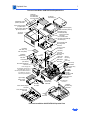
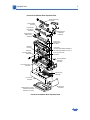
1
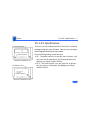
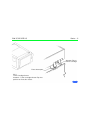
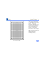
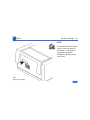
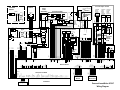
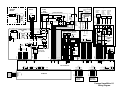
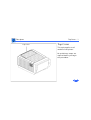
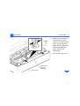
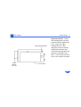
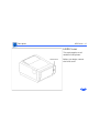
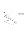
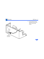
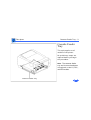
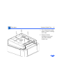
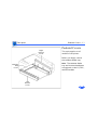
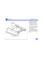
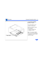
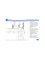
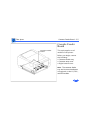
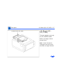
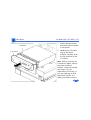
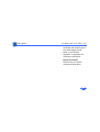
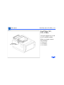
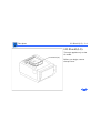
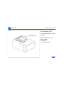
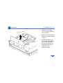
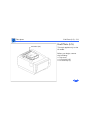
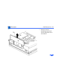
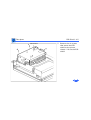
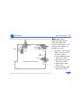
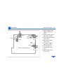
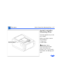
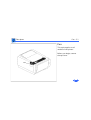
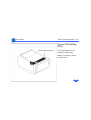
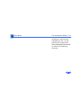
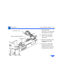
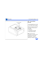
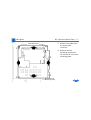
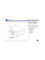
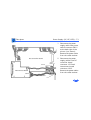
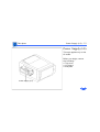
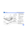
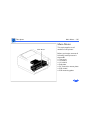
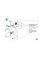
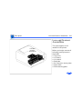
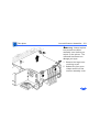
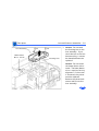
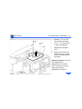
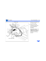
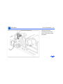
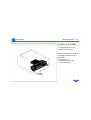
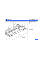
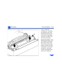
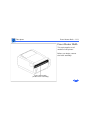
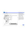
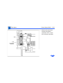
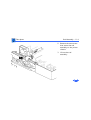
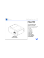
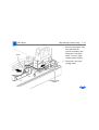
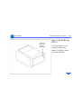
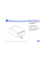
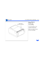
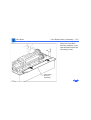
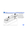
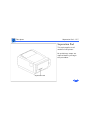
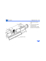
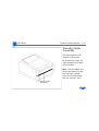
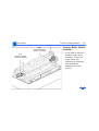
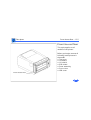
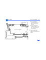
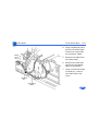
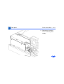
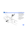
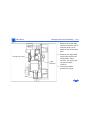
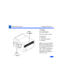
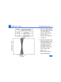
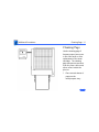
K Service Source
PLW SC/NT/NTR/LS
Personal LaserWriter SC, Personal LaserWriter NT,
Personal LaserWriter NTR, Personal LaserWriter LS,
Personal LaserWriter LS/L
K Service Source
Basics
PLW SC/NT/NTR/LS
Basics
Product Information - 1
Product Information
The printers covered in this manual are
• Personal LaserWriter SC
• Personal LaserWriter NT
• Personal LaserWriter NTR
• Personal LaserWriter LS
• Personal LaserWriter LS/L
Compatibility
Not all parts are compatible among the five models. Refer to
Illustrated Parts for compatibility cross references.
The cassette feeder tray and its associated parts are optional
on the LS, LS/L, and NTR models.
Basics
Paper Paths - 2
Paper Paths
There are four paper paths in the Personal LaserWriter.
Paper is fed from the cassette or multipurpose tray and
delivered to the face-down or face-up delivery trays.
Note: Face signifies image side. Default delivery is facedown at the top of the printer.
Basics
LS–LS/L Identification - 3
LS–LS/L Identification
I/O Board Bracket
Power Switch
Personal LaserWriter LS
Solid Rear Cover
Power Switch
Personal LaserWriter LS/L
The LS/L is a cost-reduced version of the LS but is sold and
packaged under the same LS name. Parts are not necessarily
interchangeable between the two models.
External distinguishing characteristics:
• LS: The power switch is on the left rear of printer; the
rear cover has an opening for an I/O board bracket and
displays the family number M2000.
• LS/L: The power switch is on the right rear of printer;
the rear cover is solid plastic and displays the family
number M2002.
Basics
Sensing System Theory - 4
Sensing System
Theory
PS12
PS502
PS11
PS501
PS13
PS901
There are six sensors in the
Personal LaserWriter: four
paper sensors and two
printer-open sensors. Each
consists of an actuator, a Ushaped photo interrupter,
and circuitry that communicates with the controller.
If the actuator is present
inside the U, the circuit
closes; if it is absent, the
circuit opens. In ready state
the appropriate circuit is
closed.
Basics
Sensing System Theory - 5
PS12
PS502
PS11
PS501
PS13
PS901
Paper sensors are actuated
as an arm or lever swings
against movement of paper.
Printer-open sensors are
actuated as the user shuts a
door or cover.
Illustrations on the
following cards show each
sensor as it would appear in
print ready state. Some
peripheral elements are
deleted for clarity.
PLW SC/NT/NTR/LS
Basics - 6
Actuator Tab on
Toner Cartridge
Photo Interrupter
PS11
Toner Cartridge Sensor
Actuator: Toner cartridge shutter flips into
position as front door closes.
PLW SC/NT/NTR/LS
Basics - 7
Photo
Interrupter
PS12
Delivery Unit Paper Sensor
Actuator: Sensing lever housed in fuser
assembly is tripped by paper exiting fuser.
Paper-Sensing Lever
PLW SC/NT/NTR/LS
Basics - 8
Photo
Interrupter
Paper-Sensing Lever
PS13
Pickup Unit Paper Sensor
Actuator: Sensing lever in feeder assembly
is tripped by paper entering feed cycle.
PLW SC/NT/NTR/LS
Basics - 9
Photo
Interrupter
PS501
Multipurpose Tray Sensor
Actuator: Sensing lever in multipurpose cable
assembly is tripped by manually fed paper.
Paper-Sensing Lever
(Shown in tripped position)
PLW SC/NT/NTR/LS
Basics - 10
Cover
Sensing
Arm
PS502
Face-Up Cover Sensor
Actuator: Sensing arm is tripped
by the closing of the face-up ocver.
Photo Interrupter
PLW SC/NT/NTR/LS
Basics - 11
Photo
Interrupter
PaperSensing Arm
PS901
Paper Cassette Sensor
Actuator: Sensing arm is tripped by the
insertion of loaded cassette tray.
Basics
Startup Test Pages - 12
Startup Test Pages
The Personal LaserWriter
SC, NT, and NTR generate a
startup test page 2 – 3
minutes after you switch on
the printer. The LS and LS/
L do not produce such a page.
In the NT and NTR the
startup test page also shows
unit-specific configuration
information. The following
pages describe each element
of the startup test pages.
PLW SC/NT/NTR/LS
Basics - 13
Ê
Printer Name
I/O Board
Type
Communication Protocol
RS-232 serial or AppleTalk
Fonts in ROM
Installed RAM
Version of ROM installed
Number of pages the I/O
board has produced
NT/NTR Startup Test Page
Basics
Startup Test Pages - 14
The Personal LaserWriter
SC test page consists of a line
matrix. The printer
generates a test page only if
you set its SCSI address to 7
prior to switching on the
printer. It continues to
print until it is out of paper.
Note: Be sure to set the SCSI
address back before
resuming printing.
SC Startup Test Page
Basics
Service Test Page - 15
Service Test Page
Successful printing of a
service test page confirms
print engine operation.
There are three variations
in how you run a service test
page, depending on the
model you are servicing.
Each involves using a pencil
or similar dowel-shaped
tool to depress the service
test button on the DC
controller board (or serial
controller on the LS/L).
Service Test Page
Basics
Service Test Page - 16
SC, NT, NTR
First remove the I/O board.
You can then access the test
button through the 1/4inch diameter opening in
the I/O shield.
SC, NT, NTR
Service Test Page
Basics
Service Test Page - 17
LS
First remove the I/O board
bracket. You can then access
the test button through the
1/4-inch diameter opening
in the end plate.
LS
Service Test Page
Basics
Service Test Page - 18
LS/L
First remove the test button
cover on the rear panel of
the printer. You can then
access the test button
through the opening in the
rear panel.
LS/L
Service Test Page
K Service Source
Specifications
PLW SC/NT/NTR/LS
Specifications
General - 1
General
Engine
Canon P110 engine
Printing Method
Electrophotography using single-component dry toner
Optical System
Semiconductor laser and a rotating dual-faced scanning mirror
Resolution
300 dpi
Imaging Languages
Supported
SC: QuickDraw
NT: PostScript, HP LaserJet Plus, and a subset of Diablo 630
NTR: PostScript, HP LaserJet Plus, and a subset of Diablo 630
LS: QuickDraw
LS/L: QuickDraw
Specifications
Intro Dates - 2
Intro Dates
SC and NT
July 1990
LS
March 1991
LS/L and NTR
March 1992
Specifications
Logic Board - 3
Logic Board
CPU
DRAM
SC: Motorola 68000 microprocessor (7.275 MHz)
NT: Motorola 68000 microprocessor (12 MHz)
NTR: N/A
LS: N/A
LS/L: N/A
SC: 1 MB
NT: 2 MB, expandable to 8 MB
NTR: 3 MB, expandable to 4 MB
LS: 512K, expandable to 1 MB
LS/L: 512K, expandable to 1 MB
Specifications
ROM
I/O
Logic Board - 4
SC: 32K
NT: 1.25 MB
NTR: 3 MB
LS: N/A
LS/L: N/A
SC: SCSI
NT: LocalTalk, RS-232, RS-422
NTR: LocalTalk, RS-232, RS-422, Centronics parallel
LS: RS-422
LS/L: RS-422
Specifications
Performance - 5
Performance
Printing Speed
4 pages per minute maximum; actual performance depends on the
application
Print Delivery
Face-down or face-up (manually selectable)
Life Expectancy
150,000 pages with no monthly page limit
Specifications
Paper - 6
Paper
Paper Weights
Cassette Sizes
Capacity In
Capacity Out
Cassette feed: 20 lb., single-sheet, photocopy bond
Manual feed: 20-28 lb., letterhead and colored stock, mediumweight transparency material, envelopes, and labels
US letter standard; legal, A4, B5, and envelope cassettes optional
Cassette: 250 sheets
Manual: 50/70 sheet capacities
Envelope cassette: 15 envelopes, minimum size 86 x 178 mm
(3.5 x 7 in.), maximum size 188 x 267 mm (7.4 x 10 in.)
Face-down tray: 50 sheets
Face-up tray: 20 sheets
Specifications
Built-In Fonts - 7
Built-In Fonts
SC, LS, and LS/L
NT
NTR
N/A
Times, Helvetica, Helvetica Narrow, Courier, Symbol, Palatino,
ITC Avant Garde, Gothic, ITC Bookman, New Century
Schoolbook, ITC Zapf Chancery, and ITC Zapf Dingbats
Times, Helvetica, Helvetica Narrow, Courier, Symbol, Palatino,
ITC Avant Garde, Gothic, ITC Bookman, New Century
Schoolbook, ITC Zapf Chancery, ITC Zapf Dingbats, and IBM PC
Graphics Extended Character Set (ECS)
Specifications
Environmental - 8
Environmental
Temperature
50-90.5° F (10-32.5° C)
Humidity
20-80% relative humidity
Noise Level
Printing: Under 53 dB(A)
Standby: Under 43 dB(A)
Specifications
Electrical - 9
Electrical
Line Voltage
US/Japan: 100/115 V, 50/60 Hz
Europe/Australia: 220/240 V, 50 Hz
Power Consumption
600 W maximum (100/115 V)
550 W maximum (220/240 V)
Specifications
Physical - 10
Physical
Dimensions
Height: 8 in. (20.3 cm), 9.8 in. (24.8 cm) with cassette feeder
Width: 15 in. (38 cm)
Weight
SC, NT, and NTR: 32 lb. (15 kg)
LS and LS/L: 31 lb. (14.5 kg)
K Service Source
Troubleshooting
PLW SC/NT/NTR/LS
Troubleshooting
Status Panel LEDs - 1
Status Panel LEDs
On the next page is an illustration that shows the possible LED
patterns that can occur with the Personal LaserWriter.
Note: Refer to "Print Engine Check" in Flowcharts for full
troubleshooting paths.
Troubleshooting
Status Panel LEDs - 2
LS and LS/L display only
these configurations
(see “LS Error Messages”)
Ready
Paper
Out
Paper
Jam
Front Access Door Open
No Toner Cartridge
or Face-Up Cover Open
(see PS11/PS502 in “Sensing
System Theory” in Basics.)
I/O Board
Alternating
FLASH
Fuser or
Laser/Scanner
Simultaneous
FLASH
Troubleshooting
Capacitor Discharge - 3
Capacitor Discharge
When there is a failure of the fusing system, the DC controller
board shuts off current to the fuser roller heater and charges
capacitor C212 to prevent overheating (C209 on the LS/L serial
controller board).
DC Controller Board
(SC, NT, NTR, LS)
C212
C209
Serial Controller
(LS/L)
Troubleshooting
Capacitor Discharge - 4
Before you can use the printer again, you must switch the power
off and wait 3 minutes for the capacitor to discharge. If you do not
want to wait, you can manually discharge the capacitor as
described below.
Remove the top cover, locate the capacitor described on the
previous page, and carefully jumper the two wires at the base of
the capacitor as shown on the next page.
Note: Remove the I/O board and/or shield if you are servicing an
SC, NT, or NTR. Remove the PCB shield if you are servicing an LS/
L.
Caution: Take care not to damage the board tracings or the
components around the capacitor. There are many different tools
that can be used to discharge the capacitor: a flat blade
screwdriver, paper clip, or aluminum foil doubled over. The tool
illustrated is a length of lead solder. It has the advantage of being
ductile and is less apt to damage the controller board.
Troubleshooting
Capacitor Discharge - 5
Capacitor C212
(C209 on LS/L)
Troubleshooting
LS Error Messages - 6
LS Error Messages
The SC, NT, and NTR display errors through status panel readouts
(see “Status LEDs”). The LS and LS/L display errors through
alert dialogs on the host computer.
For other hardware-related messages, go to “Print Engine
Check.” For non-hardware error messages, follow the prompt
given, or call the Apple Technical Assistance Center.
Note: If you are having communication problems with an LS,
make sure that you have used the installer to load the printer
driver.
Troubleshooting
Roller Diameters - 7
Roller Diameters
Repetitive printing defects can often be isolated by measuring the
tracking left by rollers. On the next page is a diagram that shows
all the rollers in the Personal LaserWriter that come into contact
with paper. The dimension given is the distance between tracks.
Troubleshooting
Roller Diameters - 8
Toner Cartridge Rollers
1.5" (38 mm): primary charging roller
2.0" (51 mm): developer roller
3.7" (94 mm): photosensitive drum
Fuser Assembly
2.15" (54 mm): lower fuser roller
2.9" (74 mm): upper fuser roller
Other Rollers
1.9" (49 mm): paper feed roller
2.05" (52 mm): transfer roller
Troubleshooting
Drum Check - 9
Drum Check
Interrupting a print cycle and inspecting the photosensitive drum
can help isolate the cause of print quality problems. If the image
on the surface of the drum exhibits the same problem as the
printed page, the fault is before the drum, probably somewhere in
the scanning system.
If the image on the drum is okay, the fault is after the drum,
probably in the fuser assembly, transfer roller, or high-voltage
power supply.
Note: Refer to “Roller Diameters” in this chapter for further
quick-check troubleshooting tips.
Troubleshooting
Flowcharts - 10
Flowcharts
The flowcharts for this manual are contained in an interactive file
called “PLW SC/NT/NTR/LS Flowcharts.” This file has been
derived from the original version of Service Source but is a
standalone self-launching application. To launch this file, click
the button below..
Display Panel
/SBSY
/RDY
/BD
LED 2
LED 3
+5V
+5V
+5V
+5V
+5V
B6
B7
B8
B9
B10
B11
B12
B13
B14
B15
B16
Interconnect PCB
7
7
Laser
Driver
GND
RDYNH
4
5
6
10
TSTPNT
OB
OB
SL901
12
6
A
GND
C
SL902
5
6
4
3
7
3
2
1
J905
Cassette
Pick-Up
Roller
Clutch
Solenoid
11
OA
COB
2
1
4
5
1
2
3
J902
Cassette
Feed
Roller
Clutch
Solenoid
TSTPE
+8V
APCIN
9
OA
COA
Density
Adj.
PCB
TSS
TSC
9
8
7
R901
Cassette Size
Sensing
Switches
8
J210
9
8
7
SW901
5
6
Q902
7
GND
OPMD
OPCD
OPPOUT
SW902
4
R904
PS901
LPC
+12V
+24V
2
5
6
SW903
J152
3
R903
Cassette
Paper
Sensor
3
+5V
1
OPSIZ0
OPSIZ1
4
3
2
1
HVT3
HVT2
HVD
HVT
OPSIZ2
+5V
J901
10
9
RT105
J602
2
Primary Charging
Roller
Developing
Cylinder
2
VR701
1
1
J205
10
9
D. Development
FT101
TB601
Multi-Purpose
Tray
Paper
Sensor
+5V
+24V
HVT3
HVT2
HVT1
RT104
4
Transfer
Charging
Roller
+12V
SCNON
SCNTAC
SCNCLK
GND
8
7
T. Transfer
SG
EP-L Cartridge
J207
2
1
2
1
4
4
3
5
3
6
5
8
7
FM11
HVTI
HVD
HVDC
+8V
HVDC
VR
HVAC
GND
RT504
5
6
4
3
RT103
RT102
5
6
4
3
1
J602
D502
+8V
VR
GND
HVAC
2
P. Primary
Exhaust Fan
2
Fan
Driver
+24V
Cartridge Sensor
Delivery Paper Sensor
+8V
6
J601
1
Delivery
Unit
Door
Open
Sensor
1
J206
+24V
PS502
GND
Optical Fiber
VDOUT
A
GND
C
A
GND
C
Drum
6
DC Controller
LSRPWR
-3
-2
J504
-1
3
2
Fuser Assembly
J203
5
6
5
6
2
3
A
G
C
J5802
2
Front Access Door
J301
4
4
J204
Pick-up Unit
Paper Sensor
APCIN
R104
GND
+5V
9
9
SSR101
3
8
8
J701
1
2
3
J503
1
D501
RT505
3
7
7
R702
2
3
R701 TB703
J13
1 1
PS12
GND
5
6
5
6
A
G
C
PS501
VR
CNTD
4
4
2
3
1
PS11
FMDRV
POSNS
DOSNSE
2
3
3
TH1
3
Q101
2
RT503
3
N
1
3B
2
SW101
1
Door
Switch
2
3A
1
SQ101
TB702 J12
H1
+8V
+5V
+12V
TB701
1
3 RT502
J213
TB504 3
TB503 1
Fixing
DC PCB
9
10
8
7
6
5
TB502
GND
DOA
DOSNSE
GND
POA
4
Pick-Up SL501
Roller
Clutch
Solenoid
POUT
3
TP2
2
/PCLK
B5
GND
TP1
1
/PRNT
B4
2
1 RT501
2
/CPRDY
2
1
1B
PFDRV
FSRTH
J209
J501
1
/CMD
B3
+24V
1
2
J101
2
5
6
3
J11
TB501
J202
Reserved
R103
R102
TB104
TB106
TB103
YB105
1A
TSTPNT
4
N.C.
N.C.
CMD
CPRDY
TB108
TB107
VZ101
R101
Fuser
PCB
Assembly
J401
Reserved
GND
A12
B2
Reserved
A11
PRNT
PS13
PCLK
1 TB109-1
GND
LED 1
A10
A
GND
2 TB109-2
B1
LED Power
A9
SBSY
3
3
1
2
GND
/PPRDY
A8
J302
L102
A16
/TOP
A7
2
2
+5V
PFA
FSRDRV
RDY
C
ACL
1
J102
BOO
J14
J208
ACH
1
C104
A15
/STS
A6
PFSNS
GND
FSRDRV
+5V
GND
RT101
RESET
Y
9
+12V
GND
Door
Switch
PRFD
BL
BR
7
8
+24V
C103
GND
/CBSY
A5
OR
6
L101
A14
Reserved
A4
BL
5
SW11
GND
/VDO
A3
R
4
L101
CCLK
FSRDRV
+5V
GND
+12V
GND
+24V
+24V
C102
Power
Switch
A13
/CCLK
A2
VDOI
N.C.
CBSY
STS
TOP
PPRDY
SG
FU1
/PRFD
J304
LED 3
LED 2
A1
A2
A3
A4
A5
A6
A7
A8
A9
A10
B1
B2
B3
B4
B5
B6
B7
B8
B9
B10
C102
TB102
LED 1
LED Power
BL
R
Power Supply
Unit
A1
4
4
+5V
3
+5V
3
1
GND
2
2
GND
1
3
2
4
2
3
IL101
GND
C101
TB102
1
J301
L
C101
BK
J303
GND
GND
+24V
CB101
BL
CB101
1
J212
TB101
GND
GND
GND
+5V
+5V
BK
BL
BL
BR
BR
220/240V
Models
Cassette Paper Feeder
Q901
R902
Cassette
Paper
Feeder
PCB
Main Motor
M1
Scanner
Motor Unit
I/O Board
Personal LaserWriter SC/NT
Wiring Diagram
Display
Panel
1
1
2
2
3
3
4
4
LED 1
LED 2
LED Power
5
6
7
5
6
7
Laser
Driver
5
4
3
2
1
5
4
3
2
1
+12V
+24V
+8V
APCIN
9
10
TSTPNT
OB
OB
SL901
12
6
7
A
GND
C
SL902
5
6
4
3
2
1
4
5
3
2
1
J905
Cassette
Pick-Up
Roller
Clutch
Solenoid
11
COB
OA
OA
COA
9
8
1
2
3
J902
Cassette
Feed
Roller
Clutch
Solenoid
TSTPE
TSS
TSC
J210
9
5
6
7
SW901
R901
Cassette Size
Sensing
Switches
8
GND
Density
Adj.
PCB
LPC
RDYNH
8
7
SW902
4
Q902
7
5
6
4
OPMD
OPCD
OPPOUT
SW903
J152
3
R904
RT105
J602
2
PS901
GND
+5V
2
5
6
4
3
R903
D. Development
Cassette
Paper
Sensor
3
1
OPSIZ0
OPSIZ1
OPSIZ2
2
1
HVT3
HVT2
HVD
HVT
+5V
J901
10
9
HVT1
FT101
TB601
Primary Charging
Roller
Developing
Cylinder
2
1
VR701
J205
10
9
1
+5V
+24V
HVT3
HVT2
8
7
RT104
4
Transfer
Charging
Roller
+12V
SCNON
SCNTAC
SCNCLK
GND
8
7
T. Transfer
SG
EP-L Cartridge
J207
6
6
HVTI
HVD
HVDC
+8V
HVDC
VR
HVAC
GND
FM11
5
6
4
3
RT103
MultiPurpose
Tray
Paper
Sensor
5
6
4
3
1
J602
RT102
+8V
VR
GND
HVAC
2
P. Primary
Exhaust Fan
2
Fan
Driver
+24V
Cartridge Sensor
Delivery Paper Sensor
+8V
6
J601
1
Delivery
Unit
Door
Open
Sensor
1
J206
+24V
Optical Fiber
PS502
GND
VDOUT
DC Controller
LSRPWR
J204
Fuser Assembly
Drum
J203
4
4
APCIN
GND
+5V
A
GND
C
Front Access Door
J301
3
2
I/O Board
3
Pick-up Unit
Paper Sensor
1
R104
2
SSR101
1
PS12
-3
-2
A
GND
C
PS501
2
3
A
J504
-1
3
2
RT505
J202
9
9
J701
1
G
C
RT504
VR
8
8
2
3
J5802
D502
GND
7
7
R702
2
3
R701 TB703
J13
1 1
J503
1
2
TP1
CNTD
5
6
5
6
PS11
FMDRV
4
4
A
D501
TH1
G
C
RT503
POSNS
2
3
1
3
TP2
DOSNSE
3
3
2
3
1
2
H1
+8V
+5V
Q101
2
3B
1
SW101
2
3A
1
N
TB702 J12
SQ101
+12V
TB701
3 RT502
J213
1
TB502
TB504 3
TB503 1
Fixing
DC PCB
9
10
8
7
1 RT501
GND
DOA
DOSNSE
6
5
Pick-Up SL501
Roller
Clutch
Solenoid
GND
POA
2
4
J501
POUT
1 TB109-1
3
Fuser
PCB
Assembly
GND
4
2
TB501
1
J209
1
2
5
6
3
J11
SW11
PFDRV
FSRTH
+24V
1B
N.C.
2 TB109-2
R103
2
J101
TB104
TB106
TB103
YB105
1A
N.C.
1
2
+5V
C104
CMD
Door
Switch
CPRDY
R102
L102
PRNT
TB108
C103
PCLK
A
GND
PS13
SBSY
3
3
TB107
VZ101
R101
L101
RDY
2
2
+5V
PFA
C
FSRDRV
1
ACL
1
FU1
BD
PFSNS
GND
J14
J208
FSRDRV
+5V
GND
J102
N.C.
Y
9
+12V
GND
RT101
PRFD
BL
BR
7
8
+24V
ACH
CCLK
OR
6
L101
VDO
BL
5
Power Supply
Unit
N.C.
FSRDRV
+5V
GND
R
4
Door
Switch
CBSY
STS
TOP
+12V
GND
+24V
C102
C101
Power
Switch
J401
LED 3
+24V
TB102
PPRDY
SG
C102
BK
A1
A2
A3
A4
A5
A6
A7
A8
A9
A10
B1
B2
B3
B4
B5
B6
B7
B8
B9
B10
IL101
BL
R
L
2
3
TB101
C101
CB101
GND
GND
GND
+24V
BK
BL
CB101
1
J212
TB102
J803
J301
GND
220/240V
Models
Cassette Paper Feeder
Q901
R902
Cassette
Paper
Feeder
PCB
Main Motor
M1
Scanner
Motor Unit
Personal LaserWriter LS
Wiring Diagram
K Service Source
Take Apart
PLW SC/NT/NTR/LS
Take Apart
Top Cover
Top Cover - 1
Top Cover
This topic applies to all
models of the printer.
No preliminary steps are
required before you begin
this procedure.
Take Apart
Top Cover - 2
1
2
Open the front access
door.
Note: There is a pin on
the inside of the rear
panel that seats in a
notch in the chassis. You
must shimmy the cover
about an inch toward the
rear of the printer to
unseat this pin before
you can lift off the cover.
Remove the two screws
and lift off the top cover.
Take Apart
Front Cover - 3
Front Cover
This topic applies to all
models of the printer.
No preliminary steps are
required before you begin
this procedure.
1
Front Cover
Open the front access
door.
Take Apart
Front Cover - 4
2
Holding
Tab
3
Front Cover
Face-Down
Delivery
Assembly
Remove the two screws
that secure the front
cover to the front access
door. Lift up the facedown delivery assembly
and using needlenose
pliers release the
holding tab.
Lift off the front cover.
Take Apart
Front Cover - 5
Right Holding Notch
Screw
Mount
Grooves
Front Door
Replacement Note: Lower
the multipurpose tray and
remove the face-up delivery
tray. Insert the right
holding tab first, then
swing the cover to the left,
making sure that the two
screw mounts align with the
grooves in the side of the
door. Press firmly until the
front cover snaps into place.
Take Apart
LED Cover - 6
LED Cover
This topic applies to all
models of the printer.
LED Cover
Before you begin, remove
the front cover.
Take Apart
LED Cover - 7
1
LED Cover
Remove the two screws
that secure the LED
cover to the front access
door.
Take Apart
LED Cover - 8
2
LED Cable
Connector
Lift off the LED cover
and disconnect the LED
cable from the LED
holder.
Take Apart
Cassette Feeder Tray - 9
Cassette Feeder
Tray
This topic applies to all
models of the printer.
No preliminary steps are
required before you begin
this procedure.
Note: The cassette feeder
tray and its associated parts
are optional on the LS, LS/L,
and NTR models.
Cassette Feeder Tray
Take Apart
Cassette Feeder Tray - 10
1
2
Cassette
Feeder
Tray
Turn the printer upside
down so that it is resting
on its top.
Remove the four
mounting screws and
lift off the cassette
feeder tray.
Take Apart
Pedestal Covers - 11
Right
Bottom
Cover
Pedestal Covers
This topic applies to all
models of the printer.
Before you begin, remove
the cassette feeder tray.
Note: The cassette feeder
tray and its associated parts
are optional on the LS, LS/L,
and NTR models.
Cassette
Stop
Cover
Left
Bottom
Cover
Take Apart
Pedestal Covers - 12
1
Cassette Stop Cover
Spring
Unhook the spring from
the cassette feeder tray,
and remove the cassette
stop cover.
Take Apart
Pedestal Covers - 13
2
Cassette
Microswitches
3
Right Bottom Cover
Caution: Be careful not
to damage the cassette
microswitches when
removing or replacing
the right bottom cover.
If you need to take apart
the right bottom cover,
remove the three
screws that secure it to
the cassette feeder tray.
Lift off the right bottom
cover.
Take Apart
Pedestal Covers - 14
4
Left Bottom Cover
5
If you need to take apart
the left bottom cover,
remove the two screws
that secure it to the
cassette feeder tray.
Lift off the left bottom
cover.
Take Apart
Cassette Feeder Roller Shaft - 15
Cassette Feeder
Roller Shaft
This topic applies to all
models of the printer.
Before you begin, remove
the following:
• Cassette feeder tray
• Pedestal covers
Note: The cassette feeder
tray and its associated parts
are optional on the LS, LS/L,
and NTR models.
Cassette Feeder Roller Shaft
Take Apart
Cassette Feeder Roller Shaft - 16
1
Feeder
Roller
Shaft
E-Ring
White
Gears
2
Using a small
screwdriver or gripring pliers, remove the
E-rings at each end of
the feeder roller shaft
(opposite end not
shown).
Slide off the two white
gears.
Take Apart
Cassette Feeder Roller Shaft - 17
3
4
Feeder
Roller
Shaft
Roller
Clamp
Holding Pin
Remove the holding pin.
Unhook the three plastic
feeder roller clamps
(rightmost clamp is
shown).
Take Apart
Cassette Feeder Roller Shaft - 18
5
Feeder
Roller
Shaft
Bushing
Slide the bushings off
each end of the feeder
roller shaft (opposite
end not shown) and
remove the shaft from
the cassette feeder tray.
Take Apart
Cassette Pickup Roller Shaft - 19
Cassette Pickup
Roller Shaft
This topic applies to all
models of the printer.
Before you begin, remove
the following:
• Cassette feeder tray
• Pedestal covers
Cassette Pickup
Roller Shaft
Note: The cassette feeder
tray and its associated parts
are optional on the LS, LS/L,
and NTR models.
Take Apart
Cassette Pickup Roller Shaft - 20
Pickup Roller
Shaft
Pickup Clutch Assembly
Setscrew
E-Ring
1
2
Using a small
screwdriver or gripring pliers, remove the
E-rings at each end of
the pickup roller shaft
(opposite end not
shown).
Note: Do not lose the
small metal holding pin
mentioned in the
following step. You will
need the pin when
replacing the pickup
roller.
Using a 1.5 mm Allen
wrench, loosen the
setscrew and remove the
Take Apart
Cassette Pickup Roller Shaft - 21
clutch assembly. The
holding pin from the
roller shaft will fall into
your hand.
Take Apart
Cassette Pickup Roller Shaft - 22
Pickup Roller
Shaft
3
Bushing
Slide the bushings off
each end of the pickup
roller shaft (opposite
end not shown) and
remove the shaft from
the cassette feeder tray.
Take Apart
Cassette Pickup Roller Shaft - 23
0.2 mm
Pickup Roller
Pickup Clutch Assembly
Replacement Note: When
replacing the pickup roller
shaft, give special care to
the following:
• Rotate the roller shaft
so that the crescentshaped pickup rollers
protrude through the
sheet metal.
• Be careful not to let
the holding pin slide
out of the shaft when
sliding the pickup
roller clutch onto the
roller shaft.
• Place a 0.2-mm
thickness gauge
between the cassette
Take Apart
Cassette Pickup Roller Shaft - 24
pickup roller clutch
and the E-ring.
• Adjust the setscrew so
that the distance
between the pickup
roller clutch and the
E-ring is 0.2 mm.
Then tighten the
setscrew into position.
Take Apart
Cassette Feeder Board - 25
Cassette Feeder
Board
Cassette Feeder
Board
This topic applies to all
models of the printer.
Before you begin, remove
the following:
• Cassette feeder tray
• Cassette stop cover
• Right bottom cover
Note: The cassette feeder
tray and its associated parts
are optional on the LS, LS/L,
and NTR models.
Take Apart
Cassette Feeder Board - 26
1
Cassette Feeder Board
2
3
J902
Cassette Feeder Tray
Remove the four black
screws that secure the
cassette feeder board to
the feeder tray.
Disconnect connector
J902.
Remove the cassette
feeder board from the
cassette feeder tray.
Take Apart
I/O Board (SC, NT, NTR)
I/O Board (SC, NT, NTR) - 27
I/O Board (SC,
NT, NTR)
This topic applies to the only
SC, NT, and NTR models.
Before you begin, remove
the top cover.
Note: If the I/O board is
removed from the printer,
the LEDs no longer function.
Take Apart
I/O Board
I/O Shield
I/O Board (SC, NT, NTR) - 28
1
2
Loosen the two screws
that secure the I/O board
to the shield.
Handling the I/O board
only by the metal
bracket, carefully slide
the I/O board out of the
I/O shield.
Note: Before returning an
I/O board to Apple, remove
the metal connector
bracket. Keep this bracket
and install it on the
replacement I/O board. If
you are replacing an NTR
board that has Rev. 4.0
ROMs, you need to remove
Take Apart
I/O Board (SC, NT, NTR) - 29
the ROMs and install them on
the replacement board.
Refer to “NTR ROM
Upgrade” in Upgrades for
complete information.
Replacement Note:
Reinstall the I/O board
component-side down.
Take Apart
I/O Shield (SC, NT, NTR) - 30
I/O Shield (SC,
NT, NTR)
I/O Shield
(SC, NT, NTR)
This topic applies only to the
SC, NT, and NTR models.
Before you begin, remove
the following:
• Top cover
• I/O board
Take Apart
I/O Shield (SC, NT, NTR) - 31
1
I/O Shield
Remove the five
mounting screws and
lift the I/O shield from
the chassis.
Take Apart
End Plate (SC, NT, NTR) - 32
End Plate (SC,
NT, NTR)
This topic applies only to the
SC, NT, and NTR models.
End Plate
(SC, NT, NTR)
Before you begin, remove
the following:
• Top cover
• I/O board
• I/O shield
Take Apart
End Plate (SC, NT, NTR) - 33
1
End Plate
Remove the four
mounting screws and
lift the end plate out of
the chassis.
Take Apart
I/O Shield (LS) - 34
I/O Shield (LS)
I/O Shield (LS)
This topic applies only to the
LS model.
Before you begin, remove
the top cover.
Take Apart
I/O Shield (LS) - 35
1
I/O Shield
Remove the seven screws
that secure the I/O
shield and lift the I/O
shield from the printer.
Take Apart
I/O Board (LS) - 36
I/O Board (LS)
I/O Board (LS)
This topic applies only to the
LS model.
Before you begin, remove
the following:
• Top cover
• I/O shield (LS)
Take Apart
I/O Board
I/O Board (LS) - 37
J803
1
2
3
Disconnect the cable
from connector J803 on
the I/O board.
Remove the three screws
that secure the I/O board
in place.
Holding the board only
by the edges, disengage it
from the I/O bracket.
Gently lift straight up,
and disconnect the I/O
board from the
controller board.
Take Apart
End Plate (LS) - 38
End Plate (LS)
End Plate (LS)
This topic applies only to the
LS model.
Before you begin, remove
the following:
• Top cover
• I/O shield (LS)
• I/O board (LS)
Take Apart
End Plate (LS) - 39
1
Remove the five
mounting screws and
lift the end plate out of
the chassis.
Take Apart
PCB Shield - 40
PCB Shield
PCB Shield
This topic applies only to the
LS/L model.
Before you begin, remove
the top cover.
Take Apart
Duct Plate
PCB Shield - 41
1
Remove the two screws
that secure the duct plate
to the printer chassis.
Lift out the duct plate.
Take Apart
PCB Shield - 42
PCB Shield
2
Remove the six screws
that secure the PCB
shield to the printer
chassis. Lift out the PCB
shield.
Take Apart
Serial Controller - 43
Serial Controller
Serial Controller
This topic applies only to the
LS/L model.
Before you begin, remove
the following:
• Top cover
• PCB shield
Take Apart
Serial Controller - 44
Never
disconnect optical fiber
cable J204 when the
printer is powered on. Its
invisible laser beam can
damage your eyes.
±Warning:
J205
J206
J204
J203
J209
J208
J210
J202
1
J212
J213
J215
Serial Controller Board
Disconnect the following
cables from the serial
controller board:
• Laser assembly board
cable from J202
• Scanner motor board
cable from J203
• Optical fiber cable
from J204
• Cassette feeder board
cable from J205
Take Apart
Serial Controller - 45
J205
J206
J204
J203
J209
J208
J210
J202
J212
J213
J215
Serial Controller Board
• High-voltage power
supply cable from
J206
• Paper pickup sensor
cable from J208
• Fuser assembly cable
from J209
• Main motor cable
from J210
• DC power supply
cable from J212
• Fan-and-sensor
board cable from
J213
• Status light cable
from J215
Take Apart
Serial Controller - 46
2
Remove the four
mounting screws and
lift the board from its
mounting plate.
Take Apart
Serial Controller Mounting Plate - 47
Serial Controller
Mounting Plate
This topic applies only to the
LS/L model.
Serial Controller
Mounting Plate
Before you begin, remove
the following:
• Top cover
• PCB shield
Never
disconnect optical fiber
cable J204 when the
printer is on. Its invisible
laser beam can damage your
eyes.
±Warning:
Take Apart
Serial Controller Mounting Plate - 48
1
J205
J206
J204
J203
J209
J208
J210
J202
J212
J213
J215
Serial Controller Board
Disconnect the following
cables from the serial
controller board:
• Laser assembly board
cable from J202
• Scanner motor board
cable from J203
• Optical fiber cable
from J204
• Cassette feeder board
cable from J205
• High-voltage power
supply cable from
J206
• Paper pickup sensor
cable from J208
• Fuser assembly cable
from J209
Take Apart
Serial Controller Mounting Plate - 49
J205
J206
J204
J203
J209
J208
J210
J202
J212
J213
J215
Serial Controller Board
2
• Main motor cable
from J210
• DC power supply
cable from J212
• Fan-and-sensor
board cable from
J213
• Status light cable
from J215
Remove the cables from
the cable retainer near
J212.
Take Apart
Serial Controller Mounting Plate - 50
3
Remove the six screws
that secure the serial
controller mounting
plate to the chassis. Lift
the mounting plate out
of the printer.
Replacement Note: The
two metal tabs along the
rear mate into the
chassis on the LS/L
model.
Take Apart
Fan - 51
Fan
This topic applies to all
models of the printer.
Before you begin, remove
the top cover.
Fan
Take Apart
Fan - 52
J701
1
2
3
Remove the two fan
mounting screws.
Using small diagonal
cutters, carefullly cut
the tie-wrap that
secures the fan cable.
Disconnect fan
connector J701 from the
density-adjusting board.
Take Apart
Fan - 53
4
Unlatch the holding tab
and lift out the fan
bracket and the fan.
Replacement Note:
• Install the fan with
the label facing out.
• Place the gold-colored
grounding plate over
the fan bracket.
Holding
Tab
Take Apart
Sensor Mounting Plate - 54
Sensor Mounting
Plate
Sensor Mounting Plate
This topic applies to all
models of the printer.
Before you begin, remove
the top cover.
Take Apart
Sensor Mounting Plate - 55
1
Sensor
Mounting
Plate
2
Remove the two black
mounting screws and
washers and slightly lift
the sensor mounting
plate.
Disconnect connectors
J11 and J12 and lift out
the sensor mounting
plate.
Replacement Note:
Connect connectors J11
and J12 before seating
the sensor mounting
plate.
Connector
J12
Connector
J11
Take Apart
Density-Adjusting Board - 56
Density-Adjusting
Board
This topic applies only to the
SC, NT, NTR, and LS models.
Density-Adjusting
Board
Before you begin, remove
the following:
• Top cover
• I/O board
• I/O shield
• Sensor mounting plate
Note: In the LS/L, this is
called the “Fan-and-Sensor
Board” (see next topic).
Take Apart
Density-Adjusting Board - 57
Connector J213
1
2
Density-Adjusting Board
Connector
J701
3
4
Disconnect fan
connector J701 from the
density-adjusting board.
Disconnect connector
J213 from the DC
controller board.
Remove the cables from
all the various cable
retainers.
Remove the two black
mounting screws and
washers and lift out the
density adjusting board.
Take Apart
Fan-and-Sensor Board - 58
Fan-and-Sensor
Board
This topic applies only to the
LS/L model.
Fan-and-Sensor
Board
Before you begin, remove
the following:
• Top cover
• PCB shield
• Sensor mounting plate
Note: This board is similar
to the density-adjusting
board found in the SC, NT,
NTR, and LS models (see
previous topic). Density
adjustment is controlled in
Take Apart
Fan-and-Sensor Board - 59
software on the Personal
LaserWriter LS/L, so the
board at this location has
been redesigned and renamed
to reflect its remaining
functions.
Take Apart
Fan-and-Sensor Board - 60
Connector J213
1
2
Density-Adjusting Board
Connector
J701
3
4
Disconnect fan
connector J701 from the
fan-and-sensor board.
Disconnect connector
J213 from the serial
controller.
Remove the cables from
all the various cable
retainers.
Remove the two black
mounting screws and
washers and lift out the
fan-and-sensor board.
Take Apart
Interconnect Board - 61
Interconnect Board
Interconnect Board
This topic applies only to the
SC, NT, and NTR models.
Before you begin, remove
the following:
• Top cover
• I/O board
• I/O shield
Take Apart
Interconnect Board - 62
1
2
J303
Interconnect Board
J302
Carefully disconnect the
cables from interconnect
board connectors J302
and J303.
Remove the three black
mounting screws and
lift out the interconnect
board.
Take Apart
DC Controller Board - 63
DC Controller
Board
DC Controller
Board
This topic applies only to the
SC, NT, NTR, and LS models.
Before you begin, remove all
following items present in
the model:
• Top cover
• I/O board and shield
• Interconnect board
Note: Perform this
procedure only when you’re
replacing the controller
board itself. If you’re
replacing a deeper module,
Take Apart
DC Controller Board - 64
perform the “DC Controller
Mount Plate” topic.
J205
J206
J208 J209 J210
J204
J202
J203
Never
disconnect optical fiber
cable J204 when the
printer is powered on. Its
invisible laser beam can
damage your eyes.
±Warning:
1
DC Controller Board
J212
J213
Disconnect the following
cables from the DC
controller board:
• Laser assembly board
cable from J202
• Scanner motor board
cable from J203
• Optical fiber cable
from J204
Take Apart
J205
DC Controller Board - 65
J206
J208 J209 J210
J204
J202
J203
DC Controller Board
J212
J213
• Cassette feeder board
cable from J205
• High-voltage power
supply cable from
206
• Paper pickup sensor
cable from J208
• Fuser assembly cable
from J209
• Main motor cable
from J210
• DC power supply
cable from J212
• Density-adjusting
board cable from
J213
Take Apart
DC Controller Board - 66
2
3
Retainer
DC Controller Board
Interconnect Mount
Remove the cables from
the one board-mounted
retainer.
Remove the four
mounting screws and
lift the DC controller
board from its mounting
plate.
Replacement Note: Be
sure that the left rear
edge of the DC controller
board slides snugly into
the notch in the black
interconnect mount.
Take Apart
DC Controller Mount Plate - 67
DC Controller
Mount Plate
This topic applies only to the
SC, NT, NTR, and LS models.
DC Controller
Mount Plate
Before you begin, remove
the following:
• Top cover
• I/O board and shield
• End plate
Note: Perform this
procedure only when you’re
replacing the controller
board itself. If you’re
replacing a deeper module,
perform the “DC Controller
Take Apart
DC Controller Mount Plate - 68
Mount Plate” topic.
Never
disconnect optical fiber
cable J204 when the
printer is powered on. Its
invisible laser beam can
damage your eyes.
±Warning:
Note: The following step
does not apply to the
Personal LaserWriter LS.
J303
Interconnect Board
J302
1
Carefully disconnect the
cables from interconnect
board connectors J302
and J303.
Take Apart
DC Controller Mount Plate - 69
2
J205
J206
J208 J209 J210
J204
J202
J203
DC Controller Board
J212
J213
Disconnect the following
cables from the DC
controller board:
• Laser assembly board
cable from J202
• Scanner motor board
cable from J203
• Optical fiber cable
from J204
• Cassette feeder board
cable from J205
Take Apart
J205
DC Controller Mount Plate - 70
J206
J208 J209 J210
J204
J202
J203
DC Controller Board
J212
J213
• High-voltage power
supply cable from
J206
• Paper pickup sensor
cable from J208
• Fuser assembly cable
from J209
• Main motor cable
from J210
• DC power supply
cable from J212
• Density adjusting
board cable from
J213
Take Apart
DC Controller Mount Plate - 71
3
Cable Retainers
4
DC Controller
Mounting Plate
Remove the cables from
the three cable
retainers.
Remove the four
mounting screws and
lift out the DC controller
mounting plate.
Take Apart
Power Supply (SC, NT, NTR) - 72
Power Supply
(SC, NT, NTR)
This topic applies only to the
SC, NT, and NTR models.
Before you begin, remove
the following:
• Top cover
• I/O board
• I/O shield
• End plate
Power Supply
(SC, NT, NTR)
Take Apart
Power Supply (SC, NT, NTR) - 73
1
DC Controller Board
J212
Interconnect Board
J302
Cable Retainer
2
Disconnect the power
supply cable from power
switch connector SW11
at the back right of the
printer (not shown).
Remove the power cable
from the cable retainer.
Disconnect the power
supply cables from DC
controller board
connector J212 and
interconnect board
connector J302.
Remove the power cables
from the cable retainer.
Take Apart
Power Supply (SC, NT, NTR) - 74
3
4
J101
Disconnect connector
J101 by squeezing it and
then lifting up.
Remove the three
mounting screws and
lift out the power
supply.
Take Apart
Power Supply (LS) - 75
Power Supply (LS)
This topic applies only to the
LS model.
Before you begin, remove
the following:
• Top cover
• I/O board
• End plate
Power Supply (LS)
Take Apart
Power Supply (LS) - 76
1
2
DC Controller Board
J212
Disconnect the power
supply cable from power
switch connector SW11
(not shown). Remove
the power cable from the
cable retainer.
Disconnect the power
supply cable from DC
controller board
connector J212 and
remove the cable from
the cable retainer.
Take Apart
Power Supply (LS) - 77
3
4
J101
Disconnect connector
J101 by squeezing it and
then lifting up.
Remove the three
mounting screws and
lift out the power
supply.
Take Apart
Power Supply (LS/L) - 78
Power Supply (LS/
L)
This topic applies only to the
LS/L model.
Before you begin, remove
the following:
• Top cover
• PCB shield
Power Supply (LS/L)
Take Apart
Power Supply (LS/L) - 79
1
J212
Serial Controller Board
Retainer
Disconnect connector
J212 from the serial
controller and remove
the cable from the black
cable retainer near
J212.
Take Apart
Power Supply (LS/L) - 80
2
3
J101
Disconnect connector
J101 by squeezing it and
then lifting up.
Remove the three
mounting screws and
lift out the power
supply.
Take Apart
High-Voltage Power Supply - 81
High-Voltage
Power Supply
This topic applies to all
models of the printer.
High-Voltage
Power Supply
Before you begin, remove all
following items present in
the model:
• Top cover
• I/O board
• I/O shield
• End plate
• PCB shield
• Power supply
Take Apart
High-Voltage Power Supply - 82
1
J602
2
J601
3
High-Voltage
Cable Connector
High-Voltage Power Supply
Lift and draw out the
plastic tray containing
the high-voltage power
supply.
Disconnect connectors
J601, J602, and the
high-voltage cable
connector.
Remove the highvoltage power supply.
Note: The high-voltage
power supply does not ship
with the plastic tray or
grounding plate.
Replacement Note: Make
sure that the high-voltage
Take Apart
High-Voltage Power Supply - 83
cable connector nests
snugly in the guide tabs on
the rear of the contact
assembly.
Take Apart
Laser Assembly - 84
Laser Assembly
Laser Assembly
This topic applies to all
models of the printer.
Before you begin, remove all
following items present in
the model:
• Top cover
• I/O board
• I/O shield
• End plate
• DC controller mount plate
• PCB shield
• PCB mounting plate
Take Apart
Laser Assembly - 85
1
2
Do Not
Loosen
Do Not
Loosen
Connector J401
Laser Assembly
3
Disconnect connector
J401.
Caution: Never loosen
the two black screws at
the upper left and lower
right. If these screws
are loosened, the laser
assembly will lose
alignment and will have
to be replaced.
Remove the two recessed
mounting screws at the
lower left (1) and the
upper right (2) of the
laser assembly.
Lift out the laser
assembly.
Take Apart
Main Motor - 86
Main Motor
Main Motor
This topic applies to all
models of the printer.
Before you begin, remove all
following items present in
the model:
• Top cover
• I/O board
• I/O shield
• End plate
• DC controller mount plate
• PCB shield
• PCB mounting plate
Take Apart
Main Motor - 87
1
Cable
Retainer
2
Main Motor
3
Remove the two screws
that secure the motor to
the chassis.
Remove the wires from
the cable retainer.
Replacement Note: Make
sure to thread the wires
back into the cable
retainer.
Lift the main motor
straight up out of the
printer.
Take Apart
Lens and Scanner Assemblies - 88
Lens and Scanner
Assemblies
Lens and
Scanner
Assemblies
This topic applies to all
models of the printer.
Before you begin, remove all
following items present in
the model:
• Top cover
• I/O board
• I/O shield
• End plate
• DC controller mount plate
• PCB shield
• PCB mounting plate
Take Apart
Lens and Scanner Assemblies - 89
±Warning: Always replace
the protective scanner
assembly cover before you
switch on the printer. The
reflected laser beam can
damage your eyes.
1
2
Remove the large cover
retaining screw.
Release the four cover
clamps and lift off the
scanner assembly cover.
Take Apart
Lens and Scanner Assemblies - 90
3
Lens Assembly
Beam Detect
Mirror Screw
Focusing Lens
Caution: Do not touch
the focusing lens on the
lens assembly. If you
touch the lens or the lens
becomes dirty, it cannot
be cleaned and must be
replaced.
Caution: Do not loosen
the beam detect mirror
screw. The beam detect
mirror requires factory
alignment. If the screw
is loosened, the printer
must be replaced.
Remove the three black
screws and lift out the
lens assembly.
Take Apart
Lens and Scanner Assemblies - 91
4
J301
5
Caution: Do not touch
the scanner assembly
mirror. If it gets dirty,
it must be replaced.
Disconnect connector
J301.
Remove the three long
black mounting screws
and lift out the scanner
assembly.
Replacement Note: Perform
the “Registration
Adjustment” procedure
after installing a scanner
assembly (see the
Adjustments chapter).
Take Apart
Drive Assemblies - 92
Drive Assemblies
This topic applies to all
models of the printer.
Before you begin, remove all
following items present in
the model:
• Top cover
• Cassette feeder tray
Drive Assembly
Drum Drive
Assembly
Note: This procedure covers
the take apart of the drive
assembly and the drum drive
assembly.
Take Apart
Drive Assemblies - 93
1
2
Retainer
Pin
Grounding
Cable
Using needlenose pliers,
pull out the black cable
retainer pin that holds
the connector cables.
Remove the screw that
secures the grounding
cable.
Take Apart
Drive Assemblies - 94
Cable Clamp
3
4
Remove the cables from
the cable clamp.
Remove the three
mounting screws and
pull out the drive
assembly.
Replacement Note: Be
careful not to overtighten the three drive
assembly mounting
screws.
Drive Assembly
Take Apart
Drive Assemblies - 95
Drum Drive Assembly
5
Remove the three
mounting screws and
pull off the drum drive
assembly.
Take Apart
Feeder Assembly - 96
Feeder Assembly
This topic applies to all
models of the printer.
Before you begin, remove all
following items present in
the model:
• Top cover
• Cassette feeder tray
• Drive assembly
Feeder
Assembly
Take Apart
Feeder Assembly - 97
1
Access Panel
2
Latch
Open the front access
door.
Note: The access panel
mentioned below is
behind the right roller
of the feeder assembly
and has a very small
latch. The latch is hard
to see, but you can feel it
with your finger.
Pull the latch forward
and lift up the access
panel.
Take Apart
Feeder Assembly - 98
3
Sensor Connector
4
Disconnect the sensor
connector.
Note: There are holes
cut through the main
body block to facilitate
the screwdriver access
needed in the step below.
Remove the two feeder
assembly mounting
screws.
Take Apart
Feeder Assembly - 99
5
6
White Gear
Bushing
Remove the white gear
and black plastic bushing
from the end of the
feeder assembly shaft.
Lift up the feeder
assembly, pull it to the
left, and remove it.
Take Apart
Fuser Assembly - 100
Fuser Assembly
This topic applies to all
models of the printer.
No preliminary steps are
required before you begin
this procedure.
Fuser Assembly
Take Apart
Fuser Assembly - 101
1
Fuser Assembly
Face-Down
Delivery
Assembly
2
Open the front access
door.
Lift up the face-down
delivery assembly and
remove the five goldcolored screws that
secure the fuser
assembly to the front
access door.
Take Apart
Fuser Assembly - 102
3
Using a flatblade
screwdriver, carefully
pry between the fuser
assembly and the front
cover at the right edge
(A) while you pull out
the fuser assembly.
Replacement Note: Make
sure that the connector
pins at each end of the
front access door make
proper contact with the
connectors on the fuser
assembly. Improper
contact could cause the
fuser not to heat up.
Take Apart
Fuser Heater Bulb - 103
Fuser Heater Bulb
This topic applies to all
models of the printer.
Before you begin, remove
the fuser assembly.
Fuser Heater Bulb
(inside Fuser Assembly)
Take Apart
Fuser Heater Bulb - 104
1
Screw
Remove the gold-colored
screw and the washer
that secure the right side
of the heater bulb.
Take Apart
Fuser Heater Bulb - 105
2
Left Connector Bracket
Remove the two goldcolored screws on the
left end that secure the
left connector bracket to
the fuser assembly.
Take Apart
Fuser Heater Bulb - 106
3
Left Connector Bracket
4
Remove the two goldcolored screws on the
left rear face that secure
the left connector
bracket to the fuser
assembly (1 and 2).
Remove the screw and
washer that secure the
heater bulb cable to the
left connector bracket
(3).
Take Apart
Fuser Heater Bulb - 107
5
Left Connector Bracket
6
Retaining Spring
Remove the small
silver-colored screw
that secures the heater
bulb retaining spring to
the left connector
bracket.
Set aside the retaining
spring.
Take Apart
Fuser Heater Bulb - 108
7
J501
Left
Connector
Bracket
Remove the two black
screws that fasten
connector J501 to the
left connector bracket.
Take Apart
Fuser Heater Bulb - 109
8
Left Connector
Bracket
9
Fuser Bulb
Caution: Be careful not
to touch the surface of
the heater bulb when
removing it from the
fuser assembly. If you
accidentally touch the
bulb, clean it with
isopropyl alcohol.
Carefully pull the left
connector bracket and
heater bulb out of the
fuser assembly.
Remove the heater bulb
from the left connector
holder.
Take Apart
Fuser PCB Assembly - 110
Fuser PCB
Assembly
This topic applies to all
models of the printer.
Before you begin, remove
the following:
• Top cover
• Fuser assembly
• Face-down delivery
assembly
Fuser PCB Assembly
Take Apart
Fuser PCB Assembly - 111
1
2
3
J101
4
Fuser PCB Assembly
Rod
Assembly
Cable
Retainer
J501
5
Remove the screw that
fastens the rod assembly
to the front access door.
Remove the black screw
that secures connector
J501 to the front access
door.
Remove the black screw
that secures the cable
retainer to the front
access door. Lift out the
cable retainer.
Disconnect connector
J101.
Lift out the fuser PCB
assembly.
Take Apart
Rod Assembly - 112
Rod Assembly
This topic applies to all
models of the printer.
Before you begin, remove
the following:
• Top cover
• Fuser assembly
Rod Assembly
Take Apart
Rod Assembly - 113
1
Rod Assembly
Remove the screw that
fastens the metal end of
the rod assembly to the
front access door.
Take Apart
Rod Assembly - 114
2
3
Remove the two screws
that secure the rod
assembly to the printer
chassis.
Lift out the rod
assembly.
Take Apart
High-Voltage Contact Assy - 115
High-Voltage
Contact Assy
This topic applies to all
models of the printer.
HIgh-Voltage
Contact Assembly
Before you begin, remove all
following items present in
the model:
• Top cover
• I/O board
• I/O shield
• PCB shield
• End plate
• Power supply
• Fuser assembly
• Rod assembly
Take Apart
High-Voltage Contact Assy - 116
1
J602
2
High-Voltage
Cable
Pull out the plastic tray
from beneath the
scanner assembly and
disconnect connector
J602 from the highvoltage power supply.
Disconnect the highvoltage cable.
Take Apart
High-Voltage Contact Assy - 117
3
4
5
Mounting
Screw
Power Supply Cable
High-Voltage
Contact Assembly
Remove the contact
assembly mounting
screw.
Remove the power
supply cable from the
cable guide on the highvoltage contact
assembly.
Lift out the high-voltage
contact assembly.
Take Apart
Face-Up Delivery Drive - 118
Face-Up
Delivery
Drive
Assembly
Face-Up Delivery
Drive
This topic applies to all
models of the printer.
Before you begin, remove
the fuser assembly.
Take Apart
Face-Up Delivery Drive - 119
1
Remove the screw that
secures the face-up
delivery drive assembly
to the front access door.
Take Apart
Face-Up Delivery Drive - 120
2
Lift out the face-up
delivery drive assembly
and the white, 20-tooth
gear.
Take Apart
Face-Up Cover Assembly - 121
Face-Up Cover
Assembly
This topic applies to all
models of the printer.
Before you begin, detach the
face-up tray and remove
the fuser assembly.
Face-Up
Cover
Assembly
Take Apart
Face-Up Cover Assembly - 122
1
Tension Spring
Using needlenose pliers,
unhook the tension
spring that connects the
face-up cover to the
front access door.
Take Apart
Face-Up Cover Assembly - 123
2
3
Open the face-up tray by
pulling up on the green
latch on the outside of
the front access door.
Grip the bottom edge of
the face-up cover with
your fingertips and bend
it slightly to release the
holding pins at each end.
The face-up cover should
fall into your palms.
Take Apart
Face-Down Delivery Assembly - 124
Face-Down
Delivery Assembly
Face-Down
Delivery
Assembly
This topic applies to all
models of the printer.
Before you begin, remove
the fuser assembly.
Take Apart
Face-Down Delivery Assembly - 125
1
Face-Down
Delivery
Assembly
Swing the face-down
delivery assembly cover
open and remove the four
mounting screws.
Take Apart
Face-Down Delivery Assembly
Face-Down Delivery Assembly - 126
2
Lift out the face-down
delivery assembly.
Note: The deflector below
the face-down delivery
assembly is not mechanically connected to anything.
You can lift out the deflector
if it needs to be replaced.
Take Apart
Separation Pad - 127
Separation Pad
This topic applies to all
models of the printer.
No preliminary steps are
required before you begin
this procedure.
Separation Pad
Take Apart
Separation Pad - 128
1
2
Separation Pad
Open the front access
door.
Grasp the clear plastic
tab and pull the
separation pad straight
up and out of the printer.
Take Apart
Transfer Guide Assembly - 129
Transfer Guide
Assembly
This topic applies to all
models of the printer.
No preliminary steps are
required before you begin
this procedure.
Note: This procedure also
covers the removal of the
left and right transfer
roller mount assemblies
and the transfer roller.
Transfer Guide
Assembly
Take Apart
Transfer Guide Assembly - 130
Transfer Guide
Assembly
LS/L
1
2
Open the front access
door.
Note: On the LS/L the
grip on the right side
(A) has been closed into
a ring. In the following
step, you must first lift
the left end of the
assembly, then slide it
out and to the left.
Grasp each end of the
transfer guide assembly
and lift it out of the
printer.
Take Apart
Transfer Guide Assembly - 131
Transfer Guide
Assembly
LS/L
Replacement Note:
When replacing the
transfer guide assembly,
be sure that you snap the
black plastic grip into
the pickup roller shaft
(B).
Transfer Roller
1
If you want to remove
the transfer roller, pull
each end of the transfer
roller shaft from the
transfer guide assembly.
Take Apart
Transfer Guide Assembly - 132
Right
Transfer Roller
Mount Assembly
Left
Transfer Roller
Mount Assembly
Transfer Roller Mount
Assembly
1
If you want to remove a
transfer roller mount
assembly, remove the
single screw that
secures it to the access
door and lift the
assembly out of the
printer.
Take Apart
Pickup Roller Assembly - 133
Pickup Roller
Assembly
This topic applies to all
models of the printer.
Before you begin, remove
the transfer guide assembly.
Pickup Roller Assembly
Take Apart
Pickup Roller Assembly - 134
1
Pickup Roller
Assembly
Remove the three black
mounting screws and
lift out the pickup roller
assembly.
Take Apart
Front Access Door - 135
Front Access Door
This topic applies to all
models of the printer.
Front Access Door
Before you begin, remove all
following items present in
the model:
• Top cover
• I/O board
• I/O shield
• PCB shield
• Fuser assembly
• Front cover
• LED cover
Take Apart
Front Access Door - 136
Cable Retainer
J209
Note: Perform this
procedure only if you are
replacing the front access
door itself.
1
DC Controller Board
J303
Interconnect Board
2
Disconnect connector
J209 from the DC
controller board, or
from the serial
controller in the case of
the LS/L (not shown).
Disconnect the status
panel cable as described
below:
• SC, NT, NTR:
Disconnect connector
J303 on the
interconnect board.
Take Apart
Front Access Door - 137
Cable Retainer
J209
DC Controller Board
J303
Interconnect Board
3
• LS: Disconnect
connector J803 on
the I/O board (not
shown).
• LS/L: Disconnect
connector J215 from
the serial controller
(not shown).
Open the two cable
retainers and remove the
cables.
Take Apart
Front Access Door - 138
4
Black
Cord
Cover
5
6
7
Retainer
Pin
Grounding
Cable
Using needlenose pliers,
pull out the black cable
retainer pin that holds
the connector cables.
Remove the cables from
the cable clamp.
Remove the screw that
secures the grounding
cable to the chassis.
Using a small flat-blade
screwdriver, remove
the small black cord
cover.
Take Apart
Front Access Door - 139
8
Rod Assembly
Remove the screw that
fastens the metal end of
the rod assembly to the
front access door.
Take Apart
Front Access Door - 140
9
J101
Disconnect connector
J101 from the power
supply.
Take Apart
Front Access Door - 141
10 Locate the two plastic
pins at the hinge points
on either end of the front
access door (left pin is
illustrated here).
11 Using a jeweler’s
screwdriver, carefully
remove the plastic pins.
12 Lift away the front
access door.
Plastic Pin
Take Apart
Multipurpose Cable Assembly - 142
Multipurpose
Cable Assembly
This topic applies to all
models of the printer.
Multipurpose
Cable Assembly
Before you begin, remove all
following items present in
the model:
• Top cover
• I/O board and shield
• PCB shield
• Fuser assembly
• Front cover
• LED cover
• Transfer guide assembly
• Pickup roller assembly
• Right transfer roller
Take Apart
Multipurpose Cable Assembly - 143
mount
Note: The multipurpose
cable assembly is the
primary conduit of DC
power to the front access
door.
Take Apart
Multipurpose Cable Assembly - 144
1
2
Pickup Drive Gear
Cable
Retainer
3
J502
Remove the screw that
secures connector J502
and the small circuit
board to the front access
door.
Remove the large black
screw that secures the
black plastic cable
retainer. Pry loose and
lift out the cable
retainer.
Lift out the white
pickup drive gear.
Take Apart
Grounding Cable
Screw
Multipurpose Cable Assembly - 145
4
5
Solenoid Screw
Remove the screw that
secures the pickup
roller clutch solenoid.
Remove the screw that
secures the grounding
cable to the front door.
Take Apart
Multipurpose Cable Assembly - 146
6
Black
Cord
Cover
7
8
Retainer
Pin
Grounding
Cable
Using needlenose pliers,
pull out the black cable
retainer pin that holds
the connector cables.
Remove the screw that
secures the grounding
cable to the printer
chassis.
Using a small flat-blade
screwdriver, remove
the small black cord
cover.
Take Apart
Multipurpose Cable Assembly - 147
9
J101
Disconnect connector
J101 from the power
supply.
Take Apart
Multipurpose Cable Assembly - 148
Cable Retainer
J209
DC Controller Board
J303
Interconnect Board
10 Disconnect connector
J209 from the DC
controller board, or
from the serial
controller in the case of
the LS/L (not shown).
11 Disconnect the status
panel cable as described
below:
• SC, NT, NTR:
Disconnect connector
J303 on the interconnect board.
• LS: Disconnect
connector J803 on
the I/O board (not
shown).
Take Apart
Multipurpose Cable Assembly - 149
Cable Retainer
J209
• LS/L: Disconnect
connector J215 from
the serial controller
(not shown).
12 Open the two cable
retainers and remove the
cables.
DC Controller Board
J303
Interconnect Board
Take Apart
Multipurpose Cable Assembly - 150
Multipurpose
Cable Assembly
13 Remove the two black
screws that secure the
plastic sensor mount.
Lift up slightly on the
sensor mount.
14 Lift out the
multipurpose cable
assembly and sensor
mount.
Take Apart
Multipurpose Cable Assembly - 151
15 Note: You will need to
install the old paper
sensing lever into the
replacement cable
assembly.
Remove the paper
sensing lever at sensor
PS501 from the
multipurpose cable
assembly and set it aside.
Sensing Lever
Take Apart
Multipurpose Cable Assembly - 152
Paper-Sensing Arm
Paper-Sensing
Spring
Replacement Note: If you
removed the left transfer
roller mount assembly
prior to this procedure, the
paper-sensing arm may
have flipped loose when you
lifted off the sensor mount.
Replace the sensing arm and
spring as shown. The illustration shows the arm and
spring as they would look in
a functional print-ready
state.
K Service Source
Upgrades
PLW SC/NT/NTR/LS
Upgrades
NTR ROM Upgrade - 1
NTR ROM
Upgrade
U45 (L2)
U44 (L1)
U43 (L0)
ROMs
U63 (H2)
U62 (H1)
U61 (H0)
The NTR ROM Upgrade Kit
consists of six ROMs. The
following numbers are
imprinted on the six Rev.
4.0 ROMs:
• 341-0950
• 341-0951
• 341-0952
• 341-0953
• 341-0954
• 341-0955
If you are replacing a
customer’s NTR board,
check the ROMs. If they are
Upgrades
NTR ROM Upgrade - 2
Rev. 4.0 ROMs, you must
remove the ROMs and
install them on the
replacement board.
Replacement NTR boards do
not have Rev. 4.0 ROMs.
U45 (L2)
U44 (L1)
U43 (L0)
ROMs
U63 (H2)
U62 (H1)
U61 (H0)
Caution: Old ROMs must be
returned to Apple. Refer to
August 1993 Service
Notices for complete
information on the Personal
LaserWriter NTR ROM
Repair Extension Program.
K Service Source
Additional Procedures
PLW SC/NT/NTR/LS
Additional Procedures
Voltage Conversions - 1
Fuser
Assembly
110
220
Power
Supply
110
220
Voltage
Conversions
Before you begin, remove
the following:
• Top cover
• I/O board and shield
• End plate
Note: Personal LaserWriter
printers manufactured for
the USA and Japan operate at
line voltages of 110-115
volts. Those manufactured
for Europe or Australia
operate at line voltages of
220-240 volts.
Additional Procedures
Voltage Conversions - 2
1
Replace each of the components shown with a
corresponding one of the new voltage.
Additional Procedures
Nip Width Measurement - 3
Nip Width Measurement
Before you begin, remove the following:
• Top cover
• I/O board and I/O shield
You should perform the nip width measurement whenever
poor or irregular fusing occurs. This measurement shows
whether the fuser assembly rollers exert uniform pressure
on each page. If they don’t, replace the lower fuser roller.
If the problem persists, replace the fuser assembly.
Perform the procedure as described below.
1
2
Using a copy machine, make several copies of lettersize, all-black paper. Place the black sheets on the
multipurpose tray.
Switch on the printer and run a service test page (see
Basics).
Additional Procedures
Width
B
Nip Width Measurement - 4
Measure when upper
and lower rollers are hot
3
2-3 mm
A
Under 0.5 mm
C
Under 0.5 mm
A
Leading Edge of Paper
4
C
When the leading edge of
the paper appears at the
face-down delivery
rollers, switch off the
printer, wait 10
seconds, then switch on
the printer.
Measure the width of the
glossy band on the paper.
The band should be 2 – 3
mm wide at its center
and should extend no
more that .5 mm at the
top or bottom edge.
Note: If the
measurement fails to
meet specifications,
B
Additional Procedures
Width
B
Nip Width Measurement - 5
Measure when upper
and lower rollers are hot
2-3 mm
A
Under 0.5 mm
C
Under 0.5 mm
Leading Edge of Paper
A
C
B
replace the lower fuser
roller and perform the
test again. If the
measurement still does
not meet specifications,
replace the fuser
assembly.
Additional Procedures
Cleaning Page - 6
Cleaning Page
Use the cleaning page if
frequent paper jams occur
in the fuser area or after
replacement of the toner
cartridge. The cleaning
page removes excess toner
from the fuser rollers and
other rollers inside the
printer.
1
Place several sheets of
paper on the
multipurpose tray.
Additional Procedures
Cleaning Page - 7
2
3
Open the “Cleaning
page” file located on the
Personal LaserWriter
Installation Disk.
Select “Print” from the
File menu and “Manual
Feed” in the subsequent
dialog box and click OK.
The printer will print a
cleaning page.
Additional Procedures
Cleaning Page - 8
4
Place the cleaning page
face-up on the
multipurpose tray and
repeat the printing
procedure described on
the previous page.
K Service Source
Adjustments
PLW SC/NT/NTR/LS
Adjustments
-10
Registration Adjustment - 1
-8
-6
-4
Counterclockwise (-)
Before you begin, remove
the following:
• Top cover
• I/O board and I/O shield
-2
0
+2
+10 +8 +6 +4
VR201
Registration
Adjustment
Clockwise (+)
DC Controller Board*
*LS/L Serial Controller is similar
Perform the registration
adjustment whenever you
replace the DC controller
board (serial controller on
the LS/L) or the scanner
assembly motor.
1
Using a jeweler’s
screwdriver, reset
VR201 on the DC
Adjustments
-10
Registration Adjustment - 2
-8
-6
-4
Counterclockwise (-)
-2
3
0
+2
+10 +8 +6 +4
VR201
2
Clockwise (+)
DC Controller Board*
*LS/L Serial Controller is similar
controller board to “0”
Connect an AC power
cord to the printer and
switch on the printer.
Press the service test
page button three times
to make three service
test pages.
Adjustments
Leading Edge Registration Distance
Registration Adjustment - 3
4
Leading Edge of Paper
5
Test Page Pattern
Using a metric ruler,
measure the distance
from the leading edge of
the paper to the test
pattern for each print.
Calculate the average by
adding the measurements
and dividing by three.
Subtract the average
distance from 3.6 mm to
determine the correct
adjustment distance. For
example, if your average
distance is 2.4 mm, the
adjustment required is
1.2 mm (3.6 mm minus
2.4 mm).
Adjustments
Registration Adjustment - 4
(-) Counterclockwise
(Avg. distance > 3.6 mm)
Correction
Distance
(mm)
VR201
Setting
-0.48
-2
-0.24
-1
-0.72
-3
-0.96
-1.20
-1.44
-1.68
-1.92
-2.16
-2.40
-4
-5
-6
-7
-8
-9
-10
(+) Clockwise
(Avg. distance < 3.6 mm)
Correction
Distance
(mm)
VR201
Setting
+2.16
+9
+2.40
+10
+1.92
+8
+1.68
+1.44
+1.20
+0.96
+0.72
+0.48
+0.24
+7
+6
+5
+4
+3
+2
+1
6
7
8
Using the table to the
left, identify the
adjustment required to
return the registration
adjustment to 3.6 mm.
For example, with a
required adjustment of
1.2 mm, you would set
VR201 at +5 clockwise.
Adjust VR201 to the
value indicated.
Print three more test
pages. If the average
registration adjustment
is not 3.6 mm, repeat
this procedure.
Adjustments
Refurbishment Kit - 5
Refurbishment Kit
Since all major parts of the Personal LaserWriter are rated
to last the life of the printer itself, no refurbishment kit
exists for this family of printers.
K Service Source
Exploded View
PLW SC/NT/NTR/LS
Exploded View
1
Personal LaserWriter SC/NT/NTR/LS Exploded View
I/O Board
661-0566 (SC)
661-0565 (NT)
661-0725 (NTR)
I/O Shield
949-0326 (LS)
Stackability Guide
(NT/SC) 949-0261
Paper Support Plate
(LS) 949-0332
Paper Support Plate
(NT/SC) 949-0332
I/O Shield (upper)
949-0267 (SC/NT)
I/O Shield (lower)
949-0268 (SC/NT)
Interconnect PCB
922-0048
DC Controller PCB
661-0567 (SC/NT/NTR)
661-0650 (LS)
Top Cover
949-0283
DC Controller PCB
Mounting Plate
949-0271
Scanner Cover
971-0040
I/O Board
661-0631 (LS)
661-0725 (NTR)
I/O Board
Bracket (LS)
949-0314
Lens Assy
971-0041
Scanner Assy
661-0572
Laser Assy
661-0571
Main Motor
890-0426
Fan
720-0513
End Plate (LS)
(not offered)
Sensor
Mounting
Plate
890-1200
Drive Assy
890-0608
End Plate (SC/NT/LS)
948-0139
Drum Drive Assy
890-0609
Power Supply Unit
661-0569 (SC,NT,110/115 V)
661-0569 (NTR, 110/115 V)
661-0574 (SC,NT,NTR 220/240 V)
661-0636 (LS, 110/115 V)
661-0637 (LS, 220/240 V)
DensityAdjusting PCB
982-0039
Separation Pad
860-0295
High-Voltage
Power Supply
661-0573
Cover, Bottom (Right)
949-0825
Cover, Bottom (Left)
949-0825
Rod Assy
971-0046
High-Voltage
Contact Assy
892-8608
Feeder Assy
971-0044
Cassette
Feeder Assy
982-0035
Cassette
Stop
949-0274
Personal LaserWriter SC/NT/NTR/LS Exploded View
Exploded View
2
Personal LaserWriter Door Exploded View
Pickup Roller Assy
971-0045
Transfer Roller
870-0103
Left Transfer
Roller Mount
890-0607
Right Transfer
Roller Mount
890-0603
Multipurpose
Cable Assy
890-8605
Face-Down
Delivery Assy
971-0043
Deflector
971-0048
Fuser AC
Connector Cable
569-0049
Fuser Assy
661-0575 (SC,NT,NTR 220/240 V)
661-0568 (SC,NT,NTR 110/115 V)
Face-Up Cover Assy
949-0276
Face-Up Delivery
Drive Assy
971-0049
Front Access Door
949-0295
Face-Up Tray
922-0200
Front Cover
949-0293
Multipurpose Tray Assy
949-0279 (50 sheet)
949-0341 (70 sheet)
LED Cover
949-0294
Personal LaserWriter Door Exploded View