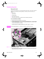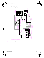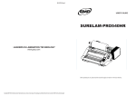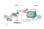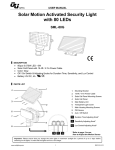
1
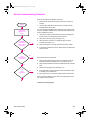
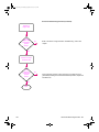
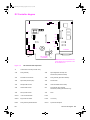
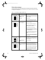
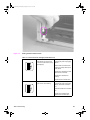
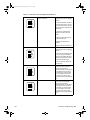
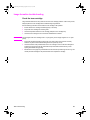
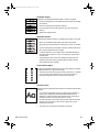
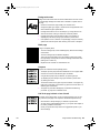
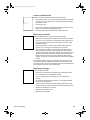
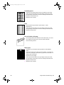
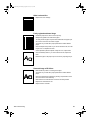
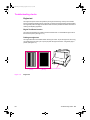
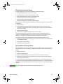
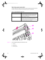
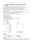
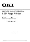
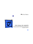
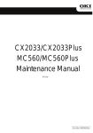
Service.book Page 115 Thursday, September 14, 2000 11:15 AM
7
Troubleshooting
Chapter contents
General troubleshooting flowchart. . . . . . . . . . . . . . . . . . . . . . . . . . . . . . . . . . . . . . . . . . . . . . . . 116
Paper path and components . . . . . . . . . . . . . . . . . . . . . . . . . . . . . . . . . . . . . . . . . . . . . . . . . . . . 118
DC Controller diagram. . . . . . . . . . . . . . . . . . . . . . . . . . . . . . . . . . . . . . . . . . . . . . . . . . . . . . . . . 119
Printer error troubleshooting . . . . . . . . . . . . . . . . . . . . . . . . . . . . . . . . . . . . . . . . . . . . . . . . . . . . 120
Priority of errors . . . . . . . . . . . . . . . . . . . . . . . . . . . . . . . . . . . . . . . . . . . . . . . . . . . . . . . . . . 120
Printer status messages . . . . . . . . . . . . . . . . . . . . . . . . . . . . . . . . . . . . . . . . . . . . . . . . . . . . 121
Service and error messages. . . . . . . . . . . . . . . . . . . . . . . . . . . . . . . . . . . . . . . . . . . . . . . . . 123
Image formation troubleshooting . . . . . . . . . . . . . . . . . . . . . . . . . . . . . . . . . . . . . . . . . . . . . . . . . 126
Check the toner cartridge . . . . . . . . . . . . . . . . . . . . . . . . . . . . . . . . . . . . . . . . . . . . . . . . . . . 126
Image defect examples . . . . . . . . . . . . . . . . . . . . . . . . . . . . . . . . . . . . . . . . . . . . . . . . . . . . . 127
Troubleshooting checks . . . . . . . . . . . . . . . . . . . . . . . . . . . . . . . . . . . . . . . . . . . . . . . . . . . . . . . . 133
Engine test . . . . . . . . . . . . . . . . . . . . . . . . . . . . . . . . . . . . . . . . . . . . . . . . . . . . . . . . . . . . . . 133
Half self-test functional check . . . . . . . . . . . . . . . . . . . . . . . . . . . . . . . . . . . . . . . . . . . . . . . . 134
Drum rotation functional check . . . . . . . . . . . . . . . . . . . . . . . . . . . . . . . . . . . . . . . . . . . . . . . 134
High-voltage power supply check . . . . . . . . . . . . . . . . . . . . . . . . . . . . . . . . . . . . . . . . . . . . . 135
Paper curl . . . . . . . . . . . . . . . . . . . . . . . . . . . . . . . . . . . . . . . . . . . . . . . . . . . . . . . . . . . . . . . 137
Troubleshooting tools. . . . . . . . . . . . . . . . . . . . . . . . . . . . . . . . . . . . . . . . . . . . . . . . . . . . . . . . . . 138
Paper path check . . . . . . . . . . . . . . . . . . . . . . . . . . . . . . . . . . . . . . . . . . . . . . . . . . . . . . . . . 138
Repetitive image defect ruler . . . . . . . . . . . . . . . . . . . . . . . . . . . . . . . . . . . . . . . . . . . . . . . . 139
Main wiring diagram . . . . . . . . . . . . . . . . . . . . . . . . . . . . . . . . . . . . . . . . . . . . . . . . . . . . . . . 140
EN
Chapter contents 115
Service.book Page 116 Thursday, September 14, 2000 11:15 AM
General troubleshooting flowchart
When the AC power is first applied to the printer:
l
Both the printer motor and the laser/scanner motor rotate for six
seconds.
l
All of the LEDs illuminate for one second; the “Ready” LED will
illuminate after three seconds.
START
If no error message is displayed, the Printer Door is firmly closed, and
the toner cartridge is installed, but the motor does NOT rotate when AC
power is applied to the printer:
AC Power is
applied to the
printer
Does the
Printer Motor
rotate in about
6 seconds?
No
1
Verify that AC power is present at the input power receptacle and
that the power cord is firmly inserted into the printer.
2
Verify that FU102 is not open. (See Figure 7-2.)
3
Verify that motor connector J1 is seated into J401 of the DC
Controller. (See Figure 7-2.)
4
Verify that the motor is correctly mounted to the printer chassis.
5
If all of these conditions are correct, replace the DC Controller PCA
and/or the motor.
Yes
Is the
Control Panel
functional?
No
If the Control Panel is not functional:
Yes
Is an
Error
displayed?
No
Yes
1
Verify that the Control Panel connector J9 is seated into both the
Control Panel and the Formatter PCA at J3. (See Figure 7-2.)
2
Verify that the Formatter PCA is firmly seated into the DC Controller
PCA.
3
Perform an Print Engine Test. (See Figure 7-4.)
4
If the engine test is successful, replace the Control Panel first, then,
if necessary, the Formatter PCA.
5
If the engine test is not successful, replace the DC Controller PCA.
If the control panel displays an error, refer to the appropriate section in
this chapter to correct the error.
Continued on following page.
116 Troubleshooting
EN
Service.book Page 117 Thursday, September 14, 2000 11:15 AM
General Troubleshooting Flowchart (continued)
Perform an
Engine Test
Is the
Engine Test
image being
printed
clearly?
No
Refer to the section “Image Formation Troubleshooting,” later in this
chapter.
Yes
Perform a Control
Panel Self-Test
Is the
Self-Test
image being
printed
clearly?
No
If the engine test produces a clear print image, yet a Self-Test is not
generated by initiating the Control Panel self-test procedure, replace the
Formatter PCA.
Yes
EXIT
EN
General troubleshooting flowchart 117
Service.book Page 118 Thursday, September 14, 2000 11:15 AM
Paper path and components
Paper
Input
Manual Tray
Input
Slot
PAPER-OUT SENSOR signal
(PAPERSNS)
PICK-UP SOLENOID SNESOR signal
(CPUD)
PAPER PICK-UP SENSOR signal
(PSNS)
MOTOR DRIVE signal
(MA, IMA, MB, IMB)
PAPER DELIVRY SENSOR signal
(POSNS)
DC Controller PCA
SL1
Pick-up
Roller
Facedown
delivery
roller
Facedown
delivery
Figure 7-1
PS203
PS201
Fusing Unit
Delivery
Roller
PS202
Fuser
Deflector
Face-up
Delivery
Photosensitive
drum
Feed
Subroller
Paper
Exit Sensor
Transfer
Roller
Paper
Registration
Sensor
Paper
Out
Sensor
Feed Roller
Motor
Paper path and components
118 Troubleshooting
EN
Service.book Page 119 Thursday, September 14, 2000 11:15 AM
DC Controller diagram
SW201
J302
PS201
J206
J3
J201
J304
J208
J209
J301
J207
J401
J102
FU101
J305
SW101)
J202
J204
FU102
(110V only
Formatter
INL101
DC Controller
(110V/220V)
Note: Some of the connectors shown
in this diagram are not present on the
HP LaserJet 6L Pro
Figure 7-2
DC Controller PCA components
J3
Control Panel Connector (Formatter PCA)
J102
Fusing Assembly
J202
Paper Registration and Paper-Out
Photosensors (PS203 and PS202)
J201
Formatter PCA Connection
J206
Fusing Assembly (thermistor feedback)
J204
Paper Pickup Solenoid (SL1)
J207
Scanner Motor
J301
Developer Bias Contact
J208
Laser Driver/Beam Detect Circuitry
J302
Transfer Roller Contact
209
Door Open/No Toner Cartridge
Photosensor (PS204) (HP LaserJet 5Lonly)
J304
Primary Roller Contact
J401
Motor
SW101
+12A Vdc Shutoff Switch
FU101
SW201
Engine Test Print Switch
FU102
110 volt only
PS201
Fusing Assembly Exit Photosensor
INL101
Input Power Receptacle
EN
DC Controller diagram 119
Service.book Page 120 Thursday, September 14, 2000 11:15 AM
Printer error troubleshooting
Information regarding printer status is conveyed by two methods: 1) the printer’s Control Panel lights
and 2) feedback through the bi-directional I/O that displays at the PC. The basic method of
determining error messages uses patterns of lights on the Control Panel LED. Printer messages are
categorized into two basic types:
Note
l
Status Messages
l
Service and Error Messages
Before troubleshooting the printer, cycle the power to the printer to see if the error persists.
Priority of errors
Each error has a priority in relation to the others. If there is more than one error condition at the same
time, the highest priority error will be displayed. The priority of errors is:
1
Service Errors
2
Door Open/No Toner Cartridge
3
Paper Jam
4
Paper Out
5
Memory Error
6
Manual Feed
120 Troubleshooting
EN
Service.book Page 121 Thursday, September 14, 2000 11:15 AM
Printer status messages
The following table lists printer LED messages and their meanings and describes recommended
actions. For more information on the Front Panel layout, refer to “Using the Control Panel” in Chapter
3, “Installation and Configuration.”
Table 7-1
LEDs
Printer status messages (Sheet 1 of 2)
Description
Recommended action
Paper Out Error.
Add paper.
Door Open or No EP
Cartridge.
Close the printer door and/or verify that the EP
cartridge is installed.
Paper Jam.
Clear paper jam.
If you have completed these recommended
actions and the error persists, see Table 7-3.
Memory Error. There is
either too much data or the
data is too complex.
1. Turn Page Protection on within your software
application or Windows.
2. Reduce the complexity of the print job.
3. Reduce resolution to 300 dpi within your
software application or Windows.
4. Add optional memory to the printer.
5. Make sure Enhanced I/O is on Auto Mode
(PCL mode) and resend print job. (See Chapter
3, “PCL Printer Settings.”)
6. If the Auto-Continue variable is on within PJL,
the printer will continue printing after 10
seconds.
7. If the Auto-Continue variable is off within PJL,
you need to press the Control Panel Button to
continue printing.
Incompatible Memory Card Remove the incompatible memory card and
replace it with a 1, 2, 4, or 8 Mb, 70 nsec. or
(5L/6L).
faster memory card. (See Chapter 8 for memory
card part numbers.)
Initializing/Resetting
(6L Pro).
No action necessary.
Manual Feed. The printer is
waiting for you to add a piece
of paper to the single sheet
input slot.
1. Make sure the correct paper is loaded into the
printer. (See your HP LaserJet 5L User’s
Manual or the HP LaserJet Printer Family Paper
Specifications Guide for more information.)
2. Press and release the Control Panel Button.
3. Turn off manual feed within your software
application if you do not wish the printer to
pause between sheets.
EN
Printer error troubleshooting 121
Service.book Page 122 Thursday, September 14, 2000 11:15 AM
Table 7-1
Printer status messages (Continued) (Sheet 2 of 2)
LEDs
Description
Recommended action
Sleep Mode.
If the printer’s LEDs remain off:
1. The printer is in Sleep Mode. Press the
Control Panel Button or open the EP Door.
2. Power is not supplied to the printer. Check
power cord connections and the power source.
3. Print an engine test to determine if the print
engine is functional. If the test is successful,
replace the Formatter PCA.
4. See the General Troubleshooting Flowchart
earlier in this chapter.
Occasionally you may add paper, close the printer door, add the toner cartridge, and clear a paper
jam, only to find that the printer still displays an error message. If this happens, troubleshoot using
Table 7-3 below.
Note
If the error appears and persists only after you attempt to print a page, verify that the motor is
functioning. (See “Printing an Engine Test” later in this chapter.)
Table 7-2
Unclearable error
This error will persist if any of the three paper movement photosensors (PS201,
PS202, and PS203) and/or their flags are not functional.
1. Verify that all three photosensor flags are not blocked and move freely. (See Figure
7-1 to identify photosensor flag locations.)
l
l
l
Paper Out Flag (PS202) (See Figure 5-6.)
Paper Registration Flag (PS203) (See Figure 5-6.)
Exit Sensor Flag (PS201) (See Figure 6-18.)
2. Verify that all connectors are firmly seated. (See Figure 7-2 to identify connector
locations on the DC controller.)
l
l
Door closed/EP Cartridge Photosensor connector (5L only)
Paper-Out and Registration Photosensor Connector (See Figure 5-6.)
Note: There is no connector for the Exit Photosensor (PS201) since it is located on
the DC Controller PCA. This flag is located beneath the Fusing Assembly. (Refer to
Figure 6-18.)
If all of the flags move freely and all of the connectors are correctly seated, yet the
error persists, replace the DC Controller PCA.
122 Troubleshooting
EN
Service.book Page 123 Thursday, September 14, 2000 11:15 AM
Service and error messages
Service errors prevent further printer operation until some action is
taken. When there is a service error, all of the lights will turn on in a
steady state. Press and hold the Control Panel Button to see a
pattern in the lights. (The error will only be displayed as long as this
button is pressed.) Use Table 7-4, “Service and Error Messages,” to
identify what type of service error has occurred.
Table 7-3
Service and error messages
ROM/RAM Error. An error was
found with the ROM or RAM. The
printer believes that the ROM is
corrupted or an error has been found
in the RAM.
1. Power-cycle the printer by
unplugging the printer and plugging
it back in. If this doesn’t clear the
error:
2. Unplug the printer, remove any
optional memory, then power the
printer back on. If the message
clears, replace the memory card.
3. Replace the Formatter PCA.
Fuser Error. This indicates a fusing 1. Unplug the printer for 10 minutes
assembly malfunction.
or more.
Note: Chronic fuser failures or fuser
overheating or both are indicators of
an uninterruptible power supply or
battery backup being used with the
printer. Uninterruptible power
supplies (UPS) should not be used
with the printer.
2. Verify that the fuser connector is
firmly seated in J102 of the DC
Controller PCA and that the
thermistor connector (left of fusing
assembly) is seated into both the
printer chassis and J206 of the DC
Controller PCA.
3. Remove the connector from J102
of the DC Controller (See Figure 614). Measure the resistance
between pins one and two of the
cable. (This procedure will measure
the continuity of the ceramic heating
element.) Normal resistance is 30
ohms +/- 10 ohms. If no resistance is
measured, replace the heating
element.
4. Remove the thermistor
(temperature feedback) connector
(See Figure 7-3). Measure the
resistance between pins one and
two. Normal resistance is 440K
ohms +/- 30K at 20 degrees C. If the
resistance is not measured replace
the heating element
5. If the resistance readings are
correct, yet the error persists,
replace the DC Controller.
EN
Printer error troubleshooting 123
Service.book Page 124 Thursday, September 14, 2000 11:15 AM
Figure 7-3
Heating element resistance check
Table 7-3
Service and error messages (Continued 2 of 3)
Beam Error. There are a number of 1. Power-cycle the printer by
causes for this error, and some of
unplugging the printer and plugging
the causes may be transient. (They it back in.
may disappear.)
2. Make certain the Laser/Scanner
Assembly is correctly seated on the
printer chassis.
3. Replace the Laser/Scanner cable
(J208 on the DC Controller).
4. Replace the Laser/Scanner
Assembly.
5. Replace the DC Controller PCA.
Engine Error. The formatter and
engine are not communicating.
1. Power-cycle the printer by
unplugging the printer and plugging
it back in. If this doesn’t clear the
error:
2. Reseat Formatter to DC Controller
PCA.
3. Replace the Formatter PCA4.
Replace the DC Controller PCA.
124 Troubleshooting
EN
Service.book Page 125 Thursday, September 14, 2000 11:15 AM
Table 7-3
Service and error messages (Continued 3of 3)
Scanner Error. Caused by a
scanner malfunction.
1. Power-cycle the printer by
unplugging the printer and plugging
it back in.
2. Ensure condensation caused by
moving the printer from a cold to a
warm environment hasn’t occurred.
Allow the printer to acclimate to the
warmer room.
3. Verify the two Laser/Scanner
Assembly connectors are firmly
seated.
4. Replace scanner cable J207 on
the DC Controller PCA.
5. Replace the Laser/Scanner
Assembly.
6. Replace the DC Controller PCA.
Formatter Error.
1. Power-cycle the printer by
unplugging the printer and plugging
it back in.
2. Disconnect the parallel I/O cable
and try running a printer self test.
Reconnect the parallel cable if the
self test is successful and try host/
printer communications again.
3. If the error persists, replace the
Formatter PCA.
EN
Firmware Error.
Note the LED pattern and the BiTronics error code. Contact HP
technical support with this
information as well as a description
of what data was sent, the errors
encountered prior to the firmware
error, the condition of the printer
prior to the error, and any other
information that may help isolate the
error.
Processor Error.
Note the LED pattern and the Bitronics error code. Contact HP
technical support with this
information as well as a description
of what data was sent, the errors
encountered prior to the firmware
error, the condition of the printer
prior to the error, and any other
information that may help isolate the
error.
Printer error troubleshooting 125
Service.book Page 126 Thursday, September 14, 2000 11:15 AM
Image formation troubleshooting
Check the toner cartridge
Image formation defects are many times the result of toner cartridge problems. If there is any doubt,
always replace the toner cartridge before troubleshooting image defects.
Use the following check list to ensure that the toner cartridge is still operable.
Note
l
Ensure that the toner cartridge is seated properly in the cavity.
l
Inspect the toner cartridge for remaining toner.
l
Check the expiration date of the toner cartridge (stamped on the cartridge box).
l
Check the toner cartridge to see if it has been disassembled or refilled.
The full weight of the toner cartridge is 26.1 oz (730 grams), and its empty weight is 22.7 oz. (640
grams).
l
Inspect the cartridge for leaking toner through worn seals. (If the drum has been manually
rotated it may have caused internal damage and toner spills may result).
l
Check the surface of the photosensitive drum in the cartridge to see if it has been damaged or
scratched. Touching the drum will contaminate the photosensitive surface and may cause
spotting and defects during printing.
l
Blurred areas on the page may indicate that the drum has been exposed to light for too long. This
causes permanent damage to the photosensitive drum. Replace the cartridge.
126 Troubleshooting
EN
Service.book Page 127 Thursday, September 14, 2000 11:15 AM
Image defect examples
This section illustrates some image defects and their possible causes. Since there are many
variables in the printing process, you may encounter image defects that are not illustrated in the
following examples. If you find a defect that is not illustrated, record the probable cause along with
the printing environmental conditions and save a copy of the defect for future reference.
Each example lists, in order, the probable causes of the image defect.
Faded print
Faded or light print may consist of a faded area, an entire page faded, or a
block of vertically aligned white streaks.
l
The toner cartridge may be getting low on toner. Gently shake the
cartridge to redistribute the toner, or replace the cartridge.
l
The paper may not meet HP’s paper specifications (for example, too
moist or too rough). (See the HP LaserJet 5L User’s Manual or the HP
LaserJet Printer Family Paper Specifications Guide.
l
Adjust toner density setting through your software or printer driver.
l
EconoMode may be on. Turn it off through your software or printer driver.
l
There may be discontinuities in the high-voltage contact points. Clean
the high voltage contact points on the toner cartridge and transfer roller.
(See Figures 7-5 and 7-6.)
l
Complete a Half Self-Test to verify that the image is appearing on the
drum. (See “Half Self-Test Functional Check” later in this chapter.) If this
procedure isn’t successful, replace the transfer roller.
l
Replace the Laser/Scanner unit.
l
Replace the DC Controller.
Staining
Stains usually appear as small, round, black dots that occur in the front or the
back of a page. Sometimes wide, inconsistent stains appear.
l
The paper may not meet HP’s paper specifications (for example, too
moist).
l
You may be printing on the wrong side of the paper. Try removing the
paper from the Paper Input Tray and turning it over. (The label on many
reams of paper has an arrow indicating the print side.)
l
The printer may need cleaning. See “Cleaning Your Printer,” in
Chapter 4.
l
he toner cartridge may be damaged. Replace it if maintenance
procedures do not improve print quality.
Vertical lines
Sometimes vertically aligned black streaks or smears can appear on
successive pages.
EN
l
The toner cartridge may be damaged. Replace it.
l
The printer may need cleaning. See “Cleaning Your Printer,” in
Chapter 4.
l
Replace the heating element.
Image formation troubleshooting 127
Service.book Page 128 Thursday, September 14, 2000 11:15 AM
Horizontal stripes
Sometimes horizontally aligned black streaks or smears can appear.
l
The toner cartridge may not be installed properly. Remove the cartridge
and reinsert it.
l
The toner cartridge may be defective. Replace it.
l
If the printer still has print quality problems, the printer may require
cleaning.
l
Replace the heating element.
Repetitive defects
Sometimes light character shadows or repetitive marks appear on the page.
l
Refer to the “Repetitive Image Defect Ruler” later in this chapter.
l
The printer may need cleaning. See “Cleaning Your Printer,” in Chapter
4.
l
The toner cartridge may be damaged, causing a repetitive black flaw on
every printout. Replace the toner cartridge.
l
If using transparencies, use a different type of overhead transparency.
l
Your paper texture may be too coarse. Try changing to a paper with a
smoother finish.
l
The photosensitive drum of the toner cartridge may have been overexposed to bright light, causing repetitive defects (usually a blurred
area). Replace the toner cartridge.
Vertical white stripes
The toner cartridge may be getting low on toner. Gently shake the cartridge
to redistribute the toner, or replace the cartridge.
l
The printer may need cleaning. (See “Cleaning Your Printer,” in Chapter
4.) You may also need to clean the mirror on the laser scanner by
blowing air through the scanner to remove any dust particles.
Character voids
Character voids are white areas within the parts of characters that should be
solid black.
128 Troubleshooting
l
If you are using transparencies when you experience this problem, try
another type of transparency. Hewlett-Packard transparencies are
designed to minimize character voids. (Because of the composition of
transparency media, some character voids are normal.)
l
You may be printing on the wrong side of the paper. Remove the paper
and turn it over. (The label on many reams of paper has an arrow
indicating the print side.)
l
Your paper may not meet the requirements for the printer.
EN
Service.book Page 129 Thursday, September 14, 2000 11:15 AM
Background scatter
Background scatter results from bits of toner distributed on the front or back
of a printed page. Background scatter often is isolated to a specific area of
the page.
l
Check the environment. High humidity can cause this error.
l
Change the paper type, weight, or surface finish. See appendix B of the
User’s Manual for paper specifications.
l
If background scatter occurs on an envelope, try moving the text to an
area with no seams. Printing on seams can cause this problem.
l
If background scatter covers the entire surface of an envelope, try
adjusting the print density through your software or printer driver.
l
If this problem occurs on the back of a printed page, it may be caused by
spilled toner inside the printer. See “Cleaning Your Printer” in Chapter 4.
Black page
A page is completely black.
l
The toner cartridge may not be installed properly. Remove the cartridge
and reinsert it.
l
The toner cartridge may be defective. Replace it.
l
There may be discontinuities in the high-voltage contact points. Clean
the high voltage contact points on the toner cartridge and transfer roller.
(See Figures 7-5 and 7-6.)
l
Replace the DC Controller or Laser/Scanner unit.
Dropouts
Dropouts are characters that are partially printed.
l
The Paper Input Tray may have been loaded with too much paper. Make
sure that no more than 100 sheets of paper are loaded.
l
A single sheet of paper may be defective. Try reprinting the job.
l
Try adjusting the print density through your software or printer driver.
l
Try cleaning the rollers.
l
The moisture content of the paper may be inconsistent, or the paper may
have moist or wet spots on the surface. Try paper from a fresh ream or a
different paper manufacturer.
l
The paper may have been damaged by inconsistent manufacturing
processes. Try paper from a different source.
Half of the page Is blank or loss of detail
The bottom of the page is blank, or part of a graphics image is cut off. This
may mean that your page is too complex for the standard printer memory.
EN
l
Set resolution to 300 dpi through your software or printer driver.
l
You may need to install additional memory in your printer. See Chapter 6
for memory installation instructions.
l
Check your printer driver help screens for suggestions specific to your
driver’s settings.
Image formation troubleshooting 129
Service.book Page 130 Thursday, September 14, 2000 11:15 AM
Curled or wrinkled sheets
Media is curled or wrinkled when using the Paper Output Bin.
l
Verify that the media you are using meets paper specifications. (See the
HP LaserJet 5L User’s Manual or the HP LaserJet Printer Family Paper
Specifications Guide.
l
Turn the paper over.
l
Use the Front Output Slot by pushing the Paper Path Lever to the lower
position. This provides the straightest paper path.
l
Use Paper Input Support located behind the Paper Input Tray.
Blank page (occasional)
A page is completely blank. If you get occasional blank pages:
l
Make sure your page length and margins are set correctly for the paper
size you use. If you are printing on small media and your page is blank,
try printing on larger media to see where the image is printing. Adjust
margins accordingly.
l
Some sharing devices or networks may generate a blank page as a
separator. Try connecting the printer directly to the computer.
l
Your printer may be feeding two or more pages at once because the
paper is difficult to separate. Remove the paper from the Paper Input
Tray and align the edges of the paper. Although fanning the paper is not
generally recommended, it may be an effective way to decrease multifeeds if the paper was poorly cut by the manufacturer and is sticking
together. You may also try turning the paper around to feed the opposite
end first.
Your software application may send an extra page eject command. Check
your software’s printing configuration information. If you are using a word
processing program, check for a natural page break and a forced page break
that are close to each other, causing a blank page.
Blank pages (all pages)
If all of your pages are blank:
130 Troubleshooting
l
Make sure you removed the entire length of the sealing tape from the
toner cartridge before you installed the cartridge.
l
The toner cartridge may be completely out of toner. Replace the
cartridge.
l
Try printing a self-test page. (See Chapter 3.) If the page is still blank,
the printer may need service.
l
There may be discontinuities in the high-voltage contact points. Clean
the high voltage contact points on the toner cartridge and transfer roller.
l
Reseat the Laser/Scanner connectors.
l
Replace the Laser/Scanner unit.
l
Replace the DC Controller.
EN
Service.book Page 131 Thursday, September 14, 2000 11:15 AM
Dark background
l
Adjust the toner density setting through your software or printer driver.
l
There may be discontinuities in the high-voltage contact points. Clean
the high voltage contact points on the toner cartridge and transfer roller.
l
Replace the Laser/Scanner unit.
l
Replace the DC Controller.
Dots
l
Clean the static charge eliminator. (See Chapter 4, “Printer
Maintenance.”)
l
There may be discontinuities in the high-voltage contact points. Clean
the high voltage contact points on the toner cartridge and transfer roller.
l
Replace the transfer roller.
Dirt on the back of the page
l
Use the image defect ruler to determine if the rollers are dirty. If so, clean
them. Replace the rollers if they cannot be cleaned sufficiently.
l
Clean the heating element.
Blank spots
EN
l
The paper may not meet HP’s paper specifications. Select different
paper.
l
The moisture content of the paper may be inconsistent, or the paper may
have moist or wet spots on the surface. Try paper from a fresh ream or a
different paper manufacturer.
l
Replace the toner cartridge.
l
There may be discontinuities in the high-voltage contact points. Clean
the high voltage contact points on the toner cartridge and transfer roller.
l
Replace the transfer roller.
l
Replace the DC Controller.
Image formation troubleshooting 131
Service.book Page 132 Thursday, September 14, 2000 11:15 AM
White horizontal line
l
Replace the toner cartridge.
Faulty registration/skewed image
l
Unload the paper and re-stack it in the input tray
l
Readjust the guides to the width of the paper.
l
Too many sheets of paper may have been loaded into the paper input
slot. Load no more than 100 sheets of paper.
l
The paper may not meet HP’s paper specifications. Select different
paper.
l
Clean the Paper Pickup Roller. If you cannot remove the dirt, the roller
may be worn out. Replace the roller.
l
Check separation pad and subpads. If they are worn, replace them.
l
Clean the Delivery Roller. If you cannot remove the dirt, replace the
roller.
l
Restack the paper in the paper input source and try reprinting the job.
Distorted image or BD failure
132 Troubleshooting
l
Make certain the printer is not facing the sunlight.
l
The paper may not meet HP’s paper specifications. Select different
paper.
l
Clean the Laser/Scanner Assembly by blowing compressed air in the
slot on the bottom of the assembly.
l
Make sure the two Laser/Scanner connectors are firmly seated.
l
Replace the Laser/Scanner unit.
l
Replace the DC Controller.
EN
Service.book Page 133 Thursday, September 14, 2000 11:15 AM
Troubleshooting checks
Engine test
The engine test print is used to verify that the print engine is functioning correctly. The Formatter
PCA is completely bypassed during an engine test, so this test is useful for isolating printer problems.
The engine test prints a full page of vertical lines down the entire printable area and is also useful for
checking and adjusting registration.
Engine Test Button location
The engine test print button is located on the DC Controller PCA. It is accessible through a hole at
the front of the printer. (See Figure 7-4.)
Printing an engine test
The engine test button is accessible without removing the covers. To print an engine test, use a long,
non-metallic object (such as a pen or pencil) to press the engine test button. A single test page is
printed. (See Figure 7-4.)
Engine test printout
(5L/6L)
Figure 7-4
EN
Engine test printout
(6L Pro)
Engine test button
Engine test
Troubleshooting checks 133
Service.book Page 134 Thursday, September 14, 2000 11:15 AM
Half self-test functional check
The electrophotographic process can be subdivided into the following stages:
l
Cleaning (removing excess toner from drum surface)
l
Conditioning (placing a uniform electrical charge on drum)
l
Writing (laser strikes surface of drum to create latent image)
l
Development (formation of the toner image on drum)
l
Transfer (charge to transfer the image to paper)
l
Fusing (heat and pressure to produce a permanent image)
The purpose of the Half Self-Test Check is to determine which process is malfunctioning. Perform the
test as follows:
1
Initiate a self-test.
2
Open the Printer Door after the paper advances half-way through the printer (about eight
seconds after the Motor begins rotation). The leading edge of the paper should have advanced
past the toner cartridge.
3
Remove the toner cartridge.
4
Open the toner cartridge’s drum shield to view the drum’s surface.
If a dark and distinct toner image is present on the drum’s surface, assume that the first four
functions of the electrophotographic process are functioning (cleaning, conditioning, writing and
developing - see Chapter 5.) Troubleshoot the failure as a transfer or fusing problem.
If NO image is present on the photosensitive drum, perform the following functional checks:
1
Make sure you have removed the entire length of the sealing tape from the toner cartridge before
you installed the cartridge.
2
Drum Rotation Functional Check.
3
High Voltage Power Supply Check.
Drum rotation functional check
The photosensitive drum, located in the toner cartridge, must rotate for the print process to work. The
photosensitive drum receives its drive from the Main Drive assembly. To verify whether the drum is
rotating:
1
Open the Printer Door.
2
Remove the toner cartridge.
3
Mark the cartridge’s drive gear with a felt-tipped marker. Note the position of the mark.
4
Install the toner cartridge and close the Printer Door. The start-up sequence should rotate the
drum enough to move the mark.
5
Open the printer and inspect the gear that was marked in step 3. Verify that the mark moved.
If the mark did not move, inspect the Main Drive assembly to ensure that it is meshing with the toner
cartridge gears. If the drive gears appear functional, and the drum does not move, replace the toner
cartridge.
Note
This test is especially important if refilled toner cartridges have been used.
134 Troubleshooting
EN
Service.book Page 135 Thursday, September 14, 2000 11:15 AM
High-voltage power supply check
The High-Voltage Power Supply PCA provides the necessary voltages for the electrophotographic
processes. A method for verifying the high-voltage system is given in the table below.
Table 7-4
High-voltage power supply check
Check
Action
Toner Cartridge Connection Points
Visually inspect the three connection points on the underside, right
end of the toner cartridge. If they are dirty or corroded, clean the
connections. Use alcohol only. If damaged, replace the toner
cartridge. (See Figure 7-5 below.)
High Voltage Connector Assembly
This assembly uses spring-loaded pins to contact the toner
cartridge. (See Figure 7-6 on the following page.) Verify that the pins
are not dirty or corroded and that the spring-loading action is
functional. If the pins are dirty, clean using alcohol only; if damaged,
replace the High Voltage Connector Assembly.
1
2
3
Figure 7-5
EN
Toner cartridge high-voltage connection points (1 of 2)
1
Charging
2
Drum Ground
3
Developing Roller
Troubleshooting checks 135
Service.book Page 136 Thursday, September 14, 2000 11:15 AM
1
2
3
Figure 7-6
Toner cartridge high-voltage connection points (2 of 2)
1
Charging
2
Drum Ground
3
Developing Roller
136 Troubleshooting
EN
Service.book Page 137 Thursday, September 14, 2000 11:15 AM
Paper curl
Paper curl is inherent to the laser printing processes, and occurs when paper is subjected to heat.
Paper curl tends to relax as the paper cools while resting on a flat surface. The specification for
maximum paper curl when the paper is lying flat before print is 5 mm (0.2 inches).
Although paper curl cannot be totally eliminated, some steps can be taken to lessen its impact, as
suggested in the following table.
Table 7-5
EN
Paper curl troubleshooting
Possible causes
Recommended action
Paper path
Try using the front output slot to shorten and straighten the paper path.
Paper surface
The recommended printing surface of the page is usually marked on
the end of a ream of paper by a small arrow and the phrase “print this
side first.” If the incorrect side was face up, turn the paper over. Load
paper into the Paper Input Tray with the recommended printing surface
facing the front of the printer.
Paper storing and handling
Over time, paper assumes the characteristics of its storage
environment. (In a humid environment, paper absorbs moisture. In a
dry environment, paper loses moisture.) Paper with higher moisture
contents will tend to curl more. Evaluate the storage conditions of the
paper.
Paper type
All paper is manufactured differently (texture, moisture content, drying
processes, composition, etc.). Change the type of paper being used
and reevaluate the paper if curl results.
Troubleshooting checks 137
Service.book Page 138 Thursday, September 14, 2000 11:15 AM
Troubleshooting tools
Paper path check
If paper is not being picked up or is not moving through the paper path, you may want to observe all
of the paper motion activities. Overriding PS204 (5L) or SW101 (6L and 6L Pro) allows you to
observe:
l
Motor rotation
l
Solenoid action
l
Kick plate motion
l
Paper Pickup Roller motion
l
Drive Roller, Transfer Roller, Fuser Roller and Gear, and Delivery Roller Motion
To override PS204 and SW101
1
Remove the Printer Covers (Figures 6-2, 6-3, and 6-4).
2
For HP LaserJet 5LPrinter only: Press the Door Open flag down (Figure 7-7, callout 1) and lift
the EP Cartridge flag (Figure 7-7, callout 2). These flags are located on top of the printer chassis
to the left of the Laser/Scanner assembly.
For HP LaserJet 5L, 6L and 6L Pro Printers: Press SW101 (Figure 7-7, callout 3).
Note
The EP Cartridge flag (Figure 7-7, callout 2) is not present on the HP LaserJet 6L Pro.
1
2
3
Figure 7-7
Overriding PS204 and SW101
3
While holding the flags up, perform either an Engine Test or a Self-Test to observe paper motion.
(See procedures earlier in this chapter.)
138 Troubleshooting
EN
Service.book Page 139 Thursday, September 14, 2000 11:15 AM
Repetitive image defect ruler
First occurrence of print defect
Developing Cylinder 32 mm (1.25 inches)
Primary Charging Roller 38 mm (1.5 inches)
Delivery Roller 44 mm (1.75 inches)
Transfer Roller 48 mm (1.9 inches)
Pressure Roller 64 mm (2.5 inches)
Upper Heating Element Film 76 mm (3.0 inches)
Toner Cartridge Photosensitive Drum 76 mm (3.0 inches)
Figure 7-8
EN
Repetitive image defect ruler
Troubleshooting tools 139
1
Figure 7-9
140 Troubleshooting
PS202
(Paper Out)
SL1
J204
J202
J102
PS203
(Registration)
Motor
J401
J209
J206
Frame
Ground
Parallel
Port
Formatter PCA
SW201
(Engine
Test)
PS201
(Paper
Exit)
J302 J301
(TR) (DEV)
Laser
Unit
J208
J304
(PR)
PS204
(Door Closed/
EP Cartridge
Installed)
(5L only)
SW101
Scanner
J207
J305
FU102
(110V only)
FU101
High Voltage
Connector
EP Cartridge
Optional
Memory
Port1
Control Panel
SW
LEDs
Fusing
Assembly
Service.book Page 140 Thursday, September 14, 2000 11:15 AM
Main wiring diagram
Not present on the HP LaserJet 6L Pro
Main wiring diagram
EN
Service.book Page 141 Thursday, September 14, 2000 11:15 AM
Table 7-6
EN
Cable pinouts
Connector
Signal name
Remarks
J401 pin 1
MA
Motor Drive Signal
J401 pin 2
MA
Motor Drive Signal
J401 pin 3
MB
Motor Drive Signal
J401 pin 4
MB
Motor Drive Signal
J204 pin 1
+12 V
5L only
J204 pin 2
CPUD
Solenoid SL1 Pickup Drive (5L only)
J202 pin 1
+5V
J202 pin 2
GND
J202 pin 3
PAPSENS
J202 pin 4
+5V
J202 pin 5
GND
J202 pin 6
PISNS
J207 pin 1
+12 V
J207 pin 2
SCNTAC
J207 pin 3
FG
J207 pin 4
/SCNON
“L” to rotate scanner motor
J207 pin 5
SCNCLK
Scanner clock reference
J208 pin 1
+5 V
J208 pin 2
APCSH
APC sample hold
J208 pin 3
/LON
Laser Enable
J208 pin 4
FG
J208 pin 5
/VDOUT
Laser Drive Signal
J208 pin 6
BDI
Beam Detect Input Signal
J209 pin 1
+5 V
J209 pin 2
GND
J209 pin 2
DOSNS
J305 pin 1
+12A V
J305 pin 2
N/U
J305 pin 3
+12 V
J206 pin 1
FRSTH
J206 pin 2
FG
“L” when PS202 detects paper
“L” when PS202 detects paper
Scanner tachometer pulses
“H” when cartridge is not installed or the front
door is open at PS204
Fusing temperature feedback
J102 pin 1
Fusing assembly drive voltage
J102 pin 2
Fusing assembly drive voltage
Troubleshooting tools 141
Service.book Page 142 Thursday, September 14, 2000 11:15 AM
142 Troubleshooting
EN