1
®
XL Series
Thermal Transfer Tag Printers
Operator and Technical
Reference Manual for
XL400 and XL410
PN9001038 Rev. D
SATO America, Inc.
10350-A Nations Ford Rd.
Charlotte, NC 28273
Main Phone: (704) 644-1650
Technical Support Hotline: (704) 644-1660
Fax: (704) 644-1661
© Copyright 1994, 1995, 1996, 1997
SATO America, Inc.
Warning: This equipment complies with the requirements in Part 15 of
FCC rules for a Class A computing device. Operation of this equipment in a
residential area may cause unacceptable interference to radio and TV
reception requiring the operator to take whatever steps are necessary to
correct the interference.
All rights reserved. No part of this document may be reproduced or issued
to third parties in any form whatsoever without the express permission of
SATO America, Inc. The materials in this document is provided for general
information and is subject to change without notice. SATO America, Inc.
assumes no responibilities for any errors that may appear.
SATO XL Series Printers
9001038 Rev. D
PREFACE
XL SERIES PRINTER OPERATOR’S MANUAL
The XL Series Printer Operator’s Manual contains basic information about the printer
such as setup, installation, cleaning and maintenance. It also contains complete
instructions on how to use the operator panel to configure the printer. The following
is a brief description of each section in this manual.
SECTION 1. PRINTER OVERVIEW
This section contains a discussion of the printer specifications and optional
features.
SECTION 2. INSTALLATION
This section contains instructions on how to unpack and set up the printer.
SECTION 3. CONFIGURATION
This section contains information on loading the labels and ribbon and how to
use the operator panel to configure the printer.
SECTION 4. CLEANING AND MAINTENANCE
This section contains instructions on how to clean and maintain the printer.
SECTION 5. PROGRAMMING
This section introduces the SATO printer programming language. It contains
the commands that are used with the printer to produce labels with bar codes,
alphanumeric data and graphics.
SECTION 6. INTERFACE SPECIFICATIONS
This section contains the printer’s interface specifications, which include
detailed information on how to properly interface your printer to the host
system.
SECTION 7. TROUBLESHOOTING
This section contains troubleshooting procedures to follow in the event you
have printer problems.
SATO XL Series Printers
9001038 Rev. D
Page - i
Preface
APPENDICES
Page - ii
APPENDIX A:
Command Code Quick Reference
APPENDIX B:
Bar Code Specifications
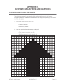
APPENDIX C:
Custom Characters and Graphics
APPENDIX D:
Optional Features
APPENDIX E:
Custom Protocol Command Codes
Appendix F:
Care Symbol Fonts
9001038 Rev. D
SATO XL Series Printers
Preface
TABLE OF CONTENTS
SECTION 1. PRINTER OVERVIEW
Introduction . . . . . . . . .
General Printer Specifications
Character Fonts . . . . . . . .
Bar Codes . . . . . . . . . . .
Physical . . . . . . . . . . . .
Optional Accessories . . . . .
.
.
.
.
.
.
.
.
.
.
.
.
.
.
.
.
.
.
.
.
.
.
.
.
.
.
.
.
.
.
.
.
.
.
.
.
.
.
.
.
.
.
.
.
.
.
.
.
.
.
.
.
.
.
.
.
.
.
.
.
.
.
.
.
.
.
.
.
.
.
.
.
.
.
.
.
.
.
.
.
.
.
.
.
.
.
.
.
.
.
.
.
.
.
.
.
.
.
.
.
.
.
.
.
.
.
.
.
.
.
.
.
.
.
.
.
.
.
.
.
1-1
1-2
1-4
1-5
1-6
1-7
Introduction . . . . . . . . . . .
Unpacking and Parts Identification
Setting Up the Printer . . . . . .
Printer Components . . . . . . .
Operator Panel . . . . . . . . . .
Media . . . . . . . . . . . . . .
Loading Tags and Labels . . . . .
Loading Ribbon . . . . . . . . . .
Cut Sensor Adjustment . . . . . .
Powering On/Off . . . . . . . . .
.
.
.
.
.
.
.
.
.
.
.
.
.
.
.
.
.
.
.
.
.
.
.
.
.
.
.
.
.
.
.
.
.
.
.
.
.
.
.
.
.
.
.
.
.
.
.
.
.
.
.
.
.
.
.
.
.
.
.
.
.
.
.
.
.
.
.
.
.
.
.
.
.
.
.
.
.
.
.
.
.
.
.
.
.
.
.
.
.
.
.
.
.
.
.
.
.
.
.
.
.
.
.
.
.
.
.
.
.
.
.
.
.
.
.
.
.
.
.
.
.
.
.
.
.
.
.
.
.
.
.
.
.
.
.
.
.
.
.
.
.
.
.
.
.
.
.
.
.
.
.
.
.
.
.
.
.
.
.
.
.
.
.
.
.
.
.
.
.
.
.
.
.
.
.
.
.
.
.
.
2-1
2-2
2-3
2-4
2-6
2-8
2-12
2-15
2-18
2-21
.
.
.
.
.
.
.
.
.
.
.
.
.
.
.
.
.
.
.
.
.
.
.
.
.
.
.
.
.
.
.
.
.
.
.
.
.
.
.
.
.
.
.
.
.
.
.
.
.
.
.
.
.
.
.
.
.
.
.
.
.
.
.
.
.
.
.
.
.
.
.
.
.
.
.
.
.
.
.
.
.
.
.
.
.
.
.
.
.
.
.
.
.
.
.
.
.
.
.
.
.
.
.
.
.
.
.
.
.
.
.
.
.
.
.
.
.
.
.
.
.
.
.
.
.
.
.
.
.
.
.
.
.
.
.
.
.
.
.
.
.
.
.
.
.
.
.
.
.
.
.
.
.
.
.
.
.
.
.
.
.
.
3-1
3-2
3-6
3-6
3-8
3-11
3-17
3-18
3-19
SECTION 2. INSTALLATION
SECTION 3. CONFIGURATION
Introduction . . . . . . . . . .
Printer DIP Switch Configuration
Printer Adjustments . . . . . . .
Normal Mode . . . . . . . .
User Mode . . . . . . . . .
Service Mode . . . . . . . .
User Test Print . . . . . . .
Service Test Print . . . . . .
Potentiometer Adjustments . . .
.
.
.
.
.
.
.
.
.
SECTION 4. CLEANING AND MAINTENANCE
Introduction . . . . . . . . . . . . . . . . . . . . . . . . . . . . .
Procedures . . . . . . . . . . . . . . . . . . . . . . . . . . . . . .
SATO XL Series Printers
9001038 Rev. D
4-1
4-1
Page - iii
Preface
Adjusting the Print Quality . . . . . . . . . . . . .
Darkness . . . . . . . . . . . . . . . . . . . .
Print Speed . . . . . . . . . . . . . . . . . . .
Cleaning the Print Head, Platen, Rollers and Sensors
.
.
.
.
.
.
.
.
.
.
.
.
.
.
.
.
.
.
.
.
.
.
.
.
.
.
.
.
4-1
4-1
4-2
4-3
.
.
.
.
.
.
.
.
.
.
.
.
.
.
.
.
.
.
.
.
.
.
.
.
.
.
.
.
.
.
.
.
.
.
.
.
.
.
.
.
.
.
.
.
.
.
.
.
.
.
.
.
.
.
.
.
.
.
.
.
.
.
.
.
.
.
.
.
.
.
.
.
.
.
.
.
.
.
.
.
.
.
.
.
.
.
.
.
.
.
.
.
.
.
.
.
.
.
.
.
.
.
.
.
.
.
.
.
.
.
.
.
.
.
.
.
.
.
.
.
.
.
.
.
.
.
.
.
.
.
.
.
.
.
.
.
.
.
.
.
.
.
.
.
.
.
.
.
.
.
.
.
.
.
.
.
.
.
.
.
.
.
.
.
.
.
.
.
.
.
.
.
.
.
.
.
.
.
.
.
.
.
.
.
.
.
.
.
.
.
.
.
.
.
.
.
.
.
.
.
.
.
.
.
.
.
.
.
.
.
.
.
.
.
.
.
.
.
.
.
.
.
.
.
.
.
.
.
.
.
.
.
.
.
.
.
.
.
.
.
.
.
.
.
.
.
.
.
.
.
.
.
.
.
.
.
.
.
.
.
.
.
.
.
.
.
.
.
.
.
.
.
.
.
.
.
.
.
.
.
.
.
.
.
.
.
.
.
.
.
.
.
.
.
.
.
.
.
.
.
.
5-1
5-1
5-2
5-2
5-4
5-8
5-9
5-10
5-11
5-13
5-14
5-16
5-17
5-19
5-21
5-23
5-25
5-26
5-28
5-30
5-32
5-34
5-35
5-36
5-37
5-38
5-40
5-41
5-42
5-44
5-46
5-47
5-48
5-49
5-50
5-52
5-53
5-54
5-55
5-57
5-59
5-61
5-63
SECTION 5. PROGRAMMING
Introduction . . . . . . . . . . . . .
The SATO XL Programming Language
Selecting Protocol Control Codes . . .
Using Basic . . . . . . . . . . . . . .
The Print Area . . . . . . . . . . . .
Rotated Fields . . . . . . . . . . . .
Command Default Settings . . . . . .
Command Codes . . . . . . . . . . .
Bar Codes . . . . . . . . . . . . .
Bar Codes, Expansion . . . . . . .
Bar Codes, Variable Ratio . . . . .
Batch Separator . . . . . . . . . .
Base Reference Point . . . . . . .
Characters, Custom Designed . . .
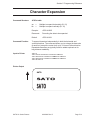
Character Expansion . . . . . . .
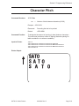
Character Pitch . . . . . . . . . .
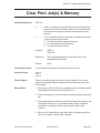
Clear Print Job(s) and Memory . .
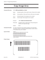
Copy Image Area . . . . . . . . .
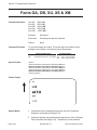
Fonts OA, OB, XU, XS and XM . .
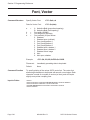
Font, Vector . . . . . . . . . . .
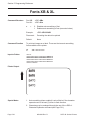
Fonts, XB and XL . . . . . . . . .
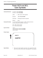
Fonts, XCS and XCL Care Symbol .
Form Feed . . . . . . . . . . . .
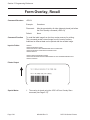
Form Overlay Recall . . . . . . .
Form Overlay Store . . . . . . . .
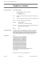
Graphics, Custom . . . . . . . . .
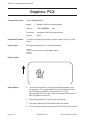
Graphics, PCX . . . . . . . . . .
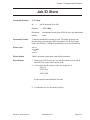
Job ID Store . . . . . . . . . . .
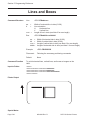
Lines and Boxes . . . . . . . . . .
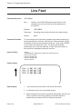
Line Feed . . . . . . . . . . . . .
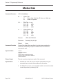
Media Size . . . . . . . . . . . .
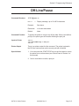
Off-Line/Pause . . . . . . . . . .
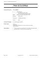
Print & Cut Offset . . . . . . . . .
Print Darkness . . . . . . . . . .
Print Position . . . . . . . . . . .
Print Quantity . . . . . . . . . .
Print Speed . . . . . . . . . . . .
Repeat Label . . . . . . . . . . .
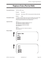
Replace Data (Partial Edit) . . . .
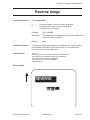
Reverse Image . . . . . . . . . .
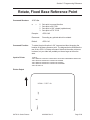
Rotate, Fixed Base Reference Point
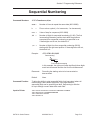
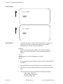
Sequential Numbering . . . . . .
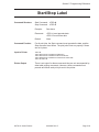
Start/Stop Label . . . . . . . . .
Page - iv
9001038 Rev. D
.
.
.
.
.
.
.
.
.
.
.
.
.
.
.
.
.
.
.
.
.
.
.
.
.
.
.
.
.
.
.
.
.
.
.
.
.
.
.
.
.
.
.
.
.
.
.
.
.
.
.
.
.
.
.
.
.
.
.
.
.
.
.
.
.
.
.
.
.
.
.
.
.
.
.
.
.
.
.
.
.
.
.
.
.
.
.
.
.
.
.
.
.
.
.
.
.
.
.
.
.
.
.
.
.
.
.
.
.
.
.
.
.
.
.
.
.
.
.
.
.
.
.
.
.
.
.
.
.
.
.
.
.
.
.
.
.
.
.
.
.
.
.
.
.
.
.
.
.
.
.
.
.
.
.
.
.
.
.
.
.
.
.
.
.
.
.
.
.
.
.
.
.
.
.
.
.
.
.
.
.
.
.
.
.
.
.
.
.
.
.
.
.
.
.
.
.
.
.
.
.
.
.
.
.
.
.
.
.
.
.
.
.
.
.
.
.
.
.
.
.
.
.
.
.
.
.
.
.
.
.
.
.
.
.
.
.
.
.
.
.
.
.
.
.
.
.
.
.
.
.
.
.
.
.
.
.
.
.
.
.
.
.
.
.
.
.
.
.
.
.
.
.
.
.
.
.
.
.
.
.
.
.
.
.
.
.
.
.
.
.
.
.
.
.
.
.
.
.
.
.
.
.
.
.
.
.
.
.
.
.
.
.
.
.
.
.
.
.
.
.
.
.
.
.
.
.
.
.
.
.
.
.
.
.
.
.
.
.
.
.
.
.
.
.
.
.
.
.
.
.
.
.
.
.
.
.
.
.
.
.
.
.
.
.
.
.
.
.
.
.
.
.
.
.
.
.
.
.
.
.
.
.
.
.
.
.
SATO XL Series Printers
Preface
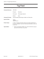
Tag Feed . . . . . . . . . . . . . . .
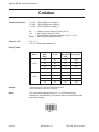
Calendar Option Commands . . . . .
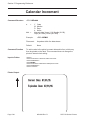
Calendar Increment . . . . . . . .
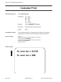
Calendar Print . . . . . . . . . .
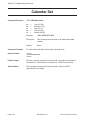
Calendar Set . . . . . . . . . . .
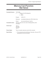
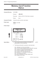
Memory Card Option Commands . . .
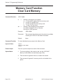
Clear Card Memory . . . . . . . .
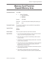
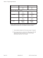
Expand Memory Area . . . . . . .
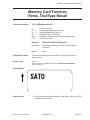
Fonts, TrueType Recall . . . . . .
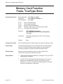
Fonts, TrueType Store . . . . . .
Format/Field Recall . . . . . . . .
Format/Field Store . . . . . . . .
Graphics, Custom Recall . . . . .
Graphics, Custom Store . . . . . .
Graphics, PCX Recall . . . . . . .
Graphics, PCX Store . . . . . . . .
Initialize . . . . . . . . . . . . .
Slot Select . . . . . . . . . . . .
Status . . . . . . . . . . . . . . .
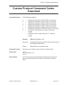
Custom Protocol Codes Download . .
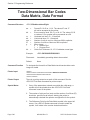
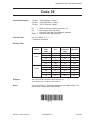
Two-Dimensional Symbols . . . . . .
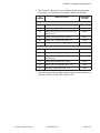
Data Matrix, Data Format . . . . .
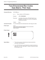
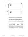
Data Matrix, Data Print . . . . . .
Data Matrix Sequential Numbering
Maxicode . . . . . . . . . . . . .
PDF417 . . . . . . . . . . . . . .
.
.
.
.
.
.
.
.
.
.
.
.
.
.
.
.
.
.
.
.
.
.
.
.
.
.
.
.
.
.
.
.
.
.
.
.
.
.
.
.
.
.
.
.
.
.
.
.
.
.
.
.
.
.
.
.
.
.
.
.
.
.
.
.
.
.
.
.
.
.
.
.
.
.
.
.
.
.
.
.
.
.
.
.
.
.
.
.
.
.
.
.
.
.
.
.
.
.
.
.
.
.
.
.
.
.
.
.
.
.
.
.
.
.
.
.
.
.
.
.
.
.
.
.
.
.
.
.
.
.
.
.
.
.
.
.
.
.
.
.
.
.
.
.
.
.
.
.
.
.
.
.
.
.
.
.
.
.
.
.
.
.
.
.
.
.
.
.
.
.
.
.
.
.
.
.
.
.
.
.
.
.
.
.
.
.
.
.
.
.
.
.
.
.
.
.
.
.
.
.
.
.
.
.
.
.
.
.
.
.
.
.
.
.
.
.
.
.
.
.
.
.
.
.
.
.
.
.
.
.
.
.
.
.
.
.
.
.
.
.
.
.
.
.
.
.
.
.
.
.
.
.
.
.
.
.
.
.
.
.
.
.
.
.
.
.
.
.
.
.
.
.
.
.
.
.
.
.
.
.
.
.
.
.
.
.
.
.
.
.
.
.
.
.
.
.
.
.
.
.
.
.
.
.
.
.
.
.
.
.
.
.
.
.
.
.
.
.
.
.
.
.
.
.
.
.
.
.
.
.
.
.
.
.
.
.
.
.
.
.
.
.
.
.
.
.
.
.
.
.
.
.
.
.
.
.
.
.
.
.
.
.
.
.
5-64
5-65
5-66
5-68
5-70
5-71
5-72
5-73
5-75
5-76
5-77
5-78
5-79
5-80
5-82
5-83
5-84
5-85
5-86
5-87
5-89
5-90
5-92
5-93
5-95
5-97
.
.
.
.
.
.
.
.
.
.
.
.
.
.
.
.
.
.
.
.
.
.
.
.
.
.
.
.
.
.
.
.
.
.
.
.
.
.
.
.
.
.
.
.
.
.
.
.
.
.
.
.
.
.
.
.
.
.
.
.
.
.
.
.
.
.
.
.
.
.
.
.
.
.
.
.
.
.
.
.
.
.
.
.
.
.
.
.
.
.
.
.
.
.
.
.
.
.
.
.
.
.
.
.
.
.
.
.
.
.
.
.
.
.
.
.
.
.
.
.
.
.
.
.
.
.
.
.
.
.
.
.
.
.
.
.
.
.
.
.
.
.
.
.
.
.
.
.
.
.
.
.
.
.
.
.
.
.
.
.
.
.
.
.
.
.
.
.
.
.
.
.
.
.
.
.
.
.
.
.
.
.
.
.
.
.
.
.
.
.
.
.
.
.
.
.
6-1
6-1
6-2
6-3
6-3
6-3
6-4
6-4
6-5
6-6
6-9
6-9
6-10
6-10
SECTION 6. INTERFACE SPECIFICATIONS
Introduction . . . . . . . . . . .
Interface Types . . . . . . . . . .
The Receive Buffer . . . . . . . .
RS232C Serial Interface . . . . .
General Specifications . . . .
Electrical Specifications . . . .
Pin Assignments . . . . . . .
Ready/Busy Flow Control . . .
X-On/X-Off Flow Control . . .
Bi-Directional Communications
Centronics Parallel Interface . . .
Electrical Specifications . . . .
Accessory (EXT) Connector . . . .
Pin Assignments . . . . . . .
SATO XL Series Printers
.
.
.
.
.
.
.
.
.
.
.
.
.
.
9001038 Rev. D
.
.
.
.
.
.
.
.
.
.
.
.
.
.
.
.
.
.
.
.
.
.
.
.
.
.
.
.
.
.
.
.
.
.
.
.
.
.
.
.
.
.
Page - v
Preface
SECTION 6. TROUBLESHOOTING
Initial Checklist . . . . . . . . . . . . .
Using the Centronics (Parallel) Interface
Using the RS232C (Serial) Interface . .
Error Signals . . . . . . . . . . . . . .
.
.
.
.
.
.
.
.
.
.
.
.
.
.
.
.
.
.
.
.
.
.
.
.
.
.
.
.
.
.
.
.
.
.
.
.
.
.
.
.
.
.
.
.
.
.
.
.
.
.
.
.
.
.
.
.
.
.
.
.
7-1
7-1
7-3
7-4
.
.
.
.
.
.
.
.
.
.
.
.
.
.
.
.
.
.
.
.
.
.
.
.
.
.
.
.
.
.
.
.
.
.
.
.
.
.
.
.
.
.
.
.
.
.
.
.
.
.
.
.
.
.
.
.
.
.
.
.
.
.
.
.
.
.
.
.
.
.
.
.
.
.
.
.
.
.
.
.
.
.
.
.
.
.
.
.
.
.
.
.
.
.
.
.
.
.
.
.
.
.
.
.
.
.
.
.
.
.
.
.
.
.
.
.
.
.
.
.
.
.
.
.
.
.
.
.
.
.
.
.
.
.
.
.
.
.
.
.
.
.
.
.
.
.
.
.
.
.
.
.
.
.
.
.
.
.
.
.
.
.
.
.
.
.
.
.
B-1
B-2
B-3
B-4
B-5
B-8
B-7
B-9
B-10
B-11
B-13
B-15
B-16
B-17
APPENDICES
APPENDIX A: Command Code Quick Reference
APPENDIX B: Bar Code Specifications
Bar Code Symbologies . . . . . . . . .
Codabar . . . . . . . . . . . . . . .
Code 39 . . . . . . . . . . . . . . .
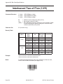
Interleaved Two of Five (I 2/5) . . .
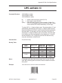
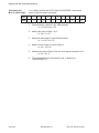
UPC-A/EAN-13 . . . . . . . . . . .
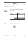
EAN-8 . . . . . . . . . . . . . . . .
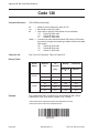
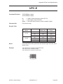
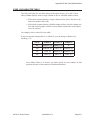
Code 128 . . . . . . . . . . . . . .
UPC-E . . . . . . . . . . . . . . . .
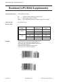
Bookland (UPC/EAN Supplements)
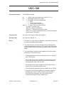
UCC-128 . . . . . . . . . . . . . .
Data Matrix . . . . . . . . . . . . .
Maxicode . . . . . . . . . . . . . .
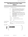
PDF417 . . . . . . . . . . . . . . .
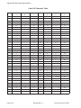
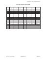
Code 128 Character Table . . . . .
Page - vi
.
.
.
.
.
.
.
.
.
.
.
.
.
.
APPENDIX C: Custom Characters and Graphics
Custom Designed Characters Example . . . . . . . . . . . . . .
Custom Graphics Example . . . . . . . . . . . . . . . . . . . .
PCX Graphics Example . . . . . . . . . . . . . . . . . . . . . .
C-1
C-4
C-8
APPENDIX D: Optional Accessories
Label Rewinder . . . . . . . .
PCMCIA Memory Cards . . . .
Stacker . . . . . . . . . . . .
Calendar . . . . . . . . . . .
.
.
.
.
.
.
.
.
.
.
.
.
.
.
.
.
.
.
.
.
.
.
.
.
.
.
.
.
.
.
.
.
.
.
.
.
.
.
.
.
.
.
.
.
.
.
.
.
.
.
.
.
D-1
D-2
D-4
D-6
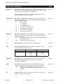
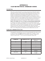
APPENDIX E: Custom Protocol Command Codes
Description . . . . . . . . . . . . . . . . .
Download Command Structure . . . . . . .
Download Procedure . . . . . . . . . . . .
Reset . . . . . . . . . . . . . . . . . . . .
.
.
.
.
.
.
.
.
.
.
.
.
.
.
.
.
.
.
.
.
.
.
.
.
.
.
.
.
.
.
.
.
.
.
.
.
.
.
.
.
.
.
.
.
E-1
E-1
E-2
E-2
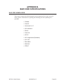
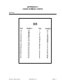
Appendix F: Care Symbol Fonts
XCS Font . . . . . . . . . . . . . . . . . . . . . . . . . . . . .
XCM Font . . . . . . . . . . . . . . . . . . . . . . . . . . . . .
F-1
F-2
9001038 Rev. D
.
.
.
.
.
.
.
.
.
.
.
.
.
.
.
.
.
.
.
.
SATO XL Series Printers
SECTION 1.
PRINTER OVERVIEW
INTRODUCTION
The SATO XL400 and XL410 Thermal Transfer Printers are complete,
high-performance labeling systems designed specifically for printing tags and labels.
All printer parameters are programmable using the front panel controls and DIP
switches. All popular bar codes, including 2-D codes, eight human-readable fonts
with two Care Symbol fonts and a fast and efficient vector font, are resident in
memory, providing literally thousands of type styles and sizes.
The Operator’s Manual will help you understand the basic operations of the printer,
such as setup, installation, configuration, cleaning and maintenance.
The major difference in the XL400 and the XL410 is the resolution of the head. The
XL400 with its 203 dpi head provides an economical labeling solution for most
applications. The XL410 provides a higher print resolution, 305 dpi, to give
laser-quality printing. It is useful when high-resolution printing is required, such as
when printing detailed graphic images. Both printers can print labels up to 4.0 inches
wide and 9.4 inches long using internal memory. If longer labels are required, a
PCMCIA memory card option is available, allowing 203 dpi labels up to 49.2 inches
(32.8 inches for 305 dpi).
All of the XL printers use the same command codes. The only differences are the
allowable values representing print positions on the label. These values are specified
in “dots” and will vary depending upon the resolution of the printer and the amount
of memory available for imaging the label. The allowable range for each printer is
specified in a table for those commands.
The standard configuration for the XL printers includes an integrated Cutter which
can operate at the maximum print speed. A Stacker is available as an option and can
stack up to 500 labels up to 3.9 inches wide and 5.9 inches long at maximum print
speeds.
The following general information is presented in this section:
• General Printer Specifications
• Optional Accessories
SATO XL Series Printers
9001038 Rev. D
Page 1- 1
Section 1. Printer Overview
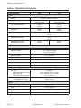
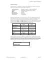
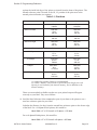
GENERAL PRINTER SPECIFICATIONS
SPECIFICATION
XL400
XL410
PRINT
Method
Direct or Thermal Transfer
Speed (User Selectable)
5 to 8 ips
125 to 200 mm/s
4 to 6 ips
100 to 150 mm/s
Print Module (Dot Size)
.0049 in.
.125 mm
.0033 in.
.083 mm
Resolution
203 dpi
8 dpmm
305 dpi
12 dpmm
Maximum Print Width
3.94 in.
100 mm
Maximum Print Length
9.45 in.
240 mm
Maximum Print Length
with 2MB Memory Card
49.2 in.
1249 mm
32.8 in.
833 mm
MEDIA
Minimum Width
1.26 in. (32 mm)
Minimum Length
.75 in. (19 mm) Labels
1.0 in. (25 mm) Tags
Maximum Width
4.0 in. (102 mm)
Type
Die Cut Labels, Fan-Fold, Tag Stock or Continuous
Caliper (max)
.012 in. (.3 mm)
Roll OD (max)
9.8 in. (249 mm)
Core ID (min)
4.0 in. (102 mm)
SENSING
See-Thru
Label Gap/Center Hole Tag
Side Hole Tag
Side Notch (R-Corner Tag)
Adjustable
0.4 in. (16mm0 to 2.0 in. (50mm)
1.3 in. (34mm) to 3.7 in. (94mm)
0.1 in. (2.5mm)
Reflective Eye-Mark
Eye-Mark Label or Tag
Fixed
0.28 in. (7 mm)
RIBBON
Maximum Width
4.0 in. (102 mm)
Length
1475 ft. (450 M)
Wind
Ink-In
Thickness
Page 1- 2
4.5 micron
9001038 Rev. D
SATO XL Series Printers
Section 1. Printer Overview
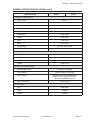
GENERAL PRINTER SPECIFICATIONS (cont’d)
SPECIFICATION
XL400
XL410
CONTROLS AND SIGNALS
On-Line LED
Green
Cutter
Green
Error LED
Red
LCD Panel
2 Line x 16 Character
Start/Stop Switch
Rear
Feed Switch
Front Panel
Cutter
Front Panel
Eject
Front Panel
Media
Front Panel
Configuration
3 x 8 DIP, Inside Cover
Power On/Off Switch
Rear Panel
POTENTIOMETER ADJUSTMENTS
Print Darkness
Inside Cover
Pitch
Inside Cover
Offset
Inside Cover
Display
Inside Cover
INTERFACE CONNECTIONS
Parallel (AMP 36 pin)
Centronics Compatible
Serial (DB25S)
RS232C (2400 to 19.2K bps)
Serial Protocol
Hardware Flow Control (Ready/Busy)
Software Flow Control (X-On/X-Off)
Bi-directional (ENQ/Response)
Data Transmission
ASCII Format
PROCESSING
CPU
32 Bit RISC
ROM
1 MByte
DRAM
2 MByte
SATO XL Series Printers
9001038 Rev. D
Page 1- 3
Section 1. Printer Overview
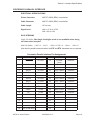
CHARACTER FONTS
SPECIFICATION
XL400
XL410
MATRIX FONTS
XU Font
(5 dots W x 9 dots H) Helvetica
XS Font
(17 dots W x 17 dots H) Univers Condensed Bold
XM Font
(24 dots W x 24 dots H) Univers Condensed Bold
OA Font
(15 dots W x 22 dots H)
OCR-A
(22 dots W x 33 dots H)
OCR A
OB Font
20 dots W x 24 dots H)
OCR-B
(30 dots W x 36 dots H)
OCR B
XCS
(24 dot W x 24 dot H) Care Symbol
XCL
(36 dots W x 36 dots H) Care symbol
AUTO SMOOTHING FONTS
XB
XB Font (48 dots W x 48 dots H) Univers
Condensed Bold
XL
XL Font (48 dot W x 48 dots H) Sans Serif
VECTOR FONT
Proportional or Fixed Spacing
Font Size 50 x 50 dots to 999 x 999 dots
10 Font Variations
DOWNLOADABLE FONTS
TrueType Fonts with Optional Memory Card
CHARACTER CONTROL
Expansion up to 12X in either the X or Y
coordinates
Character Pitch control
Line Space control
Journal Print facility
0°, 90°, 180° and 270° Rotation
Page 1- 4
9001038 Rev. D
SATO XL Series Printers
Section 1. Printer Overview
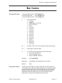
Bar Codes
SPECIFICATION
XL400
XL410
SYMBOLOGIES
Bookland (UPC/EAN Supplemental)
EAN-8, EAN-13
CODABAR
Code 39
Code 128
Interleaved 2 of 5
UCC/EAN-128
UPC-A and UPC-E
Data Matrix
Maxicode
PDF417
Ratios
Bar Height
1:2, 1:3, 2:5 User definable bar widths
4 to 600 dots, User programmable
Rotation
0°, 90°, 180° and 270°
OTHER FEATURES
Sequential Numbering
Custom Characters
Sequential numbering of both numerics and bar codes
RAM storage for special characters
Graphics
Full dot addressable graphics, SATO Hex/Binary or PCX
formats
Form Overlay
Form overlay for high-speed editing of complex formats
SATO XL Series Printers
9001038 Rev. D
Page 1- 5
Section 1. Printer Overview
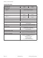
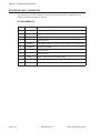
PHYSICAL
SPECIFICATION
XL400
XL410
DIMENSIONS
Wide
19.6 in. (302 mm)
Deep
11.8 in. (552 mm)
High
11.5 in. (294 mm)
WEIGHT
30.8 lbs (14 Kg)
POWER REQUIREMENTS
Voltage
100 - 115 V (±10 %)
220V (±10 %)
50/60 Hz (±1%)
Power Consumption
300 Watts Operating
ENVIRONMENTAL
Operating Temperature
Storage Temperature
41° to 104°F (5° to 40°C
-0° to 104°F (-20° to 40°C)
Operating Humidity
15-85 % RH, non-condensing
Storage Humidity
Max 90% RH, non-condensing
Electrostatic Discharge
8KV
REGULATORY APPROVALS
Safety
UL, CSA, CE
RFI/EMI
FCC Class A
Page 1- 6
9001038 Rev. D
SATO XL Series Printers
Section 1. Printer Overview
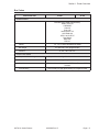
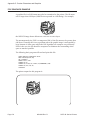
OPTIONAL ACCESSORIES
ACCESSORY
XL400
XL412
MEMORY EXPANSION
Two slots for PCMCIA Memory Cards (up to 2MB each). Can be used
for graphic file storage, print buffer expansion and downloaded
TrueType fonts.
CALENDAR
An internally mounted Date/Time clock that can be used to date/time
stamp labels at the time of printing.
INTEGRATED STACKER
Allows cut labels to be stacked. Interfaces to EXT Accessory Port
connector.
LABEL REWINDER
External option rewinds labels onto a roll after they are printed.
SATO XL Series Printers
9001038 Rev. D
Page 1- 7
Section 1. Printer Overview
This page left intentionally blank.
Page 1- 8
9001038 Rev. D
SATO XL Series Printers
SECTION 2.
INSTALLATION
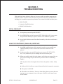
INTRODUCTION
This section is provided to assist you in taking the XL printer from the shipping
container and familiarization with the controls.
The following information is provided in this section:
• Unpacking and Parts Identification
• Setting Up the Printer
• Loading Labels or Tags
• Loading the Ribbon
• Adjusting the Sensors
• Powering On/Off
SATO XL Series Printers
9001038 Rev. D
Page 2-1
Section 2. Installation
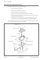
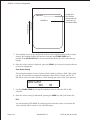
UNPACKING AND PARTS IDENTIFICATION
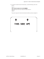
Consider the following when unpacking the printer:
• The box should stay right-side up.
• Lift the printer out of the box carefully.
• Remove the plastic covering from the printer.
• Remove the accessory items from their protective containers.
• If the printer has been stored in a cold environment, allow it to reach room
temperature before powering it on.
• Set the printer on a solid, flat surface. Inspect the shipping container and
printer for any sign of damage that may have occured during shipping.
Note: The following illustrations are representative only. Your printer may not be packed
exactly as shown, but the unpacking steps are similar.
Cardboard Cover
Top Foam Inserts
XL Printer
Plastic Protective
Bottom Foam Inserts
Accessory Box
Shipping Container
Page 2-2
9001038 Rev. D
SATO XL Series Printers
Section 2. Installation
Verify that you have the following materials when unpackaging:
• Printer
• Power Cord
• Extra Ribbon Core
• Operator’s Manual
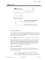
SETTING UP THE PRINTER
Consider the following when setting up the printer:
• Locate a solid, flat surface with adequate room to set the printer. If a
Cutter/Stacker is to be used with the printer, make sure thaere is adequate
room for the unit. The printer cover swings upward and back, make sure
there is enough clearance for the cover to swing open.
• The location should be near the host computer or terminal. The maximum
distance for RS232 cables is 50 feet and six feet for Centronics parallel
cables. Cables can be purchased locally and their configuration will depend
upon the host system.
• For information on interfacing the printer to a host system, see Section 6:
Interface Specifications.
The procedures for setting up the printer and adjusting the sensors are outlined in
Section 2. The procedures for setting ut the operating parameters (Print Speed, Pitch
Offset, etc.)are outlined in Section 3.
• Load the ribbon (see page 2-15).
• Load the Media (see page 2-12).
• Setup the printer for the media type (see page 2-8). You must use the LCD
panel to select the proper media type (see page 2-14). The selections are:
Center Hole Tag
I-Mark Tag
Side Hole Tag
R-Corner Tag
Label Gap
I-Mark Label
• Adjust the Cutter Sensor (see page 2-18). Note: The Cutter Sensor must be
set up even if the Cutter is disabled.
• Adjust the Cutter Offset to corectly locate the cut position. This can
generally be done with the Cut Position potentiometer on the Control Panel
(see page 3-20) which has a +/- 3.75mm range. If this is insufficient, the
Cut Offset can be moved +/- 99 dots using the LCD panel (see page 3-15).
• Set the Pitch, Cut and Backfeed Offset using the LCD panel (see page 3-14).
SATO XL Series Printers
9001038 Rev. D
Page 2-3
Section 2. Installation
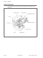
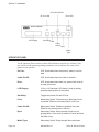
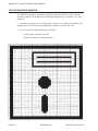
PRINTER COMPONENTS
Before attempting to set up the printer, please familiarize yourself with the major
components.
Ribbon Rewind
Ribbon Unwind
Media Supply Spindle
Cover
Media Retaining Plate
Print Head
Head Lock Lever
Cutter
Page 2-4
Operator Panel
9001038 Rev. D
SATO XL Series Printers
Section 2. Installation
DIP Switch and
Potentiometer Cover
Fuse
Power Switch
Media Hold-Down
AC Connector
Power Switch
INTERFACE
CONNECTORS
Centronics Parallel
Serial RS232
EXT Accessory
SATO XL Series Printers
9001038 Rev. D
Page 2-5
Section 2. Installation
Cutter On/Off LED
Error LED
On Line LED
SATO XL PRINTER
LCD Display
Start/Stop
Feed
Cutter
On/Off
Eject
Media
Type
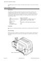
OPERATOR PANEL
The XL Operator Panel consists of three LED indicators and five key switches. They
are used to set the printer operating parameters and to indicate the status of the
printer to the operator.
Page 2-6
On Line:
LED. Illuminated when the printer is ready to receive
data.
Cutter On/Off:
LED. Illuminated when the Cutter is enabled.
Error:
LED. Illuminated when there is a system fault such as
an open print head.
LCD Display:
2 Line x 16 Character LCD display. Used for setting
operational parameters of the printer.
Start/Stop:
Toggles the printer On and Off Line.
Feed:
Momentary Switch. Feed one tag or label each time it
is pressed. Effective only when printer is Off Line.
Cutter On/Off:
Momentary Switch. Enables or disables the cutter.
Effective only when printer is Off Line.
Eject:
Momentary Switch. When pressed, feeds out any
printed labels. If the cutter is enabled, it feeds and cuts
the label or tag.
Media Type:
Momentary Switch. Steps through the media types.
9001038 Rev. D
SATO XL Series Printers
Section 2. Installation
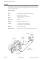
Operator Panel
Push in for Tilt
position
The Operator Panel has two positions; one is flush with the printer (vertical) and the
other is tilted backward. The position should be set for the best viewing by the
operator.
Release for Vertical
position
Operator Panel
SATO XL Series Printers
9001038 Rev. D
Page 2-7
Section 2. Installation
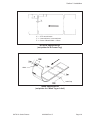
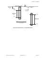
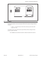
MEDIA
Tag Types
Tag Cut Line
Side Notch
Center-Hole Tag without Notch
(set printer for Center Hole)
Center-Hole Tag with Side Notch
(set printer for Center Hole)
Outside Edge
Outside Edge
Side-Hole Tag without Notch
(set printer for Side Hole)
Page 2-8
Side-Hole Tag with Side Notch
(set printer for Side Hole)
9001038 Rev. D
SATO XL Series Printers
Section 2. Installation
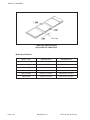
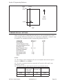
X: = 3.75 mm minimum
Y: = 2 mm minimum, 3 mm maximum
Z: = Center of Notch Width = 2.5mm
R-Corner Specifications
(set printer for R-Corner Tag)
I-Mark
Label Gap
I-Mark Specifications
(set printer for I-Mark Tag or Label)
SATO XL Series Printers
9001038 Rev. D
Page 2-9
Section 2. Installation
Label Gap
Label Gap Specifications
(set printer for Label Gap)
Media Specifications
Page 2-10
MEDIA TYPE
MINIMUM SIZE
MAXIMUM SIZE
Center Hole Tag
32mm W x 25 mm L
100mm W x 240mm L
I-Mark Tag
32mm W x 25mm L
100mm W x 240mm L
Side Hole Tag
50mm W x 25mm L
100mm W x 240mm L
R-Corner Tag
32mm W x 25mm L
100mm W x 240mm L
Label with Gap
25mm W x 16mm L
100mm W x 237mm L
I-Mark Label
32mm W x 25mm L
100mm W x 237mm L
9001038 Rev. D
SATO XL Series Printers
Section 2. Installation
INSIDE MEDIA GUIDE
R-Corner Sensor
2.5mm
I-Mark Sensor
7mm
16mm
Sensor
(not used)
Center Hole &
Gap Sensor
Range
34mm
50mm
Side Hole Tag
Sensor Range
Feed Direction
94mm
Sensor Positions Relative to Inside Media Guide
SATO XL Series Printers
9001038 Rev. D
Page 2-11
Section 2. Installation
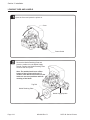
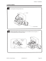
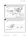
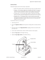
LOADING TAGS AND LABELS
Open the Cover and power the printer on.
Turn power on and open the cover.
Cover
Power Switch
Remove the Media Retaining Plate and
place the media roll on the Media Supply
Spindle.Remove
Replacethe
theMedia
MediaRetaining
RetainingPlate
Plateand load the tag roll.
to secure the roll in place.
Note: The media should come off the
bottom of the roll (wound face-in). If
media is used that is wound face-out, the
label curl can cause problems with the
stacking of the labels.
Tag Roll
Media Retaining Plate
Media Supply Spindle
Page 2-12
9001038 Rev. D
SATO XL Series Printers
Section 2. Installation
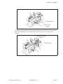
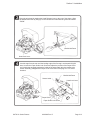
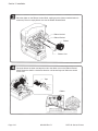
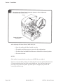
Open the print head by rotating the Head Release Lever to the rear of the printer. Open
the Media Hold Down by lifting up on the release tab underneath the green tab marked
“PUSH.”
Media Hold Down
Head Lock Lever
Load the tags from the rear until the leading edge of the first tag is underneath the print
head. Loosen the Paper Guide Lock Screw and adjust the position of the Paper Guide
until it holds the tag gently against the inside of the paper path (this also positions the
sensor assembly). Retighten the Paper Guide Lock Screw. See page 2-11 for sensor
locations.
Media Hold Down
Sensor Label
Head Lock Lever
Tag Setting
Position
Tag
Paper Guide
Paper Guide Lock Screw
SATO XL Series Printers
9001038 Rev. D
Page 2-13
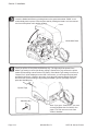
Section 2. Installation
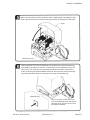
latch
theby
Media
Holddown
Downonand
close
Cover.
Close theClose
Mediaand
Hold
Down
pushing
thethen
green
tab the
marked
“PUSH.” It will
automatically latch in place. Close the print head by rotating the Head Lock Lever toward
the front of the printer until it latches in place.
Cover
Media Hold Down
Power the printer On and press the Start/Stop key. The tags should be ejected if the
Media Type setting is correct (the factory setting is Center-Hole Tag, however the printer
retains the last setting entered via the LCD Panel). If the Media Type setting is incorrect, a
“Sensor Error” will be displayed on the LCD. If this occurs, you must open the print head
and Media Hold Down, reposition the media, close the print head and Media Hold Down
and select the correct media type by pressing the Media Type key (see page 2-8) and
press the Start/Stop key.
Ejected Tags
Start/Stop Key
Note:
If you
get a “Cutter
Error,”
you
must if
Refer
to Ribbon
Loading
in this
section
correctly
podsition
the
Cut
Sensor.
See
there is no ribbon in the printer.
page 2-19. This can occur even if the
Cutter is disabled.
Page 2-14
9001038 Rev. D
SATO XL Series Printers
Section 2. Installation
LOADING RIBBON
Turn the power off and open the Cover.
Cover
Power Switch
Open the print head by rotating the Head Lock Lever toward the rear of the printer. It
will automatically retract to the open position.
Head Lock
Lever
SATO XL Series Printers
9001038 Rev. D
Page 2-15
Section 2. Installation
Place the ribbon on the Ribbon Unwind Shaft, making sure the ribbon unwind direction is
as shown). Place an empty ribbon core one the Ribbon Rewind Shaft.
Ribbon Unwind
Ribbon Rewind
Ribbon
Ribbon Core
Route the ribbon as shown and tape the end to the ribbon core on the Ribbon Rewind
Shaft. Rotate the shaft in a clockwise direction until several layers of ribbon are wound
on the core.
Tape
Ribbon
Page 2-16
9001038 Rev. D
SATO XL Series Printers
Section 2. Installation
Make sure the media is fed into the printer with the leading edge underneath the print
head. Close and latch the print head in the down position by rotating the Head Latch.
Cover
Head Lock Lever
Power the printer On. Press the Start/Stop key to initiate the automatic media feed.
If the Media Type setting is incorrect, a “Sensor Error” will be displayed on the LCD.
If this occurs, you must open the print head and Media Hold Down, reposition the
media, close the print head and Media Hold Down and select the correct media type
by pressing the Media Type key (see page 2-8). Press the Start/Stop key.
Start/Stop Key
Note: If you get a “Cutter Error,” you
must correctly position the Cut Sensor.
See page 3-20. This can occur even if
the Cutter is disabled.
SATO XL Series Printers
9001038 Rev. D
Page 2-17
Section 2. Installation
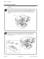
CUT SENSOR ADJUSTMENT
These adjustments are for R-Corner Tag (Side-Notch), Center-Hole and Edge-Hole
tags only.
Open the cover. The Cut Sensors are located on an adjustable assembly that must be
correctly positioned for the type of media used. They must be adjusted correctly even
though the Cutter is disabled. If they are not, a “Cutter Error” will result when you try to
feed tags.
Cover
Loosen the green Sensor Adjustment Thumbscrew on the Cutter Sensor assembly.
Align the notch on the Cutter Sensor Assembly to the position of the tag registration
mark using the scale.
Sensor
Adjustment
Thumbscrew
Page 2-18
Cutter
Sensor
Assembly
9001038 Rev. D
SATO XL Series Printers
Section 2. Installation
The scale used depends upon the type of media selected (i.e. R-Corner, Center-Hole or
Side-Hole) and the setting corresponds to the width of the media (i.e., if you are using
center hole tags that are 80mm wide, the notch should be set at the 80mm mark of the
black scale).
Notch
R-Corner: .
Center-Hole:
. . . . . . .
. . . . . . .
Side Hole: .
Scale
.
.
.
.
.
Inside scale, 32 to 42mm.
Black scale
Other Tag, 47 to 100mm
R-Corner, 32 to 42mm
Blue scale, 50 to 100mm
See Tag Charts on pages 2-8 to 2-9 if you
are unsure about tag type.
If you are using R-Corner Notch Tags, the tag notch must be on the inside edge of the
tag and the position the Sensor Select Switch should be towards the outside of the
printer. For all other tags, the Sensor Selector Switch should be towards the inside of
the printer.
R-Corner
Other Tag
See Tag Charts on pages 2-8 to 2-9 if you
are unsure about tag type.
SATO XL Series Printers
9001038 Rev. D
Page 2-19
Section 2. Installation
After adjusting the Cutter Sensor Assembly, tighten the Sensor Adjustment
Thumbscrew and close the Cover.
Cover
Sensor Adjustment
Thumbscrew
After adjusting the Cutter Sensor, make sure you:
• Have the media and ribbon loaded correctly.
• The media and ribbon type are correct for the configuration.
• The Print Head and Media Hold Down are latched in the closed position.
• The cover is closed.
NOTES:
If the media is not positioned correctly, press the FEED key to realign it.
If power is removed while printing, the media may be incorrectly positioned when power
is restored and the printer may print several blank tags. Press the Start/Stop key to
pause the print job and turn power off. When power is reapplied, the printer will
correctly position the tags.
Page 2-20
9001038 Rev. D
SATO XL Series Printers
Section 2. Installation
POWERING ON/OFF
SATO XL PRINTER
Total number of labels printed. Will increment
each time a label is printed since the last
time the printer was powered On.
Total number of labels to be printed. Will
decrement each time a label is printed.
Before Turning Power Off
When removing power from the printer, you should first feed any printed labels or
tags out of the printer by pressing the EJECT key while the printer is On Line. Any
tags printed but still in the printer will be fed out, cut and the tag/label retracted to
place the first print line under the head.
Note: The EJECT operation can be controlled via software commands from the host.
After the printed labels have been ejected from the printer, place the printer in the
OFF LINE state before removing power. If the label/tag position is not disturbed
while power is off, then the first printable label/tag will be in the correct position
when power is reapplied. The Media Type setting is retained in the printer even
though power is removed. When power is reapplied, the first print line of the
tag/label will be correctly positioned under the print head.
Replenishing the Tag Supply
When replenishing the tag/label supply with the same type and size, it is not
necessary to power the printer off. The printer will automatically position the new
media to the correct position.
• Raise the print head and relatch it to clear the “Paper End” Error.
• Unlatch the Media Hold Down and position the leading edge of the
media even with the mark on the “Tag Setting Position” label. If labels are
SATO XL Series Printers
9001038 Rev. D
Page 2-21
Section 2. Installation
being used, the leading edge of the first label should be under the print
head and even with the “Label Setting Position” label.
• Close the Media Hold Down and press the START/STOP key.
• The printer will automatically feed the media into the printer and position
it correctly.
Page 2-22
9001038 Rev. D
SATO XL Series Printers
SECTION 3.
CONFIGURATION
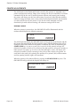
INTRODUCTION
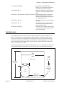
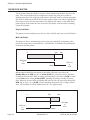
The configuration settings for the XL Series printers are set in two ways. The first is
via three DIP switches (DSW1, DSW2 and DSW3) located under the cover. The other
is using the Operator Panel LCD Display.
CONTROL PANEL
Control Panel Cover
Fuse
Label Hold Down
Power Switch
AC
Connector
Cutter On/Off LED
Error LED
On Line LED
SATO XL PRINTER
LCD Display
Start/Stop
Feed
Cutter
On/Off
Eject
Media
Type
SATO XL Series Printers
9001038 Rev. D
Page 3-1
Section 3. Printer Configuration
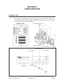
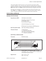
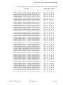
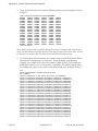
PRINTER DIP SWITCH CONFIGURATION
DIP Switch Panels
There are three DIP switches (DSW1, DSW2 and DSW3) located underneath an
access panel inside the printer. These switches can be used to set:
• RS232C transmit/receive parameters
• Thermal transfer or direct thermal mode
• Head check mode
• Hex dump mode
• Receive buffer size
• Operation mode
Each switch is an eight section “toggle” switch. The ON position is always to the top
(up). To set the switches, first power the unit Off, then position the DIP switches.
Finally, after placing the switches in the desired positions, power the printer back on.
The switch settings are read by the printer electronics during the power up sequence.
They will not become effective until the power is cycled.
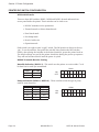
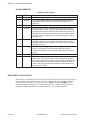
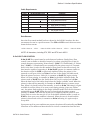
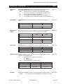
RS232 Transmit/Receive Setting
Data Bit Selection (DSW1-1) - This switch sets the printer to receive either 7 or 8
bit data bits for each byte transmitted.
DSW1
DSW1-1
SETTING
Off
8 data bits
On
7 data bits
ON
OFF
1
2
3
4
5
6
7
8
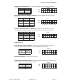
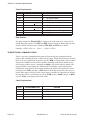
Parity Selection (DSW1-2, DSW1-3) - These switches select the type of parity
used for error detection.
Page 3-2
DSW1-2
DSW1-3
SETTING
Off
Off
No Parity
Off
On
Even
On
Off
Odd
On
On
Not Used
9001038 Rev. D
DSW1
ON
OFF
1
2
3
4
5
6
7
8
SATO XL Series Printers
Section 3. Printer Configuration
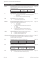
Stop Bit Selection (DSW1-4) - Selects the number of stop bits to end each byte
DSW1
transmission.
DSW1-4
SETTING
ON
Off
1 Stop Bit
OFF
On
2 Stop Bits
1
2
3
4
5
6
7
8
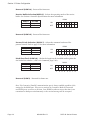
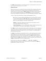
Baud Rate Selection (DSW1-5, DSW1-6) - Selects the data rate (bps) for the
RS232 port.
DSW1
DSW1-5
DSW1-6
SETTING
Off
Off
9600
ON
Off
On
19200
OFF
On
Off
4800
On
On
2400
1
2
3
4
5
6
7
8
Protocol Selection (DSW1-7, DSW1-8) - Selects the flow control and status
reporting protocols. See Section 6: Interface Specifications for more information.
DSW1
DSW1-7
DSW1-8
SETTING
Off
Off
Rdy/Bsy
ON
Off
On
X-On/X-Off
OFF
On
Off
Bi-Com
On
On
Not Used
1
2
3
4
5
6
7
8
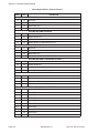
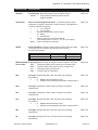
Printer Set Up
Print Mode Selection (DSW2-1) - Selects between direct thermal printing on
thermally sensitive paper and thermal transfer printing using a ribbon.
DSW2-1
SETTING
Off
Therm Xfr
On
Direct Therm
DSW2
ON
OFF
1
2
3
4
5
6
7
8
Reserved (DSW2-2) - Reserved for future use
Head Check Selection (DSW2-3) - When selected, the printer will check for head
elements that are electrically malfunctioning.
DSW2
DSW2-3
SETTING
ON
Off
Disabled
OFF
On
Enabled
SATO XL Series Printers
9001038 Rev. D
1
2
3
4
5
6
7
8
Page 3-3
Section 3. Printer Configuration
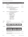
Reserved (DSW2-4) - Reserved for future use.
Receive Buffer Selection(DSW2-5) - Selects the operating mode of the receive
buffer. See Section 6: Interface Specifications for more information.
DSW2-5
SETTING
Off
Single Job
On
Multi Job
DSW2
ON
OFF
1
2
3
4
5
6
7
8
7
8
Reserved (DSW2-6) - Reserved for future use.
Protocol Code Selection (DSW2-7) - Selects the command codes used for
protocol control. Refer to page E-1for more information.
DSW2-7
SETTING
Off
Standard
On
Non-Std
DSW2
ON
OFF
1
2
3
4
5
6
Pitch Size Check (DSW2-8) - Checks the length on the installed media against the
size loaded via software (<ESC>A1 Command, page 5-46).
DSW2-8
SETTING
Off
Disabled
On
Enabled
DSW2
ON
OFF
1
2
3
4
5
6
7
8
Reserved (DSW3) - Reserved for future use.
Note: The Centronics (Parallel) communications port is always enabled regardless of the
settings for the RS232 port. There are no settings for Centronics! Both the Centronics
and RS232 ports are active at all times. Care should be taken to ensure that data is not
transmitted to both ports simultaneously as the received message will be corrupted.
Page 3-4
9001038 Rev. D
SATO XL Series Printers
Section 3. Printer Configuration
Default Settings
Switch Selections - All switches are placed in the Off position (default) for shipping.
This will result in the following operating configuration:
Communications
Protocol:
Mode:
Head Check:
Receive Buffer:
Pitch Check:
8 data bits, no parity, 1 Stop bit, 9600 Baud
Ready/Busy, Standard Protocol Codes
Thermal Transfer
Disabled
Single Job
Sensor Used
Software Default Settings - The printer stores the software settings upon receipt and
uses them until they are again changed by receipt of a command containing a new
setting. These settings are stored in non-volatile RAM and are not affected by
powering the printer off. The printer may be reset to use the default software settings
by depressing the FEED and START/STOP keys simultaneously while powering the
printer on. This will result in the following default configuration:
XL400
XL410
2
2
6 inches per second
5 inches per second
Print Reference
Vertical = 001
Horizontal = 001
Vertical = 001
Horizontal = 001
Media type
Center hole Tag
Center Hole Tag
Enabled
Enabled
Slash
Slash
Print Darkness
Print Speed
Cutter
Zero
Once the default operation is completed, a “SATO DEFAULT COMPLETED” message
will be displayed on the LCD panel or a single “beep” will be heard if the printer does
not have an LCD panel. The printer should be powered off while this message is being
displayed (or after the “beep” is heard. This saves the default settings in the EEPROM
where they will be automatically loaded the next time the printer is powered on.
SATO DEFAULT
COMPLETED
SATO XL Series Printers
9001038 Rev. D
Page 3-5
Section 3. Printer Configuration
PRINTER ADJUSTMENTS
The LCD Panel on the XL400 and XL410 is used by the operator to manually enter
printer configuration settings. Many of the settings can also be controlled via software
commands and in the case of conflict between software and control panel settings,
the printer will always use the last valid setting. If you load a label job that includes
software settings and then enter a new setting via the Operation Panel, the manually
set values will be used by the printer. If you set the values manually and then
download a job with software settings, the software settings will be used.
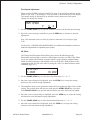
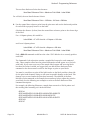
NORMAL MODE
When the printer is powered on, the ON-LINE LED will be illuminated and the
readout should display the following message:
ON LINE
000000
000000
The LCD Panel will display the ON LINE status on the top line of the display and the
the bottom line will contain the label quantity status. The ON LINE message will be
changed to OFF LINE whenever the printer is switched OFF LINE by depressing the
START/STOP key. As soon as a print job is received, the left quantity message will
indicate the number of labels to be printed and the right quantity message the number of
labels printed since power up. As soon as the label job begins to print, the display will
indicate the number of labels remaining in the print job that remain to be printed. As
each label in the print job is printed, the quantity to be printed (left) will decrement
and the quantity printed (right) will increment.
When the printer is first taken offline by pressing the START/STOP key once. The
ON LINE LED will go off and the display will change to:
CENTER HOLE TAG
000000
000000
Page 3-6
9001038 Rev. D
SATO XL Series Printers
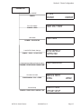
Section 3. Printer Configuration
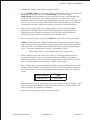
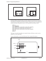
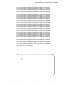
POWER ON
ON LINE
000000
Normal MODE
POWER
000000
USER TEST PRINT
Print Test Labels
POWER + FEED
User Mode
POWER + START/STOP
Load SATO Default Settings
POWER + FEED + START/STOP
Download User Defined Protocol Codes
USER MODE
SATO DEFAULT
COMPLETED
USER DOWNLOAD
POWER + START/STOP + DSW2-7=ON
Print Service Label
POWER+MEDIA TYPE + FEED
Sensor Setup
POWER + START/STOP + MEDIA TYPE
SATO XL Series Printers
SERVICE PRINT
SMALL
LARGE
SERVICE MODE
SENSOR SETUP
9001038 Rev. D
Page 3-7
Section 3. Printer Configuration
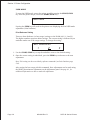
USER MODE
To enter the USER mode, power the printer on while pressing the START/STOP
key. After the printer beeps, release the START/STOP key.
USER MODE
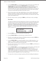
Pressing the FEED key will result in the printer now displaying the first USER mode
adjustment (Print Darkness).
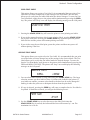
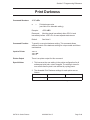
Print Darkness Setting
There are three Darkness (or heat range) settings on the XL400/410 (1, 2 and 3).
The higher numbers represent darker settings. The current setting is indicated by an
underline under one of the range settings. To change the setting:
PRINT DARKNESS
1
2
3
1. Use the START/STOP key to step the underline cursor to the desired setting.
2. Once the correct setting is underlined, press the FEED key to advance to the next
adjustment.
Note: This setting can be orverriden by software commands (see Print Darkness page
5-49.
After setting the heat range with this command, finer adjustments can be made using
the PRINT potentiometer adjustment on the Adjustment panel. See page 4-1 for
additional information on how to make this adjustment.
Page 3-8
9001038 Rev. D
SATO XL Series Printers
Section 3. Printer Configuration
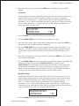
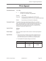
Print Speed Adjustment
There are three SPEED settings on the XL410 (4 ips, 5 ips and 6 ips) and four on the
XL400 (5 ips, 6 ips, 7 ips and 8 ips). They are listed on the bottom line of the display.
The current setting is indicated by an underline cursor under one of the speed
settings. To change the setting:
PRINT SPEED
4
5 6
1. Use the START/STOP key to step the underline cursor to the desired speed setting.
2. Once the correct setting is underlined, press the FEED key to advance to the next
adjustment.
Note: This command can be overriden by software command (see Print Speed, page
5-53).
See Section 4: CLEANING AND MAINTENANCE, for additional information on how to
make this adjustment for optimum print quality.
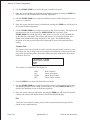
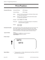
VH Offset
The Vertical and Horizontal offset allows you to move the label image both
horizontally and vertically to position a label format correctly on a label. This allows
you to use smaller label formats on media which is larger than the original format
called for without having to individually correct each H and V field positions in the
command stream. It is the same effect as using the <ESC>A3 Base Reference Point
command (page 5-17).
VH OFFSET
V: +000
+H: 000
1. Use the START/STOP key to select the vertical direction (“+” or “-”).
2. Once the correct direction is displayed, press the FEED key to accept the setting
advance to the vertical setting adjustment.
3. The underline cursor is now positioned under the least significant digit of the V offset
setting. The vertical offset will increase each time the START/STOP key is pressed.
If the START/STOP key is pressed and held down, the value will count up rapidly.
4. Once the correct vertical offset is displayed, press the FEED key to accept the setting
and advance to the horizontal setting adjustment.
5. Use the START/STOP key to select the horizontal direction (“+” or “-”).
6. Once the correct direction is displayed, press the FEED key to accept the setting
advance to the horizontal setting adjustment.
SATO XL Series Printers
9001038 Rev. D
Page 3-9
Section 3. Printer Configuration
Original Print
Line Position
ABCDEFG
Moved with both
Vertical and (+)
Horizontal Offset
Inside Edge
Feed Direction
ABCDEFG
7. The underline cursor is now positioned under the least significant digit of the H offset
setting. The horizontal offset will increase each time the START/STOP key is
pressed. If the START/STOP key is pressed and held down, the value will count up
rapidly.
8. Once the correct setting is displayed, press the FEED key to accept the setting advance
to the next adjustment.
Zero Slash Setting
This setting determines if a zero is printed with a slash or without a slash. This setting
can also be controlled via softwware commands. When YES is selected, the XU, XS,
XM, XB, XL and vector fonts will have a slash through the center of the zero character.
ZERO SLASH
YES
NO
1. Use the START/STOP key to step the underline cusor to either the YES or NO
selection.
2. Once the correct setting is underlined, pressing the FEED key will cycle back to the
Exit
You exit from the USER MODE by removing power from the printer. At this time the
values selected will be stored in non-volatile memory.
Page 3-10
9001038 Rev. D
SATO XL Series Printers
Section 3. Printer Configuration
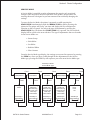
SERVICE MODE
A Service Mode is provided to make adjustments that require only occasional
changes. Since they affect the basic operation of the printer, the procedure for
entering this mode is designed to prevent someone from accidently changing the
settings.
To enter the Service Mode, the printer is powered on while pressing the
START/STOP simultaneously with the MEDIA TYPE key while powering the
printer on.The printer will “beep” one time and display the first configuration
selection on the LCD panel. You select the type of adjustment by pressing the
START/STOP key. Each time the START/STOP key is pressed, the Service Mode
display will be cycled to the next selection. The type of adjustments that can be made
in the Service Mode are:
• Sensor Setup
• Pitch Offset
• Cut Offset
• Backfeed Offset
• Clear Counter
From the Service Mode type display, the settings are accessed in sequence by pressing
the FEED key. Once you have cycled through all the adjustments for the Service
Mode type, pressing the FEED key will sequence you to the next Service Mode type.
Start/Stop to Select
Service Mode Type
Feed
Feed
Feed
Service Mode
Setup Sensor
Service Mode
Pitch Offset
Service Mode
Cut Offset
Feed
Feed
Feed
Feed
Service Mode
Backfeed Offset
Feed
Feed
Service Mode
Counter Clear
Feed
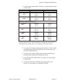
Gap
I-Mark
Center Hole Tag
I-Mark Tag
Side Hole Tag
R-Corner Tag
Label Gap
Label I-Mark
Center Hole Tag
I-Mark Tag
Side Hole Tag
R-Corner Tag
Label Gap
Label I-Mark
Center Hole Tag
I-Mark Tag
Side Hole Tag
R-Corner Tag
Label Gap
Label I-Mark
All
None
Head
Cut
Start/Stop to
SelectSetting
Start/Stop to
Select Settings
Start/Stop to
Select Settings
Start/Stop to
Select Settings
Start/Stop to
Select Settings
Feed
SATO XL Series Printers
Feed
Feed
9001038 Rev. D
Feed
Feed
Page 3-11
Section 3. Printer Configuration
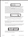
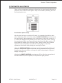
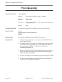
Setup Sensor
SERVICE MODE
SENSOR SETUP
The XL Series printers determine the location of the leading edge of the label or tag
by measuring the difference between light levels when it sees either a media edge or
a black I-Mark. This adjustment allows you to manually set the threshold voltage
level, between the maximum and minimum light levels. The type of sensor is
automatically selected by the MEDIA TYPE setting (Note: GAP is also used for tags).
The LCD will display either “GAP” or “I-Mark”on the top line along with the current
setting. If the value entered is “0.0V”, then the printer will automatically calculate the
setting when the first label is fed after the printer is powered on or the head is closed.
There are some instances where the automatically calculated value must be adjusted
to ensure reliable label feeding, such as when the backing opacity or the reflectance
of the I-Mark varies significantly within a roll of labels or between label rolls. In these
instances the value should be set using the following procedures.
GAP
INPUT
(X.XV)
(X.XV)
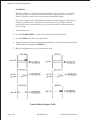
GAP - When setting the “gap” threshold, the voltage must be measured with nothing
(or nothing but the backing if labels are used) in the sensor and then again with a
labels in the sensor. The smaller value is added to the larger and the result
multiplied by 0.5. This is the starting point to be used. The formula for this is:
(High Voltage Level + Low Voltage Level) x 0.5 = Start Value
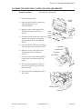
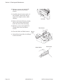
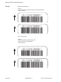
1. Insert a tag/label into the sensor (see page 2-11 for location of the sensors) and close
the Media Hold Down. Record the voltage shown on the top line of the LCD panel.
This line should have the message “GAP” on the top line. Make sure the tag/label is
all the way under the sensor.
2. If labels are used, strip the label from the backing and insert the backing strip under the
sensor. If tags are used, remove the tag from the sensor. Close the Media Hold Down.
Record the voltage shown on the top line of the LCD panel. The voltage ranges
measured should be within the following ranges:
Tag or
Label with Backing
No Tag or Label
Backing Only
2.0V to 3.5V
Less than 1.0V
If the measured values are outside this range, you may have trouble in finding a value
that will work properly under all conditions. If this is the case, a higher quality label
may be needed to get adequate performance.
Page 3-12
9001038 Rev. D
SATO XL Series Printers
Section 3. Printer Configuration
3. Calculate the starting point voltage using the formula.
4. Use the START/STOP key to step the counter to the desired setting. The display will
increment one step for each time the Start/Stop key is pressed. If the
START/STOP key is held pressed for more than two seconds, it will automatically
go into the fast scroll mode. The reading will advance to a setting of 4.9 (the
maximum voltage) after which it will automatically wrap and start at “0.0” again. If a
value of “0.0” is set, the printer will automatically set the level half way between the
two measured voltages each time the printer is powered on with labels loaded.
5. Repeat this procedure using values slightly higher or lower until the optimum
performance is obtained. If you cannot find a setting between the high and low
readings that gives adequate performance, then the label stock has too much
variation in its opacity and a better quality stock should be used.
6. Once the setting is correct, pressing the FEED key will advance to the next display.
I-Mark - When setting the “I-Mark” threshold, the voltage must be measured with
nothing but the label or tag under the sensor and then again with the printed I-Mark
under the sensor. The smaller value is added to the larger and the result multiplied
by 0.5 . This is the starting point to be used. The formula for this is:
(High Voltage Level + Low Voltage Level) x 0.5 = Start Value
1. Insert a label or tag into the sensor (see Section 4: Cleaning and Maintenance for
location of the sensors) and close the Media Hold Down. Make sure the printed
I-Mark is not under the sensor. Record the voltage shown on the top line of the LCD
panel. This line should have the message “I-Mark” on the top line.
2. Now pull the label or tag forward until the I-Mark is positioned under the sensor (the
voltage reading should be at its highest point). Record the voltage shown on the top
line of the LCD panel. The voltage ranges measured should be within the following
ranges:
Label or Tag Only
I- Mark
Less than 1.0V
2.5V to 3.5V
If the measured values are outside this range, you may have trouble in finding a value
that will work properly under all conditions. If this is the case, a higher quality label
may be needed to get adequate performance.
3. Calculate the starting point voltage using the formula.
SATO XL Series Printers
9001038 Rev. D
Page 3-13
Section 3. Printer Configuration
4. Use the START/STOP key to step the counter to the desired setting. The display will
increment one step for each time the START/STOP key is pressed. If the
START/STOP key is held pressed for more than two seconds, it will automatically
go into the fast scroll mode. The reading will advance to a setting of 4.9 (the
maximum voltage) after which it will automatically wrap and start at “0.0” again. If a
value of “0.0” is set, the printer will automatically set the level each time the printer
is powered on with labels/tags loaded or the head is closed.
5. Repeat this procedure using values slightly higher or lower until the value that gives
adequate performance is found. If adequate performance cannot be obtained, then
the label stock or printed I-Mark has too much variation in its reflectance and a better
quality stock should be used.
6. Once the setting is correct, pressing the FEED key will advance to the next display.
Pitch Offset
The Pitch is the distance from the leading edge of a label or tag to leading edge of the
next label or tag. It is used to position the first print line of the label or tag under the
print head. This position can be adjusted relative to the “000” reference line (see
page 3-26) +/- 99 dots in increments of 1 dot using the following procedure (1 dot =
.005" for the XL400 and .0033" for the XL412). Once the position is set, it can be
adjusted +/- 3.75 mm using the PRINT POSITION potentiomenter on the Control
panel (see page 3-19).
Pitch OFFSET
CENTER HOLE TAG
+ 99
1. Press the FEED key to enter the desired Service Mode type.
2. Use the START/STOP key to select the type of media to be used.
3. Once the correct media type is shown in the display message, pressing the FEED key
will advance to the Pitch Direction adjustment.
4. Use the START/STOP key to step the underline cursor to either the positive (+) or
negative (-) selection. A positive selection increases the label pitch (or label length)
while a negative selection decreases the label pitch.
5. Once the correct direction setting is underlined, pressing the FEED key will advance to
the Pitch Offset adjustment.
6. Use the START/STOP key to step the counter to the desired position. The display will
increment one step for each time the START/STOP key is pressed. If the
START/STOP key is held pressed for more than two seconds, it will automatically
go into the fast scroll mode. The reading will advance to a setting of 99 dots after
which it will automatically wrap and start at “00” again. The Pitch Direction set in the
previous step will be displayed in front of the Offset setting.
7. You may wish to check your settings by printing a label after making the adjustment.
Page 3-14
9001038 Rev. D
SATO XL Series Printers
Section 3. Printer Configuration
8. Once the setting is correct, pressing the FEED key will advance to the Cut Offset
display.
Cut Offset
The Cut Offset is the distance from the reference line (see page 3-20)of a label or tag
to the desired cut position. The cut position of the label or tag can be adjusted
relative to the reference line +/- 99 dots in increments of 1 dot using the following
procedure (1 dot = .005" for the XL400 and .0033" for the XL412). Once the position
is set, it can be adjusted +/- 3.75mm using the CUT POSITION potentiomenter on
the Control panel (see page 3-20).
CUT OFFSET
CENTER HOLE
+ 99
1. Press the FEED key to enter the desired Service Mode type.
2. Use the START/STOP key to select the type of media to be used.
3. Once the correct media type is shown in the display message, pressing the FEED key
will advance to the Cut Offset direction adjustment.
4. Use the START/STOP key to step the underline cursor to either the positive (+) or
negative (-) selection. A positive selection moves the cut position towards the top of
the tag while a negative selection moves the cut position toward the bottom of the
tag.
5. Once the correct direction setting is underlined, pressing the FEED key will advance to
the Cut Offset adjustment.
6. Use the START/STOP key to step the counter to the desired position. The display will
increment one step for each time the START/STOP key is pressed. If the
START/STOP key is held pressed for more than two seconds, it will automatically
go into the fast scroll mode. The reading will advance to a setting of 99 dots after
which it will automatically wrap and start at “00” again. The Cut Offset Direction set
in the previous step will be displayed in front of the Cut Offset setting.
Backfeed Offset
The Backfeed Offset is the distance the label or tag is to be retracted after it is cut. It
aligns the print and cut position of the first tag after tags have been ejected from the
printer. The backfeed distance can be adjusted relative to the reference line +/- 12
dots (+/- 18 dots for the XL410) in increments of 1 dot using the following
procedure (1 dot = .005" for the XL400 and .0033" for the XL410). A minus value
retracts the tag less and a positive value pulls the tag further back into the printer.If a
value greater than 12 (or 18) is entered, an error will occur.
BACKFEED OFFSET
CENTER HOLE
+ 10
1. Press the FEED key to enter the desired Service Mode type.
SATO XL Series Printers
9001038 Rev. D
Page 3-15
Section 3. Printer Configuration
2. Use the START/STOP key to select the type of media to be used.
3. Once the correct media type is shown in the display message, pressing the FEED key
will advance to the Backfeed Offset direction adjustment.
4. Use the START/STOP key to step the underline cursor to either the positive (+) or
negative (-) selection.
5. Once the correct direction setting is underlined, pressing the FEED key will advance to
the Backfeed Offset adjustment.
6. Use the START/STOP key to step the counter to the desired position. The display will
increment one step for each time the START/STOP key is pressed. If the
START/STOP key is held pressed for more than two seconds, it will automatically
go into the fast scroll mode. The reading will advance to a setting of 99 dots after
which it will automatically wrap and start at “00” again. The Backfeed Offset
Direction set in the previous step will be displayed in front of the Backfeed Offset
setting.
Counter Clear
The Counter Clear Service Mode is used to reset the internal printer counters to zero.
This allows the user to keep track of the number of centimeters of label material that
has passed through the printer, how many labels have been dispensed or how many
labels have been cut.
COUNTER CLEAR
NON
The counters are identified in the display as:
NON:
ALL:
HEAD:
CUT:
None (default)
Clears all counters
Clears Head Counter
Clears Cutter Counter
1. Press the FEED key to enter the desired Service Mode.
2. Use the START/STOP key to step the underline cursor to the counter(s) to be reset.
The default position is None (NON) of the counters. Use the START/STOP key to
advance the underline cursor to the desired position.
3. Once the correct setting is underlined, pressing the FEED key will clear the selected
counter and advance the display back to the SETUP SENSOR display.
Exit
To exit the Service Mode, remove power from the printer and the settings will be
stored in non-volatile memory.
Page 3-16
9001038 Rev. D
SATO XL Series Printers
Section 3. Printer Configuration
USER TEST PRINT
This option allows you to print a Test Label. It is recommended that you print a Test
Label after you have changed any of the settings in the User Mode. The test label
allows you to verify that you indeed did make the desired changes. To enter the User
Test Print Mode, apply power to the printer while simultaneously pressing the FEED
key. The printer will “beep” once and display the following message on the LCD panel:
USER TEST PRINT
1. Pressing the START/STOP key will cause the printer to start printing test labels.
2. If you wish to pause the printer after it starts printing labels, pres the START/STOP
key to place it Off Line. Pressing the START/STOP key again will place the printer
back On Line and the printer will resume printing test labels.
3. If you wish to stop the test label print, pause the printer and then turn power off
without placing it On Line.
SERVICE TEST PRINT
This option allows you to print a Service Test Label. It is recommended that you print
a test label after you have changed any of the settings in the Service Mode. The Test
Label allows you to verify that you indeed made the desired changes. To enter the
Service Test Print Mode, apply power to the printer while simultaneously pressing the
FEED and MEDIA TYPE keys. The printer will “beep” once and display the following
message on the LCD panel:
SERVICE PRINT
SMALL
LARGE
1. You can select either a Small or Large label using the START/STOP key. The Large
selection assumes you have labels at least 3.1 inches wide loaded in the printer. If
your labels are smaller, you must select Small as the head can be easily damaged if
nothing is under the print area to dissipate the heat from the print head.
2. If Large is selected, pressing the FEED key will cause a complete Service Test label to
be printed. If Small was selected, you will get the following screen:
PRINT SIZE
04 cm
3. Use the START/STOP key to select the correct size label. Each time the
START/STOP key is pressed, the indicated label size will increase by 1 cm. The
maximum size is 10 cm.
SATO XL Series Printers
9001038 Rev. D
Page 3-17
Section 3. Printer Configuration
4. Presing the FEED key will start the Small Service Print Test label print mode. The
printer can be paused by pressing the FEED key again.
5. To exit the Service Print Test Mode, pause the printer using the FEED key and then
remove power.
Page 3-18
9001038 Rev. D
SATO XL Series Printers
Section 3. Printer Configuration
POTENTIOMETER ADJUSTMENTS
There are four potentiometer adjustments located on the Control panel underneath a
protective cover at the rear of the printer. They are accessible by loosening the screw
and removing the cover.
Print Position (Pitch Offset)
After the pitch has been set with the LCD panel, it is sometimes desirable to make
minor adjustments. This can be done using the PRINT POSITION potentiometer on
the control panel. This potentiometer is set at the factory so that it has a range of +/3.75 mm. The midpoint setting should have no effect on the print position. Turning
the potentiometer all the way counterclockwise should move the print position 3.75
mm towards the leading edge of the tag or label. Turning it all the way clockwise
should move the print position away from the leading edge 3.75 mm. This
adjustment is best made while printing the actual tags or labels.
Adjust the PRINT POSITION potentiometer on the front panel until the first print
position is at the desired location on the label. If the potentiometer does not have
enough range, then you will have to change the pitch setting using the LCD panel
display. (see page 3-14)
Adjusting the PRINT POSITION potentiometer will not affect the stop position of
the label and the cut/tear-off position, it only affects the print position.
SATO XL Series Printers
9001038 Rev. D
Page 3-19
Section 3. Printer Configuration
Cut Position
When the printer is in the Cut mode (cutter enabled), the Cut Offset is set using the
LCD Service Mode to correctly position the label for cutting. Once the correct Cut
Offset is obtained, it may be necessary to adjust the position slightly.
This is done with the CUT POSITION potentiometer on the front panel. When turned
all the way clockwise the cut position is moved down the tag 3.75mm and when
turned all the way counterclockwise, the cut position is moved 3.75mm toward the
top of the tag.
1. Turn the printer on.
2. Press the START/STOP key to place the printer in the OFF LINE status.
3. Press the FEED key to feed out a blank label.
4. Adjust the position using the Cut Position potentiometer on the Control panel and feed
another label by depressing the FEED key.
5. When the adjustment is correct, turn the printer off.
Default Offset Settings, XL400
Page 3-20
9001038 Rev. D
SATO XL Series Printers
Section 3. Printer Configuration
Display
This potentiometer is used to adjust the contrast of the LCD display for optimum
viewing under various lighting conditions.
Print Darkness
There are three Print Darkness settings that can be set either via the LCD panel or
with softwware commands. The Print Darkness potentiometer allows you to fine tune
the darkness. Turning the potentiometer all the way counterclockwise will decrease
the amount of heat (lighter print) and truning it all the way Clockwise will increae
the amount of heat (darker print).
SATO XL Series Printers
9001038 Rev. D
Page 3-21
Section 3. Printer Configuration
This page left intentionally blank.
Page 3-22
9001038 Rev. D
SATO XL Series Printers
SECTION 4.
CLEANING AND MAINTENANCE
INTRODUCTION
This section provides information on user maintenance for the XL Series printers. The
following information is covered in this section:
• Adjusting the Print Quality
• Cleaning the Print Head, Platen and Rollers
PROCEDURES
ADJUSTING THE PRINT QUALITY
The XL printers are equipped with two different methods of adjusting the quality of
the print: print darkness and speed. When adjusting the printer for optimum print
quality, a bar code verifier system should be used. The human eye is a poor judge of
the relative widths of the bars in a symbol, a characteristic that is extremely
important for good bar code quality.
Darkness (Print)
This adjustment allows the user to control (within a specified range) the amount of
power that is used to activate the individual print head heat elements. It is important
to find a proper print darkness level based on your particular label and ribbon
combination. The printed images should not be too light nor should the ink from the
ribbon “bleed.” The edges of each image should be crisp and well defined.
LCD Panel - The Print Darkness can be set using the front panel LCD panel (see
page 3-8) or by downloading the setting using the Print Darkness software command
(see page 5-49). There are three ranges, 1 (Low), 2 (Medium) and 3 (High). Once
the range has been selected, the DARKNESS potentiometer on the Control panel can
be used to make finer adjustments.
DARKNESS Potentiometer - The fine adjustment for Print Darkness is the
Darkness potentiometer on the operator panel. It provides a continuous range of
adjustment, allowing you to make precise changes. Use a small cross-point
screwdriver, turning clockwise for darker print and counterclockwise for lighter print.
See Section 3: Configuration for instructions on performing potentiometer
adjustments.
NOTE: The PRINT potentiometer adjustment will affect the darkness in all of the
command code speed ranges, i.e. if the PRINT potentiometer is adjusted for lighter
print, the darkness will be lighter in all speed ranges selected by the command code.
SATO XL Series Printers
9001038 Rev. D
Page 4-1
Section 4. Cleaning and Maintenance
Print Speed
The other method of controlling print quality is by controlling the speed at which the
label is printed. This adjustment is made on an individual label basis using the either
the Print Speed command code or the LCD display panel . For more details on this
command, see page 5-53 in Section 5: Programming. Changing the print speed allows
the user to control the amount of time allowed for print element cooling before the
media is stepped to the next print position. It is especially critical when printing
“ladder” bar codes (bar codes printed with the bars parallel to the print line). When
printing a “ladder” bar code, it is important to allow the head to cool sufficiently
before stepping to the next position. If it does not have sufficient time to cool, the bar
will be “smeared” on the trailing edge.
The Print Speed can be set to 5, 6, 7 or 8 inches per second for the XL400 or 4, 5 or 6
for the XL410 using the LCD panel (see page 3-9) or with the Print Speed command
code (see page 5-53). The software command will override the any setting entered
using the LCD panel.
Page 4-2
9001038 Rev. D
SATO XL Series Printers
Section 4. Cleaning and Maintenance
CLEANING THE PRINT HEAD, PLATEN, ROLLERS AND SENSORS
Supplies needed:
SATO SA070 Cleaning Kit
1. Power the printer Off.
Ribbon
Roller
2. Open the print head by rotating the
green Head release lever
counterclockwise.
3. Moisten a cotton swab with SATO
Thermal Print Head and Platen
Cleaner.
Print
Head
4. Carefully rub the cotton swab over the Platen
Roller
length of the print head and along
and around the Platen and Ribbon
Rollers.
5. Open the Media Hold Down by lifting
up on the green plate marked “Push”.
6. Moisten a cotton swab with SATO
Thermal Print Head and Platen
Cleaner.
Nip Roller
Label Sensor
Tag Sensor
Feed Roller
7. Use the swab to clean the Nip Roller,
Feed Roller, Label Sensor and Tag
Sensor.
8. Place the Cleaning Sheet under the
Print Head (dull side up) and close
the Print Head.
9. Slowly pull the Cleaning Sheet out of
the printer.
Cleaning Sheet
Print Head
SATO XL Series Printers
9001038 Rev. D
Page 4-3
Section 4. Cleaning and Maintenance
10. Moisten a cotton swab with SATO
Thermal Print Head and Platen
Cleaner.
11. Carefully clean the entire surface of
the Cut Roller. Rotate the roller to
expose the complete surface while
cleaning.
Cut Roller
12. Remove the Sensor Plate by pressing
down on the detent latch located
inside the Sensor Plate mounting
13. Moisten a cotton swab with SATO
Thermal Print Head and Platen
Cleaner.
14. Clean the Pitch and I-Mark sensors.
Pitch Sensor
Sensor
Plate
4. Reinstall the Sensor Plate by sliding it
back on the shaft.
I-Mark Sensor
Page 4-4
9001038 Rev. D
Pitch Sensor
SATO XL Series Printers
SECTION 5.
PROGRAMMING
INTRODUCTION
This section presents the commands that are used with the SATO XL Series printers to
produce labels with logos, bar codes and alphanumeric data. All of the XL commands
use the same syntax. Some commands reference a physical point on the label using
horizontal and vertical dot reference numbers. The allowable range for these
references is dependent upon the particular printer to accomodate different print
widths and resolutions. These differences are noted in tables under the commands
affected.
The following information is presented in this section:
• The SATO XL Programming Language
• Selecting Protocol Control Codes
• Using Basic
• The Print Area
• Command Codes
THE SATO XL PROGRAMMING LANGUAGE
A programming language for a printer is a familiar concept to most programmers. It is
a group of commands that are designed to use the internal intelligence of the printer.
The commands, which are referred to as XL Command Codes, contain non-printable
ASCII characters (such as <STX>, <ETX>, <ESC>) and printable characters.
These commands must be assembled into an organized block of code to be sent as
one data stream to the printer, which in turn interprets the command codes and
generates the desired label output. The programmer is free to use any programming
language available to send the desired data to the SATO XL Series printer.
The command codes used by the SATO XL Series Printers are based upon “Escape”
(1B hexadecimal) sequences. Typically there are four types of command sequences:
<ESC>{Command}
These commands generally tell the printer to perform a specific action, like “clear the
memory.”
<ESC>{Command} {Data}
Commands with this format tell the printer to perform a specific action which is
dependent upon the following data, like “print X labels”, where the value for X is
contained in the data.
<ESC>{Command} {Parameter}
SATO XL Series Printers
9001038 Rev. D
Page 5-1
Section 5. Programming Reference
These commands set the operational parameters of the printer, like “set the print
speed to 3.”
<ESC> {Command} {Parameter} {Data}
Some commands can contain both Parameter and Data elements, such as “print a
Code 39 symbol containing the data”.
SELECTING PROTOCOL CONTROL CODES
Protocol codes are the special control characters that prepare the printer to receive
instructions. For example, the <ESC> character tells the printer that a command
code will follow and the <ENQ> character asks for the printer status.
There are two pre-defined different sets of Protocol Control codes to choose from.
Each set is made up of six special characters. The Standard Protocol Control codes are
non-printable characters, and the Non-Standard Protocol Control codes are printable
characters. The Non-Standard set may be useful on host computers using protocol
converters or in an application where non-printable ASCII characters cannot be sent
from the host. This manual uses the Standard Protocol Control codes for all of the
examples. Alternately, the user may define and download a set of custom Protocol
Control Codes (see Appendix E).
The Protocol Control codes are selected by a DIP switch DSW2-7 on the Control panel
(see Section 3: Printer DIP Switch Configuration, page 3-2)
CONTROL
CHARACTER
STANDARD
DSW2-7 OFF
NON-STANDARD
DSW2-7 ON
DESCRIPTION
STX
02 Hex
7B Hex = {
Start of Data
ETX
03 Hex
7D Hex = }
End of Data
ESC
1B Hex
5E Hex = ^
Command code to follow
ENQ
05 Hex
40 Hex = @
Get printer status, Bi-Com mode
CAN
18 Hex
21 Hex = !
Cancel print job, Bi-Com mode
USING BASIC
It may be useful to test your XL printer using a BASIC program on a PC. You may also
write your actual production programs in BASIC. Whatever the reason, if you will be
working in BASIC, some of the following hints may help you get started:
1. Set the WIDTH of the output device to 255 characters to avoid automatically sending
<CR> and <LF> characters after every line. The command string should be
continuous and uninterrupted by <CR> and/or <LF> commands. The examples
given in this manual are printed on separate lines because they will not fit on one line
and do not contain any <CR> and/or <LF> characters. If these characters are
needed, they are explicitly noted by the inclusion of <CR> and <LF> notations.
Page 5-2
9001038 Rev. D
SATO XL Series Printers
Section 5. Programming Reference
2. If you are using the printer’s RS232 interface, it is necessary to set the COM port on the
PC such that the CTS and DSR signals will be ignored. Send your OPEN “COM”
statement in the following way:
OPEN “COM1:9600,E,8,1,CS,DS” AS #1
This sets the RS232 communication parameters of the host PC’s COM1 port for 9600
baud, Even parity, 8 Data bits, 1 Stop bit and directing the port to ignore the CTS
and DSR control signals.
3. You may want to minimize keystrokes and program size by assigning the <ESC>
character to a string variable since this character is used quite often.
The following two examples in BASIC show a typical example using these hints. Both
of these examples use the Standard Protocol codes.
Printing with the Parallel Port:
5
REM XL400 Parallel Example
Identifies the program as a XL400
parallel port print label. The “REM”
prevents this data from being sent to the
printer and displays it only on the
screen.
10 E$=CHR$(27)
Sets the “E$” string as an <ESC>
character
20 WIDTH “LPT1:”,255
Sets the width of the output to 255
characters
30 LPRINT E$;"A";
Sends an “<ESC>A” command code to
the LPT1 parallel port
40 LPRINT E$;"H400";E$;"V100";E$;"XL1SATO";
Sends the data “SATO” to be to be
placed 400 dots horizontally and 100
dots vertically on the label and printed in
the “XL” font.
50 LPRINT E$;"Q1";
Instructs the printer to print one label.
60 LPRINT E$; “Z”;
Tells the printer that the last command
has been sent. The printer can now
create and print the job.
Printing with the RS232 Port:
5
REM XL400 RS232 Example
Identifies the program as a XL400
RS232 port print label. The “REM”
prevents this data from being sent to the
printer and displays it only on the
screen.
10 E$=CHR$(27)
Sets the “E$” string as an <ESC>
character.
20 OPEN “COM1:9600,N,8,1,CS,DS” AS #1
Opens the COM1 port for output and
sets the parameters as 9600 baud, No
parity, 8 Data bits, 1 Stop bit and
instructs the port to ignore the CTS and
DSR control signals.
SATO XL Series Printers
9001038 Rev. D
Page 5-3
Section 5. Programming Reference
30 PRINT #1,CHR$ (2);
Sends an <STX> (ASCII Code a
decimal “2”) to the printer instructing it
to prepare to receive a message.
50 PRINT #1,E$;"A";
Sends an “<ESC>A” command code to
Print Port #1 opened by statement 20
above.
60 PRINT #1, E$;"H400";E$;"V100";E$;"XL1SATO"; Sends the data “SATO” to be placed
400 dots horizontally and 100 dots
vertically on the label and printed in the
“XL” autosmoothed font.
50 PRINT #1, E$;"Q1";
Instructs the printer to print a quantity of
one label.
60 PRINT #1, E$; “Z”;
Tells the printer that the last command
has been sent. The printer can now
create and print the job.
70 PRINT #1,CHR$ (3);
Sends an <ETX> (ASCII Code decimal
“3”) to the printer telling it that this is the
end of the message.
THE PRINT AREA
The maximum print area for the various XL Series printers is listed in Table 5-1 on
page 5-5. Most of your label applications will not require labels that fill the entire
print area, therefore it is important to understand how to work with labels that do
not use the entire print area. The goal is to help you avoid printing where no label
exists, which may lead to print head damage, not to mention frustration when you
cannot see the printed output.
The diagram below illustrates the maximum print area and a sample 2 inch wide by 3
inch long label placed within this area. As can be seen, your label will be oriented
Max
Print
Width
Print Area
Max. Print
Length
Label
Feed
Direction
2"
3"
Normal
Reference
Point
H1, V1
Your
Label
Max. Print
Width minus 2"
Page 5-4
9001038 Rev. D
SATO XL Series Printers
Section 5. Programming Reference
against the inside left edge of the printer as viewed from the front of the printer. The
normal reference point is located at the H1, V1 position of the print area in the
normal print orientation (no rotation).
Table 5.1, Print Area
XL400
XL410
Resolution
203 dpi
8 dpmm
305 dpi
12 dpmm
Max Print Width
800 dots
3.9 in.
100 mm
1200 dots
3.9 in.
100 mm
Max Label Width
5.0 in.
128 mm
5.0 in.
128 mm
Std Print Length
1920 dots
9.5 in.
240 mm
2880 dots
9.5 in.
240 mm
Expanded Print Length Using Memory Card (2)
128 Kbyte
1168 dots
5.7 in.
146 mm
743 dots
2.4 in.
62 mm
512 Kbyte
4768 dots
23.5 in.
596mm
2977 dots
9.7 in.
248 mm
1 Mbyte
9360 dots (1)
46 in.
1170 mm
5956 dots
19.5 in.
496 mm
2 Mbyte
9999 dots (1)
49.2 in.
1249 mm
9999 dots (1)
32.8 in.
833 mm
(1). Limited by number of digits in command field.
(2). When a Memory Card is used to expand the print length, the card
capacity is used instead of the internal memory, not in addition to the
internal memory.
There are two methods available to make sure your printed output will appear
correctly on your label. They are as follows:
1. Send the Base Reference Point command as part of your data to the printer to set a
new base reference point for your label.
Calculate the distance (in dots) from the normal base reference point to the closest edge
of the label. For a 12 dpmm XL410 printer, this would be:
Label Width = 2" x 25.4 mm/in x 12 dpmm = 610 dots
For an 8 dpmm XL400 printer, this would be:
Label Width = 2" x 25.4 mm/in x 8 dpmm = 406 dots
SATO XL Series Printers
9001038 Rev. D
Page 5-5
Section 5. Programming Reference
The new Base Reference Point then becomes:
New Base Reference Point = Maximum Print Width - Label Width
For a XL410, the new Base Reference Point is
New Base Reference Point = 1200dots - 610 dots = 590dots
2. Use the normal base reference point from the print area and use the horizontal position
for each field to properly locate it on the label.
Calculate the distance (in dots) from the normal base reference point to the closest edge
of the label.
For a 12 dpmm printer, this would be:
Label Width = 2" x 25.4 mm/in x 12 dpmm = 610 dots
and for an 8 dpmm printer:
Label Width = 2" x 25.4 mm/in x 8 dpmm = 406 dots
New Base Reference Point = Maximum Print Width - Label Width
Each <ESC>H command would have the value “590” added to it to correctly position
each field.
The Command Code subsection contains a sample label output for each command
code. These samples reflect how the printed information would appear on a five inch
wide label. If you want to test any of the sample label outputs and are using labels
less than five inches in width, we suggest that you add the Base Reference Point
command to the data stream in order for the images to print on your labels.
You must be careful not to print off the label surface as the label provides a heat sink
for the print head elements. Doing so will cause irreparable damage to the head. This
damage is not covered under the print head warranty. The addition of the Base
Reference Point command to the sample data stream may help to adjust the print for
your labels. See the following two examples or refer to the Base Reference Point
command description.
For example, the following illustrates a sample data stream for a XL410 printer and
the resulting label assuming a 4.0 inch wide label:
<ESC>A
<ESC>H0050<ESC>V0100<ESC>L0303<ESC>XMSATO
<ESC>H0050<ESC>V0200<ESC>B103100*SATO*
<ESC>H0070<ESC>V0310<ESC>L0101<ESC>XUSATO
<ESC>Q1
<ESC>Z
Page 5-6
9001038 Rev. D
SATO XL Series Printers
Section 5. Programming Reference
Label
Label
4"
2"
If you are using a 2 inch wide label, the entire image may not appear on your label.
By adding the following Base Reference Point command to the second line of the data
stream, the base reference point will be changed, causing the image to be shifted over
toward the inside of the printer where it can be printed on the narrower label.
<ESC>A
<ESC>A3HV0590
<ESC>H0050<ESC>V0100<ESC>L0303<ESC>XMSATO
<ESC>H0050<ESC>V0200<ESC>B103100*SATO*
<ESC>H0170<ESC>V0310<ESC>L0101<ESC>XUSATO
<ESC>Q1
<ESC>Z
The image is moved horizontally to the right 2.0 inches (590 dots) so that it can be
printed on a 2 inch wide label.
For more information, see the Base Reference Point command description.
H=50
V=100
V=200
V=310
SATO
*SATO*
*SATO*
SATO
H=70
SATO XL Series Printers
4.0"
9001038 Rev. D
Page 5-7
Section 5. Programming Reference
SATO
SATO
*SATO*
*SATO*
*SATO*
*SATO*
2" Label
4.0"
ROTATED FIELDS
The XL Series printers can rotate each print field in 90° increments using the Rotate
command.
• <ESC>% - The field rotates, but the base reference point for the field
remains the same.
The following data stream will rotate the print field but will not change the base
reference point of the field:
<ESC>A<ESC>%1<ESC>V800<ESC>H200<ESC>L0202<ESC>XB1E<ESC>Q1<ESC>Z
Page 5-8
9001038 Rev. D
SATO XL Series Printers
Section 5. Programming Reference
Base
Ref
Point
H=200
E
Label
Feed
Direction
V=800
“%1”
COMMAND DEFAULT SETTINGS
There are some types of commands that must have a value specified before a label
can be printed. If the data stream does not contain these commands, a “default” value
is assumed. The commands and the corresponding default values are:
COMMAND
Print Rotation
Vertical Reference Point
Horizontal Reference Point
Character Pitch
Base Reference Point
Character Expansion
Print Darkness
Print Speed XL400
Print Speed XL410
Offset
DEFAULT
0°
0
0
2
H=1, V=1
1
2
6 ips
4 ips
NOTE
(1)
(1)
(1)
(1)
(2)
(1)
(1)
(2)
(2)
(3)
NOTES:
(1) The settings for these commands will revert to the default value when the printer
receives an <ESC>Z or an <ESC>*.
(2) The values transmitted with these commands will remain in effect until a new
command is received.
(3) The default value for offset depends upon the type of media selected.
Side Notch Tag Center Hole Tag
Label I-Mark
Side Hole Tag
Label Gap
I-Mark Tag
XL400
0.00
+040
4.5mm
XL410
0.00
+060
4.5mm
SATO XL Series Printers
9001038 Rev. D
Page 5-9
Section 5. Programming Reference
COMMAND CODES
This section contains all the XL Series printer Command Codes. The commands must
be sent to the printer in an organized fashion in order for the label(s) to print.
The purpose of this section is to:
1. Explain the different commands and provide examples of their usage.
2. To provide a detailed reference for programming the XL Series Printers.
Each command begins on a separate page with its own heading. A uniform layout is
used to help you find key information about each command. For each Command
Code in this section, there will be a sample data input stream to the printer and the
expected print output. By studying the examples, you can learn how to use the
particular command within a whole block of printer code. Pay particular attention to
the “Special Notes” with each command to learn other important information.
The subject commands are highlighted in bold letters in the Reference Sheets. There
are two parts of most, but not all, commands. The first is the command character
which immediately follows the <ESC> code. It is always an upper case alpha or a
special character (such as an “&” or a “%”). It is never a lower case alpha character. If
the command requires additional variable information, it is represented by a group of
lower case alpha characters immediately following the command character. For
example, if an aaaabb is listed following the basic command, the printer will look
for six characters immediately following the command. The first four would represent
the value of aaaa and the next two the value of bb.
The maximum number of characters defined in a parameter is represented by the
number of characters shown in the command structure. For example, a command
followed by an aaaa can have up to four characters. In general, commands with only
one parameter following the command can be entered without the leading zeroes.
However, certain commands require the exact number of matching characters. A
command with two parameters listed following the command code without a comma
delimiter, such as aaaabbbb require the exact number of digits to be entered. If the
value of aaaa is “800” and the value of bbbb is “300”, then the parameters must be
entered as “08000300”. It is recommended that you make it a practice to always
enter leading zeros to prevent any mistakes.
NOTE: These examples assume the use of the Standard Protocol Command Codes,
a parallel interface and a four inch wide label in a XL400 printer. The labels for all
other printers will be similar, but, because of different resolutions may be scaled
differently.
An alphabetical listing of the command codes is contained in Appendix A: Command
Code Quick Reference.
Page 5-10
9001038 Rev. D
SATO XL Series Printers
Section 5. Programming Reference
Bar Codes
Command Structure
Command Function
SATO XL Series Printers
1:3 narrow/wide bar ratio: <ESC>Babbcccd
2:5 narrow/wide ratio:
<ESC>BDabbcccd
1:2 narrow/wide bar ratio: <ESC>Dabbcccd
a
=
Bar Code Symbol
0 Codabar
1 Code 39
2 Interleaved 2 of 5 (I 2/5)
3 UPC-A / EAN-13
4 EAN-8
5 reserved
6 reserved
7 reserved
8 reserved
9 reserved
A reserved
B reserved
C reserved
D reserved
E UPC-E
F Bookland
G Code 128
I UCC 128
bb
=
Number of dots (01-12) for narrow bar and narrow space
ccc =
Bar height in dots (001-600)
d
UCC 128 only. Not used for other bar code types
0 No human readable text
1 Human readable at top
2 Human readable at bottom
=
Example:
<ESC>BD103200
Placement:
Immediately preceding data to be encoded
Default:
None
To print bar code images on a label. With this command, there are
nine standard bar code symbologies available to be printed and three
two dimensional symbols (see Two Dimensional bar code symbols
starting on page 5-89. Each of the bar codes are unique, and it is
important to know the differences. See Appendix B for specific
information on using each individual bar code symbol.
9001038 Rev. D
Page 5-11
Section 5. Programming Reference
Special Notes
1. UPC and EAN bar codes are not affected by the different types of
narrow to wide ratios. Instead, the <ESC>D command adds
descender bars to these codes where needed to meet UPC
specifications. The <ESC>BD command places decender bars in
the symbol.
2. The Code 128 and UCC 128 bar codes are not affected by the
narrow to wide ratios.
3. The Codabar and Code 39 bar codes are affected by the Character
Pitch command. This command must be placed before the Bar
Code command.
4. See Appendix B for more specific instructions and detailed
information regarding individual bar code symbols.
5. Because of their unique characteristics, two-dimensional symbols
are covered separately (see page 5-89).
6. For UCC128, the FNC1 code is automatically inserted and the Mod
10 and Mod 103 check digits are automatically calculated.
Page 5-12
9001038 Rev. D
SATO XL Series Printers
Section 5. Programming Reference
Bar Codes, Expansion
Command Structure
<ESC>BWaabbb
aa
=
bbb =
Command Function
Input to Printer:
Expansion factor by which the width of all bars and spaces
will be increased (01-12)
Bar height by dot (004-600 dots)
Example:
<ESC>BW02100
Placement:
Immediately follows the <ESC>BT command and
precedes data to be encoded.
Default:
None
This command works together with the <ESC>BT command to
specify an expansion factor and the bar code height for the particular
symbol being printed.
<ESC>A
<ESC>H0050<ESC>V0050<ESC>BD103100*XL400*
<ESC>H0050<ESC>V0050<ESC>BT101030103<ESC>BW04100*1234*
<ESC>Q1<ESC>Z
Printer Output:
Special Notes
1. This command must be preceded by the Variable Ratio Bar Codes
<ESC>BT command (see Page 5-14).
2. The following bar codes will be affected by the Character Pitch
command: Codabar and Code 39.
SATO XL Series Printers
9001038 Rev. D
Page 5-13
Section 5. Programming Reference
Bar Codes, Variable Ratio
Command Structure
<ESC>BTabbccddee
a
=
Bar Code Symbol:
0 Codabar
1 Code 39
2 Interleaved 2 of 5
bb
cc
dd
ee
=
=
=
=
Narrow space in dots (01-99)
Wide space in dots (01-99)
Narrow bar in dots (01-99)
Wide bar in dots (01-99)
Example:
<ESC>BT101030103
Placement:
Following print position commands and preceding
<ESC>BW
Default:
Current setting
Command Function
To print a bar code with a ratio other than those specified through the
standard bar code commands (B,BD, and D). This is done through
individual control of each of the bar code elements (bars, spaces) as
shown above. Remember that this command only applies to the three
bar code types shown.
Input to Printer:
<ESC>A
<ESC>H0050<ESC>V0050<ESC>BT101030103<ESC>BW03100*1234*
<ESC>Q1
<ESC>Z
Printer Output:
Page 5-14
9001038 Rev. D
SATO XL Series Printers
Section 5. Programming Reference
Special Notes
1. This command must be immediately followed by the <ESC>BW Bar
Code Expansion command (see Page 5-13).
2. You may use only one variable ratio bar code per label.
3. If the data specified in this command is incorrect, the command is
ignored and the ratio used will be based on the previous setting.
4. See Appendix B for more specific instructions and details regarding
individual bar code symbols.
SATO XL Series Printers
9001038 Rev. D
Page 5-15
Section 5. Programming Reference
Batch Separator
Command Structure
<ESC>Ia
a
=
1
Batch Marker- Prints a black mark on the edge of
the first tag of the print job.
b
=
1
Batch Separator - Cuts the first tag in a print job
2 mm longer and the following tag 2 mm shorter.
Example:
See Above
Placement:
Before or after job data stream
Default:
None
Command Function
To separate tag batches in the stacker.
Printer Input
<ESC>A<ESC>V0100<ESC>H0300< ESC>XMJob1<ESC>Q5<ESC>Z
<ESC>A<ESC>I1<ESC>Z
<ESC>A<ESC>V0100<ESC>H0300<ESC>WB1JOB2<ESC>Q5<ESC>I1<ESC>Z
Printer Output
1. If a Batch Separator tag is specified, the first 2 tags of the print job
are used. If these 2 tags are not to be used, you must increase
your print quantity by 2 tags to get the desired number of usable
tags.
2. If the Batch Separator Tag command is used in a separate print
job, you must specify a quantity of at least 2 tags or the command
will be ignored.
Page 5-16
9001038 Rev. D
SATO XL Series Printers
Section 5. Programming Reference
Base Reference Point
Command Structure
<ESC>A3H-aaaaVbbbb
-
Command Function
=
This character is optional. When present, it specifies that the
horizontal offset is in the negative direction. If it is left out,
the offset direction is positive.
aaaa =
Horizontal Print Offset (see Note 5 for field range)
bbbb =
Vertical Print Offset (see Note 5 for field range)
Example:
<ESC>A3H100V0050
Placement:
Preceding all images that are based on the new base
reference point
Default:
Current V and H offset setting in the printer configuration
To establish a new base reference point for the current label. The
base reference point is the top left corner or “origin” from where all
print position commands are based.
This command may be very helpful when using labels less than four
inches wide to place images on the printable label surface. It may
also be used to move images past preprinted fields on a label.
Input to Printer:
<ESC>A<ESC>L0202
<ESC>H0025<ESC>V0025<ESC>XBNORMAL REFERENCE POINT
<ESC>A3H0300V0075
<ESC>H0100<ESC>V0050<ESC>XBNEW REFERENCE POINT
<ESC>Q1<ESC>Z
Printer Output:
SATO XL Series Printers
9001038 Rev. D
Page 5-17
Section 5. Programming Reference
Special Notes
1. Use of this command will set the Vertical/Horizontal Offset setting of
the printer configuration until a new Base Reference Point
command is issued or the setting is changed from the operator
panel. See Section 3: Printer Configuration.
2. This command may be used more than once in a print job.
3. An alternative to using this command is to make changes to your
current Horizontal and Vertical Print Position commands (see
Page 5-50).
Example:
Let’s say the current base reference point is H=1, V=1 and you
wish to move all the fields on your label downward vertically by
150 dots. You could either (1) add the Base Reference Point
command or (2) change all the vertical position commands by an
additional 150 dots.
4. For a more detailed example of the Base Reference Point
command, see “Print Area” in this section (Page 5-4).
5. The allowable field ranges for this command depend upon the
setting of DSW2-2 and are:
Page 5-18
XL410
XL410
Horizontal
aaaa
0001 to 960
0001 to 1200
Vertical
bbbb
0001 to 1440
0001 to 2880
9001038 Rev. D
SATO XL Series Printers
Section 5. Programming Reference
Characters, Custom-Designed
Command Structure
Store Command: <ESC>Tabcc
Recall Command: <ESC>Kab90cc
a
=
1
2
b
=
Specifies the character encoding method for the data stream
H Hexadecimal characters
B Binary characters
cc
=
Memory location to store/recall the character. Valid memory
locations are 21 to 52 (counting in Hex) or “!” to “R” in Binary
(data)
=
16x16 matrix
24x24 matrix
Data to describe the character
Example:
<ESC>T1H3F
<ESC>K1H903F
See Appendix C for a more detailed explanation
Placement:
The Store command is typically sent in its own data
stream to the printer, between the Start/Stop commands.
The Recall command is sent in a secondary data stream
to print the character,and follows any necessary position
or size commands.
Default:
None
Command Function
To allow for the creation, storage, and printing of custom characters,
such as special fonts or logos. Up to 50 individual characters may be
stored in the custom character volatile memory.
Printer Input
See Appendix C for a detailed explanation.
<ESC>A
<ESC>T1H3F
0100038007C00FE01FF03FF87FFCFFFE07C007C007C007C007C007C007C007C0
<ESC>Z
<ESC>A
<ESC>H150<ESC>V100<ESC>L0505<ESC>K1H903F
<ESC>H350<ESC>V100<ESC>L1010<ESC>K1H903F
<ESC>Q1<ESC>Z
SATO XL Series Printers
9001038 Rev. D
Page 5-19
Section 5. Programming Reference
Printer Output
Special Notes
1. When printing the custom character using the Recall command, the
character is affected by the following commands:
Character Expansion (see Page 5-21)
Character Pitch (see Page 5-23)
Line Feed (see Page 5-44)
Rotate, Base Reference Point Fixed (see Page 5-59)
2. The characters are stored in volatile memory and must be reloaded
if the printer power is lost.
3. Do not use ASCII <CR> or <LF> characters (carriage return or line
feed) as line delimiters within the graphic data or the actual image
will not be printed as specified.
Page 5-20
9001038 Rev. D
SATO XL Series Printers
Section 5. Programming Reference
Character Expansion
Command Structure
<ESC>Laabb
aa
bb
=
=
Multiple to expand horizontally (01-12)
Multiple to expand vertically (01-12)
Example:
<ESC>L0305
Placement:
Preceding the data to be expanded
Default:
<ESC>L0101
Command Function
To expand characters independently in both the horizontal and
vertical directions. The command allows you to enlarge the base size
of each font (except the vector font) up to 12 times in either direction.
Expanded characters are typically used for added emphasis or for
long distance readability.
Input to Printer
<ESC>A
<ESC>A<ESC>H0100<ESC>V0100<ESC>XMSATO
<ESC>H0100<ESC>V0200<ESC>L0402<ESC>XMSATO
<ESC>H0100<ESC>V0300<ESC>L0204<ESC>XMSATO
<ESC>Q1<ESC>Z
Printer Output
SATO XL Series Printers
9001038 Rev. D
Page 5-21
Section 5. Programming Reference
Special Notes
This command will expand the following fonts:
1. Fonts XU, XS, XM, OA & OB (see Page 5-28) and fonts XB and XL
(see Page 5-32).
2. This command will also affect the following commands:
Character Pitch (see Page 5-23)
Characters, Custom-Designed (see Page 5-19)
3. The Character Expansion value is in effect for the current print job
until a new expansion command is specified.
4. The Line and Box command, if used within the data stream, may
return all subsequent text to the default expansion of 1 x 1.
Therefore, either send the Character Expansion command before
all printed data, or send Line and Box commands last, preceding
the <ESC>Q Quantity command.
Page 5-22
9001038 Rev. D
SATO XL Series Printers
Section 5. Programming Reference
Character Pitch
Command Structure
<ESC>Paa
aa
=
Number of dots between characters (00-99)
Example: <ESC>P03
Placement:
Preceding the text to be printed
Default:
<ESC>P02
Command Function
To designate the amount of spacing (in dots) between characters.
This command provides a means of altering character spacing for
label constraints or to enhance readability.
Input to Printer:
<ESC>A
<ESC>H0025<ESC>V0025<ESC>L0202<ESC>XB1SATO
<ESC>H0025<ESC>V0125<ESC>L0202<ESC>P20<ESC>XB1SATO
<ESC>H0025<ESC>V0225<ESC>L0202<ESC>P40<ESC>XB1SATO
<ESC>Q1<ESC>Z
Printer Output:
SATO XL Series Printers
9001038 Rev. D
Page 5-23
Section 5. Programming Reference
Special Notes
1. This command is affected by the <ESC>L Character Expansion
command (see Page 5-21). The character pitch is actually the
product of the current horizontal expansion multiple and the
designated pitch value.
Example:
<ESC>L0304
<ESC>P03
Pitch = (03) x (03) = 9 dots
2. To avoid confusion, you may want to include the <ESC>L
Character Expansion command and this command together in
your program.
3. This command affects fonts XU, XS, XM, XCS, XCL, OA & OB (see
Page 5-28, fonts XB and XL (see Page 5-32), and the vector font
(see Page 5-30).
4. Character Pitch will always revert to the default value unless it is
specified before each new font command in the data stream.
5. This command also affects Codabar and Code 39 bar codes.
Page 5-24
9001038 Rev. D
SATO XL Series Printers
Section 5. Programming Reference
Clear Print Job(s) & Memory
Command Structure
<ESC>*a
a
=
If the “a” parameter is not included with this command and
the printer is in the multi-buffer mode, this command clears
all print jobs in the printer memory, including the current
print job.
a
=
If “a” is included with this command, it specifies the internal
memory section to be cleared
T To clear the custom character memory
& To clear the form overlay memory
X To clear all internal memory
Example:
<ESC>*
<ESC>*X
Placement:
This command should be sent to the printer as an
independent data stream.
Default:
None
Command Function
To clear individual memory or buffer areas of the printer.
Input to Printer:
<ESC>A
<ESC>*
<ESC>Z
Printer Output:
There is no printer output as a result of this command. The current
print job in the buffer will be terminated and all other print jobs in the
buffer cleared.
Special Note
1. See Memory Card Functions for variations of this command used to
clear data from the memory card (Page 5-71).
2. It is not necessary to clear the printer’s memory between each print
job.
3. The primary purpose of this command is to clear all print jobs in the
multi-buffer mode. The “a” parameter can be used in either the
multi-buffer or single job mode to clear specific parts of the
memory.
4. When the “a” parameter is used, the section of memory specified
will not be cleared until the label is printed.
SATO XL Series Printers
9001038 Rev. D
Page 5-25
Section 5. Programming Reference
Copy Image Area
Command Structure
<ESC>WDHaaaaVbbbbXccccYdddd
aaaa =
Horizontal position of the top left corner of the area to be copied
bbbb =
Vertical position of the top left corner of the area to be copied
cccc =
Horizontal length of the image area to be copied
dddd =
Vertical length of the image area to be copied
Example:
<ESC>WDH0100V0050X0600Y0400
Placement:
Anywhere within the data stream, after specifying the
location of the duplicate image.
Default:
None
Command Function
To copy an image from one location to another on the same label.
This may be useful for duplicating individual fields or entire sections
of the label with only one command.
Input to Printer:
<ESC>A
<ESC>H0050<ESC>V0050<ESC>E010<ESC>XM
SATOSATOSATOSATOSATOSATOSATO
SATOSATOSATOSATOSATOSATOSATO
SATOSATOSATOSATOSATOSATOSATO
SATOSATOSATOSATOSATOSATOSATO
<ESC>H0180<ESC>V0250<ESC>WDH0130V0050X0400Y0200
<ESC>Q1<ESC>Z
Printer Output:
Page 5-26
9001038 Rev. D
SATO XL Series Printers
Section 5. Programming Reference
Special Notes
1. Use the Print Position commands (V and H) to locate the new area
for the duplicate image (see Page 5-50).
2. Position of the new target area must not be inside the original
image.
3. If you use the Rotate command, V, H, X and Y axes will be
reversed.
4. If the reference area of the target image exceeds the print area, it
will not be printed.
5. The allowable ranges for these fields are as follows:
XL400
XL410
Horizontal
aaaa
cccc
0001
to
0800
0001
to
1200
Vertical
bbbb
dddd
0001
to
1920
0001
to
2880
SATO XL Series Printers
9001038 Rev. D
Page 5-27
Section 5. Programming Reference
Fonts OA, OB, XU, XS & XM
Command Structure
Command Function
Font XU:
Font XS:
Font XM:
Font OA:
Font OB:
Example:
See above
Placement:
Preceding the data to be printed
Default:
None
To print text images on a label. These are eight of the built-in fonts
available on the printer. All matrices include descenders.
OA
OB
Input to Printer
<ESC>XU
<ESC>XS
<ESC>XM
<ESC>OA
<ESC>OB
NON-PROPORTIONAL
PROPORTIONAL
OCR-A font (see Note 7 for matrix) XU
5W x 9H dot matrix
OCR-B font (see Note 7 for matrix) XS
17W x 17H dot matrix
XM 24W x 24H dot matrix
<ESC>A
<ESC>H0100<ESC>V0100<ESC>L0202<ESC>XUSATO
<ESC>H0100<ESC>V0175<ESC>L0202<ESC>XSSATO
<ESC>H0100<ESC>V0250<ESC>L0202<ESC>XMSATO
<ESC>H0100<ESC>V0325<ESC>L0101<ESC>OASATO
<ESC>H0100<ESC>V0400<ESC>L0101<ESC>OBSATO
<ESC>Q1<ESC>Z
Printer Output
Special Notes
1. Characters may be enlarged through the use of the Character
Expansion command (see Page 5-21).
2. Character spacing may be altered through the use of the Character
Pitch command (see Page 5-23). The default is 2 dots between
Page 5-28
9001038 Rev. D
SATO XL Series Printers
Section 5. Programming Reference
characters. It is recommended to use a spacing of 5 dots for
OCR-A and 1 dot for OCR-B.
3. You may also create custom characters or fonts. See the <ESC>T
Custom-Designed Characters command (Page 5-19).
4. A font must be defined for each field to be printed. There is no
default font.
5. The proportionally spaced fonts XU, XS, XM, XL and XA can be
printed with fixed spacing using the <ESC>PS Proportional Space
command.
6. The matrices for the OA and OB fonts are scaled so that they will
remain a constant size according to the OCR-A and OCR-B
specifications when printed on different resolution printers.
SATO XL Series Printers
XL400
XL410
OA Font
15 dots W x 22 dots H
22 dots W x 33 dots H
OB Font
20 dots W x 24 dots H
30 dots W x 36 dots H
9001038 Rev. D
Page 5-29
Section 5. Programming Reference
Font, Vector
Command Structure
Specify Vector Font:
<ESC>$a,b,c,d
Data for Vector Font:
<ESC>$=(data)
a
=
b
c
d
=
=
=
A Helvetica Bold (proportional spacing)
B Helvetica Bold (fixed spacing)
Font width (50-999)
Font height (50-999 dots)
Font variation (0-9) as follows:
0 Standard
1 Standard open (outlined)
2 Gray (mesh) pattern 1
3 Gray (mesh) pattern 2
4 Gray (mesh) pattern 3
5 Standard open, shadow 1
6 Standard open, shadow 2
7 Standard mirror image
8 Italic
9 Italic open, shadow
Example:
<ESC>$A,100,200,0<ESC>$=123456
Placement:
Immediately preceding data to be printed.
Default:
None
Command Function
To specify printing of the unique SATO vector font. The vector font
allows large characters to be printed with smooth, round edges. Each
character is made of a number of vectors (or lines), and will require
slightly more printer compiling time.
Input to Printer
<ESC>A
<ESC>H0100<ESC>V0100<ESC>$A,100,100,0<ESC>$=SATO AMERICA
<ESC>H0100<ESC>V0200<ES C>$=VECTOR FONT
<ESC>$A,200,300,8<ESC>H0100<ESC>V0350<ESC>$=SATO
<ESC>Q1<ESC>Z
Page 5-30
9001038 Rev. D
SATO XL Series Printers
Section 5. Programming Reference
Printer Output
Special Notes
1. The Pitch command can be used with Vector fonts.
2. If the font size designation is out of the specified range, a default
value of 50 is used.
4. The font width and height values include asenders, desenders and
other space.
5. A font must be defined for each field to be printed. There is no
default font.
SATO XL Series Printers
9001038 Rev. D
Page 5-31
Section 5. Programming Reference
Fonts XB & XL
Command Structure
Command Function
Font XB:
Font XL:
<ESC>XBa
<ESC>XLa
a
0
1
Disables auto-smoothing of font
Enables auto-smoothing of font (see notes below)
Example:
<ESC>XB1123456
Placement:
Preceding the data to be printed
Default:
None
To print text images on a label. These are the two auto-smoothing
fonts available on the printer.
XB
XL
Input to Printer:
=
48W x 48H dot matrix
48W x 48H dot matrix
ESC>A
<ESC>H0001<ESC>V0100<ESC>XB0SATO
<ESC>H0001<ESC>V0185<ESC>XB1SATO
<ESC>H0001<ESC>V0270<ESC>XL0SATO
<ESC>H0001<ESC>V0355<ESC>XL1SATO
<ESC>Q1<ESC>Z
Printer Output:
Special Notes
1. Auto-smoothing (when enabled) is only effective if the character
expansion rate is at least (3) times in each direction.
2. Characters may be enlarged through the use of the <ESC>L
Character Expansion command (see Page 5-21).
Page 5-32
9001038 Rev. D
SATO XL Series Printers
Section 5. Programming Reference
3. Character spacing may be altered through the use of the <ESC>A
Character Pitch command (see Page 5-23).
4. A font must be defined for each field to be printed. There is no
default font.
SATO XL Series Printers
9001038 Rev. D
Page 5-33
Section 5. Programming Reference
Fonts XCS and XCL
Care Symbols
Command Structure
Font XCS: <ESC>XCS,{data}
Font XCL: <ESC>XCL,{data}
{data}
Command Function
=
ASCII code for Care Symbols
Example:
<ESC>XCS,0123ABC
Placement:
Preceding the data to be printed
Default:
None
To print Care Symbols images on a label. These are the four
auto-smoothing fonts available on the printer.
XCS 24W x 24H dot matrix
XCL 36W x 36H dot matrix
Input to Printer:
<ESC>A
<ESC>H0100<ESC>V0100<ESC>XCS,01AB
<ESC>H0100<ESC>V0185<ESC>XCL,01AB
<ESC>Q1<ESC>Z
Printer Output
Special Notes
Page 5-34
1. There are 34 Care Symbols in this font, in the ranges 03H to 08H,
14H to F4H, 05H to 85H and A5H. See Appendix F for font tables.
9001038 Rev. D
SATO XL Series Printers
Section 5. Programming Reference
Form Feed
Command Structure
<ESC>A(space)<ESC>Z
Example:
See above
Placement:
Separate data stream sent to printer
Default:
None
Command Function
To feed a blank tag or label, which is the equivalent of a “form feed”
Input to Printer
<ESC>A(space)
<ESC>Z
Printer Output
Blank label or tag
SATO XL Series Printers
9001038 Rev. D
Page 5-35
Section 5. Programming Reference
Form Overlay, Recall
Command Structure
<ESC>/
Example:
See above
Placement:
Must be preceded by all other data and placed just before
the Print Quantity command (<ESC>Q)
Default:
None
Command Function
To recall the label image from the form overlay memory for printing.
This command recalls a stored image from the overlay memory.
Additional or different data can be printed with the recalled image.
Input to Printer
<ESC>A
<ESC>H0100<ESC>V0125
<ESC>XSTHIS IS THE STORED IMAGE WITH A BARCODE
<ESC>H0100<ESC>V0165<ESC>B103100*12345*
<ESC>&<ESC>Z
<ESC>A<ESC>H0100<ESC>V0050
<ESC>XSTHIS IS RECALLING AND ADDING TO THE STORED IMAGE<ESC>/
<ESC>Q1<ESC>Z
Printer Output
Special Notes
Page 5-36
1. The overlay is stored using the <ESC>& Form Overlay Store
command (see Page 5-37).
9001038 Rev. D
SATO XL Series Printers
Section 5. Programming Reference
Form Overlay, Store
Command Structure
<ESC>&
Example:
See above
Placement:
Must be preceded by all other data and placed just before
the Stop command (<ESC>Z)
Default:
None
Command Function
To store a label image in the volatile form overlay memory. Only one
label image may be stored in this memory area at a time.
Input to Printer
<ESC>A
<ESC>H0001<ESC>V0125
<ESC>XSTHIS IS THE STORED IMAGE WITH A BARCODE
<ESC>H0001<ESC>V0165<ESC>B103100*12345*
<ESC>&
< ESC>Z
Printer Output
There is no output from this command. It stores the label image in the
overlay buffer.
Special Notes
1. Remember that this storage is volatile. Therefore, if the printer
loses power, the overlay must be sent again.
2. The overlay is recalled using the <ESC>/ Form Overlay Recall
command (see Page 5-36).
3. Form overlays do not have to be recompiled each time they are
called to be printed and therefore may result in much faster print
output.
SATO XL Series Printers
9001038 Rev. D
Page 5-37
Section 5. Programming Reference
Graphics, Custom
Command Structure
<ESC>Gabbbccc(data)
a
=
Specifies format of data stream to follow
B Binary format
H Hexadecimal format
bbb =
Number of horizontal 8 x 8 blocks (see Note 7 for allowable
range).
ccc =
Number of vertical 8 x 8 blocks (see Note for allowable range).
(data)=
Hex data to describe the graphic image
Example:
<ESC>GH006006
See Appendix C for a detailed example
Placement:
May be placed anywhere within the data stream after the
necessary position commands.
Default:
None
Command Function
To create and print custom graphics (logos, pictures, etc.) on a label.
The graphic image may be printed along with other printed data to
enhance label appearance or eliminate the need for preprinted label
stock. Using a dot-addressable matrix, design the graphic image in 8
dot by 8 dot blocks, then send it in a binary format to the printer.
Printer Input
<ESC>A
<ESC>H0100<ESC>V0100<ESC>GH006006
FFFFFFFFFFFFFFFFFFFFFFFFC00000000003
C00000000003C000FFFFFFF3C00080000013
C00080000013C0009FFFFF13C00080000013
C00080000013C0009FFFFF13C00080000013
C00080000013C000FFFFFFF3C00000000003
C00000000003C00000000003C00000000003
C00000000003C00000000003C00003C00003
C00007E00003C0000FF00003C0000FF00003
C0000FF00003C0000FF00003C00007E00003
C00003C00003C00003C00003C00003C00003
C00003C00003C00003C00003C00003C00003
C00003C00003C00003C00003C00003C00003
C00003C00003C00001800003C00000000003
C00000000003FFFFFFFFFFFFFFFFFFFFFFFF
<ESC>H0300<ESC>V0100<ESC>XSPLEASE PLACE YOUR DISK
<ESC>H0300<ESC>V0150<ESC>XSIN A SAFE PLACE
<ESC>Q1<ESC>Z
See Appendix C for a details on the data format.
Page 5-38
9001038 Rev. D
SATO XL Series Printers
Section 5. Programming Reference
Printer Output
Special Notes
1. Do not use ASCII <CR> or <LF> characters (carriage return or line
feed) as line delimiters within the graphic data or the actual image
will not be printed as specified.
2. A custom graphic cannot be enlarged by the <ESC>L Character
Expansion command (Page 5-21).
3. A custom graphic is not affected by either of the Rotation
commands. Therefore, always design and locate your graphic
image to print in the appropriate orientation.
4. Use an optional Memory Card to expand the print length.
5. To store graphic images in an optional memory card, see the
Memory Card Functions section.
6. The binary format reduces the transmission time by 50%.
7. The allowable number of blocks for this command are:
XL400
XL410
Horizontal Blocks
cccc
001 to 100
001 to 150
Vertical Blocks
cccc
001 to 240
001 to 360
SATO XL Series Printers
9001038 Rev. D
Page 5-39
Section 5. Programming Reference
Graphics, PCX
Command Structure
<ESC>GPaaaaa,(data)
aaaaa
=
Number of bytes to be downloaded
Example:
<ESC>GP32000, ... data...
Placement:
Anywhere within the job data stream
Default:
None
Command Function
To allow the creation and printing of graphic images using a PCX file
format.
Printer Input
See Appendix Appendix C for a detailed example
<ESC>A
<ESC>V0150<ESC>H0100<ESC>GP03800,(...Data...)
<ESC>Q1
<ESC>Z
Printer Output
Special Notes
1. The maximum number of bytes that can be downloaded is 32K
(compressed). The number specified by this command includes
the PCX header information. The maximum size of the
uncompressed PCX file is 64K. If the uncompressed file exceeds
64K, the graphic will not print.
2. Only black and white PCX files can be downloaded.
3. The image created by this command cannot be rotated.
4. The file size specified by this command is the DOS file size in bytes.
Page 5-40
9001038 Rev. D
SATO XL Series Printers
Section 5. Programming Reference
Job ID Store
Command Structure
<ESC>IDaa
aa
=
Job ID assigned (01 to 99)
Example:
<ESC>ID09
Placement:
Immediately following the <ESC>A in the job data stream.
Default:
None
Command Function
To add an identification number to a job. The status of the job can
then be determined using the ENQ command in the Bi-Com status
mode (See Section 5: Interface Specifications for more information).
Printer Input
<ESC>A
<ESC>ID02
. . . Job . . .
<ESC>Z
Printer Output
There is no printer output as a result of this command.
Special Notes
1. Works only in Bi-Com mode. The Job ID number must be stored
before Bi-Com status mode can be used.
2. If more than one ID number is sent in a single job, i.e.
<ESC>A
<ESC>ID01
..........
<ESC>ID02
.........
the last number transmitted will be used.
2. It is effective only for the current print job.
SATO XL Series Printers
9001038 Rev. D
Page 5-41
Section 5. Programming Reference
Lines and Boxes
Command Structure
Line
aa
b
<ESC>FWaabcccc
=
=
cccc =
Width of horizontal line in dots (01-99)
Line orientation
H
Horizontal line
V
Vertical Line
Length of line in dots (see Note 2 for max length)
Box:
<ESC>FWaabbVccccHdddd
aa =
bb =
cccc =
dddd =
Width of horizontal side in dots (01-99)
Width of vertical side in dots (01-99)
Length of vertical side in dots (see Note 2 for max length)
Length of horizontal side in dots (see Note 2 for max length)
Example:
<ESC>FW02H0200
Placement:
Following the necessary positioning commands
Default:
None
Command Function
To print horizontal lines, vertical lines, and boxes as images on the
label.
Input to Printer
<ESC>A
<ESC>H0100<ESC>V0100<ESC>FW20H0200
<ESC>H0320<ESC>V0100<ESC>FW20V0200
<ESC>H0350<ESC>V0100<ESC>FW1010H0200V0200
<ESC>Q1<ESC>Z
Printer Output
Special Notes
Page 5-42
9001038 Rev. D
SATO XL Series Printers
Section 5. Programming Reference
1. It is recommended that all lines and boxes be specified in the
normal print direction.
2. The maximum allowable lengths for the different XL printers are as
follows.
XL400
XL410
Horizontal
cccc
0001 to 0800
0001 to 1200
Vertical
cccc
0001 to 1920
0001 to 2880
SATO XL Series Printers
9001038 Rev. D
Page 5-43
Section 5. Programming Reference
Line Feed
Command Structure
<ESC>Eaaa
aaa =
Number of dots (001-999) between the bottom of the
characters on one line to the top of the characters on
the next line
Example:
<ESC>E010
Placement:
Preceding the text that will use the line feed function
Default:
None
Command Function
To print multiple lines of the same character size without specifying a
new print position for each line. With the Line Feed command, specify
the number of dots you want between each line. Then, send an ASCII
<CR> at the end of each line of text. The printer automatically
identifies the size of the last character, moves down the number of
dots specified, and begins printing the next line.
Input to Printer
<ESC>A
<ESC>E010<ESC>H0050<ESC>V0050<ESC>L0202<ESC>XS
THIS IS THE 1ST LINE
THIS IS THE 2ND LINE
THIS IS THE 3RD LINE
<ESC>Q1<ESC>Z
Printer Output
Special Notes
1. This command can be used for text and for bar codes.
2. It is effective only for the current data stream.
3. When printing lines or boxes in the same data stream with the Line
Feed command, the Lines and Boxes command should be
specified last, preceding <ESC>Q Quantity command.
Page 5-44
9001038 Rev. D
SATO XL Series Printers
Section 5. Programming Reference
4. This command is invalid only if the value specified is zero.
5. The rotation command can be used with this command.
6. Following this command with a <CR> character will allow you to
print with auto line feed. In this case, the print position will be
determined from the value specified in the command and the H
value set in the printer. However, if you specify several H values
after this command, the print position will be determined by the H
value last specified. You must redefine the font to be used after
each H command.
SATO XL Series Printers
9001038 Rev. D
Page 5-45
Section 5. Programming Reference
Media Size
Command Structure
<ESC>A1aabbbccc
aa
=
Media Type
0T
Center Hole, Side Hole, R-Corner or I-Mark tag
0L
I-Mark or Gap label
bbb =
Pitch Size in mm
025 - 120
Tag
019 - 120
Label
025 - 240
Tag
019 - 240
Label
cc
Media Width in mm
032 - 080
Tag
025 - 080
Label
032 - 100
Tag
025 - 100
Label
=
Example:
<ESC>A1OT060042
Placement:
Preceding the print job
Default:
None
Command Function
Checks if the Media Size specified in the job stream matches the
media size detected by the printer. DSW2-8 must be ON for this
command to work.
Input to Printer
<ESC>A
<ESC>A1OT038076
<ESC>Z
<ESC>A<ESC>V0100<ESC>H0400
<ESC>P2<ESC>L0202<ESC>XMABCD
<ESC>Q3<ESC>Z
Printer Output
There is no printer output as a result of this command.
Special Notes
1. A Media Size error will occur is the pitch and width sent by the
command does not match that measured by the printer.
2. If a Media Error occurs, you must either load the correct size media
or reset the printer by powering it Off.
Page 5-46
9001038 Rev. D
SATO XL Series Printers
Section 5. Programming Reference
Off-Line/Pause
Command Structure
<ESC>@,nnn...n
nnn...n
=
Display message, up to 32 ASCII characters
Example:
See above
Placement:
In its own data stream
Default:
None
Command Function
To specify the printer to come to an off-line state. When used within a
print job, the printer goes off-line after finishing the print job.
Input to Printer
<ESC>A
<ESC>@,Load Blue Tags - 1" W by 3" L
<ESC>Z
Printer Output
There is no printer output for this command. The printer is placed in
the Off-Line mode as soon as the current print job is finished.
Special Notes
1. You must press the START/STOP key on the front panel to return
the printer to an on-line status (see Control Panel in Section 3 of
this manual).
2. Can be used before or after a print job.
SATO XL Series Printers
9001038 Rev. D
Page 5-47
Section 5. Programming Reference
Print & Cut Offset
Command Structure
<ESC>#abbbb
a
=
bbbb =
Offset Direction
+ Feed Direction (plus offset)
- Reverse Direction (minimum offset)
Number of dots for offset (000 to 400)
Example:
<ESC>#+40
Placement:
In data stream for job
Default:
None
Command Function
To move the tag cut position.
Printer Input
<ESC>A
<ESC>#+040
<ESC>V0100<ESC>H0200<ESC>P2<ESC>L0202<ESC>WB1ABCD
<ESC>Q3<ESC>Z
Special Notes
1. This command can be specified for every print job and keeps the
specified value in memory as long as power is on.
Page 5-48
9001038 Rev. D
SATO XL Series Printers
Section 5. Programming Reference
Print Darkness
Command Structure
<ESC>#Ea
a
=
Example:
Print darkness value
(see Note 2 for allowable setting)
<ESC>#E2
Placement:
Must be placed immediately after <ESC>A and
immediately before <ESC>Z in its own separate data stream
Default:
See Note 2
Command Function
To specify a new print darkness setting. This command allows
software control of the darkness setting for unique media and ribbon
combinations.
Input to Printer
<ESC>A
<ESC>#E2
<ESC>Z
Printer Output
There is no printer output for this command.
Special Notes
1. This becomes the new setting in the printer configuration for all
subsequent print jobs, unless changed. The setting is stored in
non-volatile memory and is not affected by cycling power.
2. The allowable Print Darkness settings for each printer are as
follows:
XL400
Darkness Settings
XL410
1, 2 or 3
Default values are shown in bold type.
SATO XL Series Printers
9001038 Rev. D
Page 5-49
Section 5. Programming Reference
Print Position
Command Structure
Horizontal Position:
<ESC>Haaaa
Vertical Position:
<ESC>Vbbbb
aaaa =
Number of dots horizontally from the base reference point
(1 to maximum) See Note 2.
bbbb =
Number of dots vertically from the base reference point
(1 to maximum) See Note 2.
Example: <ESC>H0020<ESC>V0150
Placement:
Default:
Command Function
Input to Printer
Preceding any printed field description of lines/boxes,
fonts, bar codes or graphics.
<ESC>H0001
<ESC>V0001
The Horizontal and Vertical commands specify the top left corner of a
field or label, using the current base reference point as an origin.
They also establish a reference point for subsequent fields until the
next horizontal and/or vertical print position command is issued.
<ESC>A
<ESC>H0025<ESC>V0050<ESC>L0303<ESC>XMSATO
<ESC>H0100<ESC>V0150<ESC>XMSATO
<ESC>Q1<ESC>Z
Printer Output
Special Notes
Page 5-50
1. The print position of a field is affected by both the Rotate (<ESC>R
and <ESC>A3) commands.
9001038 Rev. D
SATO XL Series Printers
Section 5. Programming Reference
2. For print lengths greater than 9.5 inches, an optional Memory Card
must be used.
XL400
XL410
Maximum Print Width
aaaa
800 dots
3.9 in.
100 mm
1200 dots
3.9 in.
100 mm
Standard Print Length
bbbb
1920 dots
9.5 in.
240 mm
2880 dots
9.5 in.
240 mm
Maximum Length with Memory Card (2)
128 Kbyte
bbbb
1168 dots
5.7 in.
146 mm
743 dots
2.4 in.
62 mm
512 Kbyte
bbbb
4768 dots
23.5 in.
596 mm
2977 dots
9.7 in.
248mm
1 Mbyte
bbbb
9360 dots
46 in.
1170 mm
5956 dots
19.5in.
496 mm
2 Mbyte
bbbb
9999 dots (1)
49.2 in.
1249 mm
9999 dots (1)
32.8 in.
833 mm
(1) Limited by the number of digits in the command field.
(2) When a Memory Card is used to expand the print length, the card capacity is
used instead of the internal memory, not in addition to the internal memory.
3. If any part of an image is placed past the maximum number of dots
for standard length and or the capacity of the memory card, that
part of the image will be lost.
4. If any part of an image is placed past maximum allowable dots
across the label, that part of the image will be lost.
5. If you attempt to print where there is no paper, you may damage
the print head.
6. For these commands, the leading zeroes do not have to be
entered. The command V1 is equivalent to V0001.
SATO XL Series Printers
9001038 Rev. D
Page 5-51
Section 5. Programming Reference
Print Quantity
Command Structure
<ESC>Qaaaaaa
aaaaaa
=
Total number of labels to print (1-999999)
Example:
<ESC>Q500
Placement:
Just preceding <ESC>Z. This command must be present
in every print job.
Default:
None
Command Function
To specify the total number of labels to print for a given print job.
Input to Printer
<ESC>A
<ESC>H0100<ESC>V0100<ESC>WB1XL400
<ESC>Q3
<ESC>Z
Printer Output
Three labels containing the data “XL400” wll be printed.
Special Notes
1. To pause during a print job, you must press the START/STOP key
on the Operator Panel.
2. To cancel a print job, you must turn off the printer, or you may send
the <CAN> code if using the Bi-Com mode. Multi-Buffer jobs can
be cleared with the <ESC>* Clear Print Job and Memory
command (see Page 5-25).
3. When used with the <ESC>F Sequential Numbering command (see
Page 5-61), the Print Quantity value should be equal to the total
number of labels to be printed.
4. If you do not specify a Print Quantity, the printer will not print a label.
5. For this command, leading zeroes do not have to be entered. The
command Q1 is equivalent to Q000001.
Page 5-52
9001038 Rev. D
SATO XL Series Printers
Section 5. Programming Reference
Print Speed
Command Structure
<ESC>CSa
a
=
Designates the speed selection
See Note 2 for allowable settingsExample:
Example
<ESC>CS6
Placement:
Must be placed immediately after <ESC>A and
immediately before <ESC>Z in its own separate data stream
Default:
As previously set in the printer configuration
Command Function
To specify a unique print speed through software for a particular
label. This allows flexibility in finding the best performance and quality
for the particular label format, media, and ribbon. All subsequent
labels will print at this speed unless the speed is changed with this
command or through the Operator Panel.
Input to Printer
<ESC>A
<ESC>CS6
<ESC>Z
Printer Output
There is no printer output for this command. It sets the print speed of
the printer.
Special Notes
1. This becomes the new setting in the printer configuration for all
subsequent print jobs, unless changed. The setting is stored in
non-volatile memory and is not affected by cycling the power.
2. The allowable Print Speed settings are as follows:
Print Speed Settings
XL400
XL410
5 = 5 ips
6 = 6 ips
7 = 7ips
8 = 8 ips
4 = 4 ips
5 = 5 ips
6 = 6ips
Default values are shown in bold type.
SATO XL Series Printers
9001038 Rev. D
Page 5-53
Section 5. Programming Reference
Repeat Label
Command Structure
<ESC>C
Example:
See above
Placement:
Must be placed immediately after <ESC>A and
immediately before <ESC>Z in its own separate data stream
Default:
None
Command Function
To print duplicate of the last label printed
Input to Printer
<ESC>A
<ESC>C
<ESC>Z
Printer Output
A duplicate of the previous label will be printed.
Special Notes
1. This command will have no effect if the power to the printer was
cycled off and back on since printing the previous label.
Page 5-54
9001038 Rev. D
SATO XL Series Printers
Section 5. Programming Reference
Replace Data (Partial Edit)
Command Structure
<ESC>0 (<ESC>zero)
Example:
See above
Placement:
Must follow <ESC>A and precede all other print data
Default:
None
Command Function
To replace a specified area of the previous label with new data. This
command will cause the previous label to print along with any
changes specified within the current data stream.
Input to Printer
<ESC>A
<ESC>H0025<ESC>V0020<ESC>XB0Company Name
<ESC>H0025<ESC>V0085<ESC>XB1SATO
<ESC>H0025<ESC>V0150<ESC>XL0SATO
<ESC>H0025<ESC>V0215<ESC>XL1SATO
<ESC>Q1<ESC>Z
<ESC>A
<ESC>0<ESC>H0025<ESC>V0020<ESC>XB0SATO
<ESC>Q1<ESC>Z
Printer Output
SATO XL Series Printers
9001038 Rev. D
Page 5-55
Section 5. Programming Reference
Special Notes
1. Specify the exact same parameters for the image to be replaced as
were specified in the original data stream, including rotation,
expansion, pitch, etc. This will ensure that the new data will
exactly replace the old image. If the replacement data contains
fewer characters than the old data, then the characters not
replaced will still be printed.
2. This command will not function if the power has been cycled off and
back on since the last label was printed.
3. Proportional Pitch text cannot be used with this command.
Page 5-56
9001038 Rev. D
SATO XL Series Printers
Section 5. Programming Reference
Reverse Image
Command Structure
<ESC>(aaaa,bbbb
a
b
=
=
Horizontal length in dots of reverse image area
Vertical height in dots of reverse image area.
See Note 6 for field ranges
Example:
<ESC>(100,50
Placement:
This command must be preceded by all other data and be
placed just before <ESC>Q
Default:
None
Command Function
To reverse an image area from black to white and vice versa. Use the
Print Position commands (<ESC>H and <ESC>V) to locate the top
left corner of the reverse image area.
Input to Printer
<ESC>A
<ESC>H0050<ESC>V0120<ESC>L0202<ESC>XB1REVERSE
<ESC>H0250<ESC>V0300<ESC>L0202<ESC>XB1HALF
<ESC>H0040<ESC>V0110<ESC>(370,100
<ESC>H0240<ESC>V0290<ESC>(220,47
<ESC>Q1<ESC>Z
Printer Output
SATO XL Series Printers
9001038 Rev. D
Page 5-57
Section 5. Programming Reference
Special Notes
1. A reverse image area is affected by the rotate commands.
Therefore, always assume the printer is in the normal print
orientation when designing and sending the Reverse Image
command.
2. If using reverse images with the form overlay, place this command
before the Form Overlay command in the data stream.
3. If the Rotate commands are used with this command, the V and H
parameters are reversed.
4. If the height and width to be reversed contain other than
alphanumeric data, the area is not printed.
5. If the values specified exceed the maximum ranges, the reverse
image is not created.
6. The maximum allowable settings are as follows:
Page 5-58
XL400
XL410
Horizontal
aaaa
0001 to 0800
0001 to 1200
Vertical
bbbb
0001 to 1920
0001 to 2880
9001038 Rev. D
SATO XL Series Printers
Section 5. Programming Reference
Rotate, Fixed Base Reference Point
Command Structure
<ESC>%a
a
=
0
1
2
3
Sets print to normal direction
Sets print to 90°CCW
Sets print to 180° rotated (upside down)
Sets print to 270° CCW
Example:
<ESC>%3
Placement:
Preceding any printed data to be rotated
Default:
<ESC>%0
Command Function
To rotate the print direction in 90° increments without changing the
location of the base reference point. The diagram below illustrates the
use of the <ESC>% Rotate command. Note that the entire print area
is shown, but your label will probably not be as large as the entire
area.
Input to Printer
<ESC>A
<ESC>%0<ESC>L202<ESC>H0200<ESC>V0100<ESC>XMNORMAL DIRECTION
<ESC>%1<ESC>H0200<ESC>V0300<ESC>XMONE
<ESC>%2<ESC>H0200<ESC>V0400<ESC>XMTWO
<ESC>%3<ESC>H0200<ESC>V0500<ESC>XMTHREE
<ESC>Q1<ESC>Z
Printer Output
SATO XL Series Printers
9001038 Rev. D
Page 5-59
Section 5. Programming Reference
Special Notes
1. The specified values are valid until another Rotate (<ESC>%)
command is received.
2.
Page 5-60
Receipt of a Stop Print (<ESC>Z) command will reset the setting to
the default value.
9001038 Rev. D
SATO XL Series Printers
Section 5. Programming Reference
Sequential Numbering
Command Structure
<ESC>Faaaabcccc,dd,ee
aaaa =
Number of times to repeat the same data (0001-9999)
b
Plus or minus symbol (+ for increments; - for decrements)
=
cccc =
Value of step for sequence (0001-9999)
,dd
Number of digits for sequential numbering (01-99). The first
incrementing character position starts after the positions
exempted from sequential numbering as specified in ee.
If these digits are left out, the default is 8.
=
,ee =
Number of digits free from sequential numbering (00-99)
starting with the right most position. If these digits are left out,
the default is 0.
Example:
<ESC>F001-001,04,03
Decrementing
004321321
Free from Decrementing
In this example, the right most (least significant) three digits
would not decrement and the next four would decrement.
Placement:
Preceding the starting value to be incremented or
decremented.
Default:
None
Command Function
To allow the ability to print sequential fields (text, bar codes) where all
incrementing is done within the printer. Up to eight different
sequential fields can be specified per label. Sequencing is effective
for up to 99-digit numeric data within each field.
Input to Printer
<ESC>A<ESC>H0100<ESC>V0100<ESC>XMSERIAL NUMBER:
<ESC>H0100<ESC>V0200<ESC>F001+005
<ESC>L0202<ESC>XM1000
<ESC>Q2<ESC>Z
SATO XL Series Printers
9001038 Rev. D
Page 5-61
Section 5. Programming Reference
Printer Output
Special Notes
1. The value specified for Print Quantity (see Page 5-52 should be
equal to the number of different sequential values desired
multiplied by the number of repeats specified.
Example:
To print 2 sets each of the numbers 1001-1025 on separate
labels, we need 50 total labels. The commands would be as
follows:
<ESC>A
<ESC>H0100<ESC>V0100<ESC>F002+001<ESC>XM1001
<ESC>Q50
<ESC>Z
2. It is necessary to specify the print position for each sequential field
on a label.
3. Up to eight different sequential fields can be specified per label.
4. This command ignores alpha characters in the sequential number
field.
5. This command can not be used with the following commands:
Copy Image, Page 5-26
Reverse Image, Page 5-57
Line Feed, Page 5-44
Page 5-62
9001038 Rev. D
SATO XL Series Printers
Section 5. Programming Reference
Start/Stop Label
Command Structure
Start Command: <ESC>A
Stop Command: <ESC>Z
Example:
See above
Placement:
<ESC>A must precede data
<ESC>Z must follow data
Default:
None
Command Function
For all print jobs, the Start command must precede the data, and the
Stop command must follow. The print job will not run properly if these
are not in place.
Input to Printer
<ESC>A
<ESC>H0125<ESC>V0100<ESC>XB1SATO
<ESC>H0130<ESC>V0200<ESC>B103150*XL400*
<ESC>H0200<ESC>V0360<ESC>L0202<ESC>XS*XL400*
<ESC>Q1<ESC>Z
Printer Output
There is not output for these commands they are not accompanied by
other label printing commands. However, these commands must
precede and follow each print job sent to the printer.
SATO XL Series Printers
9001038 Rev. D
Page 5-63
Section 5. Programming Reference
Tag Feed
Command Structure
<ESC>EJ
Example:
See above
Placement:
Following the print job
Default:
None
Command Function
Feed the already printed tags or labels out of the printer.
Input to Printer
<ESC>A
<ESC>EJ
<ESC>Q1<ESC>Z
Printer Output
If cutter is enabled, the printer feeds and cuts each printed label. If
the cutter is disabled, the printer feeds all printed labels out and cuts
the last one.
Special Notes
1. Same as pressing the EJECT key on the Front Panel to purge a
print job from the throat of the printer.
Page 5-64
9001038 Rev. D
SATO XL Series Printers
Section 5. Programming Reference
Calendar Option Commands
The following commands in this section require the Calendar Option.
SATO XL Series Printers
9001038 Rev. D
Page 5-65
Section 5. Programming Reference
Calendar Increment
Command Structure
<ESC>WPabbb
a
=
bbb =
Y Years
M Months
D Days
h Hours
Numeric data: Years (1-9), Months (01-99),
Days (001-999), Hours (001-999)
Example:
<ESC>WPM03
Placement:
Anywhere within the data stream
Default:
None
Command Function
To add a value to the printer’s current date and/or time, which may
then be printed on the label. This command does not change the
printer’s internal clock setting.
Input to Printer:
<ESC>A
<ESC>H0100<ESC>V100<ESC>XB1Current Date:
<ESC>WAMM/DD/YY
<ESC>WPM06
<ESC>H0100<ESC>V0200<ESC>XB1Expiration Date:
<ESC>WAMM/DD/YY
<ESC>Q1<ESC>Z
Printer Output:
Page 5-66
9001038 Rev. D
SATO XL Series Printers
Section 5. Programming Reference
Special Notes:
1. This command requires the Calendar Option. See your SATO
representative for more details
2. Once the year increments past “99” it will wrap back to “00”.
3. This command can only be used once per data stream.
4. The printer’s internal clock may be set through the Calendar Set
command (see Page 5-70).
5. If a print quantity of more than one label per job is used, the same
time and date will be on each label of the entire print job.
SATO XL Series Printers
9001038 Rev. D
Page 5-67
Section 5. Programming Reference
Calendar Print
Command Structure
<ESC>WA(elements)
(elements) =
YY
MM
DD
hh
mm
Year
Month
Day
Hour
Minute
Example:
<ESC>WAMM/DD/YY hh:mm
Placement:
Anywhere within the data stream
Default:
None
Command Function
To specify the printing of a date and/or time field from the printer’s
internal clock. This may be used to date/time stamp your labels.
Input to Printer:
<ESC>A
<ESC>H0100<ESC>V0100<ESC>XB1The current date is:
<ESC>XB1<ESC>WAMM/DD/YY
<ESC>H0100<ESC>V0200<ESC>XB1The current time is:
<ESC>XB1<ESC>WAhh:mm
<ESC>Q1<ESC>Z
Printer Output:
Page 5-68
9001038 Rev. D
SATO XL Series Printers
Section 5. Programming Reference
Special Notes:
1. This function requires the Calendar Option. See your SATO
representative for details.
2. The date and time elements may be placed in any order for printing.
3. Use a slash (/) to separate date elements and a colon (:) to
separate time elements.
4. The font for the date/time elements must be specified before this
command.
6. The printer’s internal clock may be set through the Calendar Set
command (see Page 5-70).
7. This command can be used up to six times per job.
8. The Copy or Reverse Image commands cannot be used with this
command.
9. Up to 16 characters can be used with this command.
SATO XL Series Printers
9001038 Rev. D
Page 5-69
Section 5. Programming Reference
Calendar Set
Command Structure
<ESC>WTaabbccddee
aa
bb
cc
dd
ee
=
=
=
=
=
Year (01-99)
Month (01-12)
Day (01-31)
Hour (00-23)
Minute (00-59)
Example:
<ESC>WT9101311200
Placement:
This command must be sent in an independent data
stream.
Default:
None
Command Function
To set the time and date of the printer’s internal clock.
Input to Printer:
<ESC>A
<ESC>WT9312251300
<ESC>Z
Printer Output
There is no printer output for this command. It sets the current date to
December 25, 1993 and the current time to 1:00 PM in the printer.
Special Notes
This command requires the Calendar Option. See your SATO
representative for details.
Page 5-70
9001038 Rev. D
SATO XL Series Printers
Section 5. Programming Reference
Memory Card Option Commands
These commands require the Memory Card Option.
Note: Before a Memory Card can be used for the first time, it must be initialized
using the <ESC>BJF command (see page 5-84). If it is not initialized, the printer will
not recognize the card and respond as if no card was installed.
SATO XL Series Printers
9001038 Rev. D
Page 5-71
Section 5. Programming Reference
Memory Card Function
Clear Card Memory
Command Structure
<ESC>*a,bb
a
=
bb
=
Memory card section to be cleared
G To clear SATO graphic files from memory card
P To clear PCX graphic files
F To clear formats from the memory card
O To clear TrueType fonts
Memory Card storage area to be cleared
01 to 99 for Graphics, PCX or Formats
00 to 09 for TrueType fonts
Example:
<ESC>*G,01
Placement:
This command should be sent to the printer immediately
following the <ESC>CC Slot Select command.
Default:
None
Command Function
To clear individual memory areas in the Memory Card.
Input to Printer
<ESC>A
<ESC>CC1<ESC>*O,09
<ESC>Z
Printer Output
There is no printer output as a result of this command.
Special Notes
1. To clear everything in the memory card, use the <ESC>BJF
Memory Card Initialize command (see page 5-84).
2. This command is ignored if there is no data to be cleared.
3. This command is ignored if a memory card is not installed in the
printer.
Page 5-72
9001038 Rev. D
SATO XL Series Printers
Section 5. Programming Reference
Memory Card Function
Expand Memory Area
Command Structure
<ESC>EXa
a
=
Memory Designation
0 Use Printer Memory
1 Use Slot 1
2 Use Slot 2
Example:
<ESC>EX1
Placement:
In its own data stream imediately after powering on.
Default:
None
Command Function
This command expands the memory available to image labels by
using the Memory Card.
Input to Printer
<ESC>A
<ESC>EX2
<ESC>Z
Printer Output
There is no printer output as a result of this command.
Special Notes
1. You must have the optional Memory Card to use this command.
Call your local SATO representative for details.
2. When the printer is turned off, the the Memory Card is reset to
normal operation.
3. If the Memory Card specified already contains data, it cannot be
used for memory expansion.
4. The printer will reserve the specified Memory Card for expanded
memory until it is turned off or receives another <ESC>EX
Expand Memory Area command.
5. Use care with Line and Box commands as excessively long lines
can damage the print head.
6. The maximum vertical position that can be specified by the
<ESC>V vertical position command is shown in the table below:
SATO XL Series Printers
9001038 Rev. D
Page 5-73
Section 5. Programming Reference
Standard Print Length
XL400
XL410
1920 dots
9.5 in.
240 mm
2880 dots
9.5 in.
240 mm
Maximum Length with Memory Card (2)
128 Kbyte
1168 dots
5.7 in.
146 mm
743 dots
2.4 in.
62 mm
512 Kbyte
4768 dots
23.5 in.
596 mm
2977 dots
9.7 in.
248 mm
1 Mbyte
9360 dots
46 in.
1170 mm
5956 dots
19.5 in.
496 mm
2 Mbyte
9999 dots (1)
49.2 in.
1249 mm
9999 dots (1)
32.8 in.
833 mm
(1) Limited by the number of digits in the command field.
(2) When a Memory Card is used to expand the print length, the card capacity is
used instead of the internal memory, not in addition to the internal memory.
7. If a job contains elements out of the memory range, it is ignored.
8. This command cannot be used with the <ESC>AX and <ESC>AR
Expanded Print Length commands or the <ESC>R Rotate,
Moving Base Reference Point command.
Page 5-74
9001038 Rev. D
SATO XL Series Printers
Section 5. Programming Reference
Memory Card Function
Fonts, TrueType Recall
Command Structure
<ESC>BJRabbccddeeeeff...f
a
=
bb =
cc =
dd =
eeee =
ffff =
Font ID (0 thru 9)
Horizontal Expansion (01 thru 12)
Vertical Expansion (01 thru 12)
Character Pitch (01 thru 99)
Number of characters to be printed using the font
Data to be printed
Example:
<ESC>BJR1020201000004SATO
Placement:
Immediately following the <ESC>CC Slot Select
command.
Default:
None
Command Function
This command recalls previously stored TrueType fonts from a
Memory Card.
Printer Input
<ESC>A
<ESC>V0100<ESC>H0100<ESC>CC1<ESC>BJR1020201000004SATO
<ESC>Q1<ESC>Z
Printer Output
Special Notes
SATO XL Series Printers
1. This command requires the Memory Card option. See your SATO
representative for details.
9001038 Rev. D
Page 5-75
Section 5. Programming Reference
Memory Card Function
Fonts, TrueType Store
Command Structure
Begin Download <ESC>BJ( aa...abb..b
Download
<ESC>BJDcccccddddee...e
End Download
<ESC>BJ)
aa..a =
bb..b =
ccccc=
dddd =
ee...e=
40 byte font description
10 byte date information
Memory offset (hexadecimal)
Number of data bytes to be stored (0001-2000)
Font data to be downloaded
Example:
<ESC>BJ({50 byte header}
<ESC>BJD{5 byte hex memory offset}{data}
<ESC>BJ)
Placement:
Immediately following the <ESC>CC Slot Select
command.
Default:
None
Command Function
This command allows TrueType fonts to be stored in a Memory Card.
Printer Input
The download data stream is very complex and it is recommended
that the TrueType Download utility program be used instead of
manually creating the required command and data stream.
Printer Output
There is no printer output as a result of this command. See
<ESC>BJR TrueType Font Recall command.
Special Notes
1. This command requires the Memory Card option. See your SATO
representative for details.
2. The SATO TrueType Download utility program can be used to
automate the download process from a computer running
Windows 3.1 or above. A copy of this utility program is included
as a part of the Memory Card Option.
Page 5-76
9001038 Rev. D
SATO XL Series Printers
Section 5. Programming Reference
Memory Card Function
Format/Field Recall
Command Structure
<ESC>YR,aa <ESC>/D,bb,cc...c
aa =
bb =
cc...c =
Format number to be recalled (01-99)
Field number to be recalled (01-99)
Data to be placed in recalled field.
Example:
<ESC>YR,01<ESC>/D,01,99
Placement:
Immediately after <ESC>CC Slot Select command
Default:
None
Command Function
To recall a field from a stored format and place new data in the field.
Printer Input
<ESC>A
<ESC>CC1
<ESC>YR,02<ESC>/D,01,TWO FIELDS OF<ESC>/D,02,VARIABLE DATA
<ESC>Q1<ESC>Z
Printer Output
Special Notes
1. This command requires the Memory Card option. See your SATO
representative for details.
2. Only one format can be recalled at a time. However, multiple fields
may be recalled from the same format.
3. The number of data characters contained in the “cc...c” field cannot
exceed the value designated in the <ESC>/N Field Store
command. If it does, the data will be truncated to fit the field
length defined in the Field Store Command.
SATO XL Series Printers
9001038 Rev. D
Page 5-77
Section 5. Programming Reference
Memory Card Function
Format/Field Store
Command Structure
<ESC>YS,aa<ESC>/N,bb,cc{.......}
aa
bb
cc
{.....}
=
=
=
=
Format number to be stored (01-99)
Field number to be stored (01-99)
Length of field to be stored (01-99)
Command stream describing the field to be stored.
Example:
<ESC>YS,01<ESC>/N,01,05
Placement:
Immediately after <ESC>CC Slot Select command.
Default:
None
Command Function
To store a format field description in the memory card.
Printer Input
<ESC>A
<ESC>CC1
<ESC>YS,02<ESC>/N,01,13<ESC>V0100<ESC>H0100<ESC>XB1
<ESC>/N,02,13<ESC>V0200<ESC>H0200<ESC>XB1
<ESC>Z
Printer Output
There is no printer output as a result of this command. See
<ESC>YR Format/Field Recall command.
Special Notes
1. This command requires the Memory Card option. See your SATO
representative for details.
2. Each job should be sent individually. If more than one job is sent in
a data stream, only the first one will be accepted and the
remainder ignored.
3. The following commands cannot be stored in a format:
<ESC>CS
<ESC>#
<ESC>/D
<ESC>T
<ESC>@
<ESC>BJ
<ESC>G
<ESC>BT
<ESC>0
Page 5-78
Print Speed
Cut & Print Label
Recall Field
Custom Characters
Off Line
TrueType Fonts
Store Custom Graphics
Variable Ratio Bar Codes
Partial Edit
9001038 Rev. D
<ESC>C
<ESC>Q
<ESC>EX
<ESC>&
<ESC>#E
<ESC>ID
<ESC>*
<ESC>PI
Repeat Label
Print Quantity
Expanded Label Storage
Store Form Overlay
Print Darkness
Store Job ID
Clear Memory & Buffer
Store PCX Graphics
SATO XL Series Printers
Section 5. Programming Reference
Memory Card Function
Graphics, Custom Recall
Command Structure
<ESC>GRaaa
aaa =
Graphics storage number (001-999)
Example:
<ESC>GR111
Placement:
The Recall command is sent in a secondary data stream
to print the graphic, and follows any necessary position
or size commands.
Default:
None
Command Function
Use the Recall command any time you want to print a graphic image
on a label along with other printed data.
Printer Input
Non Rotated Graphic
<ESC>A<ESC>CC1
<ESC>V0100<ESC>H0080<ESC>L0505
<ESC>GR001
<ESC>Q1<ESC>Z
Graphic Rotated 90°
<ESC>A<ESC>CC1<ESC>%1
<ESC>V0180<ESC>H0250<ESC>L0505
<ESC>GR001
<ESC>Q1<ESC>Z
Graphic Rotated 180°
<ESC>A<ESC>CC1<ESC>%2
<ESC>V0180<ESC>H0500<ESC>L0505
<ESC>GR001
<ESC>Q1<ESC>Z
Graphic Rotated 270°
<ESC>A<ESC>CC1<ESC>%3
<ESC>V0100<ESC>H0700<ESC>L0505
<ESC>GR001
<ESC>Q1<ESC>Z
Printer Output
Special Notes
1. The graphic image to be stored cannot be rotated before it is
stored. It can be rotated when it is recalled.
2. Graphic images cannot be stored as part of a label format.
3. See the <ESC>GI Custom Graphic Store command.
SATO XL Series Printers
9001038 Rev. D
Page 5-79
Section 5. Programming Reference
Memory Card Function
Graphics, Custom Store
Command Structure
<ESC>GIabbbcccddd{data}
a
=
bbb =
ccc =
ddd =
{data}=
Specifies character format of the data
H Hex data
B Binary data
Number of horizontal 8 x 8 blocks (001-248)
Number of vertical 8 x 8 blocks (001-267)
Graphics storage number (001-999)
Hex or binary data to describe the graphic image
Example:
See Appendix C for detailed information on creating Hex
and Binary graphic files.
Placement:
Immediately following the <ESC>CC Slot Select
command.
Default:
None
Command Function
To provide similar functionality to the <ESC>G Custom Graphic
command (see Page 5-38, but allows for the graphic image to be
stored in a Memory Card. Use the Store command to send the
graphic data to the printer, which is held in the optional memory card,
even if printer power is lost.
Printer Input
<ESC>A
<ESC>CC1<ESC>GIH002002001
0100038007C00FE01FF03FF87FFCFFFE07C007C007C007C007C007C007C007C0
<ESC>Z
Note: See Appendix C for detailed explanation on how to format a graphics data
stream.
Printer Output
There is no printer output as a result of this command. See
<ESC>GR Recall Custom Graphics command.
Special Notes
1. You must have the optional Memory Card to use this command.
Call your SATO representative for details.
2. The maximum storage capacity is 999 graphics, up to the capacity
of the memory card used.
3. If a data transmission error occurs, the printer will beep and the
“ERROR” LED will come on. You must then retransmit the image.
See Appendix D for information on Memory Card error reporting.
4. Each graphic to be stored must be sent in its own data stream.
Page 5-80
9001038 Rev. D
SATO XL Series Printers
Section 5. Programming Reference
Example of correct data stream:
<ESC>A
<ESC>GIHaaabbb001(DATA)
<ESC>Z
<ESC>A
<ESC>GIHaaabbb002(DATA)
<ESC>Z
Example of incorrect data stream:
<ESC>A
<ESC>GIHaaabbb001(DATA)
<ESC>GIHaaabbb002(DATA)
<ESC>Z
5. Do not use ASCII <CR> or <LF> characters (carriage return or line
feed) as line delimiters within the graphic data or the actual image
will not be printed as specified.
6. The graphics storage number (ddd) must be specified with this
command.
7. The allowable vertical and horizontal settings are:
XL400
XL410
Horizontal Blocks
cccc
001 to 100
001 to 150
Vertical Blocks
cccc
001 to 240
001 to 360
SATO XL Series Printers
9001038 Rev. D
Page 5-81
Section 5. Programming Reference
Memory Card Function
Graphics, PCX Recall
Command Structure
<ESC>PYaaa
aa
=
Storage area number (001 thru 099)
Example:
<ESC>PY001
Placement:
This command must be placed within its own data
stream specifying the placement of the graphic.
Default:
None
Command Function
To recall for printing a graphic file previously stored in a PCX format
in the Memory Card.
Printer Input
Normal Rotation
Rotate Base Reference Point
<ESC>A<ESC>CC1
<ESC>A<ESC>CC1<ESC>%1
<ESC>V0100<ESC>H00025<ESC>PY001
<ESC>V0330<ESC>H0180<ESC>PY001
<ESC>Q1<ESC>Z
<ESC>Q1<ESC>Z
2nd Rotation, Base Reference Point
<ESC>A<ESC>CC1<ESC>%2
<ESC>V0330<ESC>H0600<ESC>PY001
<ESC>Q1<ESC>Z
3rd Rotation, Base Reference Point
<ESC>A<ESC>CC1<ESC>%3
<ESC>V0100<ESC>H0800<ESC>PY001
<ESC>Q1<ESC>Z
Printer Output
Special Notes:
1. This command requires Memory Card option. See your SATO
representative for details.
2. See the <ESC>PI Store PCX Graphics command.
Page 5-82
9001038 Rev. D
SATO XL Series Printers
Section 5. Programming Reference
Memory Card Function
Graphics, PCX Store
Command Structure
<ESC>PIaaa,bbbbb,{data}
aaa
bbbbb
{data}
=
=
=
Storage area number (001 thru 999)
Size of PCX file in bytes
Data
Example:
<ESC>PI001,32000,{data}
Placement:
This command must be placed within its own data
stream
Default:
None
Command Function
To store for later printing a PCX graphic file in the Memory Card.
Printer Input
BASIC Program to Download a PCX file to Memory Card #1, Location #1
OPEN “C:\WIZARD\GRAPHICS\LION.PCX” FOR INPUT AS #2
DA$ = INPUT$(3800,#2)
C$ = CHR$(27)
WIDTH “LPT1:”,255
LPRINT C$;"A";C$;"CC1";
LPRINT C$; “PI001,03800,”;DA$
LPRINT C$;"Z";
CLOSE #2
Printer Output
There is no printer output as a result of this command. See <ESC>PY
PCX Graphics Recall command.
Special Notes:
1. This command requires Memory Card option. See your SATO
representative for details.
2. Graphics cannot be stored as part of a format.
3. Only black and white PCX files can be stored.
4. The file size specified by this command is the DOS file size in bytes.
SATO XL Series Printers
9001038 Rev. D
Page 5-83
Section 5. Programming Reference
Memory Card Function
Initialize
Command Structure
<ESC>BJFaaaaaaaa
aaaaaaaa =
Eight character alphanumeric user ID
Example:
<ESC>BJFsatocard
Placement:
Immediately following the <ESC>CC Slot Select
command.
Default:
None
Command Function
This clears all of the data from Memory Card in the specified slot and
prepares the card to accept data.
Input to Printer
<ESC>A
<ESC>CC2<ESC>BJFsatocard
<ESC>Z
Printer Output
There is no printer output as a result of this command.
Special Notes
1. You must have the optional memory card to use this command. Call
your local SATO representative for information.
2. All Memory Cards must be initialized before they can be used for
the first time.
3. Care should be exercised when using this command as it destroys
any data previously written to the card. It will clear all data from
the card and assign the new ID (“satocard” in the above example).
4. If the Memory Card is write protected, a Mmemory Card R/W Error
will occur.
Page 5-84
9001038 Rev. D
SATO XL Series Printers
Section 5. Programming Reference
Memory Card Function
Slot Select
Command Structure
<ESC>CCa
a
=
Memory Card Slot designation
1 Slot 1
2 Slot 2
Example:
<ESC>CC1
Placement:
Immediately following the <ESC>A Start Code.
Default:
Last selected Memory Card Slot.
Command Function
Selects the card slot to be used for following Memory Card
commands.
Printer Input
<ESC>A
<ESC>CC1
{commands}
<ESC>Z
Printer Output
There is no printer output as a result of this command.
Special Notes
1. This command requires the Memory Card option. See your SATO
representative for more information.
SATO XL Series Printers
9001038 Rev. D
Page 5-85
Section 5. Programming Reference
Memory Card Function
Status
Command Structure
<ESC>BJS
Example:
<ESC>BJS
Placement:
After the <ESC>CC Slot Select command.
Default:
None
Command Function
Casues the printer to print the card status.
Printer Input
<ESC>A
<ESC>CC1<ESC>BJS
<ESC>Z
Printer Output
MEMORY CARD
Slot [ 1 ]
Special Notes
1. This command requires the Memory Card option. See your SATO
representative for more information
2. The following information is provided on the status label:
Line 1: Memory size of the card in Kbytes
Line 2: The ID number assigned with the <ESC>BJF command
Line 3: Number of formats stored and bytes used
Line 4: Number of graphics stored and bytes used
Line 5: Number of PCX files and bytes used
Line 6: Number of TT fonts stored and bytes used
Line 7: Remaining free memory
Line 8: Max expandable print length using the card
Line 9: Battery check results
Page 5-86
9001038 Rev. D
SATO XL Series Printers
Section 5. Programming Reference
Custom Protocol Command Codes
Download
Command Structure
<ESC>LD,a,b,c,d,e,f,g,h,i
a
b
c
d
e
f
g
h
=
=
=
=
=
=
=
=
i
=
Replacement character for STX in ASCII or hex format
Replacement character for ETX in ASCII or hex format
Replacement character for ESC in ASCII or hex format
Replacement character for ENQ in ASCII or hex format
Replacement character for CAN in ASCII or hex format
Replacement character for NULL in ASCII or hex format
Replacement character for OFFLINE in ASCII or hex format
Auto-Online. Printer powers up in the On Line mode.
0 = Yes
1 = No
Zero Slash. Places a slash through the “0” character.
0 = Yes
1 = No
Example:
<ESC>LD,{,},%,#,&,*,~,0,0
Placement:
Immediately following the <ESC>A Start command and in
an independent data stream.
Default:
Standard Protocol command Codes
Command Function
Allows the user to defines custom Protocol Command codes.
Printer Input
<ESC>A
<ESC>LD,{,},%,#,&,*,~,0,0
<ESC>Z
Printer Output
A Protocol Command code status label will be printed as a result of
the a successful download of a custom set of Protocol Command
codes.
SATO XL Series Printers
9001038 Rev. D
Page 5-87
Section 5. Programming Reference
STX = 7B
ETX = 7D
ENQ = 23 CAN = 26
OFFLINE = 7E
AUTO ONLINE =
ZERO SLASH =
ESC = 25
NULL = 2A
YES
YES
Press the “FEED” key to activate the User
Default or power the printer off to ignore
them.
Special Notes
1. Commas must be used to separate the parameters. If a parameter
is omitted between two commas, the default Non-Standard
Protocol Command codes for that parameter will be used. See
Appendix E.
2. This command must be sent as an independent data stream
immediately following the <ESC>A Start code and immediately
preceding the <ESC>Z Stop code. No other commands can be
included in the data stream.
3. If more or less than nine commas are included in the command, the
entire command sequence will be ignored. The command must
contain exactly nine commas.
4. If two characters are specified for a parameter, it will be interpreted
as a hex value. For example:
Command Parameter
2B
+
Resulting Command Code
+
+
If a combination of characters are outside the hexadecimal range,
the entire command sequence will be ignored.
5. Downloading Auto Online and Zero Slash settings will overwrite the
values selected using the LCD panel. If these settings are
changed using the LCD panel, they will overwrite any previously
downloaded settings.
Page 5-88
9001038 Rev. D
SATO XL Series Printers
Section 5. Programming Reference
Two-Dimensional Symbols
The following commands are used to create the two-dimensional symbologies
supported by the XL Series printers.
SATO XL Series Printers
9001038 Rev. D
Page 5-89
Section 5. Programming Reference
Two-Dimensional Bar Codes
Data Matrix, Data Format
Command Structure
<ESC>BXaabbccddeeefffghh
aa
=
bb
=
cc
dd
eee
fff
g
=
=
=
=
=
hh
=
Format ID. 01-06 or 11-16. The values 07 and 17
will not be accepted by the printer.
Error correction level. 00 ,01, or 04-14. The values 02, 03
or values of 15 or greater will be processed as a 00.
Horizontal cell size. 03 - 12 dots/cell.
Vertical cell size. 03 - 12 dots/cell.
Number of cells in one line. Must use 000 to optimize.
Number of cell lines. Must use 000 to optimize.
Mirror Image
0 = Normal Print
1 = Reverse Print
Guide Cell Thickness. 01-15. 01 indicates normal type.
Example:
<ESC>BX03080505000000001
Placement:
Immediately preceding data to be encoded
Default:
None
Command Function
To designate the format for a Data Matrix two-dimensional bar code
image on a label.
Printer Input
<ESC>A
<ESC>%0<ESC>V0100<ESC>H0100<ESC>BX05051010000000001
<ESC>DCDATA MATRIX DATA MATRIX
<ESC>Q1<ESC>Z
Printer Output
There is no printer output as a result of this command. See the
<ESC>DC Print Data command for printer output.
Special Notes
1. If any of the parameters entered are outside the valid range, a
symbol will not be printed when the <ESC>DC Print Data
command is sent to the printer.
2. The number of cells per line (eee) and the number of cell lines (fff)
should be specified as all zeroes, allowing the printer to
automatically calculate the optimum configuration for the symbol.
3. The Reference Point for the Data Matrix symbol is the upper-left
corner. If an <ESC>R Rotate command is used to rotate the
symbol, it will rotate in the counter-clockwise direction.
Page 5-90
9001038 Rev. D
SATO XL Series Printers
Section 5. Programming Reference
4. The Format ID specified for “aa” is defined by the following table.
The printer only supports the Format ID’s defined in the table.
ID
NUMBER
CHARACTER SET
ENCODING
SCHEME
16 Bit CRC
01
Numeric, Space
Base 11
02
Upper Case Alpha, Space
Base 27
03
Upper Case Alpha, Space,Comma, Period,
Slash, Minus
Base 41
04
Upper Case Alphanumeric, Space
Base 37
05
ASCII 7-bit, Full Keyboard (20H -7FH)
ASCII
06
ISO 8-bit, International (20H -FFH)
8-Bit
32 Bit CRC
11
Numeric, Space
Base 11
12
Upper Case Alpha, Space
Base 27
13
Upper Case Alpha, Space, Comma, Period,
Slash, Minus
Base 41
14
Upper Case Alphanumeric, Space
Base 37
15
ASCII 7-bit, Full Keyboard (20H -7FH)
ASCII
16
ISO 8-bit, International (20H -FFH)
8-Bit
5. The maximum number of data characters that can be specified for
either the 16-Bit or 32-Bit CRC modes is 500.
SATO XL Series Printers
9001038 Rev. D
Page 5-91
Section 5. Programming Reference
Two-Dimensional Bar Codes
Data Matrix, Print Data
Command Structure
<ESC>DCxx...x
xx...x =
Data, maximum of 500 characters
Example:
<ESC>DC00006000
Placement:
Immediately following the <ESC>BC Data Format
designation command or the <ESC>FX Sequential
Numbering command.
Default:
None
Command Function
To print a Data Matrix two-dimensional bar code image on a label.
Printer Input
<ESC>A
<ESC>%0<ESC>V0100<ESC>H0100<ESC>BX05051010000000001
<ESC>DCDATA MATRIX DATA MATRIX
<ESC>Q1<ESC>Z
Printer Output
Special Notes
1. The maximum amount of data that can be printed with this
command is 500 characters.
2. If an <ESC>BX Data Format designation command contains any
parameters out of the valid range, no symbol will be printed when
this command is sent.
Page 5-92
9001038 Rev. D
SATO XL Series Printers
Section 5. Programming Reference
Two-Dimensional Bar Codes
Data Matrix, Sequential Numbering
Command Structure
<ESC>FXaaabcccdddeee
aaa =
b
=
ccc =
ddd =
eee =
Number of duplicate labels to be printed (001 -999)
Increment or Decrement
+ = Increment
- = Decrement
Increment/Decrement Steps (001 - 999)
Sequential numbering start position (001 - 999)
Referenced to left side.
Incremented data length measured from start position
(001 - 999)
Placement:
Immediately following the <ESC>BX Data Format
designation command and preceding the <ESC>DC
Print Data Command.
Default:
None
Command Function
To print sequential numbered Data Matrix symbols.
Printer Input
<ESC>A
<ESC>V0100<ESC>H0100
<ESC>BX03081010000000001
<ESC>FX002+001005003<ESC>DC000060000
<ESC>Q4<ESC>Z
Printer Output
Label Set #1
SATO XL Series Printers
9001038 Rev. D
Page 5-93
Section 5. Programming Reference
Label Set #2
1. The maximum number of <ESC>FX Sequential Numbering
commands that can be used in one job is eight.
2. In the example above four total labels will be printed
(<ESC>FX002+005003<ESC>DC00006000), the sequential
numbering will start at position 5 and the three digits “600” will be
incremented in steps of 1. A total of two sets of labels will be
printed, the first set of two labels with the value “00006000” and
the next two label set with the value “00006010”.
1st Label
2nd Label
Label Set #1
00006000
00006000
3rd Label
4th Label
Label Set #2
00006010
00006010
3. The <ESC>Q Label Quantity command must be set for the total
number of labels to be printed. In the above example, the value
for the <ESC>Q command should be 2 sets x 2 labels/set = 4. If,
in the above example, it was set to a value of “1”, only the first
label would be printed.
Page 5-94
9001038 Rev. D
SATO XL Series Printers
Section 5. Programming Reference
Two-Dimensional Bar Codes
Maxicode
Command Structure
<ESC>BUaaa,bbb,cccccc,dddd,ee...e
aaa
bbb
cccccc
dddd
ee...e
=
=
=
=
=
Service class, numeric only (001-999)
Country code, numeric only (001-999)
ZIP code, alphanumeric (000000-999999)
Extended ZIP code, numeric only (0001-9999)
Low priority message, alphanumeric, 84 digits.
Example:
<ESC>BU001,010,123456,6018
Placement:
Immediately preceding data to be encoded
Default:
None
Command Function
To print a Maxicode two-dimensional bar code image on a label. See
Appendix B for specific information on using each individual bar code
symbol.
Command Function
To print a UPS Maxicode symbol.
<ESC>A<ESC>V0100<ESC>H0100
<ESC>BU001,840,000000,0841,7006672
[)><Rs>
01<Gs>96
1Z12345675
<Gs>UPSN<Gs>12345E<Gs>089
<Gs><Gs>1/1<Gs>10.1<Gs>Y
<Gs><Gs><Gs>UT
<Rs><Eot>
!!!!!!!!!!!!!!!!!!!!!!!!!!!!!
<ESC>Q1<ESC>Z
Printer Output
SATO XL Series Printers
9001038 Rev. D
Page 5-95
Section 5. Programming Reference
Special Notes
1. The Secondary Message field (ee...e) must contain exactly 84
characters. If a smaller message is specified, the field must be
padded with “exclamation point” character(s).
2. <Rs> represents Hex 1E, <Gs> represents Hex 1D, <Eot>
represents Hex 04, <ESC> represents Hex 1B and <Sp>
represents Hex 20.
Page 5-96
9001038 Rev. D
SATO XL Series Printers
Section 5. Programming Reference
Two-Dimensional Bar Codes
PDF417
Command Structure
<ESC>BKaabbcddeeffffnn...n
aa
=
bb
=
c
dd
=
=
ee
=
ffff =
nn..n =
Minimum module dimension (03-09 dots). Will not print
if values of 01, 02 or greater than 10 are specified.
Minimum module pitch dimension (04-24 dots). Will not
print if values of 01, 02, 03 or greater than 25 are
specified.
Security (error detection) Level (1-8).
Code words per line (01-30). If 00 is specified for both
dd and ee, the printer automatically optimizes the number
of rows per symbol.
Rows per symbol (00 or 03-40). If 00 is specified for both
dd and ee, the printer automatically optimizes the number
of rows per symbol.
Number of characters to be encoded (0001-2700).
Data to be printed.
Example
<ESC>BK0304400000021
Placement:
Immediately preceding data to be encoded
Default:
None
Command Function
To print a PDF417 two-dimensional bar code image on a label.
Printer Input
<ESC>A
<ESC>V0100<ESC>H0100<ESC>BK0607400000021PDF417 PDF417 PDF417
<ESC>Q1<ESC>Z
Printer Output
SATO XL Series Printers
9001038 Rev. D
Page 5-97
Section 5. Programming Reference
Special Notes
1. When the code words per line and the number of rows per symbol
(“dd” and“ee”) are set to all zeroes, the printer will calculate the
optimum configuration.
2. If the product of the values entered for “dd” and “ee” are not equal
to or less than the value of “fff” (i.e.,“ffff”eual to or greater than
“dd” x “ee”), an error will occur and the symbol will not be printed.
It is recommended that these values each be set to “000” and the
printer be allowed to automatically calculate the optimum values.
3. The values for “dd” and “ee” need to be made larger if the security
level is increased.
4. The maximum data length is 2700 characters, but may be less
depending upon:
- the minimum module dimension (“aa”)
- the security level specified by “c”.
- the number of data characters
5. The Reference Point of the PDF417 symbol is the upper-left corner.
6. The <ESC>F Sequential Numbering command cannot be used with
this command.
7. The <ESC>E Line Feed command cannot be used with this
command.
8. The Macro and Truncated PDF417 symbols are not supported.
9. The values 00H thru 1FH can be specified as print data.
10. This command can be stored in a format.
11. The <ESC>R Rotate command can be used.
12. The print height of the symbol will vary depending upon the data
specified; numeric only, alpha only or alphanumeric.
Page 5-98
9001038 Rev. D
SATO XL Series Printers
SECTION 6.
INTERFACE SPECIFICATIONS
INTRODUCTION
This section presents the interface specifications for the XL Series printers. These
specifications include detailed information on how to properly interface your printer
with your host system.
The following information is presented in this section:
• Interface Types
• Using the Receive Buffer
• RS32C Serial Interface
General Specifications
Electrical Specifications
Pin Assignments
Ready/Busy Flow Control
X-On/X-Off Flow Control
Bi-Directional Communications Protocol
• Centronics Parallel Interface
• Accessory (EXT) Connector
INTERFACE TYPES
In order to provide flexibility in communicating with a variety of host computer
systems all XL printers can be configured for operation with either parallel or serial
data transfers. Both the XL400 and the XL410 come standard with two interface types.
The Centronics Parallel interface will probably be the most useful in communicating
with IBM PCs and compatibles. The RS232C Serial interface allows connectivity to a
number of other hosts. For instructions on how to properly configure your XL printer
for either of these interface types, see Section 3. Configuration for instructions.
NOTE: Both the Centronics and RS232C interfaces are active at the same time on
theXL printers, i.e. data can be received on either one, however no provision is
made for port contention. If data is transmitted to both ports simultaneously, it will
cause the data in the receive buffer to be corrupted.
SATO XL Series Printers
9001038 Rev. D
Page 6-1
Section 6. Interface Specifications
THE RECEIVE BUFFER
The XL printers have the ability to receive a data stream from the host in one of two
ways. The receive buffer may be configured to accept one print job at a time or
multiple print jobs. The single job print buffer is generally used by software programs
that wish to maintain control of the job print queue so that it can move a high priority
job in front of ones of lesser importance. The multiple job buffer, on the other hand
prints all jobs in the order they are received by the printer, and the order of printing
cannot be changed.
Single Job Buffer
The printer receives and prints one job at a time. Each job must not exceed 64K bytes.
Multi Job Buffer
The printer is able to continuously receive print jobs, compiling and printing other
jobs at the same time. It acts much like a “print buffer” to maximize the performance
of the host and the printer.
0
62K
DTR High
or
X-On
Buffer Near Full
64K
DTR Low
or
X-Off
When using the RS232 Serial interface, the Multi Job Buffer uses either the
Ready/Busy with DTR (pin 20) or X-On/X-Off flow control protocols. See these
sections for more details. With an empty receiving buffer, the status of DTR is “high”
(or an X-On status if using X-On/X-Off), meaning the printer is ready to receive
data. When the receive buffer is holding 62K bytes of data (2K bytes from being full),
DTR will go “low” (or an X-Off is sent) indicating the printer can no longer receive
data. This condition is called “Buffer Near Full” (see figure below).
0
DTR Low
or
X-Off
Page 6-2
56K
64K
DTR High
or
X-On
Buffer Available
9001038 Rev. D
SATO XL Series Printers
Section 6. Interface Specifications
The receiving buffer will not be able to receive more data again until a “Buffer
Available” condition occurs. This takes place when the receiving buffer has emptied
so that only 56K bytes of data are being held (8K bytes from being full). At this time,
DTR will go “high” or an X-On is sent to tell the host that it can again receive data.
All printer error conditions (i.e., label out, ribbon out) will cause the printer to go
busy (DTR “low” or X-Off) until the problem is corrected and the printer is placed
on-line. The printer will also be busy if taken off-line from the front panel.
RS232C SERIAL INTERFACE
GENERAL SPECIFICATIONS
Asynchronous ASCII
Half-duplex communication
Ready/Busy Hardware Flow Control
Pin 20, DTR Control
Pin 4, RTS Error Condition
X-On/X-Off Software Flow Control
Bi-Directional Communication (ENQ/Response)
Data Transmission Rate
2400, 4800, 9600 and 19200 bps
Character Format
1 Start Bit (fixed)
7 or 8 data bits (selectable)
Odd, Even or No Parity (selectable)
1 or 2 Stop bits (selectable)
ELECTRICAL SPECIFICATIONS
Connector
DB-25S (Female)
Pin 1
Pin 13
Pin 25
Pin 14
Cable
DB-25P (Male), 50 ft maximum length. For cable
configuration, refer to Cable Requirements appropriate
to the RS232C protocol chosen.
Signal Levels
High = +5V to +12V
Low = -5V to -12V
SATO XL Series Printers
9001038 Rev. D
Page 6-3
Section 6. Interface Specifications
PIN ASSIGNMENTS
RS232C Interface Signals
PIN
DIRECTION
SIGNAL DEFINITION
1
Reference
2
To Host
TD (Transmit Data) - Data from the printer to the host computer.
Sends X-On/X-Off characters or status data (Bi-Directional
protocol).
3
To Printer
RD (Receive Data) - Data to the printer from the host computer.
4
To Host
RTS (Request to Send) - Used with Ready/Busy flow control to
indicate an error condition. RTS is high and remains high unless
the print head is open (in this case, RTS would return to the high
state after the print head is closed and the printer is placed back
on-line) or an error condition occurs during printing (e.g., ribbon
out, label out).
5
To Printer
CTS (Clear to Send) - When this line is high, the printer assumes
that data is ready to be transmitted. The printer will not receive
data when this line is low. If this line is not being used, it should be
tied high (to pin 4).
6
To Printer
DSR (Data Set Ready) - When this line is high, the printer will be
ready to receive data. This line must be high before data is
transmitted. If this line is not being used, it should be tied high (to
pin 20).
7
Reference
SG (Signal Ground)
20
To Host
FG (Frame Ground)
DTR (Data Terminal Ready) - This signal applies to Ready/Busy
flow control. The printer is ready to receive data when this pin is
high. It goes low when the printer is off-line, either manually or due
to an error condition, and while printing in the Single Job Buffer
mode. It will also go low when the data in the buffer reaches the
Buffer Near Full level.
READY/BUSY FLOW CONTROL
Ready/Busy is the hardware flow control for the serial interface on the XL printers. By
raising/lowering the voltage level on Pin 20 of the RS232 port, the printer notifies
the host when it is ready to receive data. Pin 4 (RTS) and pin 20 (DTR) are the
important signals on the printer for this method of flow control. The host must be
capable of supporting this flow control method for it to function properly.
Page 6-4
9001038 Rev. D
SATO XL Series Printers
Section 6. Interface Specifications
Cable Requirements
HOST
FG
TD
INTERCONNECTION
PRINTER
←→
1
FG (Frame Ground)
→
3
RD (Receive Data)
4
RTS (Request to Send)
5
CTS (Clear to Send)
6
DSR (Data Set Ready)
*
←
20 DTR (Data Terminal Ready)
SG
←→
7
SG (Signal Ground)
Data Streams
Once the flow control method has been chosen for the RS232C interface, the data
stream must be sent in a specific manner. The STX and ETX control characters must
frame the data stream.
<STX><ESC>A . . Job#1 . . <ESC>Z<ETX><STX><ESC>A . . Job#n . . <ESC>Z<ETX>
NOTE: All characters, including STX, ESC and ETX are in ASCII.
X-On/X-Off FLOW CONTROL
X-On/X-Off flow control must be used whenever hardware (Ready/Busy) flow
control is not available or desirable. Instead of a voltage going high/low at pin 20,
control characters representing “Printer Ready” (X-On =11 hexadecimal) or “Printer
Busy” (X-Off = 13 hexadecimal) are transmitted by the printer on pin 2 (Transmit
Data) to the host. In order for this method of flow control to function correctly, the
host must be capable of supporting it. X-On/X-Off operates in a manner similar to
the function of pin 20 (DTR) as previously explained. When the printer is first
powered on and goes on-line, an X-On is sent out. In the Single Job Buffer mode,
when the printer receives a viable job, it transmits an X-Off and begins printing.
When it is done printing, it transmits an X-On. In the Multi Job Buffer mode, the
printer sends an X-Off when the “Buffer Near Full” level is reached and a X-On
when the data level of the buffer drops below the “Buffer Available” mark. When the
printer is taken off-line manually, it transmits an X-Off indicating it cannot accept
data. When it is placed back on line manually, it sends an X-On, indicating it is again
available for receipt of data. If an error occurs during printing (paper out, ribbon
out), the printer sends nothing in the Single Job Buffer mode since the last character
transmitted was an X-Off. When the error is cleared and the printer resumes
printing, no X-On is sent until the current job is completed and the printer is once
again ready to receive the next job. If it is in the Multi Job Buffer mode, it sends an
X-Off as soon as an error condition is detected. When the error is cleared and the
printer is placed back on-line, it transmits an X-On indicating it is again ready to
accept data.
Upon power up if no error conditions are present, the printer will continually send X-On
characters at five millisecond intervals until it receives a transmission from the host.
SATO XL Series Printers
9001038 Rev. D
Page 6-5
Section 6. Interface Specifications
Cable Requirements
HOST
INTERCONNECTION
PRINTER
FG
←→
1
FG (Frame Ground)
RD
←
2
TD (Transmit Data)
TD
→
3
RD (Receive Data)
4
RTS (Request to Send)
5
CTS (Clear to Send)
6
DSR (Data Set Ready)
20 DTR (Data Terminal Ready)
SG
←→
7
SG (Signal Ground)
Data Streams
The data streams for X-On/X-Off are constructed in the same way as they are for
Ready/Busy flow control. The STX and ETX control characters must frame the data
stream. (NOTE: All characters, including STX, ESC and ETX are in ASCII).
Example: <STX><ESC>A . . Job#1 . . <ESC>Z<ETX>
BI-DIRECTIONAL COMMUNICATIONS
This is a two-way communications protocol between the host computer and the
printer, thus enabling the host to check printer status. When this protocol is selected,
there is no busy signal from the printer (pin 20, DTR, is always high). The host must
request the complete status from the printer, including ready/busy. Whenever the
host requests printer status, it transmits an ENQ to the printer and the printer will
respond with its status within five milliseconds. If printing, it will respond upon
finishing the current label, then resume printing. In order for this protocol to work
properly, pin 6 (DTR) and pin 5 (CTS) must be held high by the host. One way to
ensure these pins are always in the correct state is to make no connection to them in
the interface cable, or preferably, tie pin 20 (DTR) to pin 6 (DSR) and pin 4 (RTS)
to pin 5 (CTS) at the printer end of the cable.
Cable Requirements
HOST
Page 6-6
INTERCONNECTION
PRINTER
FG
←→
1
FG (Frame Ground)
RD
←
2
TD (Transmit Data)
TD
→
3
RD (Receive Data)
SG
←→
7
SG (Signal Ground)
9001038 Rev. D
SATO XL Series Printers
Section 6. Interface Specifications
If a CAN (18 hexadecimal) is received by the printer, it will cancel the current print
job and clear all data from the receive buffer.
Status Response
The Bi-Com protocol is an advanced version of bi-directional communications where
the printer can also report the number of labels remaining to be printed for the
current print job. Upon receipt of an ENQ command, the printer responds with nine
bytes of status information bounded by an STX/ETX pair. The Bi-Com protocol
works only in the Multi Job Buffer mode. The status information is defined as follows:
<STX>{ 2 Byte ID}{1 Status Byte}{6 Byte Label Remaining}<ETX>
ID - This is a two byte number identifying the current print job ID. The print
job ID is defined using the <ESC>ID Job ID command transmitted with the
print job (see Job ID Store in the command listing for more information on
how to use this command). The range is from 00 to 99.
Status - A single byte defining the current status of the printer (see the
Status Byte Definition table on page 6-8).
Label Remaining - Six bytes defining the number of labels remaining in the
current print job. The range is from 000000 to 999999 labels.
If an ENQ is received after the print job specified in the ID bytes has been completed,
or there is no data in the buffer, the printer will respond with two “space” characters
(20 hexadecimal) for the ID number and six “zero” characters (30 hexadecimal) in
the Remaining Labels bytes.
If a CAN (18 hexadecimal) command is received , it will stop the print job and clear
all data from the receive and print buffers. A delay of five milliseconds or more is
required before any new data can be downloaded. The CAN command is effective
immediately upon receipt, even if the printer is off-line or in an error condition. The
printer will return an ACK (06 hexadecimal) if there is no printer error condition and
a NAK (15 hexadecimal) if an error condition exists.
Upon receipt of a valid print job (<ESC>A . . . <ESC>Z), and ACK (06
hexadecimal) will be returned by the printer if there are no errors and a NAK (16
hexadecimal) if a printer error exists.
SATO XL Series Printers
9001038 Rev. D
Page 6-7
Section 6. Interface Specifications
Status Byte Definition, Bi-Com Protocol
ASCII
HEX
DEFINITION
OFF-LINE
0
30
No Errors
1
31
Ribbon Near End
2
32
Buffer Near Full
3
33
Ribbon Near End and Buffer Near Full
ON-LINE, WAITING FOR DATA
A
41
No Errors
B
42
Ribbon Near End
C
43
Buffer Near Full
D
44
Ribbon Near End and Buffer Near Full
ON-LINE, PRINTING
G
47
No Errors
H
48
Ribbon Near End
I
49
Buffer Near Full
J
4A
Ribbon Near End and Buffer Near Full
ON-LINE, WAITING TO DISPENSE A LABEL
M
4D
No Errors
N
4E
Ribbon Near End
O
4F
Buffer Near Full
P
50
Ribbon Near End and Buffer Near Full
ON-LINE, COMPILING PRINT JOB
S
53
No Errors
T
54
Ribbon Near End
U
55
Buffer Near Full
V
56
Ribbon Near End and Buffer Near Full
OFF-LINE, ERROR CONDITION
Page 6-8
a
61
Receive Buffer Full
b
62
Head Open
c
63
Paper End
d
64
Ribbon End
e
65
Media Error
f
66
Sensor Error
g
67
Head Error
i
68
Memory Card Error
j
6A
Cutter Error
k
6B
Other Error Condition
9001038 Rev. D
SATO XL Series Printers
Section 6. Interface Specifications
CENTRONICS PARALLEL INTERFACE
ELECTRICAL SPECIFICATIONS
Printer Connector
AMP 57-40360 (DDK) or equivalent
Cable Connector
AMP 57-30360 (DDK) or equivalent
Cable Length
10 ft or less
Signal Level
High = +2.4V to +5.0V
Low = 0V to -0.4V
DATA STREAMS
Single Job Buffer: The Single Job Buffer mode is not available when using
the Centronics interface.
Multi Job Buffer: <ESC>A . . Job#1 . . <ESC>Z<ESC>A . . Job#n . . <ESC>Z
Note that for parallel communications, the STX and ETX characters are not required .
Centronics Parallel Interface Pin Assignments
PIN
SIGNAL
DIRECTION
PIN
SIGNAL
DIRECTION
1
STROBE
To Printer
19
STROBE
Return
Reference
2
DATA 1
To Printer
20
DATA 1 Return
Reference
3
DATA 2
To Printer
21
DATA 2 Return
Reference
4
DATA 3
To Printer
22
DATA 3 Return
Reference
5
DATA 4
To Printer
23
DATA 4 Return
Reference
6
DATA 5
To Printer
24
DATA 5 Return
Reference
7
DATA 6
To Printer
25
DATA 6 Return
Reference
8
DATA 7
To Printer
26
DATA 7 Return
Reference
9
DATA 8
To Printer
27
DATA 8 Return
Reference
10
ACK
To Host
28
ACK Return
Reference
11
BUSY
To Host
29
BUSY Return
Reference
12
PE
To Host
30
PE Return
Reference
13
SELECT
To Host
31
FAULT
To Host
14
32
15
33
16
34
17
FG
18
+5V (Z=24K ohm)
SATO XL Series Printers
Frame Ground
35
36
9001038 Rev. D
Page 6-9
Section 6. Interface Specifications
ACCESSORY (EXT) CONNECTOR
The Accessory (or EXT) connector on the XL printer rear panel is intended for use
with the external rewinder or stacker.
PIN ASSIGNMENTS
PIN
DIRECTION
1
No Connection
2
Reference
Signal Ground
3
To Rewinder
Enables the Rewinder.
4
Page 6-10
SIGNAL DESCRIPTION
No Connection
5
To Printer
Full Switch - Stops the printer when the stacker or rewinder is full.
6
To Stacker
Enables the stacker.
7
No Connection.
10
No Connection.
12
To Host
+24V - Used to power accessory items.
13
To Host
Vcc - +5V
14
Reference
Frame Ground
9001038 Rev. D
SATO XL Series Printers
SECTION 7.
TROUBLESHOOTING
This section has been devised to help you if you are unable to produce output on the
XL Series printers. Use this section to make sure the basics have been checked before
deciding you are unable to proceed any further. The section is divided into three parts:
• Initial Checklist
• Centronics Parallel Interface
• RS232C Serial Interface
INITIAL CHECKLIST
1. Is the printer powered up and ON-LINE?
2. Is the ERROR light on the front panel OFF? If this light is ON, it may mean
the print head assembly is open or another error condition is present.
3. Is the Label Hold-Down and Print Head Assembly in the down and latched
position?
USING THE CENTRONICS (PARALLEL) INTERFACE
1. Is the IBM parallel printer cable connected securely to your parallel port
(DB-25S Female) on the PC and to the Centronics connector on the
printer?
2. Is there more than one parallel interface port on your PC (LPT1, LPT2,
etc.)? If so, make sure you are sending data out the correct port.
3. When you send the print job to the printer, and it does not respond, do you
get an error message on your PC that says “Device Fault” or something
similar?
This may mean that the computer doesn’t know the printer is there. Verify
that:
A. Both ends of the cable are securely inserted into their respective connectors.
B. The printer is ON-LINE.
C. The cable is not defective. There are other things that can cause this error
message on your computer, but at this stage, a defective cable may be one
of the reasons.
SATO CL Series Printers
9001038 Rev. D
Page 7-1
Section 7. Troubleshooting
4. When you send the print job to the printer and it does not respond, and
there is no error message on the PC:
A. Check your data stream for some of the basics. Is your job framed as
follows?
<ESC>A—DATA—<ESC>Z
B. Verify that you’ve included all required parameters in the data stream.
C. Verify the following:
• You have not typed a “0” (zero) for an “O” (letter) or vice-versa.
• You have not missed any <ESC> characters where they’re
needed.
• Make sure all printer command codes are capital letters.
• Your protocol codes are set for Standard or Non-Standard and
your data stream is consistent with these.
5. If you’ve checked all of the above and the printer still isn’t printing, you
may want to try a Receive Buffer Hex Dump to determine what (if
anything) the printer is receiving from your computer. See Printing Test
Labels in Section 3, page 17.
The Centronics port is now listening for incoming data. Send your print job.
The rinter will now print (only once) a Hexadecimal (Hex) Dump of
everything it received from the host computer. Each 2-digit hexadecimal
character represents a character the printer received. It may be tedious,
but now you can analyze and troubleshoot the data stream.
6. While checking the Hex Dump printout, if you notice 0D 0A (Carriage
Return and Line Feed) characters throughout. The command string should
be continuous and nor CR or LF characters are allowed between the Start
Command (<ESC>A) and the Stop Command (<ESC>Z). If you are
using BASIC, it may be adding these characters automatically as the line
wraps. Adding a “width” statement to your program can help to suppress
these extra 0D 0A characters by expanding the line length up to 255
characters. See the beginning of Section 5: Command Codes for details on
writing a program in BASIC.
If you’re not programming in BASIC, check to see if you have an equivalent
statement in the language you’re using to suppress extra carriage returns
and line feeds from your data being sent out to the printer. We want the
data stream to be one complete line going to the printer.
Page 7-2
9001038 Rev. D
SATO CL Series Printers
Section 7. Troubleshooting
USING THE RS232C (SERIAL) INTERFACE
1. Is the RS232C Serial cable connected securely to your serial port on the PC
(DB- 25S Male) and to the RS232C connector on the printer?
2. Is the cable defective? At the very least, you should be using a “Null Modem
Cable,” which crosses pins in a specific manner. This should enable your
printer to print. But we recommend that you eventually use a cable built
to specifications as described in Section 6. Interface Specifications.
3. Check for obvious errors in the data stream. Remember that all print jobs
for serial data must be framed by an STX and ETX. Again, see Section 6 if
necessary.
4. If after sending your job to the printer, it only “beeps” indicating a “framing
error” message, you may have a configuration problem. There may be
some inconsistencies with the Baud Rate, Parity, Data Bits, or Stop Bits in
relation to your host computer. If you are confused as to what the printer’s
current RS232 settings are, you may choose the SATO defaults (all DIP
switches in the OFF position) to achieve 9600 baud, no parity, 8 databits,
and 1 stop bit.
SATO CL Series Printers
9001038 Rev. D
Page 7-3
Section 7. Troubleshooting
ERROR SIGNALS
LED
LCD
MESSAGE(1)
AUDIBLE
BEEP
ERROR CONDITION
TO CLEAR
Error On
Machine Error
1 Long
Machine Error
Cycle power on/off
Error On
EEPROM Error
1 Long
EEPROM Read/Write
Cycle power on/off
Error On
Head Error
3 Short
Print Head is damaged
Replace Print Head
Cycle power on/off
Error On
Sensor Error
3 Short
Media wandering
Mis-selected sensor type
Check media guides
Cycle power on/off
Error Blinks
Card R/W Error
1 Long
Memory Card Read/Write
Format Memory Card
Cycle power on/off
Error Blinks
Card Low Battery
1 Long
Memory Card Battery Low
Replace MC battery
Cycle power on/off
Error Blinks
Head Open
3 Short
Head Open
Close head lever
Error On
Line Blinks
Parity Error
3 Short
RS232 Parity Error
Cycle power on/off
Error On
Line Blinks
Overrun Error
3 Short
RS232 Overrun Error
Cycle power on/off
Error On
Line Blinks
Framing Error
3 Short
RS232 Framing Error
Cycle power on/off
Error On
Line Blinks
Buffer Full
3 Short
Buffer Overflow
Cycle power on/off
Error Blinks
Label On
Paper End
3 Short
Media End
Mis-selected media type
Replinish media
Select correct media type
Open/close Head Lever
Open/close Media Holddown
Error Blinks
Ribbon End
3 Short
Ribbon End
Ribbon Broken
Replace Ribbon
Open/close Head Lever
Open/close Media Holddown
Error Blinks
Media Error
3 Short
Media pitch is different that
specified by command
Install proper media
Open/close Head Lever
Error Blinks
Stacker Full
3 Short
Stacker is full of cut media
Empty Stacker
Error Blinks
Rewinder Full
3 Short
Rewinder is full
Remove roll from rewinder
Error Blinks
Cutter Error
3 Short
Cutter is jammed
Clear Cutter
Cycle power on/off
Error Blinks
Cutter Sensor
Error
3 Short
Media in cutter sensor
Wrong cutter sensor
position
Remove mdeia from cutter
sensor
Select correct sensor
Page 7-4
9001038 Rev. D
SATO CL Series Printers
APPENDIX A.
COMMAND CODE QUICK REFERENCE
INSTRUCTION
DESCRIPTION
PAGE
A
Start Code. Begins all print jobs.
Page 5-63
A1
Media Size.
Page 5-46
A(space)Z
Form Feed. Feeds a blank tag or label.
Page 5-35
A3H-aaaa
Vbbbb
Base Reference Point. Establishes a new base reference point
position in dots for the current label. Units of measurement are dots.
Page 5-17
aaaa = Horizontal Print Offset
bbbb = Vertical Print Offset
Babbcccd
XL400
XL410
0800
1200
0001-1920
0001-2880
Bar Codes. Prints a 1:3 ratio bar code.
= Optional character. If included, will shift reference point in
negative direction
a=
0 Codabar
1 Code 39
2 Interleaved 2 of 5 (I 2/5)
3 UPC-A/EAN-13
4 EAN-8
5 reserved
6 reserved
7 reserved
8 reserved
9 reserved
A reserved
B reserved
C Code 93
D reserved
E UPC-E
F Bookland
G Code 128
I
UCC 128
bb
= Number of dots (01-12) for narrow bar and narrow space
ccc = Bar height in dots (001-600)
d
= UCC 128 only
0 No human readable text
1 Human readable at top
2 Human readable at bottom
SATO XL Series Printers
9001038 Rev. D
Page 5-11
Page A-1
Appendix A: Command Code Quick Reference
INSTRUCTION
DESCRIPTION
PAGE
BDabbcccd
Bar Codes. Prints a 2:5 ratio bar code, except for UPC, EAN, Code
128 and UCC128 symbols, which are fixed width bar codes. For values
a, bb, ccc and d see instructions for Babbcccd.
Page 5-11
For UPC/EAN bar codes, this command puts descender bars and
humand readable text below the symbol.
BTabbccddee
Bar Codes - Variable Ratio. provides the ability to print a bar code
with a ratio other than those specified through the standard bar code
commands (B, BD, and D).
a
= Bar code option:
0 Codabar
1 Code 39
2 Interleaved 2 of 5
bb
= Narrow space in dots (01-99)
cc
= Wide space in dots (01-99)
dd
= Narrow bar in dots (01-99)
ee
= Wide bar in dots (01-99)
Page 5-14
BWaabbb
Bar Codes - Expansion. Works together with the BT command to
specify an expansion factor and the bar code height for the particular
symbol being printed.
aa
= Expansion factor by which the width of all bars and spaces
is increased (01-12)
bbb = Bar height by dot (005-600 dots)
Page 5-13
C
Repeat Label. Prints a duplicate of the last label printed.
Page 5-54
CSa
Print Speed Selection. Specifies a unique print speed in in./sec.
through software for a particular label.
Page 5-53
a = Speed Setting
XL400
XL410
5 = 5 ips
6 = 6 ips
7 = 7 ips
8 = 8 ips
4 = 4ips
5 = 5 ips
6 = 6 ips
Dabbcccd
Bar Codes. Prints 1:2 ratio bar code. For UPC and EAN bar codes,
this will add descender bars. For values a, bb, ccc and d see
instructions for Babbcccd.
Page 5-11
Eaaa
Line Feed. Provides the ability to print multiple lines of the same
character size without specifying a new print position for each line.
aaa = Number of dots (1-999) between the bottom of the
characters on one line to the top of the characters on the
next line.
Page 5-44
EJ
Tag Feed. Causes a Tag to be fed out of the printer. If the cutter is
enabled, it will feed and cut the tag.
Page 5-64
Page A-2
9001038 Rev. D
SATO XL Series Printers
Appendix A: Command Code Quick Reference
INSTRUCTION
DESCRIPTION
PAGE
Faaaabcccc
ddee
Sequential Numbering. Allows the printing of sequencing fields (text,
Page 5-61
bar codes) where all incrementing is done within the printer.
aaaa = Number of times to repeat the same data (0001-9999)
b
= Plus or minus symbol (+ for increments; - for decrements)
cccc = Value of step for sequence (001-9999)
dd
= No. of digits for sequential numbering (01-99, default = 8)
ee
= No. of digits free from sequential numbering (01-99, default = 0)
FWaaHbbbb
Horizontal Line. Prints a horizontal line. Units of measurement are
dots.
XL400
aa = Width of Horizontal Line
bbbb = Length of Horizontal Line
FWaabbVccc
Hdddd
XL410
01 to 99
0001-0800
0001-1200
Box. Prints a box. For values aa, bbbb, cc, and dddd, see instructions
for horizontal and vertical lines. Units of measurement are dots.
XL400
FWccVddd
aa = Width of Horizontal Side
01 to 99
bb = Width of Vertical Side
01 to 99
cccc = Length of Vertical Side
0001-1920
0001-2880
dddd = Length of Horizontal Side
0001-0800
0001-1200
Vertical Line. Prints a vertical line. Units of measurement are dots.
cc = Width of Vertical Line
Page 5-42
XL410
XL400
Page 5-42
XL410
01 to 99
dddd = Length of Vertical Line
0001-1920
0001-2880
Gabbbccc(data) Custom Graphics. Allows the creation and printing of graphic images
using a dot-addressable matrix.
a
= Specifies format of data stream to follow
B Binary
H Hexadecimal
data = Data to describe the graphic image
GPaaaaa
Page 5-42
XL400
XL410
bbb Horizontal Blocks
001 - 100
001 - 150
ccc Verticval Blocks
001 to 240
001 - 360
Page 5-38
PCX File. Downloads PCX file to the internal graphics image memory.
Page 5-40
aaaaa
= No. of bytes to be downloaded (max DOS file size = 32K)
SATO XL Series Printers
9001038 Rev. D
Page A-3
Appendix A: Command Code Quick Reference
INSTRUCTION
DESCRIPTION
PAGE
Haaaa
Horizontal Position. Specifies a field’s horizontal location across the
width of the label from the current base reference point. The units of
measurement are dots.
aaaa = New Horizontal Position
XL400
XL410
0001-0800
0001-1200
Page 5-50
Ia
Batch Separator. generates a batch separator.
Page 5-16
a
= 1 Prints the first tag 2mm longer. The following tag will be
2mm shorter.
= 2 Prints an ink mark on the side of the first tag.
IDaa
Store Job ID. Stores the Job ID number.
aa
= Job ID number assigned (01-99)
Page 5-41
Kab90cc
Recall Custom Designed Characters. Recalls for printing a custom
character stored by the Tabcc(data) command.
a
= 1 16 x 16 matrix
2 24 x 24 matrix
b
= Indicates the format that data stream was stored in
B Binary
H Hexadecimal
bb
= Memory location where the character was stored.
Valid locations are 21 to 52 or “!” to “R” in hex values.
Page 5-38
Laabb
Character Expansion. Expands characters in both directions.
aa
= Multiple to expand horizontally (01-12)
bb
= Multiple to expand vertically (01-12)
Page 5-21
LD,a,b,c,d,e,f,g,i Download Protocol Command Codes. Downloads a user defined set
of Alternate Protocol Command Codes. See Appendix E for details on
the proper usage of this command.
Page 5-87
OA
Page 5-28
Font type. Specifies the OCR-A font with dot matrix.
OA Font Matrix
OB
Page A-4
XL410
15W x 22H
22W x 33H
Font type. Specifies the OCR-B font dot matrix.
OB Font Matrix
Paa
XL400
Page 5-28
XL400
XL410
20 W x 24H
30W x 36H
Character Pitch. Designates the number of dots between characters.
aa
= Number of dots between characters (01-99)
9001038 Rev. D
Page 5-23
SATO XL Series Printers
Appendix A: Command Code Quick Reference
INSTRUCTION
DESCRIPTION
PAGE
Qaaaaaa
Print Quantity. Specifies the total number of labels to print.
aaaaaa = Total number of labels to print for the job
(000001-999999)
Page 5-52
Tabcc(data)
Store Custom Designed Characters. To create and store custom
characters or images in the printer’s volatile memory. See Kab90cc to
recall the character for printing.
a
= 1 16 x 16 matrix
2 24 x 24 matrix
b
= Specifies data stream format to follow
B Binary
H Hexadecimal
cc
= Memory location to store the character.
Valid locations are 21 to 52 or “!” to “R” in hex values.
(data) = Data to describe the character.
Page 5-19
Vbbbb
Vertical Position. Specifies a field’s vertical location down the length
of the label from the current base reference point. Units of
measurement are dots.
Page 5-50
bbbb = New Vertical Position
XL400
XL410
0001-1920
0001-2880
WDHaaaaVbbbb Copy Image Area. To copy an image to another location of the label.
XccccYdddd
aaaa = Horizontal position of the top left corner of image area
bbbb = Vertical position of the top left corner of image area
cccc = Horizontal length of image area
dddd = Vertical length of image area
Page 5-26
XBa
Font type. Specifies the 48W x 48L dot matrix font (including
descenders).
a
= 0 Disables auto-smoothing of font
1 Enables auto-smoothing if expansion is greater than 3
Page 5-32
XCS,
Font Type. Specifies the 24W x 24H dot matrix Care Symbol
character font.
Page 5-34
XCL,
Font Type. Specifies the 36W x 36H dot matrix Care Symbol
character font.
Page 5-34
XLa
Font type. Specifies the 48W x 48L dot matrix font (including
descenders).
a
= 0 Disables auto-smoothing of font
1 Enables auto-smoothing if expansion is greater than 3
Page 5-32
XM
Font type. Specifies the 24W x 24H dot matrix font (including
descenders).
Page 5-28
XS
Font type. Specifies the 17W x 17H dot matrix font (including
descenders).
Page 5-28
SATO XL Series Printers
9001038 Rev. D
Page A-5
Appendix A: Command Code Quick Reference
INSTRUCTION
DESCRIPTION
PAGE
XU
Font type. Specifies the 5W x 9L dot matrix font (including
descenders).
Page 5-28
Z
Stop Code. Ends all print jobs.
Page 5-63
%a
Rotate - Fixed Base Reference Point. Rotates printing in 90°
increments without changing the base reference point.
a
= 0 Sets print to normal direction
1 Sets print to 90° CCW
2 Sets print to 180° rotated (upside down)
3 Sets print to 270° CCW (90° CW)
Page 5-59
$a,b,c,d
Vector font. Specifies printing of the unique SATO vector font.
a
= A Helvetica Bold (proportional spacing)
B Helvetica Bold (fixed spacing)
b
= Font width (50-999 dots*)
c
= Font height (50-999 dots*)
d
= Font variation (0-9) as follows:
0 Standard
1 Standard open (outlined)
2 Gray (mesh) pattern 1
3 Gray (mesh) pattern 2
4 Gray (mesh) pattern 3
5 Standard, shadow 1
6 Standard, shadow 2
7 Standard mirror image
8 Italic
9 Italic open (outlined)
Page 5-30
$=(data)
Data for Vector font.
Page 5-30
#Ea
Print Darkness. Specifies a new print darkness setting. The lightest
setting is “1”.
Page 5-49
XL400
XL410
a = Print Darkness
(aaaa,bbbb
1, 2 or 3
Reverse Image. Reverse image from black to white and vice versa.
Units of measure are dots.
XL400
XL410
aaaa = Horizontal Length
0001-0800
0001 - 1200
bbbb = Vertical Length
0001-1920
0001-2880
Page 5-57
&
Store Form Overlay. Stores a specified label image in the printer’s
volatile form overlay memory.
Page 5-37
/
Recall Form Overlay. Recalls the label image from the printer’s form
overlay memory for printing.
Page 5-36
Page A-6
9001038 Rev. D
SATO XL Series Printers
Appendix A: Command Code Quick Reference
INSTRUCTION
DESCRIPTION
0 (zero)
Replace Data (Partial Edit). Provides the ability to replace a specified
area of the previous label with new data.
Page 5-55
*a
Clear Print Job(s) and Memory. Clears individual memory and buffer
areas.
a
= Memory section to be cleared
T Custom character memory, printer
& Form overlay memory, printer
X Clears all memory all memory and buffers
Page 5-25
@ ,nn...n
Off-Line/Pause. Signals the printer to go off-line after the completion
of a print job.
nn..n = 32 ASCII character message to be displayed.
Page 5-47
#abbb
Print & Cut Offset. Specifies amount of cut offset.
a
= + Positive offset (feed direction)
- Negative offset
bbbb = Amount of offset (000 to 400)
Page 5-48
SATO XL Series Printers
PAGE
9001038 Rev. D
Page A-7
Appendix A: Command Code Quick Reference
INSTRUCTION
DESCRIPTION
PAGE
CALENDAR OPTION COMMANDS
WA(elements)
Calendar Print. Prints the date and/or time field (up to 16 characters)
from the printer’s internal clock. Use slash to separate date elements
and colon to separate time elements.
elements = YY
Year
MM
Month
DD
Day
hh
Hour
mm
Minutes
WPabbb
Calendar Increment. To add a value to the printer’s current date
Page 5-66
and/or time. Does not change the printer’s internal time setting.
a
= Y Years
M Months
D Days
h Hours
bbb = Numeric data, Years (1-9), Months (01-99), Days (001-999),
Hours (001-999).
WTaabbccddee Calendar Set. To set the time and date of the printer’s internal clock.
aa
= Year (00-99)
bb
= Month (01-12)
cc
= Day (01-31)
dd
= Hour (00-23)
ee
= Minute (00-59)
Page A-8
9001038 Rev. D
Page 5-68
Page 5-70
SATO XL Series Printers
Appendix A: Command Code Quick Reference
INSTRUCTION
DESCRIPTION
PAGE
MEMORY CARD OPTION COMMANDS
BJ(aa..abb..b
Start TrueType Font Storage. Prepares the Memory Card to accept
TrueType font data.
aa...a = 40 byte font description
bb...b = 10 byte date field
Page 5-76
BJDcccccdddd Download TrueType Font Data. Downloads the TrueType font data
ee...e
to the memory area specified.
ccccc = Memory Offset (hexadecimal)
dddd = Data size in bytes (max = 2000
ee...e = Font data to be downloaded
Page 5-76
BJ)
End TrueType Font Storage.Ends the TrueType font storage process
Page 5-76
BJFaaaaaaaa
Initialize Memory Card. Initializes the Memory Card and formats it for
use. Should be preceded by the Slot Select command for the card to
be initialized.
aaaaaaaa
= 8 character alphanumeric password
Page 5-84
BJRaabbccdd
eeeeff..f
TrueType Font Recall. Recalls a previously stored TrueType font for
use.
aa
= Font ID (01-09
bb
= Horizontal Expansion (01-12)
cc
= Vertical Expansion (01-12)
dd
= Character pitch (01-99)
eeee = Number of characters
ff...f = Data to be printed using font
Page 5-75
BJS
Memory Card Status. Reports the status of the currently active
Memory Card to the host by printing a status label.
Page 5-86
CCa
Slot Select. Selects the Memory Card slot for all following Memory
Card commands.
a
= 1 Slot 1
b
= 2 Slot 2
Page 5-85
EXa
Expand Memory Area. Expands the memory area used by the printer
to image the label.
a
= 0 Return to using internal printer RAM
1 Use Memory Card in Slot 1
2 Use Memory Card in Slot 2
Page 5-73
SATO XL Series Printers
9001038 Rev. D
Page A-9
Appendix A: Command Code Quick Reference
INSTRUCTION
DESCRIPTION
PAGE
GIabbbcccdd
ee...e
Store Custom Graphics. Stores a graphic image in the memory card
to be called later for printing on a label.
a
= Specifies format of data stream to follow
B Binary
H Hexadecimal
bbb = Number of horizontal 8 x 8 blocks (001-248)
ccc = Number of vertical 8 x 8 blocks
(001-267 for 7" label)
dd
= Graphics storage number (01-99)
ee...e = Data to describe the graphic image
Page 5-80
GRaaa
Recall Custom Graphics. Recalls for printing the graphic image
stored by the GI command.
aa
= Storage number (001-999)
Page 5-79
PIaa,bbbbb,
cc...c
Store PCX Graphics File. Stores a PCX graphic file.
aaa = Storage number (001-999)
bbbbb= Number of bytes in the file to be stored.
Page 5-83
PYaaa
Recall PCX Graphics File. Recalls a PCX graphics file.
aaa = The storage number assigned to the file (001-999)
Page 5-82
YR,aa
/D,bb,cc...c
Recall Format/Field. To recall a field from a format previously stored
in the memory card.
aa
= Number of format to be recalled (01 to 99)
bb
= Number of field to be recalled (01-99)
cc...c = Data to be placed in field.
Page 5-77
YS,aa
/Nbb,cc
Store Format/Field. To store a field in a format in the memory card.
aa
= Format number
bb
= Feild number (01-99)
cc
= Number of characters in the field
Page 5-78
*a,bb
Clear Card Memory. Clears individual memory and buffer areas.
a
= Memory section to be cleared
G SATO graphicfiles (01-99)
P PCX graphic file (01-99)
F Stored formats (01-99)
O TrueType fonts, memory card (01-09)
bb
= Storage number
Page 5-72
Page A-10
9001038 Rev. D
SATO XL Series Printers
Appendix A: Command Code Quick Reference
INSTRUCTION
DESCRIPTION
PAGE
2-D BAR CODES
BKaabbcdd
eeefffnn...n
PDF417. Prints PDF417 2-D symbols.
Page 5aa
= Minimum module dimension (03-09 dots). Will not print
for values of 01, 02 or 10.
bb
= Minimum module pitch dimension (05-240 dots). Will not
print for values of 01, 02, 03 or greater than 25.
c
= Security level (1-8).
dd
= Code words per line (01-30). If 00 is specified for dd and ee, printer
will automatically optimize settings.
ee
= Rows/symbol (00 or 03). If 00 is specified for dd and ee, printer will
automatically optimize settings.
fff
= Number of characters to be encoded (0001-2700)
nn...n = Data to be printed.
BUaaa,bbb,
cccccc,dddd,
ee...e
Maxicode. Prints 2-D Maxicode symbols.
aaa = Service class, numeric only (001-999).
bbb = Country code, numeric only (001-999).
cccccc= ZIP code, alphanumeric (000000-999999).
dddd = Extended ZIP code, numeric only (0001-9999)
ee...e = Low priority message, alphanumeric, 84 characters.
BXaabbccdd
eeefffghh
Page 5Data Matrix - Data Format. Specifies the format of the Data Matrix
2-D symbology.
aa
= Format ID (01-16, The values 07 and 17 will not be accepted)
bb
= Error correction level (00, 01, or 05-14, the values 02, 03 or ≥ 15
will not be accepted).
cc
= Horizontal cell size (03-12 dots/cell)
dd
= Vertical cell size (03-12 dots per cell)
eee = Cells per line. Must use 000 for optimized symbol.
fff
= Cell lines. Must use 000 to optimize.
g
= Mirror image
0 Normal Print
1 Reverse Print
hh
= Guide cell thickness (01-15) 01 indicates normal type.
DCxx...x
Data Matrix- Print Data. Prints data using Data Matrix format specified
in BX Data Format command.
xx...x = Data to be printed. Cannot exceed 500 characters.
Page 5-1
FXaaabccc
dddeee
Data Matrix - Sequential Numbering. Prints sequential numbered
Data Matrix 2-D symbols.
aaa = Number of duplicate labels (001-999)
b
= Increment or decrement
+ Increment
- Decrement
ccc = Increment/decrement steps (001-999)
ddd = Sequential numbering start position (001-999). Referenced
to left side.
eee = Incremented data length (001-999). Measured from start
position.
Page 5-1
SATO XL Series Printers
9001038 Rev. D
Page 5-
Page A-11
APPENDIX B.
BAR CODE SPECIFICATIONS
BAR CODE SYMBOLOGIES
This section contains detailed information on the printing of bar codes on the XL
Series printers. Information on printing the following bar code symbologies is
provided:
• Codabar
• Code 39
• Interleaved 2 of 5
• UPC-A/EAN-13
• EAN-8
• Code 128
• UPC-E
• UPC Supplements (Bookland)
• UCC-128
• Data Matrix
• Maxicode
• PDF417
SATO XL Series Printers
9001038 Rev. D
Page B-1
Appendix B: Bar Code Specifications
Codabar
Command Structure
Character Set
1:3 ratio
2:5 ratio
1:2 ratio
<ESC>BD0bbcccd..(data)..d
bb
ccc
d
(data)
Width of narrow element in dots (01-12)
Bar height in dots (001-600)
Required Start and Stop character (A, B, C, or D)
Bar code data (alphanumeric)
=
=
=
=
<ESC>B0bbcccd..(data)..d
<ESC>D0bbcccd..(data)..d
0-9, -,$,:,/,+
A, B, C, D (Start/Stop characters)
Density Table
Printer
Model
XL410
XL400
Narrow/
Wide
Ratio
Value
of “bb”
“X”
Dimension
(mils)
Density
(char/inch)
1:3
01
3.3
25.0
1:3
02
6.7
12.6
2:5
01
6.7
13.6
1:2
02
3.3
15.1
1:3
01
5.0
16.9
1:3
02
10.0
8.5
2:5
01
10.0
9.2
1:2
02
5.0
10.2
Example
<ESC>H0400<ESC>V0025<ESC>B002100A12345B
<ESC>H0440<ESC>V0135<ESC>XS12345
Notes
You must add the appropriate (A, B, C or D) Start and Stop
characters to the data string. The printer does not automatically add
them when printing.
Page B-2
9001038 Rev. D
SATO XL Series Printers
Appendix B: Bar Code Specifications
Code 39
Command Structure
Character Set
1:3 ratio:
2:5 ratio:
1:2 ratio:
<ESC>B1bbccc* (data) *
<ESC>BD1bbccc* (data) *
<ESC>D1bbccc* (data) *
bb
ccc
*
(data)
Width of narrow element in dots (01-12)
Bar height in dots (001-600)
Required Start and Stop character (asterisk)
Bar code data (alphanumeric)
=
=
=
=
0-9, A-Z, Space, $, %, +, -, .,/
* (Start/Stop character)
Density Table
Printer
Model
XL410
XL400
Narrow/
Wide
Ratio
Value of
“bb”
“X”
Dimension
(mils)
Density
(char/inch)
1:3
01
3.3
18.8
1:3
02
6.7
9.5
2:5
01
3.3
10.3
1:2
01
6.7
23.1
1:2
02
3.3
11.5
1:3
01
5.0
12.7
1:3
02
10.0
6.4
2:5
01
10.0
7.0
1:2
01
5.0
15.6
1:2
02
10.0
7.8
Example
<ESC>H0100<ESC>V0025<ESC>B103100*CODE 39*
<ESC>H0230<ESC>V0130<ESC>XS*CODE 39*
Notes
You must add the “*” Start/Stop characters to the data stream. The
printer does not add them automatically.
SATO XL Series Printers
9001038 Rev. D
Page B-3
Appendix B: Bar Code Specifications
Interleaved Two of Five (I 2/5)
Command Structure
Character Set
1:3 ratio:
2:5 ratio:
1:2 ratio:
<ESC>B2bbccc (data)
<ESC>BD2bbccc (data)
<ESC>D2bbccc (data)
bb
=
ccc
=
(data) =
Width of narrow element in dots (01-12)
Bar height in dots (001-600)
Bar code data (numeric); must be an even number of digits
or else the printer will add a leading zero; start and stop
code are provided by the printer
0-9 (numeric only)
Density Table
Printer
Model
XL410
XL400
Narrow/
Wide
Ratio
Value of
“bb”
“X”
Dimension
(mils)
Density
(char/inch)
1:3
01
3.3
33.4
1:3
02
6.7
16.7
2:5
01
3.3
18.8
1:2
01
6.7
21.4
1:2
02
3.3
14.3
1:3
01
5.0
22.6
1:3
02
10.0
11.3
2:5
01
10.0
12.7
1:2
01
5.0
14.5
1:2
02
10.0
9.7
Example
<ESC>H0100<ESC>V0100<ESC>B20310045676567
<ESC>H0140<ESC>V0210<ESC>XM45676567
Notes
To add horizontal guard bars to the top and bottom of the bar code,
use the Line and Box command (see page 5-42).
Page B-4
9001038 Rev. D
SATO XL Series Printers
Appendix B: Bar Code Specifications
UPC-A/EAN-13
Command Structure
<ESC>B3bbccc (data)
<ESC>D3bbccc (data)
<ESC>BD3bbccc (data)
bb
=
ccc
=
(data) =
Width of narrow element in dots (01-03)
Bar height in dots (001-600)
Bar code data (numeric); must be exactly 13 digits. For
UPC-A, the first digit must be a zero and the last 11 digits
are the actual UPC-A data followed by a check digit.
To select UPC-A, 11 digits of data is sent. The printer adds a “0” and
automatically generates the check digit. If 12 digits of data are sent,
the printer assumes an EAN-13 symbol and automatically generates
the check digit. The last digit of the bar code data is a modulo 10
check digit. If 13 digits of data are sent to the printer, the check digit
is not created and must be supplied by the programmer. It must be
the last character in the 13 digit string and can be determined by
using the calculations outlined below.
Character Set
0-9 (numeric only)
Density Table
Printer
Model
XL410
XL400
Value of “bb”
Narrow Bar
Width (mils)
Magnification
Factor
02
6.7
Below Minimum
03
10.0
75%
04
13.3
100%
02
10.0
75%
03
15.0
112%
04
20.0
150%
Notes
D3 provides guide bars that extend longer than the rest of the bar
code. BD3 provides guide bars and the human readable text below
the symbol.
Example
<ESC>H0100<ESC>V0375<ESC>D30215001234567890
SATO XL Series Printers
9001038 Rev. D
Page B-5
Appendix B: Bar Code Specifications
Calculating the
Mod 10 Check Digit
ODD
EVEN
If you wish to encode the UPC-A data “01234567890”, follow these
steps to find the correct check digit.
0
2
1
4
3
6
5
8
7
0
9
CD
1. First add all the numbers in the ODD positions.
i.e., 0+2+4+6+8+0 = 20
2. Multiply the result of Step 1 by 3.
i.e., 20 x 3 = 60
3. Add up all the numbers in the EVEN positions.
i.e., 1+3+5+7+9 = 25
4. Add the result of Step 2 to that of Step 3.
i.e., 60 + 25 = 85
5. Subtract the result of Step 4 from the next highest increment of 10.
i.e., 90 - 85 = 5
6. The correct Modulo 10 check digit for the 11 digit string
“01234567890” is 5.
Page B-6
9001038 Rev. D
SATO XL Series Printers
Appendix B: Bar Code Specifications
EAN-8
Command Structure
<ESC>B4bbccc (data)
<ESC>D4bbccc (data)
bb
=
ccc
=
(data) =
Character Set
Width of narrow element in dots (01-03)
Bar height in dots (001-600)
Bar code data (numeric); must be exactly 8 digits.
0-9 (numeric only)
Density Table
Printer
Model
XL410
XL400
Notes
Value of “bb”
Narrow Bar
Width (mils)
Magnification
Factor
02
6.7
Below Minimum
03
10.0
75%
04
13.3
100%
02
10.0
75%
03
15.0
112%
04
20.0
150%
1. D4 provides guide bars that extend longer than the rest of the bar
code and the human readable text below the symbol.
2. The check digit is automatically calculated for EAN-8.
Example
SATO XL Series Printers
<ESC>H0400<ESC>V0375<ESC>BD4031001234567
9001038 Rev. D
Page B-7
Appendix B: Bar Code Specifications
Code 128
Command Structure
<ESC>BGbbcccdd (data)
bb
ccc
dd
=
=
=
(data) =
Character Set
Width of narrow element in dots (01-12)
Bar height in dots (001-600)
Start code to specify initial subset of bar code data
>G
Subset A Start code
>H
Subset B Start code
>I
Subset C Start code
Includes bar code data and subset Shift codes; Shift codes
are used to change the subset type within the bar code data.
Shift codes:
>E
Subset A Shift code
>D
Subset B Shift code
>C
Subset C Shift code
See Code 128 Character Table on Page B-18
Density Table
Printer
Model
XL410
XL400
Example
Value of
“bb”
“X”
Dimension
Density
(char/inch)
(mils)
Subsets A,
B
Subset C
01
3.3
27.3
54.7
02
6.7
13.6
27.2
03
10
9.1
18.3
01
5.0
18.2
36.5
01
10.0
9.1
18.3
03
15.0
13.8
12.2
The following will start in Subset A for the characters “AB”, shift to
Subset B for “789”, then shift to Subset C for “123456”.
<ESC>H0200<ESC>V0550<ESC>BG03100>GAB>B789>C123456
<ESC>H0310<ESC>V655<ESC>XSAB789123456
Page B-8
9001038 Rev. D
SATO XL Series Printers
Appendix B: Bar Code Specifications
UPC-E
Command Structure
<ESC>BEbbccc (data)
<ESC>DEbbccc (data)
bb
=
ccc
=
(data) =
Character Set
Width of narrow element in dots (01-03)
Bar height in dots (001-600)
Bar code data (numeric); must be exactly 6 digits
0-9 (numeric only)
Density Table
Printer
Model
XL410
XL400
Value of “bb”
Narrow Bar
Width (mils)
Magnification
Factor
02
6.7
Below Minimum
03
10.0
75%
04
13.3
100%
02
10.0
75%
03
15.0
112%
04
20.0
150%
Notes
Command DE provides guide bars that extend longer than the rest of
the bar code.
Example
<ESC>H0400<ESC>V0550<ESC>DE03100123456
<ESC>H0375<ESC>V0600<ESC>OB0
<ESC>H0408<ESC>V0655<ESC>OB123456
SATO XL Series Printers
9001038 Rev. D
Page B-9
Appendix B: Bar Code Specifications
Bookland (UPC/EAN Supplements)
Command Structure
<ESC>BFbbccc (data)
bb
=
ccc
=
(data) =
Character Set
Width of narrow element in dots (01-03)
Bar height in dots (001-600)
Bar code data (numeric); must be exactly 2 or 5 digits
0-9 (numeric only)
Density Table
Printer
Model
XL410
XL400
Example
Page B-10
Value of “bb”
Narrow Bar
Width (mils)
Magnification
Factor
02
6.7
Below Minimum
03
10.0
75%
04
13.3
100%
02
10.0
75%
03
15.0
112%
04
20.0
150%
<ESC>H0325<ESC>V0725<ESC>D30315009827721123
<ESC>L0101<ESC>H0295<ESC>V0800<ESC>OB0
<ESC>H0340<ESC>V0878<ESC>OB98277<ESC>H0480
<ESC>V0878<ESC>OB21123
<ESC>H640<ESC>V0760<ESC>BF0313021826
<ESC>H655<ESC>V0730<ESC>OB21826
9001038 Rev. D
SATO XL Series Printers
Appendix B: Bar Code Specifications
UCC-128
Command Structure
<ESC>BIbbcccd (data)
bb
ccc
d
=
=
=
Width of the narrow elements in dots (01 to 12)
Bar height in dots (001 to 600)
Placement of human readable text
0 None
1 Text at top of bar code
2 Text at bottom of bar code
(data) = 17 digits made up of the following:
1st digit = Container type
digits 2-8, Shipper identification
digits 9-17, Container Sequential number
Note: The Container Sequential number is not automatically
sequenced by the printer.
Character Set
See Code 128 Character Table on Page B-18
Density Table
See Code 128, Page B-10
Notes
1. The Start, Function, Stop and Extension codes will be created by
the printer and added automatically.
2. The internal Modulo 10 check character will be automatically
created and added by the printer. The overall Code 128 symbol
check character will be automatically created by the printer and
added.
3. The automatically created human readable text will be created
according to the following rules:
• The spacing between the bar code and the text is fixed at 10
dots (.050 inches).
• If the width of the human readable text is wider than the bar
code, it will start at the same position as the bar code and
extend past the right of the bar code.
• If the width of the human readable text is less than the bar
code, it will be centered on the bar code.
• The automatically generated human readable font is OCR-B.
• If any part of the human readable text extends outside the
printable area, none of it will be printed. Care should be
exercised when placing the bar code to allow for any
automatically created human readable text.
SATO XL Series Printers
9001038 Rev. D
Page B-11
Appendix B: Bar Code Specifications
Example
Without incrementing
<ESC>A
<ESC>H0100<ESC>V0100<ESC>BI04150101234567000000001
<ESC>Q2<ESC>Z
With incrementing
<ESC>A
<ESC>H0100<ESC>V0100<ESC>F001+001
<ESC>BI04150101234567000000001
<ESC>Q2<ESC>Z
Page B-12
9001038 Rev. D
SATO XL Series Printers
Appendix B: Bar Code Specifications
Data Matrix
Command Structure
Data Format
aa
=
bb
=
cc
dd
eee
fff
g
=
=
=
=
=
hh
=
<ESC>BXaabbccddeeefffghh
Format ID. 01-06 or 11-16. The values 07 and 17
will not be accepted by the printer.
Error correction level. 00 ,01, or 04-14. The values 02, 03
or values of 15 or greater will be processed as a 00.
Horizontal cell size. 03 - 12 dots/cell.
Vertical cell size. 03 - 12 dots/cell.
Number of cells in one line. Must use 000 to optimize.
Number of cell lines. Must use 000 to optimize.
Mirror Image
0 = Normal Print
1 = Reverse Print
Guide Cell Thickness. 01-15. 01 indicates normal type.
Sequential Numbering
aaa
b
=
=
ccc
ddd
=
=
eee
=
Print Data
xx...x =
SATO XL Series Printers
<ESC>FXaaabcccdddeee
Number of duplicate labels to be printed (001 - 999)
Increment or Decrement
+ = Increment
- = Decrement
Increment/Decrement Steps (001 - 999)
Sequential numbering start position (001 - 999)
Referenced to left side.
Incremented data length measured from start position
(001 - 999)
<ESC>DCxxx...x
Data, maximum of 500 characters
9001038 Rev. D
Page B-13
Appendix B: Bar Code Specifications
Character Set
ID
NUMBER
CHARACTER SET
ENCODING
SCHEME
16 Bit CRC
01
Numeric, Space
Base 11
02
Upper Case Alpha, Space
Base 27
03
Upper Case Alpha, Space,Comma, Period,
Slash, Minus
Base 41
04
Upper Case Alphanumeric, Space
Base 37
05
ASCII 7-bit, Full Keyboard (20H - 7FH)
ASCII
06
ISO 8-bit, International (20H - FFH)
8-Bit
32 Bit CRC
11
Numeric, Space
Base 11
12
Upper Case Alpha, Space
Base 27
13
Upper Case Alpha, Space, Comma, Period,
Slash, Minus
Base 41
14
Upper Case Alphanumeric, Space
Base 37
15
ASCII 7-bit, Full Keyboard (20H - 7FH)
ASCII
16
ISO 8-bit, International (20H - FFH)
8-Bit
Notes
See AIM USA Technical Specification Data Matrix for information on
the structure of this symbology.
Example
<ESC>V0100<ESC>H0100
<ESC>BX05051010000000001
<ESC>DCDATA MATRIX DATA MATRIX
Page B-14
9001038 Rev. D
SATO XL Series Printers
Appendix B: Bar Code Specifications
Maxicode
Command Structure
<ESC>BUaaa,bbb,cccccc,dddd,eee..e
aaa
bbb
cccccc
dddd
ee...e
Character Set
=
=
=
=
=
Service class, numeric only (001-999)
Country code, numeric only (001-999)
ZIP code, alphanumeric (000000-999999)
Extended ZIP code, numeric only (0001-9999)
Low priority message, alphanumeric, 84 digits.
Field dependent.
Service Class
Country Code
ZIP Code
Mesage
Numeric
Numeric
Alphanumeric
Alphanumeric
Notes
See AIM USA Uniform Symbology Specification - Maxicode for
information on the structure of this symbology.
Example
<ESC>V0100<ESC>H0100
<ESC>BU001,010,123456,6018,MAXICODE MAXICODE MAXICODE MAXICODE
MAXICODE MAXICODE MAXICODE MAXICODE MAXICODE MAX
SATO XL Series Printers
9001038 Rev. D
Page B-15
Appendix B: Bar Code Specifications
PDF417
Command Structure
<ESC>BFaabbcddeeffffnnn...n
aa
=
bb
=
c
dd
=
=
ee
=
ffff
=
nn...n =
Minimum module dimension (03-09 dots). Will not print
if values of 01, 02 or greater than 10 are specified.
Minimum module pitch dimension (04-24 dots). Will not
print if values of 01, 02, 03 or greater than 25 are
specified.
Security (error detection) Level (1-8).
Code words per line (01-30). If 00 is specified for both
dd and ee, the printer automatically optimizes the number
of rows per symbol.
Rows per symbol (00 or 03-40). If 00 is specified for both
dd and ee, the printer automatically optimizes the number
of rows per symbol.
Number of characters to be encoded (0001-2700).
Data to be printed.
Character Set
ASCII 128 character set plus PC437 Extended Character set.
Notes
See AIM USA Uniform Symbology Specification PDF417 for
information on the structure of this symbology.
Example
<ESC>V0100<ESC>H0100<ESC>BK0607400000021PDF417 PDF417 PDF417
Page B-16
9001038 Rev. D
SATO XL Series Printers
Appendix B: Bar Code Specifications
CODE 128 CHARACTER TABLE
The Code 128 Table lists 105 data values for the three subsets: A, B, and C. Each
subset column displays either a single column of data or a double column of data.
• If the subset column displays a single column of data, that is the data to be
entered to produce the result.
• If the subset column displays a double column of data, the first column contains the desired output, and the second column contains the actual characters to be entered.
For example, look at value 99 in the table:
If you are currently using Subset A or Subset B, you can change to Subset C by
encoding “>C”.
VALUE
SUBSET A
SUBSET B
SUBSET C
99
Subset C >C
Subset C >C
99
100
Subset B >D
FNC4 >D
Subset B >D
101
FNC4 >E
Subset A >E
Subset A >E
102
FNC1 >F
FNC1 >F
FNC1 >F
Note: When Subset C is chosen, you must specify an even number of data
positions because of the interleaved encodation method.
SATO XL Series Printers
9001038 Rev. D
Page B-17
Appendix B: Bar Code Specifications
Code 128 Character Table
VALUE
SUBSET
A
SUBSET
B
SUBSET
C
VALUE
SUBSET
A
SUBSET
B
SUBSET
C
0
SP
SP
00
36
D
D
36
1
!
!
01
37
E
E
37
2
“
”
02
38
F
F
38
3
#
#
03
39
G
G
39
4
$
$
04
40
H
H
40
5
%
%
05
41
I
I
41
6
&
&
06
42
J
J
42
7
‘
‘
07
43
K
K
43
8
(
(
08
44
L
L
44
9
)
)
09
45
M
M
45
10
*
*
10
46
N
N
46
11
+
+
11
47
O
O
47
12
,
,
12
48
P
P
48
13
-
-
13
49
Q
Q
49
14
.
.
14
50
R
R
50
15
/
/
15
51
S
S
51
16
0
0
16
52
T
T
52
17
1
1
17
53
U
U
53
18
2
2
18
54
V
V
54
19
3
3
19
55
W
W
55
20
4
4
20
56
X
X
56
21
5
5
21
57
Y
Y
57
22
6
6
22
58
Z
Z
58
23
7
7
23
59
[
[
59
24
8
8
24
60
\
\
60
25
9
9
25
61
]
]
61
26
:
:
26
62
^
^
62
27
;
;
27
63
__
__
63
28
<
<
28
64
NUL
>(space)
64
29
=
=
29
65
SOH
>!
a
>!
65
30
>
>
30
66
STX
>"
b
>"
66
31
?
?
31
67
ETX
>#
c
>#
67
32
@
@
32
68
EOT
>$
d
>$
68
33
A
A
33
69
ENQ
>%
e
>%
69
34
B
B
34
70
ACK
>&
f
>&
70
35
C
C
35
71
BEL
>’
g
>’
71
Page B-18
9001038 Rev. D
>(space)
‘
SATO XL Series Printers
Appendix B: Bar Code Specifications
Code 128 Character Table (cont’d)
VALUE
SUBSET
A
SUBSET
B
SUBSET
C
VALUE
SUBSET
A
SUBSET
B
SUBSET
C
72
BS
>(
h
>(
72
89
EM
>9
y
>9
89
73
HT
>)
i
>)
73
90
SUB
>:
z
>:
90
74
LF
>*
j
>*
74
91
ESC
>;
{
>;
91
75
VT
>+
k
>+
75
92
FS
><
|
><
92
76
FF
>,
l
>,
76
93
GS
>=
}
>=
93
77
CR
>-
m
>-
77
94
RS
>>
~
>>
94
78
SO
>.
n
>.
78
95
US
>?
DEL
>?
95
79
SI
>/
o
>/
79
96
FNC3
>@
FNC3
>@
96
80
DLE
>0
p
>0
80
97
FNC2
>A
FNC2
>A
97
81
DC1
>1
q
>1
81
98
SHIFT
>B
SHIFT
>B
98
82
DC2
>2
r
>2
82
99
Subset C
>C
Subset C
>C
99
83
DC3
>3
s
>3
83
100
Subset B
>D
FNC4
>D
Subset B
>D
84
DC4
>4
t
>4
84
101
FNC4
>E
Subset A
>E
Subset A
>E
85
NAK
>5
u
>5
85
102
FNC1
>F
FNC1
>F
FNC1
>F
86
SYN
>6
v
>6
86
103
SUBSET A START CODE
>G
87
ETB
>7
w
>7
87
104
SUBSET B START CODE
>H
88
CAN
>8
x
>8
88
105
SUBSET C START CODE
>I
SATO XL Series Printers
9001038 Rev. D
Page B-19
Appendix B: Bar Code Specifications
This page left intentionally blank.
Page B-20
9001038 Rev. D
SATO XL Series Printers
APPENDIX C.
CUSTOM CHARACTERS AND GRAPHICS
CUSTOM-DESIGNED CHARACTER EXAMPLE
The following example is presented to help understand the use of the Custom
Designed Characters command. It demonstrates the design and printing of an “arrow”
in a 16 x 16 matrix.
1. Determine which matrix size to use
• 16 dot x 16 dots
• 24 dots by 24 dots
2. Lay out a grid and draw the image on the grid.
• Each square represents one dot
• Blacken squares for each printed dot
1
2
3
4
5
6
7
8
1
2
3
4
5
6
7
8
1
2
3
4
5
6
7
8
1
2
3
4
5
6
7
8
SATO XL Series Printers
9001038 Rev. D
Page C-1
Appendix C: Custom Characters and Graphics
3. Transfer the image into two bit map representations and then into hexadecimal or
binary format.
ROW
1
2
3
4
5
6
7
8
9
10
11
12
13
14
15
16
BIT MAP
0000
0000
0000
0000
0001
0011
0111
1111
0000
0000
0000
0000
0000
0000
0000
0000
0001
0011
0111
1111
1111
1111
1111
1111
0111
0111
0111
0111
0111
0111
0111
0111
0000
1000
1100
1110
1111
1111
1111
1111
1100
1100
1100
1100
1100
1100
1100
1100
HEX
0000
0000
0000
0000
0000
1000
1100
1110
0000
0000
0000
0000
0000
0000
0000
0000
01
03
07
0F
1F
3F
7F
FF
07
07
07
07
07
07
07
07
00
80
C0
E0
F0
F8
FC
FE
C0
C0
C0
C0
C0
C0
C0
C0
4. To store the custom designed character in memory using a hexadecimal data
stream, the command would be:
<ESC>A
<ESC>T1H3F0100038007C00FE01FF03FF87FFCFFFE07C007C007C007C007C007C007C007C0
<ESC>Z
Note: This should be a continuous data string without any CR or LF characters.
5. To recall the custom character from memory, send the following code to the
printer. Note that you can print other data as well. Also note how the character size
was expanded using the <ESC>L command.
<ESC>A
<ESC>L0505<ESC>H0150<ESC>V100<ESC>K1H903F
<ESC>L0505<ESC>H0600<ESC>V100<ESC>K1H903F
<ESC>L0303<ESC>H0125<ESC>V0250<ESC>MTHIS SIDE UP !
<ESC>Q1
<ESC>Z
6. To store the custom designed character in memory using a binary data stream, the
command would be:
<ESC>A
<ESC>T1B3F 01H 00H 03H 80H 07H C0H 0FH E0H 1FH F0H 3FH F8H 7FH FCH FFH FEH
07H C0H 07H C0H 07H C0H 07H C0H 07H C0H 07H C0H 07H C0H 07H C0H
<ESC>Z
NOTE: Spaces are shown between hexidecimal values in the above example for clarity only and
are not included in the data string.
Note that the data stream is only half as long as the hexadecimal format. This is because
we can send the binary equivalent of “11111111” (represented above in its
hexidecimal value of FFH), for example, using one eight bit word while it takes two
eight bit words to transmit the hexadecimal equivalent “F” and “F”. To send binary
characters using BASIC, the expression “CHR (&HFF) will send the binary equivalent
of FF (i.e., 11111111).
Page C-2
9001038 Rev. D
SATO XL Series Printers
Appendix C: Custom Characters and Graphics
6. To recall the custom character from memory, send the following code to the
printer:
<ESC>A
<ESC>L505<ESC>H0150<ESC>V100<ESC>K1B903F
<ESC>L505<ESC>H0600<ESC>V100<ESC>K1B903F
<ESC>L0303<ESC>H0125<ESC>V0250<ESC>XMTHIS SIDE UP !
<ESC>Q1
<ESC>Z
The printer output for both the hexadecimal and binary format examples is:
SATO XL Series Printers
9001038 Rev. D
Page C-3
Appendix C: Custom Characters and Graphics
CUSTOM GRAPHICS EXAMPLE
The following example is presented to help you understand the use of the Custom
Graphics command. It demonstrates the design and printing of a “diskette” in a 48 x
48 matrix.
1. Determine the matrix size for the graphic. It must be in 8 dot by 8 dot blocks. The
example here has six blocks horizontally and six blocks vertically (48 x 48).
2. Lay out a grid and draw the image on the grid.
• Each square represents one dot
• Blacken squares for each printed dot
Page C-4
9001038 Rev. D
SATO XL Series Printers
Appendix C: Custom Characters and Graphics
3. Transfer the image into a bit map representation and then into hexadecimal format:
1
BIT MAP
4
3
11111111
11111111
11000000
11000000
11000000
11000000
11000000
11000000
11111111
11111111
00000000
00000000
00000000
00000000
00000000
00000000
11111111
11111111
00000000
00000000
11111111
10000000
10000000
10011111
11111111
11111111
00000000
00000000
11111111
00000000
00000000
11111111
11111111
11111111
00000000
00000000
11111111
00000000
00000000
11111111
11111111
11111111
00000011
00000011
11110011
00010011
00010011
00010011
FF
FF
C0
C0
C0
C0
C0
C0
FF
FF
00
00
00
00
00
00
FF
FF
00
00
FF
80
80
9F
FF
FF
00
00
FF
00
00
FF
FF
FF
00
00
FF
00
00
FF
FF
FF
03
03
03
13
13
13
11000000
11000000
11000000
11000000
11000000
11000000
11000000
11000000
00000000
00000000
00000000
00000000
00000000
00000000
00000000
00000000
10000000
10000000
10011111
10000000
10000000
11111111
00000000
00000000
00000000
00000000
11111111
00000000
00000000
11111111
00000000
00000000
00000000
00000000
11111111
00000000
00000000
11111111
00000000
00000000
00010011
00010011
00010011
00010011
00010011
11110011
00000011
00000011
C0
C0
C0
C0
C0
C0
C0
C0
00
00
00
00
00
00
00
00
80
80
9F
80
80
FF
00
00
00
00
FF
00
00
FF
00
00
00
00
FF
00
00
FF
00
00
13
03
13
13
13
F3
03
03
11000000
11000000
11000000
11000000
11000000
11000000
11000000
11000000
00000000
00000000
00000000
00000000
00000000
00000000
00000000
00000000
00000000
00000000
00000000
00000000
00000011
00000111
00001111
00001111
00000000
00000000
00000000
00000000
11000000
11100000
11110000
11110000
00000000
00000000
00000000
00000000
00000000
00000000
00000000
00000000
00000011
00000011
00000011
00000011
00000011
00000011
00000011
00000011
C0
C0
C0
C0
C0
C0
C0
C0
00
00
00
00
00
00
00
00
00
00
00
00
03
07
0F
0F
00
00
00
00
C0
E0
F0
F0
00
00
00
00
00
00
00
00
13
13
13
13
03
03
03
03
11000000
11000000
11000000
11000000
11000000
11000000
11000000
11000000
00000000
00000000
00000000
00000000
00000000
00000000
00000000
00000000
00001111
00001111
00000111
00000011
00000000
00000000
00000000
00000000
11110000
11110000
11100000
11000000
00000000
00000000
00000000
00000000
00000000
00000000
00000000
00000000
00000000
00000000
00000000
00000000
00000011
00000011
00000011
00000011
00000011
00000011
00000011
00000011
C0
C0
C0
C0
C0
C0
C0
C0
00
00
00
00
00
00
00
00
0F
0F
07
03
00
00
00
00
F0
F0
E0
C0
00
00
00
00
00
00
00
00
00
00
00
00
03
03
03
03
03
03
03
03
11000000
11000000
11000000
11000000
11000000
11000000
11000000
11000000
00000000
00000000
00000000
00000000
00000000
00000000
00000000
00000000
00000001
00000011
00000011
00000011
00000011
00000011
00000011
00000011
10000000
11000000
11000000
11000000
11000000
11000000
11000000
11000000
00000000
00000000
00000000
00000000
00000000
00000000
00000000
00000000
00000011
00000011
00000011
00000011
00000011
00000011
00000011
00000011
C0
C0
C0
C0
C0
C0
C0
C0
00
00
00
00
00
00
00
00
01
03
03
03
03
03
03
03
80
C0
C0
C0
C0
C0
C0
C0
00
00
00
00
00
00
00
00
03
03
03
03
03
03
03
03
11000000
11000000
11000000
11000000
11000000
11000000
11111111
11111111
00000000
00000000
00000000
00000000
00000000
00000000
11111111
11111111
00000011
00000011
00000011
00000001
00000000
00000000
11111111
11111111
11000000
11000000
11000000
10000000
00000000
00000000
11111111
11111111
00000000
00000000
00000000
00000000
00000000
00000000
11111111
11111111
00000011
00000011
00000011
00000011
00000011
00000011
11111111
11111111
C0
C0
C0
C0
C0
C0
FF
FF
00
00
00
00
00
00
FF
FF
03
03
03
01
03
03
FF
FF
C0
C0
C0
80
C0
C0
FF
FF
00
00
00
00
00
00
FF
FF
03
03
03
03
03
03
FF
FF
SATO XL Series Printers
5
6
HEXADECIMAL FORMAT
1 2 3 4 5 6
2
9001038 Rev. D
Page C-5
Appendix C: Custom Characters and Graphics
4. Using the hexadecimal data, send the following code to print the graphic image as
designed.
<ESC>A<ESC>H0100<ESC>V0100<ESC>GH006006
FFFFFF
FFFFFF FFFFFF FFFFFF C00000
C00000
000003 C000FF FFFFF3 C00080
C00080
000013 C0009F FFFF13 C00080
C00080
000013 C0009F FFFF13 C00080
C00080
000013 C000FF FFFFF3 C00000
C00000
000003 C00000
000003
C00000
C00000
000003 C00000
000003
C00003
C00007
E00003 C0000F F00003
C0000F
C0000F
F00003 C0000F F00003
C00007
C00003
C00003 C00000
000003
C00000
C00000
000003 C00000
000003
C00001
C00003
C00003 C00003
C00003
C00003
C00003
C00003 C00003
C00003
C00003
C00003
C00003 C00003
C00003
C00003
C00003
C00003 C00001
800003
C00000
C00000
000003 FFFFFF FFFFFF FFFFFF
<ESC>Q1<ESC>Z
000003
000013
000013
000013
000003
000003
C00003
F00003
E00003
000003
800003
C00003
C00003
C00003
000003
FFFFFF
Note: Spaces shown in the hexidecimal listing above are for emphasis only. Spaces must
not be encoded within the graphic portion of the data stream to the printer. Also, CR and
LF characters to separate the lines must not be encoded in the data stream.
5. To send the data in binary format, the software must convert the data into binary
format before transmitting it to the printer. Using the BASIC programming
language for example, this is done by notation “CHR$ (&HC0)” which sends the
hexidecimal value of “C0” as binary data (11000000). The BASIC program listing
for sending this graphic to the printer (using the RS232 port) in binary format is:
CLS
OPEN “COM2:9600,N,8,1,CS,DS” FOR OUTPUT AS #1
E$ = CHR$(27)
PRINT #1,CHR$(2); E$; “A”; E$; “V0100"; E$; ”H0100"; E$; “GB006006";
PRINT #1,CHR$(&HFF);CHR$(&HFF);CHR$(&HFF);CHR$(&HFF);CHR$(&HFF);
PRINT #1,CHR$(&HFF);CHR$(&HFF);CHR$(&HFF);CHR$(&HFF);CHR$(&HFF);
PRINT #1,CHR$(&HFF);CHR$(&HFF);CHR$(&HC0);CHR$(&H00);CHR$(&H00);
PRINT #1,CHR$(&H00);CHR$(&H00);CHR$(&H03);CHR$(&HC0);CHR$(&H00);
PRINT #1,CHR$(&H00);CHR$(&H00);CHR$(&H00);CHR$(&H03);CHR$(&HC0);
PRINT #1,CHR$(&H00);CHR$(&HFF);CHR$(&HFF);CHR$(&HFF);CHR$(&HF3);
PRINT #1,CHR$(&HC0);CHR$(&H00);CHR$(&H80);CHR$(&H00);CHR$(&H00);
PRINT #1,CHR$(&H13);CHR$(&HC0);CHR$(&H00);CHR$(&H80);CHR$(&H00);
PRINT #1,CHR$(&H00);CHR$(&H13);CHR$(&HC0);CHR$(&H00);CHR$(&H9F);
PRINT #1,CHR$(&HFF);CHR$(&HFF);CHR$(&H13);CHR$(&HC0);CHR$(&H00);
PRINT #1,CHR$(&H80);CHR$(&H00);CHR$(&H00);CHR$(&H13);CHR$(&HC0);
PRINT #1,CHR$(&H00);CHR$(&H80);CHR$(&H00);CHR$(&H00);CHR$(&H13);
PRINT #1,CHR$(&HC0);CHR$(&H00);CHR$(&H9F);CHR$(&HFF);CHR$(&HFF);
PRINT #1,CHR$(&H13);CHR$(&HC0);CHR$(&H00);CHR$(&H80);CHR$(&H00);
PRINT #1,CHR$(&H00);CHR$(&H13);CHR$(&HC0);CHR$(&H00);CHR$(&H80);
PRINT #1,CHR$(&H00);CHR$(&H00);CHR$(&H13);CHR$(&HC0);CHR$(&H00);
PRI NT #1,CHR$(&HFF);CHR$(&HFF);CHR$(&HFF);CHR$(&HF3);CHR$(&HC0);
PRINT #1,CHR$(&H00);CHR$(&H00);CHR$(&H00);CHR$(&H00);CHR$(&H03);
PRINT #1,CHR$(&HC0);CHR$(&H00);CHR$(&H00);CHR$(&H00);CHR$(&H00);
PRINT #1,CHR$(&H03);CHR$(&HC0);CHR$(&H00);CHR$(&H00);CHR$(&H00);
PRINT #1,CHR$(&H00);CHR$(&H03);CHR$(&HC0);CHR$(&H00);CHR$(&H00);
PRINT #1,CHR$(&H00);CHR$(&H00);CHR$(&H03);CHR$(&HC0);CHR$(&H00);
PRINT #1,CHR$(&H00);CHR$(&H00);CHR$(&H00);CHR$(&H03);CHR$(&HC0);
Page C-6
9001038 Rev. D
SATO XL Series Printers
Appendix C: Custom Characters and Graphics
PRINT #1,CHR$(&H00);CHR$(&H00);CHR$(&H00);CHR$(&H00);CHR$(&H03);
PRINT #1,CHR$(&HC0);CHR$(&H00);CHR$(&H03);CHR$(&HC0);CHR$(&H00);
PRINT #1,CHR$(&H03);CHR$(&HC0);CHR$(&H00);CHR$(&H07);CHR$(&H00);
PRINT #1,CHR$(&H00);CHR$(&H03);CHR$(&HC0);CHR$(&H00);CHR$(&H0F);
PRINT #1,CHR$(&HF0);CHR$(&H00);CHR$(&H03);CHR$(&HC0);CHR$(&H00);
PRINT #1,CHR$(&H0F);CHR$(&HF0);CHR$(&H00);CHR$(&H03);CHR$(&HC0);
PRINT #1,CHR$(&H00);CHR$(&H0F);CHR$(&HF0);CHR$(&H00);CHR$(&H03);
PRINT #1,CHR$(&HC0);CHR$(&H00);CHR$(&H0F);CHR$(&HF0);CHR$(&H00);
PRINT #1,CHR$(&H03);CHR$(&HC0);CHR$(&H00);CHR$(&H07);CHR$(&HE0);
PRINT #1,CHR$(&H00);CHR$(&H03);CHR$(&HC0);CHR$(&H00);CHR$(&H03);
PRINT #1,CHR$(&HC0);CHR$(&H00);CHR$(&H03);CHR$(&HC0);CHR$(&H00);
PRINT #1,CHR$(&H00);CHR$(&H00);CHR$(&H00);CHR$(&H03);CHR$(&HC0);
PRINT #1,CHR$(&H00);CHR$(&H00);CHR$(&H00);CHR$(&H00);CHR$(&H03);
PRINT #1,CHR$(&HC0);CHR$(&H00);CHR$(&H00);CHR$(&H00);CHR$(&H00);
PRINT #1,CHR$(&H03);CHR$(&HC0);CHR$(&H00);CHR$(&H00);CHR$(&H00);
PRINT #1,CHR$(&H00);CHR$(&H03);CHR$(&HC0);CHR$(&H00);CHR$(&H01);
PRINT #1,CHR$(&H80);CHR$(&H00);CHR$(&H03);CHR$(&HC0);CHR$(&H00);
PRINT #1,CHR$(&H03);CHR$(&HC0);CHR$(&H00);CHR$(&H03);CHR$(&HC0);
PRINT #1,CHR$(&H00);CHR$(&H03);CHR$(&HC0);CHR$(&H00);CHR$(&H03);
PRINT #1,CHR$(&HC0);CHR$(&H00);CHR$(&H03);CHR$(&HC0);CHR$(&H00);
PRINT #1,CHR$(&H03);CHR$(&HC0);CHR$(&H00);CHR$(&H03);CHR$(&HC0);
PRINT #1,CHR$(&H00);CHR$(&H03);CHR$(&HC0);CHR$(&H00);CHR$(&H03);
PRINT #1,CHR$(&HC0);CHR$(&H00);CHR$(&H03);CHR$(&HC0);CHR$(&H00);
PRINT #1,CHR$(&H03);CHR$(&HC0);CHR$(&H00);CHR$(&H03);CHR$(&HC0);
PRINT #1,CHR$(&H00);CHR$(&H03);CHR$(&HC0);CHR$(&H00);CHR$(&H03);
PRINT #1,CHR$(&HC0);CHR$(&H00);CHR$(&H03);CHR$(&HC0);CHR$(&H00);
PRINT #1,CHR$(&H03);CHR$(&HC0);CHR$(&H00);CHR$(&H03);CHR$(&HC0);
PRINT #1,CHR$(&H00);CHR$(&H03);CHR$(&HC0);CHR$(&H00);CHR$(&H03);
PRINT #1,CHR$(&HC0);CHR$(&H00);CHR$(&H03);CHR$(&HC0);CHR$(&H00);
PRINT #1,CHR$(&H01);CHR$(&H80);CHR$(&H00);CHR$(&H03);CHR$(&HC0);
PRI NT #1,CHR$(&H00);CHR$(&H00);CHR$(&H00);CHR$(&H00);CHR$(&H03);
PRINT #1,CHR$(&HC0);CHR$(&H00);CHR$(&H00);CHR$(&H00);CHR$(&H00);
PRINT #1,CHR$(&H03);CHR$(&HFF);CHR$(&HFF);CHR$(&HFF);CHR$(&HFF);
PRINT #1,CHR$(&HFF);CHR$(&HFF);CHR$(&HFF);CHR$(&HFF);CHR$(&HFF);
PRINT #1,CHR$(&HFF);CHR$(&HFF);CHR$(&HFF);
PRINT #1,E$; “Q1"; E$; ”Z"; CHR$(3)
CLOSE #1
The printer output for both the hexadecimal and binary format examples is:
SATO XL Series Printers
9001038 Rev. D
Page C-7
Appendix C: Custom Characters and Graphics
PCX GRAPHICS EXAMPLE
A graphics file in a PCX format may also be transmitted to the printer. The file must
not be larger than 32K bytes (DOS file size reported in a DIR listing). For example,
the WIZ.PCX image shown below has a file size of 15076 bytes.
The uncompressed size (PCX is a compressed file) of the file must not be greater than
64K bytes. Generally this is not a problem unless the graphic image is surrounded by
large amount of white space which the PCX algorithm can compress very efficiently.
If this is the case, the file should be recaptured to eliminate the surrounding white
space as much as possible.
The following basic program will send and print this file:
OPEN “WIZ.PCX” FOR INPUT AS #2
DA$ = INPUT$(15706, #2)
C$ = CHR$(27)
WIDTH “LPT1:”, 255
LPRINT C$; “A”;
LPRINT C$; “V150"; C$; ”H100"; C$; “GP15706,”; DA$
LPRINT C$; “Q1"; C$; ”Z";
CLOSE #2
The printer output for this program is:
Page C-8
9001038 Rev. D
SATO XL Series Printers
APPENDIX D.
OPTIONAL ACCESSORIES
INTRODUCTION
This section contains instructions for using the following XL Series optional features:
• Label Rewinder
• PCMCIA Memory Cards
• Calendar
• Stacker
LABEL REWINDER
The rewinder is an external unit that allows for labels and tags to be rewound in rolls
up to 8.5 inches in diameter. It derives its power directly from the printer’s EXT
connector using a built-in cable. The rewinder provides the ability to rewind
tags/labels from the printer and subsequently be unwound for later use with
applicators.
Installation
1. Position the Rewinder at the front of the printer and align it with the label slot.
(The Rewind Wheel/Spindle should be positioned away from the printer.)
2. Connect the built-in cable from the Rewinder to the EXT connector at the rear of
the printer.
3. On the Rewinder, remove the metal clamp from the Rewind Spindle.
4. Feed the lead end of the label stock under the first spindle and onto the Rewind
Spindle. Feed the stock around the spindle once, then replace the metal clamp
over the label stock. Wind another revolution to ensure the labels are secure on
the spindle.
5. Select the REWIND option on the rewinder, then set the power switch to ON. (The
printer must be powered ON for the rewinder to function.)
Removing and Unwinding the Roll
As labels are printed, tension from the rewinder should keep the label stock taut as it
wraps itself on the spindle.
To remove the roll from the spindle, first set the power switch to OFF. Remove the
metal clamp, then remove the rewound roll of labels.
To unwind for using with an applicator, first set the power switch OFF. Attach the
lead edge of the labels from the rewind spindle to the applicator entry point. Select
SATO XL Series Printers
9001038 Rev. D
Page D-1
Appendix D: Optional Features
the WIND option on the rewinder, and when ready to begin, set the power switch to
ON.
PCMCIA MEMORY CARDS
Description
The Memory Card Option provides the connectors and interface board for two
PCMCIA memory cards slots. The two Memory Card slots, labeled A and B, are
accessible on the Back Panel. Each card slot can have a standard PCMCIA memory
card installed with a maximum of 2MB each, allowing the printer memory to be
expanded up to 4MB.
Type
Applicable Specifications
Size
Connector Pins
Battery
Write Protect
Low Battery Detect
RAM or Flash-ROM
PCMCIA Version 2.1 (JEIDA Version 4.1)
128KB, 256KB, 512KB, 1MB or 2MB
68
Two years for SCAM type (approximately)
Yes
Yes
Installation
Instructions for installing the Memory Card Option are included with the installation
kit.
Error Handling
Memory Card error conditions are indicated to the operator using a combination of
the ERROR LED on the front panel, the LCD display (if available) and the audible
indicator.
Memory Card Slots
Page D-2
9001038 Rev. D
SATO XL Series Printers
Appendix D: Optional Features
ERROR DESCRIPTION
Low Battery - Low battery
condition is detected when
printer is powered on.
INDICATION
ERROR LED: Blinking
Audible Beep: 1 long
Display:Card Low Battery
REMEDY
Replace Memory Card
battery. Note that all data
will be lost when the battery
is removed.
Depress START/STOP key
to print Card Status.
Card R/W Error
1. No card is inserted.
2. Card is write protected.
3. Invalid store/recall
number.
4. Card has not been
initialized.
ERROR LED: On
Audible Beep: 1 long
Display:Card R/W Error
Warning
1. Duplicate number.
2. Data not in print area.
3. Data overflows card
memory.
Audible Beep: 1 short
Display:
None
SATO XL Series Printers
Printer must be powered off
to reset.
Printer will ignore invalid
commands.
9001038 Rev. D
1. Insert card into selected
slot.
2. Remove write pro.tect
tab.
3. Correct program
4. Initialize card with BJF
command
1. Correct program.
2. Correct program.
3. Use card with more
capacity.
Page D-3
Appendix D: Optional Features
STACKER
The Integrated Stacker option can stack up to 500 tags at the maximum print speed
of the XL400 or XL410. It obtains its power through the EXT Accessory port connector
on the rear of the XL printer.
SPECIFICATIONS
Media
Tag (Center/Side Hole, Side Notch or I-Mark)
Size
9.4" W x 9.7" D x 11.6" H
238mm W x 253mm D x 294mm H
Weight
7.7 lb. (3.5 Kg)
Stack Type
Stack Up
Capacity
Maximum of 500 pieces, +/- 50
Tag Size
1.0" (26mm) to 5.9" (150mm)Long
1.26" (32mm) to 3.9" (100mm)Wide
Interface
14 Pin Centronics type
Synchronization
With Print Cycle via EXT port with Stack Full detection
Stacker
Alignment
Plate
XL Printer
Stacker
Interface Cable
EXT Connector
Page D-4
9001038 Rev. D
SATO XL Series Printers
Appendix D: Optional Features
INSTALLATION
The Stacker Option consists of four major components:
• Stacker- The Stacker collects and stacks the tags as they are printed and cut.
• Tag Stop - The Tag Stop is adjusted to the length of the label. It is magnetically held in place and should be adjusted for the length of the tags being
stacked. A scale is provided for reference when making this adjustment.
• Tag Edge Guide - The Tag Edge Guide should be adjusted for the width of
the tag. It is held in place after adjustment by friction teeth on the Tag Stop.
• Alignment Plate - The Alignment Plate is used to maintain proper alignment between the printer and the Stacker. The front two feet of the Stacker
are aligned in the back two nothces and the left two feet of the printer are
aligned in the other two notches.
To install the Stacker on an XL Printer:
1. Turn the power off.
2. Place the Alignment Plate under the printer and align the two notches with the
feet.
3. Place the Stacker on the Alignment Plate, aligning the other two notches with
the Stacker feet.
4. Connect the attached interface cable to the EXT connector on the printer.
5. Adjust the Tag Stop for the length of the tag.
6. Adjust the Tag Edge Guide to the width of the tag.
Tag Edge Guide
Tag Hold Down
Tag Stop
Tag Scale
SATO XL Series Printers
9001038 Rev. D
Page D-5
Appendix D: Optional Features
6. Turn the printer on and make sure the cutter is enabled and the tags aligned for
printing.
Note: If the tag sensors are not aligned properly, the printer feeds out a
length of tag stock without cutting it as it is attempting to determine the tag
pitch (length). Temporarily move the Stacker unit to one side if this occurs
until the sensors are correctly set and the tags are at the proper position.
See Section 2 for instructions on loading and aligning the tags.
7. Send the print job to the printer and let it cut and stack a few tags. The temporarily
stop the printer by pressing the START/STOP key and check to make sure the
tags are being stacked under the Tag Hold Down and that the Tag Stop and
Tag Edge Guide are proper ly set.
8. When proper operation has been verified, place the printer back ON LINE by
pressing the START/STOP key again to finish the print job.
9. The printer will automatically stop and go OFF LINE when the Stacker is full. When
this happens, remove the tags and finish the print job by pressing the
START/STOP key to place the printer back ON LINE.
CALENDAR
The Calendar Option allows the date and time to be maintained in the local printer
rather than using the system clock. A qualified technician should perform the upgrade
as it requires modifications to the main PCB assembly. Please call SATO Technical
Support if you need to add this option to an existing printer in the field.
Page D-6
9001038 Rev. D
SATO XL Series Printers
APPENDIX E.
CUSTOM PROTOCOL COMMAND CODES
DESCRIPTION
This section contains information on creating custom Protocol Command Codes for
operating the XL Series printers. The Protocol Command codes are used to tell the
printer that a specific type of information is being transmitted to the printer. As an
example, the Standard Protocol Command Code specifies the use of an <ESC>
character to tell the printer that the following character(s) will represent a specific
command. Sometimes the host computer is unable to generate the character or it uses
the <ESC> character to control another function. In this case, an Alternate Protocol
Command Code set can be selected for use by placing DIP switch 2-7 in the ON
position. When the Alternate set is selected, the <ESC> character is not used and is
instead replaced with a “carrot” (^) character. A command stream would then start
with an “^A” instead of an “<ESC>A”. These two sets of Protocol Command Codes
are adequate for the majority of all applications, but ocassionally situations occur
where conflicts exist when using the Alternate set. In these cases, the user can define
and download a custom set of Protocol Command Codes that are stored in EEPROM
memory in the printer. After these are downloaded, they replace the Alternate
Command Code set when DIP switch DS2-7 is in the ON position. When DIP switch
DS2-7 is in the OFF position, the Standard Protocol Command Codes are used.
DOWNLOAD COMMAND STRUCTURE
The command for downloading a new set of Protocol Command Codes takes the form
of <ESC>LD,a,b,c,d,e,f,g,h,i. The parameters specified for “a” through “i” can be
transmitted in either ASCII characters or hex notation, allowing a complete 128
character (except for the “,”) set to be used for selecting the custom code.
PARAMETER
STANDARD SETTING
ALTERNATE SETTING
(DEFAULT)
a
STX
{
b
ETX
}
c
ESC
^
d
ENQ
@
e
CAN
!
g
OFFLINE
]
h
Reserved
Reserved
i (Zero Slash)
No
0 = YES
1 = NO
SATO XL Series Printers
9001038 Rev. D
Page E-1
Appendix E: Custom Protocol Command Codes
DOWNLOAD PROCEDURE
The procedure for downloading a custom Protocol Command Code set is:
1. Reset the printer to the default settings using the Reset procedure.
2. Place DIP switch DS2-7 in the ON position.
3. Turn the POWER switch ON while simultaneously pressing the START/STOP
switch. This places the printer in the USER DOWNLOAD mode as signified by a
“User Download” displayed on the LCD panel.
USER DOWNLOAD
4. Set DIP switch DS2-7 in the position to accept the Protocol Control codes to be
used for downloading (i.e. DS2-7 = OFF for Standard codes and DS2-7 ON to use
the Alternate set).
5. Press the START/STOP key to place the printer in the ON LINE mode. The printer
is ready to receive the download command data stream. See page 5-87 for
information on the data stream format.
6. After the command has been sent, the unit will beep and print a status label. If it
does not beep and print the label, the printer did not accept the data.
STX = XX
ETX=XX
Custom Code Printout Label
ESC=XX
ENQ=XX
CAN=XX
NULL=XX
AUTO ONLINE=YES
ZERO SLASH=YES
7. If the printer does not beep and print a label, turn the printer off, check your
download command stream for errors and start the download process over at
step 1.
8. If the custom codes are correct, press the FEED key to accept them and terminate
the download process. If they are incorrect, turn the unit off without pressing the
FEED key and begin the download process again at step 1.
Page E-2
9001038 Rev. D
SATO XL Series Printers
APPENDIX F:
CARE SYMBOL FONTS
XCS Font
SATO XL Series Printers
9001038 Rev. D
Page F-1
Appendix F: Care Sumbol Fonts
XCM Font
Page F-2
9001038 Rev. D
SATO XL Series Printers