1
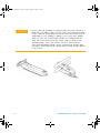
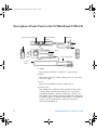
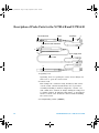
medium_standard.book Page 1 Friday, September 10, 2010 2:45 PM Agilent N2780A/B, N2781A/B, N2782A/B, and N2783A/B Current Probes User’s and Service Guide Agilent Technologies medium_standard.book Page 2 Friday, September 10, 2010 2:45 PM Notices © Agilent Technologies, Inc. 2010 Warranty No part of this manual may be reproduced in any form or by any means (including electronic storage and retrieval or translation into a foreign language) without prior agreement and written consent from Agilent Technologies, Inc. as governed by United States and international copyright laws. The material contained in this document is provided “as is,” and is subject to being changed, without notice, in future editions. Further, to the maximum extent permitted by applicable law, Agilent disclaims all warranties, either express or implied, with regard to this manual and any information contained herein, including but not limited to the implied warranties of merchantability and fitness for a particular purpose. Agilent shall not be liable for errors or for incidental or consequential damages in connection with the furnishing, use, or performance of this document or of any information contained herein. Should Agilent and the user have a separate written agreement with warranty terms covering the material in this document that conflict with these terms, the warranty terms in the separate agreement shall control. Manual Part Number N2780-97004 Edition Fifth Edition, August 2010 Printed in Malaysia Agilent Technologies, Inc. 1900 Garden of the Gods Road Colorado Springs, CO 80907 USA puter Software or Computer Software Documentation). Technology Licenses The hardware and/or software described in this document are furnished under a license and may be used or copied only in accordance with the terms of such license. Restricted Rights Legend U.S. Government Restricted Rights. Software and technical data rights granted to the federal government include only those rights customarily provided to end user customers. Agilent provides this customary commercial license in Software and technical data pursuant to FAR 12.211 (Technical Data) and 12.212 (Computer Software) and, for the Department of Defense, DFARS 252.227-7015 (Technical Data - Commercial Items) and DFARS 227.7202-3 (Rights in Commercial Com- Safety Notices CAUTION A CAUTION notice denotes a hazard. It calls attention to an operating procedure, practice, or the like that, if not correctly performed or adhered to, could result in damage to the product or loss of important data. Do not proceed beyond a CAUTION notice until the indicated conditions are fully understood and met. WARNIN G A WARNING notice denotes a hazard. It calls attention to an operating procedure, practice, or the like that, if not correctly performed or adhered to, could result in personal injury or death. Do not proceed beyond a WARNING notice until the indicated conditions are fully understood and met. N2780/81/82/83 User’s and Service Guide medium_standard.book Page 3 Friday, September 10, 2010 2:45 PM Contents 1 User’s Guide 5 Inspecting the probe 6 Accessories Supplied Notes on Safety Symbols 8 Notes on Use 7 8 9 12 Cleaning the Probe 13 Description of Probe Parts for the N2780A/B and N2781A/B 14 Description of Probe Parts for the N2782A/B and N2783A/B 16 Specifications and Characteristics 18 Specifications (Warranted) 18 Characteristics (Non-warranted) 19 General Characteristics 20 Environmental Specifications 20 Measurement Procedure 31 Preparations for Measurement 31 Demagnetization and Zero Adjustment Making the Measurement 33 2 Service Guide 31 39 Service Strategy 40 To return the current probe to Agilent Technologies for Service 40 N2780/81/82/83 User’s and Service Guide 3 medium_standard.book Page 4 Friday, September 10, 2010 2:45 PM Contents Performance Verification Testing 41 Required Test Equipment 41 Amplitude Accuracy Test 42 4 N2780/81/82/83 User’s and Service Guide medium_standard.book Page 5 Friday, September 10, 2010 2:45 PM Agilent N2780A/B, N2781A/B, N2782A/B, and N2783A/B Current Probes User’s and Service Guide 1 User’s Guide Agilent Technologies 5 medium_standard.book Page 6 Friday, September 10, 2010 2:45 PM Inspecting the probe • Inspect the shipping container for damage. Keep a damaged shipping container or cushioning material until the contents of the shipment have been checked for completeness and the instrument has been checked mechanically and electrically. • Check the accessories. Accessories supplied with the probe are listed in “Accessories Supplied” in Table 1. • If the contents are incomplete or damaged notify your Agilent Technologies Sales Office. • Inspect the probe. • If there is mechanical damage or defect, or if the probe does not operate properly or pass performance tests, notify your Agilent Technologies Sales Office. • If the shipping container is damaged, or the cushioning materials show signs of stress, notify the carrier as well as your Agilent Technologies Sales Office. Keep the shipping materials for the carrier’s inspection. The Agilent Technologies Office will arrange for repair or replacement at Agilent Technologies’ option without waiting for claim settlement. 6 N2780/81/82/83 User’s and Service Guide medium_standard.book Page 7 Friday, September 10, 2010 2:45 PM Accessories Supplied The following is a list of supplied accessories. Table 1 User’s and Service Guide 1 Carrying Case 1 N2780/81/82/83 User’s and Service Guide 7 medium_standard.book Page 8 Friday, September 10, 2010 2:45 PM Notes on Safety This device is designed to comply with IEC 61010 Safety Standards, and has been thoroughly tested for safety prior to shipment. However, mishandling during use could result in injury or death, as well as damage to the device. Be certain that you understand the instructions and precautions in the manual before use. We disclaim any responsibility for accidents or injuries not resulting directly from device defects. Symbols The following table shows the different symbols that can appear on the probe and in the manual and their meaning. ! Instruction manual symbol: the product is marked with this symbol when it is necessary for you to refer to the instruction manual in order to protect against damage to the product. Earth terminal symbol: Used to indicate a circuit common connected to grounded chassis. Hazardous voltage symbol. Do not apply around or remove from HAZARDOUS LIVE conductors. 8 N2780/81/82/83 User’s and Service Guide medium_standard.book Page 9 Friday, September 10, 2010 2:45 PM Notes on Use WARNIN G To avoid short circuits and potentially life- threatening hazards, follow these precautions. • Never attach the clamp to a circuit that operates at more than the maximum rated voltage to earth. • For safety's sake, avoid clamping around bare conductors, while clamping or measuring. • While clamping and measuring, do not touch the clamp in front of the barrier or the conductor being measured. • Be careful to avoid damaging the insulation surface while taking measurements. • Make sure that the waveform measuring equipment connected to this device's output terminal (BNC) is equipped with a protective earthing with double- insulation construction. • Do not allow the device to get wet, and do not take measurements with wet hands. This may cause an electric shock. N2780/81/82/83 User’s and Service Guide 9 medium_standard.book Page 10 Friday, September 10, 2010 2:45 PM WARNIN G • If the waveform measuring instrument being connected to the output terminal (BNC) on this device is equipped with any other measurement terminals, take the following precautions to ensure that the other instrument does not form a bridge between the probe and any hazardous live part of a part. 1 Isolate the terminal to which the probe is connected from other terminals on the measuring instrument using basic insulation conforming to the measurement category, working voltage, and pollution degree requirements of the circuit being tested. 2 If basic insulation requirements cannot be met between the terminal to which this device is connected and other terminals of the measuring instrument, make sure that the voltage input to the measurement terminal does not exceed the Separated Extra- Low Voltage Earthed (SELV- E). 3 Read and observe all warnings and precautions relating to electrical safety for the measuring instrument being connected to the probe. Refer to the following standards regarding the meanings of underlined terms. IEC 61010- 1 IEC 61010- 031 IEC 61010- 2- 032 10 N2780/81/82/83 User’s and Service Guide medium_standard.book Page 11 Friday, September 10, 2010 2:45 PM CAUTION • To avoid damage to the device, protect it from vibration or shock during transport and handling, and be especially careful to avoid dropping. • Do not store or use the device where it could be exposed to direct sunlight, high temperature, humidity, or condensation. Under such conditions, the device may be damaged and insulation may deteriorate so that it no longer meets specifications. • Before using the device the first time, verify that it operates normally to ensure that the no damage occurred during storage or shipping. If you find any damage, contact your dealer or Agilent representative. • This device is not designed to be entirely water- or dust- proof. To avoid damage, do not use it in a wet or dusty environment. • The sensor head is a precision assembly including a molded component, a ferrite core, and a Hall effect element. It may be damaged if subjected to sudden changes in ambient temperature, or mechanical strain or shock, and therefore great care should be exercised in handling it. • The matching surfaces of the sensor head are precision ground, and should be treated with care. If these surfaces are scratched, performance may be impaired. • Foreign substances such as dust on the contact surfaces of the sensor head can cause acoustic resonance and degrade measurement, so it should be cleaned by gently wiping with a soft cloth. • To avoid damaging the sensor cable and power supply cable, do not bend or pull the cables. • When the power is on, keep closed, except when clamping them onto the conductor to be measured. The facing surface of the core section can be scratched while it is open. N2780/81/82/83 User’s and Service Guide 11 medium_standard.book Page 12 Friday, September 10, 2010 2:45 PM CAUTION 12 • Do not place any unclamped conductor with an electric current of a frequency of 10 kHz or more near the sensor head. Current flowing in the conductor nearby may heat up the sensor head and cause its temperature to rise, leading to damage to the sensor. For example, when one side of a go- and- return conductor is clamped and the other side is also placed near the sensor head (as shown in the drawings below), even if the electric current is lower than the consecutive maximum current, electric currents in both sides will heat up the wires and raise the temperature, thereby causing damage to the sensor. N2780/81/82/83 User’s and Service Guide medium_standard.book Page 13 Friday, September 10, 2010 2:45 PM Cleaning the Probe If the probe requires cleaning, disconnect it from the oscilloscope and clean it with a soft cloth dampened with a mild soap and water solution. Make sure the probe is completely dry before reconnecting it to the oscilloscope. N2780/81/82/83 User’s and Service Guide 13 medium_standard.book Page 14 Friday, September 10, 2010 2:45 PM Description of Probe Parts for the N2780A/B and N2781A/B Terminator “LOCK/UNLOCK” indication Current direction indication 6 8 3 2 9 Sensor 1 4 (inside) Power supply cable 10 7 Sensor cable 1 Clamp This clamps around the conductor to be measured. 2 Slider This slider opens the clamp. Always use it to open and close the clamp 3 Lever This lock mechanism keeps the clamp closed. 4 Sensor head This clamps the conductor being measured, and carries out the actual current measurement. It is a precision assembly including a molded component, a ferrite core, and a Hall effect element. It may be damaged if subjected to sudden changes in ambient temperature, or mechanical strain of shock, and therefore great care should be exercised in handling it. 14 N2780/81/82/83 User’s and Service Guide medium_standard.book Page 15 Friday, September 10, 2010 2:45 PM 5 Barrier This structure reduces the likelihood of touching the conductor while testing, and indicates the limit of safe physical contact. Avoid touching the clamp in front of the barrier when clamping or measuring. 6 Demagnetizing switch (DEMAG) This demagnetizes the core if it has been magnetized by switching the power on and off, or by an excessive input. Always carry out demagnetizing before a measurement. The demagnetizing process takes about 3 seconds. During demagnetizing, a demagnetizing waveform is output. 7 Zero adjustment dial (ZERO ADJ) Use the zero adjustment dial to correct for the effect of a voltage offset or temperature drift on the device. When beginning a measurement, after demagnetizing, always carry out a zero adjustment. 8 Output connector N O TE Connect to the BNC input connector of the oscilloscope. The output of the current probe is terminated internally. You must select the input impedance of the oscilloscope to be 1 M in order to make accurate measurements. If the oscilloscope you are using does not have a 1 M input impedance setting you can purchase the Agilent E2697A 50 to 1 M adapter. Turn the collar until it clicks, and check that it is locked securely. 9 Power plug Connect this to the Agilent N2779A Power Supply receptacle to supply power to the sensor terminator. 10 Barrier This structure reduces the likelihood of touching the conductor while testing, and indicates the limit of safe physical contact. Avoid touching the clamp in front of the barrier when clamping or measuring. N2780/81/82/83 User’s and Service Guide 15 medium_standard.book Page 16 Friday, September 10, 2010 2:45 PM Description of Probe Parts for the N2782A/B and N2783A/B Current direction Sensor Terminator 3 “LOCK/UNLOCK” indication 1 6 7 2 8 Power supply cable Sensor cable 4 5 1 Opening lever Operating lever for opening the sensor head. Always use this lever to open the sensor head. 2 Sensor head This clamps the conductor being measured, and carries out the actual current measurement. It is a precision assembly including a molded component, a ferrite core, and a Hall effect element. It maybe damaged if subjected to sudden changes in ambient temperature, or mechanical strain or shock. Care should be exercised when handing the sensor head. 3 Demagnetizing switch (DEMAG) 16 N2780/81/82/83 User’s and Service Guide medium_standard.book Page 17 Friday, September 10, 2010 2:45 PM This demagnetizes the core if it has been magnetized by switching the power on and off, or by an excessive input. Always carry out demagnetizing before measurement. The demagnetizing process takes about one second. During demagnetizing, a demagnetizing waveform is output. 4 Zero adjustment dial (ZERO ADJ) Use the zero adjustment dial to correct for the effect of a voltage offset or temperature drift on the unit. The probe should be always be zeroed after demagnetization. 5 Coarse adjustment trimmer This adjustment should only be carried out if the probe offset is outside the range of the zero adjustment dial. 6 BNC output connector N O TE Connect to the BNC input connector of the oscilloscope. The output of the current probe is terminated internally. You must select the input impedance of the oscilloscope to be 1 M in order to make accurate measurements. If the oscilloscope you are using does not have a 1 M input impedance setting you can purchase the Agilent E2697A 50 to 1 M adapter. Turn the collar until it clicks, and check that it is locked securely. 7 Power plug Connect this to the N2779A power supply receptacle to supply power to the sensor terminator. 8 Barrier This structure reduces the likelihood of touching the conductor while testing, and indicates the limit of safe physical contact. Avoid touching the clamp in front of the barrier when clamping or measuring. N2780/81/82/83 User’s and Service Guide 17 medium_standard.book Page 18 Friday, September 10, 2010 2:45 PM Specifications and Characteristics The following specifications are guaranteed. Specifications (Warranted) N2780A/B N2781A/B Amplitude ±1.0% of reading ±500 mA ±1.0% of reading ±100 mA at 23 oC ± 3 o accuracy at 23 oC ± 3 oC (DC or 45 to 66 Hz, up to maximum continous current) 18 N2782A/B ±1.0% of reading ±10 mA at 23 oC ± 3 oC N2783A/B ±1.0% of reading ±10 mA at 23 oC ± 3 oC N2780/81/82/83 User’s and Service Guide medium_standard.book Page 19 Friday, September 10, 2010 2:45 PM Characteristics (Non-warranted) N2781A/B DC to 10 MHz (-3 dB) (Typical characteristic shown in Figure 6) Rise time 175 ns or less 35 ns or less Maximum current 500 A rms (Derating 150 A rms (Derating according to ! (continuous) rms according to frequency shown in frequency shown in Figure 2) Figure 7) Maximum peak 700 A peak 300 A peak 500 A peak; at pulse ! current value (non-continuous) width £ 30 ms Output voltage rate 0.01 V/A (100:1) 0.01 V/A (100:1) Noise (for 20 MHz band Equivalent to 25 mA Equivalent to 25 mA measuring instrument) rms or less rms or less Input impedance (Typical (Typical characteristics shown characteristics shown in Figure 3) in Figure 8) ± 2 % or less Temperature coefficient for ± 2 % or less sensitivity (within a range of 0 oC to 40 oC or 32 oF to 104 oF) Effect of external magnetic Equivalent to a Equivalent to a fields (in a DC or 60 Hz, maximum of 800 mA maximum of 150 mA 400 A/m magnetic field) Maximum rated power 7.2 VA 5.5 VA (with rated current) 20 mA 20 mA Lowest Measurable Current* (at 3%accuracy of DC current with the oscilloscope set to 1 mV/div and high resolution mode on.) Rated supply voltage DC ± 12 V ± 0.5V DC ± 12 V ± 1 V Bandwidth N2780A/B DC to 2 MHz (-3 dB) (Typical characteristic shown in Figure 1) N2782A/B DC to 50 MHz (-3 dB) (Typical characteristic shown in Figure 11) 7 ns or less 30 A rms (Derating according to frequency shown in Figure 12) 50 A peak N2783A/B DC to 100 MHz (-3 dB) (Typical characteristic shown in Figure 16) 0.1 V/A (10:1) Equivalent to 2.5 mA rms or less (Typical characteristics shown in Figure 13) ± 2 % or less 0.1 V/A (10:1) Equivalent to 2.5 mA rms or less (Typical characteristics shown in Figure 18) ± 2 % or less 3.5 ns or less 30 A rms (Derating according to frequency shown in Figure 17) 50 A peak Equivalent to a Equivalent to a maximum of 20 mA maximum of 5 mA 5.6 VA 5.3 VA 5 mA 5 mA DC ± 12 V ± 0.5 V DC ± 12 V ± 0.5V * Oscilloscope set to 1 mV/div and 20 MHz or 25 MHz bandwidth limited. N2780/81/82/83 User’s and Service Guide 19 medium_standard.book Page 20 Friday, September 10, 2010 2:45 PM General Characteristics Diameter of measurable conductors Cable lengths (Approximately) Sensor Power supply External dimensions Sensor (Approximately) Terminator Weight (Approximately) N2780A/B 20 mm (0.79”) N2781A/B 20 mm (0.79”) N2782A/B 5 mm (0.2”) N2783A/B 5 mm (0.2”) 2 m (78.7”) 1 m (39.4”) W H D 176 69 27 mm 6.93” 2.72” 1.06” 27 55 18 mm 1.06” 2.17” 0.71” 520 g (18.3 oz.) 2 m (78.7”) 1 m (39.4”) W H D 176 69 27 mm 6.93” 2.72” 1.06” 27 55 18 mm 1.06” 2.17” 0.71” 500 g (17.6 oz.) 1.5 m (59”) 1 m (39.4”) W H D 175 18 40 mm 6.89” 0.71” 1.57” 27 55 18 mm 1.06” 2.17” 0.71” 230 g (8.1 oz.) 1.5 m (59”) 1 m (39.4”) W H D 175 18 40 mm 6.89” 0.71” 1.57” 27 55 18 mm 1.06” 2.17” 0.71” 240 g (8.5 oz.) Environmental Specifications Operating temperature and humidity range Storage temperature and humidity range Bearable storage vibration Altitude Pollution degree ! Maximum rated voltage to earth Typical Transient overvoltages 20 0 oC to 40 oC (32 oF to 104 oF ) 80 %rh or less (no condensation) -10 oC to 50 oC (14 oF to 122 oF ) 80 %rh or less (no condensation) 1. Vibration 10 to 55 Hz, 30 min per axis, 1 octave/min sweep rate, Amplitude 0.3 mm 2. Vibration 55 Hz, 30 min per axis, Amplitude 0.3 mm, Vibration acceleration 17.91 m/s2 Operating up to 2,000 m (6,562 ft) Pollution degree 2 For indoor use only N2780A/B: 600 V, CAT II, 300 V CAT III (insulated conductor) N2781A/B: 600 V CAT II, 300 V CAT III (insulated conductor) N2782A/B: 300 V CAT I (insulated conductor) N2783A/B: 300 V CAT I ( insulated conductor) N2780A/B,N2781A/B: Anticipated transient overvoltage 4000 V N2782A/B,N2783A/B: Anticipated transient overvoltage 1500 V N2780/81/82/83 User’s and Service Guide medium_standard.book Page 21 Friday, September 10, 2010 2:45 PM Frequency Response Characteristic N2780A/B Amplitude [0dB=1V] Figure 1 Frequency [Hz] Figure 2 Derating according to frequency N2780A/B Maximum input current [Arms] Continuous Maximum Input Frequency [Hz] N2780/81/82/83 User’s and Service Guide 21 medium_standard.book Page 22 Friday, September 10, 2010 2:45 PM Insertion Impedance N2780A/B Insertion impedance [] Figure 3 Frequency [Hz] Deviation [%] Figure 4 DC Accuracy Characteristic N2780A/B 5 4 3 2 1 0 -1 -2 -3 -4 -5 upper limit lower limit N2780A 0.1 1 10 100 1000 DC Current [A] 22 N2780/81/82/83 User’s and Service Guide medium_standard.book Page 23 Friday, September 10, 2010 2:45 PM Deviation [%] Figure 5 AC Amplitude Accuracy Characteristic N2780A/B 5 4 3 2 1 0 -1 -2 -3 -4 -5 upper limit lower limit N2780A 0.1 1 10 100 1000 AC Current Frequency Response Characteristic N2781A/B Amplitude [0dB=1V] Figure 6 Frequency [Hz] N2780/81/82/83 User’s and Service Guide 23 medium_standard.book Page 24 Friday, September 10, 2010 2:45 PM Figure 7 Derating according to frequency N2781A/B Maximum input current [Arms] Continuous Maximum Input Frequency [Hz] Insertion Impedance N2781A/B Insertion impedance [] Figure 8 Frequency [Hz] 24 N2780/81/82/83 User’s and Service Guide medium_standard.book Page 25 Friday, September 10, 2010 2:45 PM Figure 9 DC Accuracy Characteristic N2781A/B 25 Deviation [%] 20 15 upper limit lower limit 10 N2781A 5 0 -5 0.1 1 10 100 1000 DC Current [A] Figure 10 AC Amplitude Accuracy Characteristic N2781A/B 25 Deviation [%] 20 15 upper limit 10 lower limit N2781A 5 0 -5 0.1 1 10 100 1000 AC Current N2780/81/82/83 User’s and Service Guide 25 medium_standard.book Page 26 Friday, September 10, 2010 2:45 PM Frequency Response Characteristic N2782A/B Amplitude [0dB=1V] Figure 11 Frequency [Hz] Figure 12 Derating according to frequency N2782A/B Maximum input current [Arms] Continuous Maximum Input Frequency [Hz] 26 N2780/81/82/83 User’s and Service Guide medium_standard.book Page 27 Friday, September 10, 2010 2:45 PM Insertion impedance [] Figure 13 Insertion Impedance N2782A/B Frequency [Hz] Figure 14 DC Accuracy Characteristic N2782A/B 25 Deviation [%] 20 15 upper limit 10 lower limit N2782A 5 0 -5 0.001 0.01 0.1 1 10 100 DC Current [A] N2780/81/82/83 User’s and Service Guide 27 medium_standard.book Page 28 Friday, September 10, 2010 2:45 PM Figure 15 AC Amplitude Accuracy Characteristic N2782A/B 25 Deviation [%] 20 15 upper limit lower limit 10 N2782A 5 0 -5 0.001 0.01 0.1 1 10 100 AC Current Amplitude [0dB=1V] Figure 16 Frequency Response Characteristic N2783A/B Frequency [Hz] 28 N2780/81/82/83 User’s and Service Guide medium_standard.book Page 29 Friday, September 10, 2010 2:45 PM Figure 17 Derating according to frequency N2783A/B Maximum input current [Arms] Continuous Maximum Input Frequency [Hz] Insertion impedance [] Figure 18 Insertion Impedance N2783A/B Frequency [Hz] N2780/81/82/83 User’s and Service Guide 29 medium_standard.book Page 30 Friday, September 10, 2010 2:45 PM Figure 19 DC Accuracy Characteristic N2783A/B 20 15 Deviation [%] 10 5 upper limit 0 lower limit N2783A -5 -10 -15 -20 0.001 0.01 0.1 1 10 100 DC Current [A] Figure 20 AC Amplitude Accuracy Characteristic N2783A/B 12 Deviation [%] 9 6 upper limit 3 lower limit N2783A 0 -3 -6 0.001 0.01 0.1 1 10 100 AC Current 30 N2780/81/82/83 User’s and Service Guide medium_standard.book Page 31 Friday, September 10, 2010 2:45 PM Measurement Procedure Preparations for Measurement CAUTION 1 Have the N2779A power supply and oscilloscope ready for waveform measurement ready. Before turning on the power, make sure that the voltage of the power supply being used matches the supply voltage indicated on the rear panel of the N2779A. 2 Turn the power switch off and connect the power cord. 3 Connect the power plug of the current probe to the power receptacle of the N2779A. 4 Turn the N2779A power switch on, and check that the front panel power indicator lights. Demagnetization and Zero Adjustment N O TE The output of this unit is terminated internally. Use a high impedance input to the measuring instrument. Accurate measurements are not possible when the input impedance of the oscilloscope is set to 50 . Besure to set the input impedance to 1 M before making measurements. If the oscilloscope input impedance cannot be set to 1 M then the Agilent E2697A impedance adaptor can be purchased. 1 With the oscilloscope input at ground, adjust the trace to the zero position. 2 Set the input coupling of the oscilloscope to DC. N2780/81/82/83 User’s and Service Guide 31 medium_standard.book Page 32 Friday, September 10, 2010 2:45 PM 3 Connect the output connector of the current probe to the input connector of the oscilloscope. Turn the collar until it clicks, and check that it is locked securely. CAUTION • When disconnecting the output connector, be sure to release the lock, then pull the connector. Forcibly pulling the connector without releasing the lock, or pulling on the cable will result in damage to the terminator. • Do not demagnetize while the conductor being measured is clamped. This could damage the components of the circuit being measured. • Check that the conductor being measured is not clamped when supplying power to the current probe for the same reason. Demagnetized waveforms are generated when switching on the supply. 4 Without clamping the conductor to be measured, press the opening lever until the "UNLOCK" indication disappears, and check that the sensor head is properly closed. 5 Press the demagnetizing switch (DEMAG) on the terminator. 6 Turn the zero adjustment dial on the terminator to adjust the trace to the zero position. 7 If zero adjustment is not possible in step 6, turn the coarse adjustment trimmer to bring the trace within the range of adjustment by the zero adjustment dial. 32 N2780/81/82/83 User’s and Service Guide medium_standard.book Page 33 Friday, September 10, 2010 2:45 PM Making the Measurement 1 Check that the system is safe and that the preparations described in the preceding section have been carried out. 2 Pull the sensor opening lever with the sensor head opens. 3 Align the sensor so that the current direction indication corresponds to the direction of current flow through the conductor to be measured. Also, align the clamp so that the conductor is in the center of the sensor aperture. 4 Press the opening lever on the sensor head until the "UNLOCK" indication disappears. Also check that the opening lever is firmly locked and the sensor head securely closed. 5 Before making current measurements, the oscilloscope must be set up as follows. The N2780A/B and N2781A/B oscilloscope setup. Input Impedance Attenuation Ratio Units 1 M 100:1 Amperes The N2782A/B and N2783A/B oscilloscope setup. Input Impedance Attenuation Ratio Units N2780/81/82/83 User’s and Service Guide 1 M 10:1 Amperes 33 medium_standard.book Page 34 Friday, September 10, 2010 2:45 PM CAUTION • The maximum continuous input range is based on heat that is internally generated during measurement. Never input current in excess of this level. Exceeding the rated level may result in damage to the probe. • The maximum continuous input range varies according to the frequency of the current being measured. See the figures in “Specifications and Standards Applying” • If excess current is input, generated heat activates a built- in safety function that blocks normal output. If this happens, remove the input immediately (remove the sensor from the conductor being measured or reduce the input current to zero). Wait until the sensor has had sufficient time to cool before resuming operation. • Even if the input current does not exceed the rated continuous maximum, continuous input for an extended period of time may result in activation of the safety circuit to prevent damage resulting from heating of the sensor. • At high ambient temperatures, the built- in safety circuit may activate at current input levels below the rated continuous maximum. • Continuous input of current exceeding the rated maximum or repeated activation of the safety function may result in damage to the unit. • The probe is rated for maximum input under two conditions in addition to the input maximums shown in the “Specifications and Characteristics" on page 18. These are (1) 30 Apeak for noncontinuous input and (2) 50 Apeak for pulse widths 10 µs. (1) indicates an upper waveform response limit of 30 Apeak. Use the sensor at RMS current input levels that are within the rated continuous maximums. (2) indicates the upper response limit for a single input pulse. 34 N2780/81/82/83 User’s and Service Guide medium_standard.book Page 35 Friday, September 10, 2010 2:45 PM CAUTION • When opening the sensor head of the probe, be sure to operate with the opening lever. If an upper core is forced to open when the sensor head is locked, the open- close mechanism can be damaged. N2780/81/82/83 User’s and Service Guide 35 medium_standard.book Page 36 Friday, September 10, 2010 2:45 PM N O TE • The output of this unit is terminated internally. Use an oscilloscope with an input impedance of at least 1 M or use the Agilent E2697A impedance adapter. • Immediately after powering on the probe, the probe may be subject to an appreciable offset drift due to the effect of self- heating. To counteract this, allow the probe to warm up for about 30 minutes before carrying out measurement. • When performing continuous measurements, it is necessary to be aware that the offset voltage drifts, depending on factors such as the ambient temperature. • Under certain circumstances, oscillation may occur if the probe is connected to the N2779A power supply while the power supply is on. This does not indicate a malfunction. Oscillation can be stopped and operation restored to normal by opening and closing the sensor head. • Depending on the measured current frequency, some sound maybe produced by resonance, but has no effect on measurements. • The reading may be affected by the position within the clamp aperture of the conductor being measured. The conductor should be in the center of the clamp aperture. • When carrying out a measurement, press the opening lever until the “UNLOCK” indication disappears and check that the sensor head is properly closed. If the sensor head is not properly closed, an accurate measurement is not possible. • Accurate measurement may be impossible in locations subject to strong external magnetic fields, such as transformers and high- current conductors, or in locations subject to strong external electric fields, such as radio transmission equipment. . 36 N2780/81/82/83 User’s and Service Guide medium_standard.book Page 37 Friday, September 10, 2010 2:45 PM N O TE • At high frequencies, common mode noise may affect measurements taken on the high voltage side of circuits. If this occurs, reduce the frequency range of the waveform measuring instrument or clamp onto the low- voltage side of the circuit, as appropriate. High X Power Source Load Low High X Power Source Load Low N2780/81/82/83 User’s and Service Guide 37 medium_standard.book Page 38 Friday, September 10, 2010 2:45 PM 38 N2780/81/82/83 User’s and Service Guide medium_standard.book Page 39 Friday, September 10, 2010 2:45 PM Agilent N2780A/B, N2781A/B, N2782A/B, and N2783A/B Current Probes User’s and Service Guide 2 Service Guide Agilent Technologies 39 medium_standard.book Page 40 Friday, September 10, 2010 2:45 PM Service Strategy To return the probe to optimum performance requires factory repair. If the probe is under warranty, normal warranty services apply. To return the current probe to Agilent Technologies for Service In the U.S., call (800) 829- 4444 for further details and the location of your nearest Agilent Technologies service center. Outside the U.S., call your nearest Agilent sales office and ask them how to contact the nearest Agilent service center. 1 Write the following information on a tag and attach it to the current probe. • Name and address of the owner • Current probe model number • Description of service required or failure indications 2 Retain all accessories. 3 Return the current probe in its original shipping materials or pack the power supply in foam or other shock- absorbing material and place it in a strong shipping container. If the original shipping materials are not available, place 3 to 4 inches of shock- absorbing material around the instrument and place it in a box that does not allow movement during shipping. 4 Seal the shipping container securely. 5 Mark the shipping container as FRAGILE. In all correspondence, refer to the current probe by model number and full serial number. 40 N2780/81/82/83 User’s and Service Guide medium_standard.book Page 41 Friday, September 10, 2010 2:45 PM Performance Verification Testing Required Test Equipment Description Probe Power Supply Digital Multimeter (DMM) Signal Generator Adapter Test Coil Critical Specifications Recommended No substitute Agilent N2779A AC/DC voltage and current measurement Agilent 34401A accuracy better than ±0.1% of reading at 10 mA Input resistance in AC/DC voltage mode ¡ 1 M DC to 66 Hz sine waves able to generate more Agilent 6813B than 10 A in the test coil (e.g. an inductive load). BNC (f) to dual stacking banana plug Pomona 1269 5, 50, or 77 turns 16-AWG 155C CU round (See coil construction instructions that follow.) magnetic wire (NEMA MW 35-C); Red enamel (transformer wire) Test Coil Construction for the N2780A/B Construct a 77- turn coil with a diameter of about 4 inches (10 cm) using transformer wire. 77 turns Test Coil Construction for the N2781A/B Construct a 50- turn coil with a diameter of about 4 inches (10 cm) using transformer wire. 50 turns N2780/81/82/83 User’s and Service Guide 41 medium_standard.book Page 42 Friday, September 10, 2010 2:45 PM Test Coil Construction for the N2782A/B and N2783A/B Construct a 5- turn coil with a diameter of about 4 inches (10 cm) using transformer wire. 5 turns Amplitude Accuracy Test The following procedure measures the accuracy of the current probe. 1 Connect the equipment as shown below. Allow all instruments 30 minutes for warm up before starting the 42 N2780/81/82/83 User’s and Service Guide medium_standard.book Page 43 Friday, September 10, 2010 2:45 PM test procedure. While the test system is warming up, clean the magnetic contacts on the probe jaw. DMM Adapter Probe Power Supply Signal Generator ! SENSE 01 01 COM COM Current Probe Test Coil 2 Press the DEMAG button on the probe terminator. 3 Configure the DMM to measure AC Volts. 4 Clamp the probe around the coil and ensure that the probe is as perpendicular as possible to the coils of wire. 5 Set up the signal generator as follows: • Wave shape: Sine • Frequency: 50 Hz N2780/81/82/83 User’s and Service Guide 43 medium_standard.book Page 44 Friday, September 10, 2010 2:45 PM • Amplitude: N2780A/B 6.5 A rms N2781A/B 3 A rms N2782A/B 6 A rms N2783A/B 6 A rms • Offset: 0.0 Vdc 6 Measure the voltage output of the probe on the DMM and record this value in Table 2. 7 Do the current calculation by multiplying the DMM Voltage by the value in the Multiplier column of Table 2 and record the answer in the Calculated Amperes column for the probe you are measuring. 8 Compare this value to the Passing Range values to determine if the probe passes the test. Table 2 Model Number N2780A/B N2781A/B N2782A/B N2783A/B 44 DMM Voltage Multiplier 100 100 10 10 Calculated Amperes Passing Range 505.5 A to 494.5 A 151.6 A to 148.4 A 30.31 A to 29.69 A 30.31 A to 29.69 A N2780/81/82/83 User’s and Service Guide medium_standard.book Page 45 Friday, September 10, 2010 2:45 PM medium_standard.book Page 46 Friday, September 10, 2010 2:45 PM www.agilent.com Agilent Technologies, Inc. 2010 Printed in Malaysia August 2010 Fifth Edition, August 2010 *N2780-97004* N2780-97004 Agilent Technologies