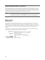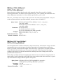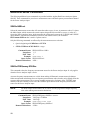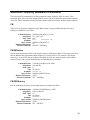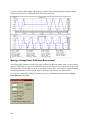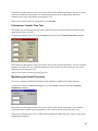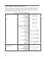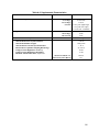
1
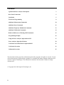
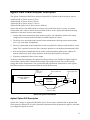
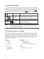
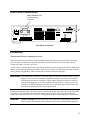
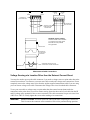
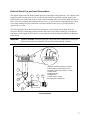
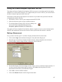
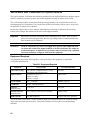
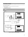
ADDENDUM to the Agilent 6811B, 6812B, and 6813B User’s Guide and Programming Guide for the Dual Power Analyzer Option 020/022 Agilent P/N 5964-8134 Microfiche No 5964-8135 Printed in U.S.A. May, 2000 Contents Agilent Dual Power Analyzer Description 3 Rear Panel Connections 5 Installation 5 Front Panel Programming 8 Additional Measurement Commands 10 Additional Sense Commands 12 Additional Frequency Modulation Commands 13 Additional Calibration Commands 14 Behavior Differences of Existing SCPI Commands 15 Programming Example 16 Using the Power Analyzer Input with the GUI 17 Power Analyzer Input Specifications 20 Verification and Calibration for Option 020/022 22 Verification Procedure 23 Calibration Procedure 25 This document contains proprietary information protected by copyright. All rights are reserved. No part of this document may be photocopied, reproduced, or translated into another language without the prior consent of Agilent Technologies. The information contained in this document is subject to change without notice. Copyright 1999, 2000 Agilent Technologies, Inc. 2 Agilent Dual Power Analyzer Description The Agilent Technologies Dual Power Analyzer Option 020 is available on the following ac sources: Agilent 6811B AC Power Source (375VA) Agilent 6812B AC Power Source (750VA) Agilent 6813B AC Power Source (1750VA) Agilent 6813B Option 019 AC Power Source (2000VA) Option 020 consists of an additional Power Analyzer input on the back of the ac source, an external current shunt, and a cable to connect the current shunt to the ac source. Option 020 adds the following capabilities to the above listed ac source models: • Voltage and current measurement inputs on the rear panel, with capabilities similar to the output voltage and current measurements available in standard Agilent ac sources. • The ability to use any shunt for the external current measurement, allowing current measurements over a very wide range of magnitudes. • Precisely synchronized measurements between the rear panel Power Analyzer input and the ac source output. This is possible because the Power Analyzer input has its own dedicated measurement buffer. • New measurement commands that may be used in evaluating uninterruptible power supplies (To measure transfer time, peak voltage, and phase locked loop performance for example). • Frequency modulation of the ac source output. As shown in the following figure, the Agilent Dual Power Analyzer also includes an Agilent supplied current shunt, which must be connected to the output of the equipment under test to make accurate voltage and current measurements. The specifications and supplemental characteristics of the Agilent Dual Power Analyzer are documented toward the end of this document. Agilent AC SOURCE (side view) ac in Agilent supplied cable Equipment Under Test output Agilent supplied shunt Line Load Shunt Load Power Analyzer Input (V & I sense) AC Source output ac line cables (customer supplied) Option 020 Typical Connections Agilent Option 022 Description Option 022 is simply an Agilent 6813B Option 019 AC Power Source combined with an Agilent Dual Power Analyzer Option 020. All of the Option 020 information in this document also applies to units that are configured as Option 022 units. 3 Front Panel Menus - Additions The Power Analyzer input uses the same front panel menu commands that are used to measure the Main Output of the ac source. These are documented in the ac source User’s Guide. The following menu commands have been added to let you access the Power Analyzer input, control the output frequency modulation, and calibrate the Power Analyzer input. In most cases you will need to press the ô Function key multiple times to access the menu item. Press the ° Entry key to access the parameter. φ1 Phase Select φ2 Input ô ô ô ô Shift Cal Freq NOTE: ô ô ô 115V 60 Hz Displays the Main Output measurement when φ1 is selected 120V 60 Hz Displays the Power Analyzer measurement when φ2 is selected FM OFF Enable or disable output frequency modulation (OFF or ON) FM:FREQ 50 Specifies the modulating frequency of the output FM:DEV 10 Specifies the peak deviation of the output frequency modulation FREQ:SRC VOLT Specifies the frequency input source (VOLT or CURR) CAL:CURR: EXT Begin external current calibration CAL:VOLT: EXT Begin external voltage calibration SHUNT Enter a value for the external shunt in ohms With no signal connected to the Power Analyzer input, the φ2 front panel display may return a very high frequency value. This is normal, since there is no external frequency for the measurement circuit to detect. SCPI Programming Commands - Additions The Power Analyzer input uses the same measurement commands that are used to measure the Main Output of the ac source. These are documented in the ac source User’s Guide. The following SCPI commands have been added to let you access the Power Analyzer input, control the output frequency modulation, and calibrate the Power Analyzer input. Additional measurement functions let you measure transfer time, peak voltage, and phase locked loop performance when evaluating devices such as uninterruptible power supplies. CALibrate :CURRent :EXTernal :VOLTage :EXTernal :SHUNt MEASure | FETCh :VOLTage :RANKed? <percentile> :TVOLt? <level><occurrence> :ABSolute? <level><start_time><min_pulse_width> FM SENSe :NSELect 1 | 2 :FREQuency:SOURce VOLT | CURR :STATe <bool> :DEViation <value> :FREQuency <value> 4 Rear Panel Connections Power Analyzer input. Connector plug is removable. LO HI I SENSE HP-IB LO HI ..... RS 232 V SENSE _ FLT INH + - + _ .... WARNING CAUTION TRIGGER IN 1 OPTIONS LINE RATING OUT 1 WARNING SENSE COM COM _ _ O1 _ _ O1 L1 _ _ 300 VAC MAX TO L 2( N ) Rear Panel, Overall View Installation Turn the unit off before connecting any wires. The Power Analyzer input to the ac source has both voltage and current sense inputs. Each sense input has a HI and a LO connection. The center pin of the connector is not used. The maximum isolation voltage to ground is 300 Vac (±425 Vdc). Use the 1-meter, Agilent supplied cable and connect the Power Analyzer input to the external shunt. Note that the cable connectors are keyed so that the cable will only fit one way. Disconnect the cable from the unit by pulling it straight back. Cable connections are shown in the following figure. IMPORTANT: You should always connect the V SENSE inputs for the Power Analyzer input to operate properly, even if you are not making voltage measurements. This is because frequency measurements are made by sensing the voltage signal, and many of the power analyzer measurements depend on an accurate frequency measurement. If a voltage signal is not available, use SENSe:FREQuency:SOURce (or its front panel equivalent) to select and measure the frequency from the current signal instead. If the Agilent supplied cable is too short, you may open the cable ends and replace the wiring in the cable with longer wires. Install the new cable in the same way as the original cable. The cable connectors accepts wire sizes from AWG 22 to AWG 12. Firmly tighten the screws when making wire connections. WARNING: SAFETY HAZARD You must replace the cable hoods after completing all connections. This is because the connector screw terminals will be at line potential during operation. 5 LO HI I SENSE LO HI V SENSE HI LO V SENSE I SENSE HI LO CONNECTOR (AC SOURCE END) HOODS PLACED OVER WIRES AND CONNECTORS CONNECTOR (SHUNT END) WARNING, SAFETY HAZARD: Connector hoods must be installed on connectors. Connector screw terminals are at line potential during operation. RELEASE TAB CONNECTOR HALVES SNAP TOGETHER RELEASE TAB WIRES MUST BE INSTALLED IN STRAIN RELIEF INSIDE CONNECTOR Measurement Cable Connections Voltage Sensing at a Location Other than the External Current Shunt You may also need to open up the cable connector if you need to voltage sense at a point other than at the external current shunt. You must use your own sense cable to make the voltage sense connections. Please completely remove the voltage sense wires from the Agilent supplied measurement cable if you are using your own remote voltage sense cable. Disconnect the voltage sense wires from both cable connectors. To use your own cable to voltage sense at a point other than the external current shunt, make the connections at the point where you will be remote sensing. Insert the other end of your cable into the HI and LO voltage sense terminals of the ac source connector. The cable connectors accepts wire sizes from AWG 22 to AWG 12. Firmly tighten the screws when making wire connections. WARNING: 6 SAFETY HAZARD You must replace the cable hoods after completing all connections. This is because the connector screw terminals will be at line potential during operation. External Shunt Line and Load Connections The Agilent supplied current shunt has both input (line) and output (load) connectors. The customer must supply the cables to connect the ac lines to and from the external current shunt. Agilent supplies one hooded cable cover for the input of the ac source and two hooded cable covers for the shunt. All three of these covers are assembled and installed in the same way. It is the customer’s responsibility to use these covers when making line cable connections. Note that a different cable cover is provided for the ac output of the ac source. The following figure shows the Load and Line connectors on the external current shunt. Note the location of the line, neutral and ground connectors and connect your cables accordingly. Note that the connections on the output of the ac source are not in the same order on the barrier block as on the shunt barrier block. WARNING: SAFETY HAZARD You must replace the cable hoods after completing all connections. This is because the screw terminals will be at line potential during operation. N L 1 2 6 3 7 8 1. NEUTRAL CONNECTION (BLUE OR WHITE) 2. LINE CONNECTION (BROWN OR BLACK) 3. GROUND CONNECTION (GRN/YEL OR GRN) 4. POWER CORD 5. CONNECTOR NUT 6. RUBBER BOOT 7. POWER SAFETY COVER 8. STRAIN RELIEF CONNECTOR 4 5 Line Connections 7 Check the External Current Shunt Setting After you have completed your cable connections, you can turn on and check out the ac source as described in the Turn-On Checkout chapter in the ac source User’s Guide. One additional step in checking out a unit with Option 020/022 installed, is to make sure that the correct shunt value has been entered in the unit. To check the shunt value setting, proceed as follows: Action Display 1. Turn on the ac source and wait for the unit to finish its internal selftest. 2. Press Shift Calibration and scroll to the SHUNT command. 3. Check to see if the resistance value on the display matches the value written on the outside of the external current shunt. SHUNT 0.01 If it matches, press Meter to return to meter mode. You are done. If it does not match, you must enter the correct value. Proceed as follows: 4. Press Shift Calibration, scroll to CAL ON and press Enter. If necessary, enter the calibration password from Entry keypad and press Enter. If the password is correct the Cal annunciator will come on. CAL ON 0.0 5. Press Shift Calibration and scroll to the SHUNT command. Enter the shunt value written on the outside of the external current shunt exactly as it is written on the label. Then press Enter. SHUNT 0.01 6. Press Shift Calibration, scroll to CAL SAVE, and press Enter. CAL:SAVE 7. Press Shift Calibration, select CAL OFF, and press Enter to exit Calibration. CAL OFF NOTE: The shunt value that you enter applies only to the Power Analyzer input and has no effect on ac source output measurements. Therefore, ignore the φ1 and φ2 annunciators while entering the shunt value. Front Panel Programming Setting the Output Frequency Modulation To set the output frequency modulation: Action Display 1. On the Function keypad, press Frequency. Then scroll to the FM:FREQ command to enter a modulating frequency. Use the numeric keypad to enter a modulating value and press Enter. FM:FREQ 1 2. To set the peak frequency deviation of the output frequency modulation, press Frequency. Then scroll to the FM:DEV command to enter a frequency deviation. Use the numeric keypad to enter a value and press Enter. FM:DEV The deviation frequency must be less than the programmed output frequency by at least 0.001 Hz. Otherwise, it will result in Error 613. 3. 8 To enable frequency modulation, press Frequency, scroll to FM OFF, select the ON parameter and press Enter. FM ON 10 Using the Front Panel Display with the Power Analyzer Input To select the measurement source: Action Display Press Meter to return the display to Meter mode. Press Phase Select at any time to toggle between the Main Output and the Power Analyzer input. The left-most digit of the front panel display will indicate either "φ1" for the Main Output, or "φ2" for the Power Analyzer input. If the φ2 front panel display returns a very high frequency value, it usually means that there is no signal connected to the Power Analyzer input. φ2 115V 60Hz Note that the Phase Select key also selects the measurement source to which the current range setting applies. The current range command is located in the Input menu. Making Power Analyzer Input Measurements All measurements are based on acquiring and subsequently processing waveform information. Waveform information is acquired either from the ac source output or from the Power Analyzer input. When the ac source is on, it continually takes measurements and updates the front panel meter from whichever measurement source is active. The Meter key accesses the measurement functions from the front panel. This menu applies to both the ac source output and the Power Analyzer input. NOTE: The Shift Harmonic functions also apply to the Power Analyzer input. If the display indicates OVLD, the measurement capability of the unit has been exceeded. Use the Meter menu for making Power Analyzer input measurements: Action Display 1. Press Phase Select to toggle to the Power Analyzer input. A φ2 will appear on the display when the Power Analyzer input is selected. φ2 2. Press Meter and q repeatedly to access the following measurement functions: ♦ rms voltage and frequency (the default) ♦ rms voltage and rms current ♦ rms current and frequency (the default) ♦ rms voltage and power ♦ current crest factor ♦ peak current, repetitive ♦ peak current, non-repetitive ♦ apparent power ♦ reactive power ♦ power factor φ2 φ2 φ2 φ2 φ2 φ2 φ2 φ2 φ2 φ2 115V 3.04A <reading>V <reading>Hz <reading>V <reading>A <reading>A <reading>Hz <reading>V <reading>W <reading> CREST F <reading>A PK REP <reading>A PK NR <reading> VA <reading> VAR <reading> PFACTOR The ac source uses the output frequency value when calculating many of the output measurements. For ac source output measurements, the ac source uses the programmed output frequency value. For the Power Analyzer input , the ac source uses the frequency measured at the V SENSE input channel. This is the default setting. You can also select the I SENSE input channel as the frequency measurement source. Use the Input menu for selecting the frequency source: Action Display If a voltage signal is not available to measure the output frequency, you must select the current measurement as the frequency source. Press Input, scroll to FREQ:SRC VOLT, select the CURR parameter and press Enter. FREQ:SRC CURR 9 Additional Measurement Commands The following additional measurement commands are provided with the Agilent Dual Power Analyzer Option 020/022. These measurement commands are optimized for use in specific applications such as evaluating uninterruptible power supplies. In this application the new commands can be used to measure transfer time, peak voltage, and phase locked loop performance of the UPS. NOTE: All MEASure and FETCh commands apply to both the Main Output and the Power Analyzer input. This includes commands documented in the ac source User’s Guide and those described in this section. See SENS:NSEL to select a power analyzer input. MEASure:TVOLt? FETCh:TVOLt? Returns the time at which the measured voltage crosses a user-specified voltage level. The sign and magnitude of occurrence define the event to be reported. For example, if occurrence is -3, the return value is the third time at which the voltage crosses the level in the negative-going direction. If occurrence is 4, the return value is the fourth time at which the voltage crosses the level in the positive-going direction. The return value is with respect to the start of the measurement buffer. If no point on the waveform satisfies the specified conditions, the return value is 9.91000E+37. Query Syntax MEASure:[SCALar]:TVOLt? <level>, <occurrence> FETCh:[SCALar]:TVOLt? <level>, <occurrence> Parameters −1E6 to 1E6 (for level) −4096 to +4096, but not 0 (for occurrence) FETC:TVOL? 10, -1 Examples MEAS:TVOL? 50, 3 Returned Parameters <NR3> Related Commands MEAS:TVOL:ABS? 10 MEASure:TVOLt:ABSolute? FETCh:TVOLt:ABSolute? Returns the time at which the absolute value of the measured voltage first exceeds level, with the following qualifications: The behavior of the signal before start_ time is ignored, and the absolute value of the voltage must remain above level for at least the specified min_ pulse_ width. Both start_ time and the return value are with respect to the start of the measurement buffer. If no point on the waveform satisfies the specified conditions, the return value is 9.91000E+37. Query Syntax MEASure:[SCALar]:TVOLt:ABSolute? <level>, <start_time>, <min_pulse_width> FETCh:[SCALar]:TVOLt:ABSolute? <level>, <start_time>, <min_pulse_width> Parameters 0 to 1E6 (for level) 0 to 1E6 (for start time in seconds) 0 to 1E6 (for minimum pulse width in seconds) Examples MEAS:TVOL:ABS? 50, 0, 0.001 FETC:TVOL:ABS? 100, 0.005, 0 Returned Parameters <NR3> Related Commands MEAS:TVOL? MEASure:VOLTage:RANKed? FETCh:VOLTage:RANKed? Scans through the buffer of 4096 instantaneous voltage measurements, and returns the voltage value that corresponds to the percentile rank given. Specifying a percentile of 0 returns the lowest value in the buffer. A percentile of 100 returns the highest value in the buffer. A percentile of 50 returns the median value of the buffer. Stated another way, if you specify a percentile of 60, 60 percent of the voltage readings in the buffer are less that the returned value, and 40 percent of the readings in the buffer are greater than the returned value. If the voltage waveform consists of rectangular pulses that have narrow overshoots, using percentiles of approximately 5 and 95 (depending on the width of the pulses and the width of the overshoots) is a good way to determine the voltages at the flat portions of the pulses. Query Syntax MEASure:[SCALar]:VOLTage:RANKed? <percentile> FETCh:[SCALar]:VOLTage:RANKed? <percentile> Parameters 0 to 100 Examples MEAS:VOLT:RANK? 50 Returned Parameters <NR3> 11 Additional Sense Commands The following additional sense commands are provided with the Agilent Dual Power Analyzer Option 020/022. These commands let you select a measurement source and the frequency measurement channel for the Power Analyzer input. SENSe:NSELect Selects the measurement source that will return data when a query is sent. A parameter value of 1 selects the Main Output, which measures the actual output voltage and current of the ac source. A value of 2 selects the Power Analyzer input, which measures the voltage and current at the V SENSE and I SENSE input channels. Note that this command is similar to, but not the same as, the command INSTrument:NSELect that is used in 3-phase sources. Only the following commands are affected by the measurement source selection: • Queries beginning with MEASure or FETCh • SENSe:CURRent:ACDC:RANGe <range> Command Syntax Parameters *RST Value Examples Query Syntax Returned Parameters SENSe:NSELect <NR1> 1|2 1 SENS:NSEL 2 SENSe:NSELect? <NR1> SENSe:FREQuency:SOURce This command selects the frequency measurement source for the Power Analyzer input. It only applies when the Power Analyzer input is active. Accurate frequency measurements are critical when making all Harmonic measurement calculations. Other measurement calculations also use frequency measurement values, but they only slightly affect the accuracy of the measurement. The ac source normally measures the frequency at the V SENSE input channel. With this comand you can select the I SENSE input channel as the frequency measurement source for the Power Analyzer input. NOTE: For Main Output measurements, the ac source uses the programmed output frequency value when making measurement calculations. Command Syntax Parameters *RST Value Examples Query Syntax Returned Parameters 12 SENSe:FREQuency:SOURce <source> VOLTage | CURRent VOLTage SENS:FREQ:SOUR CURR SENSe:FREQuency:SOURce? <CRD> Additional Frequency Modulation Commands The following SCPI commands are used to program the output frequency of the ac source. These commands apply only to the Main Output of the ac source and do not affect the measurement capability of the unit. These commands are only provided with the Agilent Dual Power Analyzer Option 020/022. FM Turns off or on frequency modulation of the Main Output. Frequency modulation operates only if FREQuency:MODE is set to FIXed. Command Syntax Parameters *RST Value Examples Query Syntax Returned Parameters Related Commands [SOURce:]FM[:STATe] <bool> 0 | 1 | OFF | ON OFF FM 1 FM:STATE ON [SOURce:]FM[:STATe]? 0|1 FM:DEV FM:FREQ FM:DEViation Sets the peak frequency deviation of the output frequency modulation in Hertz. The frequency deviation must be less than the programmed output frequency by at least 0.001 Hz. For example, if the output frequency is set to 60 Hz, and you program a deviation of 10 Hz, the output frequency will modulate between 50 and 70 Hz at a rate determined by the FM:FREQuency command. Command Syntax Parameters *RST Value Unit Examples Query Syntax Returned Parameters Related Commands [SOURce:]FM:DEViation <NRf> 0 to 1000 Hz 0 Hz (Hertz) FM:DEV 10 [SOURce:]FM:DEViation? <NR3> FM FM:FREQ FM:FREQuency Sets the modulating frequency of the output frequency modulation in Hertz. Command Syntax Parameters *RST Value Unit Examples Query Syntax Returned Parameters Related Commands [SOURce:]FM:FREQuency <NRf> 0.001 to 1000 Hz 0.1 Hz (Hertz) FM:FREQ 1 [SOURce:]FM:FREQuency? <NR3> FM FM:DEV 13 Additional Calibration Commands The following SCPI commands are used to calibrate the Power Analyzer input and external current shunt: CALibrate:VOLTage:EXTernal Initiates calibration of the external voltage measurement. Command Syntax CALibrate:VOLTage:EXTernal Parameters None Examples CAL:VOLT:EXT CALibrate:CURRent:EXTernal Initiates calibration of the external current measurement. Command Syntax CALibrate:CURRent:EXTernal Parameters None Examples CAL:CURR:EXT CALibrate:SHUNt Lets you enter the external current shunt value (in ohms). The external current shunt is used for external current measurement. The programming range is 1E-6 to 1E6. This parameter is nonvolatile, so there is no *RST value. As with other CAL commands, calibration must first be enabled with CAL:STATe, and the value must be made permanent with CAL:SAVE. Command Syntax CALibrate:SHUNt <value> Parameters Current shunt value in ohms Examples CAL:SHUN .01 14 Behavior Differences of Existing SCPI Commands This section documents the behavior differences of existing SCPI commands when the Power Analyzer input is selected or is active. MEASure | FETCh All standard ac source MEASure or FETCh functions are available for the Main Output of the ac source as well as the Power Analyzer input. The SENSe:NSELect command selects the measurement source that will return data. MEASure:FREQuency? When the Power Analyzer input is selected as the measurement source, this command returns the actual frequency measured at the V SENSE input channel. When the Main Output of the ac source is selected as the measurement source, this command returns the programmed output frequency. NOTE: With no signal connected to the Power Analyzer input, this command may return a very high frequency value. This is normal, since there is no external frequency for the measurement circuit to detect. SENSe:CURRent:ACDC:RANGe <value> Sets the current measurement range of the selected measurement source (see SENSe:NSELect). Normally when using the Main Output as the measurement source, you would put in a value and the ac source will automatically select the current range. If you are using the Power Analyzer input with an external current shunt as the measurement source, the crossover value of the current ranges can be determined with the following formula: Crossover_value = 0.05713/shunt_resistance. Values greater than the crossover value select the high current range. Alternatively, you can simply program MIN or MAX to select the low or high current range. TRIGger:ACQuire and other measurement trigger commands SENSe:SWEep:TINTerval and other measurement timebase commands SENSe:WINDow These commands always apply to both measurement sources, regardless of which source is selected. *IDN? Returns the same response as a standard ac source, except for the firmware revision number. *OPT? Returns 20, except that the Agilent 6813B 2000 VA model returns 22. SYSTem:CONFigure <NORMal | IEC > All Option 020 capabilities are only available in NORMal mode. SYSTem:LANGuage <SCPI | E9012> All Option 020 capabilities are only available in SCPI mode. 15 Programming Example UPS Transfer Time Measurement The following programming example illustrates how to use the ac source with the Dual Power Analyzer Option 020/022 to measure transfer time on a UPS. Transfer time is defined as the time it takes a UPS to go from online-operation to battery-backup operation when the ac line fails. This example starts with the ac source output voltage (UPS input voltage) at 120 Vac. The UPS output voltage is connected to a load and to the Power Analyzer input. The ac source output turns on at 120 Vac, then does a 50 ms dropout to 0 volts. Both the dropout and measurements are triggered at the same time. The FETC:TVOLT:ABS? command is then used to return the transfer time, here defined as the time between the start of the dropout and the time when the absolute value of the UPS output voltage exceeds 50 volts for at least 0.001 seconds. 100 110 120 130 140 150 160 170 180 190 200 210 220 230 240 250 260 270 280 290 300 310 320 330 340 350 360 370 380 390 400 410 420 430 440 450 16 ASSIGN ! ! OUTPUT OUTPUT OUTPUT WAIT 2 ! ! OUTPUT OUTPUT OUTPUT ! ! OUTPUT OUTPUT OUTPUT @Ps TO 705 ! AC SOURCE IS AT ADDRESS 5, INTERFACE 700 @Ps;"*RST" ! BEGIN FROM A KNOWN STARTING POINT WITH RESET @Ps;"VOLT 120" ! SET INITIAL INPUT VOLTAGE FOR UPS TO 120 VAC @Ps;"OUTP ON" ! TURNS AC SOURCE OUTPUT ON AT 120 VAC ! MAKE SURE UPS OUTPUT HAS TIME TO SETTLE @Ps;"VOLT:MODE PULS" ! SET UP PULSE MODE FOR AC SOURCE OUTPUT @Ps;"PULS:WIDT 0.05" ! SET PULSE WIDTH TO 50 MILLISECONDS @Ps;"VOLT:TRIG 0" ! SET PULSED (TRIGGERED) VALUE TO 0 VOLTS @Ps;"TRIG:SYNC:SOUR PHAS" ! SETS DROPOUT SYNCHRONIZATION TO PHASE @Ps;"TRIG:SYNC:PHAS 90" ! SETS DROPOUT START PHASE TO 90 DEGREES @Ps;"TRIG:SOUR BUS" ! SETS DROPOUT TRIGGER AND MEASUREMENT ! TRIGGER SOURCE TO BUS TRIGGER ! ! OUTPUT @Ps;"OUTP:TTLT:SOUR BOT" OUTPUT @Ps;"OUTP:TTLT:STAT ON" OUTPUT @Ps;"TRIG:ACQ:SOUR TTLT" ! ! ! ! ! SETS SIGNAL TRIGGER SOURCE TO BEGINNING OF TRANSIENT (BOT) ENABLES TRIGGER OUTPUT SIGNAL SETS MEASUREMENT TRIGGER SOURCE TO TRIGGER OUTPUT SIGNAL ! ! OUTPUT @Ps;"INIT:IMM:SEQ1" ! ARMS THE PULSED DROPOUT TO WAIT FOR TRIGGER OUTPUT @Ps;"INIT:IMM:SEQ3" ! ARMS MEASUREMENT PROCESS TO WAIT FOR TRIGGER OUTPUT @Ps;"TRIG:IMM" ! TRIGGERS PULSED VOLTAGE DROPOUT TO 0 VOLTS ! AND STARTS THE MEASUREMENT PROCESS OUTPUT @Ps;"SENS:NSEL 2" ! SELECTS POWER ANALYZER INPUT FOR MEASUREMENTS OUTPUT @Ps;"FETC:TVOLT:ABS? 50, 0, .001" ! FETCHES TRANSFER TIME ENTER @Ps;A ! RETURNS THE TRANSFER TIME MEASUREMENT PRINT A ! PRINTS THE TRANSFER TIME MEASUREMENT END Using the Power Analyzer Input with the GUI The Agilent AC Source Graphical User Interface (GUI) is an easy to use soft front panel for the Agilent 6800-series AC Power Source/Analyzers. It is supplied with your ac source. With it, you can also control the Power Analyzer input on the back of the unit. Instructions to install and run the Graphical User Interface are provided in the Quick Start Guide that accompanies the software. Briefly: 1. Place Disk #1 in the A: drive of your computer and run SETUP.EXE. 2. Follow the directions on the screen to install the software. 3. To run the Agilent AC Source GUI, click on its desktop icon: You can also click on the Start button and select: Programs | Agilent AC Source | AC Source GUI. The Agilent AC Source Graphical User Interface software recognizes if your ac source includes Option 020/022, and automatically activates the controls for these options when the software is installed. Making a Measurement First, you must select the type of waveform to display and then make the measurement. ñ Click on the Config button and then selecting the Config Waveform Display tab. ñ Select the type of waveform to display from the Ext Power Analyzer dropdown box. Selections include voltage, current, voltage+current, or harmonic display functions. ñ For the Main Output, select from voltage, current, voltage+current, or harmonic display functions. If you only want one measurement window to appear, select None in the drop-down box of the measurement window that you do not want to appear. ñ Click OK to return to the Main window. ñ Click on the Measure button to make a single measurement. 17 If you have both the Main Output and the Power Analyzer input displayed, the Main window should display both waveforms, as illustrated in the following screen shot. Making a Voltage Phase Difference Measurement The voltage phase difference measures the phase difference between the output of the ac source and the output of a UPS after ac power is restored following an ac line dropout. This measurement requires that the output of the UPS be connected to the Power Analyzer input. Also, you must have already measured and displayed both the ac source output and the UPS output waveforms in the Main window. To access the Voltage Phase Difference measurement, go to the Tests menu and select the Voltage Phase Difference command. 18 In the dialog box that appears on the screen, enter values for the indicated parameters. The test uses these parameters to make the measurement. For a detailed explanation of the Voltage Phase Difference parameters refer to the online help by pressing the F1 key. When you are ready to make the measurement, press Measure. Performing a Transfer Time Test The transfer time test measures the time it takes the UPS to go from online-operation to battery backup operation when the ac line fails. To access the Transfer Time Test, go to the Tests menu and select the Transfer Time Test command. In the dialog box that appears on the screen, enter values for the indicated parameters. The test uses these parameters to run the test. For a detailed explanation of the Transfer Time test parameters refer to the online help by pressing the F1 key. When you are ready to run the test, press Run Test. Modulating the Output Frequency AC sources equipped with Option 020/022 have the capability to modulate the output frequency. To access the Frequency Modulation dialog box, go to the Source menu and select the Frequency Modulation command. In the dialog box that appears on the screen, enter values for the indicated parameters. For a detailed explanation of the Output Frequency parameters, refer to the online help by pressing the F1 key. When you are finished, press Close. If FM has been enabled, the output frequency of the ac source starts modulating immediately. 19 Power Analyzer Input Specifications Table A-1 lists the specifications of the Agilent Dual Power Analyzer Option 020/022. Performance specifications are warranted over the ambient temperature range of 0 to 40 oC. Unless otherwise noted, specifications are for a sinewave with a resistive load at a frequency range of 45 Hz to 1 kHz, with the Agilent supplied current shunt, after a 30-minute warmup. Table A-1. Performance Specifications Measurement Accuracy (@25oC ±5oC), ± (% of output + offset) Harmonic Measurement Accuracy (50/60 Hz, @25oC ±5oC), ± (% of output + offset) 20 rms Voltage (45−100 Hz): (>100−500 Hz): (>500 Hz−1 kHz): dc Voltage: rms Current High Range (45−100 Hz): (>100−500 Hz): (>500 Hz−1 kHz): rms Current Low Range (45−100 Hz): (>100−500 Hz): (>500 Hz−1 kHz): repetitive pk current High Range (45 Hz−1 kHz): repetitive pk current Low Range (45 Hz−1 kHz): Power (VA) Low Range (45−100 Hz): (>100−500 Hz): (>500 Hz-1 kHz): Power (VA) High Range (45−100 Hz): (>100−500 Hz): (>500 Hz−1 kHz): Power (Watts) Low Range (45−100 Hz): (>100−500 Hz): (>500 Hz−1 kHz): Power (Watts) High Range (45−100 Hz): (>100−500 Hz): (>500 Hz−1 kHz): Power Factor: Voltage Magnitude: Current Magnitude (Low Range) Fundamental: Harmonics 2−49: Current Magnitude (High Range) Fundamental: Harmonics 2−49: 0.03% + 100 mV 0.1% + 100 mV 0.2% + 100 mV 0.03% + 150 mV 0.05% + 10 mA 0.05% + 15 mA 0.05% + 30 mA 0.05% + 1.5 mA 0.05% + 8 mA 0.05% + 25 mA 0.05% + 150 mA 0.03% + 150 mA 0.1% + 1.5 VA + 1.2 mVA/V 0.1% + 2 VA + 1.2 mVA/V 0.1% + 6 VA + 1.2 mVA/V 0.1% + 1.5 VA + 12 mVA/V 0.1% + 2 VA + 12 mVA/V 0.1% + 6 VA + 12 mVA/V 0.1% + 0.3 W + 1.2 mW/V 0.1% + 1.2 W + 1.2 mW/V 0.1% + 2.5 W + 1.2 mW/V 0.1% + 0.3 W + 12 mW/V 0.1% + 1.2 W + 12 mW/V 0.1% + 2.5 W + 12 mW/V 0.01 0.03% + 100 mV + 0.2%/kHz 0.03% + 1.5 mA 0.03% + 1 mA + 0.2%/kHz 0.05% + 5 mA 0.05% + 3 mA + 0.2%/kHz Table A-2. Supplemental Characteristics 300 Vrms/425 Vdc Isolation to Ground: Measurement Ranges AC Voltage: DC Voltage: Current: 0−300 Vrms ± 425 V ± 80 A peak (high range) ± 8 A peak (low range) 13 A rms max. continuous rms Voltage: rms Current: 10 mV 2 mA 5% of reading + 0.1% Average Measurement Resolution THD (for a fundamental amplitude ≥ 5% of full scale): Measurement System Measurement Source Synchronization: Measurement Buffer Length: Measurement/Generation Synchronization: Measurement Acquisition Sampling Rate Range: Voltage/Current Digitization Accuracy: Voltage/Current Digitization Resolution: Harmonic Measurement Time (amplitude): < 100 ns 4096 points ≤ 50 µs 25−250 µs 12 bits 16 bts Meas:Curr:Harm? <n> Meas:Array:Curr:Harm? 400 ms 10 s 21 Verification and Calibration for Option 020/022 This section includes verification and calibration procedures for the Agilent Dual Power Analyzer Option 020/022. Add these procedures to those described in Appendix B of the AC Source User’s Guide. The verification procedures do not check all the operating parameters, but verify that the ac source is performing properly. Performance Tests, which check all the specifications of the ac source, are given in the applicable ac source Service Manual. Because the output of the ac source must be enabled during verification or calibration, proceed with caution, since voltages and currents will be active at the output terminals. Important Perform the verification procedures before calibrating your ac source. If the ac source passes the verification procedures, the unit is operating within its calibration limits and does not need to be re-calibrated. WARNING LETHAL VOLTAGES. Ac sources can supply 424 V peak at their output. DEATH on contact may result if the output terminals or circuits connected to the output are touched when power is applied. These procedures must be performed by a qualified electronics technician or engineer trained on this equipment. Equipment Required The equipment listed in the following table, or the equivalent to this equipment, is required for verification and calibration. Table B-1. Equipment Required Equipment Characteristics Recommended Model 5-pin connector plug This connector is supplied with the ac source when ordered with Option 020/022. 0360-2681 Digital Voltmeter Resolution: 10 nV @ 1 V Readout: 8.5 digits Accuracy: >20 ppm Agilent 3458A Current Monitor1 0.01 Ω, ±200 ppm, Guildline 7320/0.01 Load Resistor 30 ohm, 100 Watts minimum Capacitor (calibration only) 1.0 µF, 50 V 0160-3490 Function Generator (calibration only) 50 mV, 500 mV, 60 Hz sinewave capability Agilent 33120A GPIB Controller Full GPIB capabilities HP Series 200/300 or equivalent 1 The 4- terminal current shunt is used to eliminate output current measurement error caused by voltage drops in the load leads and connections. Connect the voltmeter directly to these current-monitoring terminals. 22 Verification Procedure The following verification procedures assume you understand how to operate the ac source from the front panel as explained in chapter 4. Perform the following tests for operation verification in the order indicated. 1. Turn-On Checkout 2. Voltage Measurement Accuracy 3. Current Measurement Accuracy NOTE: The ac source must pass turn-on selftest before you can proceed with the verification. Test Set up Agilent 6811B/6812B/6813B LO HI | LO HI I SENSE V SENSE POWER ANALYZER HI MAIN OUTPUT Agilent 3458A SENSE 01 DMM COM 01 COM LO RL Rs R L= Load resistor for CC test (30 ohms) Rs = Current Monitor resistor (0.01 ohms) HI Agilent 3458A DMM LO A. Agilent 6811B/6812B/6813B Agilent 33120A FUNCTION GENERATOR LO HI | LO HI I SENSE V SENSE POWER ANALYZER HI Agilent 3458A C1 DMM MAIN OUTPUT SENSE LO 01 01 COM COM C1 = Capacitor (1.0 uF) B. Figure B-1. Verification / Calibration Test Setup 23 Power Analyzer Voltage Measurement Accuracy This test verifies the accuracy of the Power Analyzer voltage measurements. The Phase 2 annunciator on the left side of the display, must be on for the front panel to display Power Analyzer input measurements. Figure B-1A shows the setup. Measure the ac output voltage directly at the output terminals. Action Normal Result 1. Make sure the ac source is turned off. Connect the DVM to the output terminals the ac source. Connect the Power Analyzer voltage sense terminals (V SENSE) to the Main Output terminals of the ac source (see figure B-1A). 2. Turn on the ac source with no load. In the Output menu, execute the *RST command to reset the unit to its factory default state. 3. If the Phase 2 annunciator does not appear on the right side of the display, press the Phase Select key. 4. Program the output voltage to 150 volts and set the output current limit to its maximum value. 5. Enable the output by pressing Output On/Off. 6. Record voltage readings at the DVM and on the front panel display. 7. Program the output voltage to 300 volts. 8. Record voltage readings at the DVM and on the front panel display. *RST φ2 0 V 60 Hz CV annunciator on. Output voltage near 150 V. φ2 front panel reading within 145 mV of DVM reading . Output voltage near 300 V. φ2 front panel reading within 190 mV of DVM reading Power Analyzer Current Measurement Accuracy This test verifies the accuracy of the Power Analyzer current measurements. The Phase 2 annunciator on the left side of the display, must be on for the front panel to display Power Analyzer input measurements. Figure B-1A shows the setup. Use the Agilent supplied current shunt. It has the accuracy specified in table B-1. Use wire of sufficient size to carry the maximum rated current of the ac source. NOTE: Check to make sure that the internal shunt value in the ac source matches the value written on the external current shunt. Refer to "Check the Shunt Value Setting". Action Normal Result 1. Turn off the ac source. Connect the 30 ohm load resistor, current shunt, and the DVM across the current shunt. Connect the Power Analyzer current terminals (I SENSE) to the output of the function generator (see figure B-1A). 2. Turn on the ac source. In the Output menu, execute the *RST command to reset the unit to its factory default state. 3. If the Phase 2 annunciator does not appear on the right side of the display, press the Phase Select key. 4. Program the output voltage to 100 volts and set the current limit to 3 amperes. Enable the output by pressing Output On/Off. CC annunciator on. Output current near 3 amperes 5. Record the DVM voltage reading and calculate the rms current. Divide the DVM reading by the current monitor resistor value. Record the front panel reading. φ2 front panel reading within 11.5 mA of measured output current. 24 *RST φ2 0 V 60 Hz Calibration Procedure Table B-1 lists the equipment required for calibration. Figure B-1 shows the test setup. The following procedures assume you understand how to operate front panel keys (see chapter 4). WARNING LETHAL VOLTAGES. Ac sources can supply 425 V peak at their output. DEATH on contact may result if the output terminals or circuits connected to the output are touched when power is applied. These procedures must be performed by a qualified electronics technician or engineer trained on this equipment. Summary of Front Panel Calibration Menu The Entry keypad is used for calibration functions. Shift Cal Press this key to access the calibration menu. Display Command Function CAL ON <value> Turns calibration mode on when the correct password value is entered. Turns calibration mode off Advance to next step in sequence (P1, P2, P3, or P4). Input a calibration measurement. Enter a value for the external current shunt in ohms. Begin voltage offset calibration Begin dc voltage calibration sequence Begin ac voltage calibration sequence Begin voltage protection calibration Begin external voltage calibration sequence Begin ac current calibration sequence Begin current measurement calibration sequence Begin external current calibration sequence Begin output impedance calibration sequence Saves the calibration constants in non-volatile memory. Set new calibration password. CAL OFF CAL:LEV <char> CAL:DATA <value> SHUNT <value> CAL:VOLT:OFFSET CAL:VOLT:DC CAL:VOLT:AC CAL:VOLT:PROT CAL:VOLT:EXT CAL:CURR:AC CAL:CURR:MEAS CAL:CURR:EXT CAL:IMP CAL:SAVE CAL:PASS <value> Enable Calibration Mode Action Display 1. Reset the unit by selecting Shift, Output, and pressing Enter. 2. Press Shift Calibration, enter the calibration password from Entry keypad, and press Enter. If the password is correct, the Cal annunciator will come on. (If no password has been set, just press Enter.) CAL ON 0.0 If the password is incorrect, an error occurs. If the active password is lost, the calibration function can be recovered by setting an internal switch that defeats password protection (see the Service Manual.) OUT OF RANGE If CAL DENIED appears, then an internal switch has been set to prevent the calibration from being changed (see the Service Manual.) *RST CAL DENIED 25 Calibrating and Entering Power Analyzer Voltage Calibration Values Action 4. Connect an Agilent 3458A DVM (in synchronous ac volts mode) to the ac source output terminals. Short the Power Analyzer voltage terminals (V SENSE) to ensure no dc offset error. 5. Press Shift Calibration, scroll to CAL VOLT EXT, and press Enter. 6. Leave the ac source on and remove the short from the Power Analyzer voltage terminals. 7. Connect the Power Analyzer voltage sense terminals to the Main Output terminals of the ac source (see figure 3-1A). 8. Press Shift Calibration, scroll to CAL LEV P1 and press Enter. Display CAL:VOLT:EXT CAL:LEV P1 The ac source will output 300 Vac 60 Hz sine wave. 9. Press Shift Calibration, scroll to CAL DATA, and use the Entry keypad to enter the voltage value displayed on the Agilent 3458A DVM. 10. Press Shift Calibration, scroll to CAL SAVE and press Enter. CAL:DATA 0.00 CAL SAVE Calibrating and Entering Power Analyzer Current Calibration Values Action 11. Short the Power Analyzer current sense terminals (I SENSE) to ensure no dc offset error. 12. Press Shift Calibration, scroll to CAL CURR EXT and press Enter. 13. Leave the ac source on and remove the short from the Power Analyzer current terminals. 14 Connect the Power Analyzer current terminals to the output of the function generator (see figure 3-1B). Set the function generator output to 50 mV, 60 Hz. 15. Connect the Power Analyzer current terminals to the Agilent 3458A input terminals. Note that the Agilent 3458A must be in synchronous ac volts mode and a 1.0 uF capacitor must be installed across the Agilent 3458A input terminals. 16. Press Shift Calibration, scroll to CAL LEV P1, and press Enter. 17. Press Shift Calibration and scroll to CAL DATA. Use the Entry keypad to enter the voltage value displayed on the Agilent 3458A DVM. 18 Change the function generator output setting to 500 mV. 19. Press Shift Calibration, scroll to CAL LEV P1 command, use ° to scroll to the P2 parameter, and press Enter. 20. Press Shift Calibration and scroll to the CAL DATA. Use the Entry keypad to enter the voltage value displayed on the Agilent 3458A DVM. 21 Press Shift Calibration, scroll to CAL SAVE and press Enter 26 Display CAL:CURR:EXT CAL LEV P1 CAL:DATA 0.00 CAL:LEV P2 CAL:DATA 0.00 CAL SAVE