1
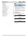
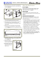
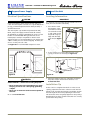
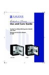
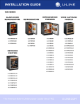
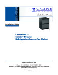
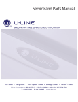
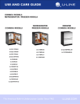
Installation Guide
CO2175FF —
Combo® Ice Maker/Refrigerator
www.U-LineService.com
Phone (414) 354-0300 • FAX (414) 354-7905
Service & Parts Tech Lines Phone (800) 779-2547 • FAX (414) 354-5696
[email protected]
©2006 U-Line Corporation
08/2006
CO2175FF — Combo® Ice Maker/Refrigerator
Contents
Exterior Cleaning . . . . . . . . . . . . . . . . . . . . . . . . . . . . . .
Cut-Out Dimensions . . . . . . . . . . . . . . . . . . . . . . . . . . .
Product Dimensions . . . . . . . . . . . . . . . . . . . . . . . . . . . .
Door Swing/Clearances Information . . . . . . . . . . . . . .
Reversing the Door. . . . . . . . . . . . . . . . . . . . . . . . . . . . .
Other Site Requirements . . . . . . . . . . . . . . . . . . . . . . . .
Side-By-Side Installation Instructions . . . . . . . . . . . . . .
Custom 1/4'' Door Panel Insert . . . . . . . . . . . . . . . . . . .
Full Overlay Door Panel . . . . . . . . . . . . . . . . . . . . . . . . .
Checking Door Alignment . . . . . . . . . . . . . . . . . . . . . .
Adjusting Door Alignment . . . . . . . . . . . . . . . . . . . . . .
Water Supply Connection . . . . . . . . . . . . . . . . . . . . . . .
Electrical Specifications . . . . . . . . . . . . . . . . . . . . . . . . .
Leveling Information . . . . . . . . . . . . . . . . . . . . . . . . . . .
Installation Tip . . . . . . . . . . . . . . . . . . . . . . . . . . . . . . . .
Installation of the CO2175FF . . . . . . . . . . . . . . . . . . . .
Relocating the Shelves . . . . . . . . . . . . . . . . . . . . . . . . .
Installation Troubleshooting . . . . . . . . . . . . . . . . . . . . .
Initial Start-Up . . . . . . . . . . . . . . . . . . . . . . . . . . . . . . . .
Start-Up Troubleshooting . . . . . . . . . . . . . . . . . . . . . . .
Service Information . . . . . . . . . . . . . . . . . . . . . . . . . . . .
1 Follow Safety Precautions
4
4
5
5
5
6
7
7
8
12
12
13
14
14
14
15
15
15
16
16
17
IMPORTANT
PLEASE READ all instructions completely before
attempting to install or operate the unit.
• This unit requires connection to the water supply.
Improper hook-up can result in substantial property
damage! If you are unsure of your ability to safely
connect the water supply to the unit, consult a licensed
plumber for assistance.
• This unit requires connection to a grounded (threeprong), polarized receptacle that has been placed by a
qualified electrician in accordance with applicable
electrical codes.
Safety Alert Definitions
Safety items throughout this guide are labeled with a
Danger, Warning or Caution based on the risk type:
DANGER
Danger means that failure to follow this safety
statement will result in severe personal injury or
death.
WARNING
Warning means that failure to follow this safety
statement could result in serious personal injury,
or death.
CAUTION
Caution means that failure to follow this safety statement
may result in minor or moderate personal injury, property
or equipment damage.
www.U-LineService.com
2
08/2006
CO2175FF — Combo® Ice Maker/Refrigerator
General Precautions
2 Inspect and Plan
Use this appliance for its intended purpose only and
follow these general precautions along with those listed
throughout this guide:
You have received a carton containing your CO2175FF
Ice Maker/Refrigerator with a package inside
containing a Use and Care Guide, a Product
Registration Card and water connection parts.
Complete and mail the Product Registration Card or
register online at www.U-LineService.com. Once your
unit is installed, keep the Use and Care Guide and this
Installation Guide in a safe place for future reference.
WARNING
SHOCK HAZARD — Electrical Grounding Required.
• Keep the unit unplugged throughout installation
except during testing.
• Never remove the round grounding prong from
the plug and never use a two-prong grounding
adapter.
Your unit is Black, White or Stainless Steel. Black and
White units have a reversible door with a slightly
contoured handle across the top. They come with a flush
mounted door panel that, when removed, will accept a
custom 1/4-inch thick door panel or a 3/4-inch thick full
overlay door panel. Stainless Steel units are covered with
a protective coating and have been ordered left- or righthand hinged. The Stainless doors are not reversible and do
not accept custom panels. Please carefully follow the
directions that apply to your unit and your intended design.
• Never use an extension cord to connect power to
the unit.
• Always keep your working area dry.
CAUTION
• Use care when moving and handling the unit. Use
gloves to prevent personal injury from sharp edges.
Tools/Materials Required
• Do not lift the unit by the door or door handle.
• Screwdrivers — slotted and Phillips head
• Do not install the unit behind closed doors or in any
way that would obstruct airflow to the front grille,
which may cause the unit to malfunction.
• 1/4-inch Outside Diameter copper tubing and shut-off
valve for water supply line
• 1/4-inch thick door panel material and cutting tools
(Black or White units) (If installing a 1/4” Panel)
• Full Overlay Door Panel Kit (part number U-OL2175B —
Black or part number U-OL2175W — White), 3/4-inch
door panel overlay, cutting tools, drill and bits (Black or
White units) (If installing a 3/4” Full Overlay)
Inspection
Unwrap and inspect the unit on a flat, level surface
capable of supporting its entire weight.
Removing Protective Coating
(Stainless Steel Units Only)
When inspecting/installing a Stainless Steel unit, the
protective coating covering the unit must be removed
first. Start at a corner of the unit/door and pull back the
protective coating to remove it from the unit/door.
08/2006
3
www.U-LineService.com
CO2175FF — Combo® Ice Maker/Refrigerator
After all the protective coating has been removed from
the unit/door, clean all Stainless Steel surfaces with Claire
Stainless Steel Polish and Cleaner or comparable product
or a mild detergent and warm water solution and soft
cloth. Do NOT use abrasive cleaning agents.
3 Prepare Site
Note: If cleaning with mild detergent and warm water
solution and soft cloth, the unit MUST be treated with
Claire Stainless Steel Polish and Cleaner or comparable
product to prevent discoloration.
Your U-Line product has been designed for either freestanding or built-in installation. When built-in, your unit
does not require additional air space for top, sides or rear.
However, the front grille must NOT be obstructed and
clearance is required for water, drain and electrical
connections in the rear.
Exterior Cleaning
Note: Unit can NOT be installed behind a closed cabinet
door.
(As Required)
Cut-Out Dimensions
Black and White Models:
• The door, grille and cabinet may be cleaned with a mild
detergent and warm water solution. Do not use
solvent-based or abrasive cleaners. Use a soft sponge
and rinse with clean water. Wipe with a soft, clean
towel to prevent water spotting.
See Electrical
Specifications
for Power Supply
Stainless Steel Models:
• Stainless steel models can discolor when exposed to
chlorine gas, pool chemicals, salt water or cleaners with
bleach.
24"
34-1/4"
to
35-1/8"
• Keep your stainless steel unit looking new by cleaning
with a good quality all-in-one stainless steel cleaner/
polish on a monthly basis. For best results use Claire
Stainless Steel Polish and Cleaner, which can be
purchased from U-Line Corporation. (The part number
is 173348.) Comparable products are acceptable.
Frequent cleaning will remove surface contamination
that could lead to rust. Some installations may require
cleaning on a weekly basis.
8"
24-3/16"
Figure 1
Follow the cut-out drawing in Figure 1. The 24-3/16"
width allows 1/4" for ease in installation and removal of
the unit. 24" is the cabinet depth in most installations.
The unit is 23-11/16" deep including the handle
on Black and White models and 23-11/16" deep including
the door and not the handle on Stainless Steel models
(see Figure 2).
• Do not clean with steel wool pads.
• Do not use cleaners that are not specifically
intended for stainless steel (this includes glass,
tile and counter cleaners).
• If any surface discolors or rusting appears, clean it
quickly with Bon-Ami or Barkeepers Friend Cleanser
and a non-abrasive cloth. Always clean in the direction
of the grain. Always finish this process with Claire
Stainless Steel Polish and Cleaner or comparable
product to prevent further problems.
• Use of abrasive pads such as Scotchbrite will
cause the graining in the stainless to become
blurred.
• Rust that is allowed to linger can penetrate into the
surface of the stainless steel and complete removal of
the rust may not be possible.
www.U-LineService.com
4
08/2006
CO2175FF — Combo® Ice Maker/Refrigerator
Product Dimensions
Reversing the Door
(Black and White Units Only)
23-11/16"
Including
Handle
All U-Line units
(except Stainless
Steel models) may be
left- or right-hand
opening. The door
opening is easily
reversed by moving
the hinge hardware
to the opposite side.
The top hinge
hardware will be
used on the bottom
of the other side and
the bottom hinge
hardware will be
used on the top of
the other side (see
Figure 4).
25-13/16"
Including
Handle
34-1/8"
34-1/8"
23-15/16"
23-15/16"
Black and White
Stainless Steel
Figure 2
Please note that the unit has adjustable feet that can add
one additional inch to height during leveling or to match
adjacent cabinets (see Figure 37 on Page 14).
To reverse the door:
Door Swing/Clearances Information
1. Remove top hinge Figure 4
ULIN_0015_A
screw pin from
door (Phillips screwdriver) (see Figure 5). Remove door
by tilting forward and lifting off bottom hinge pin.
Black and White units have a zero clearance for the door
to open 90° (see Figure 3). Stainless Steel models require
a minimum of 2-1/8" door clearance to accommodate the
handle if the unit is installed next to a wall or similar type
of structure.
Wall
2. Remove plastic screw plugs (3 each, top and bottom)
from new hinge location. Do not discard (see Figure 6).
Wall
1/4" Min.
2-1/8" Min.
Screw Plugs
21-7/16"
21-7/16"
Figure 6
25-1/2"
90°
Door Swing
Black and White
25-1/2"
90°
Door Swing
Figure 5
ULIN_0133_A
3. Remove top hinge (3 screws), reinstall hinge screw pin,
and remount on opposite side BOTTOM (see Figure 7).
Stainless Steel
Figure 3
08/2006
5
www.U-LineService.com
CO2175FF — Combo® Ice Maker/Refrigerator
Other Site Requirements
4. Remove the two door closer inserts from the existing
bottom hinge and install as shown on the new bottom
hinge (see Figure 8).
Power Supply
The unit requires a grounded and polarized 115 VAC,
60 Hz, 15A circuit (normal household current). See
Electrical Specifications on Page 14.
1
Water Supply
Door
Closer
Inserts
The unit requires a 1/4-inch Outside Diameter water
supply line and a shut-off valve. For more information see
Page 13.
Environmental Requirements
2
ULIN_0003_A
Figure 7
Many U-Line models are designed to operate in harsh
outdoor/marine environments. Special considerations
include the following:
Figure 8
5. Remove existing bottom hinge (3 screws) and remount
on opposite side TOP. Remove hinge screw pin.
• The units are designed to operate between 50°F (10°C)
and 110°F (40°C). High ambient temperatures (110°F
[40°C] or higher) may reduce the unit’s ability to reach
low temperatures and may also reduce the ice
production rate for those models with icemakers.
6. Remove the plastic hole plug from the top of the door
to allow the pivot pin to be inserted in the new
location. Install the plug into the vacated hole on the
opposite side.
• If the ambient temperature is expected to drop below
45°F (7°C), drain all water from the unit to prevent
freezing damage not covered by the warranty.
7. With bottom of door facing up, remove pivot plate
(2 screws), flip over, and remount on opposite side of
door (see Figure 9). Be sure notch in plate faces center.
• For best performance, keep the unit out of direct
sunlight and away from heat generating equipment.
• For best performance and life outdoors, place under a
counter or provide shelter of some kind.
• In climates where high humidity and dew points are
present, condensation may appear on outside surfaces.
This is considered normal. The condensation will
disappear when the humidity drops.
Figure 9
8. Holding door upright with top of door tilted forward,
place hole of door pivot plate on bottom hinge screw
pin (see Figure 10).
9. Tilt top of door into
position in top hinge and
install top hinge screw pin.
10. Install plastic screw plugs
removed in Step 2 in old
hinge holes (3 each, top
and bottom).
Figure 10
www.U-LineService.com
6
08/2006
CO2175FF — Combo® Ice Maker/Refrigerator
Side-By-Side Installation
Instructions
4 Prepare and Install Door Panel
(Black and White Units Only)
For a complete refreshment center, install your CO2175FF
Ice Maker/Refrigerator beside a U-Line Drawer or Wine
Captain Model (see Figure 11 for typical cut-out). Note
that each Side-By-Side Installation will be different.
Two types of custom door panels can be installed on your
Black or White unit to harmonize with or accent the
surrounding décor: a Custom 1/4" Insert or a Full Overlay.
If no custom door panel is used, go on to 5 Adjust Door.
• Cut-out width for a side-by-side installation is the total
of the widths listed under Cut-Out Dimensions in each
unit’s Installation Guide.
Custom 1/4'' Door Panel Insert
For example:
Door Panel Preparation
Placing a CO2175FF Ice Maker/Refrigerator next to a
2115 series unit would require a cut-out width of:
24-3/16" + 15-3/16" = 39-3/8"
A custom door panel can be inserted into the doorframe.
Custom door panels can be flat or raised, as long as the
maximum panel thickness where inserted into the door
reveal (channel) is 1/4"-thick. For raised panels, the depth
of the reveal is 1/4" on all four sides.
Placing a CO2175FF Ice Maker/Refrigerator next to a
2175 series unit would require a cut-out width of:
24-3/16" + 24-3/16" = 48-3/8"
IMPORTANT
• No trim kit is required. However, 1/4-inch space needs to
be maintained between the units to ensure
unobstructed door swing.
Raised panels will reduce the door’s 90° swing/zero
clearance if the unit is installed next to a wall or similar
type of structure.
• Units must operate from separate, properly grounded
electrical receptacles placed according to each unit’s
Electrical Specifications.
For 2175 models cut the panel insert to the following
dimensions.
Custom 1/4" Dimensions:
Typical Side-By-Side Cut-Out
Width:
Height:
23-1/32"
27-11/16"
For 2115 & CLR2160 models cut the panel insert to the
following dimensions.
Custom 1/4" Dimensions:
24"
34-1/4"
to
35-1/8"
Width:
Height:
7"
1/4" Space
Between
Appliances
14-1/32"
27-11/16"
The door panel must not weigh more than 20 lbs.
1-1/2"
Door Panel Installation
Figure 11
Install the insert as follows:
CAUTION
Use care when handling the insert. Insert edges may be
sharp.
1. Remove top hinge screw pin (using a Phillips
screwdriver, see Figure 12). Remove door by tilting
forward and lifting off bottom hinge pin.
08/2006
7
www.U-LineService.com
CO2175FF — Combo® Ice Maker/Refrigerator
Full Overlay Door Panel
Door Panel Preparation
A full overlay door panel completely covers the
doorframe and handle to give a built-in appearance. See
your U-Line dealer for the optional Full Overlay Door
Panel Kit.
2175 Models:
P/N U-OL2175B -- Black
P/N U-OL2175W -- White
ULIN_0133a_A
Figure 12
2115 & CLR2160 Models:
P/N U-OL2115B -- Black
P/N U-OL2115W --White
Figure 13
Appropriate hardware, Modified Handle, Replacement
Hinges and a copy of these instructions will be included in
the kit.
2. Pull door gasket out of groove (top edge of door only).
Start in the middle and pull outward, moving toward
the edge (see Figure 13). This may take some force.
1. Cut the overlay to the following dimensions (see
Figure 15).
3. Remove two outside screws holding door handle.
Slightly separate door handle from door (see
Figure 14).
Full Overlay Dimensions:
2175 Models:
Width: 23-3/4"
Height: 29-3/4"
4. Pull handle up and off.
5. Remove and discard
existing panel and
cardboard spacer.
2115 & CLR2160 Models:
Width: 14-3/4"
Height: 29-3/4"
The door panel must not weigh more than 20 lbs.
6. Slide custom door panel
insert into 1/4-inch
channel in door front.
3/4"
31/32"
7. Holding door gasket out
of the way, replace handle Figure 14
on door, making sure it is
seated properly on insert
and that screw holes line up.
1/8"
Relief Notch
for Pivot Plate
8. Install two small screws removed in Step 3.
9. Starting at the corners and working inward, push door
gasket into place on door.
10. Place door on bottom hinge pin and install upper hinge
screw.
Rear View
of
Wood Panel
Height
Width
Figure 15
ULIN_0400_A
IMPORTANT
Rear View of wood panel for right-hand hinge shown. Use
mirror image for left-hand hinges.
2. Create a relief (Figure 15) for pivot plate by cutting
notch in top corner of overlay panel. Refer to Figure
16 for exact specifications.
www.U-LineService.com
8
08/2006
CO2175FF — Combo® Ice Maker/Refrigerator
Installation Instructions
15/32"
Removing Existing Door
ø 0.177" (#16 Drill)
11/16" Deep
1. Remove the door shelves by first pulling shelves up at
a 45° angle, then straight out.
TOP VIEW
3/8"
2. Remove top hinge screw pin (Phillips screwdriver).
Remove the door by tilting forward and lifting off the
bottom hinge pin.
31/32"
.125"
3. Pull door gasket out of the groove (top edge of door only).
Start in the middle and pull outward, moving toward the
edge (see Figure 17). This may take some force.
11/16"
Ref
BACK VIEW
1/4" Ref
Old Handle
3/4" Min Ref
3/8"
BOTTOM VIEW
New Handle
SIDE VIEW
13/32"
Figure 16
ø 5/16" x 1/4" Deep
Chamfer 1/32" x 45°
ULIN_0401_A
Figure 17
Route notch in top corner of overlay panel as shown
(see Top and Side Views). Top of notch is entire depth
of panel, front to back.
Figure 18
ULIN_0403_A
4. Remove the two screws located on both sides of the
handle.
Width: 31/32"
5. Remove the handle and discard. (This handle will be
replaced with the Overlay Handle included in the Full
Overlay Door Panel Kit.)
Depth: 1/8"
CAUTION
6. Slide the existing door panel out of the doorframe.
Be careful not to drill too deep! Drilling holes too deep
may destroy your door panel.
Attaching the Full Overlay Panel
1. Place and tape the existing door panel on the back of the
overlay panel (see Figure 19) and drill holes through
both panels according to Figure 20. Remove tape
adjoining the panels and enlarge the six holes in the steel
(black/white vinyl color) panel using a 0.201" (#7) drill.
3. Drill hole for upper door hinge (top of panel) (see
Figure 16, Top View).
0.177" diameter
(#16 drill) x 11/16" deep
2. If a user-supplied cabinet handle will be used, attach its
hardware to the overlay panel at this time.
4. Drill hole for lower door hinge (see Figure 16, Bottom
View).
Removed
Door Panel
5/16" diameter x 1/4" deep
CAUTION
It is important to ensure that all drilled holes are drilled to
the correct depth in order to avoid splits in the wood
when hardware is installed.
Back of
Wood
Panel
Tape
1-3/4" Top
Side of
Wood Panel
Top of
Wood Panel
Figure 19
08/2006
9
3/8"
Both Sides
www.U-LineService.com
CO2175FF — Combo® Ice Maker/Refrigerator
IMPORTANT
2-5/8" ± 1/4"
Door panel and overlay panel must be aligned properly or
the door will not operate correctly.
Assembling the Door
Drill ø 5/32" x 3/8" Deep
7 Places Model 2175
6 places Model 2115 and CLR2160
15-9/16" ± 1/4"
1. Install the assembled panel by sliding the original door
panel back into the doorframe.
For use with #10 x 5/8"
Wood Screw and Nylon Spacer
2. Replace the Overlay Handle and secure with the two
screws removed in Step 4 under Removing Existing
Door.
3. Attach Overlay cap to door, opposite side of where
hinges will be (see Figure 23).
28-7/8" ± 1/4"
Overlay Cap
3/4" Wood Panel
1"
1"
11-7/8±1/32
For use on
Model 2175 Only
Replacement Handle
ULIN_0402_A
Figure 20
Attach the door panel to the overlay panel using #10 x 5/
8" wood screws and nylon spacers. The nylon spacers fit
between the overlay panel and the door panel as shown
in Figure 21. The spacers allow the original door panel
to slide back into the 1/4"-thick door reveal (channel).
Typical
Wood Panel
Figure 23
4. Attach Top Pivot Plate to door handle, on side where
hinges will be. Use the two #8-32 x 1/2" Flat Head
Phillips screws (Black) supplied with kit (see Figure 24).
Door Panel
#8-32 x 1/2" Flat Head Screws
Black, Two Places
3/4" Wood Overlay
#10 x 5/8"
Round Head Screw
Seven Required
Figure 21
Top Pivot Plate
Screw to attach Handle
Removed in step 4
Plastic Spacer
Seven Required
Figure 24
3. Remove the existing bottom pivot plate and replace
with the Full Overlay pivot plate (see Figure 22).
5. Starting at the corners and working toward the center,
push the door gasket back into place.
Installing the Door
Existing
Door
Existing Bottom Pivot Plate
(Remove and Discard)
1. Remove the existing hinges from the unit, saving the
door closure assembly.
Wood Panel Bottom Pivot Plate
(5/8" Longer Than
Existing Bottom Pivot Plate,
Flush Side Facing Out)
2. Install the new Replacement Top Hinge onto the unit
(see Figure 25).
#8-32 x 3/8" SEMS Hex Screw
Two Places
Figure 22
www.U-LineService.com
10
08/2006
CO2175FF — Combo® Ice Maker/Refrigerator
Checking Door Alignment
Wood Panel Top Hinge Plate
(5/8" Longer than Existing Top Hinge Plate)
The unit’s door is aligned at the factory before shipment.
However, its alignment could have been disturbed during
shipment or during door panel installation.
Pivot Post
IMPORTANT
Properly aligned, the door should be 1/8" below the top of
the unit’s cabinet, NOT flush with the top (see Figure 28).
#8-32 x 1/2"
Flat Head Screw
Three Places
Top Pivot Plate
1/8"
Door Panel
Figure 25
ULIN_0405
3. Install the pivot post into the new Replacement Bottom
Hinge (using the Phillips screwdriver) and install the
hinge onto the unit.
Figure 27
1. Compare the top edge of the door to the top edge of
the cabinet.
4. Replace the door closure assembly onto the bottom
pivot post (see Figure 26). Be sure that bosses on
closers align with holes in hinge and hinge plate.
2. If the door edge is 1/8" below and parallel to the top of
the cabinet, the door is aligned. If it is not, note
whether the side opposite the hinge needs to be moved
UP or DOWN, and use the following procedure.
3. If door is adjusted correctly, but panel is not square
with the adjacent cabinets, slight adjustments can be
made by drilling the holes in the vinyl coated steel
panel slightly oversized. See Figure 20 on Page 10.
Existing Door
Door Closure Top
Boss
Door Closure
Bottom
Boss
Pivot Post
#8-32 x 1/2" Flat Head Screw
Three Places
Wood Panel Bottom Hinge Plate
(5/8" Longer than Existing Bottom Hinge Plate)
Figure 26
IMPORTANT
Pivot posts must be cleaned. Closers must also be clean
and greased to ensure proper operation.
5. Place the modified door onto the pivot post.
6. Position door and install the pivot post into the top
hinge (using the Phillips screwdriver).
7. Adjust door as needed for proper closure.
8. Check to see that light goes off when the door closes.
9. Reinstall the door shelves by lining up the bosses and
first pushing straight in, then down at a 45° angle.
08/2006
11
www.U-LineService.com
CO2175FF — Combo® Ice Maker/Refrigerator
5 Adjust Door
Checking Door Alignment
The unit’s door is aligned at the factory before shipment.
However, its alignment could have been disturbed during
shipment or during door panel installation.
Slotted
Mounting
Holes
Notch
IMPORTANT
Properly aligned, the door should be 1/8" below the top of
the unit’s cabinet, NOT flush with the top (see Figure 28).
Raise
Outside
Door Edge
Lower
Outside
Door Edge
Figure 30
1/8"
3. See Figure 30. If the top far edge of the door needs to
move UP, move the hinge plate toward the outside of
the door and retighten screws. If the top far edge of the
door needs to move DOWN, move the hinge plate
toward the inside of the door and retighten screws.
Figure 28
4. Mount the door to recheck alignment and repeat Steps
2 and 3 if further adjustment is necessary.
1. Compare the top edge of the door to the top edge of
the cabinet.
5. When top edge of door is parallel to top edge of
cabinet, remove the door and ensure the two screws
are secure.
2. If the door edge is 1/8" below and parallel to the top of
the cabinet, go on to 6 Prepare Plumbing. If it is not,
note whether the side opposite the hinge needs to be
moved UP or DOWN, and use the following procedure.
6. Remove the door closers from the bottom hinge, clean
thoroughly and lubricate the mating surfaces with
petroleum jelly.
Note: If door is adjusted correctly, but panel is not square
with the adjacent cabinets, slight adjustments can be
made by drilling the holes in the vinyl coated steel panel
slightly oversized. See Figure 21 on Page 10.
7. Reinstall the closers, lining
up the bosses with holes in
hinge and hinge plate (see
Figure 31).
Adjusting Door Alignment
8. Mount the door, install top
hinge pivot pin and go on
to 6 Prepare Plumbing.
1. Remove top hinge screw
pin (Phillips screwdriver,
see Figure 29). Remove
door by tilting forward
and lifting off bottom
hinge pin.
Boss
2. With door upside-down,
loosen but do not remove
the two screws on the
door’s bottom hinge plate.
Figure 31
Figure 29
www.U-LineService.com
Door
Closer
Inserts
ULIN_0133_A
12
08/2006
CO2175FF — Combo® Ice Maker/Refrigerator
2. Locate the compression fitting and ferrule packed with
the unit. Slide the compression fitting and ferrule over
the 1/4-inch OD water supply line. Do not use thread
sealing compound or tape. Using two wrenches,
tighten the compression fitting on the supply line (see
Figure 33).
6 Prepare Plumbing
CAUTION
Plumbing installation must observe all state and local
codes. All water connections MUST BE made by a licensed/
qualified plumbing contractor. Failure to follow
recommendations and instructions may result in damage
and/or harm.
3. Carefully bend the water supply line into position and
connect the line to the solenoid valve (see Figure 34).
Avoid kinking the water supply line.
WARNING
To prevent accidental electrocution, make certain
that the floor surfaces surrounding the unit are
dry whenever power is removed from, or applied
to, the unit.
Water Supply Connection
When connecting the water supply, follow these
guidelines:
• Review the local plumbing codes before you install the
unit.
• Connect to the cold water supply.
• The water pressure should be between 20 and 120 psi.
• Install a shut-off valve in the 1/4 inch Outside Diameter
water supply line.
• Connect sufficient tubing to the unit so that tubing
may be looped, allowing the unit to be removed for
cleaning and servicing (see Figure 34). However, make
certain that the tubing is not pinched or damaged
during installation.
Figure 34
IMPORTANT
Normal operation creates some vibration. A water supply
line contacting cabinet wall may cause excessive noise
during operation or damage to the line.
4. For recessed installations, allow extra water supply line
length to provide slack for easy removal from the
recessed area (see Figure 34). This will also safeguard
against kinking the line.
Note: U-Line recommends the use of copper tubing
for installation. The use of other types of tubing is not
recommended due to potential aftertaste & deterioration
over time.
5. Go on to 7 Prepare Power Supply.
To connect to water supply:
1. Install the 1/4 inch OD copper water line from the
main water source (see Figure 32).
Water
Connection
Figure 32
08/2006
Figure 33
13
www.U-LineService.com
CO2175FF — Combo® Ice Maker/Refrigerator
7 Prepare Power Supply
8 Level the Unit
Electrical Specifications
Leveling Information
CAUTION
IMPORTANT
It is extremely important that the unit is level. If it is not
level, the ice mold will not fill evenly.
Electrical installation must observe all state and local
codes. This unit requires connection to a grounded (threeprong), polarized receptacle that has been placed by a
qualified electrician.
1. Use a level to check
the levelness of the
ice maker from front
to back and from side
to side. Level should
be placed along top
edge and side edge
as shown (see Figure
36).
The unit requires a grounded and polarized 115 VAC,
60 Hz, 15A power supply (normal household current).
An individual, properly grounded branch circuit or circuit
breaker is recommended. GFCI (ground fault circuit
interrupter) is usually not required for fixed location
appliances and is not recommended for your unit because
a GFCI could be prone to nuisance tripping. However, be
sure to consult your local codes.
1
See Figure 35 for recommended receptacle location.
Figure 36
ULIN_0193_A
2. If the ice maker is not level, adjust the feet on the
corners of the unit as necessary (see Figure 37).
24"
7"
1-1/2"
Turn Foot to Adjust
Figure 37
Figure 35
3. Check the levelness after each adjustment and repeat
the previous steps until the unit is level. Go on to
9 Install the Unit.
WARNING
SHOCK HAZARD — Electrical Grounding Required.
Installation Tip
• Never remove the round grounding prong from
the plug and never use a two-prong grounding
adapter.
If the room floor is higher than the floor in the cut-out
opening, adjust the rear feet to achieve a total unit rear
height of 1/8" less than the opening’s rear height. Shorten
the unit height in the front by adjusting the front feet.
This allows the unit to be gently tipped into the opening.
Readjust the front feet to level the unit after it is correctly
positioned in the opening.
• Never use an extension cord to connect power to
the unit.
Go on to 8 Level the Unit.
www.U-LineService.com
14
08/2006
CO2175FF — Combo® Ice Maker/Refrigerator
Door Shelves
9 Install the Unit
1. First pull shelf up at a 45°
angle, then straight out
(see Figure 39).
Installation of the CO2175FF
1. Open the water supply valve in the main water source.
Notch
2. Choose new location and
line up on bosses. First
push straight in, then
down at a 45° angle.
2. Plug in the powercord.
3. Open the door and press the POWER icon (see Figure
40,1). to turn the unit OFF.
Boss
Note: If the unit is NOT turned OFF, water will
immediately start flowing into the unit when it is first
plugged into the electrical outlet.
4. Gently push the unit into position. Be careful not to
kink the water supply line or entangle the electrical
cord.
Figure 39
Installation Troubleshooting
5. Re-check the leveling, from front to back and side to
side. Make any necessary adjustments. The unit’s top
surface should be approximately 1/8" below the
countertop.
Q:
Problem
Water is leaking under the unit.
6. Remove the tape from the glass shelves and wipe out
the inside of the unit with a clean, water-dampened
cloth.
A:
Solution
A water leak under the unit is most likely caused by a bad
connection in the water supply line. Make sure the water
line’s brass fitting is screwed tight to its valve and
threaded correctly.
Relocating the Shelves
Both the glass shelves in the refrigerator and the inner
door shelves can be moved to accommodate your bottles,
cans and containers.
Q:
Glass Shelves on Right-Hand Hinge Units
Problem
The door remains open unless it is pushed closed.
1. Open door fully, grasp shelf firmly, lift front edge
slightly, and pull straight out.
A:
2. Choose new location and slide shelf onto the
appropriate rib.
The hinges should be self-closing when the door is open
approximately 8". If this is not the case, make sure the
closers (at the bottom of the hinge pin) are clean, greased
and installed correctly. Also, re-check leveling from front
to back of the unit and readjust if necessary. Make sure
that pivot plate is installed correctly.
Glass Shelves on Left-Hand Hinge Units
1. See Figure 38. Pull shelf
out about 6” to clear the
wall’s molded protrusion.
2. Tilt right-hand edge of
shelf up.
08/2006
Problem
The custom overlay door was designed to align with the
rest of the cabinet doors, but the unit has crept forward.
3. Pull
2. Tilt
3. Keeping at this angle and
hugging the right wall,
pull the shelf out.
4. Choose new location and
insert over ribs, tilting
right-hand edge up. Push
in, then lower shelf onto
ribs.
Q:
1. Pull Out 6"
Solution
A:
Solution
Make sure that the electrical cord and water supply line
are not obstructing the installation.
Figure 38
15
www.U-LineService.com
CO2175FF — Combo® Ice Maker/Refrigerator
About Settings
10 Start-Up for the First Time
No adjustments should be necessary at this time. For
information about Adjusting the Temperature Control
and Adjusting the Cube Size, see the Use and Care Guide.
Initial Start-Up
Once installation and leveling is complete, the unit is
ready for initial start-up and operation. The POWER icon
is located inside the unit.(see Figure 40,1).
1
2
3
4
Start-Up Troubleshooting
Q:
Problem
Unit does not appear to turn on when POWER icon is
pressed.
5
A:
Solution
Make sure unit is plugged in and outlet has power (circuit
breaker has not tripped). Remember that the ice maker
mechanism will not fill the mold with water until the
mold reaches the proper temperature.
ULIN_0058_A
Figure 40
1. The unit should already
be plugged into the
electrical outlet. Make
sure the water supply is
turned on.
Q:
Problem
Water does not appear to be flowing into unit.
A:
2. Open the door and press
the POWER icon on the
display to turn the unit on
(see Figure 40,1).
Solution
Check that the water is connected and turned on and the
line is not obstructed.
Q:
3. As soon as the ice maker
mold reaches the proper
Figure 41
temperature, the ice
maker mechanism will fill the mold with water.
Problem
The cubes produced during the first two to three hours of
operation have been discarded. New cubes still appear
cloudy.
Note: The first cubes may be small because of air in the
water line. After two hours, cubes will be standard size.
A:
4. The ice maker will continue to produce until the bin is
full. You may interrupt production by raising the bin
arm into an upright and locked position (see Figure
41). While the bin arm is locked, the unit will maintain
temperature for ice storage.
This is normal and is caused by air being trapped in the
cube during fast freezing.
Solution
IMPORTANT
See the Use and Care Guide’s Troubleshooting Guide for
more solutions.
IMPORTANT
It is possible that dirt or scale will dislodge in the water
line. Always throw away all ice cubes made during the
first twenty-four (24) hours of operation.
CAUTION
• The ice bucket MUST be fully inserted to avoid freezing
products in the refrigerator section. The ice bin door
must be fully closed with the door lip inside the ice
bucket.
• Do not place cans or bottles so they are touching the
back wall of the refrigerator section, as they may
freeze.
• Do not place any objects over air inlet or outlet in the
freezer section.
www.U-LineService.com
16
08/2006
Who to Call
Service Information
If the need for service arises, call the U-Line Customer
Care Center directly @ 800-779-2547. To ensure accurate
assistance, please have your Model Number and Serial
Number and an explanation of the problem. The Model
and Serial Number plate is located inside unit at upper
right hand corner.
If you need to locate a service company, you can go online
at www.U-LineService.com and search for a service
company by zip code.
For more than four decades, U-Line has distinguished itself as the leader in built-in
undercounter ice making, refrigeration and wine storage appliances.
U-Line Corporation, located in Milwaukee, WI, is a family operated manufacturer of built-in
undercounter icemakers, Combo® icemaker/refrigerators, Wine Captain® wine storage units,
refrigerators, refrigerated drawers and refrigerator/freezers.
©2006 U-Line Corporation
Publication No. 30150E
08/2006 Rev. B