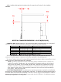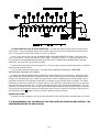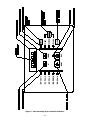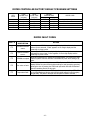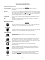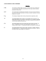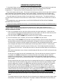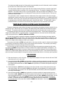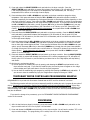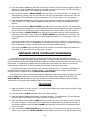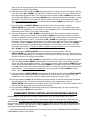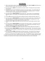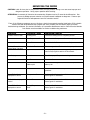
1
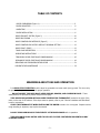
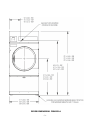
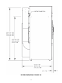
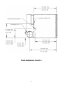
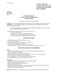
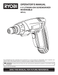
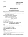
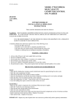
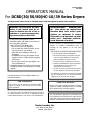
OPERATOR’S MANUAL
8514-209-001A
May 2012
For DCBD(30/50/80)HC-10/39 Series Dryers
The dryer must not be stored or installed where it will be exposed to water and/or weather.
WARNING: For your safety the information in this manual must be followed to minimize the risk of fire or
explosion or to prevent property damage, personal injury or loss of life.
-Do not store or use gasoline or other
flammable vapors and liquids in the vicinity of
this or any other appliance.
– WHAT TO DO IF YOU SMELL GAS
• Do not try to light any appliance.
• Do not touch any electrical switch; do not
use any phone in your building.
• Clear the room, building or area of all
occupants.
• Immediately call your gas supplier from a
neighbor’s phone. Follow the gas supplier’s
instructions.
• If you cannot reach your gas supplier, call
the fire department.
– Installation and service must be performed by
a qualified installer, service agency or the gas
supplier.
Post the following “For Your Safety” caution in a
prominent location:
AVERTISSEMENT.
Assurez-vouz
de bien suivre les instructions
données dans cette notice pour
réduire au minimum le risque
d’incendie ou d’explosion ou pour
éviter tout dommage matérial,
toute blessure ou la mort.
Ne pas entreposer ni utiliser d’essence ni d’autres
vapeurs ou liquides inflammables dans le
voisinage de cet appareil ou de tout autre
appareil.
– QUE FAIRE SI VOUS SENTEZ UNE ODEUR DE GAZ:
• Ne pas tenter d’allumer d’appareil.
• Ne touchez à aucun interrupteur. Ne pas
vous servir des téléphones se trouvant
dans le bâtiment où vous trouvez.
• Évacuez la pièce, le bâtiment ou la zone.
• Appelez immédiatement votre fournisseur
de gaz depuis un voisin. Suivez les
instructions du fournisseur.
• Si vous ne pouvez rejoindre le fournisseur
de gaz, appelez le service des incendies.
– L’installation et l’entretien doivent être assures
par un installateur ou un service d’entretien
qualifie ou par le fournisseur de gaz.
FOR YOUR SAFETY
Do not store or use gasoline or other flammable
vapors or liquids in the vicinity of this or any
other appliance.
It is important that you read this Manual and retain it
for future reference. For service or replacement parts,
contact the distributor in your area or the manufacturer.
POUR VOTRE SÉCURITÉ
Ne pas ente poser ni utiliser d’essence ni d’autres
vapeurs ou liquides inflammables dans le voisinage
de cet appareil ou de tout autre appareil.
You, the purchaser, must post in a prominent location instructions to be followed in the event the user
smells gas. Consult your local gas supplier for procedure to be followed if the odor of gas is present.
Dexter Laundry Inc.
2211 West Grimes Avenue
Fairfield, Iowa 52556
TABLE OF CONTENTS
DRYER DIMENSIONS (Figure 1)..................................…...................................3
DRYER CAPACITIES.................................................................….................
6
UNCRATING ...........….................................................................…................. 6
DRYER INSTALLATION ................................................................................... 6
DRYER EXHAUST SYSTEM (Figure 2) ............................................................... 10
DRYER SHUTDOWN ....................................................................................... 10
DRYER CONTROLLER INTERFACE (Figure 3) …………………………………………………. 11
DRYER CONTROLLER FACTORY DEFAULT PROGRAM SETTING .......................... 12
DRYER FAULT CODES ..........................…........................................................ 12
TOUCH PAD DESCRIPTION .................…......................................................... 13
OPERATING INSTRUCTIONS ........................................................................... 15
TEMPORARY DRYER CONTROLLER PROGRAMMING ......................................... 16
PERMANENT DRYER CONTROLLER PROGRAMMING ......................................... 18
SERVICING AND TROUBLESHOOTING DRYER ................................................... 21
PREVENTATIVE MAINTENANCE .......................…............................................. 22
WARNINGS ABOUT USE AND OPERATION
It is ABSOLUTELY ESSENTIAL that the dryer be grounded to a known earth (zero) ground. This is not only
for personal safety, but is necessary for proper operation.
DO NOT MODIFY THIS APPLIANCE. KEEP SHIELDS, GUARDS, AND COVERS IN PLACE. These
safety devices are provided to protect everyone from injury.
THIS DRYER IS EQUIPPED WITH AN OVER-TEMPERATURE THERMOSTAT located to the right of the
motor on the rear of the cabinet. If the dryer cease to operate, refer to your “Service Procedure and Parts Data”
book for instructions.
CHECK THIS THERMOSTAT WHEN INSTALLING THE DRYER to assure it is not tripped. Impacts such as
rough handling in shipment, may trip the thermostat.
DO NOT SPRAY AEROSOLS IN THE VICINITY OF THIS APPLIANCE while in operation.
THIS APPLIANCE SHALL NOT BE USED TO DRY OFF CLOTHES CONTAINING SOLVENTS OR DRY
CLEANING FLUIDS.
-2-
DRYER DIMENSIONS- FIGURE 1A
-3-
DRYER DIMENSIONS- FIGURE 1B
-4-
DRYER DIMENSIONS- FIGURE 1C
-5-
DRYER CAPACITIES
Dryer Model
DCBD30
DCBD50
DCBD80
Dry Weight Capacity
30 lb (13.6 kg)
50 lb (22.7 kg)
80 lb (36.3 kg)
INSTALLATION AND OPERATING INSTRUCTIONS
INDUSTRIAL DRYER
UNCRATING
Tools required: 3/4” hex socket and ratchet driver, knife, channel-lock wrench that opens to 1 3/8".
1. Remove the plastic wrap with knife. Remove cardboard rails, fillers and top cap.
2. Using a ratchet and a 3/4” socket, remove the (4) bolts attaching the wooden skid to the dryer cabinet. Save
the bolts for future moving of the dryer.
3. With a walking motion, move the dryer forward completely off the wooden skid. Save the skid for future
moving of the dryer.
4. Using the channel-lock wrench, adjust the leveling legs to align the machine with adjacent units.
Note: If the dryer is ever moved again, the dryer should be re-mounted on its pallet and its crating bolts reinserted and tightened, in the reverse order as above.
DRYER INSTALLATION
1. CODE CONFORMITY. All commercial dryer installations must conform with local codes or, in the absence
of local codes, with the latest edition of the National Fuel Gas Code ANSI Z223.1A. Canadian installations must
comply with current Standard CAN/CGA-B149 (.1 or .2) Installation Code for Gas Burning Appliances or Equipment,
and local codes if applicable. Australian installations must meet installation requirements and pipe sizing
requirements of AS/NZA 5601. The appliance, when installed, must be electrically grounded in accordance with
the latest edition of the National Electrical Code, ANSI/NFPA70, or, when installed in Canada, with Standard CSA
C22.1 Canadian Electrical Code Part 1.
2. INSTALLATION CLEARANCES. This unit may be installed at the following alcove clearance. (millimeters)
I. Left Side
0”
II. Right Side
0” *
III. Back
18” (457) (Certified for 1” (25) clearance; however, 18” (457) clearance is necessary behind
the belt guard to allow servicing and maintenance.)
IV. Front
48” (1220) (to allow use of dryer)
V. Top
Refer to figure on the next page labeled “Vertical Clearance Dimensions”.
Certification allows 0” clearance at the top 1” (25) back from the front. However, a 1/4” (6)
clearance is required to allow opening the upper service door.
A 10” (254) clearance is required from the top at all other points.
VI. Floor
This unit may be installed upon a combustible floor.
*Units may be installed in direct contact with an adjacent dryer, providing allowance is made for opening
upper and lower service doors.
Do not obstruct the flow of combustion and ventilation air.
Maintain minimum of 1” (25) clearance between duct and combustible material.
-6-
Refer to installation label attached to the inside surface of the upper door of the dryer for other installation
information.
VERTICAL CLEARANCE DIMENSIONS - ALL DCBD(30/50/80)
3. MAKE-UP AIR. Adequate make-up air must be supplied to replace air exhausted by dryers on all types of
installations. Provide a minimum make-up air opening to the outside for each dryer as follows:
Dryer Model
DCBD30HC-10
DCBD30HC-39
DCBD50HC-10
DCBD50HC-39
DCBD80HC-10
DCBD80HC-39
Make-up Air Volume/Time
830 CFM (23.5 m3/minute)
690 CFM (19.5 m3/minute)
850 CFM (23.5 m3/minute)
700 CFM (19.8 m3/minute)
1200 CFM (34.0 m3/minute)
1000 CFM (28.3 m3/minute)
Make-up Air Opening Area (minimum)
1 ft² (0.10 m2)
1 ft² (0.10 m2)
1.25 ft² (0.12 m2)
1.25 ft² (0.12 m2)
1.5 ft² (0.14 m2)
1.5 ft² (0.14 m2)
This is a net requirement of effective area. Screens, grills or louvers, which will restrict the flow of air, must be
considered. Consult the supplier to determine the free area equivalent for the grill being used.
The source of make-up air should be located sufficiently away from the dryers to allow an even airflow to the air
intakes of all dryers. Multiple openings should be provided.
NOTE: The following considerations must be observed for gas dryer installations where dry cleaners are
installed. The sources of all make-up air and room ventilation air movement to all dryers must be located
away from any dry cleaners. This is necessary so that solvent vapors will not be drawn into the dryer
inlet ducts. Dry cleaner solvent vapors will decompose in contact with an open flame such as the gas
flame present in clothes dryers. The decomposition products are highly corrosive and will cause damage
to the dryer(s), ducts and clothes loads.
4. ELECTRICAL REQUIREMENTS. The electrical power requirements necessary to operate the unit satisfactorily
are listed on the serial plate located on the back panel of each dryer. The electrical connection should be made to
the terminal block in the rear control box assembly on the rear of the unit, using a wire size adequate to handle the
amperage and voltage listed on the serial plate, but never smaller than No.12 AWG wire. It is absolutely necessary
that the dryer be grounded to a known ground.
-7-
Individual circuit breakers for each unit are recommended. The wiring diagram is located on the belt guard on
the back of the machine.
IMPORTANT: TRANSIENT VOLTAGE SURGE SUPPRESSORS
Like most electrical equipment, your new machine can be damaged or have its life shortened by voltage surges
due to lightening strikes which are not covered by factory warranty. Local power distribution problems also can
be detrimental to the life of electrical components. We recommend the installation of transient voltage surge
suppressors for your new equipment. These devices may be placed at the power supply panel for the complete
installation and don’t require an individual device for each machine.
These surge protectors help to protect equipment from large spikes and also from small ongoing spikes in the
power that occur on a day to day basis. These smaller surges can shorten overall life of electrical components of
all types and cause their failure at a later date. Although they can’t protect against all events, these protective
devices have a good reputation for significantly lengthening the useful life of electronic components. Electronic
components are helped to have a longer useful life when they are supplied with the clean stable electrical power
they like.
We are including the following names and phone numbers of a few suppliers of these devices for those who don’t
currently have a source.
MANUFACTURER
CONTACT
PHONE
Innovative Technology, Inc (Eaton)
Factory
EFI Electronics Corporation
(Schneider Electric)
Factory
1-800-877-1174 or www.efinet.com
Distributor – Surge Pro 1-877-233-0153
MCG Surge Protection
Factory
1-800-647-8877 or www.itvss.com
1-800-851-1508 or www.mcgsurge.com
Advanced Protection Technologies Inc. Factory
1-800-237-4567 or www.aptsurge.com
5. GAS REQUIREMENTS. The complete gas requirements necessary to operate the dryer satisfactorily are
listed on the serial plate located on the back panel of the dryer.
The inlet gas connection to the unit is 1/2 inch pipe thread.
A joint compound resistant to the action of liquefied petroleum gases should be employed in making pipe
connections.
A 1/8 inch NPT plugged tapping, accessible for test gage connection, must be installed immediately upstream
of the gas supply connection to the dryer.
A drip tee should be provided in the gas piping entering the unit to catch dirt and other foreign articles.
All pipe connections should be checked for leakage with soap solution. Never check with an open flame.
For altitudes above 2,000 feet (610m) it is necessary to derate the BTU input. Contact your local distributor for
instructions.
L.P. gas conversion kits are available for this dryer. Contact your local distributor.
CAUTION: The dryer and its individual shutoff valve must be disconnected from the gas supply piping system
during any pressure testing of that system at test pressures in excess of 1/2 psig. The dryer must be isolated from
the gas supply piping system by closing its individual manual shutoff valve during any pressure testing of the gas
supply piping system at test pressures equal to or less than 1/2 psig.
6. EXHAUST INSTALLATION. (Refer to Figure 2 at the end of section 6.) Exhausting of the dryer(s) should
be planned and constructed so that no air restrictions occur. Any restriction due to pipe size or type of installation
can cause slow drying time, excessive heat, and lint in the room.
From an operational standpoint, incorrect or inadequate exhausting can cause a cycling of the high limit thermostat
which shuts off the main burners and results in inefficient drying.
Individual exhausting of the dryers is recommended. All heat, moisture, and lint should be exhausted outside
by attaching a pipe of the proper diameter to the dryer adapter collar and extending it out through an outside wall.
-8-
This pipe must be very smooth on the inside, as rough surfaces tend to collect lint which will eventually clog the
duct and prevent the dryer from exhausting properly. All elbows must be smooth on the inside. All joints must be
made so the exhaust end of one pipe is inside the next one downstream. The addition of an exhaust pipe
tends to reduce the amount of air the blower can exhaust. This does not affect the dryer operation if held within
practical limits. For the most efficient operation, it is recommended that no more than 20' (6m) of straight 8”
diameter pipe be used with two right angle elbows. When more than two elbows are used, 2' (600mm) of straight
pipe should be removed for each additional elbow. No more than four right angle elbows should be used to
exhaust a dryer.
Maintain minimum 1” (25) clearance between duct and combustible material.
If the exhaust pipe passes through a wall, a metal sleeve of slightly larger diameter should be set in the wall and
the exhaust pipe passed through this sleeve. This practice is required by some local codes and is recommended in
all cases to protect the wall. This type of installation should have a means provided to prevent rain and high winds
from entering the exhaust when the dryer is not in use. A hood with a hinged damper can be used for this purpose.
Another method would be to point the outlet end of the pipe downward to prevent entrance of wind and rain. In
either case, the outlet should be kept clear, by at least 24” (610), of any objects which would cause an air
restriction.
Never install a protective screen over the exhaust outlet.
When exhausting a dryer straight up through a roof, the overall length of the duct has the same limits as exhausting
through a wall. A rain cap must be placed on top of the exhaust and must be of such a type as to be free from
clogging. The type using a cone shaped “roof” over the pipe is suitable for this application.
Exhausting the dryer into a chimney or under a building is not permitted. In either case there is a danger of
lint build-up which can be highly combustible.
Installation of several dryers, where a main discharge duct is necessary, will need the following considerations for
installation (see Fig. 2). Individual 8” (200mm) ducts from the dryers into the main discharge duct should be at a
45 degree angle in the direction of discharge air flow.
NOTE: Never install the individual 8” ducts at a right angle into the main discharge duct. The
individual ducts from the dryers can enter at the sides or bottom of the main discharge duct. Figure 2
indicates the various round main duct diameter to use with the individual dryer ducts. The main duct can be
rectangular or round, provided adequate air flow is maintained. For each individual dryer, the total exhausting
(main discharge duct plus duct outlet from the dryer) should not exceed the equivalent of 20 feet (6m) and
two elbows. The diameter of the main discharge duct at the last dryer must be maintained to exhaust end.
NOTE: A small diameter duct will restrict air flow; a large diameter duct will reduce air velocity – both
contributing to lint build up. An inspection door should be provided for periodic clean-out of the main
duct.
NOTE: STATIC BACK PRESSURE should be a maximum of 0.3 at the rear exhaust outlet of the dryer. If
multiple dryers are connected to the common duct, ensure the back draft damper is installed properly.
-9-
7. DRYER IGNITION (SOLID STATE IGNITION). The solid state ignition system lights the main burner
gas by spark. The gas is ignited and burns only when the gas-valve relay (in the electronic controller) calls for
heat. The procedure for first-time starting of a dryer is as follows:
A. First, review and comply with the “WARNINGS ABOUT USE AND OPERATION” found on the inside front
cover of this manual. Be sure the electrical power supply is connected correctly. The white (neutral) wire is to
be connected to the N terminal while the black (line) wire to the L1 terminal of the terminal block in the rear
control box. The dryer MUST be properly grounded.
B. Make sure all gas supply lines are purged of air. Close the main gas shut-off valve and wait for five minutes
before turning the valve back on.
C. Turn on main electrical power switch. The dryer may be started by following the “OPERATING
INSTRUCTIONS” found later in this manual.
D. Natural gas and liquefied petroleum gas fired dryers both operate in the same manner. When gas-valve
relay contacts are closed (indicating a demand for heat), the solid state ignition control will automatically supply
energy to the redundant gas valve. Spark will continue until a flame is detected by the sensing probe, but not
longer than 10 seconds. If the gas fails to ignite within 10 seconds, the gas will shut off for 15 seconds. The control
will attempt to ignite two more times in a similar manner. If the gas fails to ignite after three tries, the gas valve
closes and the system will "lock out". No further attempts at ignition will be performed automatically. It is then
necessary to interrupt electrical power to the ignition system before making another attempt to light the burners.
This can be done by opening the dryer door, allowing the dryer to come to a stop for 15 seconds, closing the door,
button. The dryer will then repeat the ignition trial cycle.
and pushing the "Start"
DRYER SHUTDOWN
To render the dryer inoperative, turn off the main gas shut-off valve and disconnect electrical power to the dryer.
IT IS RECOMMENDED THAT THE INSTALLER TEST THE DRYER FOR OPERATION AND INSTRUCT THE
USER BEFORE LEAVING THE INSTALLATION.
- 10 -
Figure 3 – Non-Reversing Dryer Controller Interface.
- 11 -
DRYER CONTROLLER FACTORY DEFAULT PROGRAM SETTINGS
DRY
CYCLE
1
2
3
4
5
COOL
DOWN TIME
(minutes)
5
2
5
2
2
TOTAL
CYCLE TIME
(minutes)
35
20
25
20
25
DRYING
TEMPERATURE
(ºF)
(ºC)
180
82
170
77
180
82
130
54
175
79
DRYER LOAD
Towels, pads, heavy cotton
Sheets, blended materials
Cotton
Synthetic Materials
Blended Materials
DRYER FAULT CODES
FAULT #
FAULT
DESCRIPTION
F1
Shorted thermostat
sensor.
F2
Open thermostat
sensor.
F3
EEPROM corrupted.
F4
Gas valve on fault.
F5
Temperature fault.
ACTION
Dryer stops and “F1” flashes on the 4-digit display. When short circuit on
sensor input is removed, “LOAd” appears on the 4-digit display and the
remaining dry time is reset.
Dryer stops and “F2” flashes on the 4-digit display. When a good sensor is
connected to sensor input, “LOAd” appears on the 4-digit display and the
remaining dry time is reset.
Dryer will not start and “F3” appears on the 4-digit display. The power to the dryer
must be cycled to reset the controller. Fault should only occur when starting a dry
cycle.
The drying temperature did not increase 1°F. in 5 minutes. “F4” will flash on the
display and the dry cycle will finish without calling for heat (energizing gas valve).
Opening the door or pressing the STOP touch pad switch will reset the fault and
clear the remaining time in the dry cycle.
The drying temperature is at least 25°F. above the temperature setting. “F5” will flash
on the 4-digit display and the dry cycle will finish without calling for heat (energizing
the gas valve). The power to the dryer must be cycled to reset the controller.
- 12 -
TOUCH PAD DESCRIPTION
INDICATOR LIGHTS (L.E.D.s)
Cycle (1 through 5)
Description
These L.E.D.s are on solid when a particular cycle is chosen for operation or
programming.
Gas Valve
This L.E.D. is part of the 4-digit numeric display and will be on solid during the drying
part of a cycle when the gas valve does not need to be on. The L.E.D. will be blinking
when the gas valve needs to be on. The L.E.D. will not be on solid or blinking (off) if
the cycle is stopped, complete, in cool down, or terminated.
Programming
These L.E.D.s are on solid as they are selected during the programming of the dryer
controller.
Stop
This L.E.D. is on solid when either the STOP button is pressed once or the door is
opened during an operating cycle.
SWITCHES (Pushbuttons)
Description
This touch pad switch will increment (increase) dry time, cool down time, and drying
temperature. It will also scroll upwards when selecting a dry cycle.
UP/INCREASE
This touch pad switch will decrement (decrease) dry time, cool down time, and drying
temperature. It will also scroll downwards when selecting a dry cycle.
DOWN/DECREASE
This touch pad switch allows the dryer controller to enter the permanent
programming mode.
PROGRAM
SELECT/ENTER
CYCLE
This touch pad switch will select one of the three variable parts of the dry cycle (dry
time, temperature, or cool down) by sequencing through them. Once one of the
variable parts of the dry cycle is chosen and changed, this touch pad switch will enter
the new (changed) value into the dry cycle program.
This touch pad switch allows the dryer controller to enter the temporary
programming mode.
This touch pad switch will stop the dryer during a dry cycle without clearing the
present drying cycle if pressed once. If pressed and released twice, consecutively,
the present dry cycle will be cleared.
STOP
This touch pad switch will start the operation of a dry cycle if pressed and released
once. Pressing and holding this touch pad switch will display the current
temperature of the dryer heat sensor as long as it is held in the depressed position.
START
- 13 -
4-DIGIT NUMERICAL DISPLAY MESSAGES
Description
LOAd
This message is displayed after a dry cycle is complete and the dryer loading door
has been opened or the STOP touch pad switch on the dryer controller has been
pressed and released twice.
donE
This message blinks immediately after completion of the dry cycle and continues to
blink until the STOP touch pad switch on the dryer controller is pressed or the dryer
loading door is opened.
Prog
This message is displayed when entering the permanent programming mode.
.15
This message appears while the dryer is in the heating time of a dry cycle. The
decimal point will blink if the output for the gas valve is on, or remain on constantly
if the output for the gas valve is not on. The number represents the total time left
in the dry cycle (includes cool down time).
C02
This message appears when the cool down time of the dry cycle is reached. The
letter “C” represents the cool down (non-heating) part of the dry cycle. The
number(s) after the letter “C” represent(s) the total time remaining in the dry cycle.
F5
This message appears if there is a dryer fault. The letter “F” indicates a fault and
the number after the “F” represents the specific fault that has occurred. There are
five different faults that can appear (F1 through F5).
- 14 -
OPERATING INSTRUCTIONS
To dry a load of items, you must choose one of the five-programmed dry cycles. Each of these five dry cycles may
be modified in two different ways to match your load. Please, refer to the “Permanent Dryer Controller
Programming” or “Temporary Dryer Controller Programming” section of this manual.
There are two parts to each dry cycle. The first part is the heating time, which is when the gas valve is cycled on
and off according to the temperature setting in the dry cycle program. The second part is the cool down time,
which is after the heating part of the dry cycle, and when the cylinder continues to turn, but no heat is applied.
There will always be at least two minutes of cool down time for each dry cycle. The maximum amount of
cool down time is 60 minutes if the controller has a red dot sticker or 15 minutes if the controller has no red dot
sticker.
The five default dry cycle values are shown in the “DRYER CONTROLLER FACTORY DEFAULT PROGRAM
SETTINGS” table in this manual.
To improve the drying capabilities of this dryer, you should always separate (untangle) the individual articles in
your load before using the dryer.
In the following instruction steps, things that are displayed on the 4-digit numerical display will be in
“quotation marks” and any touch pad switches on the dryer controller that physically need to be pressed will be in
CAPITAL AND BOLD LETTERS.
1) Place your untangled load into the dryer cylinder and close the dryer loading door. Notice that the
dryer controller 4-digit numerical display should show the word “LOAd”. If it does not show this word, then
press and release the STOP touch pad switch on the dryer controller twice.
2) Press and release the UP or DOWN touch pad switch on the dryer controller to select a dry cycle.
3) Once the desired dry cycle is selected, press and release the START touch pad switch.
After the dryer controller START touch pad switch is pressed, the dryer cylinder will start rotating and the
two-digit total dry cycle time, along with a decimal point, will appear on the dryer controller display.
The time shown on the dryer controller display will count down to the programmed cool down time. At that
time, the display will change from the decimal point and two-digit number to a letter “C” and two digits.
The letter “C” represents the cool down portion of the dry cycle. The two digits represent the amount of
time remaining in the dry cycle. The two-digit time, shown on the dryer controller display, will count down to
zero.
When the time decrements to zero, the dryer controller display will flash the work “donE” and the end of cycle
tone will sound.
At that point, the wrinkle free cycle will automatically begin. This cycle will wait two minutes, if the door is
not opened or the STOP touch pad switch on the dryer controller is not pressed, and then rotate the
cylinder for 10 seconds and stop. This two-minute of idle time and 10 seconds of tumble time will repeat a
total of 10 times, at which time the wrinkle free cycle stops. The cylinder will not rotate again until a new dry
cycle is started.
During the wrinkle free cycle, the gas valve will not be operated and there will be no heat applied to the load.
The word “donE” will also continue to flash and do so even after the wrinkle free cycle is finished. When
the dryer loading door is opened, or the STOP touch pad switch is pressed, the word “donE” will change to
the word “LOAd” on the dryer controller display. The dryer will then be ready for another dry cycle.
During the dry cycle, either pressing the STOP touch pad switch on the dryer controller or opening the
dryer loading door will stop the dry cycle and not clear it. If you press the STOP touch pad switch on the
controller and then open the dryer loading door, the dry cycle will not be cleared. However, if you open (or
open and close) the dryer loading door and then press the STOP touch pad switch on the dryer controller,
the present dry cycle will be cleared and the word “LOAd” will appear on the dryer controller display.
There are two jumpers and one push button on the component side of the dryer controller printed circuit
board.
The jumper located at the lower right side of the circuit board controls whether the controller display shows
and operates in the Fahrenheit or Celsius mode. This jumper is labeled as TEMP SELECT and has three pins.
- 15 -
The bottom and middle pins are for Celsius and the top and middle pins are for Fahrenheit, which is indicated
by the letter C for Celsius and the letter F for Fahrenheit.
The other jumper, located at the upper right side of the component side of the dryer controller circuit board,
is used for choosing either a reversing or non-reversing type of dryer. This jumper is labeled as REV and
NON-REV. This jumper must be in the non-reversing position, which are the bottom and middle pins. If the
jumper is in the reversing position, the heating part of the dry cycle will not operate properly. The dryer will
not reverse direction either.
The push button, which is located at the lower middle side of the component side of the dryer controller
circuit board, is used to reset all five of the dry cycles to the factory default settings. It is labeled as DEFAULT
SETTINGS. Even the dry cycles that have been modified using the permanent programming procedure will
be changed back to the factory default settings when using this push button. This push button must be
pressed and held for at least three seconds with power applied to the dryer controller circuit board.
TEMPORARY DRYER CONTROLLER PROGRAMMING
Temporary programming mode will allow the change of the stored dry cycle settings in the dryer controller for one
complete dry cycle. After the dry cycle is complete, the default settings that existed before the temporary change
are restored. The temporary dry cycle can be stopped and cleared at any time during the dry cycle operation.
To temporarily change a dryer controller cycle, follow the procedures below. Things that are displayed on the
4-digit numeric display will be in “quotation marks”. Touch pad switches on the dryer controller that physically
need to be pressed will be in CAPITAL AND BOLD LETTERS.
If, at any time, you want to escape the temporary programming mode while changing the program settings,
you can press the STOP touch pad switch on the dryer controller if the 4-digit numeric display is not flashing. The
SELECT/ENTER touch pad switch on the dryer controller can be pressed and released to enter the flashing value
shown on the 4-digit numeric display and allow you to escape.
If you press and release the STOP touch pad switch on the dryer controller, when the 4-digit numeric display
is not flashing, the temporary changes to the dry cycle program will be cancelled. The stored dry cycle settings
that existed before the temporary change will then be restored.
If, at any time, you want to start the temporary dry cycle during the temporary programming mode, press
and release the START touch pad switch on the dryer controller if the 4-digit numeric display is not flashing. The
SELECT/ENTER touch pad switch on the dryer controller can be pressed and released to enter the flashing value
shown on the 4-digit numeric display and allow you to start the temporary dry cycle. If you start the temporary dry
cycle, the 4-digit numerical display will change the total dry time and count down to 0 as the dry cycle progresses.
PROCEDURE
1) Make sure the dryer is not in a dry cycle. The 4-digit numeric display on the dryer controller will show “LOAd”
when the dryer is not in a dry cycle.
2) Press and release the UP or DOWN touch pad switch on the dryer controller to choose the dry cycle that you want
to change (dry cycle 1 through 5). The dry cycle L.E.D. will illuminate to indicate which dry cycle you are choosing.
If you press and hold down either the UP or DOWN touch pad switch, the controller will sequence through the
five dry cycles.
3) Press and release the CYCLE touch pad switch on the dryer controller once you have chosen the dry cycle
you want to change. After you press the CYCLE touch pad switch, the programming L.E.D. and the dry time
L.E.D. will illuminate, the dry cycle L.E.D. will remain illuminated, and the total dry time will be displayed on
the 4-digit numeric display.
4) Press and release the UP or DOWN touch pad switch on the dryer controller to change the total cycle time.
Once either the UP or DOWN touch pad switch is pressed, the dry time L.E.D. and the total dry time on the 4digit numeric display will flash. If you press and hold down either the UP or DOWN touch pad switch, you will
increment (UP arrow) or decrement (DOWN arrow) through the total dry times available (1 through 60
minutes). This display dry time includes the cool down time along with the heated time. To not change
the cool down time, do not press either the UP or DOWN touch pad switch. Go to the next step.
- 16 -
5) Press and release the SELECT/ENTER touch pad switch on the dryer controller. Once the
SELECT/ENTER touch pad switch is pressed and released, the dry time L.E.D. will switch off, the dry cycle
L.E.D. and programming L.E.D. will remain on, the temperature L.E.D. will illuminate, and the drying
temperature will be shown on the 4-digit numeric display.
6) Press and release either the UP or DOWN touch pad switch on the dryer controller to change the drying
temperature. Each press and release of either the UP or DOWN touch pad switch will either increase or
decrease, respectively, the temperature by five degrees Fahrenheit or three degrees Celsius, depending on how
your dryer controller is set up. Once either the UP or DOWN touch pad switch is pressed, the temperature
L.E.D. and the drying temperature on the 4-digit numeric display will flash. If you press and hold down either
the UP or DOWN touch pad switch, you will increment (UP arrow) or decrement (DOWN arrow) your way
through the available drying temperatures (105° Fahrenheit or 41° Celsius, up to 195° Fahrenheit or 90°
Celsius). If you do not want to change the drying temperature, do not press either the UP or DOWN touch
pad switch. Go to the next step
7) Press and release the SELECT/ENTER touch pad switch on the dryer controller. Once the SELECT/ENTER
touch pad switch is pressed and released, the temperature L.E.D. will switch off, the dry cycle L.E.D. and
programming L.E.D. will remain on, the cool down L.E.D. will illuminate, and the cool down time will be shown
on the 4-digit numeric display.
8) Press and release either the UP or DOWN touch pad switch on the dryer controller to change the cool down
time. Once either the UP or DOWN touch pad switch is pressed, the temperature L.E.D. and the cool down
time on the 4-digit numeric display will flash. If you press and hold down either the UP or DOWN touch pad
switch, you will increment (UP arrow) or decrement (DOWN arrow) through the cool down times available
(2 through 60 minutes if the controller has a red dot sticker or 2 through 15 minutes if the controller has no
red dot sticker). To not change the cool down time, do not press either the UP or DOWN touch pad
switch. Go to the next step.
9) Press and release the SELECT/ENTER touch pad switch on the dryer controller. Once the SELECT/ENTER
touch pad switch is pressed and released, the cool down L.E.D. and the programming L.E.D. will switch off,
the dry cycle L.E.D. will remain on, and the flashing cool down time on the 4-digit display will stop flashing
and remain.
10) At this point, you have two choices:
a) You can perform the modified dry cycle by pressing and releasing the START touch pad switch on the
dryer controller touch pad. If you start the modified cycle, the total dry time will appear on the 4-digit
numeric display and it will count down to 0 as the dry cycle progresses.
b) You can clear the modified dry cycle program by pressing and releasing the STOP touch pad switch. If
you choose to clear the modified dry cycle, the 4-digit numeric display will change to “LOAd”.
TEMPORARY DRYER CONTROLLER PROGRAMMING EXAMPLE
REQUIREMENTS: Dry a load with 40 minutes of actual heat at 185°F and five minutes of cool down.
The following procedure will show you how to temporarily modify the existing dry cycle 1 program for one cycle of
drying. It is based on the assumption that the factory defaults have not been permanently changed. If they have
been changed, the steps of this procedure will be the same, but the values that are displayed will be different. The
amount of times that the UP or DOWN touch pad switches of the dryer controller must be pressed and released
may also be different.
If you want the change to be permanent, go to the “PERMANENT DRYER CONTROLLER PROGRAMMING”
section of this manual.
PROCEDURE:
1) After the load has been placed in the dryer, press and release the UP or DOWN touch pad switch on the
dryer controller until the L.E.D. for dry cycle 1 is illuminated.
2) Press and release the CYCLE touch pad switch on the dryer controller. You will see the number “35” on the
dryer controller display. The programming L.E.D. and dry time L.E.D. will be illuminated.
- 17 -
3) Press and release the UP touch pad switch on the dryer controller 10 times so that the display will show a
flashing “45”. When the UP touch pad switch is pressed the first time, the number “36” will be flashing on
the dryer controller display. Each number after that will also flash.
4) Now, press and release the SELECT/ENTER touch pad switch on the dryer controller. The number “45”
will stop flashing, the dry time L.E.D. will switch off, the dryer controller display will now show “180”, the
temperature L.E.D. will illuminate, and the programming L.E.D. and dry cycle 1 L.E.D. will remain on.
5) Press and release the UP touch pad switch on the dryer controller one time so the controller display will
show a flashing “185”. Each press of the UP touch pad switch will increment the temperature by five
degrees.
6) Now, press and release the SELECT/ENTER touch pad switch on the dryer controller. The number “185”
will stop flashing, the temperature L.E.D. will switch off, the dryer control display will now show a number “5”,
the cool down L.E.D. will illuminate, and the programming L.E.D. and dry cycle 1 L.E.D. will remain on.
7) Press and release the SELECT/ENTER touch pad switch on the dryer controller, since the desired cool
down time is five minutes. After you press the SELECT/ENTER touch pad switch, the cool down L.E.D.
and programming L.E.D. will switch off, the controller display will remain at “5”, and the cycle 1 L.E.D. will
remain on.
You are now ready to start the new dry cycle. The new dry cycle will be in effect for one dry cycle only.
After the dry cycle is done, or if the STOP touch pad switch on the dryer controller is pressed and released
twice, consecutively, the cycle 1 program will revert to the factory default settings.
If you press the START touch pad switch on the dryer controller, the controller display will change from
the number “5” to the number “45” and dry cycle 1 will begin.
PERMANENT DRYER CONTROLLER PROGRAMMING
The permanent programming mode will allow the change of the stored dry cycle settings in the dryer
controller until the operator physically changes them again. The factory default settings can be restored in the
dryer controller by pressing the default settings push-button on the back (component) side of the dryer controller
circuit board. It is labeled and located at the lower middle side of the printed circuit board, as you face the
component side of the board. It must be pressed and held down for at least three seconds.
To permanently change a dryer controller cycle, follow the procedure below. Things that are displayed on
the 4-digit numeric display will be in “quotation marks”. Touch pad switches on the dryer controller that
physically need to be pressed will be in CAPITAL AND BOLD LETTERS.
If, at any time, you want to escape the permanent programming mode while changing the settings, you can
press the STOP touch pad switch on the dryer controller if the 4-digit numeric display is not flashing. The
SELECT/ENTER touch pad switch on the dryer controller can be pressed and released to enter the flashing
value shown on the 4-digit numeric display and allow you to escape.
PROCEDURE
1) Make sure the dryer is not in a dry cycle. The 4-digit numeric display on the dryer controller will show “LOAd”
when the dryer is not in a dry cycle.
2) Press and release the PROG touch pad switch on the dryer controller.
3) Press and release the UP touch pad switch on the dryer controller. The programming L.E.D. will illuminate
and the 4-digit numeric display on the dryer controller will change to “Prog”.
4) Press and release either the UP or DOWN touch pad switch to choose the dry cycle you want to change
(dry cycle 1 through 5). The dry cycle L.E.D. will illuminate to indicate which dry cycle you are choosing. If
you press and hold down either the UP or DOWN touch pad switch, the controller will sequence through
the five dry cycles.
5) Press and release the SELECT/ENTER touch pad switch once you have chosen the dry cycle you want to
change. After you press the SELECT/ENTER touch pad switch, the dry time L.E.D. will illuminate, the dry
- 18 -
cycle L.E.D. and the programming L.E.D. will remain illuminated, and the total dry time will also be
displayed on the 4-digit numeric display.
6) Press and release either the UP or DOWN touch pad switch on the dryer controller to change the total dry
time. Once either UP or DOWN touch pad switch is pressed, the dry time L.E.D. and the total dry time on
the 4-digit numeric display will flash. If you press and hold down either the UP or DOWN touch pad switch,
you will increment (UP arrow) or decrement (DOWN arrow) through the total dry times available (1 through
60 minutes). The dry time on the controller display includes the cool down time along with the heated
time. To not change the total dry time, do not press either the UP or DOWN touch pad switch. Go to the
next step.
7) Press and release the SELECT/ENTER touch pad switch of the dryer controller. Once the
SELECT/ENTER touch pad switch is pressed and released, the dry time L.E.D. will switch off, the dry
cycle L.E.D. and programming L.E.D. will remain on, the temperature L.E.D. will illuminate, and the drying
temperature will be shown on the 4-digit numeric display.
8) Press and release either the UP or DOWN touch pad switch of the dryer controller to change the drying
temperature. Each press and release of either the UP or DOWN touch pad switch will either increase or
decrease, respectively, the temperature by five degrees Fahrenheit or three degrees Celsius, depending on
how your dryer controller is set up. Once either the UP or DOWN touch pad switch is pressed, the
temperature L.E.D. and the drying temperature on the 4-digit numeric display will flash. If you press and hold
down either the UP or DOWN touch pad switch, you will increment (UP arrow) or decrement (DOWN
arrow) your way through the available drying temperatures (105° Fahrenheit or 41° Celsius, up to 195°
Fahrenheit or 90° Celsius). If you do not want to change the drying temperature, do not press either the
UP or DOWN touch pad switch. Go to the next step.
9) Press and release the SELECT/ENTER touch pad switch on the dryer controller. Once the
SELECT/ENTER touch pad switch is pressed and released, the temperature L.E.D. will switch off, the dry
cycle L.E.D. and programming L.E.D. will remain on, the cool down L.E.D. will illuminate, and the cool down
time will be shown on the 4-digit numeric display.
10) Press and release either the UP or DOWN touch pad switch on the dryer controller to change the cool down
time. Once either the UP or DOWN touch pad switch is pressed, the cool down L.E.D. and the cool down
time on the 4-digit numeric display will flash. If you press and hold down either the UP or DOWN touch pad
switch, you will increment (UP arrow) or decrement (DOWN arrow) through the cool down times available
(2 through 60 minutes if the controller has a red dot sticker or 2 through 15 minutes if the controller has no
red dot sticker). To not change the cool down time, do not press either the UP or DOWN touch pad
switch. Go to the next step.
11) Press and release the SELECT/ENTER touch pad switch on the dryer controller. Once the SELECT/ENTER
touch pad switch is pressed and released, the cool down L.E.D. will switch off, the dry cycle L.E.D. and
programming L.E.D. will remain on, and the 4-digit numeric display will change to “Prog”.
12) Press and release the STOP touch pad switch on the dryer controller to save the cycle program and escape
the programming mode. If you want to change the same dry cycle program again, press the
SELECT/ENTER touch pad switch and continue at step 6 of this procedure. If you want to modify another
dry cycle program, go to step 4 of this procedure and continue.
13) If you pressed the STOP touch pad switch to escape the programming mode, you may now start the dry
cycle by pressing the START touch pad switch.
PERMANENT DRYER CONTROLLER PROGRAMMING EXAMPLE
REQUIREMENTS: Dry a load with 50 minutes of actual heat at 195°F and three minutes of cool down.
The following procedure will show you how to permanently modify the existing dry cycle 1 program for one
cycle of drying. It is based on the assumption that the factory defaults have not been permanently change. If
they have been changed, the steps of this procedure will be the same, but the values that are displayed will be
different. The amount of times that either the UP or DOWN touch pad switch of the dryer controller must be
pressed and released may also be different.
If you want the change to be temporary (for only one dry cycle), go to the “TEMPORARY DRYER CONTROLLER
PROGRAMMING” section of this manual.
- 19 -
PROCEDURE:
1) After the load has been placed in the dryer, press and release either the UP or DOWN touch pad switch on
the dryer controller until the L.E.D. for dry cycle 1 is illuminated.
2) Press and release the PROG touch pad switch on the dryer controller. The display of the dryer controller
will not change.
3) Immediately, press and release the UP touch pad switch on the dryer controller. The controller display will
change from “L0Ad” to “Prog”. You have now entered the permanent programming mode. The dry time
L.E.D. will remain on and the programming L.E.D. will illuminate.
4) Press and release the SELECT/ENTER touch pad switch once. The dry time L.E.D. and programming
L.E.D. will remain on, the dry time L.E.D. will illuminate, and the dryer controller will show the number
“35”.
5) Press the UP touch pad switch 18 times until the display of the dryer controller shows the number “53”.
6) Press and release the SELECT/ENTER touch pad switch of the dryer controller once. The dry time L.E.D.
and programming L.E.D. will remain on, the dry time L.E.D. will switch off, the temperature L.E.D. will
illuminate, and the dryer controller display will show the number “180”.
7) Press and release the UP touch pad switch three times until the dryer controller display shows the number
“195”.
8) Press and release the SELECT/ENTER touch pad switch of the dryer controller. The dry time L.E.D. and
the programming L.E.D. will remain on, the temperature L.E.D. will switch off, the cool down L.E.D. will
illuminate, and the dryer controller display will show the number “5”.
9) Press and release the DOWN touch pad switch twice until the dryer controller display shows the number “3”.
10) Press and release the SELECT/ENTER touch pad switch of the dryer controller. The dry time L.E.D. and the
programming L.E.D. will remain on, the cool down L.E.D. will switch off, and the dryer controller display will
change to “Prog”.
11) Press and release the STOP touch pad switch of the dryer controller. The dry time L.E.D. will remain on,
the programming L.E.D. will switch off, and the dryer controller display will change to the word “LOAd”.
The dryer is now ready for the new modified dry cycle to start. This modified dry cycle 1 program will remain
in the dryer controller memory until the default settings push button is pressed. This default setting push button
is located on the component side of the dryer controller printed circuit board at the lower middle side.
- 20 -
SERVICING THE DRYER
CAUTION: Label all wires prior to disconnection when servicing controls. Wiring errors can cause improper and
dangerous operation. Verify proper operation after servicing.
ATTENTION: Au moment de l'entretien des commandes, étiquetez tous les fils avant de les débrancher. Des
erreurs de câblage peuvent entraîner un fonctionnement inadéquat et dangereux. S'assurer que
l'appareil fonctionne adéquatement une fois l'entretien terminé.
If any of the following symptoms occur on this dryer, check the suggested remedies listed below. If all probable
causes have been eliminated and the symptom still exists, contact your local Dexter agent for further
troubleshooting assistance. See contact information in Preventative Maintenance section. Parts & Service Manuals
from Dexter are also available for further troubleshooting assistance.
Symptom
Probable Cause
Suggested Remedy
Tumbler Does not turn
Loading Door
Check that Loading Door is completely closed
Lint Compartment Door
Check that Lint Compartment Door is completely closed.
Drive Belts
Check drive belts for excessive wear. Replace as needed.
Gas shut-off valve
Make sure gas shut-off valve is in the open position
Ignition Module
Follow the procedure for checking the ignition cycle
listed in Dryer Ignition section of this manual.
Control
Check that proper Temperature setting is chosen.
Lint Screen
Clean Lint Screen
Air flow Restrictions/
Make-up Air
Follow installation guidelines for static back pressure and
make-up air
Exhaust
Check exhaust for obstructions, follow installation
guidelines
F1 or F2 Fault Code
displayed on control
Temperature Sensor
See Dryer Fault Code section of this manual or contact
Dexter agent for assistance
F3 Fault Code displayed on
control
Control Error
See Dryer Fault Code section of this manual or contact
Dexter agent for assistance
F4 or F5 Fault Code
displayed on control
Drying Temperature
Error
See Dryer Fault Code section of this manual or contact
Dexter agent for assistance
Tumbler Turns, but no
burner flame is present
Slow Drying
- 21 -
DAILY
PREVENTIVE MAINTENANCE INSTRUCTIONS
1. Clean the lint screen. Use a soft brush if necessary.
2. Check the lint screen for tears. Replace if necessary.
3. Clean lint from the lint screen compartment.
MONTHLY
1. Remove lint accumulation from the end bells of the motor.
2. Remove lint accumulation from front control area.
3. Remove lint and dirt accumulation from the top of the dryer and all areas above, below, and around the
burners and burner housing. Failure to keep this portion of the dryer clean can lead to a build-up of lint
creating a fire hazard.
4. Place a few drops of light oil on the clothes door hinge.
5. Grease the bearings and the shaft of the intermediate drive pulley. Use an Alemite grease gun and
Molykote BR2-S grease.
QUARTERLY
1. Check the belts for looseness, wear, or fraying.
2. Inspect the gasket of the door glass for excessive wear.
3. Check tightness of all fasteners holding parts to support channel.
4. Check tightness of all set screws.
5. Inspect the impeller for tightness of the blades to hub.
6. Check the tightness of the tumbler shaft retaining bolt.
7. Remove the air flow switch assembly and check the tumbler thru-bolts for tightness.
8. Remove lint accumulation from the primary air ports in the burners.
9. Apply a few drops of oil to each spacer tube on the tension arm assembly.
10. Grease the pivot pins and the tension arms where in contact with each other.
SEMI-ANNUALLY
1. Remove and clean the main burners.
2. Remove all orifices and examine for dirt and hole obstruction.
3. Remove all lint accumulation. Remove the front panel and the lint screen housing and remove lint
accumulation.
ANNUALLY
1. Check the intermediate pulley bearings for wear.
2. Check and remove any lint accumulation from the exhaust system.
SERVICE PARTS
DRIVE BELT, MOTOR
DRIVE BELT, TUMBLER
LINT SCREEN FILTER
____________
DCBD30HC-10/39
9040-076-003
9040-073-009
9822-026-002
PART NUMBER
DCBD50HC-10/39
9040-076-006
9040-073-011
9822-026-001
______________
DCBD80HC-10/39
9040-076-011
9040-073-012
9822-031-002
For service and parts information, contact your local Dexter agent. To find your local Dexter agent, use the
Distributor Locator at the website shown below. If a Dexter agent is not available, contact Dexter Laundry,
Inc. directly as listed below:
Mailing Address:
2211 West Grimes Avenue
Fairfield, IA 52556
USA
Website: www.dexterlaundry.com
Phone: 1-800-524-2954