1
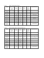
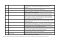
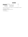
P/N 8514-197-001PR STACK EXPRESS 30 LB (13kg) CAPACITY COMPUTER CONTROL OPL WASHER DEXTER LAUNDRY, INC. OWNER'S BOOKLET INSTALLATION & OPERATION INSTRUCTIONS Please read this information and retain for reference. WARNING - THIS WASHER IS EQUIPPED WITH DEVICES AND FEATURES RELATING TO ITS SAFE OPERATION. TO AVOID INJURY OR ELECTRICAL SHOCK, DO NOT PERFORM ANY SERVICING UNLESS QUALIFIED TO DO SO. IT IS THE RESPONSIBILITY OF THE OWNER TO CHECK THIS EQUIPMENT ON A FREQUENT BASIS TO ASSURE ITS SAFE OPERATION. A machine should not be allowed to operate if any of the following occur: - Excessively high water level. - If machine is not connected to a properly grounded circuit. - If the door does not remain securely locked during the entire cycle. - Vibration or shaking from an inadequate mounting or foundation. WARNING - FOR SAFETY 1. 2. 3. 4. 5. 6. Always shut off power and water supply before servicing. Do not overload the washer. Do not open door when cylinder is in motion or it contains water. Do not bypass any safety devices of this washer. Do not use volatile or flammable substances in or near this washer. Keep all panels in place. They protect against shock and injury and add rigidity to the washer. PREVENTIVE MAINTENANCE REQUIREMENTS DAILY - Check that the loading door remains securely locked and cannot be opened during the entire cycle. - Check the water connections for leaks. - Clean the top and sides of the cabinet to remove residue. - Clean the soap dispenser and lid and check that all dispenser mounting screws are in-place and tight. - Check the drain valve for leaking and that it opens properly. - Check the loading door for leaks. Clean the door seal of all foreign matter. - Leave the loading door open to aerate the washer when not in use. QUARTERLY - Make sure the washer is inoperative by switching off the main power supply. - Check the V-belts for wear and proper tension. - Clean lint and other foreign matter from around motor. - Check all water connections for leaks. - Wipe and clean the inside of the washer and check that all electrical components are free of moisture and dust. - Remove and clean water inlet hose filters. Replace if necessary. - Check anchor bolts - retighten if necessary IMPORTANT: Replace any and all panels that were removed to perform daily and/or quarterly maintenance. MODE LIGHTS FLUSH WASH CYCLE PRE WASH WASH RINSE FINAL RINSE WASHER INSTRUCTIONS 1 Load clothes, latch door securely. 2 Put detergent and fabric softener, if required, into dispenser on front of machine (see diagram at right). 3 Select desired wash CYCLE with 4 Press START button. 5 If bleach is required, add when ADD BLEACH light comes on. DISPENSER and buttons. Door locks when machine starts, and remains locked until cycle is completed. If power is interrupted, there will be a 2 to 3 minute delay before the door can be opened. SPIN Add fabric softener. (Optional) Add Bleach Add detergent 30 LB STACK EXPRESS WASHER/DRYER DEXTER LAUNDRY, INC. INSTALLATION INSTRUCTIONS This washer may have been purchased as part of a stacked washer/dryer. In addition to thesr instructions, please also refer to the installation instructions that accompany the dryer when installing this product. All washers must be installed in accordance with all local, state and national building, electrical, plumbing and other codes in effect in the area. WARNING - THESE INSTALLATION AND SERVICING INSTRUCTIONS ARE FOR USE BY QUALIFIED PERSONNEL ONLY. TO AVOID INJURY AND ELECTRICAL SHOCK DO NOT PERFORM ANY SERVICING OTHER THAN THAT CONTAINED IN THE OPERATING INSTRUCTIONS, UNLESS QUALIFIED. FOUNDATION REQUIREMENTS WARNING: This machine is designed for use on or over bare concrete floor - not to be used above combustible flooring. The washer must be securely bolted and grouted to a substantial concrete floor, or mounted and grouted upon a suitable base, which is in turn, securely bolted and grouted to a substantial concrete floor. CARE MUST BE STRESSED WITH ALL FOUNDATION WORK TO INSURE A STABLE UNIT INSTALLATION, ELIMINATING POSSIBILITIES OF EXCESSIVE VIBRATION. All installations must be made on sound concrete floors, 6 inches (152 mm) or thicker. Anchor bolts or expansion anchors must be of a quality grade and a minimum of 5/8-inch (16 mm) diameter. MOUNTING A concrete pedestal or steel-mounting base that elevates the machine approximately 6 inches (152 mm) above the floor level is recommended to provide easy access to the loading door. Allow a minimum of 24 inches (610mm) of clearance behind the rear of the machine, to provide access for motor removal. Refer to Fig. 1-1 and 1-2 for machine bolt-down dimensions. If an elevated concrete pedestal is desired, it should be embedded into the existing floor. Anchor bolts should be 5/8" x 8" (16 mm x 200 mm), grade 8 or better, headed by a 4 inch (10 cm) square fish plate and should protrude 1 7/8 inches (48 mm) above the finished surface of the pedestal. EXPANSION ANCHORS ARE NOT RECOMMENDED FOR USE IN CONCRETE PEDESTALS, BECAUSE THE ANCHORS ARE TOO CLOSE TO AN EDGE, CAUSING IT TO BREAK OUT. (See Fig. 1-1 and 1-3.) PLUMBING Water supply hoses are furnished with each machine. Separate hot and cold water lines must be provided, maintaining 30 P.S.I . (207 kPa) to 120 P.S.I. (827 kPa) water flow pressure. A 140F (60C) degree hot water supply is recommended for best washing results. DRAIN The drain outlet tube at the rear of the machine is 3 inches (76 mm) in diameter. Any drain hose used must be lower than the drain valve to assure proper draining. ELECTRICAL 208-240V/1PH/50/60HZ OR 208-240/3PH/60HZ WARNING SHUT OFF POWER AND WATER BEFORE OPENING ANY SERVICE PANELS. This Dexter washing machine is intended to be a permanently installed appliance. No power cord is provided. The machine should be connected to an individual branch circuit not shared by lighting or other equipment. Where required, a means for disconnection with a contact separation distance of at least 3mm must be provided. The connection should be sheathed in liquid-tight flexible conduit, or equivalent, with conductors of the proper size and insulation. TO MAKE ELECTRICAL CONNECTIONS: Disconnect all power to the washer. Remove screw and lift out the cover located in the upper left corner of the machine (as viewed from the back). If power is 208-240-3PH-60Hz, connect L1, L2, L3 and ground. If there is a high leg it must be connected to L3. If power is 208-240-1PH-50/60Hz, connect L1, L2 (L1, N for 50Hz) and Ground. NOTE: It is important that the grounding screw next to the power terminal block TB-1 be connected to a good external ground. FUSING REQUIREMENTS: SINGLE- or THREE -PHASE POWER - 15 AMP TIME-DELAY (DUAL ELEMENT) FUSE (or equivalent circuit breaker) CONTROLS TRANSFORMER The controls transformer is mounted at the back of the control trough and has two voltage range settings. One terminal is provided for the range of 208 to 220 volts and the other is for the range of 221 to 240 volts. Make sure the transformer is wired to match the intended supply voltage. INJECTION SOURCE DETAILS The washer control may be programmed to send 120V (60Hz) or 24V (50 Hz) output signals for a chemical injection system. The signals are not intended as a power source and must be limited to less than 100 milliamps of current. There is a separate terminal block for connection of the external injection signals. For the injection sources, program codes 0 through 6 are as shown in the table below. Dexter Recommended Connections Controller Programmed Signals Injection Terminal Block Circuits Detergent 1 A Bleach 2 B Starch 3 C Sour/Softener 4 D 5 A and B 6 C and D 0 None CHECKOUT After all mounting, plumbing and electrical work is completed, the washer should be run through a cycle and checked for water leaks and proper functioning. SPECIFICATONS MODEL CAPACITY STACK WASHER/DRYER 30LB EXPRESS WASHER 30LBS/4 CUBIC FT. (13.6 kg/113 L) CYLINDER SIZE 25” DIA X 14 1/8” DEEP (63.5cm X 36cm) ELECTRICAL 208-240 VAC, 60 HZ, 1 OR 3 PHASE OR 208-240 VAC, 50HZ, 1 PHASE DRIVE SYSTEM SOFT START REVERSING INVERTER DRIVE, 2 HP MOTOR WASH SPEED 50 RPM INTERMEDIATE EXTRACT 411 RPM (60 G’S) FINAL EXTRACT SZ MODEL - 750 RPM (200 G’S) ST MODEL - 532 RPM (100 G’S) MACHINE CONTROL PROGRAMMABLE COMPUTER WITH 6 STANDARD CYCLES. WATER INLET 2 SOLENOID OPERATED VALVES FLOW RATE: 9 GAL/MIN (34L/MIN) EACH, 30-120 PSI (207kPa827kPa) DRAIN VALVE 3” (76mm) DIAMETER STARTING THE WASHER A. Load the clothes into the cylinder and latch the door securely. Be sure clothing does not get caught between the door gasket and tub front when closing the door. Maximum load is 30 pounds (13.6kg) clothes, dry weight. Do not load the washer with more than 30 lbs. (13.6kg). B. Select the appropriate cycle number (1 through 6) using for the load being washed. See the cycle descriptions in the programming section. Use the UP and DOWN keys to change the cycle number. C. If not using a chemical injection system, add low-sudsing powdered detergent into the “detergent” compartment of the automatic dispenser on the top of the washer. If desired add fabric softener to the “fabric softener” compartment. Use the amount of fabric softener as recommended by the manufacturer. If liquid wash products are used in the “detergent” compartment, they must be added at the beginning of the wash cycle. If the machine is set for pre-wash, washing products can be added to the round opening of the dispenser or put in with the clothes when loading the cylinder before starting the machine. D. Press START. The display will go blank for a moment and then display the cycle time in minutes. The clothes door will lock and remain locked until the end of the cycle. END OF CYCLE When the cycle is complete the “on” light will go off. The door can now be opened and the clothes load removed. Leave the clothes door open when the machine is not in use. SAFETY DOOR LOCK This machine is equipped with a Safety Door Lock that prevents opening the door if the power is interrupted, until it is safe to do so. If power failure occurs or if power is interrupted during maintenance it will be necessary to wait 2 to 3 minutes before the door can be opened. PROGRAMMING INSTRUCTIONS: Programming can be accomplished manually using the machine controls or by connecting to the machine control using a PDA (personal digital assistant). For instructions on using a PDA with this washer control, please contact your local Dexter distributor. Please read below for manual programming instructions. The keypad layout for the washer control is shown above. WASH CYCLE PROGRAMMING: 1. Turn on the power to the washer. 2. Turn the Run/Program key to the Program position. Display will show “C O” and the “ADD BLEACH” will blink and will continue to blink during the programming mode. 3. Press the “DOWN” or “UP” buttons to select which cycle to alter. When the desired cycle number is displayed, press “START”. 4. The display should now show a “b”. The “b” and the cycle indicator lights indicate which bath is being selected to alter. Press the “UP” and “DOWN” buttons to select a bath to change and then press “START”. The indicator lights are shown below. FLUSH PRE WASH WASH RINSE FINAL RINSE SPIN When “RINSE” is selected, “b r1” through “b r4” may be selected. There may be multiple rinses that are indicated by r1, r2, r3 and r4. 5. Each bath can be programmed with the following options. Use the “DOWN” and “UP” keys to select the desired setting and the “START” key to move to the next option. DISPLAY FUNCTION OPTIONS Ct ** t ** Tumble Time Water Temperature L ** dF * S ** IS * Water Level Type of Fill Spin Time Injection Source Two-digit amount of time in minutes. HH for hot, CH for warm, CC for cold and EE for no water. Lo for low, Hl for high. d for delayed fill, t for timed fill.1 Two-digit amount of time in minutes. Single digit code indicating injector signal(s).2 1 A delayed fill will pause the time count until the selected level is reached. A timed fill will only fill for a predetermined amount of time. 2 Codes for injections sources are defined at the end of the programming section. When the No Water bath is selected, the electronic controller prohibits injection signals. The programmed injection source value is ignored. To exit the programming of a bath, press the “STOP” button once and use the “UP” and “DOWN” keys select another bath. Press the “STOP” button again to select a different cycle to change. To end programming, turn the key to “RUN” position Note: The Wash Cycle programming mode will automatically exit and return to the Idle mode if no buttons are pushed for one minute. WASHER CYCLE PARAMETER RANGES The range of each cycle parameter is shown below: Cycle Time 0 to 15 minutes for Prewash, Wash, Rinse1, 2, 3 and 4 1 to 15 minutes for Final Rinse For the bathes that can, if the time is set to zero, then the bath will be eliminated from the cycle. Water Temperature HH – hot, CH – warm, CC – cold, EE – no water Water Level HI – high, LO – low Delay Fill The selections are “d” for delay the bath time until water level is reached or “t” for decrement bath time during the fill. Spin Time 0 to 10 minutes for Prewash, Wash, Rinse, 2, 3 and 4 1 to 10 minutes for Final Spin Injection Source 0 to 6 Cycle 1 Sheets & Pillowcases (Health Care) Bath Bath Cycle Time (min.) Water Temp. Water Level Delay Fill Spin Time (min.) Injection Source Flush 3 CH HI d Prewash 2 CH HI d Wash 7 HH LO d 1 (Detergent) Rinse 1 7 HH LO d 2 (Bleach) Rinse 2 2 CH HI d Rinse 3 2 CH HI d 4 CH LO d 4 4 (Sour/Soft) Spin Time (min.) Injection Source 1 Rinse 4 Final Rinse Cycle 2 Towels / Pads / Diapers (Health Care) Bath Bath Cycle Time (min.) Water Temp. Water Level Delay Fill Flush 3 CH HI d Prewash 2 CH HI d Wash 7 HH LO d Rinse 1 1 HH HI d Rinse 2 7 HH LO d Rinse 3 2 CH HI d Rinse 4 2 CH HI d Final Rinse 4 CH LO d 1 (Detergent) 2 (Bleach) 1 5 4 (Sour/Soft) Cycle 3 Bath White Towels (Hotel / Motel) Bath Cycle Time (min.) Water Temp. Water Level Delay Fill Wash 7 HH LO d Rinse 1 1 HH HI d Rinse 2 7 HH LO d Rinse 3 2 CH HI d Rinse 4 2 CH HI d Final Rinse 4 CH LO d Spin Time (min.) Injection Source Flush Prewash Cycle 4 1 (Detergent) 2 (Bleach) 1 5 4 (Sour/Soft) Spin Time (min.) Injection Source Guest Laundry (Hotel / Motel or Health Care) Bath Bath Cycle Time (min.) Water Temp. Water Level Delay Fill Flush 3 CH HI d Wash 7 HH LO d Rinse 1 2 HH HI d Rinse 2 2 CH HI d Rinse 3 2 CH HI d 4 CH LO d Prewash 5 (Detergent/Bleach) Rinse 4 Final Rinse 4 4 (Sour/Soft) Cycle 5 Rags & Mops (Hotel / Motel) Bath Bath Cycle Time (min.) Water Temp. Water Level Delay Fill Flush 3 CH HI d Prewash 2 CH HI d Wash 2 CH HI d Rinse 1 7 HH LO d Rinse 2 2 HH HI d Rinse 3 7 HH LO d Rinse 4 2 CH HI d 1 Final Rinse 2 CH LO d 5 Spin Time (min.) Cycle 6 Spin Time (min.) Injection Source 1 (Detergent) 2 (Bleach) Colored Cotton Linen (Food & Beverage) Bath Bath Cycle Time (min.) Water Temp. Water Level Delay Fill Injection Source Flush 2 CH HI d Wash 10 HH LO d 1 (Detergent) Rinse 1 7 HH LO d 2 (Bleach) Rinse 2 2 CH HI d Rinse 3 2 CH HI d 4 CH LO d Prewash 1 Rinse 4 Final Rinse 4 6 (Sour/Starch) RAPID ADVANCE MODE To enter the Rapid Advance mode, turn the key counter-clockwise (CCW). The Rapid Advance setting is not marked next to the key, but turning the key CCW until it stops selects this mode. The Rapid Advance mode can be entered from either the Idle mode or during the cycle. If the cycle has not yet started, press the “START” button. To rapid advance to the next step in the wash cycle, push both the “UP” and “START” buttons at the same time. The display will show an “Ad” (advance) in the display. The washer will advance to the next bath segment. The water will drain before the advance will occur and the time displayed may not be accurate. Notes: The indicator lights will show to which segment the cycle has been advanced. The cycle will continue in rapid advance mode even if the key is turned to “RUN” and/or removed. Rapid advance cannot skip the final 1-minute tumble of the cycle, and the door lock may remain activated for a couple minutes after the cycle has been completed. The chemical injection signals will not operate in Rapid Advance mode. To end the cycle and exit the Rapid Advance mode without waiting for the time to count down, push and hold the STOP button for 5 seconds or more. INJECTION SOURCE DETAILS The washer control may be programmed to send output signals for a chemical injection system. There is a separate terminal block for connection of the external injection signals. For the injection sources, program codes 0 through 6 are as shown in the table below. See the ELECTRICAL section for more information. Dexter Recommended Connections Controller Programmed Signals Injection Terminal Block Circuits Detergent 1 A Bleach 2 B Starch 3 C Sour/Softener 4 D 5 A and B 6 C and D 0 None WASHER ERROR CODES Fault # (F #) Description Customer Action 1 The door failed to close and lock or the door failed to remain locked after three tries of latching the door and starting during the cycle. The washer tub does not fill with water within 7 minutes. The wash cycle will continue. The F 2 will flash three times, then wait for 30 seconds. The error will clear at the end of the cycle. Memory error in controller. Turn off the power to the washer. Check wire connections to door /lock switches. Check wire connections from switches to controller. If necessary the door lock mechanism should be adjusted by a qualified person. Turn on the power to the washer. (See Note) Turn of the power to the washer. Check the operation of the water valves. Check the incoming water pressure. Check for blocked or restricted water flow. Check to ensure the drain valve is functioning properly. Turn on the power to the washer. (See Note) 2 3 4 5 6 7 8 9 10 Turn off the power to the washer. Wait one minute. Turn power back on to the washer. If the problem returns, clear the fault with the Palm. If the problem returns again, replace the washer controller. Washer controller communication error Turn off the power to the washer. Wait one minute. Turn power back on to the washer. If the problem returns, replace the washer controller. Pressure Switch error ( only OPL )- when the Turn off the power to the washer. Replace the pressure switch. Turn on power to the washer. high level sensor indicates full but the lower one (See Note) indicates empty. The wash cycle will continue. The F 5 will flash three times, then wait for 30 seconds. The error will clear at the end of the cycle. Wrong washer size for drive type. Turn off the power to the washer. Check to ensure all the harnesses are properly connected to the controller. Check to ensure the drive horsepower is proper for this size of washer. Turn on power to the washer. (See Note) If problem reappears, contact your Dexter representative. Wrong size drive installed Turn off the power to the washer. Check to ensure all the harnesses are properly connected to the controller. Check to ensure the drive horsepower is proper for this size of washer. Contact your Dexter representative. The washer tub does not empty within 7 Turn off the power to the washer. Check to ensure the drain valve is operating properly. minutes. The wash cycle will continue. The F 8 Check to ensure the pressure switch tube is clear of blockage. Check to ensure the pressure will flash three times, then wait for 30 seconds. switch is operating proper. Correct any located problems. Turn on power to the washer. (See The error will clear at the end of the cycle. Note) The washer tub does not reach the spin target Turn off the power to the washer. Inspect the washer to ensure the tub spins freely. If frequency within 200 seconds. The wash cycle restricted, then clear the blockage. Test washer. If tub spins freely, the drive needs to be will continue. The F 9 will flash three times, replaced. then wait for 30 seconds. The error will clear at the end of the cycle. After a spin the washer tub does not stop within Turn off the power to the washer. Inspect the braking resistors and the connecting wiring to 150 seconds. the drive braking resistors mounted in the top of the washer. If the resistors and wiring is correct, then replace the drive. 11 12 13 14 15 16 17 18 19 20 21 The drive size setting has changed. Turn off the power to the washer. Check to ensure all the harnesses are properly connected to the controller. Check to ensure the drive horsepower is proper for this size of washer. Turn on power to the washer. (See Note) If problem reappears, contact your Dexter representative. Washer controller internal error Turn off the power to the washer. Wait one minute. Turn on the power to the washer. (See Note) If problem reappears, contact your Dexter representative. The control cannot communicate with the drive Turn the power off to the washer. Check the data cable between the controller and the drive. If no problem is observed, turn on power to the washer and test. (See Note) If problem reappears, contact your Dexter representative. Over-current on the drive or motor. Turn the power off to the washer. Check the washer motor to ensure it turns freely. Check the wiring connections to the drive and motor. If no problem is observed, turn on power to the washer and test. (See Note) If problem reappears, contact your Dexter representative. Over-voltage on the drive or motor. Turn the power off to the washer. Check the washer motor to ensure it turns freely. Check the wiring connections to the drive, braking resistors and motor. Measure incoming line voltage. If no problem is observed, turn on power to the washer and test. (See Note) If problem reappears, contact your Dexter representative. Overheating of the drive Turn the power off to the washer. Allow the drive to cool. Check the cooling fins of the drive to ensure proper airflow. Check the wiring to the drive including the fan wiring. If no problem is observed, turn on power to the washer and test. (See Note) If problem reappears, contact your Dexter representative. Overload of the drive or motor Turn the power off to the washer. Check the washer motor to ensure it turns freely. Check the wiring connections to the drive and motor. If no problem is observed, turn on power to the washer and test. (See Note) If problem reappears, contact your Dexter representative. Ground Fault to the drive Turn the power off to the washer. Check the wiring connections to the drive and motor. Check the ground wiring of the drive, motor and incoming connection to ensure a proper ground is present. If no problem is found, contact your Dexter representative. Low Voltage to the drive Turn the power off to the washer. Check the wiring connections to the drive and motor. If no problem is observed, turn on power to the washer and test. (See Note) Measure the incoming line voltage. If problem reappears, contact your Dexter representative. Internal drive error Turn the power off to the washer. Wait one minute. Turn the power on to the washer. (See Note) If problem reappears, contact your Dexter representative. Data error on communications between the Turn the power off to the washer. Check the data cable between the controller and the drive. controller and drive If no problem is observed, turn on power to the washer and test. (See Note) If problem reappears, contact your Dexter representative. Note: Whenever power is turned off to the washer, it must remain off for one minute. The washer will not operate properly if this is not done. ACCESSORIES INSTALLATION: (Furnished) 9990-027-011 Hose, Water Supply 8641-242-000 Washer, Inlet Hose 9565-003-001 Strainer, Inlet Hose QTY. 2 2 4 Contact your distributor or Dexter Laundry, Inc. if a steel-mounting base is required. © 2010, Dexter Laundry, Inc. 2211 West Grimes, Fairfield, IA 52556 U.S.A. 1-800-524-2954 www.dexterlaundry.com