1
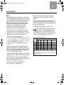
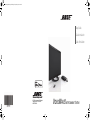
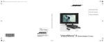
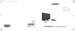
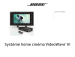
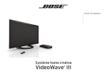
VideoWave2 Setup Guide Covers_AIM.fm Page 1 Wednesday, January 25, 2012 11:34 AM
Setup Guide
Guía de instalación
Guide d’installation
©2012 Bose Corporation, The Mountain,
Framingham, MA 01701-9168 USA
AM352276 Rev.00
®
VIDEOWAVE II ENTERTAINMENT SYSTEM
00.Marley_Setup.book Page 2 Tuesday, January 10, 2012 8:47 AM
Tab 8, 16
Tab 7, 15
Tab 6, 14
Tab 5, 13
Tab 4, 12
Tab 3, 11
Tab 2, 10
English
SAFETY INFORMATION
Please read this guide
Please take the time to follow the instructions in this setup guide
carefully. They will help you set up and operate your system
properly and enjoy its advanced features. Please save all safety
and operating instructions, including this guide, for
future reference.
All Bose products must be used in accordance with local, state,
and federal law, and industry standards.
• Do not place any naked flame sources, such as lighted
candles, on or near the apparatus.
• Keep the remote control batteries away from children. They may
cause a fire or chemical burn if mishandled. Do not recharge,
disassemble, heat above 100ºC (212ºF), or incinerate. Dispose
of used batteries promptly. Replace only with batteries of the
correct type and model number.
Please dispose of used batteries properly,
following any local regulations. Do not
incinerate.
• Contains small parts that may be a choking hazard.
Not suitable for children under age 3.
The lightning flash with arrowhead symbol within an
equilateral triangle alerts the user to the presence of
uninsulated, dangerous voltage within the system
enclosure that may be of sufficient magnitude to constitute
a risk of electric shock.
The exclamation point within an equilateral triangle alerts
the user to the presence of important operating and
maintenance instructions in this guide.
WARNINGS:
• To reduce the risk of fire or electrical shock, do not expose the
product to rain or moisture.
• Do not expose this apparatus to dripping or splashing, and do not
place objects filled with liquids, such as vases, on or near the
apparatus. As with any electronic products, use care not to spill
liquids into any part of the system. Liquids can cause a failure and/
or a fire hazard.
• Never place the equipment on an unstable surface. The
equipment may fall, causing serious personal injury or death.
Many injuries, particularly to children, can be avoided by taking
simple precautions such as:
– Only using furniture that can safely support the equipment.
– Ensuring the equipment is not overhanging the edge of the
supporting furniture.
– Not placing the equipment on furniture (for example, cupboards
or bookcases) without appropriately anchoring both the
furniture and the equipment to a wall.
– Not placing toys or other items on top of the equipment.
– Not standing the equipment on cloth or other materials placed
between the equipment and supporting furniture.
– Educating children about the dangers of playing with the
equipment and climbing on furniture to reach the equipment.
©2012 Bose Corporation. No part of this work may be reproduced, modified, distributed, or otherwise used without prior written permission.
2
00.Marley_Setup.book Page 3 Tuesday, January 10, 2012 8:47 AM
English
Tab 2, 10
Tab 3, 11
Tab4, 12
Tab 6, 14
Tab 5, 13
Tab 7, 15
Tab 8,16
SAFETY INFORMATION
• Allowing children to push, pull, or climb on the monitor may cause
it to tip over, possibly resulting in personal injury or death.
– For safety and greater stability, installation of the included
anti-tip straps is recommended.
– Be sure to install both anti-tip straps according to the
instructions on page 11.
• If wall-mounting the monitor, follow the wall bracket manufacturer’s
instructions and the guidelines provided here and on page 13.
Unsafe mounting of any heavy load can result in serious injury and
property damage.
– Use only an agency-approved wall-mount bracket capable of
supporting a 150 lb. (68 kg) product.
– Make sure the wall bracket is installed according to all
applicable building codes.
– If you doubt your ability to safely wall-mount this product,
contact a professional installer for help.
• Long-term exposure to loud audio may cause hearing damage.
It is best to avoid extreme volume when using the system with or
without headphones, especially for extended periods.
CAUTIONS:
• Make no modifications to the system or accessories.
Unauthorized alterations may compromise safety, regulatory
compliance, and system performance, and may void the warranty.
• Due to ventilation requirements, do not place the monitor in a
confined space such as in a wall cavity or in an enclosed cabinet.
• Do not block any of the ventilation openings on the rear panel of
the monitor. These openings provide the necessary ventilation to
ensure reliable operation and to prevent overheating.
• Do not place the monitor near or over a source of heat, such as a
fireplace, or in direct sunlight.
Notes:
• Where the mains plug or appliance coupler is used as the
disconnect device, such disconnect device shall remain readily
operable.
• The product must be used indoors. It is neither designed nor
tested for use outdoors, in recreation vehicles, or on boats.
• This product is intended to be used only with the power supply
provided.
• Product labels are located on the bottom of the control console,
on the back of the monitor, and inside the battery compartment
door of the remote control.
IMPORTANT SAFETY INSTRUCTIONS
1.
2.
3.
4.
5.
6.
7.
Read these instructions.
Keep these instructions.
Heed all warnings.
Follow all instructions.
Do not use this apparatus near water.
Clean only with a dry cloth.
Do not block any ventilation openings. Install in accordance
with the manufacturer’s instructions.
8. Do not install near any heat sources such as radiators, heat
registers, stoves, or other apparatus (including amplifiers)
that produce heat.
9. Protect the power cord from being walked on or pinched
particularly at plugs, convenience receptacles, and the point
where they exit from the apparatus.
10. Only use attachments/accessories specified by the
manufacturer.
11. Unplug this apparatus during lightning storms or when
unused for long periods of time.
12. Refer all servicing to qualified personnel. Servicing is
required when the apparatus has been damaged in a way,
such as power-supply cord or plug is damaged, liquid has
been spilled or objects have fallen into the apparatus, the
apparatus has been exposed to rain or moisture, does not
operate normally, or has been dropped.
3
00.Marley_Setup.book Page 4 Tuesday, January 10, 2012 8:47 AM
Tab 8, 16
Tab 7, 15
Tab 6, 14
Tab 5, 13
Tab 4, 12
Tab 3, 11
Tab 2, 10
English
SAFETY INFORMATION
Notice
This equipment has been tested and found to comply with the
limits for a Class B digital device, pursuant to Part 15 of the FCC
rules. These limits are designed to provide reasonable protection
against harmful interference in a residential installation. This
equipment generates, uses, and can radiate radio frequency
energy and, if not installed and used in accordance with the
instructions, may cause harmful interference to radio
communications. However, there is no guarantee that
interference will not occur in a particular installation.
If this equipment does cause harmful interference to radio or
television reception, which can be determined by turning the
equipment off and on, you are encouraged to try to correct the
interference by one or more of the following measures:
• Reorient or relocate the receiving antenna.
• Increase the separation between the equipment and receiver.
• Connect the equipment to an outlet on a different circuit than
the one to which the receiver is connected.
• Consult the dealer or an experienced radio/TV technician
for help.
These devices comply with FCC and Industry Canada RF
radiation exposure limits set forth for general population. They
must not be co-located or be operating in conjunction with any
other antennas or transmitters. Both the console and remote
control contain 2.4 GHz intentional radiators.
These devices comply with Industry Canada licence-exempt RSS
standard(s). Operation is subject to the following two conditions:
(1) These devices may not cause interference, and (2) these
devices must accept any interference, including interference that
may cause undesired operation of the device.
Remote control output power: 2.3 mW @ 2.4 GHz
Console output power: 1.5 mW @ 2.4 GHz
4
Changes or modifications not expressly approved by Bose
Corporation could void the user’s authority to operate this
equipment.
Operation is subject to the following two conditions: (1) This
device may not cause harmful interference, and (2) this device
must accept any interference received, including interference that
may cause undesired operation.
The temperature range of this product is 0° C to +55° C.
Bose Corporation hereby declares that this product is in
compliance with the essential requirements and other
relevant provisions of Directive 1999/5/EC and all other
applicable EU directive requirements. The complete declaration of
conformity can be found at: www.Bose.com/compliance.
Names and Contents of Toxic or Hazardous Substances or Elements
Toxic or Hazardous Substances and Elements
Lead
(Pb)
Mercury
(Hg)
Cadmium
(Cd)
Hexavalent
(CR(VI))
Polybrominated
Biphenyl (PBB)
Polybrominated
diphenylether (PBDE)
PCBs
X
0
0
0
0
0
Metal parts
X
0
0
0
0
0
Plastic parts
0
0
0
0
0
0
Speakers
X
0
0
0
0
0
Cables
X
0
0
0
0
0
Part Name
0: Indicates that this toxic or hazardous substance contained in all of the homogeneous materials for this part is below the limit
requirement in SJ/T 11363-2006.
X: Indicates that this toxic or hazardous substance contained in at least one of the homogeneous materials used for this part is
above the limit requirement in SJ/T 11363-2006.
00.Marley_Setup.book Page 5 Tuesday, January 10, 2012 8:47 AM
English
TAB 2
TAB 3
TAB 4
WELCOME
Product overview . . . . . . . . . . . . . . . . . . . . . . . . .
The setup process . . . . . . . . . . . . . . . . . . . . . . . .
PHYSICAL SETUP
Monitor placement and connections . . . . . . . . . .
Monitor placement recommendations . . . . . . .
Placing the monitor with stand . . . . . . . . . . . . .
Installing the anti-tip straps . . . . . . . . . . . . . . .
Wall-mounting the monitor . . . . . . . . . . . . . . . .
Control console placement and connections . . .
INTERACTIVE SETUP
Starting the system . . . . . . . . . . . . . . . . . . . . . . .
If you have setup problems . . . . . . . . . . . . . . . . .
Contacting customer service . . . . . . . . . . . . . . . .
TAB 5
TAB 6
TAB 7
TAB 8
7
7
7
8
8
8
9
11
13
15
17
17
19
19
5
00.Marley_Setup.book Page 6 Tuesday, January 10, 2012 8:47 AM
TAB 8
6
TAB 7
TAB 6
TAB 5
TAB 4
TAB 3
TAB 2
English
00.Marley_Setup.book Page 7 Tuesday, January 10, 2012 8:47 AM
English
Tab 2, 10
Tab 3, 11
Tab4, 12
Tab 6, 14
Tab 5, 13
Tab 7, 15
Tab 8,16
WELCOME
Thank you
The setup process
®
®
Thank you for purchasing the Bose VideoWave
entertainment system. This guide provides you with
step-by-step instructions for setting up your new
entertainment system.
Note: Professional installation is recommended.
Product overview
The VideoWave system features a monitor and stand,
and comes with a control console, a remote control,
and a dock compatible with iPod and iPhone. The
control console connects to the monitor using a single
cable. Each of your A/V devices connects to the back
of the control console.
Control
console
Bose click pad
remote control
Stand
The smaller box contains the control console, monitor
stand, screws, and system parts. Inside are two boxes
labeled 11 and 2 . These boxes contain the system
parts that are used in different stages of the setup
process.
Carefully unpack each item as you proceed through the
setup. If an item is damaged, do not attempt to use it.
Notify Bose or your authorized Bose dealer
immediately. For Bose contact information, see the
address sheet included in the monitor stand box.
There are two parts to the setup process:
• Physical setup – This part of the setup includes
placing the monitor and control console and making
system connections. The items used in this stage are
the monitor, the stand, the parts located in Box 11,
and the control console.
• Interactive setup – This part begins when you turn
on the system and start following the on-screen
instructions provided by the Unify intelligent
integration system. This proprietary technology will
help you complete the setup, showing you the right
inputs and best connection options, and will even
verify that you've done it correctly. The items used for
this stage are located in Box 2 .
®
Monitor
Dock for iPod
and iPhone
Your VideoWave entertainment system is packed in two
boxes. The large rectangular box contains the monitor.
7
00.Marley_Setup.book Page 8 Tuesday, January 10, 2012 8:47 AM
Tab 8, 16
Tab 7, 15
Tab 6, 14
Tab 5, 13
Tab 4, 12
Tab 3, 11
Tab 2, 10
English
PHYSICAL SETUP
Monitor placement
and connections
The monitor can be placed on furniture using the
attached stand or it can be mounted on a wall.
WARNING: The monitor weighs about 119 lbs. (59 kg).
To prevent personal injury, a two-person lift is required.
CAUTION: DO NOT mount or place the monitor in a
recessed area or cabinet. This can block the ventilation
openings and affect the acoustic performance.
CAUTION: Do not place the monitor near or over a
source of heat, such as a fireplace. Any damage that may
occur to your monitor as a result of placing it over a
fireplace will not be covered by the limited warranty on
your VideoWave entertainment system.
®
The following recommendations are provided to help
you place the monitor in the best possible location:
• The back of the monitor should be approximately
1-4 in. (2.5-10.0 cm) from a wall.
• You should try to allow 3-10 ft. (0.9-3.0 m) between
the monitor and the side walls of the room.
• Allow at least 8 in. (20 cm) of clearance from the top
of the monitor to any surface above (such as a shelf)
to allow for proper ventilation and acoustic
performance.
• The area between the side walls and the monitor
should be free of as many objects as possible that
would block the sound, such as tall bookcases and
storage cabinets.
• To enjoy the best audio and video performance, try to
have the vertical center of the screen at eye level
when seated.
1 - 4 in. (2.5 - 10.0 cm)
Monitor placement recommendations
Much like a live performance in a concert hall, the
VideoWave entertainment system relies on the
reflective surfaces of the room to deliver a spacious
home theater experience. The system features
ADAPTiQ audio calibration technology, which
customizes the sound during setup based on where
the system is positioned, as well as the size, shape,
and furnishings of the room it is in.
3 - 10 ft.
(0.9 - 3.0 m)
®
Direct
sound
3 - 10 ft.
(0.9 - 3.0 m)
®
Side
reflected
sound
Side
reflected
sound
LISTENER
8
00.Marley_Setup.book Page 9 Tuesday, January 10, 2012 8:47 AM
English
Tab 2, 10
Tab 3, 11
Tab4, 12
Tab 6, 14
Tab 5, 13
Tab 7, 15
Tab 8,16
PHYSICAL SETUP
Here is what you need from Box 1:
Placing the monitor with stand
Before you place the monitor, you must attach the stand.
11
1. Unpack the stand, screws, and monitor.
2. Lower the monitor onto the stand, carefully lining
up the holes in the bottom of the monitor with the
supports on the stand.
Monitor AC power cord
Anti-tip straps
Monitor cable*
WARNING: The monitor weighs about 119 lbs.
(54 kg). To prevent personal injury, a two-person lift
is required.
Anti-tip strap
screws (2)
*Not rated for in-wall use. In-wall monitor cables are available from
Bose or a Bose authorized dealer.
®
You also need the stand, screws, and wrench:
Hex wrench
Monitor
support
Monitor
support
Stand screws (2)
Monitor stand
9
00.Marley_Setup.book Page 10 Tuesday, January 10, 2012 8:47 AM
Tab 8, 16
Tab 7, 15
Tab 6, 14
Tab 5, 13
Tab 4, 12
Tab 3, 11
Tab 2, 10
English
PHYSICAL SETUP
3. On the rear panel of the monitor, firmly pull out on
the bottom of the connector cover to remove it.
5. Place the monitor on a stable, flat surface capable
of supporting the combined weight of the stand
and the monitor (150 lbs.).
Connector
cover
Monitor
4. Insert the screws into the holes on the back of the
monitor and tighten using the provided 5/32 in.
(4 mm) hex wrench.
6. Attach the monitor cable and AC power cord to the
monitor as shown.
Monitor
cable
AC power
cord
10
00.Marley_Setup.book Page 11 Tuesday, January 10, 2012 8:47 AM
English
Tab 2, 10
Tab 3, 11
Tab4, 12
Tab 6, 14
Tab 5, 13
Tab 7, 15
Tab 8,16
PHYSICAL SETUP
7. Route both cords through the leg of the stand and
re-attach the connector cover.
Installing the anti-tip straps
It is important that you install both straps according to
the following instructions.
WARNING: Do not use the anti-tip straps for any
application other than the one specified in this setup
guide.
Leg of stand
CAUTION: If you are unsure of the construction methods
used in your home, or if you do not understand these
instructions or have any concerns or questions, please
contact a professional installer.
1. Using the provided 5/32 in. (4 mm) hex wrench,
remove the top two bolts from the rear panel of the
monitor as indicated.
8. Plug the AC power cord from the monitor into a live
AC (mains) outlet.
9. Go to “Control console placement and connections” on page 15 to continue the physical setup.
Bolts to
remove
CAUTION: Bose strongly recommends installing the
two included anti-tip straps that, when properly installed,
provide an extra measure of security in the event that the
monitor accidentally starts to tip over.
11
00.Marley_Setup.book Page 12 Tuesday, January 10, 2012 8:47 AM
Tab 8, 16
Tab 7, 15
Tab 6, 14
Tab 5, 13
Tab 4, 12
Tab 3, 11
Tab 2, 10
English
PHYSICAL SETUP
3. Locate the two wall studs closest to the straps.
Each strap should be attached to the wall stud
closest to it.
DO NOT attach both straps to the same stud.
min
CAUTION: The included screws are for use only into
wood-studded wall constructions with one-inch (max.)
drywall. For all other types of wall construction, please
contact a professional installer. Use caution to avoid any
electrical or plumbing lines running through the studs.
4. Hold the bracket on the end of each strap against
the wall above the tabletop. Hold the bracket a
minimum of 18 in. (46 cm) or maximum of 24 in.
(61 cm) above the tabletop. In the center of each
wall stud, mark the location of the two holes in the
bracket.
max
2. Using the same bolts, attach the two straps to the
back of the monitor as shown.
Tabletop
5. Using a 7/64 in. (3 mm) drill bit (not included), drill
four pilot holes.
6. Secure each bracket to the wall using two of the
provided screws.
12
00.Marley_Setup.book Page 13 Tuesday, January 10, 2012 8:47 AM
English
Tab 2, 10
Tab 3, 11
Tab4, 12
Tab 6, 14
Tab 5, 13
Tab 7, 15
Tab 8,16
PHYSICAL SETUP
7. Push monitor back to within 1-4 in. (2.5-10 cm)
from the wall.
Wall-mounting the monitor
®
The VideoWave system is compatible with any VESA
certified bracket that uses a 400 mm x 400 mm screw
pattern. The panel itself without the stand weighs
119 lbs. (59 kg), so the mount must be able to support
that weight. Articulating wall mounts are not optimal
because of the effect that changes in position might
have on the acoustics and are therefore not
recommended.
1. Remove the bag from the monitor.
1 - 4 in.
(2.5 - 10.0 cm)
2. On the rear panel of the monitor, firmly pull out on
the bottom of the connector cover (A) then pull
down (B) to remove it.
Tabletop
8. Tighten the straps to remove any slack between
the monitor and the wall.
9. Bundle the remaining length of the straps and
secure them out of reach behind the monitor.
B
A
13
00.Marley_Setup.book Page 14 Tuesday, January 10, 2012 8:47 AM
Tab 8, 16
Tab 7, 15
Tab 6, 14
Tab 5, 13
Tab 4, 12
Tab 3, 11
Tab 2, 10
English
PHYSICAL SETUP
3. Attach the monitor cable and AC power cord to the
monitor as shown.
4. Attach the wall-mounting brackets (not included)
to the wall and monitor according to the instructions included with the wall bracket.
5. Lift the monitor out of the packing.
Monitor cable
AC power
cord
Note: You do not need to re-attach the connector cover.
Hiding the cables behind the monitor may be easier with
the cover removed.
14
WARNING: The monitor weighs about 119 lbs. (59 kg).
To prevent personal injury, a two-person lift is required.
6. Attach the monitor to the wall according to the
instructions included with the wall bracket.
Note: If using an AC (mains) outlet that is on the wall
behind the monitor, be sure to plug in the power cord
before hanging the monitor.
00.Marley_Setup.book Page 15 Tuesday, January 10, 2012 8:47 AM
English
Tab 2, 10
Tab 3, 11
Tab4, 12
Tab 6, 14
Tab 5, 13
Tab 7, 15
Tab 8,16
PHYSICAL SETUP
Control console placement
and connections
Here is what you need from Box 1:
11
Power supply
Power supply
AC power cord
1. Place the control console on a flat, stable
surface near the monitor.
• Make sure the supplied monitor cable (3 m) can
reach from the console to the monitor.
• Until your system setup is complete and your
external devices are connected, it is helpful to
keep the control console positioned for easy
access to its rear connection panel.
CAUTION: If using the monitor on the stand, DO NOT
place the control console between the legs of the stand
or anywhere directly under the bottom edge of the
monitor. This will avoid blocking ventilation and audio
system openings in the product enclosure.
You also need the control console:
Monitor
Control console
Control
console
15
00.Marley_Setup.book Page 16 Tuesday, January 10, 2012 8:47 AM
Tab 8, 16
Tab 7, 15
Tab 6, 14
Tab 5, 13
Tab 4, 12
Tab 3, 11
Tab 2, 10
English
PHYSICAL SETUP
2. Plug the free end of the monitor cable into the
connector labeled A/V OUT to Monitor on the
control console.
3. Plug the power supply output cord into the control
console Power connector.
Control console
AC power cord
Power
Power supply
output cord
A/V OUT
to Monitor
Monitor
cable
Power
supply
4. Plug one end of an AC power cord into the power
supply. Make sure you push the plug in as far as it
can go.
5. Plug the other end of the power cord into a live
AC (mains) power outlet.
6. Go to “Interactive setup” on page 17 and follow the
instructions to start up the system.
16
00.Marley_Setup.book Page 17 Tuesday, January 10, 2012 8:47 AM
English
Tab 2, 10
Tab 3, 11
Tab4, 12
Tab 6, 14
Tab 5, 13
Tab 7, 15
Tab 8,16
INTERACTIVE SETUP
Starting the system
You are now ready to turn on your system and
complete the setup process using the Unify intelligent
integration system.
®
Here is what you need from Box 2:
Box 2 additional included items:
These are items you may need to connect A/V devices
to your system. When it is time to connect devices, the
Unify system will guide you in choosing the right cable.
2
2
TM
HDMI cable (2)
Component
video cable
Stereo audio
cable
®
Bose click pad remote
control with batteries
®
ADAPTiQ audio
calibration headset
Composite
video cable
Dock for iPod
and iPhone
IR emitter
cable
USB flash drive
17
00.Marley_Setup.book Page 18 Tuesday, January 10, 2012 8:47 AM
Tab 8, 16
Tab 7, 15
Tab 6, 14
Tab 5, 13
Tab 4, 12
Tab 3, 11
Tab 2, 10
English
INTERACTIVE SETUP
1. Press the power button ( ) on the control console.
The power light on the control console indicates
the startup status.
Note: When the system starts up, you will hear a start-up
tone, and on the monitor screen you will see the Bose
logo with a progress bar under it.
®
2. Slide the battery compartment cover off the back
of the remote control.
Battery compartment
cover
Power light
Status
Meaning
Red
Off
Blinking green
Starting up
Steady green
On and ready to use
Orange
Off and charging iPod or iPhone
Blinking yellow for 30
seconds after shutting
system down
Unify system setup was started, but is
incomplete
Slow blinking red while
system is off
Unify system setup is complete, but no
sources are present
Red blinking off every 5
seconds
Remote control batteries are low
18
3. Install the two AAA (IEC LR3) batteries (included),
matching the polarity markings (+ and –) to the
markings inside the battery compartment.
AAA (IEC LR3)
batteries (2)
®
4. Slide the battery cover back into place.
05.Marley_Setup_Interactive.fm Page 19 Tuesday, January 10, 2012 8:53 AM
English
Tab 2, 10
Tab 3, 11
Tab4, 12
Tab 6, 14
Tab 5, 13
Tab 7, 15
Tab 8,16
INTERACTIVE SETUP
5. When the system is started up for the first time the
following instruction appears on the monitor in
many languages:
“Press and hold the OK button on the Bose remote
until the screen turns black.”
If you have setup problems
If you experience setup problems, the Unify intelligent
integration system can help you identify the issue.
Once the issue is addressed, you can return to the
Unify setup process at any time. Press the Setup
button on the control console to activate the Unify
system menu. See “Changing Your System Setup” in
your system Operating Guide. For help in trying to
resolve any problems, see the troubleshooting table in
your system Operating Guide.
Contacting customer service
Press and hold OK
until the screen
turns black.
For additional assistance, contact Bose Customer
Service. See the included contact list.
Be sure to perform this step as written. It ensures
that the remote can communicate with the control
console.
6. Follow the instructions on the monitor screen to
complete your system setup.
®
The Unify intelligent integration system will lead
you through the remaining setup steps:
• Select your language.
®
• Run the ADAPTiQ audio calibration system.
• Connect and set up audio/video devices using
the Unify intelligent integration system.
"Made for iPod" and "Made for iPhone" mean
that an electronic accessory has been designed
to connect specifically to iPod or iPhone, respectively, and has been certified by the developer to
meet Apple performance standards. Apple is not
responsible for the operation of this device or its
compliance with safety and regulatory standards. Please note that the use of this
accessory with iPod or iPhone may affect wireless performance.
Made for:
iPod touch (1st, 2nd, 3rd, and 4th generation)
iPod nano (3rd, 4th, 5th and 6th generation)
iPod classic
iPod with video
iPhone 4
iPhone 3GS
iPhone 3G
iPhone
iPhone, iPod, iPod classic, iPod nano, and iPod touch are trademarks of Apple
Inc., registered in the U.S. and other countries.
HDMI and the HDMI logo are trademarks or registered trademarks of HDMI
Licensing LLC in the United States and other countries.
19
VideoWave2 Setup Guide Covers_AIM.fm Page 1 Tuesday, January 10, 2012 9:48 AM
Setup Guide
Guía de instalación
Guide d’installation
©2012 Bose Corporation, The Mountain,
Framingham, MA 01701-9168 USA
AM352276 Rev.00
®
VIDEOWAVE
ENTERTAINMENT SYSTEM