1
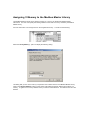
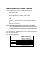
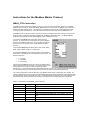
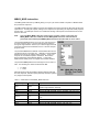
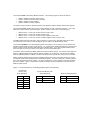
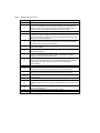
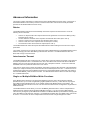
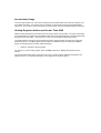
Using the Modbus Master Protocol Library (v1.2)
STEP 7–Micro/WIN Instruction Libraries makes communicating to Modbus slave devices easier by including
pre-configured subroutines and interrupt routines that are specifically designed for Modbus communications.
With the Modbus Master Protocol instructions, you can configure the S7-200 to act as a Modbus RTU
master device and communicate to one or more Modbus slave devices.
The Modbus Master Protocol instructions can be installed into the Libraries folder of the STEP 7–Micro/WIN
instruction tree. These new instructions allow you to make the S7-200 act as a Modbus master. When you
select a Modbus Master instruction, one or more associated subroutines are automatically added to your
project to support the Modbus Master Protocol.
There are two versions of the Modbus Master Protocol Library. One version utilizes port 0 of the CPU and
the other utilizes port 1 of the CPU. This document describes both libraries. The port 1 library has an “_P1”
appended to the POU names (i.e. MBUS_CTRL_P1) to denote that the POU utilizes port 1 on the CPU.
The libraries are identical in all other respects.
Requirements for Using the Modbus Master Protocol
The Modbus Master Protocol instructions use the following resources from the S7-200:
•
Initializing the Modbus Master Protocol dedicates the specific CPU port for Modbus Master Protocol
communications. When the CPU port is being used for Modbus Master Protocol communications,
it cannot be used for any other purpose, including communications with STEP 7-Micro/WIN. The
MBUS_CTRL instruction controls assignment of Port 0 to Modbus Master Protocol or PPI. The
MBUS_CTRL_P1 instruction (from the port 1 library) controls assignment of Port 1 to Modbus
Master Protocol or PPI.
•
The Modbus Master Protocol instructions affect all of the SM locations associated with Freeport
communications on the affected CPU communication port.
•
The Modbus Master Protocol instructions use 3 subroutines and 1 interrupt routine.
•
The Modbus Master Protocol instructions require about 1620 bytes of program space for the two
Modbus Master instructions and the support routines.
•
The variables for the Modbus Master Protocol instructions require a 284 byte block of V memory.
The starting address for this block is assigned by the user and is reserved for Modbus variables.
•
The S7-200 CPU must be firmware revision 2.00 or greater to support the Modbus Master Protocol
Library (CPU MLFB 21x-2xx23-0XB0).
•
The Modbus master library utilizes the user interrupts for some functions. The user interrupts must
not be disabled by the user program.
Note:
To change the operation of CPU communication port back to PPI so that you can
communicate with STEP 7-Micro/WIN, set the Mode parameter of the MBUS_CTRL
instruction to a zero (0).
You can also set the mode switch on the S7-200 to the STOP mode position. Either of these
methods will set the CPU communication port to communicate with STEP 7-Micro/WIN.
Execution Time for the Modbus Master Protocol
The Modbus Master Protocol requires a small amount of time every scan to execute the MBUS_CTRL
instruction. The time will be about 1.11 milliseconds when the MBUS_CTRL is initializing the Modbus
Master (first scan), and about 0.41 milliseconds on subsequent scans.
The scan time is extended when the MBUS_MSG subroutine executes a request. Most of the time is spent
calculating the Modbus CRC for the request and the response. The CRC (Cyclic Redundancy Check)
insures the integrity of the communications message. The scan time is extended by about 1.85
milliseconds for each word in the request and in the response. A maximum request/response (read or write
of 120 words) extends the scan time by approximately 222 milliseconds. A read request extends the scan
mainly when the response is received from the slave, and to a lesser extent when request is sent. A write
request extends the scan mainly when the data sent to the slave, and to a lesser extent when the response
is received.
Modbus Addressing
Modbus addresses are normally written as 5 character values containing the data type and the offset. The
first character determines the data type, and the last four characters select the proper value within the data
type. The Modbus Master instructions then map the addresses to the correct functions to send to the slave
device. The following Modbus addresses are supported by the Modbus Master instructions:
•
•
•
•
00001 to 09999 are discrete outputs (coils)
10001 to 19999 are discrete inputs (contacts)
30001 to 39999 are input registers (generally analog inputs)
40001 to 49999 are holding registers
All Modbus addresses are one-based, meaning that the first data value starts at address one. The range of
valid addresses will depend on the slave device. Different slave devices will support different data types and
address ranges.
Installing the Modbus Master Protocol Library
Before you can use the Modbus Master Protocol Library, you must add the library to STEP 7-Micro/WIN.
1.
Copy the Modbus Master Protocol Library (modbus master.mwl) to your computer. The library can
be placed anywhere on the computer, but the default location for STEP 7-Micro/WIN libraries is the
directory:
C:\Program Files\SIEMENS\Step 7-MicroWin V4.0\Lib\
2.
Select the File > Add/Remove Libraries… menu option. This will open the Add/Remove Libraries
Dialog.
3.
Click on the Add button and go to the directory where you placed the Modbus Master Protocol
Library file (modbus master.mwl or modbus_master_port1.mwl).
4.
Click the Save button to install the library. There will now be a new folder under the Libraries entry
in the Instruction Tree.
5.
Open the Modbus Master (v1.x) folder and you will see the Modbus Master instructions included in
the library.
Assigning V Memory to the Modbus Master Library
The Modbus Master Protocol Library requires a block of V memory to operate the Modbus Master
instructions. The user must specify the starting address for the block of memory needed by the Modbus
Master Library.
Go to the Instruction Tree and right-click on the Program Block entry. You will see the following:
Select the Library Memory… option to display the following dialog:
This dialog tells you how much memory is required for the included version of the Modbus Master Library.
Click on the Suggest Address button to have STEP 7-Micro/WIN suggest an address for the block of V
memory, or type in the V memory address where you want to locate the block. The address must be a VB
address.
Using the Modbus Master Protocol Instructions
To use the Modbus Master Protocol instructions in your S7-200 program, follow these steps:
1.
Install the Modbus Master Protocol Library. This was described in a prior section (Installing the
Modbus Master Protocol Library).
2.
Insert the MBUS_CTRL instruction in your program and execute the MBUS_CTRL on every scan.
You can use the MBUS_CTRL instruction either to initiate or to change the Modbus
communications parameters. When you insert the MBUS_CTRL instruction, several protected
subroutines and interrupt routines are automatically added to your program.
3.
Assign a starting address for the 284 bytes of consecutive V memory required for Modbus Master
Protocol instructions as described in the previous section (Assigning V Memory to the Modbus
Library).
4.
Place one or more MBUS_MSG instructions in your program. You can add as many MBUS_MSG
instructions to your program as you require, but only one of these instructions can be active at a
time.
5.
Connect a communications cable between Port 0 on the S7-200 CPU (or Port 1 for the Port 1
library) and the Modbus slave devices.
Caution: Interconnecting equipment with different reference potentials can cause unwanted
currents to flow through the interconnecting cable. These unwanted currents can cause
communications errors or damage equipment.
Ensure that all equipment that is connected with a communications cable either shares a
common circuit reference or is isolated to prevent unwanted current flows.
The Modbus Master protocol instructions utilize the Modbus functions shown in the table below to read or
write a specific Modbus address. The Modbus slave device must support the Modbus function(s) required to
read or write a particular Modbus address.
Table 1 – Required Slave Function Support
Modbus
Address
Read or
Write
Modbus Slave Function Required
Read
Function 1
Write
Function 5 for a single output point
Function 15 for multiple output points
10001 – 19999
discrete inputs
Read
Function 2
Write
not possible
30001 – 39999
input registers
Read
Function 4
Write
not possible
Read
Function 3
Write
Function 6 for a single register
Function 16 for multiple registers
00001 – 09999
discrete outputs
40001 – 49999
holding registers
Instructions for the Modbus Master Protocol
MBUS_CTRL Instruction
The MBUS_CTRL instruction (or MBUS_CTRL_P1 for port 1) is used to initialize, monitor or to disable
Modbus communications. Before the MBUS_MSG instruction can be used, the MBUS_CTRL instruction
must be executed without errors. The instruction completes and the Done bit is set immediately before
continuing to the next instruction. This instruction is executed on each scan when the EN input is on.
The MBUS_CTRL instruction must be called every scan (including the first scan) to allow it to monitor the
progress of any outstanding messages initiated with the MBUS_MSG instruction. The Modbus Master
Protocol will not operate correctly unless MBUS_CTRL is called every scan.
The value for the Mode input selects the communications
protocol. An input value of 1 assigns the CPU port to Modbus
protocol and enables the protocol. An input value of 0 assigns
the CPU port to PPI system protocol and disables Modbus
protocol.
The parameter Baud sets the baud rate to 1200, 2400, 4800,
9600, 19200, 38400, 57600, or 115200 baud.
The parameter Parity is set to match the parity of the Modbus
slave device. All settings use one start bit and one stop bit. The
allowed values are:
•
•
•
0 - no parity
1 - odd parity
2 - even parity
The parameter Timeout is set to the number of milliseconds to
wait for the response from the slave. The Timeout value can be
set anywhere in the range of 1 millisecond through 32767
milliseconds. A typical value would be 1000 milliseconds (1 second). The Timeout parameter should be set
to a value large enough so that the slave device has time to respond at the selected baud rate.
The Timeout parameter is used to determine if the Modbus slave device is responding to a request. The
Timeout value determines how long the Modbus Master will wait for the first character of the response after
the last character of the request has been sent. The Modbus Master will receive the entire response from
the Modbus slave device if at least one character of the response is received within the Timeout time.
Table 3 – Parameters for the MBUS_CTRL instruction
Inputs/Outputs
Data Type
Operands
Mode
BOOL
I, Q,M, S, SM, T, C, V, L
Baud
DWORD
VD, ID, QD, MD, SD, SMD, LD, AC, Constant, *VD, *AC, *LD
Parity
BYTE
VB, IB, QB, MB, SB, SMB, LB, AC, Constant, *VD, *AC, *LD
Baud
DWORD
VD, ID, QD, MD, SD, SMD, LD, AC, Constant, *VD, *AC, *LD
Timeout
INT
VW, IW, QW, MW, SW, SMW, LW, AC, Constant, *VD, *AC,
*LD
Done
BOOL
I, Q,M, S, SM, T, C, V, L
Error
BYTE
VB, IB, QB, MB, SB, SMB, LB, AC, *VD, *AC,*LD
When the MBUS_CTRL instruction completes, the Done output is turned on.
The Error output contains the result of executing the instruction. The following table defines the error
conditions that could result from executing the MBUS_CTRL instruction.
Table 2 – MBUS_CTRL Error Codes
Error Code
Description
0
No error
1
Parity selection is not valid
2
Baud rate selection is not valid
3
Timeout selection is not valid
4
Mode selection is not valid
MBUS_MSG Instruction
The MBUS_MSG instruction (or MBUS_MSG_P1 for port 1)is used to initiate a request to a Modbus slave
and process the response.
The MBUS_MSG instruction initiates a request to a Modbus slave when the both the EN input and the First
inputs are on. Sending the request, waiting for the response and processing the response usually requires
several scans. The EN input must be on to enable the sending of the request, and should remain on until
the Done bit is set.
Note:
Only one MBUS_MSG instruction can be active at a time. If there is more than one
MBUS_MSG instruction enabled, the first MBUS_MSG instruction executed will be
processed and all subsequent MBUS_MSG instructions will abort with an error code 6.
The parameter First should be on for only one scan when there
is a new request to send. The First input should be pulsed on
through an edge detection element (i.e. Positive Edge) which will
cause the request to be transmitted one time. See the example
program below.
The parameter Slave is the address of the Modbus slave device.
The allowed range is 0 through 247. Address 0 is the broadcast
address and can only be used for write requests. There is no
response to a broadcast request to address 0. Not all slave
devices will support the broadcast address. The S7-200
Modbus Slave Library does not support the broadcast address.
The parameter RW specifies if this message is to be a read or a
write. The following two values are allowed for RW.
•
•
0 – Read
1 – Write
Discrete outputs (coils) and holding registers support both read
and write requests. Discrete inputs (contacts) and input registers
only support read requests.
Table 4 – Parameters for the MBUS_MSG instruction
Inputs/Outputs
Data Type
Operands
First
BOOL
I, Q,M, S, SM, T, C, V, L (Power flow conditioned by a
positive edge detection element)
Slave
BYTE
VB, IB, QB, MB, SB, SMB, LB, AC, Constant, *VD, *AC, *LD
RW
BYTE
VB, IB, QB, MB, SB, SMB, LB, AC, Constant, *VD, *AC, *LD
Addr
DWORD
VD, ID, QD, MD, SD, SMD, LD, AC, Constant, *VD, *AC, *LD
Count
INT
VW, IW, QW, MW, SW, SMW, LW, AC, Constant, *VD, *AC,
*LD
DataPtr
DWORD
&VB
Done
BOOL
I, Q,M, S, SM, T, C, V, L
Error
BYTE
VB, IB, QB, MB, SB, SMB, LB, AC, *VD, *AC, *LD
The parameter Addr is the starting Modbus address. The following ranges of values are allowed:
•
•
•
•
00001 to 09999
10001 to 19999
30001 to 39999
40001 to 49999
for discrete outputs (coils)
for discrete inputs (contacts)
for input registers
for holding registers
The specific range of values for Addr are based on the addresses that the Modbus slave device supports.
The parameter Count specifies then number of data elements to read or write in this request. The Count
will be the number of bits for the bit data types, and the number of words for the word data types.
•
•
•
•
Address 0xxxx – Count is the number of bits to read or write
Address 1xxxx – Count is the number of bits to read
Address 3xxxx – Count is the number of input register words to read
Address 4xxxx – Count is the number of holding register words to read or write
The MBUS_MSG instruction will read or write a maximum of 120 words or 1920 bits (240 bytes of data).
The actual limit on the value of Count will depend upon the limits in the Modbus slave device.
The parameter DataPtr is an indirect address pointer which points to the V memory in the S7-200 CPU for
the data associated with the read or write request. For a read request, DataPtr should point to the first CPU
memory location used to store the data read from the Modbus slave. For a write request, DataPtr should
point to the first CPU memory location of the data to be sent to the Modbus slave.
The DataPtr value is passed into MBUS_MSG as an indirect address pointer. For example, if the data to be
written to a Modbus slave devices starts at address VW200 in the S7-200 CPU, the value for the DataPtr
would be &VB200 (address of VB200). Pointers must always be a type VB even if they point to word data.
Holding registers (address 4xxxx) and input registers (address 3xxxx) are word values (2 bytes or 16 bits).
S7-200 CPU words are formatted the same as Modbus registers. The lower numbered V-memory address
is the most significant byte of the register. The higher numbered V-memory address is the least significant
byte of the register. Figure 1 below shows how the S7-200 byte and word addressing corresponds to the
Modbus register format.
Figure 1 – S7-200 CPU Memory and Holding Registers (data in hexadecimal)
S7-200 CPU
Memory with
Byte Addressing
S7-200 CPU Memory with
Word Addressing
Modbus Holding Registers
VB200
12
VW200
12 34
40001
12 34
VB201
34
VW202
56 78
40002
56 78
VB202
56
VW204
9A BC
40003
9A BC
VB203
78
VB204
9A
VB205
BC
The bit data (addresses 0xxxx and 1xxxx) areas are read and written as packed bytes, that is, 8 bits are
packed into each byte of data. The least significant bit of the first data byte is the addressed bit number (the
parameter Addr). If only a single bit is written then the bit must be in the least significant bit of the byte
pointed to by DataPtr.
Figure 2 – Format for Packed Bytes (Discrete input addresses shown)
Vx.7
Vx.0
10008
10007
10006
10005
10001
10002
10003
10004
For bit data addresses that do not start on even byte boundaries, the bit corresponding to the starting
address must be must be in the least significant bit of the byte. See Figure 3 for an example of the packed
byte format for 3 bits starting at Modbus address 10004.
Figure 3 – Format for Packed Bytes (Discrete input starting at address 10004)
Vx.7
0
Vx.0
0
0
0
0
1
1
1
10004
10005
10006
When writing to the discrete output data type (coils), the user is responsible for placing the bits in the correct
bit positions within the packed byte before the data is passed to the MBUS_MSG instruction via DataPtr.
The Done output is off while a request is being sent and the response is being received. The Done output is
on when the response is complete or when the MBUS_MSG instruction was aborted because of an error.
The Error output is valid only when the Done output is on. Table 5 on the next page is a list of error codes
returned by the MBUS_MSG instruction.
The low numbered error codes (1 through 8) are errors that are detected by the MBUS_MSG instruction.
These error codes generally indicate a problem with the input parameters of the MBUS_MSG instruction, or
a problem receiving the response from the slave. Parity and CRC errors indicate that there was a response
but that the data was not received correctly. This is usually caused by an electrical problem such as a bad
connection or electrical noise.
The high numbered error codes (starting with 101) are errors that are returned by the Modbus slave device.
These errors indicate that the slave does not support the requested function or that the requested address
(either data type or range of addresses) is not supported by the Modbus slave device.
Table 5 – MBUS_MSG Error Codes
Error Code
Description
0
No error
1
Parity error in response. This is only possible if even or odd parity is
used. The transmission was disturbed and possibly incorrect data was
received. This error is usually caused by an electrical problem such as
incorrect wiring or electrical noise affecting the communication.
2
Not used
3
Receive timeout. There was no response from the slave within the
Timeout time. Some possible causes are: bad electrical connection to the
slave device, master and slave are set to different baud rates and/or parity
settings, incorrect slave address.
4
Error in request parameter. One or more of the input parameters (Slave,
RW, Addr, or Count ) is set to an illegal value. Check the documentation
for allowed values for the input parameters.
5
Modbus master not enabled. Call MBUS_CTRL on every scan prior to
calling MBUS_MSG.
6
Modbus is busy with another request. Only one MBUS_MSG instruction
can be active at a time.
7
Error in response. The response received does not correspond to the
request. This indicates some problem in the slave device or that the
wrong slave device answered the request.
8
CRC error in response. The transmission was disturbed and possibly
incorrect data was received. This error is usually caused by an electrical
problem such as incorrect wiring or electrical noise affecting the
communication.
101
Slave does not support the requested function. See Table 1 for the
required slave function support needed for the requested address.
102
Slave does not support the data address. The requested address range of
Addr plus Count is outside the allowed address range of the slave.
103
Slave does not support the data type. The Addr type is not supported by
the slave device.
104
Slave device failure.
105
Slave accepted the message but the response is delayed. This is an error
for MBUS_MSG and the user program should resend the request at a later
time.
106
Slave is busy and rejected the message. You can try the same request
again to get a response.
107
Slave rejected the message for an unknown reason.
108
Slave memory parity error. There is an error in the slave device.
Example Program
This example program shows how to use the Modbus Master instructions to write and then read 4 holding
registers to and from a Modbus slave each time input I0.0 is turned on.
The S7-200 CPU will write 4 words starting at VW100 to the Modbus stave. The data will be written to 4
holding registers in the slave starting at address 40001.
The S7-200 CPU will then read 4 holding registers from the Modbus stave. The data will come from holding
registers 40010 – 40013 and be placed into the V-memory of the S7-200 CPU starting at VW200.
Figure 4 – Example Program Data Transfers
S7-200 CPU
Memory
Modbus Slave
Holding
Registers
….
VW100
40001
VW102
40002
VW104
40003
VW106
40004
….
….
….
….
VW200
40010
VW202
40011
VW204
40012
VW206
40013
….
….
The program will turn on outputs Q0.1 and Q0.2 if there is an error returned from the MBUS_MSG
instructions.
Initialize and monitor the Modbus Master by
calling MBUS_CTRL on every scan.
The Modbus Master is set for 9600 baud and
no parity. The slave is allowed 1000
milliseconds (1 second) to respond.
On the first scan reset the enable flags (M2.0
and M2.1) used for the two MBUS_MSG
instructions.
When I0.0 changes from OFF to ON, set the
enable flag for the first MBUS_MSG
instruction (M2.0).
Call the MBUS_MSG instruction when the
first enable flag (M2.0) is ON. The First
parameter must be set for only the first scan
that the instruction is enabled.
This instruction writes (RW = 1) 4 holding
registers to slave 2. The write data is taken
from VB100–VB107 (4 words) in the CPU and
written to address 40001 – 40004 in the
Modbus slave.
When the first MBUS_MSG instruction is
complete (Done goes from 0 to 1), clear the
enable for the first MBUS_MSG and set the
enable for the second MBUS_MSG
instruction.
If Error (MB1) is not zero then set Q0.1 to
show the error.
Call the second MBUS_MSG instruction when
the second enable flag (M2.1) is ON. The
First parameter must be set for only the first
scan that the instruction is enabled.
This instruction reads (RW = 0) 4 holding
registers from slave 2. The data is read from
address 40010 – 40013 in the Modbus slave
and copied to VB200 – VB207 (4 words) in
the CPU.
When the second MBUS_MSG instruction is
complete (Done goes from 0 to 1), clear the
enable for the second MBUS_MSG
instruction.
If Error (MB1) is not zero then set Q0.2 to
show the error.
Advanced Information
This section contains information for advanced uses of the Modbus Master Protocol Library. Most users of
the Modbus Master Protocol Library should not need this information and should not modify the default
operation of the Modbus Master Protocol Library.
Retries
The Modbus Master instructions will automatically resend the request to the slave device if one of the
following errors is detected:
•
•
•
•
•
There is no response within the response timeout time (parameter Timeout on the MBUS_CTRL)
instruction (Error code 3).
The time between characters of the response exceeded the allow value (Error code 3).
There is a parity error in the response from the slave (Error code 1).
There is a CRC error in the response from the slave (Error code 8).
The returned function did not match the request (Error code 7).
The Modbus Master will resend the request two additional times before setting the Done and Error output
parameters.
The number of retries can be changed by finding the symbol mModbusRetries in the Modbus Master symbol
table and changing this value after MBUS_CTRL has been executed. The mModbusRetries value is a
BYTE with a range of 0 to 255 retries.
Intercharacter Timeout
The Modbus Master will abort a response from a slave device if the time between characters in the response
exceeds a specified time limit. The default time is set to 100 milliseconds which should allow the Modbus
Master Protocol to work with most slave devices over wire or telephone modems. If this error is detected,
the MBUS CTRL Error parameter will be set to error code 3.
There may be cases where a longer time between characters is required, either because of the transmission
medium (i.e. telephone modem) or because the slave device itself requires more time. This timeout can be
lengthened by finding the symbol mModbusCharTimeout in the Modbus Master symbol table and changing
this value after MBUS_CTRL has been executed. The mModbusCharTimeout value is an INT with a range
of 1 to 30000 milliseconds.
Single vs. Multiple Bit/Word Write Functions
Some Modbus slave devices do not support the Modbus functions to write a single discrete output bit
(Modbus function 5) or to write a single holding register (Modbus function 6). These devices only support
the multiple bit write (Modbus function 15) or multiple register write (Modbus function 16) instead. The
MBUS_MSG instruction will return an error code 101 if the slave device does not support the single bit/word
Modbus functions.
The Modbus Master Protocol allows you to force the MBUS_MSG instruction to use the multiple bit/word
Modbus functions instead of the single bit/word Modbus functions. You can force the multiple bit/word
instructions by finding the symbol mModbusForceMulti in the Modbus Master symbol table and changing this
value after MBUS_CTRL has been executed. The mModbusForceMulti value is an BOOL value and should
be set to a ‘1’ to force the use of the multiple bit/word functions when a single bit/register is written.
Accumulator Usage
The accumulators (AC0, AC1, AC2, AC3) are utilized by the Modbus Master instructions and appear in the
Cross Reference listing. The values in the accumulators are saved and restored by the Modbus Master
instructions. All user data in the accumulators is preserved while executing the Modbus Master instructions.
Holding Registers Addresses Greater Than 9999
Modbus holding addresses are generally within the range of 40001 through 49999. This range is adequate
for most applications but there are some Modbus slave devices with data mapped into holding registers with
addresses greater than 9999. These devices do not fit the normal Modbus addressing scheme.
The Modbus Master instructions support addressing holding registers greater than 9999 via an alternate
addressing method. The MBUS_MSG instruction allows an additional range for the parameter Addr to
support an extended range of holding register addresses.
•
400001 to 465536 for holding registers
For example: to access holding register 16768, the Addr parameter of MBUS_MSG should be set to
416768.
The extended addressing allows access to the full range of 65536 possible addresses supported by the
Modbus protocol. This extended addressing is only supported for holding registers.