1
PROJECT PLANNING AND INSTALLATION MANUAL
HEAT PUMPS FOR HEATING AND HOT WATER PREPARATION
Interactive planning support:
www.dimplex.de/en/professional/online-planner
Always up-to-date
The current version of the following planning manuals
is available as a PDF file at
www.dimplex.de/en/downloads/planning-manuals
• Heat pumps for heating and hot water preparation
• Heating and cooling with heat pumps
• Heat pumps with simplified controller
Certified quality
Version 10/2007
Table of Contents
Table of Contents
Table of Contents.....................................................................................................................................................1
What are the Benefits of a Heat Pump? .................................................................................................................6
Glossary....................................................................................................................................................................6
Bibliography .............................................................................................................................................................8
Symbols ....................................................................................................................................................................8
Energy Content of Various Types of Fuel..............................................................................................................9
Conversion Tables ...................................................................................................................................................9
1 Selection and Design of Heat Pumps .............................................................................................................10
1.1 Design of Existing Heating Systems - Heat Pumps for the Renovation Market.............................................................................. 10
1.1.1 Heat consumption of the building to be heated ..................................................................................................................... 10
1.1.2 Determining the required flow temperature ........................................................................................................................... 10
1.1.3 Which renovation measures must be carried out for energy-saving heat pump operation? ................................................. 11
1.1.4 Choice of heat source (renovation) ....................................................................................................................................... 11
1.2 Heat Pumps for New Systems ........................................................................................................................................................ 12
1.2.1 Calculating the heat consumption of the building .................................................................................................................. 12
1.2.2 Determining the flow temperatures........................................................................................................................................ 12
1.2.3 Selecting the heat source ...................................................................................................................................................... 12
1.3 Additional Power Requirements...................................................................................................................................................... 12
1.3.1 Shut-off times of the utility company...................................................................................................................................... 12
1.3.2 Domestic hot water preparation............................................................................................................................................. 13
1.3.3 Hot water heating for a swimming pool ................................................................................................................................. 13
1.3.4 Determining the heat pump output ........................................................................................................................................ 13
2
Air-to-Water Heat Pumps ................................................................................................................................17
2.1 The Air as Heat Source................................................................................................................................................................... 17
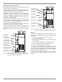
2.2 Air-to-Water Heat Pumps for Indoor Installation ............................................................................................................................. 17
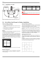
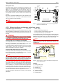
2.2.1 Requirements placed on the installation location .................................................................................................................. 17
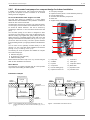
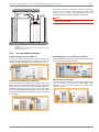
2.2.2 Air intake and air outlet via light wells.................................................................................................................................... 18
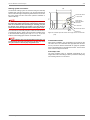
2.2.3 Heat pump rain guard............................................................................................................................................................ 18
2.2.4 Insulation of wall openings .................................................................................................................................................... 18
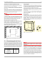
2.2.5 Air-to-water heat pumps in a compact design for indoor installation ..................................................................................... 19
2.2.6 Air duct hose set for air-to-water heat pumps (indoor installation) ........................................................................................ 20
2.2.7 GRC air ducts for air-to-water heat pumps (indoor installation) ............................................................................................ 20
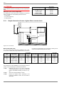
2.3 Dimensioning the Air Circuit............................................................................................................................................................ 21
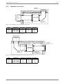
2.3.1 Height dimensions for use of glass fibre concrete ducts ....................................................................................................... 22
2.3.2 Installation in a corner ........................................................................................................................................................... 23
2.3.3 Installation on a wall .............................................................................................................................................................. 24
2.4 Air-to-Water Heat Pumps for Outdoor Installation........................................................................................................................... 24
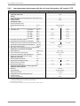
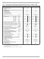
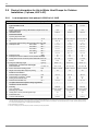
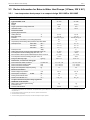
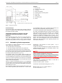
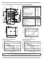
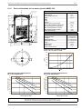
2.5 Device Information for Air-to-Water Heat Pumps for Indoor Installation (1-phase, 230 V AC) ....................................................... 26
2.5.1 Low-temperature heat pumps with the air circuit diverted at a 90° angle LIK 8ME ............................................................... 26
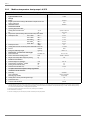
2.5.2 Low-temperature heat pumps with horizontal air circuit LI 11ME.......................................................................................... 27
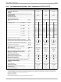
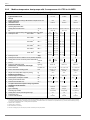
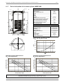
2.6 Device Information for Air-to-Water Heat Pumps for Indoor Installation (3-phase, 400 V AC) ...................................................... 28
2.6.1 Low-temperature heat pumps with the air circuit diverted at a 90° angle LIK 8TE................................................................ 28
2.6.2 Low-temperature heat pumps with the air circuit diverted at a 90° angle LI 9TE .................................................................. 29
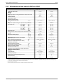
2.6.3 Low-temperature Heat Pumps with Horizontal Air Circuit LI 11TE to LI 16TE ...................................................................... 30
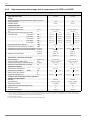
2.6.4 Low-temperature heat pumps with 2 compressors LI 20TE to LI 28TE ................................................................................ 31
2.6.5 High-temperature heat pumps with 2 compressors LIH 22TE to LIH 26TE .......................................................................... 32
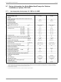
2.7 Device Information for Air-to-Water Heat Pumps for Outdoor Installation (1-phase, 230 V AC)..................................................... 33
2.7.1 Low-temperature heat pumps LA 11MS to LA 16MS ............................................................................................................ 33
2.8 Device Information for Air-to-Water Heat Pumps for Outdoor Installation (3-phase, 400 V AC).................................................... 34
2.8.1 Low-temperature heat pumps LA 8AS to LA 16AS ............................................................................................................... 34
2.8.2 Low-temperature heat pumps with 2 compressors LA 20AS to LA 28AS ............................................................................. 35
2.8.3 Medium-temperature heat pumps LA 9PS ............................................................................................................................ 36
2.8.4 Medium-temperature heat pumps LA 11PS .......................................................................................................................... 37
www.dimplex.de
1
2.8.5
2.8.6
Medium-temperature heat pumps with 2 compressors LA 17PS to LA 26PS....................................................................... 38
High-temperature heat pumps LA 22HS to LA 26HS............................................................................................................ 39
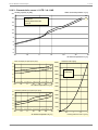
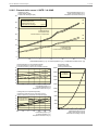
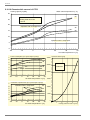
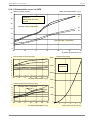
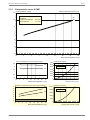
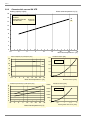
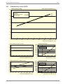
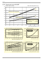
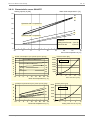
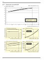
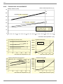
2.9 Characteristic Curves for Air-to-Water Heat Pumps (1-phase, 230 V AC) ..................................................................................... 40
2.9.1 Characteristic curves LIK 8ME.............................................................................................................................................. 40
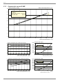
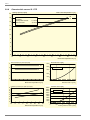
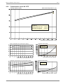
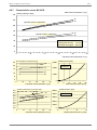
2.9.2 Characteristic curves LI 11ME / LA 11MS ............................................................................................................................ 41
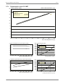
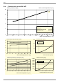
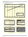
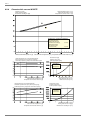
2.9.3 Characteristic curves LA 16MS............................................................................................................................................. 42
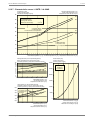
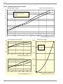
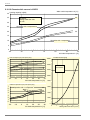
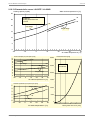
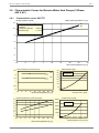
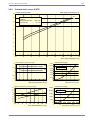
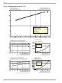
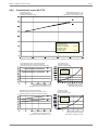
2.10 Characteristic Curves for Air-to-Water Heat Pumps (3-phase, 400 V AC) ..................................................................................... 43
2.10.1 Characteristic curves LIK 8TE / LI 9TE ................................................................................................................................. 43
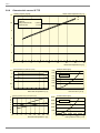
2.10.2 Characteristic curves LA 8AS ............................................................................................................................................... 44
2.10.3 Characteristic curves LI 11TE / LA 11AS.............................................................................................................................. 45
2.10.4 Characteristic curves LI 16TE / LA 16AS.............................................................................................................................. 46
2.10.5 Characteristic curves LI 20TE / LA 20AS.............................................................................................................................. 47
2.10.6 Characteristic curves LI 24TE / LA 24AS.............................................................................................................................. 48
2.10.7 Characteristic curves LI 28TE / LA 28AS.............................................................................................................................. 49
2.10.8 Characteristic curves LA 9PS ............................................................................................................................................... 50
2.10.9 Characteristic curves LA 11PS ............................................................................................................................................. 51
2.10.10 Characteristic curves LA 17PS ............................................................................................................................................. 52
2.10.11 Characteristic curves LA 22PS ............................................................................................................................................. 53
2.10.12 Characteristic curves LA 26PS ............................................................................................................................................. 54
2.10.13 Characteristic curves LIH 22TE / LA 22HS ........................................................................................................................... 55
2.10.14 Characteristic curves LIH 26TE / LA 26HS ........................................................................................................................... 56
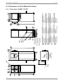
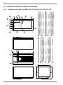
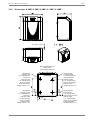
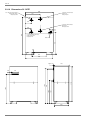
2.11 Dimensions of Air-to-Water Heat Pumps........................................................................................................................................ 57
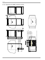
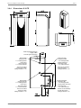
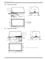
2.11.1 Dimensions LIK 8ME / LIK 8TE............................................................................................................................................. 57
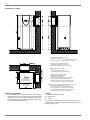
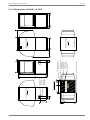
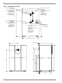
2.11.2 Dimensions LI 9TE................................................................................................................................................................ 59
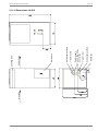
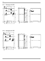
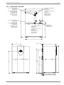
2.11.3 Dimensions LI 11ME / LI 11TE ............................................................................................................................................. 60
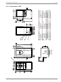
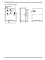
2.11.4 Dimensions LI 16TE.............................................................................................................................................................. 61
2.11.5 Dimensions LI 20TE.............................................................................................................................................................. 62
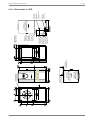
2.11.6 Dimensions LI 24TE / LI 28TE / LIH 22TE / LIH 26TE.......................................................................................................... 63
2.11.7 Dimensions LA 8AS .............................................................................................................................................................. 64
2.11.8 Dimensions LA 11MS / LA 11AS .......................................................................................................................................... 65
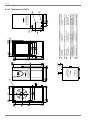
2.11.9 Dimensions LA 16MS / LA 16AS / LA 11PS ......................................................................................................................... 66
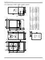
2.11.10 Dimensions LA 20AS / LA 17PS ........................................................................................................................................... 67
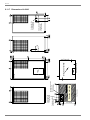
2.11.11 Dimensions LA 24AS / LA 28AS / LA 22PS / LA 26PS......................................................................................................... 68
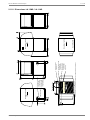
2.11.12 Dimensions LA 9PS .............................................................................................................................................................. 69
2.11.13 Dimensions LA 22HS / LA 26HS........................................................................................................................................... 70
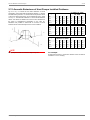
2.12 Acoustic Emissions of Heat Pumps Installed Outdoors.................................................................................................................. 71
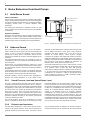
3 Brine-to-Water Heat Pump .............................................................................................................................. 72
3.1 Ground as Heat Source .................................................................................................................................................................. 72
3.1.1 Dimensioning information - the ground as heat source......................................................................................................... 72
3.1.2 Drying-out of buildings .......................................................................................................................................................... 72
3.1.3 Brine fluid .............................................................................................................................................................................. 72
3.2 Ground Heat Collector .................................................................................................................................................................... 74
3.2.1 Installation depth ................................................................................................................................................................... 74
3.2.2 Installation clearance ............................................................................................................................................................ 74
3.2.3 Collector surface and pipe length.......................................................................................................................................... 74
3.2.4 Installation ............................................................................................................................................................................. 75
3.2.5 Installation of the brine circuit................................................................................................................................................ 75
3.2.6 Standard dimensions of ground heat collectors. ................................................................................................................... 76
3.3 Borehole Heat Exchangers............................................................................................................................................................. 78
3.3.1 Dimensioning of borehole heat exchangers.......................................................................................................................... 78
3.3.2 Preparation of boreholes....................................................................................................................................................... 79
3.3.3 Additional heat source systems for ground heat usage ........................................................................................................ 79
3.4 Heat Source Absorber Systems (Indirect Use of Air or Solar Energy) ........................................................................................... 80
3.5 Device Information for Brine-to-Water Heat Pumps (1-Phase, 230 V AC) ..................................................................................... 81
3.5.1 Low-temperature heat pumps in a compact design SIK 11ME to SIK 16ME........................................................................ 81
3.5.2 Low-temperature heat pumps SI 5ME to SI 14ME................................................................................................................ 82
3.6 Device Information for Brine-to-Water Heat Pumps (3-Phase, 400V AC) ...................................................................................... 83
3.6.1 Low-temperature heat pumps in a compact design SIK 7TE to SIK 14TE ........................................................................... 83
3.6.2 Low-temperature heat pumps SI 5TE to SI 11TE ................................................................................................................. 84
3.6.3 Low-temperature heat pumps SI 14TE to SI 21TE ............................................................................................................... 85
3.6.4 Low-temperature heat pumps SI 24TE to SI 37TE ............................................................................................................... 86
3.6.5 Low-temperature heat pumps SI 50TE to SI 130TE ............................................................................................................. 87
3.6.6 High-temperature heat pumps SIH 20TE.............................................................................................................................. 88
3.6.7 High-temperature heat pumps SIH 40TE.............................................................................................................................. 89
2
Table of Contents
3.7 Characteristic Curves for Brine-to-Water Heat Pumps (1-Phase, 230 V AC) ................................................................................. 90
3.7.1 Characteristic curves SIK 11ME............................................................................................................................................ 90
3.7.2 Characteristic curves SIK 16ME............................................................................................................................................ 91
3.7.3 Characteristic curves SI 5ME ................................................................................................................................................ 92
3.7.4 Characteristic curves SI 7ME ................................................................................................................................................ 93
3.7.5 Characteristic curves SI 9ME ................................................................................................................................................ 94
3.7.6 Characteristic curves SI 11ME .............................................................................................................................................. 95
3.7.7 Characteristic curves SI 14ME .............................................................................................................................................. 96
3.8 Characteristic Curves for Brine-to-Water Heat Pumps (3-Phase, 400 V AC) ................................................................................. 97
3.8.1 Characteristic curves SIK 7TE............................................................................................................................................... 97
3.8.2 Characteristic curves SIK 9TE............................................................................................................................................... 98
3.8.3 Characteristic curves SIK 11TE............................................................................................................................................. 99
3.8.4 Characteristic curves SIK 14TE........................................................................................................................................... 100
3.8.5 Characteristic curves SI 5TE ............................................................................................................................................... 101
3.8.6 Characteristic curves SI 7TE ............................................................................................................................................... 102
3.8.7 Characteristic curves SI 9TE ............................................................................................................................................... 103
3.8.8 Characteristic curves SI 11TE ............................................................................................................................................. 104
3.8.9 Characteristic curves SI 14TE ............................................................................................................................................. 105
3.8.10 Characteristic curves SI 17TE ............................................................................................................................................. 106
3.8.11 Characteristic curves SI 21TE ............................................................................................................................................. 107
3.8.12 Characteristic curves SI 24TE ............................................................................................................................................. 108
3.8.13 Characteristic curves SI 37TE ............................................................................................................................................. 109
3.8.14 Characteristic curves SI 50TE ............................................................................................................................................. 110
3.8.15 Characteristic curves SI 75TE ............................................................................................................................................. 111
3.8.16 Characteristic curves SI 100TE ........................................................................................................................................... 112
3.8.17 Characteristic curves SI 130TE ........................................................................................................................................... 113
3.8.18 Characteristic curves SIH 20TE .......................................................................................................................................... 114
3.8.19 Characteristic curves SIH 40TE .......................................................................................................................................... 115
3.9 Dimensions of Brine-to-Water Heat Pumps .................................................................................................................................. 116
3.9.1 Dimensions SIK 11ME, SIK 16ME, SIK 7TE, SIK 9TE, SIK 11TE, SIK 14TE..................................................................... 116
3.9.2 Dimensions SI 5ME, SI 7ME, SI 9ME, SI 11ME, SI 14ME.................................................................................................. 117
3.9.3 Dimensions SI 5TE, SI 7TE, SI 9TE, SI 11TE, SI 14TE, SI 17TE....................................................................................... 118
3.9.4 Dimensions SI 21TE............................................................................................................................................................ 119
3.9.5 Dimensions SI 24TE............................................................................................................................................................ 120
3.9.6 Dimensions SI 37TE............................................................................................................................................................ 121
3.9.7 Dimensions SI 50TE............................................................................................................................................................ 122
3.9.8 Dimensions SI 75TE............................................................................................................................................................ 122
3.9.9 Dimensions SI 100TE.......................................................................................................................................................... 123
3.9.10 Dimensions SI 130TE.......................................................................................................................................................... 124
3.9.11 Dimensions SIH 20TE ......................................................................................................................................................... 125
3.9.12 Dimensions SIH 40TE ......................................................................................................................................................... 126
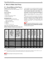
4 Water-to-Water Heat Pump ............................................................................................................................127
4.1 Ground Water as Heat Source...................................................................................................................................................... 127
4.2 Water Quality Requirements ......................................................................................................................................................... 128
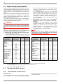
4.3 Tapping the Heat Source .............................................................................................................................................................. 128
4.3.1 Ground water as heat source .............................................................................................................................................. 128
4.3.2 Waste heat from cooling water as the heat source ............................................................................................................. 129
4.4 Device Information for Water-to-Water Heat Pumps (1-phase, 230 V AC)................................................................................... 130
4.5 Low-Temperature Heat Pumps WI 9ME to WI 14ME ................................................................................................................... 130
4.6 Device Information for Water-to-Water Heat Pumps (3-Phase, 400 V AC) .................................................................................. 131
4.6.1 Low-temperature heat pumps WI 9TE to WI 27TE.............................................................................................................. 131
4.6.2 Low-temperature heat pumps with 2 compressors WI 40CG to WI 90CG .......................................................................... 132
4.7 Characteristic Curves for Water-to-Water Heat Pumps (1-Phase, 230 V AC) .............................................................................. 133
4.7.1 Characteristic curves WI 9ME ............................................................................................................................................. 133
4.7.2 Characteristic curves WI 14ME ........................................................................................................................................... 134
4.8 Characteristic Curves for Water-to-Water Heat Pumps (3-Phase, 400 V AC) .............................................................................. 135
4.8.1 Characteristic curves WI 9TE .............................................................................................................................................. 135
4.8.2 Characteristic curves WI 14TE ............................................................................................................................................ 136
4.8.3 Characteristic curves WI 18TE ............................................................................................................................................ 137
4.8.4 Characteristic curves WI 22TE ............................................................................................................................................ 138
4.8.5 Characteristic curves WI 27TE ............................................................................................................................................ 139
4.8.6 Characteristic curves WI 40CG ........................................................................................................................................... 140
4.8.7 Characteristic curves WI 90CG ........................................................................................................................................... 141
4.9 Dimensions of Water-to-Water Heat Pumps ................................................................................................................................. 142
www.dimplex.de
3
4.9.1
4.9.2
4.9.3
Dimensions WI 9ME, WI 14ME, WI 9TE, WI 14TE, WI 18TE, WI 22TE and WI 27TE....................................................... 142
Dimensions WI 40CG.......................................................................................................................................................... 143
Dimensions WI 90CG.......................................................................................................................................................... 143
5 Noise Emissions from Heat Pumps.............................................................................................................. 144
5.1 Solid-Borne Sound........................................................................................................................................................................ 144
5.2 Airborne Sound............................................................................................................................................................................. 144
5.2.1 Sound Pressure Level and Sound Power Level.................................................................................................................. 144
5.2.2 Emission and Immission ..................................................................................................................................................... 144
5.2.3 Sound propagation.............................................................................................................................................................. 145
6 Domestic Hot Water Preparation and Ventilation with Heat Pumps ......................................................... 147
6.1 Domestic Hot Water Heating with the Heat Pumps for Heating Purposes ................................................................................... 147
6.1.1 Requirements placed on the domestic hot water cylinder................................................................................................... 147
6.1.2 Domestic hot water cylinder for heat pumps for heating purposes ..................................................................................... 147
6.1.3 Attainable cylinder temperatures......................................................................................................................................... 149
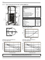
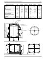
6.1.4 Device information for hot water cylinder design WWSP 229E .......................................................................................... 150
6.1.5 Device information for hot water cylinder WWSP 332 ........................................................................................................ 151
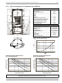
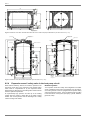
6.1.6 Device information for hot water cylinder design WWSP 442E .......................................................................................... 152
6.1.7 Device information for hot water cylinder WWSP 880 ........................................................................................................ 153
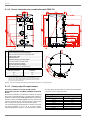
6.1.8 Device information for hot water cylinder WWSP 900 ........................................................................................................ 154
6.1.9 Device information for combination tank PWS 332............................................................................................................ 155
6.1.10 Device information for combination tank PWD 750............................................................................................................. 156
6.1.11 Country-specific requirements ............................................................................................................................................ 156
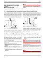
6.1.12 Connecting more than one domestic hot water cylinder in a single circuit.......................................................................... 157
6.2 Domestic Hot Water Heating with Domestic Hot Water Heat Pumps........................................................................................... 157
6.2.1 Air circulation variations ...................................................................................................................................................... 159
6.2.2 Device information for domestic hot water heat pumps ...................................................................................................... 160
6.3 Domestic Ventilation Units for DHW Preparation ......................................................................................................................... 160
6.4 Basic Principles for Planning Domestic Ventilation Systems........................................................................................................ 161
6.4.1 Calculation of the air volume............................................................................................................................................... 161
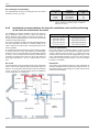
6.4.2 Installation recommendations for domestic ventilation units and the positioning of the fresh air and exhaust air valves ... 162
6.4.3 Calculating the overall pressure drop.................................................................................................................................. 163
6.5 Compact Domestic Ventilation Unit (Exhaust Air) LWP 300W ..................................................................................................... 163
6.6 Device Information for Compact Domestic Ventilation Units (Exhaust Air) .................................................................................. 165
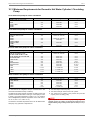
6.7 Comparison of the Convenience and the Costs of Different Types of Domestic Hot Water Heating Systems ............................ 166
6.7.1 Decentralized domestic hot water supply (e.g. continuous-flow heaters) ........................................................................... 166
6.7.2 Cylinder with electric immersion heater (off-peak electricity) .............................................................................................. 166
6.7.3 Domestic hot water heat pump ........................................................................................................................................... 166
6.7.4 Domestic ventilation unit with domestic hot water preparation ........................................................................................... 166
6.7.5 Summary............................................................................................................................................................................. 166
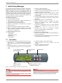
7 Heat Pump Manager....................................................................................................................................... 167
7.1 Operation ...................................................................................................................................................................................... 167
7.1.1 Attaching the wall-mounted heat pump manager (heating) ................................................................................................ 168
7.1.2 Temperature sensor (heating controller N1) ....................................................................................................................... 168
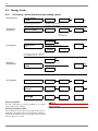
7.2 General Menu Structure ............................................................................................................................................................... 170
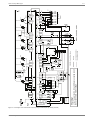
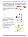
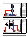
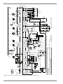
7.3 Circuit Diagram of the Wall-Mounted Heat Pump Manager.......................................................................................................... 172
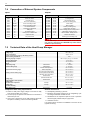
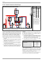
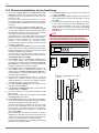
7.4 Connection of External System Components ............................................................................................................................... 174
7.5 Technical Data of the Heat Pump Manager.................................................................................................................................. 174
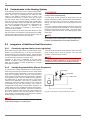
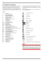
8 Integration of the Heat Pump in the Heating System ................................................................................. 175
8.1 Hydraulic Requirements ............................................................................................................................................................... 175
8.2 Guarantee Frost Protection .......................................................................................................................................................... 175
8.3 Safeguard the Heating Water Flow............................................................................................................................................... 175
8.3.1 Arithmetic calculation of the temperature spread................................................................................................................ 175
8.3.2 Temperature spread in relation to the heat source temperature......................................................................................... 176
8.3.3 Overflow valve..................................................................................................................................................................... 176
8.3.4 Differential pressureless manifold ....................................................................................................................................... 176
8.3.5 Dual differential pressureless manifold ............................................................................................................................... 177
8.4 Hot Water Distribution System...................................................................................................................................................... 177
8.4.1 KPV 25 compact manifold................................................................................................................................................... 177
8.4.2 KPV 25 compact manifold with EB KPV extension module ................................................................................................ 178
4
Table of Contents
8.4.3
DDV 32 dual differential pressureless manifold................................................................................................................... 178
8.5 Buffer Tank.................................................................................................................................................................................... 180
8.5.1 Heating systems with individual room control...................................................................................................................... 180
8.5.2 Heating systems without individual room control................................................................................................................. 180
8.5.3 Buffer tank for bridging shut-off times.................................................................................................................................. 180
8.5.4 Expansion vessel / safety valve in the heat pump circuit .................................................................................................... 182
8.5.5 Check valve ......................................................................................................................................................................... 183
8.6 Flow Temperature Limit of Underfloor Heating ............................................................................................................................. 183
8.6.1 Flow temperature limiting via a mixer limit switch................................................................................................................ 183
8.6.2 Flow temperature limiting using mixer bypass..................................................................................................................... 183
8.7 Mixer ............................................................................................................................................................................................. 183
8.7.1 Four-way mixer.................................................................................................................................................................... 183
8.7.2 Three-way mixer.................................................................................................................................................................. 183
8.7.3 Three-way solenoid valve (switching valve) ........................................................................................................................ 183
8.8 Contaminants in the Heating System............................................................................................................................................ 184
8.9 Integration of Additional Heat Generators..................................................................................................................................... 184
8.9.1 Constantly regulated boiler (mixer regulation)..................................................................................................................... 184
8.9.2 Variably-Regulated Boiler (Burner Regulation) ................................................................................................................... 184
8.9.3 Renewable heat sources ..................................................................................................................................................... 185
8.10 Heating a Swimming Pool ............................................................................................................................................................. 185
8.11 Constant-Regulated Tank Charging.............................................................................................................................................. 185
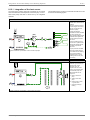
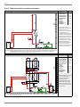
8.12 Hydraulic Integration ..................................................................................................................................................................... 186
8.12.1 Integration of the heat source.............................................................................................................................................. 187
8.12.2 Monovalent brine-to-water heat pump................................................................................................................................. 188
8.12.3 Heat pumps in compact design ........................................................................................................................................... 190
8.12.4 Mono energy heat pump heating system ............................................................................................................................ 191
8.12.5 Combination tanks and combo tanks .................................................................................................................................. 194
8.12.6 Bivalent heat pump heating system..................................................................................................................................... 195
8.12.7 Integration of renewable heat sources ................................................................................................................................ 197
8.12.8 Swimming pool water preparation ....................................................................................................................................... 199
8.12.9 Parallel Connection of Heat Pumps..................................................................................................................................... 200
9 Investment and Operating Costs...................................................................................................................201
9.1 Incidental Costs............................................................................................................................................................................. 201
9.2 Energy Costs................................................................................................................................................................................. 202
9.2.1 Oil heating - monovalent heat pump heating system .......................................................................................................... 202
9.2.2 Oil heating - mono energy heat pump heating systems ...................................................................................................... 203
9.2.3 Oil heating - parallel bivalent heat pump heating system .................................................................................................... 204
9.3 Calculation Sheet for Approximate Determination of the Annual Performance Factor of a Heat Pump System .......................... 205
10 Help with Planning and Installation ..............................................................................................................207
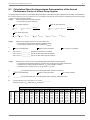
10.1 Template for Experimental Determination of the Actually Required System Temperature........................................................... 207
10.2 Electrical Installations for the Heat Pump ..................................................................................................................................... 208
10.3 Minimum Requirements for Domestic Hot Water Cylinder / Circulating Pump ............................................................................. 211
10.4 Order Form for (Heating/Cooling) Heat Pump Start-Up ................................................................................................................ 212
www.dimplex.de
5
What are the Benefits of a Heat Pump?
The fact that a large percentage of our energy supply is produced
from fossil fuels poses serious consequences for our
environment. Large quantities of pollutants such as sulphur and
nitrogen oxide are released during combustion.
Domestic space heating with fossil fuels contributes significantly
to pollutant emissions because extensive emission control
measures, such as those used in modern power plants, cannot
be carried out. Since our oil and gas reserves are limited, basing
such a large percentage of our energy supply on fossil fuel
sources also presents a serious problem.
The way electrical energy is generated will change in the future
to favour more renewable or newly developed generation
methods. You, too, can be a part of this development because
electricity as the energy of the future is the operating energy of
heat pumps.
What does a heat pump do?
A heat pump is a type of “transport device” that raises the
temperature level of the heat that is freely available in the
environment.
How does a heat pump convert low temperature
heat into higher temperature heat?
It extracts stored solar heat from the environment – ground,
water (e.g. ground water) and air (e.g. outside air) – and transfers
this, along with the operating energy, in the form of heat to the
heating and hot water system.
Heat cannot transfer from a cold body to a warm body on its own.
Rather, it flows from a body with a higher temperature to a body
with a lower temperature (Second Law of Thermodynamics). For
this reason, the heat pump must raise the temperature of the
thermal energy extracted from the environment using high-grade
energy - e.g. electricity for the drive motor - to a level suitable for
heating and domestic hot water preparation.
Heat pumps work like a refrigerator – in other words, the same
technology is applied but the function is reversed. It extracts heat
from a cold environment which can then be used for heating and
domestic hot water preparation.
Glossary
Defrosting
Utility company shut-off times
Regular routine for removing frost and ice from evaporators on
air-to-water heat pumps by applying heat. Air-to-water heat
pumps with reversal of the direction of circulation feature the
rapid and energy efficient defrosting properties required.
Local utility companies offer special tariffs for heat pumps
providing the power supply can be shut off by the utility company
at certain times of day. The power supply can, for example, be
interrupted for 3 X 2 hours within a 24-hour period. This means
that the daily heat output (quantity of heat produced daily) must
be produced within the period of time in which electrical energy is
available.
Bivalent-parallel operation
The bivalent operating mode (today this is normally bivalentparallel operation) functions with two heat generators (two
sources of energy), i.e. the heat pump covers the heating
requirements up to a determined temperature limit (as a rule
-5 °C) and is then backed up by a second energy source in
parallel.
Bivalent-renewable operating mode
The bivalent-renewable operating mode makes it possible to
incorporate renewable heat sources such as wood or thermal
solar energy. Should renewable energy sources be available,
then heat pump is blocked and the current heating, hot water or
swimming pool needs are met by the renewable cylinder.
Carnot factor
The ideal reference cycle for all thermodynamic cycles is the socalled Carnot cycle. This (theoretical) model cycle gives
maximum efficiency and - in comparison to a heat pump - the
theoretically greatest possible COP. The Carnot factor is based
solely on the temperature difference between the warm side and
the cold side.
D-A-CH seal of approval
Certificate for heat pumps in Germany, Austria and Switzerland
which fulfil specific technical requirements, have a 2-year
warranty, ensure the availability of spare parts for up to 10 years
and whose manufacturers offer a comprehensive customer
service network. The seal of approval also certifies that a line of
heat pumps has been manufactured as a series.
6
Expansion valve
Heat pump component between the liquefier and the evaporator
for reducing the condensation pressure to coincide with the
respective evaporation pressure determined by the evaporation
temperature. The expansion valve also controls the quantity of
refrigerant to be injected in relation to the respective evaporator
load.
Limit temperature / bivalence point
The outside temperature at which the 2nd heat generator is
additionally connected in mono energy (electric heating element)
and bivalent-parallel operation (e.g. boiler), and both modes of
operation jointly provide the house with heat.
Annual performance factor
The annual performance factor is defined as the ratio of the
quantity of electrical energy supplied in one year to the amount of
thermal energy extracted by the heat pump system. It is based
on a particular heating system taking the respective design of
that system into consideration (temperature level and
temperature difference) and is not the same as the coefficient of
performance.
Annual effort figure
The annual effort figure is exactly the opposite of the
performance factor. The annual effort figure indicates what input
(e.g. electrical energy) is required to achieve a defined benefit
(e.g. heating energy). The annual effort figure also includes the
energy for the auxiliary drives. The VDI Guideline VDI 4650 is
used to calculate the annual effort figure.
Glossary
Cooling capacity
Sound pressure level
Heat flow which is extracted from the surroundings by the
evaporator of a heat pump. The heat output of the compressor is
calculated from the electrical power consumption and
refrigerating capacity applied.
The sound pressure level measured in the surroundings is not a
machine-specific quantity, but a quantity dependent on the test
distance and the test location.
Refrigerant
The sound power level is a machine-specific and comparable
parameter for the acoustic output emitted by a heat pump. Both
the sound emission level to be expected at particular distances
and the acoustic environment can be estimated. The standard
treats the sound power level as a characteristic noise value.
The working medium used in a refrigerating machine or heat
pump is called a refrigerant. It can be characterized as a fluid
which is used for transferring heat in a refrigerating system.
Refrigerants absorb heat at a low temperature and pressure and
emit heat at a higher temperature and pressure. Refrigerants
which are non-poisonous and non-inflammable are designated
as safety refrigerants.
COP, coefficient of performance
The ratio between the absorbed electrical energy and the heat
output emitted by the heat pump is expressed by the coefficient
of performance (COP). This is measured under standardized
boundary conditions in a laboratory according to EN 255 (e.g. for
air A2/W35, A2= air intake temperature +2 °C, W35= heating
water flow temperature 35 °C). A COP of 3.2, for example,
means that 3.2 times the consumed electrical energy is available
as usable heat output.
Ig p,h diagram
Graphic representation of the thermodynamic properties of a
working medium (enthalpy, pressure, temperature).
Mono energy operation
In principle, the mono energy mode of operation is a bivalentparallel mode of operation utilizing only one source of energy,
normally electricity. The heat pump supplies a large part of the
required heat output. An electric heating element supplements
the heat pump on those few days during the year with extremely
low external temperatures.
Air-to-water heat pumps are normally dimensioned for a limit
temperature (also known as the bivalence point) of approx.
-5 °C.
Monovalent operation
In this operating mode, the annual heat consumption of the
building is completely covered (100%). This type of application
should be preferred wherever possible.
Brine-to-water and water-to-water heat pumps are normally
operated in monovalent mode.
Buffer tank
The installation of a heating water buffer tank is basically
recommended to lengthen the runtimes of the heat pump during
periods of reduced heating demand.
A buffer tank is absolutely essential for air-to-water heat pumps
to guarantee a minimum runtime of 10 minutes during defrosting
(regular routine for removing frost and ice from the evaporator).
Sound
A distinction is made between two types of sound, airborne
sound and solid-borne sound. Airborne sound is sound which
spreads through the air. Solid-borne sound spreads through solid
materials or fluids and is also partially emitted as airborne sound.
The audible sound range is between 16 and 16,000 Hz.
Sound power level
Brine / brine fluid
Frost-proof mixture consisting of water and a glycol-based antifreeze concentrate for use in ground heat collectors and
borehole heat exchangers.
Evaporator
Heat exchanger of a heat pump in which a heat flow is extracted
by evaporation of a working medium of the heat source (air,
ground water, ground) at a low temperature and with a low
pressure.
Compressor
Machine for the mechanical conveyance and compression of
gases. The pressure and temperature of the refrigerant are
raised considerably by means of compression.
Liquefier
Heat exchanger of a heat pump in which the heat flow is emitted
by liquifaction of a working medium.
Heat consumption calculation
Accurate dimensioning is essential for heat pump systems
because overdimensioned systems increase energy costs and
have a negative effect on efficiency.
The heat consumption is calculated on the basis of national
standards.
The specific heat consumption (W/m2) is multiplied by the living
space area to be heated. The result is the total heat consumption
including both the transmission heat consumption as well as the
ventilation heat consumption.
Heating system
The heating system (radiators and circulation pump) has a large
influence on the efficiency of the heat pump heating system, and
should function with the lowest possible flow temperatures. It
consists of the system used for conveying the heat transfer
medium from the warm side of the heat pump to the heat
consumers. For example, in a detached house the heating
system consists of the piping for heat distribution, the underfloor
heating system and/or the radiators and includes all auxiliary
equipment as well.
Heat pump system
A heat pump system consists of the heat pump and the heat
source system. Heat source systems for brine-to-water and
water-to-water heat pumps must be separately tapped.
Heat pump heating system
Complete system consisting of the heat source system, the heat
pump and the heating system.
Heat source
Medium from which heat is extracted with the heat pump.
www.dimplex.de
7
Heat source system
Panel heating
System for the extraction of heat from a heat source and the
conveyance of the heat transfer medium between the heat
source and the heat pump including all auxiliary equipment.
Panel heating has water flowing through it and functions like a
large radiator. It has the same advantages as underfloor heating.
As a rule, a temperature of 25 °C to 28 °C is sufficient for the
heat transfer which is mainly supplied to the rooms in the form of
radiant heat.
Heat transfer medium
Liquid or gaseous medium (e.g. water, brine or air) with which
heat is conveyed.
Bibliography
RWE Energie Bau-Handbuch (12. Ausgabe), VWEW VLG U.
Wirtschaftsgesellschaft, ISBN 3-87200-700-9, Frankfurt 1998
Breidert, Hans-Joachim; Schittenhelm, Dietmar: Formeln,
Tabellen und Diagramme für die Kälteanlagentechnik A.
MUELLER JUR.VLG.C.F., ISBN 3788076496, Heidelberg 1999
Dubbel Taschenbuch für den Maschinenbau (20. Auflage),
SPRINGER VERLAG GMBH & CO KG, ISBN 3540677771,
Berlin 2001
DIN Deutsches Institut für Normung e.V., Beuth Verlag GmbH,
Berlin.
VDI-Richtlinien – Gesellschaft technische Gebäudeausrüstung,
Beuth Verlag GmbH, Berlin.
Symbols
Symbol
Unit
Mass
Size
M
kg
Density
ρ
kg/m3
Time
t
s
h
Additional units (definition)
1 h = 3,600 s
3
Volume flow
9
m /s
Mass flow
0
kg/s
Force
F
N
1 N = 1 kg m/s2
Pressure
p
N/m2; Pa
1 Pa = 1 N/m2
1 bar = 105 Pa
E, Q
A
kWh
1 J = 1 Nm = 1 Ws = 1 kg m2/s2
1 kWh = 3600 kJ = 3.6 MJ
Energy, work, heat (quantity)
H
A
(Heat) output
Heat flow
Enthalpy
P, 4
W
kW
1 W = 1 J/s = 1 Nm/s
Temperature
T
K
°C
Absolute temperature, temperature difference
Temperature in °Celsius
LWA
LPA
dB(re 1pW)
dB(re 20μPa)
Sound pressure level, sound power level
Sound power
Sound pressure
Efficiency
COP, coefficient of performance
η
-
ε (COP)
-
Performance factor
ß
Specific heat content
c
Output figures
For example, annual performance factor
J/(kg K)
Greek alphabet
8
α
Α
alpha
ι
Ι
β
γ
δ
iota
ρ
Β
beta
κ
Γ
gamma
λ
Δ
delta
Ρ
rho
Κ
kappa
Χ
lambda
σ
Σ
sigma
τ
Τ
μ
Μ
tau
mu
υ
Υ
ypsilon
ε
Ε
epsilon
ν
Ν
nu
ϕ
Α
phi
ζ
Ζ
zeta
ξ
Ξ
xi
χ
Χ
chi
η
Η
eta
ο
Ε
omicron
ψ
Ψ
psi
Α
θ
theta
π
Π
pi
ω
Ω
omega
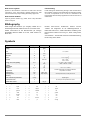
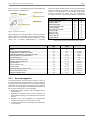
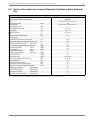
Energy Content of Various Types of Fuel
Energy Content of Various Types of Fuel
max. CO2 emission (kg/kWh) based on
Heating value1
Hi (Hu)
Calorific value2
Hs (Ho)
Heating value
Calorific value
Coal
8.14 kWh/kg
8.41 kWh/kg
0.350
0.339
Heating oil EL
10.08 kWh/kg
10.57 kWh/kg
0.312
0.298
Heating oil S
10.61 kWh/kg
11.27 kWh/kg
0.290
0.273
Natural gas L
8.87 kWh/mn3
9.76 kWh/mn3
0.200
0.182
Natural gas H
10.42 kWh/mn3
11.42 kWh/mn3
0.200
0.182
12.90 kWh/kg
6.58 kWh/kg
14.00 kWh/kg
7.14 kWh/kg
0.240
0.220
Fuel
Liquefied gas (propane)
(ρ = 0.51 kg/l)
1. Heating value Hi (formerly Hu)
The heating value Hi (also called the lower heating value) is the thermal energy which is released during total combustion when the steam produced during combustion is
discharged without being utilized.
2. Calorific value Hs (formerly Ho)
The calorific value Hs (also called the upper heating value) is the thermal energy which is released during total combustion when the steam produced during combustion is
condensated so that the heat of evaporation is therefore available for use.
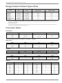
Conversion Tables
Energy units
Unit
A
kWh
kcal
1 J = 1 Nm = 1 Ws
1
2.778 * 10-7
2.39 * 10-4
1 kWh
3.6 * 106
1
860
1 kcal
4.187 * 103
1.163 * 10-3
1
Specific heat capacity of water: 1.163 Wh/kg K = 4.187 J/kg K = 1 kcal/kg K
Power units
Unit
kJ/h
W
kcal/h
1 kJ/h
1
0.2778
0.239
1W
3,6
1
0.86
1 kcal/h
4.187
1.163
1
Bar
Pascal
Torr
Water column
1
100.000
750 mm HG
10.2 m
Metre
Inch
Foot
Yard
1
39.370
3.281
1.094
0.0254
1
0.083
0.028
Pressure
Length
Powers
Prefix
Abbreviation
Denotation
Prefix
Abbreviation
Denotation
Deca
da
101
Deci
d
10-1
Hecto
h
102
Centi
c
10-2
Kilo
k
3
Milli
m
10-3
6
Micro
μ
10-6
9
Nano
n
10-9
Mega
Giga
M
10
10
G
10
Tera
T
1012
Pico
p
10-12
Peta
P
1015
Femto
f
10-15
Exa
E
1018
Atto
a
10-18
www.dimplex.de
9
1
1 Selection and Design of Heat Pumps
1.1
1.1.1
Design of Existing Heating Systems - Heat Pumps for the Renovation
Market
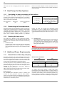
Heat consumption of the building to be heated
In the case of existing heating systems, the heat consumption of
the building to be heated must be recalculated because the
existing boiler cannot serve as a gauge for the actual heat
consumption. Boilers are - as a rule - overdimensioned and
therefore produce a heat pump output which is too large. The
actual heat consumption is calculated according to the
respective national standards (e.g. EN 12831). However, an
approximate estimate can be made on the basis of the existing
energy consumption of the living space to be heated and the
specific heat demand.
2LOFRQVXPSWLRQ>OD@
4 1
>ODN:@
1.1.2
1DWXUDOJDVFRQVXPSWLRQ
4 1
>PD@
>PDN:@
The specific heat consumption for detached and semi-detached
homes built between 1980 and 1994 is around 80 W/m2. For
homes built before 1980 in which no additional heat-insulation
measures have been carried out, it is between 100 W/m2 and
120 W/m2. In existing systems, the actual state of the system
must be taken into consideration.
NOTE
>N:@
In exceptional cases in which the actual consumption deviates widely
from the norm, approximate estimates can also deviate greatly from exact
calculations carried out according to the accepted standards.
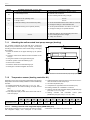
Determining the required flow temperature
In most oil and gas boiler systems the thermostat is set to a
temperature ranging from 70 °C to 75 °C. As a rule, this high
temperature is only required for preparing domestic hot water.
Downstream regulator systems within the heating system such
as mixing and thermostat valves prevent the building from
overheating. If a heat pump is retrofitted, it is imperative to
calculate the actual flow and return temperatures required so that
the correct renovation measures can be determined.
There are two ways of doing this.
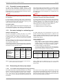
a)
The heat consumption calculation and the heat
consumption of each room are known.
The output according to the respective flow and return
temperatures is listed in the heat output tables for the
radiators (see Table 1.1 on p. 10). The room for which the
highest temperature is required determines the maximum
flow temperature in the heating system.
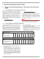
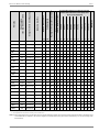
Cast iron radiators
Height
mm
Depth
mm
70
160
220
110
160
220
160
220
250
50 °C
45
83
106
37
51
66
38
50
37
60 °C
67
120
153
54
74
97
55
71
55
70 °C
90
162
206
74
99
129
75
96
74
80 °C
111
204
260
92
126
162
93
122
92
Heat output per element in W,
at mean water temperature Tm
980
580
430
280
Steel radiators
Height
mm
Depth
mm
110
160
220
110
160
220
160
220
250
50 °C
50
64
84
30
41
52
30
41
32
60 °C
71
95
120
42
58
75
44
58
45
70 °C
96
127
162
56
77
102
59
77
61
80 °C
122
157
204
73
99
128
74
99
77
Heat output per element in W, at mean
water temperature Tm
Fig. 1.1:
b)
10
>N:@
1000
600
Heat output of radiator elements (at a room temperature of ti=20 °C, according to DIN 4703)
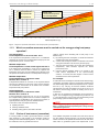
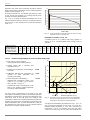
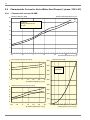
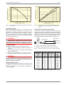
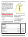
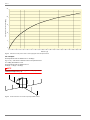
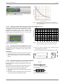
Experimental determination during the heating period
(see Fig. 1.2 on p. 11)
The flow and return temperatures are continually reduced
during the heating period with the thermostat valves fully
open until a room temperature of approx. 20-22 °C is
reached. Once the desired room temperature has been
reached, the actual flow and return temperatures plus the
external temperature are noted and entered in the diagram
shown below. The actual required temperature level (low,
medium, or high temperature) can be read from the entered
value using this diagram.
450
300
Selection and Design of Heat Pumps
1.1.4
+RWZDWHUIORZWHPSHUDWXUH&
)ORZWHPSHUDWXUH+7
)ORZWHPSHUDWXUH07
)ORZWHPSHUDWXUH/7
([DPSOHYDOXH
&H[WHUQDOWHPSHUDWXUH
&IORZWHPSHUDWXUH
+7+LJKWHPSHUDWXUH
&WR&
070HGLXPWHPSHUDWXUH
&WR&
/7/RZWHPSHUDWXUH
&
([WHUQDOWHPSHUDWXUHLQ>&@
Fig. 1.2:
1.1.3
Diagram for experimental determination of the actually required system temperatures
Which renovation measures must be carried out for energy-saving heat pump
operation?
Low-temperature
Flow temperature for all rooms max. 55 °C
yields a savings when retrofitting with a heat pump in four
different ways.
If the required flow temperature is below 55 °C, no additional
measures are required. Any low-temperature heat pump for flow
temperatures up to 55° C can be used.
a)
By reducing the heat consumption, a smaller and therefore
cheaper heat pump can be installed.
b)
Medium-temperature
Flow temperature in some rooms higher than 55 °C
A lower heat consumption leads to a reduction in the annual
energy demand which must be met by the heat pump.
c)
If the required flow temperature in some rooms is higher than
55 °C, measures must be taken to reduce the required flow
temperature. In this case, only the radiators in the affected rooms
are replaced to enable the use of a low-temperature heat pump.
The lower heat consumption can be met with reduced flow
temperatures, which therefore improves the annual
performance factor.
d)
Improved thermal insulation leads to an increase in the
mean surface temperatures of the space-enclosing
surfaces. As a result, the same degree of comfort can be
achieved at lower room temperatures.
Medium-temperature
Flow temperatures in almost all rooms
between 55 °C and 65 °C
If temperatures between 55 °C and 65 °C are required in almost
all rooms, the radiators in most of the rooms must be replaced.
As an alternative, the decision can be made to use a mediumtemperature heat pump instead.
High-temperature
Flow temperatures in almost all rooms
between 65 °C and 75 °C
If flow temperatures ranging from 65 °C to 75 °C are required,
the complete heating system must be converted or adapted. If it
is not possible or not desirable to carry out such a conversion, a
high-temperature heat pump must be installed instead.
A reduction in heat consumption achieved by
replacing windows
reducing ventilation losses
For example:
A house with a heat consumption of 20 kW and an annual energy
consumption for heating of approx. 40,000 kWh is heated with a
hot water heating system with a flow temperature of 65 °C (return
flow 50 °C). By carrying out thermal insulation measures
retrospectively, the heat consumption can be cut by 25 % to 15
kW and the annual energy demand for heating can be cut to
30,000 kWH.
In this way, the required flow temperature can be lowered by
approx. 10 K, cutting the energy consumption by a further 20 - 25
%. The total savings in energy costs when implementing a heat
pump heating system amounts to approx. 44 %.
NOTE
The following generally applies for heat pump heating systems:
Every 1°C reduction in the flow temperature yields a savings in energy
consumption of approx. 2.5 %.
insulating ceiling spaces, attics and/or facades
1.1.4
Choice of heat source (renovation)
It is rarely possible to install a ground heat collector, borehole
heat exchanger or well system in the renovation market for
existing houses with landscaped gardens. In most of the cases,
the outside air is the only possible heat source.
www.dimplex.de
Air is available everywhere as a heat source and can be used at
any time without requiring approval. The annual performance
factors which are to be expected are lower than is the case when
either water or geothermal systems are implemented. At the
11
1.2
same time, the costs for tapping the heat source system are
lower.
1.2
1.2.1
Refer to the relevant chapters for further information on how to
dimension heat source systems for brine-to-water and water-towater heat pumps.
Heat Pumps for New Systems
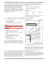
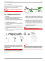
Calculating the heat consumption of the building
The maximum hourly heat consumption 4his calculated
according to the respective national standards. It is possible to
approximately estimate the heat consumption using the living
T = 0.03 kW/m2
space A (m2) that is to be heated:
+HDWFRQVXPSWLRQ
>N:@
+HDWHGVSDFH
>P@
 VSHFLILFKHDWUHTXLUHPHQW
>N:P@
Low-energy house
T = 0.05 kW/m
Acc. to thermal insulation ordinance 95 and/
or the EnEV minimum insulation standard
T = 0.08 kW/m2
For a house with normal thermal insulation
(built approx. in 1980 or later)
T = 0.12 kW/m2
For older walls without special thermal
insulation
2
Table 1.1: Estimated specific heat consumption values
1.2.2
Determining the flow temperatures
When dimensioning the heat distribution system of a heat pump
heating system, it should be borne in mind that the required heat
consumption should be assigned on the basis of the lowest
possible flow temperatures, because every 1 °C reduction in the
flow temperature yields a savings in energy consumption of
approx. 2.5 %. Extensive heating surfaces, e.g. underfloor
1.2.3
Selecting the heat source
The decision as to whether air, brine (ground heat collector,
borehole heat exchanger) or water (well system) should be used
as the heat source should be made on the basis of the following
factors.
a)
Investment costs
In addition to the costs for the heat pump and the heating
system (radiators and circulation pump), the investment
costs are heavily influenced by the costs of tapping the heat
source.
1.3
1.3.1
b)
Operating costs
The expected annual performance factors of the heat pump
heating system have a large influence on the operating
costs. These are primarily affected by the type of heat pump,
the average heat source temperature and the required
heating flow temperatures.
NOTE
The annual performance factors which can be expected for air-to-water
heat pumps are lower than for water and geothermal systems. However,
the costs for tapping the heat source system are also lower.
Additional Power Requirements
Shut-off times of the utility company
Most utility companies offer special agreements with a lower
electricity tariff if heat pumps have been installed. According to
the German Federal Tariff Ordinance, the utility company may
offer such an agreement if it is able to switch off and block heat
pumps at times of peak demand in the supply network.
The heat pump is then no longer available for heating the house
during these shut-off times. Therefore, surplus energy must be
produced during the periods in which the heat pump is not
available for use. Hence, the heat pump should be
overdimensioned to allow for this.
Utility company shut-off times normally last up to 4 hours a day,
which must be allowed for with a factor of 1.2.
Dimensioning
The calculated heat consumption values for heating and
domestic hot water preparation should be added together.
Unless a second heat generator is additionally used during the
shut-off time, the sum of the heat consumption values must be
multiplied by the dimensioning factor f:
12
heating, are ideal. The required flow temperature should
generally be 55 °C max. to enable the use of low-temperature
heat pumps. If higher flow temperatures are necessary, medium
or high-temperature heat pumps must be used (Chap. 1.1.3 on p.
11).
Basis of the calculation:
I
K
K
(QDEOHSHULRG
KVKXWRIIWLPH
Blocking time (total)
Dimensioning factor
2h
1.1
4h
1.2
6h
1.3
Table 1.2: Dimensioning factor f for taking shut-off times into consideration
The existing heat storage capacity of solidly built houses,
particularly those with underfloor heating, is normally sufficient to
also bridge longer shut-off times with only a small loss of comfort
so that it is not necessary to use a second heat generator (e.g.
boiler). However, an increase in output of the heat pump is
necessary because of the need for reheating the storage mass.
Selection and Design of Heat Pumps
1.3.2
1.3.4.1
Domestic hot water preparation
To meet normal requirements regarding comfort, a peak
domestic hot water consumption of approx. 80-100 litres per
person and per day must be reckoned with based on a hot water
temperature of 45 °C. In this case, allowance should be made for
a heat output of 0.2 kW per person.
pipes and the quality of the pipe insulation. If a circulation system
cannot be dispensed with because of long pipe runs, a circulation
pump should be used that can be activated by a flow sensor
according to need. Heat consumption for a circulation pipe can
be considerable.
NOTE
NOTE
The maximum possible number of persons should be assumed when
dimensioning and any special usage (e.g. whirlpool) should also be taken
into consideration.
To be in compliance with Paragraph 12 (4) of the German Energy
Efficiency Ordinance, circulation pumps in hot water systems must be
equipped with an automatic switch-on/switch-off mechanism.
It is not necessary to add the hot water energy consumption to
the heat consumption of the heating system if domestic hot water
is heated with the flange heater at the time of year (e.g. midwinter) used as the basis for the calculation.
The surface-related heat loss of the domestic water distribution
system depends on both the surface area and the position of the
circulation pipework. For a surface area ranging from 100 to
150m and distribution within the thermal envelope, the surfacerelated heat losses according to the German EnEV are:
Circulation pipes
Circulation pipes increase the line-side heat consumption of the
domestic hot water heating. This increase in consumption that is
to be allowed for depends on both the length of the circulation
1.3.3
9.8 [kWh/m2a] with a circulation system
4.2 [kWh/m2a] without a circulation system
Hot water heating for a swimming pool
Outdoor swimming pool
For initially heating the pool to a temperature of over 20 °C, the
The heat consumption for heating the water in an outdoor
swimming pool depends strongly on the respective usage.
quantity of thermal energy required is approx. 12 kWh/m3 pool
volume. Heating-up periods ranging from one to three days are
required depending on the size of the pool and the output of the
installed heating system.
In terms of size, it can easily be the same as the heat
consumption of a house - and in such cases must be calculated
separately.
However, if heating is only carried out in the summertime (period
not requiring heating), the heat consumption mentioned above
can be ignored in certain cases.
An approximate estimation of the heat consumption is dependent
on the windage factor, the climatic conditions, the periods of use
and whether or not the pool has a cover.
20 °C
Water temperature
24 °C
28 °C
With cover1
100 W/m2
150 W/m2
200 W/m2
Without cover
Sheltered location
200 W/m2
400 W/m2
600 W/m2
Without cover
Partly sheltered
location
300 W/m2
500 W/m2
700 W/m2
Without cover
Unsheltered location
(subject to high winds)
450 W/m2
800 W/m2
Indoor swimming pool
Space heating
Space heating is carried out using radiators or underfloor
heating and/or a heat exchanger in the dehumidification/
ventilation system. In both cases it is necessary to calculate
the heat consumption - according to the system installed.
Hot water heating for a swimming pool
The heat consumption depends on the pool temperature,
the temperature difference between the pool temperature
and the room temperature, and the pool usage.
Room
temperature
1,000 W/m2
1. Reduced values for pools with a cover only refer to private swimming pools
used on average up to 2 h per day.
Table 1.3: Reference values for the heat consumption of outdoor swimming
pools used between May and September
90 W/m2
165 W/m2
265 W/m2
25 °C
2
65 W/m
140 W/m
2
240 W/m2
28 °C
20 W/m2
100 W/m2
195 W/m2
These outputs can be reduced by up to 50 % for private
swimming pools with a cover that are used for a maximum of 2
hours per day.
Determining the heat pump output
1.3.4.1
Air-to-water heat pump (mono energy operation)
www.dimplex.de
23 °C
Table 1.4: Reference values for the heat consumption of indoor swimming
pools
1.3.4
Air-to-water heat pumps are primarily operated in mono energy
systems. The heat pump should fully meet the heat consumption
down to an external temperature (bivalence point) of approx.
-5 °C. In the event of very low temperatures and high heat
consumption, a second, electrically operated heat generator will
be activated.
Water temperature
20 °C
24 °C
28 °C
In the case of mono energy systems, dimensioning of the heat
pump output has a particularly strong influence on the level of the
investment and the annual heating costs. In most cases, the
higher the heat pump output, the higher the initial investment and
the lower the annual heating costs will be.
13
1.3.4.2
Experience has shown that a heat pump should be selected
which cuts the heating characteristic curve for a limit temperature
(bivalence point) of approx. -5 °C.
([WHUQDOWHPSHUDWXUHLQ>&@
According to the DIN 4701 T10 standard, this yields a 2 % ratio
for the second heat generator (e.g. heating element) when
operated as a bivalent-parallel system.
Fig. 1.3 on p. 14 shows the annual characteristic curve of the
external temperature in Essen, Germany. According to this, there
are less than 10 days annually with an external temperature
under -5 °C.
7LPHLQGD\V
Fig. 1.3:
Annual characteristic curve: Number of days on which the external
temperature is below the specified value
Example for Table 1.5 on p. 14:
A bivalence point of -5 °C yields a heat pump proportion of
approx. 98 % for a bivalent-parallel (mono energy) mode of
operation.
Bivalence point [°C]
-10
-9
-8
-7
-6
-5
-4
-3
-2
-1
0
1
2
3
4
5
Coverage ratio [-] for
biv.-paral. operation
1.00
0.99
0.99
0.99
0.99
0.98
0.97
0.96
0.95
0.93
0.90
0.87
0.83
0.77
0.70
0.61
Coverage ratio [-] for
biv.- altern. operation
0.96
0.96
0.95
0.94
0.93
0.91
0.87
0.83
0.78
0.71
0.64
0.55
0.46
0.37
0.28
0.19
Table 1.5: Coverage ratio of the heat pump of a mono energy system or a system operated as a bivalent system according to bivalence point and mode of operation
(source: Table 5.3-4 DIN 4701 T10)
1.3.4.2
Dimensioning example for an air-to-water heat pump
Mono energy mode of operation:
Heat pump with electric heating element
Selected heat consumption of the building to
be heated
9.0 kW
Additionally selected heat consumption for
domestic hot water preparation and
swimming pool heating
1.0 kW
(heat consumption of the building +
additional heat consumption) x factor f from
Table 1.2 on p. 12 (with e.g. a 2-h shut-off
time) = (9.0 kW + 1 kW) x 1.1 =
11.0 kW
= required heat output of the heat pump on the
basis of the standard outside temperature
according to national standards.
+HDWLQJFDSDFLW\LQ>N:@LQFOGHIURVWLQJ
+3
Heating system with a maximum flow
temperature of 35 °C
+3
5HTXLUHGDGGLWLRQDORXWSXW
3W
+HDWFRQVXPSWLRQRIWKHEXLOGLQJGHSHQGHQW
RQRXWVLGHWHPSHUDWXUHVLPSOLILHG
3W
The heat pump is dimensioned on the basis of the heat
consumption of the building in relation to the outside temperature
(simplified as a straight line) in the heat output diagram and the
heat output curve of the heat pump. The building's heat
consumption in relation to the external temperature is entered on
the basis of the selected room temperature (corresponding to the
external temperature point 1) on the horizontal axis (x axis) for
the calculated heat output (point 2) for the standard external
temperature according to national standards.
14
%LYDOHQFHSRLQW
Fig. 1.4:
([WHUQDOWHPSHUDWXUHLQ>&@
Heat output curves for two air-to-water heat pumps with different
heat outputs for flow temperatures of 35 °C and a building heat
consumption in relationship to the outside temperature
The approach is illustrated by the example from Fig. 1.4 on p. 14
with a total heat consumption for the house of 11.0 kW at a
standard outside temperature of -16 °C and a selected room
temperature of +20 °C. The diagram shows the heat output
curves of two heat pumps at a hot water flow temperature of
Selection and Design of Heat Pumps
1.3.4.4
35 °C. The intersection points (limit temperature or bivalence
point) of the straight line of the heat consumption of the building
in relation to the outside temperature and the heat output curves
of the heat pumps are approx. -5.0 °C for HP 1 and approx. -9 °C
for HP 2. HP 1 would be used for the selected example.
A
supplementary electric heating system is used to enable yearround heating. This compensates for the difference between the
heat consumption of the building in relation to the outside
temperature and the heat output of the heat pump for the
corresponding air intake temperature.
Design of the supplementary electric heating
system:
Total heat consumption on the coldest day
– Heat output of the heat pump on the coldest day
= Output of the heating elements
For example:
N:
±
+HDWFRQVXPSWLRQ
RIWKH
EXLOGLQJDW
&
N:
N:
+HDWRXWSXW
RIWKH+3DW
&
2XWSXWRIWKH
KHDWLQJHOHPHQWV
HP 1 should be dimensioned with a heating element that has an
electrical output of 6.0 kW for the selected example.
1.3.4.3
Water-to-water and brine-to-water heat pumps (monovalent operation)
Total calculated heat consumption
= _____kW
+HDWLQJFDSDFLW\LQ>N:@
+HDWSXPSW\SH
= Heat output of the heat pump
+3
for W10 /W351 or BO/W351
1. For monovalent systems, dimensioning should be based on both the
maximum flow temperature and the minimum heat source temperature!
&RQGLWLRQV
+HDWLQJZDWHURXWOHWWHPSHUDWXUH:
NOTE
Refer to the operating instructions of the respective device for the actual
heat outputs of water-to-water and brine-to-water heat pumps at each
respective flow temperature.
+3
For example:
Monovalent operation for a heating system
with a maximum flow temperature of 35 °C.
+3
Selected heat consumption of the house to be
heated
+3
10.6 kW
+3
Heat consumption of the house and
components x factor f from Table 1.2 on p. 12
(for e.g. a 6 h shut off time; f = 1.3) = fictitious
total heat consumption.
Total heat consumption= 10.6 kW x 1.3
3W
+3
= 13.8 kW
= Heat output of the heat pump
Fig. 1.5 on p. 15 shows the heat output curves of brine-to-water
heat pumps. The heat pump to be selected is the one having a
heat output which is above the intersection of the required total
heat consumption and the temperature of the available heat
source.
+3
%ULQHLQOHWWHPSHUDWXUHLQ>&@
Fig. 1.5:
Heat output curves of brine-to-water heat pumps with different heat
outputs for flow temperatures of 35 °C.
The output curve of HP 5 must be selected for a maximum
required flow temperature of 35 °C for a total heat consumption
of 13.8 kW and a minimum brine temperature of 0 °C. This yields
a heat output of 14.5 kW for the above boundary conditions.
1.3.4.4
Water-to-water and brine-to-water heat pumps (mono energy operation)
Mono energy brine-to-water or water-to-water heat pump
systems are equipped with a second electrically operated heat
generator, e.g. a buffer tank with an electric heating element.
Mono energy brine-to-water or water-to-water heat pump
systems should only be planned in exceptional circumstances if
shut-off times mean that large quantities of power must be drawn
www.dimplex.de
from the grid or if, on account of the available device range, a
heat pump must be selected which has a considerably larger
output in comparison to the total heat consumption. Mono energy
operation is also particularly suitable for the first heating period if
the building is dried out in autumn or in the winter.
15
1.3.4.5
Heat pump output
Heat source variables
The heat output should be dimensioned for a limit temperature
below -10 °C. This yields a heat pump output of 75 % to 95 %
measured as a percentage of the total heat consumption based
on the lowest external temperature.
When using earth energy as the heat source (ground source),
the ground heat collector or borehole heat exchanger should be
dimensioned on the basis of the total heat consumption to ensure
that any formation of ice thaws in the spring. When dimensioning
the well for water-to-water heat pumps, no further requirements
for mono energy operation need to be taken into consideration
apart from standard design criteria.
1.3.4.5
Air-to-water heat pump (bivalent operation)
When a system is operated as a bivalent-parallel system
(existing older building), a second heat generator (oil or gas
boiler) assists the heat pump from the bivalence point of < 4 °C.
It is often useful to select a smaller sized heat pump since the
heat pump's percentage of annual heat output fluctuates very
little. A prerequisite is that long-term operation of a bivalent
system is planned.
1.3.4.6
Water-to-water and brine-to-water heat pumps (bivalent operation)
The same interrelationships generally apply for bivalent
operation of water-to-water and brine-to-water heat pumps as for
air-to-water heat pumps. However, other dimensioning factors
1.3.4.7
must be considered depending on the layout of the heat source
system.
Ask our heat pump system specialists if you have any questions
on this topic.
Drying-out of buildings
When a house is being built, large quantities of water are
normally used for mortar, rendering, plaster and wall paper,
which only evaporates very slowly from the building. In addition,
rain can decisively increase the humidity in the building's
structure. This increased humidity in the entire structure causes
an increase in the heat consumption of the house during the first
two heating periods.
For this reason, buildings should be dried out using specially
designed dehumidifiers. Particularly if brine-to-water heat pumps
are implemented, we recommend installing an additional heating
element to compensate for the increased heat consumption if the
16
NOTE
Experience has shown that, in the case of bivalent systems used in
modernisation projects, the existing oil or gas boiler will be taken out of
service after a few years, for a variety of reasons. Therefore,
dimensioning should always be carried out analogue to the mono energy
system (bivalence point is approx. -5 °C). At the same time, the buffer
tank should also be integrated into the heat flow.
heat outputs of the heat pump have been marginally calculated
and the respective building is to be dried out in autumn or in the
winter. In the case of brine-to-water heat pumps, this heating
element should then only be activated during the first heating
period on the basis of the brine flow temperature (approx. 0 °C)
or on the basis of the limit temperature (0 °C to 5 °C).
NOTE
In the case of brine-to-water heat pumps, the increased compressor
runtimes could cause the heat source to supercool in turn causing the
heat pump to automatically switch off.
Air-to-Water Heat Pumps
2
2.2.1
Air-to-Water Heat Pumps
2.1
The Air as Heat Source
Area of application of air-to-water heat pumps
-25 °C... + 35 °C
Availability of outside air as a heat source
Unlimited
Types of operation
have a minimum diameter of 50 mm and should be fed into the
sewer for rain water to ensure that large quantities of water can
be drained off. Defrosting takes place up to 16 times daily, with
up to 3 litres of condensed water being produced each time.
ATTENTION!
Bivalent-parallel (partial-parallel)
If the condensation is fed into clearing tanks and sewage systems a
siphon is required in order to protect the evaporator from damaging
vapours.
Alternative bivalent mode
Recommended Installation
Mono energy
Bivalent-renewable mode
Buffer tank
The integration of the air-to-water heat pump requires a buffer
tank connected in series to ensure that the evaporator (finned
heat exchanger) is defrosted by means of reverse circulation.
Installation of a buffer tank connected in series also lengthens
the runtimes of the heat pump during periods of reduced heating
demand (see Chap. 8.5 on p. 180).
Condensate outflow
Condensed water that forms during operation must be drained
off frost-free. The heat pump must be mounted on a level plane
to guarantee proper drainage. The condensed water pipe must
2.2
The air-to-water heat pump should preferably be installed
outdoors. This is a simple, economical installation option
because the requirements placed on the foundations are minimal
and this set-up avoids the need for air ducting. If outdoor
installation is not possible, it should be kept in mind that
condensation can form on the heat pump, on air ducts and
especially around wall openings when the heat pump is installed
in rooms with high humidity.
ATTENTION!
The intake air must not contain ammonia. The use of air from animal
stables is therefore not permitted.
Air-to-Water Heat Pumps for Indoor Installation
Costs for indoor installation
Air circuit (e.g. ducting)
Wall openings
Condensate outflow
General information
An air-to-water heat pump should not be installed in the living
quarters of a building. In extreme circumstances, outside air as
cold as -25 °C may pass through the heat pump. This can lead to
the formation of condensation in the area around wall openings
and air duct connections in rooms with high humidity, e.g.
kitchens and laundry rooms, eventually resulting in damage to
the building. The formation of condensation cannot be avoided
(evenwith good thermal insulation) if the ambientair humidity
exceeds 50 % and the external temperature is below 0 °C.
Therefore, unheated rooms such as cellars, storerooms, and
garages are more suitable installation locations.
NOTE
If the heat pump is installed on an upper storey, the load-bearing
capacity of the ceiling should be checked. Installation on a
wooden floor is not recommended.
NOTE
If the heat pump is installed above inhabited rooms, constructional
measures for solid-borne sound insulation are required.
Air circuit
Air-to-water heat pumps installed indoors must be supplied with
a sufficient air volume flow to ensure efficient and smooth
operation. This is based primarily on the heat output of the heat
pump and is between 2,500 and 9,000m3/h (see Chap. 2.6 on p.
28). The minimum dimensions for the air ducting must be
observed.
Air circulation from the air intake through the heat pump to the air
outlet should be as unhindered as possible so that any
unnecessary air resistance is avoided (Chap. 2.3 on p. 21).
For a higher degree of sound protection, the air outlet should be over a
90° bend or outdoor installation should (Chap. 2.4 on p. 24) be selected.
2.2.1
Requirements placed on the installation location
Ventilation
The room in which the heat pump is installed should preferably
be ventilated with outside air so that the relative humidity level
remains low and the formation of condensate is avoided.
Condensate can form on cold components in particular during
start-up of the system and when the building is being dried out.
www.dimplex.de
ATTENTION!
The heat pump must not be operated without appropriate air circulation
because of the risk of injury caused by rotating parts (ventilator).
17
2.2.2
2.2.2
Air intake and air outlet via light wells
If the wall openings for the air ducting on either the air intake or
air outlet are positioned below ground level, it is recommended
that the air circuit is routed through plastic light wells which do not
impede the air flow. A cowling must be installed if the wells are
made of concrete.
DSSUR[
The minimum light well dimensions are 1000x400 mm
(Refer to the device information for the minimum dimensions
for the air ducting if 2 compressors are installed)
The transition between the light well and the wall opening
(see Chap. 2.2.4 on p. 18) should be sealed
The light well should be covered with a grating (safeguarded
against burglary)
An outlet for condensate must be provided
A wire grating (0.8 cm > mesh size) should be fitted to
prevent small animals from entering and leaves from falling
in.
2.2.3
Fig. 2.1:
Air inlet openings - light well
Fig. 2.2:
Heat pump rain guard
Heat pump rain guard
Rain guards act as a visual covering for wall openings above
ground and also protect the air ducting from the effects of the
weather. They are mounted on outside walls and can therefore
be used independent of the type of air circuit. The rain guard
(special accessory) has been specially developed for heat
pumps and features a significantly lower pressure drop than
standard rain guards. It can be used either on the air intake or
the air outlet side.
A wire grating should be fitted between the wall and the rain
guard to prevent small animals from entering and leaves from
falling in. At least 80 % of the grating’s cross section mustbe
open (mesh size > 0.8cm). Measures to safeguard the rain guard
against burglary are to take place on site.
Item
Description
500-700
800
1
Rain guard
1 item
1 item
2
Dowel 6 x 30
4 items
6 items
3
Screw 5 x 70
4 items
6 items
Insulation of wall openings
Necessary wall openings should be provided on site. It is
essential that the interior side of the wall opening in lined with
thermal insulation to prevent the wall from becoming cold and to
prevent moisture from penetrating the wall. For example, Fig. 2.3
on p. 18 illustrates insulation using rigid polyurethane foam (25mm insulation thickness). The transition between the wall
insulation and the wall-mounted junction box must be sealed airtight. Water which has penetrated due to adverse weather
conditions (e.g. driving rain) should be routed outside by means
of a gradient.
:DOO
DSSUR[
2.2.4
Fig. 2.3:
18
5LJLGSRO\XUHWKDQHIRDP
'XFWFRQQHFWLQJSLHFH
Example of how to construct the wall opening
Air-to-Water Heat Pumps
2.2.5
2.2.5
Air-to-water heat pumps in a compact design for indoor installation
In addition to the heat source, with compact air-to-water heat
pumps the components for direct connection of an unmixed
heating circuit are integrated.
Heat pump managers
Air circuit diverted at a 90° angle or on walls
Overflow valve and safety components
The heat pump allows for installation in a corner without
additional ducts. Wall installation is also possible in combination
with an air duct on the air outlet side.
Buffer tank
Expansion vessel (24 litre, 1.0 bar admission pressure)
Heat circulating pump
Supplementary electric heating system 2 kW
The base frame must rest on a smooth, even and level surface.
The heat pump must be installed so that maintenance work can
be carried out without hindrance. This can be ensured by
maintaining a clearance of 1 m in front and to the left of the heat
pump.
The air intake opening of the device is designed for direct
connection to a wall opening. This is done by attaching the selfadhesive sealing ring supplied and gently pushing the device
against the wall. It is essential that the interior side of the wall
opening is lined with thermal insulation (see Fig. 2.4 on p. 19) to
prevent the wall from becoming cold and to prevent moisture
from penetrating the wall (i.e. rigid polyurethane foam/aluminium
foil)
The air outlet can be optionally mounted directly to a wall
opening or to one of the GRC ducts available as accessories
(see Fig. 2.4 on p. 19 and Fig. 2.5 on p. 19).
The following air circuit components are available for compact
air-to-water heat pumps.
RSG 500 rainguard
Air ducts (LKL, LKB, LKK 500)
DMK 500 sealing collar
Please observe the notes in Chap. 2.2.5 on p. 19 when using the
GRC air ducts available as accessories.
1)
Evaporator
7)
Switch Box
2)
Ventilator
8)
Filter dryer
Basic Device
3)
Liquefier
9)
Inspection window
The heat pump is supplied complete with all of the important
components of the heating circulation system:
4)
Compressor
10) Buffer tank
5)
Heat circulating pump
11) Expansion valve
6)
Expansion vessel 24 l
12) Overflow valve
Installation example
%HORZJURXQGOHYHO
%HORZJURXQGOHYHO
/LJKWZHOO
/LJKWZHOO
$GDSWRU
5DLQJXDUG
$GDSWRU
5HGXFLEOH
$FFHVVRULHV
5HGXFLEOH
$ERYHJURXQGOHYHO
FXWOHQJWK
5DLQJXDUG
&XWOHQJWK
&RQGHQVDWHRXWIORZ
'LUHFWLRQRIDLUIORZ
$ERYHJURXQGOHYHO
&RQGHQVDWHRXWIORZ
$FFHVVRULHV
'LUHFWLRQRIDLUIORZ
2SHUDWLQJVLGH
2SHUDWLQJVLGH
$GDSWRU
5HGXFLEOH
6HDOLQJFROODU
$FFHVVRULHV
$GDSWRU
5HGXFLEOH
Fig. 2.4:
Corner installation 500 with wall opening insulated on site. An
adaptor (duct section) can also be used as insulation (Fig. 2.11 on
p. 57)
www.dimplex.de
Fig. 2.5:
Wall installation 500 with GRC air duct
19
2.2.6
2.2.6
Air duct hose set for air-to-water heat pumps (indoor installation)
Flexible hoses are offered as accessories for the air circuit for the
air-to-water heat pumps LI 11TE and LI 16TE. The air duct hose
set is suitable for use in rooms with low temperatures and low
humidity. It contains a 5m length of thermally-insulated and
sound-insulated air hose which can be used for both the air
intake and the air outlet side. Air intake and air outlet can take
place via a light well or a rain guard. Installation material for
connection to the heat pump and for the wall opening to be
insulated on site is included.
Air hoses have the advantage that they can be individually
adapted on site and are able to simply and quickly compensate
for height and length differences. In addition, air hoses have both
a thermal and sound insulating effect and prevent the room in
which the system is installed from becoming cold. A grid on the
wall connection stubs prevents small animals from entering and
leaves from falling in.
NOTE
The minimum air flow should be checked if there is a 90° air deflection on
either the air intake or the air outlet side.
Dimensions in
mm
DN 500
DN 630
652
A
560
B
585
670
ØC
495
625
D
100
100
Table 2.1: Dimensions of the air duct hose set
Scope of supply
1)
Heat pump
connecting stubs
2)
Hexagon bolt
3)
Connection clamp
4)
Hexagon bolt
5)
Perforated steel ribbon
6)
Dowel
7)
Connecting hose with
insulation thickness of 25 mm
8)
Screw
9)
Connecting
mounted)
stubs
(wall-
10) Dowel
Minimum bend radius LUS 11:
300 mm
Minimum bend radius LUS 16:
400 mm
Space requirement for 90° bend:
approx. 1 m
Fig. 2.6:
2.2.7
Air duct hose set
GRC air ducts for air-to-water heat pumps (indoor installation)
The glass fibre reinforced concrete air ducts offered as
accessories are moisture-resistant and diffusion-free. They are
supplied in each respective cross section as 90° bends and as
625 mm and 1,250mm extensions.
,QVXODWLQJVWULS
Fig. 2.7:
,QVXODWLQJVWULSDSSUR[
Minor damage to the outer surface has no affect on the efficiency
and can be repaired with standard plaster.
6XSSRUWLQJIHHWDSSUR[
0LQURRPKHLJKW&
$
2SHUDWLQJVLGH
'HYLFHKHLJKW+
&RQGHQVDWHRXWIORZ
PD[
'UDLQ
The ducts can be painted with standard emulsion paint according
to need.
20
'LUHFWLRQRIDLUIORZ
%
The formation of condensate is avoided due to the internal
insulation consisting of mineral wool and foil-clad glass fibre mat,
resulting in a clear reduction in sound transmissions. The ends
are fitted with zinc-plated pressed steel frames.
%XIIHUWDQN
Air-to-water heat pumps with GRC air ducts and built-under buffer
tank
Air-to-Water Heat Pumps
2.3
Assembly of a standard installation set-up:
Cutting lengths:
Air ducts can be mounted as delivered if a standard installation
set-up (see Chap. 2.3.1 on p. 22) is selected.
Existing air ducts can be shortened or adapted on site using the
conversion kit available as an accessory. The resulting cut edges
are coated with a suitable adhesive paste (i.e. silicon) and the
ends are then fitted with zinc-plated channel sections.
The minimum clearances from the heat pump to the walls (see
Fig. 2.8 on p. 21) should always be observed when positioning
the air circuit.
The air ducts or bends are sealed in the wall opening with
standard polyurethane foam in accordance with the dimensions
in the drawing. The ducts are supported at regular intervals from
below or using threaded rods from the ceiling.
NOTE
For solid-borne sound insulation, the air ducts are not screwed directly
onto the heat pump.
A clearance of approx. 2cm should be left between the heat
pump and the ducting to simplify future disassembly of the heat
pump. The seal to the heat pump is made with the sealing collar
which is available as an accessory (see Fig. 2.9 on p. 21).
Butt joint between two duct sections:
When determining where to make the cut, it should be noted that
straight ducts are equipped with the tab required for connection
at one end only.
The duct sections can be cut with standard woodworking tools
such as e.g. a circular saw or jigsaw. Carbide or diamond-tipped
tools are recommended.
Sealing collar
The sealing collar is used to seal the glass fibre reinforced
concrete air ducts on the heat pump. The air ducts are not
screwed directly onto the heat pump. Only the rubber seal comes
into direct contact with the heat pump when the system is
installed correctly. This guarantees easy assembly and
disassembly of the heat pump and also ensures that solid-borne
sound is well insulated.
The duct sections are equipped with a metal fixing frame to
facilitate connection. Using these fixing frames for connection
avoids air turbulence and the resulting pressure drops.
The components are sealed off from one another by gluing
standard foam rubber between the metal frames or by applying
silicon sealant between the metal frames.
Fig. 2.9:
Fig. 2.8:
Minimum clearances for indoor installation of the air-to-water heat
pump
2.3
Dimensioning the Air Circuit
It should be borne in mind when dimensioning the air circuit (air
intake and air outlet) that the maximum pressure drop (max.
compression) of the individual components must not exceed the
value listed in the device information (see Chap. 2.6 on p. 28).
Both cross sectional areas which are too small and deflections
(e.g. rain guard) which are too extreme can cause impermissibly
high pressure drops and lead to ineffective or faulty operation.
Air circuit components
Pressure drop
Air duct straight
1 Pa/m
Air duct bend
7 Pa
Rain guard
5 Pa
Light well air intake
5 Pa
Light well air outlet
7-10 Pa
Table 2.2:Reference values for the air circuit system
accessories
www.dimplex.de
Sealing collar for air ducts
NOTE
The air circuit within the building should have a maximum of two 90°
deflections to ensure compliance with the maximum permissible
pressure drops.
The air circuit components available as special accessories are
designed such that their values are below the permissible
compressions for the standard installation set-ups shown (see
Chap. 2.3.1 on p. 22). This means that it is not necessary to
check the overall pressure drop. A light well or a wall opening
with a rain guard can be used for the air intake and air outlet.
The overall pressure drop, which is the sum of the individual
pressure drops from the air intake to the air outlet, must not
exceed the value given in the device information (see Chap. 2.6
on p. 28). Grids, light wells, tight bends, air ducting and air hoses
should also be taken into consideration.
21
2.3.1
ATTENTION!
Device type
Air circuit
components
LIK 8ME / LIK 8TE / LI 9TE
Type 500
LI 11ME / LI 11TE
Type 600
Selection of air circuit components
LI 16TE / LI 20TE
Type 700
The following air circuit components are available in four different
sizes to correspond to the available performance levels:
LI 24TE / LI 28TE
Type 800
LIH 22TE / LIH 26TE
Type 800
The minimum air flow should be checked whenever the set-up deviates
from the standard connections or third-party air circuit components are
fitted.
Rain guard
Table 2.3: Allocation of air circuit components
Air duct (duct/bend)
Sealing collars
Height dimensions for use of glass fibre concrete ducts
,QVXODWLQJVWULS
,QVXODWLQJVWULSDSSUR[
6XSSRUWLQJIHHWDSSUR[
$
2SHUDWLQJVLGH
0LQURRPKHLJKW&
&RQGHQVDWHRXWIORZ
PD[
'UDLQ
'HYLFHKHLJKW+
'LUHFWLRQRIDLUIORZ
%
2.3.1
%XIIHUWDQN
Fig. 2.10: Front view 600-800
Built-under buffer tank
The 140 litre built-under buffer tank is suitable for all LI 11TE,
LI 16TE and LI 20TE heat pumps installed indoors, because it
A (in mm)
with buffer
A (in mm)
without
buffer
LIK 8ME / LIK 8TE
–
LI 9TE
–
600
LI 11ME / LI 11TE
700
800
increases the overall height of the construction, allowing the air
ducts to be installed directly below the ceiling.
B (in mm)
C (in mm)
H (in mm)
with buffer
H (in mm)
without
buffer
1328
550
2100
–
1911
678
550
2100
–
1261
1282
672
650
2200
1981
1371
LI 16TE / LI 20TE
1340
730
745
2400
2191
1581
LI 24TE - LI 28TE /
LIH 22TE - LIH 26TE
–
762
820
2000
–
1721
Type
Heat Pump
500
500
Table 2.4: Table of dimensions for front view 600-800 (LIK 8TE / LI 9TE see Chap. 2.2.5 on p. 19)
The dimensions for the installation of the heat pump and the
position of the wall openings are determined as follows:
1. Step:
Determine the type of air circuit components
required depending on the type of air-to-water heat
pump to be installed according to Table 2.3 on p.
22.
2. Step:
Select the required installation version.
3. Step:
Extract the required values pertaining to the
respective installation version from the table of
dimensions.
22
Air-to-Water Heat Pumps
2.3.2
2.3.2
Installation in a corner
5DLQJXDUG
$FFHVVRULHV
$ERYHJURXQGOHYHO
%
'LUHFWLRQRIDLUIORZ
(
'
&RQGHQVDWHRXWIORZ
%
/LJKWZHOO
%HORZJURXQGOHYHO
DWOHDVW
2SHUDWLQJVLGH
PLQ
6HDOLQJFROODU
$FFHVVRULHV
Fig. 2.11: Corner installation (LIK 8TE / LI 9TE see Chap. 2.2.5 on p. 19)
Type
Heat Pump
B (in mm)
D1 (in mm)
E (in mm)
600
LI 11ME / LI 11TE
650
301
852
700
LI 16TE / LI 20TE
745
254
852
800
LI 24TE - LI 28TE /
LIH 22TE - LIH 26TE
820
291
1002
Table 2.5: Table of dimensions for installation in a corner
%HORZJURXQGOHYHO
/LJKWZHOO
%
PLQFXWOHQJWK
$GDSWRU
5DLQJXDUG
$FFHVVRULHV
'LUHFWLRQRIDLUIORZ
$ERYHJURXQGOHYHO
'
%
(
&XWOHQJWK
&RQGHQVDWHRXWIORZ
6HDOLQJFROODU
2SHUDWLQJVLGH
5HGXFLEOH
$FFHVVRULHV
PLQ
Fig. 2.12: Corner installation with adaptor (LIK 8TE / LI 9TE see Chap. 2.2.5 on p. 19)
Type
Heat Pump
B (in mm)
D3 (in mm)
E (in mm)
600
LI 11ME / LI 11TE
650
301
852
700
LI 16TE / LI 20TE
745
254
852
800
LI 24TE - LI 28TE /
LIH 22TE - LIH 26TE
820
291
1002
Table 2.6: Table of dimensions for installation in a corner with adaptor
www.dimplex.de
23
2.3.3
2.3.3
Installation on a wall
%HORZJURXQGOHYHO
5DLQJXDUG
/LJKWZHOO
$ERYH
JURXQGOHYHO
$FFHVVRULHV
%
%
&RQGHQVDWHRXWIORZ
Heat Pump
B (in mm)
600
LI 11ME / LI 11TE
650
E (in mm)
852
700
LI 16TE / LI 20TE
745
852
800
LI 24TE - LI 28TE /
LIH 22TE - LIH 26TE
820
1002
Table 2.7: Table of dimensions for installation on a wall
NOTE
Either a light well or a rain guard should be used for the air outlet to avoid
shorting the air circuit.
(
Type
'LUHFWLRQRIDLUIORZ
2SHUDWLQJVLGH
6HDOLQJFROODU
$FFHVVRULHV
Fig. 2.13: Wall installation (LIK 8TE / LI 9TE see Chap. 2.2.5 on p. 19)
2.4
Air-to-Water Heat Pumps for Outdoor Installation
Costs for outdoor installation
Frost-free established foundation
Laying insulating heating pipes for flow and return flow in the
ground
Laying electrical connecting and main cables in the ground.
Wall openings for connecting pipes
Condensate outflow (frost-free)
Set-up
Heat pumps for outdoor installation are equipped with specially
coated steel and are thereby weatherproof.
The device should always be installed on a permanently even
and horizontal surface. Frost-free paving slabs or foundations
are suitable as a base. The entire frame should lie directly on the
ground to ensure a good soundproof seal and to prevent the
water-bearing components from becoming too cold. If there are
any gaps, these should be sealed with weatherproof insulating
material.
Sound insulation measures
The lowest noise emissions are achieved if, from the air outlet
side at a surrounding distance of 3-5 meters, there is no sound
reflection through sound-proof surfaces (i.e. facade).
Additionally, the foundation can be covered up to the height of
the covering panels with sound-absorbing material (i.e. bark
mulch).
Noise emissions from the heat pumps depend on the respective
sound power levels and the installation conditions. Please refer
to Chap. 5 on p. 144 for more detailed information about the
interrelationship between the factors influencing acoustic
emissions, sound propagation and acoustic immissions.
Shorting of the air circuit
When installing the heat pump, please keep in mind that the air
cooled by the extraction of heat is blown out freely. For
installation close to a wall, the air outlet cannot face in the wall's
direction.
Installation in a hollow or in an inner courtyard is not permitted
because cooled air collects at ground level and is drawn in again
by the heat pump during lengthy operation.
Fig. 2.14: Example for the foundation plan of a heat pump with 4 lawn edging
stones and 4 paving slabs
Minimum clearances
It must be possible to carry out maintenance work without
hindrance. This can be ensured by maintaining a clearance of
1.2 m to thick walls.
24
Fig. 2.15: Minimum clearances for maintenance work
Air-to-Water Heat Pumps
2.4
Heating system connection
The domestic heating system is connected using two thermally
insulated flow and return flow pipes. They are laid underground
and are routed through a wall opening into the boiler room, as are
the power supply and the control lines (minimum diameter of
ductwork DN 70).
The connections of the heat pump are routed out of the device in
a downwards direction. Refer to the respective foundation plans
in the dimensional drawings (see Chap. 2.11 on p. 57) for the
location of the heating pipes and the condensate outflow.
ZDWHURXWOHW
3RZHUVXSSO\
93(+]
&RQWUROOLQH
NOTE
The distance between the building and the heat pump has an influence on
the pressure drop and the heat loss of the connecting pipes and must be
taken into consideration when dimensioning the circulating pump and
the thickness of the insulation. Pipe lengths of over 30m should be
avoided, as the maximum length of the electric connecting cable is 30m.
&RQGHQVDWHRXWIORZ
ZDWHULQOHW
&RQGHQVDWHRXWIORZ
6ZLWFKER[
Fig. 2.16: Foundation plan with location of the supply lines for a LA 9PS heat
pump
NOTE
To facilitate installation when using insulated district heating lines, it is
recommended to leave these at the base frame of the heat pump and to
set-up the connection to the heat pump using flexible hoses.
Condensate outflow
With outdoor installation, the condensation can be fed into the
rain water canal. The condensed water pipe (diameter minimum
50 mm) should be directed downwards as upright as possible
and not be twisted until it is beneath the frost line. The flow must
have a sufficient slope downwards.
Flow temp. limit
The heat circulating pump is activated automatically by an
integral flow sensor according to need to prevent the heat pump
from freezing when it is not in service.
www.dimplex.de
25
2.5
2.5
Device Information for Air-to-Water Heat Pumps for Indoor Installation
(1-phase, 230 V AC)
2.5.1
Low-temperature heat pumps with the air circuit diverted at a 90° angle LIK 8ME
Device information for air-to-water heat pumps for heating purposes
1
Type and order code
2
Design
2.1
Design
2.2
Degree of protection according to EN 60 529 for compact devices and
heating components
2.3
Installation location
3
Performance data
3.1
Operating temperature limits:
LIK 8ME
Compact
IP20
Indoors
Heating water flow/return flow
°C / °C
Air
°C
3.2
Temperature spread of heating water at A7 / W35
3.3
Heat output / COP
at A-7 / W35 1
kW / ---
at A-7 / W45 1
kW / ---
up to 58 / above 18
-25 to +35
10.0
5.0
5.8 / 2.7
5.5 / 2.6
5.4 / 2.1
1
kW / ---
7.5 / 3.3
7.4 / 3.2
at A7 / W35 1
kW / ---
9.3 / 3.9
9.2 / 3.8
1
kW / ---
at A2 / W35
at A7 / W45
at A10 / W35 1
kW / ---
3.4
Sound power level device / outdoors
dB(A)
dB(A)
8.8 / 3.2
9.8 / 4.1
9.7 / 4.0
53 / 60
3.5
Sound pressure level at a distance of 1m (indoors)
3.6
Heating water flow with an internal pressure differential of 2 m³/h / Pa
3.7
Free compression of heat circulating pump (max. level)
Pa
3.8
Air flow with an external static pressure differential of
m³/h / Pa
2500 / 20
3.9
Refrigerant; total filling weight
type / kg
R404A / 2.0
3.10 Output of electric heating element (2nd heat generator)
4
48.0
0.8 / 2700
1.6 / 11900
45000
kW
27000
2.0
Dimensions, connections and weight
4.1
Device dimensions
H x W x L cm
4.2
Device connections to heating system
Inch
190 x 75 x 68
Thread 1'' external
4.3
Air duct inlet and outlet (min. internal dimensions)
L x W cm
4.4
Weight of the transportable unit(s) incl. packing
kg
44 x 44
245
4.5
Buffer tank volume
l
50
4.6
Buffer tank pressure rating
bar
6
5
Electrical connection
5.1
Nominal voltage; fuse protection
1
V/A
5.2
Nominal power consumption
5.3
Starting current with soft starter
A
5.4
Nominal current A2 W35 / cosϕ
A / ---
6
Complies with the European safety regulations
7
Additional model features
7.1
Defrosting
A2 W35
kW
Heating water in device protected against icing
Performance levels
7.4
Controller internal/external
2.33
30
12.3 / 0.8
12.7 / 0.8
3
Reverse circulation
Defrosting tray included
7.3
2.27
Automatic
Type of defrosting
7.2
230 / 20
Yes (heated)
4
Yes
1
Internal
1. This data indicates the size and capacity of the system according to EN 255 or EN14511. For an analysis of the economic and energy efficiency of the system, other parameters,
such as, in particular, the defrosting capacity, the bivalence point and regulation, should also be taken into consideration. The specified values, e.g. A2 / W55, have the following
meaning: External temperature 2 °C and heating water flow temperature 55 °C.
2. The heat circulating pump is integrated.
3. See CE declaration of conformity
4. The heat circulating pump and the heat pump controller must always be ready for operation.
26
Air-to-Water Heat Pumps
2.5.2
2.5.2
Low-temperature heat pumps with horizontal air circuit LI 11ME
Device information for air-to-water heat pumps for heating purposes
1
2
Type and order code
Design
2.1
Degree of protection according to EN 60 529 for compact devices and
heating components
2.2
Installation location
3
Performance data
3.1
Operating temperature limits:
3.2
3.3
LI 11ME
Indoors
Heating water flow/return flow
°C / °C
Air
°C
Temperature spread of heating water (flow/return flow) at A7 / W35K
Heat output / COP
5.0
kW / --kW / ---
at A2 / W35 1
kW / ---
9.1 / 3.4
9.0 / 3.3
kW / ---
10.9 / 4.1
10,9 / 3.9
at A7 / W35
1
at A10 / W35
kW / ---
Sound power level device / outdoors
dB(A)
dB(A)
3.5
Sound pressure level at a distance of 1 m (indoors)
Heating water flow with an internal pressure differential of m³/h / Pa
3.7
Air flow with an external static pressure differential of
3.8
Refrigerant; total filling weight
50
1.0 / 3000
1.9 / 10900
4200 / 0
2500 / 25
H x W x L cm
4.2
Device connections to heating system
Inch
4.3
Air duct inlet and outlet (min. internal dimensions)
L x W cm
4.4
Weight of the transportable unit(s) incl. packing
kg
5
Electrical connection
5.1
Nominal voltage; fuse protection
136 x 75 x 88
Thread 1 1/4'' external
50 x 50
200
V/A
5.2
Nominal power consumption
5.3
Starting current with soft starter
A
5.4
Nominal current A2 W35 / cosϕ
A / ---
6
7
Complies with the European safety regulations
Additional model features
7.1
Defrosting
kW
Type of defrosting
Defrosting tray included
Performance levels
11.9 / 4.4
55 / 61
R404A / 2.5
Dimensions, connections and weight
7.3
12.0 / 4.6
type / kg
Device dimensions
Heating water in device protected against icing 3
9.2 / 3.4
m³/h / Pa
4.1
7.2
7.7 / 2.7
6.9 / 2.3
m³/h / Pa
4
A2 W35
7.6 / 2.9
kW / --1
3.6
7.4
-25 to +35
9.4
at A-7 / W45 1
at A-7 / W35
1
up to 58 / above 18
1
at A7 / W45 1
3.4
IP21
Controller internal/external
230 / 25
2.65
2.71
38
14.4 / 0,8
14.7 / 0.8
2
Automatic
Reverse circulation
Yes (heated)
Yes
1
Internal
1. This data indicates the size and capacity of the system according to EN 255 or EN14511. For an analysis of the economic and energy efficiency of the system, other parameters,
particularly the defrosting capacity, the bivalence point and regulation, should also be taken into consideration. The specified values, e.g. A2 / W55, have the following meaning:
2 °C external air temperature and 55 °C heating water flow temperature.
2. See CE declaration of conformity
3. The heat circulating pump and the heat pump controller must always be ready for operation.
www.dimplex.de
27
2.6
2.6
Device Information for Air-to-Water Heat Pumps for Indoor Installation
(3-phase, 400 V AC)
2.6.1
Low-temperature heat pumps with the air circuit diverted at a 90° angle LIK 8TE
Device information for air-to-water heat pumps for heating purposes
1
Type and order code
2
Design
2.1
Design
2.2
Degree of protection according to EN 60 529 for compact devices and
heating components
2.3
Installation location
3
Performance data
3.1
Operating temperature limits:
LIK 8TE
Compact
IP20
Indoors
Heating water flow/return flow
°C / °C
Air
°C
3.2
Temperature spread of heating water at A7 / W35
3.3
Heat output / COP
at A-7 / W35 1
kW / ---
at A-7 / W45 1
kW / ---
up to 58 / above 18
-25 to +35
10.0
5.0
5.8 / 2.7
5.5 / 2.6
5.4 / 2.1
1
kW / ---
7.5 / 3.3
7.4 / 3.2
at A7 / W35 1
kW / ---
9.3 / 3.9
9.2 / 3.8
1
kW / ---
at A2 / W35
at A7 / W45
at A10 / W35 1
kW / ---
3.4
Sound power level device / outdoors
dB(A)
dB(A)
8.8 / 3.2
9.8 / 4.1
9.7 / 4.0
53 / 60
3.5
Sound pressure level at a distance of 1m (indoors)
3.6
Heating water flow with an internal pressure differential of2 m³/h / Pa
3.7
Free compression of heat circulating pump (max. level)
3.8
Air flow with an external static pressure differential of
m³/h / Pa
2500 / 20
3.9
Refrigerant; total filling weight
type / kg
R404A / 2.0
3.10 Output of electric heating element (2nd heat generator)
4
48.0
0.8 / 2700
Pa
1.6 / 11900
45000,0
kW
2,0
Dimensions, connections and weight
4.1
Device dimensions
H x W x L cm
4.2
Device connections to heating system
Inch
190 x 75 x 68
Thread 1'' external
4.3
Air duct inlet and outlet (min. internal dimensions)
L x W cm
4.4
Weight of the transportable unit(s) incl. packing
kg
44 x 44
245
4.5
Buffer tank volume
l
50
4.6
Buffer tank pressure rating
bar
6
5
Electrical connection
5.1
Nominal voltage; fuse protection
1
V/A
5.2
Nominal power consumption
5.3
Starting current with soft starter
A
5.4
Nominal current A2 W35 / cosϕ
A / ---
6
Complies with the European safety regulations
7
Additional model features
7.1
Defrosting
A2 W35
kW
Heating water in device protected against icing
Performance levels
7.4
Controller internal/external
2.33
19,5
4.1 / 0.8
4.2 / 0.8
3
Reverse circulation
Defrosting tray included
7.3
2.27
Automatic
Type of defrosting
7.2
400 / 16
Yes (heated)
4
Yes
1
Internal
1. This data indicates the size and capacity of the system according to EN 255 or EN14511. For an analysis of the economic and energy efficiency of the system, other parameters,
such as, in particular, the defrosting capacity, the bivalence point and regulation, should also be taken into consideration. The specified values, e.g. A2 / W55, have the following
meaning: External temperature 2 °C and heating water flow temperature 55 °C.
2. The heat circulating pump is integrated.
3. See CE declaration of conformity
4. The heat circulating pump and the heat pump controller must always be ready for operation.
28
Air-to-Water Heat Pumps
2.6.2
2.6.2
Low-temperature heat pumps with the air circuit diverted at a 90° angle LI 9TE
Device information for air-to-water heat pumps for heating purposes
1
2
Type and order code
Design
2.1
Degree of protection according to EN 60 529 for compact devices and
heating components
2.2
Installation location
3
Performance data
3.1
Operating temperature limits:
3.2
3.3
LI 9TE
Indoors
Heating water flow/return flow
°C / °C
Air
°C
Temperature spread of heating water (flow/return flow) at A7 / W35 K
Heat output / COP
up to 58 / above 18
-25 to +35
10.0
5.0
1
kW / ---
at A-7 / W45 1
kW / ---
at A2 / W35 1
kW / ---
7.5 / 3.3
7.4 / 3.2
kW / ---
9.3 / 3.9
9.2 / 3.8
at A-7 / W35
at A7 / W35
1
at A7 / W45 1
at A10 / W35
3.4
IP21
5.8 / 2.7
5.5 / 2.6
5,4 / 2,1
8.8 / 3.2
kW / --1
kW / ---
Sound power level device / outdoors
dB(A)
dB(A)
9.8 / 4.1
9.7 / 4.0
53 / 60
3.5
Sound pressure level at a distance of 1 m (indoors)
3.6
Heating water flow with an internal pressure differential of m³/h / Pa
3.7
Air flow with an external static pressure differential of
m³/h / Pa
2500 / 20
3.8
Refrigerant; total filling weight
type / kg
R404A / 1.9
3.9
Max. output of electric heating element (2nd heat generator) kW
4
Dimensions, connections and weight
4.1
Device dimensions
H x W x L cm
4.2
Device connections to heating system
Inch
4.3
Air duct inlet and outlet (min. internal dimensions)
L x W cm
4.4
Weight of the transportable unit(s) incl. packing
kg
5
Electrical connection
5.1
Nominal voltage; fuse protection
1
A2 W35
Nominal power consumption
5.3
Starting current with soft starter
kW
A
5.4
Nominal current A2 W35 / cosϕ
A / ---
6
7
Complies with the European safety regulations
Additional model features
7.1
Defrosting
Type of defrosting
Defrosting tray included
Heating water in device protected against icing 3
7.3
Performance levels
7.4
Controller internal/external
1.6 / 11900
6.0
125 x 75 x 68
Thread 1'' external
44 x 44
177
V/A
5.2
7.2
48.0
0.8 / 2700
400 / 25
2.27
2.33
19,5
4.1 / 0.8
4.2 / 0.8
2
Automatic
Reverse circulation
Yes (heated)
Yes
1
Internal
1. This data indicates the size and capacity of the system according to EN 255 or EN14511. For an analysis of the economic and energy efficiency of the system, other parameters,
particularly the defrosting capacity, the bivalence point and regulation, should also be taken into consideration. The specified values, e.g. A2 / W55, have the following meaning:
2 °C external air temperature and 55 °C heating water flow temperature.
2. See CE declaration of conformity
3. The heat circulating pump and the heat pump controller must always be ready for operation.
www.dimplex.de
29
2.6.3
2.6.3
Low-temperature Heat Pumps with Horizontal Air Circuit LI 11TE to LI 16TE
Device information for air-to-water heat pumps for heating purposes
1
2
Type and order code
Design
2.1
Degree of protection according to EN 60 529 for compact devices and
heating components
2.2
Installation location
3
Performance data
3.1
Operating temperature limits:
3.2
3.3
Heating water flow/return flow
°C / °C
Air
°C
Temperature spread of heating water (flow/return flow) at A7 / W35K
Heat output / COP
LI 11TE
LI 16TE
IP21
IP21
Indoors
Indoors
up to 58 / above 18
up to 58 / above 18
-25 to +35
-25 to +35
9.7
5.0
9.5
5.0
7.1 / 2.9
6.6 / 2.7
9.8 / 2.6
1
kW / ---
at A-7 / W45 1
kW / ---
at A2 / W35 1
kW / ---
8.8 / 3.2
8.8 / 3.1
12.2 / 3.2
12.1 / 3.1
kW / ---
11.3 / 3.8
11.3 / 3.6
15.4 / 3.7
15.1 / 3.6
at A-7 / W35
at A7 / W35
1
at A7 / W45
1
at A10 / W35
kW / ---
9.0 / 2.1
9.6 / 3.1
kW / --1
9.7 / 2.5
6.4 / 2.3
12.2 / 4,1
12.1 / 3,9
14.8 / 3.0
16.1 / 3.8
Sound power level device / outdoors
dB(A)
3.5
Sound pressure level at a distance of 1 m (indoors)
dB(A)
3.6
Heating water flow with an internal pressure differential of m³/h / Pa
3.7
Air flow with an external static pressure differential of
m³/h / Pa
m³/h / Pa
2500 / 25
4000 / 25
3.8
Refrigerant; total filling weight
type / kg
R404A / 2.5
R404A / 3.1
3.9
Max. output of electric heating element (2nd heat generator) kW
6,0
6,0
4
Dimensions, connections and weight
4.1
Device dimensions
136 x 75 x 88
157 x 75 x 88
4.2
Device connections to heating system
Inch
Thread 1 1/4'' external
Thread 1 1/4'' external
4.3
Air duct inlet and outlet (min. internal dimensions)
L x W cm
50 x 50
57 x 57
4.4
Weight of the transportable unit(s) incl. packing
kg
200
235
5
Electrical connection
5.1
Nominal voltage; fuse protection
400 / 25
400 / 32
1
Nominal power consumption
Starting current with soft starter
A
A / ---
A2 W35
kW
5.4
Nominal current A2 W35 / cosϕ
6
7
Complies with the European safety regulations
Additional model features
7.1
Defrosting
Type of defrosting
Defrosting tray included
Heating water in device protected against icing
7.3
Performance levels
7.4
Controller internal/external
3
52
1.9 / 10900
1.4 / 4500
4200 / 0
V/A
5.3
57 / 62
50
1.0 / 3000
H x W x L cm
5.2
7.2
55 / 61
15.9 / 3.6
3.4
2.74
2.86
3.81
3.91
23
4.94 / 0.8
2.6 / 14600
5200 / 0
25
5.16 / 0.8
2
6.9 / 0.8
7.1 / 0.8
2
Automatic
Automatic
Reverse circulation
Reverse circulation
Yes (heated)
Yes (heated)
Yes
Yes
1
1
Internal
Internal
1. This data indicates the size and capacity of the system according to EN 255 or EN14511. For an analysis of the economic and energy efficiency of the system, other parameters,
particularly the defrosting capacity, the bivalence point and regulation, should also be taken into consideration. The specified values, e.g. A2 / W55, have the following meaning:
2 °C external air temperature and 55 °C heating water flow temperature.
2. See CE declaration of conformity
3. The heat circulating pump and the heat pump controller must always be ready for operation.
30
Air-to-Water Heat Pumps
2.6.4
2.6.4
Low-temperature heat pumps with 2 compressors LI 20TE to LI 28TE
Device information for air-to-water heat pumps for heating purposes
1
2
Type and order code
Design
2.1
Degree of protection according to EN 60 529 for compact devices and
heating components
2.2
Installation location
3
Performance data
3.1
Operating temperature limits:
3.2
3.3
Heating water flow/return flow 1
°C / °C
Air
°C
Temperature spread of heating water (flow/return flow) at A7 / W35K
Heat output / COP
at A-7 / W35
2
at A7 / W45 2
at A2 / W35 2
at A7 / W35 2
at A7 / W45 2
kW / ---
kW / ---
kW / ---
kW / ---
kW / ---
LI 20TE
LI 24TE
LI 28TE
IP21
IP21
IP21
Indoors
Indoors
Indoors
up to 58 / above 18
up to 58 / above 18
up to 58 / above 18
-25 to +35
-25 to +35
9.8
5.0
kW / ---
5.0
7.1 / 2.8
6.7 / 2.6
8.9 / 2.6
8.8 / 2.5
9.9 / 2.4
9.2 / 2.3
12.7 / 2.8
11.7 / 2.6
16.1 / 2.7
15.5 / 2.4
19.1 / 2.7
16.1 / 2.3
3
6.2 / 2.3
8.4 / 2.2
8.7 / 2.0
4
11.1 / 2.2
14.4 / 2.1
15.0 / 1.9
3
9.3 / 3.2
8.6 / 3.1
10.9 / 3.0
10.5 / 3.0
12.8 / 3.0
12.6 / 3.0
4
14.9 / 3.1
14.6 / 3.0
19.2 / 3.2
18.7 / 3.1
22.3 / 3.0
22.2 / 3.0
3
10.7 / 3.7
10.4 / 3.5
13.1 / 3.4
12.6 / 3.3
14.2 / 3.1
13.9 / 3.1
4
17.1 / 3.5
17.0 / 3.4
24.8 / 3.6
24.2 / 3.4
25.8 / 3.4
25.1 / 3.3
3
10.1 / 3.0
12.1 / 2.9
16.6 / 2.9
23.7 / 2.9
12.6 / 3.8
14.1 / 3.5
13.8 / 3.4
14.7 / 3.1
14.3 / 3.2
4
20.0 / 3.8
19.5 / 3.7
26.6 / 3.8
25.4 / 3.6
29.1 / 3.6
28.7 / 3.5
dB(A)
58 / 64
62 / 68
Sound pressure level at a distance of 1 m (indoors)
dB(A)
54
58
Air flow with an external static pressure differential of
3.8
Refrigerant; total filling weight
m³/h / Pa
24.6 / 2.8
12.8 / 4.0
Sound power level device / outdoors
3.7
12.8 / 2.9
3
3.5
Heating water flow with an internal pressure differential of m³/h / Pa
5.0
4
3.4
3.6
-25 to +35
9.9
3
4
at A10 / W35 2
9.7
1.8 /
3700
3.3 /
12300
6600 / 0
62 / 68
58
2.3 /
5900
4.5 /
22700
9000 / 0
2.3 /
3100
4.6 /
12000
9000 / 0
m³/h / Pa
5500 / 25
8000 / 25
8000 / 25
type / kg
R404A / 3.7
R404A / 4.2
R404A / 4.3
H x W x L cm
157 x 75 x 88
171 x 75 x 103
171 x 75 x 103
Device connections to heating system
Inch
Thread 1 1/4''
external
Thread 1 1/4''
external
Thread 1 1/4''
external
4.3
Air duct inlet and outlet (min. internal dimensions)
L x W cm
65 x 65
72.5 x 72.5
72.5 x 72.5
4.4
Weight of the transportable unit(s) incl. packing
kg
255
310
314
4
Dimensions, connections and weight
4.1
Device dimensions
4.2
5
Electrical connection
5.1
Nominal voltage; fuse protection
V/A
5.2
Nominal power consumption 2 A2 W35
kW
5.3
Starting current with soft starter
A
5.4
Nominal current A2 W35 / cosϕ
A / ---
6
7
Complies with the European safety regulations
Additional model features
7.1
Defrosting
Type of defrosting
Defrosting tray included
7.2
Heating water in device protected against icing
7.3
Performance levels
7.4
Controller internal/external
6
400 / 20 T
4.80
4.89
400 / 25 T
6.05
6.11
23
8.7 / 0.8
400 / 25 T
7.40
7.44
24
8.8 / 0.8
5
10.9 / 0.8
25
11.0 / 0.8
5
13.4 / 0.8
13.4 / 0.8
5
Automatic
Automatic
Automatic
Reverse circulation
Reverse circulation
Reverse circulation
Yes (heated)
Yes (heated)
Yes (heated)
Yes
Yes
Yes
2
2
2
Internal
Internal
Internal
1. See operating limits diagram
2. This data indicates the size and capacity of the system according to EN 255 or EN14511. For an analysis of the economic and energy efficiency of the system, other parameters,
particularly the defrosting capacity, the bivalence point and regulation, should also be taken into consideration. The specified values, e.g. A2 / W55, have the following meaning:
2 °C external air temperature and 55 °C heating water flow temperature.
3. Operation with 1 compressors
4. Operation with 2 compressors
5. See CE declaration of conformity
6. The heat circulating pump and the heat pump controller must always be ready for operation.
www.dimplex.de
31
2.6.5
2.6.5
High-temperature heat pumps with 2 compressors LIH 22TE to LIH 26TE
Device information for air-to-water heat pumps for heating purposes
1
Type and order code
2
Design
2.1
Degree of protection according to EN 60 529 for compact devices and
heating components
2.2
Installation location
3
Performance data
3.1
Operating temperature limits:
Heating water flow/return flow 1
°C / °C
Air
°C
3.2
Temperature spread of heating water at A2 / W35
3.3
Heat output / COP
LIH 22TE
LIH 26TE
IP21
IP21
Indoors
Indoors
up to 75 / above 18
up to 75 / above 18
-25 to +35
-25 to +35
7.1
5.0
8.4
5.0
at A-7 / W35 2
kW / ---
11.0 / 2.6
11.0 / 2.3
13.0 / 2.8
12.9 / 2.6
at A2 / W35 2
kW / ---
13.6 / 3.1
13.5 / 3.0
15.9 / 3.2
15.7 / 3.0
at A-7 / W75 2
kW / ---
16.1 / 1.7
16.0 / 1.6
18.1 / 1.8
18.0 / 1.7
kW / ---
15.4 / 3.4
15.2 / 3.2
19.8 / 3.8
19.5 / 3.6
kW / ---
16.5 / 3.5
16.3 / 3.3
20.4 / 3.9
at A7 / W35
2
at A10 / W35 2
3.4
Sound power level device / outdoors
dB(A)
dB(A
62 / 68
20.2 / 3.7
62 / 68
3.5
Sound pressure level at a distance of 1 m (indoors)
3.6
Heating water flow with an internal pressure differential of m³/h / Pa
3.7
Air flow with an external static pressure differential of
m³/h / Pa
m³/h / Pa
8000 / 25
8000 / 25
3.8
Refrigerant; total filling weight
type / kg
R404A / 3.3
R404A / 3.7
R134a / 2.7
R134a / 3.1
4
Dimensions, connections and weight
4.1
Device dimensions
H x W x L cm
4.2
Device connections to heating system
Inch
4.3
Air duct inlet and outlet (min. internal dimensions)
L x W cm
4.4
Weight of the transportable unit(s) incl. packing
kg
5
Electrical connection
5.1
Nominal voltage; fuse protection
2
Nominal power consumption
5.3
Starting current with soft starter
A
5.4
Nominal current A2 W35 / cosϕ
A / ---
6
Complies with the European safety regulations
Additional model features
7.1
Defrosting
A2 W35
kW
Type of defrosting
Defrosting tray included
7.2
Heating water in device protected against icing 4
7.3
Performance levels
7.4
Controller internal/external
58
2.3 / 6000
1.8 / 3700
9000 / 0
2.7 / 8200
9000 / 0
171 x 75 x 103
171 x 75 x 103
Thread 1 1/4" external
Thread 1 1/4" external
72.5 x 72.5
72.5 x 72.5
370
377
400 / 25 T
400 / 25 T
V/A
5.2
7
58
1.8 / 3700
4.4
4.48
5.0
5.16
25
8.0 / 0.8
30
8.1 / 0.8
9.0 / 0.8
9.3 / 0.8
3
3
Automatic
Automatic
Reverse circulation
Reverse circulation
Yes (heated)
Yes (heated)
Yes
Yes
2
2
External
External
1. See operating limits diagram
2. This data indicates the size and capacity of the system according to EN 255 or EN14511. For an analysis of the economic and energy efficiency of the system, other parameters,
such as, in particular, the defrosting capacity, the bivalence point and regulation, should also be taken into consideration. The specified values, e.g. A2 / W55, have the following
meaning: 2 °C external air temperature and 55 °C heating water flow temperature.
3. See CE declaration of conformity
4. The heat circulating pump and the heat pump controller must always be ready for operation.
32
Air-to-Water Heat Pumps
2.7
2.7.1
Device Information for Air-to-Water Heat Pumps for Outdoor
Installation (1-phase, 230 V AC)
2.7.1
Low-temperature heat pumps LA 11MS to LA 16MS
Device information for air-to-water heat pumps for heating purposes
1
Type and order code
2
Design
2.1
Degree of protection according to EN 60 529 for compact devices and
heating components
2.2
Installation location
3
Performance data
3.1
Operating temperature limits:
3.2
Heating water flow/return flow 1
°C / °C
Air
°C
Temperature spread of heating water at A2 / W35
Heat output / COP
at A-7 / W35
2
at A2 / W35 2
at A2 / W50
2
at A7 / W35
2
at A10 / W35
2
LA 11MS
LA 16MS
IP24
IP24
Outdoors
Outdoors
up to 55 / above 18
up to 55 / above 18
-20 to +35
-20 to +35
7.8
7.8
7.6 / 2.9
9.8 / 2.6
kW / ---
9.1 / 3.4
12.7 / 3.2
kW / ---
9.0 / 2.5
12.2 / 2.4
kW / ---
10.9 / 4.1
15.4 / 3.7
kW / ---
12.0 / 4.6
16.1 / 3.8
kW / ---
3.3
Sound power level
3.4
Sound pressure level at a distance of 10 m (air outlet side) dB(A)
dB(A)
3.5
Heating water flow with an internal pressure differential of m³/h / Pa
3.6
Air flow
m³/h / Pa
2500
4000
3.7
Refrigerant; total filling weight
type / kg
R404A / 2.5
R404A / 3.1
4
Dimensions, connections and weight
4.1
Device dimensions
H x W x L cm
4.2
Device connections to heating system
Inch
4.3
Weight of the transportable unit(s) incl. packing
kg
5
Electrical connection
5.1
Nominal voltage; fuse protection
2
V/A
5.2
Nominal power consumption
5.3
Starting current with soft starter
A
5.4
Nominal current A2 W35 / cosϕ
A / ---
6
Complies with the European safety regulations
7
Additional model features
7.1
Defrosting
A2 W35
kW
Type of defrosting
Defrosting tray included
7.2
Heating water in device protected against icing 4
7.3
Performance levels
7.4
Controller internal/external
63
64
33
34
1.0 / 3000
1.4 / 4500
136 x 136 x 85
157 x 155 x 85
Thread 1'' external
Thread 1'' external
219
264
230 / 25
230 / 32
2.65
3.95
38
45
14.4 / 0.8
21.5
3
3
Automatic
Automatic
Reverse circulation
Reverse circulation
Yes (heated)
Yes (heated)
Yes
Yes
1
1
External
External
1. See operating limits diagram
2. This data indicates the size and capacity of the system according to EN 255 or EN14511. For an analysis of the economic and energy efficiency of the system, other parameters,
such as, in particular, the defrosting capacity, the bivalence point and regulation, should also be taken into consideration. The specified values, e.g. A2 / W55, have the following
meaning: external air temperature 2 °C and heating water flow temperature 55 °C.
3. See CE declaration of conformity
4. The heat circulating pump and the heat pump controller must always be ready for operation.
www.dimplex.de
33
2.8
2.8
Device Information for Air-to-Water Heat Pumps for Outdoor
Installation (3-phase, 400 V AC)
2.8.1
Low-temperature heat pumps LA 8AS to LA 16AS
Device information for air-to-water heat pumps for heating purposes
1
2
Type and order code
Design
2.1
Degree of protection according to EN 60 529 for compact devices and
heating components
2.2
Installation location
3
Performance data
3.1
Operating temperature limits:
3.2
Heating water flow/return flow 1
°C / °C
°C
3.3
Air
3.4
Temperature spread of heating water (flow/return flow) at A2 / W35
3.5
Heat output / COP
LA 8AS
LA 11AS
LA 16AS
IP24
IP24
IP24
Outdoors
Outdoors
Outdoors
up to 55 / above 18
up to 55 / above 18
up to 55 / above 18
-25 to +35
-25 to +35
-25 to +35
7.1
7.5
7.5
at A-7 / W35 2
kW / ---
5.1 / 2.5
7.1 / 2.9
9.8 / 2.6
at A2 / W35 2
kW / ---
6.6 / 3.1
8.8 / 3.2
12.2 / 3.2
at A2 / W50
2
kW / ---
6.2 / 2.4
8.5 / 2.5
11.5 / 2.4
at A7 / W35
2
kW / ---
8.3 / 3.7
11.3 / 3.8
15.4 / 3.7
kW / ---
8.8 / 3.8
12.2 / 4.1
16.1 / 3.8
62
63
64
32
33
34
0.8 / 2700
1.0 / 3000
1.4 / 4500
at A10 / W35 2
3.6
Sound power level
3.7
Sound pressure level at a distance of 10 m (air outlet side) dB(A)
3.8
Heating water flow with an internal pressure differential of m³/h / Pa
3.9
Air flow
3.10 Refrigerant; total filling weight
dB(A)
m³/h / Pa
2500
2500
4000
type / kg
R404A / 1.9
R404A / 2.5
R404A / 3.1
4
Dimensions, connections and weight
4.1
Device dimensions
H x W x L cm
4.2
Device connections to heating system
Inch
4.3
Weight of the transportable unit(s) incl. packing
kg
5
Electrical connection
5.1
Nominal voltage; fuse protection
V/A
5.2
Nominal power consumption 2 A2 W35
kW
5.3
Starting current with soft starter
A
A / ---
5.4
Nominal current A2 W35 / cosϕ
6
7
Complies with the European safety regulations
Additional model features
7.1
Defrosting
Type of defrosting
Defrosting tray included
7.2
Heating water in device protected against icing 4
7.3
Performance levels
7.4
Controller internal/external
128 x 75 x 65
136 x 136 x 85
157 x 155 x 85
Thread 1'' external
Thread 1'' external
Thread 1'' external
166
219
264
400 / 16
400 / 16
400 / 20
2.1
2.74
3.81
19.5
23
25
3.8 / 0.8
4.9 / 0.8
6.9 / 0.8
3
3
3
Automatic
Automatic
Automatic
Reverse circulation
Reverse circulation
Reverse circulation
Yes (heated)
Yes (heated)
Yes (heated)
Yes
Yes
Yes
1
1
1
External
External
External
1. See operating limits diagram
2. This data indicates the size and capacity of the system according to EN 255 or EN14511. For an analysis of the economic and energy efficiency of the system, other parameters,
particularly the defrosting capacity, the bivalence point and regulation, should also be taken into consideration. The specified values, e.g. A2 / W55, have the following meaning:
2 °C external air temperature and 55 °C heating water flow temperature.
3. See CE declaration of conformity
4. The heat circulating pump and the heat pump controller must always be ready for operation.
34
Air-to-Water Heat Pumps
2.8.2
2.8.2
Low-temperature heat pumps with 2 compressors LA 20AS to LA 28AS
Device information for air-to-water heat pumps for heating purposes
1
2
Type and order code
Design
2.1
Degree of protection according to EN 60 529 for compact devices and
heating components
2.2
Installation location
3
Performance data
3.1
Operating temperature limits:
3.2
3.3
Heating water flow/return flow 1
°C / °C
Air
°C
Temperature spread of heating water (flow/return flow) at A2 / W35K
Heat output / COP
at A-7 / W35
2
at A2 / W35 2
at A2 / W50 2
at A7 / W35 2
at A10 / W35 2
kW / ---
kW / ---
kW / ---
LA 24AS
LA 28AS
IP24
IP24
IP24
Outdoors
Outdoors
Outdoors
up to 55 / above 18
up to 55 / above 18
up to 55 / above 18
-25 to +35
-25 to +35
-25 to +35
7.9
8.4
9.4
3
7.0 / 2.5
8.9 / 2.6
9.9 / 2.4
4
12.4 / 2.7
16.1 / 2.7
19.1 / 2.7
3
9.3 / 3.1
10.9 / 3.0
12.8 / 3.0
4
14.9 / 3.0
19.2 / 3.2
22.3 / 3.0
3
8.5 / 2.4
9.9 / 2.3
10.8 / 2.0
4
14.2 / 2.3
18.0 / 2.4
21.1 / 2.3
3
9.8 / 3.2
13.1 / 3.4
14.2 / 3.1
4
16.6 / 3.1
24.8 / 3.6
25.8 / 3.4
3
10.3 / 3.3
14.1 / 3.5
14.7 / 3.1
4
17.8 / 3.3
26.6 / 3.8
29.1 / 3.6
64
68
68
37
41
41
1.8 / 6500
2.3 / 5900
2.3 / 5900
5500
8000
8000
R404A / 3.7
R404A / 4.2
R404A / 4.2
H x W x L cm
157 x 155 x 85
171 x 168 x 100
171 x 168 x 100
Thread 1 1/4''
external
Thread 1 1/4''
external
Thread1 1/4'' external
284
351
355
400 / 20 T
400 / 25 T
400 / 25 T
7.4
kW / ---
kW / ---
3.4
Sound power level
dB(A)
3.5
Sound pressure level at a distance of 10 m (air outlet side) dB(A)
3.6
Heating water flow with an internal pressure differential of m³/h / Pa
3.7
Air flow
m³/h
3.8
Refrigerant; total filling weight
type / kg
4
Dimensions, connections and weight
4.1
Device dimensions
4.2
Device connections to heating system
Inch
4.3
Weight of the transportable unit(s) incl. packing
kg
5
Electrical connection
5.1
Nominal voltage; fuse protection
2
LA 20AS
V/A
5.2
Nominal power consumption
kW
4.9
6.1
5.3
Starting current with soft starter
A
23
24
25
5.4
Nominal current A2 W35 / cosϕ
A / ---
8.8 / 0,8
10.9 / 0.8
13.4 / 0.8
6
7
Complies with the European safety regulations
Additional model features
5
5
5
7.1
Defrosting
A2 W35
Type of defrosting
Defrosting tray included
7.2
Heating water in device protected against icing 6
7.3
Performance levels
7.4
Controller internal/external
Automatic
Automatic
Automatic
Reverse circulation
Reverse circulation
Reverse circulation
Yes (heated)
Yes (heated)
Yes (heated)
Yes
Yes
Yes
2
2
2
External
External
External
1. See operating limits diagram
2. This data indicates the size and capacity of the system according to EN 255 or EN14511. For an analysis of the economic and energy efficiency of the system, other parameters,
particularly the defrosting capacity, the bivalence point and regulation, should also be taken into consideration. The specified values, e.g. A2 / W55, have the following meaning:
2 °C external air temperature and 55 °C heating water flow temperature.
3. Operation with 1 compressors
4. Operation with 2 compressors
5. See CE declaration of conformity
6. The heat circulating pump and the heat pump controller must always be ready for operation.
www.dimplex.de
35
2.8.3
2.8.3
Medium-temperature heat pumps LA 9PS
Device information for air-to-water heat pumps for heating purposes
1
2
Type and order code
Design
LA 9PS
2.1
Design
2.2
Degree of protection according to EN 60 529 for compact devices and
heating components
Compact
2.3
Installation location
3
Performance data
3.1
Operating temperature limits:
IP24
Outdoors
Heating water flow/return flow 1
°C / °C
Air
°C
3.2
Temperature spread of heating water (flow/return flow) at A2 / W35K
3.3
Heat output / COP
up to 65 / above 18
-25 to +35
5.5
at A-7 / W35 2
kW / ---
at A-7 / W50 2
kW / ---
5.0 / 2.2
kW / ---
7.1 / 3.2
kW / ---
8.5 / 3.6
kW / ---
9.6 / 4.0
at A2 / W35
2
at A7 / W35 2
at A10 / W35
2
5.6 / 2.6
3.4
Sound power level3
3.5
Heating water flow with an internal pressure differential of m³/h / Pa
3.6
Air flow
m³/h / Pa
2000
3.7
Refrigerant; total filling weight
type / kg
R290 / 1.0
4
Dimensions, connections and weight
dB(A)
4.1
Device dimensions
H x W x L cm
4.2
Device connections to heating system
Inch
4.3
Weight of the transportable unit(s) incl. packing
kg
5
Electrical connection
5.1
Nominal voltage; fuse protection
V/A
5.2
Nominal power consumption 2 A2 W35
kW
5.3
Starting current with soft starter
A
5.4
Nominal current A2 W35 / cosϕ
A / ---
6
7
Complies with the European safety regulations
Additional model features
7.1
Defrosting
Heating water in device protected against icing
Performance levels
7.4
Controller internal/external
168
400 / 16
2.2
28
4.0 / 0.8
4
Reverse circulation
Defrosting tray included
7.2
132 x 77 x 66
Thread 1'' external
Automatic
Type of defrosting
7.3
62
1.2 / 9000
Yes (heated)
5
Yes
1
External
1. See operating limits diagram
2. This data indicates the size and capacity of the system according to EN 255 or EN14511. For an analysis of the economic and energy efficiency of the system, other parameters,
particularly the defrosting capacity, the bivalence point and regulation, should also be taken into consideration. The specified values, e.g. A2 / W55, have the following meaning:
2 °C external air temperature and 55 °C heating water flow temperature.
3. The directional sound pressure levels are decisive for the positioning of the installation.
4. See CE declaration of conformity
5. The heat circulating pump and the heat pump controller must always be ready for operation.
36
Air-to-Water Heat Pumps
2.8.4
2.8.4
Medium-temperature heat pumps LA 11PS
Device information for air-to-water heat pumps for heating purposes
1
2
Type and order code
Design
2.1
Degree of protection according to EN 60 529 for compact devices and
heating components
2.2
Installation location
3
Performance data
3.1
Operating temperature limits:
3.2
3.3
LA 11PS
Outdoors
Heating water flow/return flow
°C / °C
Air
°C
Temperature spread of heating water (flow/return flow) at A7 / W35K
Heat output / COP
up to 65 / above 18
-25 to +35
9.2
5.0
1
kW / ---
at A-7 / W45 2
kW / ---
at A2 / W35 2
kW / ---
9.2 / 3.1
8.7 / 3.0
kW / ---
11.5 / 3.8
11.2 / 3.5
at A-7 / W35
at A7 / W35
2
at A7 / W45 2
at A10 / W35
3.4
IP24
Sound power level
7.3 / 2.5
7.0 / 2.5
6,4 / 2,2
10,5 / 3,0
kW / --2
kW / ---
13.1 / 4.1
dB(A)
11.8 / 3.9
64
3.5
Sound pressure level at a distance of 10 m (air outlet side) dB(A)
3.6
Heating water flow with an internal pressure differential of m³/h / Pa
3.7
Air flow
m³/h / Pa
4000
3.8
Refrigerant; total filling weight
type / kg
R290 / 1.5
4
Dimensions, connections and weight
4.1
Device dimensions
H x W x L cm
4.2
Device connections to heating system
Inch
4.3
Weight of the transportable unit(s) incl. packing
kg
5
Electrical connection
5.1
Nominal voltage; fuse protection
V/A
5.2
Nominal power consumption 2 A2 W35
kW
5.3
Starting current with soft starter
A
5.4
Nominal current A2 W35 / cosϕ
A / ---
6
7
Complies with the European safety regulations
Additional model features
7.1
Defrosting
Type of defrosting
Defrosting tray included
7.2
Heating water in device protected against icing 3
7.3
Performance levels
7.4
Controller internal/external
34
1.1 / 2600
2.1 / 9500
157 x 155 x 85
Thread 1'' external
259
400 / 16
2.98
2.9
30
5.38
5.23
2
Automatic
Hot gas
Yes (heated)
Yes
1
External
1. This data indicates the size and capacity of the system according to 255 or EN14511. For an analysis of the economic and energy efficiency of the system, other parameters, in
particular the defrosting capacity, the bivalence point and regulation, should also be taken into consideration. The specified values, e.g. A2 / W55, have the following meaning:
2 °C external air temperature and 55 °C heating water flow temperature.
2. See CE declaration of conformity
3. The heat circulating pump and the heat pump controller must always be ready for operation.
www.dimplex.de
37
2.8.5
2.8.5
Medium-temperature heat pumps with 2 compressors LA 17PS to LA 26PS
Device information for air-to-water heat pumps for heating purposes
1
2
Type and order code
Design
2.1
Degree of protection according to EN 60 529 for compact devices and
heating components
2.2
Installation location
3
Performance data
3.1
Operating temperature limits:
Heating water flow/return flow 1
°C / °C
Air
°C
3.2
Temperature spread of heating water (flow/return flow) at A7 / W35K
3.3
Heat output / COP
at A-7 / W35 2
at A-7 / W45 2
at A2 / W35 2
kW / ---
kW / ---
at A7 / W35 2
at A7 / W45
kW / ---
kW / ---
2
kW / ---
LA 17PS
LA 22PS
LA 26PS
IP24
IP24
IP24
Outdoors
Outdoors
Outdoors
up to 65 / above 18
up to 65 / above 18
up to 65 / above 18
-25 to +35
-25 to +35
9.3
5.0
at A10 / W35
kW / ---
3.4
Sound power level
3.5
Sound pressure level at a distance of 10 m (air outlet side) dB(A)
3.6
Heating water flow with an internal pressure differential of
3.7
Air flow
m³/h
6.7 / 2.5
6.4 / 2.4
7.7 / 2.4
8.7 / 2.4
4
11.4 / 2.6
10.8 / 2.5
13.6 / 2.6
14.4 / 2.6
3
6.0 / 2.2
4
10.3 / 2.2
3
8.7 / 3.2
8.3 / 3.0
10.6 / 3.0
11.7 / 3.0
4
14.5 / 3,.
14.3 / 3.0
16.7 / 3.1
18.8 / 3.0
3
10.1 / 3.6
9.6 / 3.4
12.6 / 3.8
13.7 / 3.6
4
17.3 / 3.5
16.6 / 3.4
22.0 / 3.8
24.0 / 3.7
3
9.3 / 2.9
3.8
Refrigerant; total filling weight
type / kg
4
Dimensions, connections and weight
4.1
Device dimensions
11.8 / 4.1
11.4 / 4.1
13.7 / 4.2
15.0 / 4.1
4
19.6 / 3.8
19.2 / 3.8
23.4 / 4.0
26.2 / 4.0
41
2.2 /
3100
H x W x L cm
157 x 155 x 85
171 x 168 x 100
171 x 168 x 100
Thread 1 1/4''
external
Thread 1 1/4''
external
Thread 1 1/4''
external
330
360
371
400 / 20 T
400 / 20 T
400 / 25 T
kg
Electrical connection
5.1
Nominal voltage; fuse protection
V/A
5.2
Nominal power consumption
5.3
Starting current with soft starter
A
5.4
Nominal current A2 W35 / cosϕ
A / ---
6
7
Complies with the European safety regulations
Additional model features
7.1
Defrosting
kW
Type of defrosting
Defrosting tray included
Performance levels
2.0 /
4500
R290 / 2.5
Weight of the transportable unit(s) incl. packing
Heating water in device protected against icing 6
3.0 /
10000
R290 / 2.2
5
7.2
1.6 /
2900
68
R290 / 1.8
4.3
7.3
41
8000
Inch
A2 W35
68
8000
Device connections to heating system
2
64
37
5500
4.2
7.4
16.1 / 2.9
3
dB(A)
m³/h / Pa
-25 to +35
9.4
3
4
2
9.5
Controller internal/external
4.74
4.76
5.4
6.2
23
8,6 / 0,8
25
8,6 / 0,8
9,8 / 0,8
30
11,2 / 0,8
5
5
5
Automatic
Automatic
Automatic
Hot gas
Hot gas
Hot gas
Yes (heated)
Yes (heated)
Yes (heated)
Yes
Yes
Yes
2
2
2
External
External
External
1. See operating limits diagram
2. This data indicates the size and capacity of the system according to EN 255 or EN 14511. For an analysis of the economic and energy efficiency of the system, other parameters,
in particular the defrosting capacity, the bivalence point and regulation, should also be taken into consideration. The specified values, e.g. A2 / W55, have the following meaning:
2 °C external air temperature and 55 °C heating water flow temperature.
3. Operation with 1 compressors
4. Operation with 2 compressors
5. See CE declaration of conformity
6. The heat circulating pump and the heat pump controller must always be ready for operation.
38
Air-to-Water Heat Pumps
2.8.6
2.8.6
High-temperature heat pumps LA 22HS to LA 26HS
Device information for air-to-water heat pumps for heating purposes
1
2
Type and order code
Design
LA 22HS
LA 26HS
2.1
Design
Compact
Compact
2.2
Degree of protection according to EN 60 529 for compact devices and
heating components
IP24
IP24
Outdoors
Outdoors
up to 75 / above 18
up to 75 / above 18
-25 to +35
-25 to +35
2.3
Installation location
3
Performance data
3.1
Operating temperature limits:
Heating water flow/return flow 1
°C / °C
Air
°C
3.2
Temperature spread of heating water (flow/return flow) at A2 / W35K
3.3
Heat output / COP
7.1
8.4
at A-7 / W35 2
kW / ---
11.0 / 2.6
13.0 / 2.8
at A2 / W35 2
kW / ---
13.6 / 3.1
15.9 / 3.2
kW / ---
16.1 / 1.7
18.1 / 1.8
kW / ---
15.4 / 3.4
19.8 / 3.8
kW / ---
16.5 / 3.5
20.4 / 3.9
at A-7 / W75
2
at A7 / W35 2
at A10 / W35
2
3.4
Sound power level
dB(A)
3.5
Heating water flow with an internal pressure differential of m³/h / Pa
-
-
1.8 / 3000
1.8 / 3000
3.6
Air flow
m³/h
8000
8000
3.7
Refrigerant; total filling weight
type / kg
R404A / 3.3
R404A / 3.7
Type / kg
R134a / 2.7
R134a / 3.1
4
Dimensions, connections and weights
4.1
Device dimensions
H x W x L cm
4.2
Device connections to heating system
Inch
4.3
Weight of the transportable unit(s) incl. packing
kg
171 x 168 x 100
171 x 168 x 100
Thread 1 1/4" external
Thread 1 1/4" external
411
418
5
Electrical connection
5.1
Nominal voltage; fuse protection
V/A
400 / 25 T
400 / 25 T
5.2
Nominal power consumption 2 A2 W35
kW
4.4
5,0
5.3
Starting current with soft starter
A
25
30
5.4
Nominal current A2 W35 / cosϕ
A / ---
8.0 / 0.8
9.0 / 0.8
6
7
Complies with the European safety regulations
Additional model features
3
3
7.1
Defrosting
Type of defrosting
Defrosting tray included
7.2
Heating water in device protected against icing 4
7.3
Performance levels
7.4
Controller internal/external
Automatic
Automatic
Reverse circulation
Reverse circulation
Yes (heated)
Yes (heated)
Yes
Yes
2
2
External
External
1. See operating limits diagram
2. This data indicates the size and capacity of the system according to EN 255 or EN 14511. For an analysis of the economic and energy efficiency of the system, other parameters,
in particular the defrosting capacity, the bivalence point and regulation, should also be taken into consideration. The specified values, e.g. A2 / W55, have the following meaning:
2 °C external air temperature and 55 °C heating water flow temperature.
3. See CE declaration of conformity
4. The heat circulating pump and the heat pump controller must always be ready for operation.
www.dimplex.de
39
2.9
2.9
Characteristic Curves for Air-to-Water Heat Pumps (1-phase, 230 V AC)
2.9.1
Characteristic curves LIK 8ME
:DWHURXWOHWWHPSHUDWXUHLQ>&@
+HDWLQJFDSDFLW\LQ>N:@
&RQGLWLRQV
+HDWLQJZDWHUIORZUDWH
PñK
3RZHUFRQVXPSWLRQLQFOSRZHULQSXWWRSXPS
$LULQWDNHWHPSHUDWXUHLQ>&@
3UHVVXUHORVVLQ>3D@
&RQGHQVHU
$LULQWDNHWHPSHUDWXUHLQ>&@
&RHIILFLHQWRISHUIRUPDQFHLQFOSRZHULQSXWWRSXPS
$LULQWDNHWHPSHUDWXUHLQ>&@
40
+HDWLQJZDWHUIORZUDWHLQ >PñK@
Air-to-Water Heat Pumps
2.9.2
2.9.2
Characteristic curves LI 11ME / LA 11MS
:DWHURXWOHWWHPSHUDWXUHLQ>&@
+HDWLQJFDSDFLW\LQ>N:@
&RQGLWLRQV
+HDWLQJZDWHUIORZUDWH
PñK
3RZHUFRQVXPSWLRQLQFOSRZHULQSXWWRSXPS
$LULQOHWWHPSHUDWXUHLQ>&@
3UHVVXUHORVVLQ>3D@
&RQGHQVHU
$LULQOHWWHPSHUDWXUHLQ>&@
&RHIILFLHQWRISHUIRUPDQFHLQFOSRZHULQSXWWRSXPS
www.dimplex.de
$LULQOHWWHPSHUDWXUHLQ>&@
+HDWLQJZDWHUIORZUDWHLQ >PñK@
41
2.9.3
2.9.3
Characteristic curves LA 16MS
+HDWLQJFDSDFLW\LQ>N:@
:DWHURXWOHWWHPSHUDWXUHLQ>&@
&RQGLWLRQV
+HDWLQJZDWHUIORZUDWH
PñK
$LULQOHWWHPSHUDWXUHLQ>&@
3RZHUFRQVXPSWLRQLQFOSRZHULQSXWWRSXPS
3UHVVXUHORVVLQ>3D@
&RQGHQVHU
$LULQOHWWHPSHUDWXUHLQ>&@
&RHIILFLHQWRISHUIRUPDQFHLQFOSRZHULQSXWWRSXPS
$LULQOHWWHPSHUDWXUHLQ>&@
42
+HDWLQJZDWHUIORZUDWHLQ >PñK@
Air-to-Water Heat Pumps
2.10.1
2.10 Characteristic Curves for Air-to-Water Heat Pumps (3-phase, 400 V AC)
2.10.1 Characteristic curves LIK 8TE / LI 9TE
:DWHURXWOHWWHPSHUDWXUHLQ>&@
+HDWLQJFDSDFLW\LQ>N:@
&RQGLWLRQV
+HDWLQJZDWHUIORZUDWH
PñK
3RZHUFRQVXPSWLRQLQFOSRZHULQSXWWRSXPS
$LULQWDNHWHPSHUDWXUHLQ>&@
3UHVVXUHORVVLQ>3D@
&RQGHQVHU
$LULQWDNHWHPSHUDWXUHLQ>&@
&RHIILFLHQWRISHUIRUPDQFHLQFOSRZHULQSXWWRSXPS
$LULQWDNHWHPSHUDWXUHLQ>&@
www.dimplex.de
+HDWLQJZDWHUIORZUDWHLQ >PñK@
43
2.10.2
2.10.2 Characteristic curves LA 8AS
:DWHURXWOHWWHPSHUDWXUHLQ>&@
+HDWLQJFDSDFLW\LQ>N:@
&RQGLWLRQV
+HDWLQJZDWHUIORZUDWH
PñK
3RZHUFRQVXPSWLRQLQFOSRZHULQSXWWRSXPS
$LULQWDNHWHPSHUDWXUHLQ>&@
3UHVVXUHORVVLQ>3D@
&RQGHQVHU
$LULQWDNHWHPSHUDWXUHLQ>&@
&RHIILFLHQWRISHUIRUPDQFHLQFOSRZHULQSXWWRSXPS
$LULQWDNHWHPSHUDWXUHLQ>&@
44
+HDWLQJZDWHUIORZUDWHLQ >PñK@
Air-to-Water Heat Pumps
2.10.3
2.10.3 Characteristic curves LI 11TE / LA 11AS
:DWHURXWOHWWHPSHUDWXUHLQ>&@
+HDWLQJFDSDFLW\LQ>N:@
&RQGLWLRQV
+HDWLQJZDWHUIORZUDWH
PñK
3RZHUFRQVXPSWLRQLQFOSRZHULQSXWWRSXPS
3UHVVXUHORVVLQ>3D@
$LULQWDNHWHPSHUDWXUHLQ>&@
&RQGHQVHU
$LULQWDNHWHPSHUDWXUHLQ>&@
&RHIILFLHQWRISHUIRUPDQFHLQFOSRZHULQSXWWRSXPS
$LULQWDNHWHPSHUDWXUHLQ>&@
www.dimplex.de
+HDWLQJZDWHUIORZUDWHLQ >PñK@
45
2.10.4
2.10.4 Characteristic curves LI 16TE / LA 16AS
:DWHURXWOHWWHPSHUDWXUHLQ>&@
+HDWLQJFDSDFLW\LQ>N:@
&RQGLWLRQV
+HDWLQJZDWHUIORZUDWH
PñK
3RZHUFRQVXPSWLRQLQFOSRZHULQSXWWRSXPS
&RQGHQVHU
$LULQWDNHWHPSHUDWXUHLQ>&@
3UHVVXUHORVVLQ>3D@
$LULQWDNHWHPSHUDWXUHLQ>&@
&RHIILFLHQWRISHUIRUPDQFHLQFOSRZHULQSXWWRSXPS
46
$LULQWDNHWHPSHUDWXUHLQ>&@
+HDWLQJZDWHUIORZUDWHLQ >PñK@
Air-to-Water Heat Pumps
2.10.5
2.10.5 Characteristic curves LI 20TE / LA 20AS
+HL]OHLVWXQJLQ>N:@
+HDWLQJFDSDFLW\LQ>N:@
3XLVVDQFHGHFKDXIIDJHHQ>N:@
:DVVHUDXVWULWWVWHPSHUDWXULQ>&@
:DWHURXWOHWWHPSHUDWXUHLQ>&@
7HPSpUDWXUHGHVRUWLHGHO
HDXHQ>&@
%HGLQJXQJHQÂ&RQGLWLRQVÂ&RQGLWLRQV
+HL]ZDVVHUGXUFKVDW]
+HDWLQJZDWHUIORZUDWH
'pELWG
HDXGHFKDXIIDJH
PK
9HUGLFKWHU%HWULHE
FRPSUHVVRUPRGH
)RQFWLRQQHPHQWjFRPSUHVVHXUV
9HUGLFKWHU%HWULHE
FRPSUHVVRUPRGH
)RQFWLRQQHPHQWjFRPSUHVVHXU
/XIWHLQWULWWVWHPSHUDWXULQ>&@Â$LULQOHWWHPSHUDWXUHLQ>&@Â7HPSpUDWXUHG
HQWUpHG
DLUHQ>&@
/HLVWXQJVDXIQDKPHLQFO3XPSHQOHLVWXQJVDQWHLO
3RZHUFRQVXPSWLRQLQFOSRZHULQSXWWRSXPS
&RQVRPPDWLRQGHSXLVVDQFH\FRPSULVSDUWGHFRQVRPPDWLRQGHODSRPSH
9HUIOVVLJHU
&RQGHQVHU
&RQGHQVHXU
/XIWHLQWULWWVWHPSHUDWXULQ>&@
$LULQOHWWHPSHUDWXUHLQ>&@
7HPSpUDWXUHG
HQWUpHG
DLUHQ>&@
'UXFNYHUOXVWLQ>3D@
3UHVVXUHORVVLQ>3D@
3HUWHGHSUHVVLRQHQ>3D@
9HUGLFKWHU%HWULHE
FRPSUHVVRUPRGH
)RQFWLRQQHPHQWjFRPSUHVVHXU
/HLVWXQJV]DKOLQFO3XPSHQOHLVWXQJVDQWHLO
&RHIILFLHQWRISHUIRUPDQFHLQFOSRZHULQSXWWRSXPS
&RHIILFLHQWGHSHUIRUPDQFH\FRPSULVSDUWGHFRQVRPPDWLRQGHODSRPSH
/XIWHLQWULWWVWHPSHUDWXULQ>&@
$LULQOHWWHPSHUDWXUHLQ>&@
7HPSpUDWXUHG
HQWUpHG
DLUHQ>&@
www.dimplex.de
+HL]ZDVVHUGXUFKIOXVVLQ>PK@
+HDWLQJZDWHUIORZUDWHLQ>PK@
'pELWG
HDXGHFKDXIIDJHHQ>PK@
47
2.10.6
2.10.6 Characteristic curves LI 24TE / LA 24AS
:DWHURXWOHWWHPSHUDWXUHLQ>&@
+HDWLQJFDSDFLW\LQ>N:@
&RQGLWLRQV
+HDWLQJZDWHUIORZUDWH
PñK
2SHUDWLRQZLWKFRPSUHVVRUV
2SHUDWLRQZLWKFRPSUHVVRU
3RZHUFRQVXPSWLRQLQFOSRZHULQSXWWRSXPS
$LULQWDNHWHPSHUDWXUHLQ>&@
3UHVVXUHORVVLQ>3D@
&RQGHQVHU
$LULQWDNHWHPSHUDWXUHLQ>&@
&RHIILFLHQWRISHUIRUPDQFHLQFOSRZHULQSXWWRSXPS
2SHUDWLRQZLWKFRPSUHVVRU
$LULQWDNHWHPSHUDWXUHLQ>&@
48
+HDWLQJZDWHUIORZUDWHLQ >PñK@
Air-to-Water Heat Pumps
2.10.7
2.10.7 Characteristic curves LI 28TE / LA 28AS
+HL]OHLVWXQJLQ>N:@
+HDWLQJFDSDFLW\LQ>N:@
3XLVVDQFHGHFKDXIIDJHHQ>N:@
:DVVHUDXVWULWWVWHPSHUDWXULQ>&@
:DWHURXWOHWWHPSHUDWXUHLQ>&@
7HPSpUDWXUHGHVRUWLHGHO
HDXHQ>&@
%HGLQJXQJHQÂ&RQGLWLRQVÂ&RQGLWLRQV
+HL]ZDVVHUGXUFKVDW]
+HDWLQJZDWHUIORZUDWH
'pELWG
HDXGHFKDXIIDJH
PK
9HUGLFKWHU%HWULHE
FRPSUHVVRUPRGH
)RQFWLRQQHPHQWjFRPSUHVVHXUV
9HUGLFKWHU%HWULHE
FRPSUHVVRUPRGH
)RQFWLRQQHPHQWjFRPSUHVVHXU
/XIWHLQWULWWVWHPSHUDWXULQ>&@Â$LULQOHWWHPSHUDWXUHLQ>&@Â7HPSpUDWXUHG
HQWUpHG
DLUHQ>&@
/HLVWXQJVDXIQDKPHLQFO3XPSHQOHLVWXQJVDQWHLO
3RZHUFRQVXPSWLRQLQFOSRZHULQSXWWRSXPS
&RQVRPPDWLRQGHSXLVVDQFH\FRPSULVSDUWGHFRQVRPPDWLRQGHODSRPSH
'UXFNYHUOXVWLQ>3D@
3UHVVXUHORVVLQ>3D@
3HUWHGHSUHVVLRQHQ>3D@
9HUIOVVLJHU
&RQGHQVHU
&RQGHQVHXU
/XIWHLQWULWWVWHPSHUDWXULQ>&@
$LULQOHWWHPSHUDWXUHLQ>&@
7HPSpUDWXUHG
HQWUpHG
DLUHQ>&@
/HLVWXQJV]DKOLQFO3XPSHQOHLVWXQJVDQWHLO
&RHIILFLHQWRISHUIRUPDQFHLQFOSRZHULQSXWWRSXPS
&RHIILFLHQWGHSHUIRUPDQFH\FRPSULVSDUWGHFRQVRPPDWLRQGHODSRPSH
9HUGLFKWHU%HWULHE
FRPSUHVVRUPRGH
)RQFWLRQQHPHQWj
FRPSUHVVHXU
/XIWHLQWULWWVWHPSHUDWXULQ>&@
$LULQOHWWHPSHUDWXUHLQ>&@
7HPSpUDWXUHG
HQWUpHG
DLUHQ>&@
www.dimplex.de
+HL]ZDVVHUGXUFKIOXVVLQ>PK@
+HDWLQJZDWHUIORZUDWHLQ>PK@
'pELWG
HDXGHFKDXIIDJHHQ>PK@
49
2.10.8
2.10.8 Characteristic curves LA 9PS
:DWHURXWOHWWHPSHUDWXUHLQ>&@
+HDWLQJFDSDFLW\LQ>N:@
&RQGLWLRQV
+HDWLQJZDWHUIORZUDWH
PñK
3RZHUFRQVXPSWLRQLQFOSRZHULQSXWWRSXPS
$LULQWDNHWHPSHUDWXUHLQ>&@
3UHVVXUHORVVLQ>3D@
&RQGHQVHU
$LULQWDNHWHPSHUDWXUHLQ>&@
&RHIILFLHQWRISHUIRUPDQFHLQFOSRZHULQSXWWRSXPS
$LULQWDNHWHPSHUDWXUHLQ>&@
50
+HDWLQJZDWHUIORZUDWHLQ >PñK@
Air-to-Water Heat Pumps
2.10.9
2.10.9 Characteristic curves LA 11PS
:DWHURXWOHWWHPSHUDWXUHLQ>&@
+HDWLQJFDSDFLW\LQ>N:@
&RQGLWLRQV
+HDWLQJZDWHUIORZUDWH
PñK
3RZHUFRQVXPSWLRQLQFOSRZHULQSXWWRSXPS
$LULQWDNHWHPSHUDWXUHLQ>&@
3UHVVXUHORVVLQ>3D@
&RQGHQVHU
$LULQWDNHWHPSHUDWXUHLQ>&@
&RHIILFLHQWRISHUIRUPDQFHLQFOSRZHULQSXWWRSXPS
$LULQWDNHWHPSHUDWXUHLQ>&@
www.dimplex.de
+HDWLQJZDWHUIORZUDWHLQ >PñK@
51
2.10.10
2.10.10 Characteristic curves LA 17PS
:DWHURXWOHWWHPSHUDWXUHLQ>&@
+HDWLQJFDSDFLW\LQ>N:@
&RQGLWLRQV
+HDWLQJZDWHUIORZUDWH
PñK
2SHUDWLRQZLWKFRPSUHVVRUV
2SHUDWLRQZLWKFRPSUHVVRU
3RZHUFRQVXPSWLRQLQFOSRZHULQSXWWRSXPS
$LULQWDNHWHPSHUDWXUHLQ>&@
3UHVVXUHORVVLQ>3D@
&RQGHQVHU
$LULQWDNHWHPSHUDWXUHLQ>&@
&RHIILFLHQWRISHUIRUPDQFHLQFOSRZHULQSXWWRSXPS
2SHUDWLRQZLWKFRPSUHVVRU
$LULQWDNHWHPSHUDWXUHLQ>&@
52
+HDWLQJZDWHUIORZUDWHLQ >PñK@
Air-to-Water Heat Pumps
2.10.11
2.10.11 Characteristic curves LA 22PS
:DWHURXWOHWWHPSHUDWXUHLQ>&@
+HDWLQJFDSDFLW\LQ>N:@
&RQGLWLRQV
+HDWLQJZDWHUIORZUDWH
PñK
2SHUDWLRQZLWKFRPSUHVVRUV
2SHUDWLRQZLWKFRPSUHVVRU
3RZHUFRQVXPSWLRQLQFOSRZHULQSXWWRSXPS
$LULQWDNHWHPSHUDWXUHLQ>&@
3UHVVXUHORVVLQ>3D@
&RQGHQVHU
$LULQWDNHWHPSHUDWXUHLQ>&@
&RHIILFLHQWRISHUIRUPDQFHLQFOSRZHULQSXWWRSXPS
2SHUDWLRQZLWKFRPSUHVVRU
$LULQWDNHWHPSHUDWXUHLQ>&@
www.dimplex.de
+HDWLQJZDWHUIORZUDWHLQ >PñK@
53
2.10.12
2.10.12 Characteristic curves LA 26PS
:DWHURXWOHWWHPSHUDWXUHLQ>&@
+HDWLQJFDSDFLW\LQ>N:@
&RQGLWLRQV
+HDWLQJZDWHUIORZUDWH
PñK
2SHUDWLRQZLWKFRPSUHVVRUV
2SHUDWLRQZLWKFRPSUHVVRU
3RZHUFRQVXPSWLRQLQFOSRZHULQSXWWRSXPS
$LULQWDNHWHPSHUDWXUHLQ>&@
3UHVVXUHORVVLQ>3D@
&RQGHQVHU
$LULQWDNHWHPSHUDWXUHLQ>&@
&RHIILFLHQWRISHUIRUPDQFHLQFOSRZHULQSXWWRSXPS
2SHUDWLRQZLWKFRPSUHVVRU
$LULQWDNHWHPSHUDWXUHLQ>&@
54
+HDWLQJZDWHUIORZUDWHLQ >PñK@
Air-to-Water Heat Pumps
2.10.13
2.10.13 Characteristic curves LIH 22TE / LA 22HS
:DWHURXWOHWWHPSHUDWXUHLQ>&@
+HDWLQJFDSDFLW\LQ>N:@
&RQGLWLRQV
+HDWLQJZDWHUIORZUDWH
PñK
7ZRVWDJH
6LQJOHVWDJH
3RZHUFRQVXPSWLRQLQFOSRZHULQSXWWRSXPS
$LULQWDNHWHPSHUDWXUHLQ>&@
3UHVVXUHORVVLQ>3D@
7ZRVWDJH
6LQJOHVWDJH
&RQGHQVHU
$LULQWDNHWHPSHUDWXUHLQ>&@
&RHIILFLHQWRISHUIRUPDQFHLQFOSRZHULQSXWWRSXPS
6LQJOHVWDJH
7ZRVWDJH
$LULQWDNHWHPSHUDWXUHLQ>&@
www.dimplex.de
+HDWLQJZDWHUIORZUDWHLQ >PñK@
55
2.10.14
2.10.14 Characteristic curves LIH 26TE / LA 26HS
:DWHURXWOHWWHPSHUDWXUHLQ>&@
+HDWLQJFDSDFLW\LQ>N:@
&RQGLWLRQV
+HDWLQJZDWHUIORZUDWH
PñK
7ZRVWDJH
6LQJOHVWDJH
3RZHUFRQVXPSWLRQLQFOSRZHULQSXWWRSXPS
$LULQWDNHWHPSHUDWXUHLQ>&@
3UHVVXUHORVVLQ>3D@
7ZRVWDJH
&RQGHQVHU
6LQJOHVWDJH
$LULQWDNHWHPSHUDWXUHLQ>&@
&RHIILFLHQWRISHUIRUPDQFHLQFOSRZHULQSXWWRSXPS
6LQJOHVWDJH
7ZRVWDJH
$LULQWDNHWHPSHUDWXUHLQ>&@
56
+HDWLQJZDWHUIORZUDWHLQ >PñK@
www.dimplex.de
7X\DXHDXGH
FRQGHQVDWLRQ
&RQGHQVDWH
RXWIORZKRVH
.RQGHQVDWDEODXI
VFKODXFK
/LJQHVpOHFWULTXHV
$OOHUHDXGHFKDXIIDJH
$OOHUHDXGHFKDXIIDJH
6RUWLHGHOD3$&
6RUWLHGHOD3$&
)LOHWDJHLQWpULHXUH[WpULHXU
5HIOX[FRPPXQ
(QWUpHGDQVOD3$&
)LOHWDJHVLQWH[W
5RELQHWGHUHPSOLVVDJHHWGHYLGDJH
'pSDUWHDXFKDXGH
6RUWLHGHOD3$&
)LOHWDJHLQWH[W
(OHFWULFOLQHV
+HDWLQJZDWHUIORZ
+HDWSXPSRXWOHW
LQWHUQDOH[WHUQDOWKUHDG
&RPPRQUHWXUQIORZ
+HDWSXPSLQOHW
LQWHUQDODQGH[WHUQDOWKUHDGV
)HHGDQGGUDLQWDS
+RWZDWHUIORZ
+HDWSXPSRXWOHW
LQWHUQDOH[WHUQDOWKUHDG
(OHNWUROHLWXQJHQ
+HL]XQJVYRUODXI
$XVJDQJDXVGHU:3
$XVJDQJDXVGHU:3
´,QQHQ$XHQJHZLQGH
JHPHLQVDPHU5FNODXI
(LQJDQJLQGLH:3
´,QQHQ$XHQJHZLQGH
)OOXQG(QWOHHUXQJVKDKQ
:DUPZDVVHUYRUODXI
$XVJDQJDXVGHU:3
´,QQHQ$XHQJHZLQGH
6XUSUHVVLRQFLUFXLWGHFKDXIIDJH
6XUSUHVVLRQFLUFXLWGHFKDXIIDJH
LQWpULHXU¡PP
(FRXOHPHQWGXFRQGHQVDW
¡LQWPP
[ILOHWDJHLQWpULHXU0[
2YHUSUHVVXUHKHDWLQJ
2YHUSUHVVXUHKHDWLQJ
FLUFXLWLQWHUQDO¡PP
&RQGHQVDWHRXWIORZ
LQVLGH¡PP
[LQWHUQDOWKUHDG0[
hEHUGUXFN+HL]NUHLV
,QQHQ¡PP
.RQGHQVDWDEODXI
,QQHQ¡PP
[,QQHQJHZLQGH0[
7RXVOHVUDFFRUGVG
HDX\FRPSULV
WX\DXGHPPHWQLSSOHGRXEOH
OHVGHX[VRQWMRLQWV
%HGLHQVHLWH
2SHUDWLQJVLGH
&{WpGHFRPPDQGH
$OOZDWHUFRQQHFWLRQVLQFOPP
KRVHDQGGRXEOHQLSSOHLQFOXGHGLQ
WKHVFRSHRIVXSSO\
5DFFRUGHPHQWV
HDX
/XIWULFKWXQJ
'LUHFWLRQRIDLUIORZ
6HQVG
pFRXOHPHQWDLU
DOOH:DVVHUDQVFKOVVHLQFO
PP6FKODXFKXQG'RSSHO
QLSSHOEHLGHVEHLOLHJHQG
:DWHU
FRQQHFWLRQV
:DVVHU
DQVFKOVVH
Air-to-Water Heat Pumps
2.11.1
2.11 Dimensions of Air-to-Water Heat Pumps
2.11.1 Dimensions LIK 8ME / LIK 8TE
57
2.11.1
Installation on a wall
KDQGHOVEOLFKHU%DXVFKDXPEDXVHLWV
6WDQGDUGSRO\XUHWKDQHIRDPWREHSURYLGHGE\WKHFXVWRPHU
0RXVVHGHFRQVWUXFWLRQFRXUDQWHjIRXUQLUSDUOHFOLHQW
'LFKWPDQVFKHWWHDOV=XEHK|UHUKlOWOLFK
6HDOLQJFROODUDYDLODEOHDVDQDFFHVVRU\
0DQFKRQG¶pWDQFKHtWpGLVSRQLEOHHQDFFHVVRLUH
/XIWNDQDODOV=XEHK|UHUKlOWOLFK
$LUGXFWDYDLODEOHDVDQDFFHVVRU\
&RQGXLWG¶DpUDWLRQGLVSRQLEOHHQDFFHVVRLUH
8PODXIHQGH$EVFKUlJXQJEDXVHLWV
]XU$EGLFKWXQJGHU6WRNDQWHXQG
9HUEHVVHUXQJGHU/XIWIKUXQJ
&RQWLQXRXVFKDPIHUWREHSURYLGHGE\WKHFXVWRPHU
WRVHDOWKHERUGHUDQGWRIDFLOLWDWHDLUFLUFXODWLRQ
&KDQIUHLQSpULSKpULTXHjIRXUQLUSDUOHFOLHQWDVVXUDQW
O¶pWDQFKpLWpGXERUGHWDPpOLRUDQWODFRQGXLWHGHO¶DLU
/XIWULFKWXQJ
'LUHFWLRQRIDLUIORZ
6HQVG
pFRXOHPHQWDLU
%HGLHQVHLWH
2SHUDWLQJVLGH
&{WpGHFRPPDQGH
Important information:
For an installation set-up without an air duct, it is imperative
that the interior side of the wall opening is lined with thermal
insulation to prevent the wall from becoming cold and to
prevent moisture from penetrating the wall (e.g. 50 mm rigid
polyurethane foam/aluminium foil).
58
%HL(LQVDW]HLQHV'lPPVWUHLIHQVXQWHUGHU:lUPHSXPSH
PXVVGDV0DHQWVSUHFKHQGHUK|KWZHUGHQ
7KHGLPHQVLRQVPXVWEHLQFUHDVHGFRUUHVSRQGLQJO\
ZKHQDQLQVXODWLQJVWULSLVXVHGXQGHUWKHKHDWSXPS
(QFDVG¶XWLOLVDWLRQG¶XQHEDQGHLVRODQWHVRXVODSRPSH
jFKDOHXUDXJPHQWHUODFRWHHQFRUUHVSRQGDQFH
Legend:
1)
Standard polyurethane foam
2)
Sealing collar
3)
Air duct
4)
Bevel for sealing the edges and improving the air circuit
* The dimensions must be increased correspondingly when an
insulating strip is used.
www.dimplex.de
%HGLHQVHLWH
2SHUDWLQJVLGH
&{WpGHFRPPDQGH
/XIWULFKWXQJ
'LUHFWLRQRIDLUIORZ
6HQVG
pFRXOHPHQWDLU
:DVVHUDQVFKOVVH
.RQGHQVDWDEODXIVFKODXFK
+HL]XQJVYRUODXI
$XVJDQJDXVGHU:3
´$XHQJHZLQGH
:DWHUFRQQHFWLRQV
&RQGHQVDWHRXWIORZKRVH
+HDWLQJZDWHUIORZ
+HDWSXPSRXWOHW
+HDWSXPSRXWOHW
H[WHUQDOWKUHDG
+HDWLQJZDWHUUHWXUQIORZ
+HDWSXPSLQOHW
´H[WHUQDOWKUHDG
(OHFWULFOLQHV
(OHNWUROHLWXQJHQ
+HL]XQJVUFNODXI
(LQJDQJLQGLH:3
´$XHQJHZLQGH
&RQGHQVDWHRXWIORZ
LQVLGH¡PP
.RQGHQVDWDEODXI
,QQHQ¡PP
[LQWHUQDOWKUHDG0[
[,QQHQJHZLQGH0[
5DFFRUGHPHQWVHDX
7X\DXHDXGHFRQGHQVDWLRQ
$OOHUHDXGHFKDXIIDJH
6RUWLHGHOD3$&
)LOHWDJHH[WpULHXU
5HWRXUHDXGHFKDXIIDJH
(QWUpHGDQVOD3$&
)LOHWDJHH[WpULHXU´
/LJQHVpOHFWULTXHV
(FRXOHPHQWGXFRQGHQVDW
¡LQWPP
[ILOHWDJHLQWpULHXU0[
Air-to-Water Heat Pumps
2.11.2
2.11.2 Dimensions LI 9TE
59
60
%HGLHQVHLWH
2SHUDWLQJVLGH
&{WpGHFRPPDQGH
/XIWULFKWXQJ
'LUHFWLRQRIDLUIORZ
6HQVG¶HFRXOHPHQWDLU
.RQGHQVDWDEODXIVFKODXFK
&RQGHQVDWHRXWIORZKRVH
7X\DXHDXGHFRQGHQVDWLRQ
/XIWULFKWXQJ
'LUHFWLRQRIDLUIORZ
6HQVG¶HFRXOHPHQWDLU
[,QQHQJHZLQGH0[
[LQWHUQDOWKUHDG0[
[ILOHWDJHLQWpULHXU0[
+HL]XQJVDQVFKOXVV
+HDWLQJFRQQHFWLRQ
5DFFRUGHPHQWFKDXIIDJH
5HWRXUHDXGHFKDXIIDJH
(QWUpHGDQVOD3$&
)LOHWDJHH[WpULHXU´
+HDWLQJZDWHUUHWXUQIORZ
+HDWSXPSLQOHW
´H[WHUQDOWKUHDG
+HL]XQJVUFNODXI
(LQJDQJLQGLH:3
´$XHQJHZLQGH
$OOHUHDXGHFKDXIIDJH
6RUWLHGHOD3$&
)LOHWDJHH[WpULHXU´
+HDWLQJZDWHUIORZ
+HDWSXPSRXWOHW
´H[WHUQDOWKUHDG
+HL]XQJVYRUODXI
$XVJDQJDXVGHU:3
´$XHQJHZLQGH
[,QQHQJHZLQGH0[
[LQWHUQDOWKUHDG0[
[ILOHWDJHLQWpULHXU0[
/XIWULFKWXQJ
'LUHFWLRQRIDLUIORZ
6HQVG¶HFRXOHPHQWDLU
(OHNWUROHLWXQJHQ
(OHFWULFOLQHV
/LJQHVpOHFWULTXHV
(FRXOHPHQWGXFRQGHQVDW
¡LQWPP
&RQGHQVDWHRXWIORZ
LQVLGH¡PP
.RQGHQVDWDEODXI
,QQHQ¡PP
2.11.3
2.11.3 Dimensions LI 11ME / LI 11TE
www.dimplex.de
%HGLHQVHLWH
2SHUDWLQJVLGH
&{WpGHFRPPDQGH
/XIWULFKWXQJ
'LUHFWLRQRIDLUIORZ
6HQVG¶HFRXOHPHQWDLU
.RQGHQVDWDEODXIVFKODXFK
&RQGHQVDWHRXWIORZKRVH
7X\DXHDXGHFRQGHQVDWLRQ
/XIWULFKWXQJ
'LUHFWLRQRIDLUIORZ
6HQVG¶HFRXOHPHQWDLU
[,QQHQJHZLQGH0[
[LQWHUQDOWKUHDG0[
[ILOHWDJHLQWpULHXU0[
+HL]XQJVDQVFKOXVV
+HDWLQJFRQQHFWLRQ
5DFFRUGHPHQWFKDXIIDJH
5HWRXUHDXGHFKDXIIDJH
(QWUpHGDQVOD3$&
)LOHWDJHH[WpULHXU´
+HDWLQJZDWHUUHWXUQIORZ
+HDWSXPSLQOHW
´H[WHUQDOWKUHDG
+HL]XQJVUFNODXI
(LQJDQJLQGLH:3
´$XHQJHZLQGH
$OOHUHDXGHFKDXIIDJH
6RUWLHGHOD3$&
)LOHWDJHH[WpULHXU´
+HDWLQJZDWHUIORZ
+HDWSXPSRXWOHW
´H[WHUQDOWKUHDG
+HL]XQJVYRUODXI
$XVJDQJDXVGHU:3
´$XHQJHZLQGH
[,QQHQJHZLQGH0[
[LQWHUQDOWKUHDG0[
[ILOHWDJHLQWpULHXU0[
/XIWULFKWXQJ
'LUHFWLRQRIDLUIORZ
6HQVG¶HFRXOHPHQWDLU
(OHNWUROHLWXQJHQ
(OHFWULFOLQHV
/LJQHVpOHFWULTXHV
(FRXOHPHQWGXFRQGHQVDW
¡LQWPP
&RQGHQVDWHRXWIORZ
LQVLGH¡PP
.RQGHQVDWDEODXI
,QQHQ¡PP
Air-to-Water Heat Pumps
2.11.4
2.11.4 Dimensions LI 16TE
61
62
%HGLHQVHLWH
2SHUDWLQJVLGH
&{WpGHFRPPDQGH
/XIWULFKWXQJ
'LUHFWLRQRIDLUIORZ
6HQVG
pFRXOHPHQWDLU
/XIWULFKWXQJ
'LUHFWLRQRIDLUIORZ
6HQVG
pFRXOHPHQWDLU
.RQGHQVDWDEODXIVFKODXFK
+HL]XQJVDQVFKOXVV
+HL]XQJVYRUODXI
$XVJDQJDXVGHU:3
$XVJDQJDXVGHU:3
´$XHQJHZLQGH
+HDWLQJFRQQHFWLRQ
&RQGHQVDWHRXWIORZKRVH
+HDWLQJZDWHUIORZ
+HDWSXPSRXWOHW
+HDWSXPSRXWOHW
H[WHUQDOWKUHDG
+HDWLQJZDWHUUHWXUQIORZ
+HDWSXPSLQOHW
´H[WHUQDOWKUHDG
(OHFWULFOLQHV
(OHNWUROHLWXQJHQ
+HL]XQJVUFNODXI
(LQJDQJLQGLH:3
´$XHQJHZLQGH
&RQGHQVDWHRXWIORZ
LQVLGH¡PP
.RQGHQVDWDEODXI
,QQHQ¡PP
[LQWHUQDOWKUHDG0[
[,QQHQJHZLQGH0[
5DFFRUGHPHQWFKDXIIDJH
7X\DXHDXGHFRQGHQVDWLRQ
$OOHUHDXGHFKDXIIDJH
$OOHUHDXGHFKDXIIDJH
6RUWLHGHOD3$&
)LOHWDJHH[WpULHXU
5HWRXUHDXGHFKDXIIDJH
(QWUpHGDQVOD3$&
)LOHWDJHH[WpULHXU´
/LJQHVpOHFWULTXHV
(FRXOHPHQWGXFRQGHQVDW
¡LQWPP
[ILOHWDJHLQWpULHXU0[
/XIWULFKWXQJ
'LUHFWLRQRIDLUIORZ
6HQVG
pFRXOHPHQWDLU
2.11.5
2.11.5 Dimensions LI 20TE
www.dimplex.de
%HGLHQVHLWH
2SHUDWLQJVLGH
&{WpGHFRPPDQGH
/XIWULFKWXQJ
'LUHFWLRQRIDLUIORZ
6HQVG
pFRXOHPHQWDLU
/XIWULFKWXQJ
'LUHFWLRQRIDLUIORZ
6HQVG
pFRXOHPHQWDLU
+HDWLQJZDWHUUHWXUQIORZ
+HDWSXPSLQOHW
´H[WHUQDOWKUHDG
+HL]XQJVUFNODXI
(LQJDQJLQGLH:3
´$XHQJHZLQGH
+HL]XQJVYRUODXI
$XVJDQJDXVGHU:3
$XVJDQJDXVGHU:3
´$XHQJHZLQGH
.RQGHQVDWDEODXIVFKODXFK
+HL]XQJVDQVFKOXVV
(OHFWULFOLQHV
(OHNWUROHLWXQJHQ
&RQGHQVDWHRXWIORZ
LQVLGH¡PP
.RQGHQVDWDEODXI
,QQHQ¡PP
+HDWLQJFRQQHFWLRQ
&RQGHQVDWHRXWIORZKRVH
+HDWLQJZDWHUIORZ
+HDWLQJZDWHUIORZ
+HDWSXPSRXWOHW
H[WHUQDOWKUHDG
[LQWHUQDOWKUHDG0[
[,QQHQJHZLQGH0[
5DFFRUGHPHQWFKDXIIDJH
7X\DXHDXGHFRQGHQVDWLRQ
$OOHUHDXGHFKDXIIDJH
6RUWLHGHOD3$&
6RUWLHGHOD3$&
)LOHWDJHH[WpULHXU
5HWRXUHDXGHFKDXIIDJH
(QWUpHGDQVOD3$&
)LOHWDJHH[WpULHXU´
/LJQHVpOHFWULTXHV
(FRXOHPHQWGXFRQGHQVDW
¡LQWPP
[ILOHWDJHLQWpULHXU0[
/XIWULFKWXQJ
'LUHFWLRQRIDLUIORZ
6HQVG
pFRXOHPHQWDLU
Air-to-Water Heat Pumps
2.11.6
2.11.6 Dimensions LI 24TE / LI 28TE / LIH 22TE / LIH 26TE
63
64
)RXQGDWLRQSODQ
+HDWLQJZDWHUUHWXUQIORZ
+HDWSXPSLQOHW
H[WHUQDOWKUHDG
%DVHRIKHDWSXPS
'LUHFWLRQRIDLUIORZ
&RQGHQVDWHRXWIORZ
LQVLGH¡PP
+HDWLQJZDWHUIORZ
+HDWSXPSRXWOHW
H[WHUQDOWKUHDG
(OHFWULFOLQHV
2SHUDWLQJVLGH
'LUHFWLRQRIDLUIORZ
+HDWLQJZDWHUUHWXUQIORZ
+HDWSXPSLQOHW
H[WHUQDOWKUHDG
+HDWLQJZDWHUIORZ
+HDWSXPSRXWOHW
H[WHUQDOWKUHDG
2.11.7
2.11.7 Dimensions LA 8AS
2SHUDWLQJVLGH
www.dimplex.de
+HDWLQJZDWHUIORZ
+HDWSXPSRXWOHW
H[WHUQDOWKUHDG
+HDWLQJZDWHUUHWXUQIORZ
+HDWSXPSLQOHW
H[WHUQDOWKUHDG
%DVHRIKHDWSXPS
(OHFWULFOLQHV
+HDWLQJZDWHUIORZ
+HDWSXPSRXWOHW
H[WHUQDOWKUHDG
+HDWLQJZDWHUUHWXUQIORZ
+HDWSXPSLQOHW
H[WHUQDOWKUHDG
&RQGHQVDWHRXWIORZ
LQVLGH¡PP
$UHDRIRSHQLQJVIRUKHDWLQJFLUFXLWFRQGHQVDWHGUDLQHOHFWULFDOFDEOH
'LUHFWLRQRIDLUIORZ
)RXQGDWLRQSODQ
'LUHFWLRQRIDLUIORZ
2SHUDWLQJVLGH
'LUHFWLRQRIDLUIORZ
'LUHFWLRQRIDLUIORZ
Air-to-Water Heat Pumps
2.11.8
2.11.8 Dimensions LA 11MS / LA 11AS
65
66
+HDWLQJZDWHUIORZ
+HDWSXPSRXWOHW
H[WHUQDOWKUHDG
+HDWLQJZDWHUUHWXUQIORZ
+HDWSXPSLQOHW
H[WHUQDOWKUHDG
%DVHRIKHDWSXPS
(OHFWULFOLQHV
+HDWLQJZDWHUIORZ
+HDWSXPSRXWOHW
H[WHUQDOWKUHDG
+HDWLQJZDWHUUHWXUQIORZ
+HDWSXPSLQOHW
H[WHUQDOWKUHDG
&RQGHQVDWHRXWIORZ
LQVLGH¡PP
$UHDRIRSHQLQJVIRUKHDWLQJFLUFXLWFRQGHQVDWHGUDLQHOHFWULFDOFDEOH
'LUHFWLRQRIDLUIORZ
)RXQGDWLRQSODQ
'LUHFWLRQRIDLUIORZ
2SHUDWLQJVLGH
'LUHFWLRQRIDLUIORZ
'LUHFWLRQRIDLUIORZ
2.11.9
2.11.9 Dimensions LA 16MS / LA 16AS / LA 11PS
www.dimplex.de
+HDWLQJZDWHUIORZ
+HDWSXPSRXWOHW
H[WHUQDOWKUHDG
+HDWLQJZDWHUUHWXUQIORZ
+HDWSXPSLQOHW
H[WHUQDOWKUHDG
%DVHRIKHDWSXPS
+HDWLQJZDWHUIORZ
+HDWSXPSRXWOHW
H[WHUQDOWKUHDG
(OHFWULFOLQHV
+HDWLQJZDWHUUHWXUQIORZ
+HDWSXPSLQOHW
H[WHUQDOWKUHDG
&RQGHQVDWHRXWIORZ
LQVLGH¡PP
$UHDRIRSHQLQJVIRUKHDWLQJFLUFXLWFRQGHQVDWHGUDLQHOHFWULFDOFDEOH
'LUHFWLRQRIDLUIORZ
)RXQGDWLRQSODQ
'LUHFWLRQRIDLUIORZ
2SHUDWLQJVLGH
'LUHFWLRQRIDLUIORZ
'LUHFWLRQRIDLUIORZ
Air-to-Water Heat Pumps
2.11.10
2.11.10 Dimensions LA 20AS / LA 17PS
67
68
+HDWLQJZDWHUIORZ
+HDWSXPSRXWOHW
H[WHUQDOWKUHDG
+HDWLQJZDWHUUHWXUQIORZ
+HDWSXPSLQOHW
H[WHUQDOWKUHDG
%DVHRIKHDWSXPS
+HDWLQJZDWHUUHWXUQIORZ
+HDWSXPSLQOHW
H[WHUQDOWKUHDG
+HDWLQJZDWHUIORZ
+HDWSXPSRXWOHW
H[WHUQDOWKUHDG
(OHFWULFOLQHV
&RQGHQVDWHRXWIORZ
LQVLGH¡PP
$UHDRIRSHQLQJVIRUKHDWLQJFLUFXLWFRQGHQVDWHGUDLQHOHFWULFDOFDEOH
'LUHFWLRQRIDLUIORZ
)RXQGDWLRQSODQ
'LUHFWLRQRIDLUIORZ
2SHUDWLQJVLGH
'LUHFWLRQRIDLUIORZ
'LUHFWLRQRIDLUIORZ
2.11.11
2.11.11 Dimensions LA 24AS / LA 28AS / LA 22PS / LA 26PS
$LULQWDNH
www.dimplex.de
6ZLWFKER[
&RQGHQVDWHRXWIORZ
ZDWHULQOHW
3RZHUVXSSO\
93(+]
&RQWUROOLQH
ZDWHURXWOHW
&RQGHQVDWHRXWIORZ
6ZLWFKER[
$LUGLVFKDUJH
/DEHOOLQJVWULS
Air-to-Water Heat Pumps
2.11.12
2.11.12 Dimensions LA 9PS
69
70
+HDWLQJZDWHUIORZ
+HDWSXPSRXWOHW
H[WHUQDOWKUHDG
+HDWLQJZDWHUUHWXUQIORZ
+HDWSXPSLQOHW
H[WHUQDOWKUHDG
%DVHRIKHDWSXPS
(OHFWULFOLQHV
&RQGHQVDWHRXWIORZ
LQVLGH¡PP
+HDWLQJZDWHUIORZ
+HDWSXPSRXWOHW
H[WHUQDOWKUHDG
+HDWLQJZDWHUUHWXUQIORZ
+HDWSXPSLQOHW
H[WHUQDOWKUHDG
$UHDRIRSHQLQJVIRUKHDWLQJFLUFXLWFRQGHQVDWHGUDLQHOHFWULFDOFDEOH
'LUHFWLRQRIDLUIORZ
)RXQGDWLRQSODQ
'LUHFWLRQRIDLUIORZ
2SHUDWLQJVLGH
'LUHFWLRQRIDLUIORZ
'LUHFWLRQRIDLUIORZ
2.11.13
2.11.13 Dimensions LA 22HS / LA 26HS
Air-to-Water Heat Pumps
2.12
2.12 Acoustic Emissions of Heat Pumps Installed Outdoors
Fig. 2.17 on p. 71 shows the four main directions of sound
propagation. The air inlet side is indicated by direction “1” and the
air outlet side by direction “3”. Directional sound pressure levels
of the air-to-water heat pumps can be determined using Table
2.8 on p. 71. The values at a distance of 1 m are actual measured
values. The values at a distance of 5 and 10 m are calculated on
the basis of hemispherical propagation in the open air.
Deviations are possible in actual use on account of sound
reflection and/or sound absorption due to local conditions.
Type
LA 16MS / LA 16AS /
LA 11PS
Dir.
1
2
3
4
1
2
3
4
1m
49
46
50
46
50
47
51
47
5m
38
35
39
35
39
36
40
36
10 m
32
29
33
29
33
30
34
30
Type
LA 20AS / LA 17PS
LA 24AS / LA 28AS
Dir.
1
2
3
4
1
2
3
4
1m
52
48
54
48
56
50
58
50
5m
41
37
43
37
45
39
47
39
10 m
35
31
37
31
39
33
41
33
Type
Fig. 2.17: Determination of sound directions
LA 11MS / LA 11AS
LA 22PS / LA 26PS
LA 22HS / LA 26HS
LA 8AS / LA 9PS
Dir.
1
2
3
4
1
2
3
4
1m
56
50
58
50
49
49
49
49
5m
45
39
47
39
38
38
38
38
10 m
39
33
41
33
32
32
32
32
Table 2.8: Directional sound pressure level in relation to distance, in dB(A).
NOTE
Basic principles of sound can be found in Chap. 5 on p. 144.
For example:
Sound pressure level LA 11AS in the direction of the air outlet at
a distance of 10 m: 33 db(A)
www.dimplex.de
71
3
3 Brine-to-Water Heat Pump
3.1
Ground as Heat Source
Temperature range of the earth's surface
at a depth of approx. 1 m
+3 to +17°C
Temperature range at greater depths
(approx. 15 m)
+8 to +12°C
Mono energy
Bivalent-renewable
Operating range of the brine-to-water heat pump -5 to +25°C
Types of operation
Monovalent
3.1.1
= 4 –P
HP
el
4HP = Heat output of the heat pump
Pel
= Electr. power consumption of the heat pump as
calculated in the design
40
= Refrigerating or abstraction capacity of the heat
pump from the ground as calculated in the design
NOTE
A heat pump with a higher COP has, at comparable heat output, less
electrical power consumption and, therefore, higher cooling capacity.
When replacing an older heat pump with a newer model, check
the capacity of the collector and, if necessary, modify it to suit the
new cooling capacity.
Under ground, heat is conveyed almost solely by thermal
conduction, whereby the thermal conductivity increases with
3.1.2
For this reason, buildings should be dried out using specially
designed dehumidifiers. If the heat outputs of the heat pump
have been marginally calculated and the respective building is to
Brine fluid
Brine concentration
Antifreeze should be added to the water on the heat source side
to prevent frost damage to the evaporator of the heat pump.
Frost protection is required between -14°C and -18°C for pipe
coils buried underground, due to the temperatures that may
occur in the refrigerating cycle. A monoethylene glycol-based
antifreeze is used. The brine concentration for installation
underground ranges from 25 % to a maximum of 30 %.
72
NOTE
Information for using waste heat from cooling water as a heat source can
be found in Chap. 4.3.2 on p. 129.
increasing water content. Like the thermal conductivity, the heat
storage capacity is also largely determined by the water content
of the ground. If the water in the ground is frozen, the amount of
energy which can be extracted increases considerably because
the latent heat of water at approx. 0.09 kWh/kg is very high.
Therefore, optimal utilisation of the ground as a heat source is
not impaired if the buried pipe coils freeze.
Dimensioning of the brine circulating pump
The volume flow rate of brine depends upon the output of the
heat pump and is conveyed by the brine circulating pump. The
brine flow rate specified in the device information (Chap. 3.6 on
p. 83) results in a heat source temperature spread of approx. 3K.
In addition to the volume flow rate, the pressure drops in the
brine circulation system and the technical data of the pump
manufacturer should also be taken into consideration. The
pressure drops in pipes connected in series, installed
components and the heat exchangers should be added.
NOTE
The pressure drop of an antifreeze/water mixture (25 %) is 1.5 or 1.7 times
higher than pure water (Fig. 3.2 on p. 73), whereas the capacity of many
circulating pumps sinks by approx. 10 %.
Drying-out of buildings
When a house is being built, large quantities of water are
normally used for mortar, rendering, plaster and wall paper,
which only evaporates very slowly from the building. In addition,
rain can further increase the humidity in the building's structure.
This increased humidity in the entire structure causes an
increase in the heat consumption of the house during the first two
heating periods.
3.1.3
Wall penetration
Dimensioning information - the ground as heat source
The ground heat exchanger, which serves as a heat source for
the brine-to-water heat pump, should be designed according to
the cooling capacity of the heat pump. This can be calculated
using the heat output minus the electric power consumption of
the heat pump as calculated in the design.
40
Bivalent (alternative, parallel)
be dried out in autumn or in winter, particularly if brine-to-water
heat pumps are implemented, we recommend installing an
additional heating element to compensate for increased heat
consumption. This should then only be activated during the first
heating period, depending upon the brine flow temperature
(approx. 0°C).
NOTE
In the case of brine-to-water heat pumps, the increased runtimes could
cause the heat source to supercool in turn causing the heat pump to
automatically switch off.
3.1.3
5HODWLYHSUHVVXUHORVV
)UHH]LQJWHPSHUDWXUHLQ>&@
Brine-to-Water Heat Pump
&
&
&RQFHQWUDWLRQLQ9RO
Fig. 3.1:
Freezing curve of a monoethylene glycol/water mixture in relation to
the concentration
Pressure protection
Brine temperatures between approx. -5°C and +20°C can occur
when heat is exclusively extracted from the ground. These
fluctuations in temperature result in a change in volume of
approx. 0.8 to 1% of the total volume of the system. In order to
keep the operating pressure constant, an expansion vessel with
an admission pressure of 0.5bar and a maximum operating
pressure of 3bar is necessary.
Fig. 3.2:
+3FRQWUROOHU
3RLQWRIFRQWDFWZKHQ
WKHEULQHFLUFXLWLVIXOO
;9$&
1-,'
1)
Section of pipe with internal and external threads
2)
Pressure controller with connector and connector seal
Fig. 3.3:
Low-pressure controller for the brine circuit (assembly and wiring)
Check the antifreeze/water concentration with an antifreeze
tester for ethylene glycol.
Fill the brine circuit (at least 2bar to a maximum of 2.5bar)
De-aerate the system (install a micro-bubble separator)
ATTENTION!
Even following lengthy operation of the brine circulating pump, filling the
brine circuit with water and then adding antifreeze does not create a
homogenous mixture. The unmixed water column freezes in the
evaporator and destroys the heat pump!
Relative pressure drop
The pressure drop of brine is dependent on the temperature and
the mixture. The pressure drop of the brine increases with
sinking temperatures and increased concentrates of
monoethylene glycol.
A "low-pressure controller" (available as an accessory) can be
installed in the brine circuit to diagnose a lack of fluid, a leakage
in the brine circuit and to comply with the regulations of the local
authorities. In the event of a drop in pressure, the low-pressure
controller sends a signal to the heat pump manager, which is
then either indicated in the display or blocks the heat pump.
Mix the required concentration of antifreeze and water in a
container.
Insufficient brine solution and leakage
ATTENTION!
The system should always be filled in the following order.
Relative pressure drop of a monoethylene glycol / water mixture
compared with water, dependent upon the concentration at 0 °C
and –5 °C
For protection against overflowing, a tested membrane safety valve
should be installed. The air outlet pipe of the safety valve must, according
to DIN EN 12828, end in a collection tank. To monitor pressure, a pressure
gauge with minimum and maximum pressure designation is necessary.
Filling the system
&RQFHQWUDWLRQLQ9RO
Pipe DIN 8074
(PN 12.5)
[mm]
Volume
per 100 m
[l]
Antifreeze
per 100m
[l]
Maximum
brine flow
rate
[l/h]
25 x 2.3
32.7
8.2
1100
32 × 2.9
53.1
13.3
1800
40 × 3.7
83.5
20.9
2900
50 × 4.6
130.7
32.7
4700
63 × 5.8
207.5
51.9
7200
75 × 6.9
294.2
73.6
10800
15500
90 × 8.2
425.5
106.4
110 x 10
636
159
23400
125 x 11.4
820
205
29500
140 x 12.7
1031
258
40000
160 x 12.7
1344
336
50000
Table 3.1: Total volume and quantity of antifreeze per 100 m pipe for different
types of PE pipe and frost protection down to –14 °C
www.dimplex.de
73
3.2
3.2
Ground Heat Collector
The energy stored in the ground comes almost exclusively from
the surface of the earth. Precipitation and solar radiation are the
main sources of this energy. Thus, nothing should be built on top
of collectors nor should the surface be sealed in. The inflow of
NOTE
The maximum annually extracted energy is 50 to 70 kWh/m2, which is
very difficult to realise in practice due to high costs.
heat from the interior of the earth is less than 0.1 W/m2 and can,
therefore, be disregarded.
3.2.1
Installation depth
The ground temperature at a depth of 1m can drop to freezing
point even without heat being extracted. The minimum
temperature at a depth of 2m is approx. 5 °C. This temperature
rises with increasing depth, although the heat flow from the
earth's surface decreases. Therefore, it cannot be guaranteed
that any ice will thaw in the spring. Thus, the installation depth
3.2.2
should be approx. 0.2 to 0.3m beneath the maximum frost line.
For most regions, this is between 1.0 and 1.5m.
ATTENTION!
For installing ground collectors in trenches, a surface depth of 1.25m
should not be exceeded in order to ensure lateral protection.
Installation clearance
When determining the clearance da between pipe runs, ensure
that the ice radii which form around the pipe coils have melted
sufficiently to allow precipitation to drain, thus preventing
waterlogging.
The recommended installation clearance is between 0.5 and 0.8
m, depending upon ground conditions and pipe diameter.
The longer the maximum duration of the frost period, the
greater the installation clearance should be.
3.2.3
In the case of poor ground thermal conduction (i.e. sand),
the installation clearance should be reduced (with a
comparable horizontal surface), thereby increasing the total
pipe lengths.
NOTE
For climate conditions in Germany, an installation clearance of 0.8m has
proven successful for damp, cohesive ground (see Chap. 3.2.6 on p. 76.
Collector surface and pipe length
The area required for a horizontally-installed ground collector
depends upon the following factors:
4. Step:
Select specific abstraction capacity depending
upon the ground type and expected annual
operating hours according to VDI 4640
Cooling capacity of the heat pump
Operating hours of the heat pump during heating period
Ground type and ground humidity content
Maximum duration of the frost period
NOTE
Chap. 3.2.6 on p. 76 indicates standard values for dimensioning of ground
heat collectors.
1. Step:
Heat consumption of the heat pump as calculated
in the design (z.B. B0/W35)
2. Step:
Calculation of the cooling capacity by deducting the
electric power consumption in the design of the
heat output.
40
=
4HP
=
Pel =
40
3. Step:
=
4HP - Pel
Example: SI 14TE
Heat output of the heat pump
14.5 kW
Electr. power consumption of the heat
pump as calculated in the design
3.22 kW
Refrigerating or abstraction capacity
of the heat pump from the ground as
calculated in the design
Calculate operating hours of the heat pump per
year
Specific abstraction capacity
for 1,800 h
for 2,400 h
Dry, non-cohesive ground
(sand)
approx. 10 W/m2
approx. 8 W/m2
Cohesive ground, damp
approx. 25 W/m2
approx. 20 W/m2
Saturated ground (sand,
gravel)
approx. 40 W/m2
approx. 32 W/m2
Table 3.2: Specific abstraction capacities according to VDI 4640. with an
installation clearance of 0.8m
5. Step:
40
The collector surface is obtained from the cooling
capacity and the specific abstraction capacity
=
Cooling capacity of the heat pump
11.28 kW
T
=
Specific abstraction capacity of the
ground
25 W/m2
A
=
Collector surface
451m2
Minimum pipe length for an
installation clearance of 0.8m
564 m
Number of brine circuits á 100m
11.28 kW
In Germany, approx.1,800 operating hours for heating and
domestic hot water preparation with monovalent heat pump
systems is the norm.
. In
bivalent and mono energy systems, the operating hours increase
to approx. 2,400 (depending on the position of the bivalence
point).
74
Ground type
6
PE pipe is available in standard 100m lengths. Thus, a
564m minimum pipe length results in 6 circuits á 100 and
a horizontal surface of 480m².
NOTE
The calculated minimum pipe length is, in practice, rounded up to a full
100m circuit.
Brine-to-Water Heat Pump
3.2.4
3.2.5
Installation
The pipe coils should be connected and laid using a flow
manifold and return flow collector according to the following
figure, so that all brine circuits are of equal length.
0
11
1
NOTE
When installing brine circuits of equal length, hydraulic equalization is
not necessary.
Fig. 3.4:
3.2.5
Hydraulic integration of the brine circuits
Installation of the brine circuit
Every brine circuit should be provided with at least one
shutoff valve.
Brine circuits must all be of the same length to ensure that
each has an equal flow and abstraction capacity.
Ground heat collectors should preferably be installed some
months before the start of the heating season to allow the
earth to settle.
The minimum bend radii as stipulated by the pipe
manufacturer should be observed.
The filling and ventilation system should be installated at the
site's highest point.
All the brine circuit pipes that run through the walls of the
house should be insulated with steam-resistant material to
prevent the formation of condensation.
All brine-bearing pipes must be made of corrosion-resistant
material.
The brine circulating pump of the heat source system should
preferably also be installed outside the building. When
installing inside a building, the pump should be insulated
with steam-resistant material to prevent the formation of
condensation and ice. Sound insulating measures may also
be necessary.
The installation clearance between brine-bearing pipes and
water pipes, sewers and buildings should be at least 0,7m to
prevent frost damage. If this clearance cannot be ensured
due to constructional reasons, the pipes should be
sufficiently insulated in the affected area.
Nothing should be built on top of ground heat collectors, nor
should the surface be sealed in.
NOTE
If the brine circulating pump is installed outdoors, steam-resistant
insulation to protect against condensation is not required.
The brine circuit manifold and the return flow collector must
be installed outside the house.
Legend
1)
+3
Ball valve
2)
Double nipple
3)
Flange
4)
Flange seal
5)
Circulating pump
6)
Main breather
7)
Pressure relief valve
8)
Pressure gauge
9)
Cap valve 3/4“
10) Expansion vessel
Fig. 3.5:
Set-up of the brine circuit inlet pipe including baffles
The main breather with micro-bubble separator should be
positioned at the highest and warmest point in the brine circuit.
The equipment for the brine circuit can be installed either inside
or outside the building.
NOTE
NOTE
Insulating materials that do not absorb any moisture should be used to
prevent the insulation from becoming soaked. The joints should also be
glued so that no moisture can penetrate through to the cold side (e.g.
brine pipe) of the insulation.
The dirt trap included in the scope of supply of the heat pump (mesh size
0.6mm) protects the evaporator of the heat pump; it should be installed in
the heat pump inflow and be cleaned after a brine circulating pump flush
cycle of approx. 1 day.
www.dimplex.de
75
3.2.6
3.2.6
Standard dimensions of ground heat collectors.
The data in the dimensioning table Table 3.3 on p. 77 is based on
the following assumptions:
PE pipe (brine circuit): pipe DIN 8074
32 x 2.9 mm – PE 80 (PN 12.5)
PE feeder pipe between the heat pump and the brine circuit
according to DIN 8074:
Nominal pressure PN 12.5 (12.5 bar)
Specific abstraction capacity of the ground 25 W/m2
Brine concentration: minimum 25% to maximum 30%
antifreeze (glycol-based)
Pressure expansion vessel: 0.5 bar admission pressure
76
NOTE
The dimensioning of the brine circulating pump is only valid for lengths
of up to a maximum of 100 m and the given number of brine circuits!
An increase in the number of brine circuits and a reduction in the
run lengths does not have a critical affect on the pressure drops
if all other parameters remain the unchanged. For varying
framework conditions (e.g. the specific abstraction capacity,
brine concentration), the total permissible pipe length for the flow
and return flow between the heat pump and the brine circuit
manifold must be dimensioned again.
The quantity of antifreeze listed in Table 3.1 on p. 73 is based
upon the given wall thicknesses. The amount of antifreeze
should be increased for smaller wall thicknesses to maintain the
minimum brine concentration of 25%.
50 x 4.6
63 x 5.7
75 x 6.8
90 x 8.2
110 x 10
125 x 11.4
140 x 12.7
l
m
m
m
m
m
m
m
m
m
Motor prot.
40 x 3.7
m
32 x 2.9
Pipe length of the ground heat collector1
kW
Pressure expansion vessel
Cooling capacity
m3/h
Permissible total pipe lengths for flow and
return flow between the heat pump and
brine circuit manifold
Number of brine circuits
Minimum brine flow rate
3.2.6
Alternative Grundfos
Designation of the circulating pump
Circulating pump
same type of model or similar
Heat pump
Brine-to-Water Heat Pump
A
SI 5ME
Wilo
TOP-S 25/7.5
UPS 25-60
1.2
3.7
200
2
8
50
2
SI 5TE
Wilo
TOP-S 25/7.5
UPS 25-60
1.2
4.1
200
2
8
50
2
SI 7ME
Wilo
TOP-S 25/7.5
UPS 25-60
1.7
4.7
300
3
8
15
40
110
2
SIK 7TE /
SI 7TE
Wilo
TOP-S 25/7.5
UPS 25-60
1.7
5.3
300
3
8
15
40
110
2
SI 9ME
Wilo
TOP-S 25/7.5
UPS 25-80
2.3
6.9
400
4
12
20
65
2
SIK 9TE /
SI 9TE
Wilo
TOP-S 25/7.5
UPS 25-80
2.3
7.1
400
4
12
20
65
2
SIK 11ME
Wilo
TOP-S 25/7.5
UPS 25-80
3
9.1
500
5
12
10
70
2
SI 11ME
Wilo
TOP-S 25/7.5
UPS 25-80
3
8.3
500
5
12
10
70
2
SIK 11TE /
SI 11TE
Wilo
TOP-S 25/7.5
UPS 25-80
3
9.1
500
5
12
10
70
2
SI 14ME
Wilo
TOP-S 25/7.5
UPS 25-80
3.5
10.9
600
6
18
20
70
2
SIK 14TE /
SI 14TE
Wilo
TOP-S 25/7.5
UPS 25-80
3.5
11.3
600
6
18
20
70
2
SIK 16ME
Wilo
TOP-S 25/7.5
UPS 25-80
3..5
11.3
700
7
18
20
70
2
SI 17TE
Wilo
TOP-S30/10
UPS 32-80
3.8
13.4
700
7
18
60
180
2
SI 21TE
Grundfos
CHI4-20
5.5
16.2
900
9
18
80
270
1.1
SIH 20TE
Wilo
TOP-S 40/10
5.1
17.5
900
9
18
100
300
1.2
SI 24TE
Wilo
TOP-S 40/10
5.6
18.4
1000
10
18
100
300
1.2
SI 37TE
Wilo
TOP-S 40/10
8.5
29.3
1500
15
18
120
350
1.2
SIH 40TE
Wilo
TOP-S 40/10
8.5
33.1
1700
17
8
120
350
1.2
SI 50TE
Wilo
TOP-S 50/10
12.8
40
2000
20
25
SI 75TE
Wilo
TOP-S 65/13
20.5
63
3100
31
35
SI 100TE
Wilo
TOP-S 65/13
24
77
3800
38
50
SI 130TE
Wilo
TOP-S 65/15
34
105
5100
52
50
70
180
120
1.8
300
180
3.0
300
140
3.0
300
3.5
1. according to Chap. 3.2.6 on p. 76
2. With integrated full motor protection or blocking current-resistant motor
Table 3.3: Dimensioning table for brine-to-water heat pumps for a specific abstraction capacity of the soil of 20 W/m with a ground heat collector. (assumptions: brine
concentration with 25 % antifreeze, 100 m pipe run lengths in the individual brine circuits, pipes made of PE 80 (PN12.5), 32 x 2.9 mm according to DIN
8074 and 8075)
www.dimplex.de
77
3.3
3.3
Borehole Heat Exchangers
When implementing a borehole heat exchanger system, a heat
exchanger system is constructed in boreholes, usually with a
depth of between 20m to 100m in the ground. When double U
pipes are used, there is an estimated average heat source output
of approx. 50 W per drilling metre of loop. However, exact
dimensioning depends on the respective geological and hydrogeological conditions, which are generally unknown by the
heating technician. Dimensioning should, therefore, be left to a
drilling company accredited with the seal of approval from the
International Heat Pump Association or authorised according to
DVGW W120. In Germany, the information in the Association of
German Engineers' (VDI) publication VDI-4640 Parts 1 and 2
should be taken into consideration.
(DUWKVXUIDFH
'HSWK
0D\
1RY
$XJ
)HE
P
P
Ground temperatures
P
The ground temperature below a depth of approx. 15 m is around
10°C all year round (see Fig. 3.6 on p. 78 ).
F
NOTE
The extraction of heat causes the temperatures in the pipe to drop.
Dimensioning must ensure that no permanent brine outlet temperatures
fall below 0 °C.
3.3.1
Fig. 3.6:
Illustration of the temperature curve at different depths underground
in relation to the seasonal, mean temperature values on the earth's
surface.
Dimensioning of borehole heat exchangers
For single systems with a heat pump heat output of up to 30kW
(that are installed for heating and DHW preparation),
dimensioning can be carried out based on specific abstraction
capacities according toTable 3.4 on p. 78, which is based on the
following assumptions:
Length of the individual borehole heat exchangers between
40 and 100 m
At least 6m clearance between two borehole heat
exchangers
mentioned and the annual abstraction factor should also be
taken into consideration. This should be between 100 and
150 kWh per drill meter and per year.
For heat pump systems that
consist of several single systems
require more than 2,400 operating hours annually
are installed for both heating and cooling
are over 30kW of heat pump total heat output,
The borehole heat exchangers used are either double U
pipes with an individual pipe diameter of DN 32 or DN 40.
the system dimensioning must be approved using calculations
from a geothermal planning professional.
These abstraction capacities are permissible for borehole heat
exchangers for standard installation with low output. In the case
of longer runtimes, both the specific abstraction capacity already
Long-term, calculated simulation of low gears allows
identification of the long-term effects and, therefore, take these
into consideration during dimensioning.
Foundations
Specific abstraction capacity
for 1,800 h
for 2,400 h
25 W/m
20 W/m
Standard values:
Poor subsoil (dry sediment) (λ < 1.5 W/(m * K))
Normal bedrock and saturated
sediment (λ = 1.5 - 3.0 W/(m * K))
60 W/m
50 W/m
Bedrock with a high thermal conductivity (λ > 3.0 W/m * K))
84 W/m
70 W/m
Types of stone:
Gravel, sand, dry
Gravel, sand, aquiferous
< 25 W/m
< 20 W/m
65 – 80 W/m
55 - 65 W/m
Gravel and sand with strong ground water current, for single systems
80-100 W/m
80-100 W/m
Clay, loam, damp
35 – 50 W/m
30 - 40 W/m
Limestone (solid)
55 – 70 W/m
45 - 60 W/m
Sandstone
65 – 80 W/m
55 - 65 W/m
Acidic igneous rock (e.g. granite)
65 – 85 W/m
55 - 70 W/m
Alkaline igneous rock (e.g. basalt)
40 – 65 W/m
35 - 55 W/m
Gneiss
70 – 85 W/m
60 - 70 W/m
Table 3.4: Typical specific abstraction capacities for borehole heat exchangers (double U pipes) (according to VDI 4640 Part 2)
78
Brine-to-Water Heat Pump
3.3.2
3.3.3
Preparation of boreholes
The clearance between the heat exchangers should be at least
6 m so that reciprocal interference is kept to a minimum and
regeneration is guaranteed in the summer. If several heat
exchangers are required, these should not be laid out parallel to
the direction of ground water flow, but transverse to it. (see Fig.
3.7 on p. 79).
'LUHFWLRQRIJURXQGZDWHUIORZ
'LUHFWLRQRIJURXQGZDWHUIORZ
Fig. 3.8 on p. 79 shows a cross section through a double U pipe
of the type normally used for heat pumps.
For this type of heat exchanger pipe, a bore hole must first be
drilled with a radius of r1. Four heat exchanger pipes and a backfill pipe are inserted, and the hole is then back-filled with a
cement/bentonite mixture. The heat exchanger fluid flows
downwards in two of the pipes and flows upwards again in the
other two. The pipes are connected at the lower end with a
borehole head, creating a closed-loop heat exchanger circuit.
%RUHKROHKHDWH[FKDQJHU
DWOHDVW
P
%RUHKROHKHDWH[FKDQJHU
U
DWOHDVW
Fig. 3.8:
P
%RUHKROHKHDWH[FKDQJHU
Fig. 3.7:
Layout and minimum clearances between borehole heat
exchangers in relation to the direction of the ground water current
NOTE
Cross section of a double U pipe with back-fill pipe
NOTE
When using brine equipment or heat pumps with an integrated brine
circulating pump, the pressure drops of the borehole heat exchanger
must be determined and compared with the free compression of the brine
circulating pump. To avoid unnecessarily high pressure drops, DN40
pipes should be used for borehole heat exchanger depths of more than
80 m.
The same rules as for ground heat collector systems apply to brine
concentration, materials, layout of the manifold shaft and installation of
the pump and expansion vessel.
3.3.3
Additional heat source systems for ground heat usage
As an alternative to ground collectors, other types of heat source
systems such as ground heat baskets, trench collectors, energy
posts, coil collectors, etc. are also possible.
Dimensioning of these heat source systems must proceed
according to manufacturer or supplier specifications. The
manufacturer must guarantee the long-term functioning of the
system based on the following information:
Minimum permissible brine temperature
Cooling capacity and brine flow rate of the installed heat
pump
Annual operating hours of the heat pump
www.dimplex.de
Additionally, the following information should be made available:
Pressure drop with specified brine flow rate for dimensioning
the brine circulating pump
Possible impact on the vegetation
Installation requirements
Experience shows that the abstraction capacities of classic
ground heat collectors only differ slightly from other systems, as
the energy stored 1m3 in the ground is limited at 50 to 70 kWh/a.
Possible optimisation of the abstraction capacities depend first
and foremost on the climate conditions and the ground type and
not on the type of heat source system.
79
3.4
3.4
Heat Source Absorber Systems (Indirect Use of Air or Solar Energy)
Brine temperature range
-15...+ 50 °C
Operating range of the brine-to-water heat pump -5 to +25°C
Availability
Possible restrictions due to effects of the weather and
limited space.
Types of operation
Bivalent
Monovalent in combination with an additional ground heat
collector
Development costs
Absorber system (energy roof, pipe bundle, solid absorber,
energy fence, energy tower, energy stack, etc.)
Ethylene glycol or propylene glycol-based brine in a frostproof concentration
Pipework and circulating pump
Construction work
PAY SPECIAL ATTENTION TO:
Monovalent operation is only possible in combination with
the utilization of ground source heat.
With the use of solar energy, brine can reach temperatures
of 50 °C or more in the transition period. Such temperatures
greatly exceed the operating range of the heat pump.
ATTENTION!
If the heat source temperature can rise to over 25°C, then a temperaturecontrolled mixer is required that, for temperatures over 25°C, adds the
cooling water to a partial volume flow of the cooling water return flow.
Brine concentration
Due to the low outdoor temperatures, frost protection down to –
25 °C is necessary for roof absorbers, energy fences, etc. The
brine concentration for this system is 40 %. When dimensioning
the brine circulating pump, it should be taken into consideration
that the higher the brine concentration, the higher the pressure
drops.
Filling the system:
The system should be filled as described in Chap. 3.1.3 on p. 72.
Building requirements
Design of the expansion vessel:
Effects of the weather
Individual constructions vary considerably, so that the factory
specifications should normally be consulted when dimensioning
roof absorbers, energy towers and energy fences.
The brine temperatures vary between approx. –15 °C and
approx. +50 ° C for absorber-only operation. An expansion
vessel must be installed in the vicinity of the heat source system
to accommodate these large temperature fluctuations. The
admission pressure should be set to correspond to the height of
the system. The maximum overpressure is 2.5 bar.
Experience has shown that the following data can be used as a
basis:
Air pressure absorber
Dimensioning absorber systems
The absorber surface should be designed according to the
specified off-peak (nighttime) output of the absorber.
Even at temperatures over 0 °C, rain, dew or snow can
freeze on the surface of the absorber when the temperature
of the brine is very low. This could have a negative effect on
the flow rate.
80
Brine concentration:
≈ 40%
Relative pressure drop ≈ 1,8
Brine-to-Water Heat Pump
3.5
3.5.1
Device Information for Brine-to-Water Heat Pumps (1-Phase, 230 V AC)
3.5.1
Low-temperature heat pumps in a compact design SIK 11ME to SIK 16ME
Device information for brine-to-water heat pumps for heating purposes
1
Type and order code
2
Design
2.1
Design
2.2
Degree of protection according to EN 60 529
2.3
Installation location
3
Performance data
3.1
Operating temperature limits:
Compact
Compact
IP20
IP20
Indoors
Indoors
°C
Up to 55
Up to 55
Brine (heat source)
°C
-5 to +25
-5 to +25
Monoethylene glycol
Monoethylene glycol
25%
25%
Minimum brine concentration (-13 °C freezing temperature)
3.3
SIK 16ME
Heating water flow
Antifreeze
3.2
SIK 11ME
Temperature spread of heating water (flow/return flow) at B0 / W35K
Heat output / COP
at B-5 / W55
1
at B0 / W50 1
at B0 / W35
1
kW / ---
9.9
10
9.4 / 2.4
13.3 / 2.2
kW / ---
11.3 / 3.0
15.5 / 2.9
kW / ---
11.8 / 4.4
15.8 / 4.2
3.4
Sound power level
3.5
Heating water flow with an internal pressure differential of m³/h / Pa
dB(A)
3.6
Free compression of heat circulating pump (max. level)
3.7
Brine flow with an internal pressure differential (heat source) of m³/h / Pa
Pa
3.8
Free compression of brine circulating pump (max. level) Pa
type / kg
51
51
1.0 / 3500
1.3 / 3500
65500
43500
3.0 / 13000
3.5 / 13000
40000
34000
R407C / 2.0
R407C / 2.3
1115 × 652 × 688
1115 × 652 × 688
3.9
Refrigerant; total filling weight
4
Dimensions, connections and weight
4.1
Device dimensions without connections 2
H x W x L mm
4.2
Device connections to heating system
Inch
R 1¼" external
R 1¼" external
4.3
Device connections to heat source
Inch
R 1¼" external
R 1¼" external
4.4
Weight of the transportable unit(s) incl. packing
kg
191
203
230 / 25
230 / 32
2.66
3.77
38
50
14.46 / 0.8
20.5 / 0.8
3
3
Yes
Yes
1
1
Internal
Internal
5
Electrical connection
5.1
Nominal voltage; fuse protection
5.2
Nominal power consumption 1
5.3
Starting current with soft starter
A
5.4
Nominal current B0 W35 / cos ϕ
A / ---
6
Complies with the European safety regulations
V/A
B0 W35
7
Additional model features
7.1
Water in device protected against freezing 4
7.2
Performance levels
7.3
kW
Controller internal/external
1. This data indicates the size and capacity of the system according to EN 255 or EN 14511. For an analysis of the economic and energy efficiency of the system, the bivalence point
and regulation should be taken into consideration. The specified values, e.g. B10 / W55, have the following meaning: Heat source temperature 10 °C and heating water flow
temperature 55 °C.
2. Note that additional space is required for pipe connections, operation and maintenance.
3. See CE declaration of conformity
4. The heat circulating pump and the heat pump controller must always be ready for operation.
www.dimplex.de
81
3.5.2
3.5.2
Low-temperature heat pumps SI 5ME to SI 14ME
Device information for brine-to-water heat pumps for heating purposes
1
Type and order code
SI 5ME
2
Design
2.1
Degree of protection according to EN 60 529
2.2
Installation location
3
Performance data
3.1
Operating temperature limits:
Heating water flow
°C
Brine (heat source)
°C
SI 7ME
SI 9ME
SI 11ME
SI 14ME
IP20
IP20
IP20
IP20
IP20
Indoors
Indoors
Indoors
Indoors
Indoors
Up to 55
Up to 55
Up to 55
Up to 55
Up to 55
-5 to +25
-5 to +25
-5 to +25
-5 to +25
-5 to +25
Monoethylen Monoethylen Monoethylen Monoethylen Monoethylen
e glycol
e glycol
e glycol
e glycol
e glycol
Antifreeze
Minimum brine concentration (-13 °C freezing temperature)
3.2
Temperature spread of heating water (flow/return flow) at B0 / W35K
3.3
Heat output / COP
25%
25%
25%
25%
9.4
9.1
10.5
9.5
25%
9.6
4.0 / 2.0
5.4 / 2.1
7.6 / 2.1
9.4 / 2.0
12.3 / 2.1
at B-5 / W55 1
kW / ---
at B0 / W50 1
kW / ---
4.8 / 2.7
6.2 / 2.7
8.8 / 2.7
10.5 / 2.6
14.2 / 2.8
at B0 / W35 1
kW / ---
4.9 / 3.9
6.4 / 3.8
9.2 / 4.0
11.0 / 4.0
14.5 / 4.0
3.4
Sound power level
3.5
Heating water flow with an internal pressure differential of m³/h / Pa
dB(A)
3.6
Brine flow with an internal pressure differential (heat source) of m³/h / Pa
3.7
Refrigerant; total filling weight
4
Dimensions, connections and weight
4.1
54
55
56
56
56
0.45 / 1900
0.6 /3300
0.75 /2300
1.0 /4100
1.3 / 4800
1.7 / 29500
2.3 /25000
3.0 /24000
3.5 / 20000
1.2 /16000
type / kg
R407C / 0.9
R407C / 0.9 R407C / 1.25 R407C / 1.25 R407C / 1.5
Device dimensions without connections 2
H x W x L mm
805 × 650 ×
462
805 × 650 ×
462
805 × 650 ×
462
805 × 650 ×
462
805 × 650 ×
462
4.2
Device connections to heating system
Inch
G 1¼"
external
G 1¼"
external
G 1¼"
external
G 1¼"
external
G 1¼"
external
4.3
Device connections to heat source
Inch
G 1¼"
external
G 1¼"
external
G 1¼"
external
G 1¼"
external
G 1¼"
external
4.4
Weight of the transportable unit(s) incl. packing
kg
109
111
118
122
130
5
Electrical connection
5.1
Nominal voltage; fuse protection
230 / 16
230 / 16
230 / 20
230 / 25
230 / 32
1.25
1.68
2.32
2.75
3.62
24
26
38
38
50
6.8 / 0.8
9.1 / 0.8
12.6 / 0.8
15.0 / 0.8
19.7 / 0.8
3
3
3
3
3
Yes
Yes
Yes
Yes
Yes
1
1
1
1
1
Internal
Internal
Internal
Internal
Internal
1
V/A
5.2
Nominal power consumption
5.3
Starting current with soft starter
A
5.4
Nominal current B0 W35 / cos ϕ
A / ---
6
Complies with the European safety regulations
7
Additional model features
7.1
Water in device protected against freezing 4
7.2
Performance levels
7.3
Controller internal/external
B0 W35
kW
1. This data indicates the size and capacity of the system according to EN 255 or EN 14511. For an analysis of the economic and energy efficiency of the system, other parameters
should also be taken into consideration, in particular the bivalence point and regulation. The specified values, e.g. B10 / W55, have the following meaning: Heat source temperature
10 °C and heating water flow temperature 55 °C.
2. Note that additional space is required for pipe connections, operation and maintenance.
3. See CE declaration of conformity
4. The heat circulating pump and the heat pump controller must always be ready for operation.
82
Brine-to-Water Heat Pump
3.6
3.6.1
Device Information for Brine-to-Water Heat Pumps (3-Phase, 400V AC)
3.6.1
Low-temperature heat pumps in a compact design SIK 7TE to SIK 14TE
Device information for brine-to-water heat pumps for heating purposes
1
Type and order code
2
Design
2.1
Design
2.2
Degree of protection according to EN 60 529
2.3
Installation location
3
Performance data
3.1
Operating temperature limits:
SIK 7TE
SIK 9TE
SIK 11TE
SIK 14TE
Compact
Compact
Compact
Compact
IP20
IP20
IP20
IP20
Indoors
Indoors
Indoors
Indoors
Heating water flow
°C
Up to 58
Up to 58
Up to 58
Up to 58
Brine (heat source)
°C
-5 to +25
-5 to +25
-5 to +25
-5 to +25
Monoethylene
glycol
Monoethylene
glycol
Monoethylene
glycol
Monoethylene
glycol
Antifreeze
Minimum brine concentration (-13 °C freezing temperature)
3.2
Temperature spread of heating water (flow/return flow) at B0 / W35K
Heat output / COP
3.3
at B-5 / W55
1
kW / ---
25%
9.9
5.6 /
2.2
10.5
kW / ---
at B0 / W50 1
kW / ---
6.7 /
2.9
at B0 / W35 1
kW / ---
6.9 /
4.3
25%
5.0
7.7 /
2.3
6.8 /
4.1
9.2 /
4.4
1.2 /
11600
25%
5.0
5.0
11.2 /
3.2
11.3 /
3.0
9.0 /
4.2
11.8 /
4.4
0.75 /
4500
1.6 /
20500
51
9.6
12.5 /
2.6
8.7 /
3.2
9.0 /
3.1
dB(A)
10.1
9.4 /
2.4
6.6 /
3.0
at B0 / W45 1
Sound power level
25%
5.0
14.1 /
3.5
14.2 /
3.4
11.7 /
4.2
14.5 /
4.5
1.0 /
3500
2.0 /
14800
1.3 /
3500
2.5 /
16500
51
51
14.4 /
4.3
51
3.4
Heating water flow with an internal pressure differential of m³/h / Pa
0.6 /
2500
3.5
Free compression of heat circulating pump (level 3)
47500
30400
43500
18500
65500
48200
64500
42500
1.6 /
9300
2.3 /
16000
2.2 /
15000
3.0 /
13000
2.7 /
11400
3.5 /
13000
3.3 /
11600
56200
44000
46000
40000
44600
34000
38400
Pa
3.6
Brine flow with an internal pressure differential (heat source) of m³/h / Pa
1.7 /
10000
3.7
Free compression of brine circulating pump (level 3)
Pa
55000
type / kg
3.8
Refrigerant; total filling weight
4
Dimensions, connections and weight
4.1
Device dimensions without connections 2
H x W x L mm
4.2
Device connections to heating system
Inch
R 1¼" external
R 1¼" external
R 1¼" external
R 1¼" external
4.3
Device connections to heat source
Inch
R 1¼" external
R 1¼" external
R 1¼" external
R 1¼" external
4.4
Weight of the transportable unit(s) incl. packing
kg
179
180
191
203
5
Electrical connection
5.1
Nominal voltage; fuse protection
5.2
Nominal power consumption 1
5.3
Starting current with soft starter
V/A
B0 W35
kW
R407C / 1.5
400 / 16
1.6
1.66
30 (without SS)
A / ---
2.89 /
0.8
Nominal current B0 W35 / cos ϕ
6
Complies with the European safety regulations
7
Additional model features
7.1
Water in device protected against freezing 4
7.2
Performance levels
7.3
Controller internal/external
R407C / 2.0
R407C / 2.3
1115 × 652 × 688 1115 × 652 × 688 1115 × 652 × 688 1115 × 652 × 688
A
5.4
R407C / 1.8
3/
0.8
400 / 16
2.07
400 / 16
2.14
2.66
3.86 /
0.8
4.84 /
0.8
15
3.77 /
0.8
400 / 16
2.79
3.22
3.37
5.03 /
0.8
5.81 /
0.8
26
26
6.08 /
0.8
3
3
3
3
Yes
Yes
Yes
Yes
1
1
1
1
Internal
Internal
Internal
Internal
1. This data indicates the size and capacity of the system according to EN 255 or EN 14511. For an analysis of the economic and energy efficiency of the system, the bivalence point
and regulation should be taken into consideration. The specified values, e.g. B10 / W55, have the following meaning: Heat source temperature 10 °C and heating water flow
temperature 55 °C.
2. Note that additional space is required for pipe connections, operation and maintenance.
3. See CE declaration of conformity
4. The heat circulating pump and the heat pump controller must always be ready for operation.
www.dimplex.de
83
3.6.2
3.6.2
Low-temperature heat pumps SI 5TE to SI 11TE
Device information for brine-to-water heat pumps for heating purposes
1
Type and order code
SI 5TE
2
Design
2.1
Degree of protection according to EN 60 529
2.2
Installation location
3
Performance data
3.1
Operating temperature limits:
Heating water flow
°C
Brine (heat source)
°C
Antifreeze
Temperature spread of heating water (flow/return flow) at B0 / W35K
3.3
Heat output / COP
3.4
SI 9TE
IP20
IP20
IP20
IP20
Indoors
Indoors
Indoors
Up to 58
Up to 58
Up to 58
Up to 58
-5 to +25
-5 to +25
-5 to +25
-5 to +25
Monoethylene
glycol
Monoethylene
glycol
Monoethylene
glycol
Monoethylene
glycol
25%
10.1
25%
5.0
9.9
25%
5.0
10.5
25%
5.0
at B-5 / W55 1
kW / ---
at B0 / W45 1
kW / ---
at B0 / W50 1
kW / ---
4.8 / 2.8
at B0 / W35 1
kW / ---
5.3 / 4.3 5.2 / 4.1 6.9 / 4.3 6.8 / 4.1 9.2 / 4.4 9.0 / 4.2
Sound power level
3.8 / 2.0
5.6 / 2.2
5.0 / 2.9
dB(A)
3.5
Heating water flow with an internal pressure differential of m³/h / Pa
3.6
Brine flow with an internal pressure differential (heat source) of m³/h / Pa
1.2 /
16000
7.7 / 2.3
6.6 / 3.0
6.7 / 2.9
54
0.45 /
1900
10.1
5.0
9.4 / 2.4
11.2 /
3.2
8.7 / 3.2
11.3 /
3.0
9.0 / 3.1
55
11.8 /
4.4
56
11.7 /
4.2
56
0.9 /
7400
0.6 /
3300
1.2 /
13000
0.75 /
2300
1.6 /
10300
1.0 /
4100
2.0 /
16100
1.2 /
16000
1.7 /
29500
1.6 /
26500
2.3 /
25000
2.2 /
23000
3.0 /
24000
2.7 /
20000
3.7
Refrigerant; total filling weight
4
Dimensions, connections and weight
4.1
Device dimensions without connections 2
H x W x L mm
805 × 650 × 462 805 × 650 × 462 805 × 650 × 462 805 × 650 × 462
4.2
Device connections to heating system
Inch
G 1¼" external
G 1¼" external
G 1¼" external
G 1¼" external
4.3
Device connections to heat source
Inch
G 1¼" external
G 1¼" external
G 1¼" external
G 1¼" external
4.4
Weight of the transportable unit(s) incl. packing
kg
109
111
118
122
5
Electrical connection
5.1
Nominal voltage; fuse protection
1
5.2
Nominal power consumption
5.3
Starting current with soft starter
type / kg
SI 11TE
Indoors
Minimum brine concentration (-13 °C freezing temperature)
3.2
SI 7TE
V/A
B0 W35
kW
7.2
Performance levels
7.3
1.66
30 (without SS)
A / ---
2.89 /
0.8
Complies with the European safety regulations
Additional model features
400 / 16
1.6
2.22 /
0.8
6
Water in device protected against freezing 4
1.27
22 (without SS)
Nominal current B0 W35 / cos ϕ
7.1
400 / 16
1.23
R407C / 1.1
A
5.4
7
R407C / 1.2
Controller internal/external
2.29 /
0.8
3 / 0.8
R407C / 1.6
400 / 16
2.07
R407C / 1.7
400 / 16
2.14
2.66
2.79
3.86 /
0.8
4.84 /
0.8
15
3.77 /
0.8
26
5.03 /
0.8
3
3
3
3
Yes
Yes
Yes
Yes
1
1
1
1
Internal
Internal
Internal
Internal
1. This data indicates the size and capacity of the system according to EN 255 or EN 14511. For an analysis of the economic and energy efficiency of the system, the bivalence point
and regulation should be taken into consideration. The specified values, e.g. B10 / W55, have the following meaning: Heat source temperature 10 °C and heating water flow
temperature 55 °C.
2. Note that additional space is required for pipe connections, operation and maintenance.
3. See CE declaration of conformity
4. The heat circulating pump and the heat pump controller must always be ready for operation.
84
Brine-to-Water Heat Pump
3.6.3
3.6.3
Low-temperature heat pumps SI 14TE to SI 21TE
Device information for brine-to-water heat pumps for heating purposes
1
Type and order code
SI 14TE
2
Design
2.1
Degree of protection according to EN 60 529
2.2
Installation location
3
Performance data
3.1
Operating temperature limits:
Heating water flow
°C
Brine (heat source)
°C
Antifreeze
3.3
Temperature spread of heating water (flow/return flow) at B0 / W35K
Heat output / COP
at B-5 / W55
1
at B0 / W45 1
kW / ---
IP20
IP20
IP20
Indoors
Indoors
Up to 58
Up to 58
Up to 58
-5 to +25
-5 to +25
-5 to +25
Monoethylene glycol
Monoethylene glycol
Monoethylene glycol
25%
25%
9.6
5.0
12.5 / 2.6
5.0
kW / ---
at B0 / W35 1
kW / ---
14.5 / 4.5
dB(A)
5.0
16.2 / 3.4
16.7 / 3.2
14.4 / 4.3
11.3
17.9 / 2.5
14.1 / 3.5
14.2 / 3.4
25%
9.3
14.4 / 2.6
kW / ---
1
at B0 / W50
SI 21TE
Indoors
Minimum brine concentration (-13 °C freezing temperature)
3.2
SI 17TE
17.1 / 4.6
16.9 / 4.4
21.1 / 4.3
Sound power level
3.5
Heating water flow with an internal pressure differential of m³/h / Pa
1.3 / 4800 2.5 / 17600 1.5 / 4000 2.9 / 15000 1.6 / 4600 3.6 / 23000
3.6
Brine flow with an internal pressure differential (heat source) of m³/h / Pa
3.5 / 20000 3.3 / 18000 3.8 / 18000 3.8 / 18000 5.5 / 10000 5.4 / 9800
3.7
Refrigerant; total filling weight
4
Dimensions, connections and weight
4.1
Device dimensions without connections 2
4.2
Device connections to heating system
4.3
4.4
59
R407C / 2.1
R407C / 2.3
R407C / 4.5
H x W x L mm
805 × 650 × 462
805 × 650 × 462
1445 × 650 × 575
Inch
G 1¼" external
G 1¼" external
G 1¼" external
Device connections to heat source
Inch
G 1¼" external
G 1¼" external
G 1½" external
Weight of the transportable unit(s) incl. packing
kg
130
133
225
5
Electrical connection
5.1
Nominal voltage; fuse protection
1
V/A
5.2
Nominal power consumption
5.3
Starting current with soft starter
A
5.4
Nominal current B0 W35 / cos ϕ
A / ---
6
Complies with the European safety regulations
B0 W35
7
Additional model features
7.1
Water in device protected against freezing 4
7.2
Performance levels
7.3
58
20.8 / 4.1
3.4
type / kg
56
19.8 / 3.2
20.4 / 3.1
kW
Controller internal/external
400 / 16
3.22
400 / 16
3.37
3.72
6.08 / 0.8
6.35 / 0.8
26
5.81 / 0.8
400 / 20
3.86
4.91
5.10
6.64 / 0.8
8.86 / 0.8
27
29
9.2 / 0.8
3
3
3
Yes
Yes
Yes
1
1
1
Internal
Internal
Internal
1. This data indicates the size and capacity of the system according to EN 255 or EN 14511. For an analysis of the economic and energy efficiency of the system. the bivalence point
and regulation should be taken into consideration. The specified values, e.g. B10 / W55, have the following meaning: Heat source temperature 10 °C and heating water flow
temperature 55 °C.
2. Note that additional space is required for pipe connections, operation and maintenance.
3. See CE declaration of conformity
4. The heat circulating pump and the heat pump controller must always be ready for operation.
www.dimplex.de
85
3.6.4
3.6.4
Low-temperature heat pumps SI 24TE to SI 37TE
Device information for brine-to-water heat pumps for heating purposes
1
Type and order code
SI 24TE
2
Design
2.1
Degree of protection according to EN 60 529
2.2
Installation location
3
Performance data
3.1
Operating temperature limits:
Heating water flow
°C
Brine (heat source)
°C
Antifreeze
IP21
IP21
Indoors
Indoors
Up to 60
Up to 60
-5 to +25
-5 to +25
Monoethylene glycol
Monoethylene glycol
Minimum brine concentration (-13 °C freezing temperature)
3.2
3.3
25%
Temperature spread of heating water (flow/return flow) at B0 / W35K
Heat output / COP
at B-5 / W55
at B0 / W45
at B0 / W50
1
1
1
at B0 / W35 1
SI 37TE
25%
9.4
5.0
9.8
5.0
kW / ---
2
19.7 / 2.3
kW / ---
3
9.3 / 2.1
kW / ---
2
kW / ---
3
kW / ---
2
22.7 / 2.9
kW / ---
3
10.8 / 2.7
kW / ---
2
24.0 / 4.3
23.7 / 4.1
37.2 / 4.6
35.4 / 4.3
kW / ---
3
12.5 / 4.4
12.7 / 4.3
17.0 / 4.2
18.3 / 4.5
28.9 / 2.4
12.1 / 2.2
22.3 / 3.1
33.0 / 3.3
11.3 / 3.1
13.4 / 2.8
34.3 / 3.1
13.1 / 2.4
3.4
Sound power level
dB(A)
3.5
Sound pressure level at a distance of 1 m
dB(A)
3.6
Heating water flow with an internal pressure differential of m³/h / Pa
2.2 / 3100
4.0 / 9800
3.2 / 1650
6.0 / 5100
3.7
Brine flow with an internal pressure differential (heat source) of m³/h / Pa
5.6 / 13000
5.6 / 13000
8.5 / 10000
8.5 / 10000
3.8
Refrigerant; total filling weight
4
Dimensions, connections and weight
4.1
Device dimensions without connections 4
H x W x L mm
1660 x 1000 x 775
1660 x 1000 x 775
4.2
Device connections to heating system
Inch
G 1 1/4'' internal/external
G 1 1/4'' internal/external
G 1 1/2'' internal/external
G 2'' internal/external
282
371
type / kg
4.3
Device connections to heat source
Inch
4.4
Weight of the transportable unit(s) incl. packing
kg
5
Electrical connection
5.1
Nominal voltage; fuse protection
1
V/A
5.2
Nominal power consumption
5.3
Starting current with soft starter
A
5.4
Nominal current B0 W35 / cos ϕ 2
A / ---
6
Complies with the European safety regulations
7
Additional model features
7.1
Water in device protected against freezing 6
7.2
Performance levels
7.3
Controller internal/external
B0 W35
R404A / 3.7
kW
R404A / 6.8
400 / 20
5.61
400 / 20
5.81
7.96
10.48 / 0.8
14.40 / 0.8
20
10.12 / 0.8
8.17
26
14.92 / 0.8
5
5
Yes
Yes
2
2
Internal
Internal
1. This data indicates the size and capacity of the system according to EN 255 or EN 14511. For an analysis of the economic and energy efficiency of the system, the bivalence point
and regulation should be taken into consideration. The specified values, e.g. B10 / W55, have the following meaning: Heat source temperature 10 °C and heating water flow
temperature 55 °C.
2. Operation with 2 compressors
3. Operation with 1 compressors
4. Note that additional space is required for pipe connections, operation and maintenance.
5. See CE declaration of conformity
6. The heat circulating pump and the heat pump controller must always be ready for operation.
86
Brine-to-Water Heat Pump
3.6.5
3.6.5
Low-temperature heat pumps SI 50TE to SI 130TE
Device information for brine-to-water heat pumps for heating purposes
1
Type and order code
SI 50TE
2
Design
2.1
Degree of protection according to EN 60 529
2.2
Installation location
3
Performance data
3.1
Operating temperature limits:
Heating water flow
°C
Brine (heat source)
°C
Antifreeze
Minimum brine concentration (-13 °C freezing temperature)
3.2
Temperature spread of heating water (flow/return flow) at B0 / W35K
3.3
Heat output / COP
at B-5 / W55 1
at B0 / W50 1
at B0 / W35 1
SI 75TE
SI 100TE
SI 130TE
IP21
IP21
IP21
IP21
Indoors
Indoors
Indoors
Indoors
Up to 60
Up to 60
Up to 60
Up to 60
-5 to +25
-5 to +25
-5 to +25
-5 to +25
Monoethylene
glycol
Monoethylene
glycol
Monoethylene
glycol
Monoethylene
glycol
25%
25%
25%
25%
8.9
9.9
9.7
9.4
102.1 / 2.3
kW / ---
2
37.5 / 2.4
59.8 / 2.3
76.2 / 2.5
kW / ---
3
15.0 / 2.1
30.1 / 2.2
33.6 / 2.4
40.3 / 2.0
kW / ---
2
43.8 / 3.0
69.8 / 2.9
87.9 / 3.1
117.0 / 2.9
kW / ---
3
18.5 / 2.5
33.3 / 2.8
39.1 / 2.8
51.0 / 2.4
kW / ---
2
46.7 / 4.5
75.2 / 4.4
96.3 / 4.6
125.8 / 4.3
kW / ---
3
23.0 / 4.4
37.6 / 4.3
48.4 / 4.6
63.3 / 4.2
3.4
Sound power level
dB(A)
65
69
71
73
3.5
Sound pressure level at a distance of 1 m
dB(A)
50
54
55
56
3.6
Heating water flow with an internal pressure differential of m³/h / Pa
4.5 / 2000
6.5 / 2500
8.5 / 3600
11.5 / 2200
3.7
Brine flow with an internal pressure differential (heat source) of m³/h / Pa
12.8 / 15700
20.5 / 17800
24.0 / 18600
34.0 / 26200
3.8
Refrigerant; total filling weight
R404A / 8.6
R404A / 14.1
R404A / 20.5
R404A / 27.0
4
Dimensions, connections and weight
4.1
Device dimensions without connections 4
H x W x L mm
1890 x 1350 x
775
1890 x 1350 x
775
1890 x 1350 x
775
1890 x 1350 x
775
4.2
Device connections to heating system
Inch
G 1 1/2'' internal/
external
G 2'' internal/
external
G 2'' internal/
external
G 2 1/2'' internal/
external
4.3
Device connections to heat source
Inch
G 2 1/2'' internal/ G 2 1/2'' internal/
external
external
G 3'' internal/
external
G 3'' internal/
external
4.4
Weight of the transportable unit(s) incl. packing
kg
type / kg
5
Electrical connection
5.1
Nominal voltage; fuse protection
5.2
Nominal power consumption
1
B0 W35
V/A
kW
5.3
Starting current with soft starter
A
5.4
Nominal current B0 W35 / cos ϕ
A / ---
6
Complies with the European safety regulations
7
Additional model features
7.1
Water in device protected against freezing 6
7.2
Performance levels
7.3
Controller internal/external
486
571
652
860
400 / 50
400 / 63
400 / 80
400 / 80
10.45
16.95
20.93
29.24
56
105
120
115
18.9 / 0.8
30.58 / 0.8
37.8 / 0.8
52.76 / 0.8
5
5
5
5
Yes
Yes
Yes
Yes
2
2
2
2
Internal
Internal
Internal
Internal
1. This data indicates the size and capacity of the system according to EN 255 or EN 14511. For an analysis of the economic and energy efficiency of the system, the bivalence point
and regulation should be taken into consideration. The specified values, e.g. B10 / W55, have the following meaning: Heat source temperature 10 °C and heating water flow
temperature 55 °C.
2. Operation with 2 compressors
3. Operation with 1 compressors
4. Note that additional space is required for pipe connections, operation and maintenance.
5. See CE declaration of conformity
6. The heat circulating pump and the heat pump controller must always be ready for operation.
www.dimplex.de
87
3.6.6
3.6.6
High-temperature heat pumps SIH 20TE
Device information for brine-to-water heat pumps for heating purposes
1
Type and order code
SIH 20TE
2
Design
2.1
Degree of protection according to EN 60 529
2.2
Installation location
IP21
Indoors
3
Performance data
3.1
Operating temperature limits:
Heating water flow
°C
Brine (heat source)
°C
Up to 70
-5 to +25
Antifreeze
Monoethylene glycol
Minimum brine concentration (-13 °C freezing temperature)
3.2
3.3
25%
Temperature spread of heating water (flow/return flow) at B0 / W35K
Heat output / COP
at B-5 / W55
at B0 / W45
at B0 / W50
1
1
1
at B0 / W35 1
9.9
kW / ---
2
18.1 / 2.5
kW / ---
3
9.1 / 2.5
kW / ---
2
kW / ---
3
kW / ---
2
21.3 / 3.3
kW / ---
3
10.5 / 3.2
kW / ---
2
21.8 / 4.7
kW / ---
3
11.8 / 4.8
5.0
20.5 / 3.4
10.5 / 3.4
3.4
Sound power level
dB(A)
3.5
Sound pressure level at a distance of 1 m
dB(A)
3.6
Heating water flow with an internal pressure differential of m³/h / Pa
1.9 / 2310
5.1 / 11000
21.4 / 4.4
11.5 / 4.6
62
47
3.7 / 8500
3.7
Brine flow with an internal pressure differential (heat source) of m³/h / Pa
3.8
Refrigerant; total filling weight
4
Dimensions, connections and weight
4.1
Device dimensions without connections 4
H x W x L mm
4.2
Device connections to heating system
Inch
G 1 1/4'' internal/external
G 1 1/2'' internal/external
type / kg
4.3
Device connections to heat source
Inch
4.4
Weight of the transportable unit(s) incl. packing
kg
5
Electrical connection
5.1
Nominal voltage; fuse protection
1
Nominal power consumption
5.3
Starting current with soft starter
A
5.4
Nominal current B0 W35 / cos ϕ 2
A / ---
6
Complies with the European safety regulations
7
Additional model features
7.1
Water in device protected against freezing 6
7.2
Performance levels
7.3
Controller internal/external
B0 W35
1660 x 1000 x 775
307
V/A
5.2
kW
4.9 / 10200
R134a / 4.2
400 / 25
4.70
4.86
30
8.48 / 0.8
8.77 / 0.8
5
Yes
2
Internal
1. This data indicates the size and capacity of the system according to EN 255 or EN 14511. For an analysis of the economic and energy efficiency of the system, the bivalence point
and regulation should be taken into consideration. The specified values, e.g. B10 / W55, have the following meaning: Heat source temperature 10 °C and heating water flow
temperature 55 °C.
2. Operation with 2 compressors
3. Operation with 1 compressors
4. Note that additional space is required for pipe connections, operation and maintenance.
5. See CE declaration of conformity
6. The heat circulating pump and the heat pump controller must always be ready for operation.
88
Brine-to-Water Heat Pump
3.6.7
3.6.7
High-temperature heat pumps SIH 40TE
Device information for brine-to-water heat pumps for heating purposes
1
Type and order code
SIH 40TE
2
Design
2.1
Degree of protection according to EN 60 529
2.2
Installation location
3
Performance data
3.1
Operating temperature limits:
IP21
Indoors
Heating water flow
°C
Brine (heat source)
°C
Up to 70
-5 to +25
Antifreeze
Monoethylene glycol
Minimum brine concentration (-13 °C freezing temperature)
3.2
3.3
Heat output / COP
at B-5 / W55
at B0 / W45
at B0 / W50
1
1
1
at B0 / W35 1
3.4
25%
Temperature spread of heating water (flow/return flow) at B0 / W35K
9.8
kW / ---
2
28.9 / 2.4
kW / ---
3
10.6 / 2.1
kW / ---
2
kW / ---
3
kW / ---
2
33.1 / 3.1
kW / ---
3
13.5 / 2.4
kW / ---
2
36.6 / 4.4
kW / ---
3
18.6 / 4.4
5.0
31.7 / 3.2
12.9 / 2.5
34.2 / 4.1
17.4 / 4.1
Sound power level
dB(A)
3.5
Sound pressure level at a distance of 1 m
dB(A)
3.6
Heating water flow with an internal pressure differential of m³/h / Pa
3.7
Brine flow with an internal pressure differential (heat source) of m³/h / Pa
3.8
Refrigerant; total filling weight
4
Dimensions, connections and weight
4.1
Device dimensions without connections 4
H x W x L mm
4.2
Device connections to heating system
Inch
G 1 1/2'' internal/external
G 2 1/2'' internal/external
4.3
Device connections to heat source
Inch
Weight of the transportable unit(s) incl. packing
kg
5
Electrical connection
5.1
Nominal voltage; fuse protection
Nominal power consumption
5.3
Starting current with soft starter
A
5.4
Nominal current B0 W35 / cos ϕ 2
A / ---
6
Complies with the European safety regulations
7
Additional model features
7.1
Water in device protected against freezing 6
Performance levels
7.3
Controller internal/external
B0 W35
kW
5.5 / 2900
11.0 / 11900
8.8 / 7800
R134a / 8.0
1890 x 1350 x 775
502
V/A
5.2
7.2
50
3.2 / 1100
type / kg
4.4
1
65
400 / 63
8.36
8.35
84
15.09 / 0.8
15.06 / 0.8
5
Yes
2
Internal
1. This data indicates the size and capacity of the system according to EN 255 or EN 14511. For an analysis of the economic and energy efficiency of the system, the bivalence point
and regulation should be taken into consideration. The specified values, e.g. B10 / W55, have the following meaning: Heat source temperature 10 °C and heating water flow
temperature 55 °C.
2. Operation with 2 compressors
3. Operation with 1 compressors
4. Note that additional space is required for pipe connections, operation and maintenance.
5. See CE declaration of conformity
6. The heat circulating pump and the heat pump controller must always be ready for operation.
www.dimplex.de
89
3.7
3.7
Characteristic Curves for Brine-to-Water Heat Pumps (1-Phase,
230 V AC)
3.7.1
Characteristic curves SIK 11ME
:DWHURXWOHWWHPSHUDWXUHLQ>&@
+HDWLQJFDSDFLW\LQ>N:@
&RQGLWLRQV
+HDWLQJZDWHUIORZUDWH
%ULQHIORZUDWH
PñK
PñK
3RZHUFRQVXPSWLRQLQFOSRZHULQSXWWRSXPS
3UHVVXUHORVVLQ>3D@
%ULQHLQOHWWHPSHUDWXUHLQ>&@
(YDSRUDWRU
&RHIILFLHQWRISHUIRUPDQFHLQFOSRZHULQSXWWRSXPS
%ULQHIORZUDWHLQ >PñK@
3UHVVXUHORVVLQ>3D@
&RQGHQVHU
%ULQHLQOHWWHPSHUDWXUHLQ>&@
90
%ULQHLQOHWWHPSHUDWXUHLQ>&@
+HDWLQJZDWHUIORZUDWHLQ >PñK@
Brine-to-Water Heat Pump
3.7.2
3.7.2
Characteristic curves SIK 16ME
+HDWLQJFDSDFLW\LQ>N:@
:DWHURXWOHWWHPSHUDWXUHLQ>&@
&RQGLWLRQV
+HDWLQJZDWHUIORZUDWH
%ULQHIORZUDWH
PñK
PñK
%ULQHLQOHWWHPSHUDWXUHLQ>&@
3RZHUFRQVXPSWLRQLQFOSRZHULQSXWWRSXPS
3UHVVXUHORVVLQ>3D@
(YDSRUDWRU
%ULQHIORZUDWHLQ >PñK@
%ULQHLQOHWWHPSHUDWXUHLQ>&@
&RHIILFLHQWRISHUIRUPDQFHLQFOSRZHULQSXWWRSXPS
3UHVVXUHORVVLQ>3D@
&RQGHQVHU
%ULQHLQOHWWHPSHUDWXUHLQ>&@
www.dimplex.de
+HDWLQJZDWHUIORZUDWHLQ >PñK@
91
3.7.3
3.7.3
Characteristic curves SI 5ME
:DWHURXWOHWWHPSHUDWXUHLQ>&@
+HDWLQJFDSDFLW\LQ>N:@
&RQGLWLRQV
+HDWLQJZDWHUIORZUDWH
%ULQHIORZUDWH
PñK
PñK
3RZHUFRQVXPSWLRQLQFOSRZHULQSXWWRSXPS
3UHVVXUHORVVLQ>3D@
(YDSRUDWRU
%ULQHLQOHWWHPSHUDWXUHLQ>&@
%ULQHLQOHWWHPSHUDWXUHLQ>&@
&RHIILFLHQWRISHUIRUPDQFHLQFOSRZHULQSXWWRSXPS
%ULQHIORZUDWHLQ >PñK@
3UHVVXUHORVVLQ>3D@
&RQGHQVHU
92
%ULQHLQOHWWHPSHUDWXUHLQ>&@
+HDWLQJZDWHUIORZUDWHLQ >PñK@
Brine-to-Water Heat Pump
3.7.4
3.7.4
Characteristic curves SI 7ME
:DWHURXWOHWWHPSHUDWXUHLQ>&@
+HDWLQJFDSDFLW\LQ>N:@
&RQGLWLRQV
+HDWLQJZDWHUIORZUDWH
%ULQHIORZUDWH
PñK
PñK
3RZHUFRQVXPSWLRQLQFOSRZHULQSXWWRSXPS
3UHVVXUHORVVLQ>3D@
(YDSRUDWRU
%ULQHLQOHWWHPSHUDWXUHLQ>&@
%ULQHLQOHWWHPSHUDWXUHLQ>&@
&RHIILFLHQWRISHUIRUPDQFHLQFOSRZHULQSXWWRSXPS
%ULQHIORZUDWHLQ >PñK@
3UHVVXUHORVVLQ>3D@
&RQGHQVHU
www.dimplex.de
%ULQHLQOHWWHPSHUDWXUHLQ>&@
+HDWLQJZDWHUIORZUDWHLQ >PñK@
93
3.7.5
3.7.5
Characteristic curves SI 9ME
:DWHURXWOHWWHPSHUDWXUHLQ>&@
+HDWLQJFDSDFLW\LQ>N:@
&RQGLWLRQV
+HDWLQJZDWHUIORZUDWH
%ULQHIORZUDWH
PñK
PñK
3RZHUFRQVXPSWLRQLQFOSRZHULQSXWWRSXPS
3UHVVXUHORVVLQ>3D@
(YDSRUDWRU
%ULQHLQOHWWHPSHUDWXUHLQ>&@
%ULQHLQOHWWHPSHUDWXUHLQ>&@
&RHIILFLHQWRISHUIRUPDQFHLQFOSRZHULQSXWWRSXPS
94
%ULQHLQOHWWHPSHUDWXUHLQ>&@
%ULQHIORZUDWHLQ >PñK@
3UHVVXUHORVVLQ>3D@
&RQGHQVHU
+HDWLQJZDWHUIORZUDWHLQ >PñK@
Brine-to-Water Heat Pump
3.7.6
3.7.6
Characteristic curves SI 11ME
:DWHURXWOHWWHPSHUDWXUHLQ>&@
+HDWLQJFDSDFLW\LQ>N:@
&RQGLWLRQV
+HDWLQJZDWHUIORZUDWH
%ULQHIORZUDWH
PñK
PñK
3RZHUFRQVXPSWLRQLQFOSRZHULQSXWWRSXPS
%ULQHLQOHWWHPSHUDWXUHLQ>&@
3UHVVXUHORVVLQ>3D@
(YDSRUDWRU
%ULQHLQOHWWHPSHUDWXUHLQ>&@
&RHIILFLHQWRISHUIRUPDQFHLQFOSRZHULQSXWWRSXPS
www.dimplex.de
%ULQHLQOHWWHPSHUDWXUHLQ>&@
%ULQHIORZUDWHLQ >PñK@
3UHVVXUHORVVLQ>3D@
&RQGHQVHU
+HDWLQJZDWHUIORZUDWHLQ >PñK@
95
3.7.7
3.7.7
Characteristic curves SI 14ME
+HDWLQJFDSDFLW\LQ>N:@
:DWHURXWOHWWHPSHUDWXUHLQ>&@
&RQGLWLRQV
+HDWLQJZDWHUIORZUDWH
%ULQHIORZUDWH
PñK
PñK
%ULQHLQOHWWHPSHUDWXUHLQ>&@
3RZHUFRQVXPSWLRQLQFOSRZHULQSXWWRSXPS
3UHVVXUHORVVLQ>3D@
(YDSRUDWRU
%ULQHIORZUDWHLQ >PñK@
%ULQHLQOHWWHPSHUDWXUHLQ>&@
&RHIILFLHQWRISHUIRUPDQFHLQFOSRZHULQSXWWRSXPS
3UHVVXUHORVVLQ>3D@
&RQGHQVHU
%ULQHLQOHWWHPSHUDWXUHLQ>&@
96
+HDWLQJZDWHUIORZUDWHLQ >PñK@
Brine-to-Water Heat Pump
3.8
3.8.1
Characteristic Curves for Brine-to-Water Heat Pumps (3-Phase,
400 V AC)
3.8.1
Characteristic curves SIK 7TE
:DWHURXWOHWWHPSHUDWXUHLQ>&@
+HDWLQJFDSDFLW\LQ>N:@
&RQGLWLRQV
+HDWLQJZDWHUIORZUDWH
%ULQHIORZUDWH
PñK
PñK
3RZHUFRQVXPSWLRQLQFOSRZHULQSXWWRSXPS
3UHVVXUHORVVLQ>3D@
%ULQHLQOHWWHPSHUDWXUHLQ>&@
(YDSRUDWRU
%ULQHLQOHWWHPSHUDWXUHLQ>&@
&RHIILFLHQWRISHUIRUPDQFHLQFOSRZHULQSXWWRSXPS
%ULQHIORZUDWHLQ >PñK@
3UHVVXUHORVVLQ>3D@
&RQGHQVHU
%ULQHLQOHWWHPSHUDWXUHLQ>&@
www.dimplex.de
+HDWLQJZDWHUIORZUDWHLQ >PñK@
97
3.8.2
3.8.2
Characteristic curves SIK 9TE
:DWHURXWOHWWHPSHUDWXUHLQ>&@
+HDWLQJFDSDFLW\LQ>N:@
&RQGLWLRQV
+HDWLQJZDWHUIORZUDWH
%ULQHIORZUDWH
PñK
PñK
3RZHUFRQVXPSWLRQLQFOSRZHULQSXWWRSXPS
3UHVVXUHORVVLQ>3D@
%ULQHLQOHWWHPSHUDWXUHLQ>&@
(YDSRUDWRU
&RHIILFLHQWRISHUIRUPDQFHLQFOSRZHULQSXWWRSXPS
%ULQHIORZUDWHLQ >PñK@
3UHVVXUHORVVLQ>3D@
&RQGHQVHU
%ULQHLQOHWWHPSHUDWXUHLQ>&@
98
%ULQHLQOHWWHPSHUDWXUHLQ>&@
+HDWLQJZDWHUIORZUDWHLQ >PñK@
Brine-to-Water Heat Pump
3.8.3
3.8.3
Characteristic curves SIK 11TE
:DWHURXWOHWWHPSHUDWXUHLQ>&@
+HDWLQJFDSDFLW\LQ>N:@
&RQGLWLRQV
+HDWLQJZDWHUIORZUDWH
%ULQHIORZUDWH
PñK
PñK
3RZHUFRQVXPSWLRQLQFOSRZHULQSXWWRSXPS
3UHVVXUHORVVLQ>3D@
%ULQHLQOHWWHPSHUDWXUHLQ>&@
(YDSRUDWRU
%ULQHLQOHWWHPSHUDWXUHLQ>&@
&RHIILFLHQWRISHUIRUPDQFHLQFOSRZHULQSXWWRSXPS
%ULQHIORZUDWHLQ >PñK@
3UHVVXUHORVVLQ>3D@
&RQGHQVHU
%ULQHLQOHWWHPSHUDWXUHLQ>&@
www.dimplex.de
+HDWLQJZDWHUIORZUDWHLQ >PñK@
99
3.8.4
3.8.4
Characteristic curves SIK 14TE
:DWHURXWOHWWHPSHUDWXUHLQ>&@
+HDWLQJFDSDFLW\LQ>N:@
&RQGLWLRQV
+HDWLQJZDWHUIORZUDWH
%ULQHIORZUDWH
PñK
PñK
3RZHUFRQVXPSWLRQLQFOSRZHULQSXWWRSXPS
3UHVVXUHORVVLQ>3D@
%ULQHLQOHWWHPSHUDWXUHLQ>&@
(YDSRUDWRU
&RHIILFLHQWRISHUIRUPDQFHLQFOSRZHULQSXWWRSXPS
%ULQHIORZUDWHLQ >PñK@
3UHVVXUHORVVLQ>3D@
&RQGHQVHU
%ULQHLQOHWWHPSHUDWXUHLQ>&@
100
%ULQHLQOHWWHPSHUDWXUHLQ>&@
+HDWLQJZDWHUIORZUDWHLQ >PñK@
Brine-to-Water Heat Pump
3.8.5
3.8.5
Characteristic curves SI 5TE
:DWHURXWOHWWHPSHUDWXUHLQ>&@
+HDWLQJFDSDFLW\LQ>N:@
&RQGLWLRQV
+HDWLQJZDWHUIORZUDWH
%ULQHIORZUDWH
PñK
PñK
3RZHUFRQVXPSWLRQLQFOSRZHULQSXWWRSXPS
3UHVVXUHORVVLQ>3D@
(YDSRUDWRU
%ULQHLQOHWWHPSHUDWXUHLQ>&@
%ULQHLQOHWWHPSHUDWXUHLQ>&@
3UHVVXUHORVVLQ>3D@
&RQGHQVHU
%ULQHIORZUDWHLQ >PñK@
&RHIILFLHQWRISHUIRUPDQFHLQFOSRZHULQSXWWRSXPS
www.dimplex.de
%ULQHLQOHWWHPSHUDWXUHLQ>&@
+HDWLQJZDWHUIORZUDWHLQ >PñK@
101
3.8.6
3.8.6
Characteristic curves SI 7TE
:DWHURXWOHWWHPSHUDWXUHLQ>&@
+HDWLQJFDSDFLW\LQ>N:@
&RQGLWLRQV
+HDWLQJZDWHUIORZUDWH
%ULQHIORZUDWH
PñK
PñK
3RZHUFRQVXPSWLRQLQFOSRZHULQSXWWRSXPS
%ULQHLQOHWWHPSHUDWXUHLQ>&@
3UHVVXUHORVVLQ>3D@
(YDSRUDWRU
%ULQHLQOHWWHPSHUDWXUHLQ>&@
3UHVVXUHORVVLQ>3D@
&RQGHQVHU
%ULQHIORZUDWHLQ >PñK@
&RHIILFLHQWRISHUIRUPDQFHLQFOSRZHULQSXWWRSXPS
102
%ULQHLQOHWWHPSHUDWXUHLQ>&@
+HDWLQJZDWHUIORZUDWHLQ >PñK@
Brine-to-Water Heat Pump
3.8.7
3.8.7
Characteristic curves SI 9TE
:DWHURXWOHWWHPSHUDWXUHLQ>&@
+HDWLQJFDSDFLW\LQ>N:@
&RQGLWLRQV
+HDWLQJZDWHUIORZUDWH
%ULQHIORZUDWH
PñK
PñK
3RZHUFRQVXPSWLRQLQFOSRZHULQSXWWRSXPS
%ULQHLQOHWWHPSHUDWXUHLQ>&@
3UHVVXUHORVVLQ>3D@
(YDSRUDWRU
%ULQHLQOHWWHPSHUDWXUHLQ>&@
www.dimplex.de
%ULQHLQOHWWHPSHUDWXUHLQ>&@
%ULQHIORZUDWHLQ >PñK@
&RHIILFLHQWRISHUIRUPDQFHLQFOSRZHULQSXWWRSXPS
3UHVVXUHORVVLQ>3D@
&RQGHQVHU
+HDWLQJZDWHUIORZUDWHLQ >PñK@
103
3.8.8
3.8.8
Characteristic curves SI 11TE
:DWHURXWOHWWHPSHUDWXUHLQ>&@
+HDWLQJFDSDFLW\LQ>N:@
&RQGLWLRQV
+HDWLQJZDWHUIORZUDWH
%ULQHIORZUDWH
PñK
PñK
3RZHUFRQVXPSWLRQLQFOSRZHULQSXWWRSXPS
%ULQHLQOHWWHPSHUDWXUHLQ>&@
3UHVVXUHORVVLQ>3D@
(YDSRUDWRU
%ULQHLQOHWWHPSHUDWXUHLQ>&@
%ULQHLQOHWWHPSHUDWXUHLQ>&@
%ULQHIORZUDWHLQ >PñK@
&RHIILFLHQWRISHUIRUPDQFHLQFOSRZHULQSXWWRSXPS
104
3UHVVXUHORVVLQ>3D@
&RQGHQVHU
+HDWLQJZDWHUIORZUDWHLQ >PñK@
Brine-to-Water Heat Pump
3.8.9
3.8.9
Characteristic curves SI 14TE
:DWHURXWOHWWHPSHUDWXUHLQ>&@
+HDWLQJFDSDFLW\LQ>N:@
&RQGLWLRQV
+HDWLQJZDWHUIORZUDWH
%ULQHIORZUDWH
PñK
PñK
3RZHUFRQVXPSWLRQLQFOSRZHULQSXWWRSXPS
3UHVVXUHORVVLQ>3D@
%ULQHLQOHWWHPSHUDWXUHLQ>&@
(YDSRUDWRU
%ULQHLQOHWWHPSHUDWXUHLQ>&@
&RHIILFLHQWRISHUIRUPDQFHLQFOSRZHULQSXWWRSXPS
%ULQHIORZUDWHLQ >PñK@
3UHVVXUHORVVLQ>3D@
&RQGHQVHU
www.dimplex.de
%ULQHLQOHWWHPSHUDWXUHLQ>&@
+HDWLQJZDWHUIORZUDWHLQ >PñK@
105
3.8.10
3.8.10 Characteristic curves SI 17TE
+HL]OHLVWXQJLQ>N:@
+HDWLQJFDSDFLW\LQ>N:@
3XLVVDQFHGHFKDXIIDJHHQ>N:@
:DVVHUDXVWULWWVWHPSHUDWXULQ>&@
:DWHURXWOHWWHPSHUDWXUHLQ>&@
7HPSpUDWXUHGHVRUWLHGHO
HDXHQ>&@
%HGLQJXQJHQÂ&RQGLWLRQVÂ&RQGLWLRQV
+HL]ZDVVHUGXUFKVDW]
+HDWLQJZDWHUIORZUDWH
'pELWG
HDXGHFKDXIIDJH
PK
6ROHGUXFKVDW]
%ULQHIORZUDWH
'pELWG
HDXJO\FROpH
PK
6ROHHLQWULWWVWHPSHUDWXULQ>&@Â%ULQHLQOHWWHPSHUDWXUHLQ>&@Â7HPSpUDWXUHG
HQWUpHG
HDXJO\FROpHHQ>&@
/HLVWXQJVDXIQDKPHLQFO3XPSHQOHLVWXQJVDQWHLO
3RZHUFRQVXPSWLRQLQFOSRZHULQSXWWRSXPS
&RQVRPPDWLRQGHSXLVVDQFH\FRPSULVSDUWGHFRQVRPPDWLRQGHODSRPSH
'UXFNYHUOXVWLQ>3D@
3UHVVXUHORVVLQ>3D@
3HUWHGHSUHVVLRQHQ>3D@
9HUGDPSIHU
(YDSRUDWRU
(YDSRUDWHXU
6ROHHLQWULWWVWHPSHUDWXULQ>&@
%ULQHLQOHWWHPSHUDWXUHLQ>&@
7HPSpUDWXUHG
HQWUpHG
HDXJO\FROpHHQ>&@
/HLVWXQJV]DKOLQFO3XPSHQOHLVWXQJVDQWHLO
&RHIILFLHQWRISHUIRUPDQFHLQFOSRZHULQSXWWRSXPS
&RHIILFLHQWGHSHUIRUPDQFH\FRPSULVSDUWGHFRQVRPPDWLRQGHODSRPSH
6ROHGXUFKIOXVVLQ>PK@
%ULQHIORZUDWHLQ>PK@
'pELWG
HDXJO\FROpHHQ>PK@
'UXFNYHUOXVWLQ>3D@
3UHVVXUHORVVLQ>3D@
3HUWHGHSUHVVLRQHQ>3D@
9HUIOVVLJHU
&RQGHQVHU
&RQGHQVHXU
6ROHHLQWULWWVWHPSHUDWXULQ>&@
%ULQHLQOHWWHPSHUDWXUHLQ>&@
7HPSpUDWXUHG
HQWUpHG
HDXJO\FROpHHQ>&@
106
+HL]ZDVVHUGXUFKIOXVVLQ>PK@
+HDWLQJZDWHUIORZUDWHLQ>PK@
'pELWG
HDXGHFKDXIIDJHHQ>PK@
Brine-to-Water Heat Pump
3.8.11
3.8.11 Characteristic curves SI 21TE
+HL]OHLVWXQJLQ>N:@
+HDWLQJFDSDFLW\LQ>N:@
3XLVVDQFHGHFKDXIIDJHHQ>N:@
:DVVHUDXVWULWWVWHPSHUDWXULQ>&@
:DWHURXWOHWWHPSHUDWXUHLQ>&@
7HPSpUDWXUHGHVRUWLHGHO
HDXHQ>&@
%HGLQJXQJHQÂ&RQGLWLRQVÂ&RQGLWLRQV
+HL]ZDVVHUGXUFKVDW]
+HDWLQJZDWHUIORZUDWH
'pELWG
HDXGHFKDXIIDJH
PK
6ROHGUXFKVDW]
%ULQHIORZUDWH
'pELWG
HDXJO\FROpH
PK
6ROHHLQWULWWVWHPSHUDWXULQ>&@Â%ULQHLQOHWWHPSHUDWXUHLQ>&@Â7HPSpUDWXUHG
HQWUpHG
HDXJO\FROpHHQ>&@
/HLVWXQJVDXIQDKPHLQFO3XPSHQOHLVWXQJVDQWHLO
3RZHUFRQVXPSWLRQLQFOSRZHULQSXWWRSXPS
&RQVRPPDWLRQGHSXLVVDQFH\FRPSULVSDUWGHFRQVRPPDWLRQGHODSRPSH
'UXFNYHUOXVWLQ>3D@
3UHVVXUHORVVLQ>3D@
3HUWHGHSUHVVLRQHQ>3D@
9HUGDPSIHU
(YDSRUDWRU
(YDSRUDWHXU
6ROHGXUFKIOXVVLQ>PK@
%ULQHIORZUDWHLQ>PK@
'pELWG
HDXJO\FROpHHQ>PK@
6ROHHLQWULWWVWHPSHUDWXULQ>&@
%ULQHLQOHWWHPSHUDWXUHLQ>&@
7HPSpUDWXUHG
HQWUpHG
HDXJO\FROpHHQ>&@
/HLVWXQJV]DKOLQFO3XPSHQOHLVWXQJVDQWHLO
&RHIILFLHQWRISHUIRUPDQFHLQFOSRZHULQSXWWRSXPS
&RHIILFLHQWGHSHUIRUPDQFH\FRPSULVSDUWGHFRQVRPPDWLRQGHODSRPSH
'UXFNYHUOXVWLQ>3D@
3UHVVXUHORVVLQ>3D@
3HUWHGHSUHVVLRQHQ>3D@
9HUIOVVLJHU
&RQGHQVHU
&RQGHQVHXU
6ROHHLQWULWWVWHPSHUDWXULQ>&@
%ULQHLQOHWWHPSHUDWXUHLQ>&@
7HPSpUDWXUHG
HQWUpHG
HDXJO\FROpHHQ>&@
www.dimplex.de
+HL]ZDVVHUGXUFKIOXVVLQ>PK@
+HDWLQJZDWHUIORZUDWHLQ>PK@
'pELWG
HDXGHFKDXIIDJHHQ>PK@
107
3.8.12
3.8.12 Characteristic curves SI 24TE
+HL]OHLVWXQJLQ>N:@
+HDWLQJFDSDFLW\LQ>N:@
3XLVVDQFHGHFKDXIIDJHHQ>N:@
:DVVHUDXVWULWWVWHPSHUDWXULQ>&@
:DWHURXWOHWWHPSHUDWXUHLQ>&@
7HPSpUDWXUHGHVRUWLHGHO
HDXHQ>&@
9HUGLFKWHU%HWULHE
FRPSUHVVRUPRGH
)RQFWLRQQHPHQWjFRPSUHVVHXUV
9HUGLFKWHU%HWULHE
FRPSUHVVRUPRGH
)RQFWLRQQHPHQWjFRPSUHVVHXU
%HGLQJXQJHQÂ&RQGLWLRQVÂ&RQGLWLRQV
+HL]ZDVVHUGXUFKVDW]
+HDWLQJZDWHUIORZUDWH
'pELWG
HDXGHFKDXIIDJH
PK
6ROHGUXFKVDW]
%ULQHIORZUDWH
'pELWG
HDXJO\FROpH
PK
6ROHHLQWULWWVWHPSHUDWXULQ>&@Â%ULQHLQOHWWHPSHUDWXUHLQ>&@Â7HPSpUDWXUHG
HQWUpHG
HDXJO\FROpHHQ>&@
/HLVWXQJVDXIQDKPHLQFO3XPSHQOHLVWXQJVDQWHLO
3RZHUFRQVXPSWLRQLQFOSRZHULQSXWWRSXPS
&RQVRPPDWLRQGHSXLVVDQFH\FRPSULVSDUWGHFRQVRPPDWLRQGHODSRPSH
'UXFNYHUOXVWLQ>3D@
3UHVVXUHORVVLQ>3D@
3HUWHGHSUHVVLRQHQ>3D@
9HUGDPSIHU
(YDSRUDWRU
(YDSRUDWHXU
6ROHHLQWULWWVWHPSHUDWXULQ>&@
%ULQHLQOHWWHPSHUDWXUHLQ>&@
7HPSpUDWXUHG
HQWUpHG
HDXJO\FROpHHQ>&@
/HLVWXQJV]DKOLQFO3XPSHQOHLVWXQJVDQWHLO
&RHIILFLHQWRISHUIRUPDQFHLQFOSRZHULQSXWWRSXPS
&RHIILFLHQWGHSHUIRUPDQFH\FRPSULVSDUWGHFRQVRPPDWLRQGHODSRPSH
6ROHGXUFKIOXVVLQ>PK@
%ULQHIORZUDWHLQ>PK@
'pELWG
HDXJO\FROpHHQ>PK@
'UXFNYHUOXVWLQ>3D@
3UHVVXUHORVVLQ>3D@
3HUWHGHSUHVVLRQHQ>3D@
9HUIOVVLJHU
&RQGHQVHU
&RQGHQVHXU
6ROHHLQWULWWVWHPSHUDWXULQ>&@
%ULQHLQOHWWHPSHUDWXUHLQ>&@
7HPSpUDWXUHG
HQWUpHG
HDXJO\FROpHHQ>&@
108
+HL]ZDVVHUGXUFKIOXVVLQ>PK@
+HDWLQJZDWHUIORZUDWHLQ>PK@
'pELWG
HDXGHFKDXIIDJHHQ>PK@
Brine-to-Water Heat Pump
3.8.13
3.8.13 Characteristic curves SI 37TE
+HL]OHLVWXQJLQ>N:@
+HDWLQJFDSDFLW\LQ>N:@
3XLVVDQFHGHFKDXIIDJHHQ>N:@
:DVVHUDXVWULWWVWHPSHUDWXULQ>&@
:DWHURXWOHWWHPSHUDWXUHLQ>&@
7HPSpUDWXUHGHVRUWLHGHO
HDXHQ>&@
9HUGLFKWHU%HWULHE
FRPSUHVVRUPRGH
)RQFWLRQQHPHQWjFRPSUHVVHXUV
9HUGLFKWHU%HWULHE
FRPSUHVVRUPRGH
)RQFWLRQQHPHQWjFRPSUHVVHXU
%HGLQJXQJHQÂ&RQGLWLRQVÂ&RQGLWLRQV
+HL]ZDVVHUGXUFKVDW]
+HDWLQJZDWHUIORZUDWH
'pELWG
HDXGHFKDXIIDJH
PK
6ROHGUXFKVDW]
%ULQHIORZUDWH
'pELWG
HDXJO\FROpH
PK
6ROHHLQWULWWVWHPSHUDWXULQ>&@Â%ULQHLQOHWWHPSHUDWXUHLQ>&@Â7HPSpUDWXUHG
HQWUpHG
HDXJO\FROpHHQ>&@
/HLVWXQJVDXIQDKPHLQFO3XPSHQOHLVWXQJVDQWHLO
3RZHUFRQVXPSWLRQLQFOSRZHULQSXWWRSXPS
&RQVRPPDWLRQGHSXLVVDQFH\FRPSULVSDUWGHFRQVRPPDWLRQGHODSRPSH
'UXFNYHUOXVWLQ>3D@
3UHVVXUHORVVLQ>3D@
3HUWHGHSUHVVLRQHQ>3D@
9HUGDPSIHU
(YDSRUDWRU
(YDSRUDWHXU
6ROHHLQWULWWVWHPSHUDWXULQ>&@
%ULQHLQOHWWHPSHUDWXUHLQ>&@
7HPSpUDWXUHG
HQWUpHG
HDXJO\FROpHHQ>&@
/HLVWXQJV]DKOLQFO3XPSHQOHLVWXQJVDQWHLO
&RHIILFLHQWRISHUIRUPDQFHLQFOSRZHULQSXWWRSXPS
&RHIILFLHQWGHSHUIRUPDQFH\FRPSULVSDUWGHFRQVRPPDWLRQGHODSRPSH
6ROHGXUFKIOXVVLQ>PK@
%ULQHIORZUDWHLQ>PK@
'pELWG
HDXJO\FROpHHQ>PK@
'UXFNYHUOXVWLQ>3D@
3UHVVXUHORVVLQ>3D@
3HUWHGHSUHVVLRQHQ>3D@
9HUIOVVLJHU
&RQGHQVHU
&RQGHQVHXU
6ROHHLQWULWWVWHPSHUDWXULQ>&@
%ULQHLQOHWWHPSHUDWXUHLQ>&@
7HPSpUDWXUHG
HQWUpHG
HDXJO\FROpHHQ>&@
www.dimplex.de
+HL]ZDVVHUGXUFKIOXVVLQ>PK@
+HDWLQJZDWHUIORZUDWHLQ>PK@
'pELWG
HDXGHFKDXIIDJHHQ>PK@
109
3.8.14
3.8.14 Characteristic curves SI 50TE
+HDWLQJFDSDFLW\LQ>N:@
:DWHURXWOHWWHPSHUDWXUHLQ>&@
2SHUDWLRQZLWKFRPSUHVVRUV
2SHUDWLRQZLWKFRPSUHVVRU
&RQGLWLRQV
+HDWLQJZDWHUIORZUDWH
%ULQHIORZUDWH
PK
PK
%ULQHLQOHWWHPSHUDWXUHLQ>&@
3UHVVXUHORVVLQ>3D@
(YDSRUDWRU
%ULQHLQOHWWHPSHUDWXUHLQ>&@
&RHIILFLHQWRISHUIRUPDQFHLQFOSRZHULQSXWWRSXPS
%ULQHIORZUDWHLQ >PK@
3UHVVXUHORVVLQ>3D@
&RQGHQVHU
110
3RZHUFRQVXPSWLRQLQFOSRZHULQSXWWRSXPS
%ULQHLQOHWWHPSHUDWXUHLQ>&@
+HDWLQJZDWHUIORZUDWHLQ >PK@
Brine-to-Water Heat Pump
3.8.15
3.8.15 Characteristic curves SI 75TE
:DWHURXWOHWWHPSHUDWXUHLQ>&@
+HDWLQJFDSDFLW\LQ>N:@
2SHUDWLRQZLWKFRPSUHVVRUV
2SHUDWLRQZLWKFRPSUHVVRU
&RQGLWLRQV
+HDWLQJZDWHUIORZUDWH
%ULQHIORZUDWH
PñK
PñK
3RZHUFRQVXPSWLRQLQFOSRZHULQSXWWRSXPS
%ULQHLQOHWWHPSHUDWXUHLQ>&@
3UHVVXUHORVVLQ>3D@
(YDSRUDWRU
%ULQHLQOHWWHPSHUDWXUHLQ>&@
&RHIILFLHQWRISHUIRUPDQFHLQFOSRZHULQSXWWRSXPS
3UHVVXUHORVVLQ>3D@
&RQGHQVHU
%ULQHIORZUDWHLQ >PñK@
%ULQHLQOHWWHPSHUDWXUHLQ>&@
www.dimplex.de
+HDWLQJZDWHUIORZUDWHLQ >PñK@
111
3.8.16
3.8.16 Characteristic curves SI 100TE
:DWHURXWOHWWHPSHUDWXUHLQ>&@
+HDWLQJFDSDFLW\LQ>N:@
2SHUDWLRQZLWKFRPSUHVVRUV
2SHUDWLRQZLWKFRPSUHVVRU
&RQGLWLRQV
+HDWLQJZDWHUIORZUDWH
%ULQHIORZUDWH
PñK
PñK
3RZHUFRQVXPSWLRQLQFOSRZHULQSXWWRSXPS
%ULQHLQOHWWHPSHUDWXUHLQ>&@
3UHVVXUHORVVLQ>3D@
(YDSRUDWRU
%ULQHLQOHWWHPSHUDWXUHLQ>&@
&RHIILFLHQWRISHUIRUPDQFHLQFOSRZHULQSXWWRSXPS
%ULQHIORZUDWHLQ >PñK@
3UHVVXUHORVVLQ>3D@
&RQGHQVHU
%ULQHLQOHWWHPSHUDWXUHLQ>&@
112
+HDWLQJZDWHUIORZUDWHLQ >PñK@
Brine-to-Water Heat Pump
3.8.17
3.8.17 Characteristic curves SI 130TE
+HDWLQJFDSDFLW\LQ>N:@
:DWHURXWOHWWHPSHUDWXUHLQ>&@
2SHUDWLRQZLWKFRPSUHVVRU
2SHUDWLRQZLWKFRPSUHVVRUV
&RQGLWLRQV
+HDWLQJZDWHUIORZUDWH
%ULQHIORZUDWH
PñK
PñK
%ULQHLQOHWWHPSHUDWXUHLQ>&@
3RZHUFRQVXPSWLRQLQFOSRZHULQSXWWRSXPS
3UHVVXUHORVVLQ>3D@
(YDSRUDWRU
%ULQHIORZUDWHLQ >PñK@
%ULQHLQOHWWHPSHUDWXUHLQ>&@
&RHIILFLHQWRISHUIRUPDQFHLQFOSRZHULQSXWWRSXPS
3UHVVXUHORVVLQ>3D@
&RQGHQVHU
%ULQHLQOHWWHPSHUDWXUHLQ>&@
www.dimplex.de
+HDWLQJZDWHUIORZUDWHLQ >PñK@
113
3.8.18
3.8.18 Characteristic curves SIH 20TE
+HDWLQJFDSDFLW\LQ>N:@
:DWHURXWOHWWHPSHUDWXUHLQ>&@
2SHUDWLRQZLWKFRPSUHVVRUV
2SHUDWLRQZLWKFRPSUHVVRU
&RQGLWLRQV
+HDWLQJZDWHUIORZUDWH PñK
%ULQHIORZUDWH
PñK
%ULQHLQOHWWHPSHUDWXUHLQ>&@
3RZHUFRQVXPSWLRQLQFOSRZHULQSXWWRSXPS
3UHVVXUHORVVLQ>3D@
(YDSRUDWRU
%ULQHIORZUDWHLQ >PñK@
%ULQHLQOHWWHPSHUDWXUHLQ>&@
&RHIILFLHQWRISHUIRUPDQFHLQFOSRZHULQSXWWRSXPS
3UHVVXUHORVVLQ>3D@
&RQGHQVHU
114
%ULQHLQOHWWHPSHUDWXUHLQ>&@
+HDWLQJZDWHUIORZUDWHLQ >PñK@
Brine-to-Water Heat Pump
3.8.19
3.8.19 Characteristic curves SIH 40TE
+HDWLQJFDSDFLW\LQ>N:@
:DWHURXWOHWWHPSHUDWXUHLQ>&@
2SHUDWLRQZLWKFRPSUHVVRUV
2SHUDWLRQZLWKFRPSUHVVRU
&RQGLWLRQV
+HDWLQJZDWHUIORZUDWH PñK
%ULQHIORZUDWH
PñK
3RZHUFRQVXPSWLRQLQFOSRZHULQSXWWRSXPS
%ULQHLQOHWWHPSHUDWXUHLQ>&@
3UHVVXUHORVVLQ>3D@
(YDSRUDWRU
&RHIILFLHQWRISHUIRUPDQFHLQFOSRZHULQSXWWRSXPS
%ULQHLQOHWWHPSHUDWXUHLQ>&@
www.dimplex.de
%ULQHLQOHWWHPSHUDWXUHLQ>&@
&RQGHQVHU
3UHVVXUHORVVLQ>3D@
%ULQHIORZUDWHLQ >PñK@
+HDWLQJZDWHUIORZUDWHLQ >PñK@
115
116
:lUPHTXHOOH
$XVJDQJDXV:3
´$XHQJHZLQGH
+HL]XQJVYRUODXI
$XVJDQJDXV:3
´$XHQJHZLQGH
hEHUVWU|PYHQWLO
´$XHQJHZLQGH
2YHUIORZYDOYH
´H[WHUQDOWKUHDG
+HDWLQJZDWHUIORZ
+HDWSXPSRXWOHW
´H[WHUQDOWKUHDG
6RXSDSHGHWURSSOHLQ
)LOHWDJHH[WpULHXU´
$OOHUHDXGHFKDXIIDJH
6RUWLHGHOD3$&
)LOHWDJHH[WpULHXU´
6RXUFHGHFKDOHXU
6RUWLHGHOD3$&
)LOHWDJHH[WpULHXU´
6RXUFHGHFKDOHXU
(QWUpHGDQVOD3$&
)LOHWDJHH[WpULHXU´
+HDWVRXUFH
+HDWSXPSLQOHW
´H[WHUQDOWKUHDG
:lUPHTXHOOH
(LQJDQJLQ:3
´$XHQJHZLQGH
+HDWVRXUFH
+HDWSXPSRXWOHW
´H[WHUQDOWKUHDG
0DQRPqWUHFLUFXLWHDXJO\FROpH
%ULQHFLUFXLWSUHVVXUHJDXJH
0DQRPHWHU6ROHNUHLV
0DQRPqWUHFLUFXLWGHFKDXIIDJH
+HDWLQJFLUFXLWSUHVVXUHJDXJH
0DQRPHWHU+HL]NUHLV
$QVFKOXVV]XVlW]OLFKHV
$XVGHKQXQJVJHIl
´$XHQJHZLQGH
.RQGHQVDWDEODXI
$XHQGXUFKPHVVHUPP
6ROHXQG+HL]NUHLV
´6FKODXFK
$XVODXIhEHUGUXFN
$XVJDQJDXV:3
´$XHQJHZLQGH
:DUPZDVVHUYRUODXI
JHPHLQVDPHU5FNODXI
(LQJDQJLQ:3
´$XHQJHZLQGH
5HWRXUFRPPXQ
(QWUpHGDQVOD3$&
)LOHWDJHH[WpULHXU´
2YHUSUHVVXUHRXWOHW
%ULQHDQGKHDWLQJFLUFXLWV
´KRVH
+RWZDWHUIORZ
+HDWSXPSRXWOHW
´H[WHUQDOWKUHDG
&RQGHQVDWHRXWIORZ
PPRXWHUGLDPHWHU
'pFKDUJHVXUSUHVVLRQ
&LUFXLWVHDXJO\FROpH
HWFKDXIIDJH
7X\DXIOH[LEOH´
$OOHUHDXFKDXGH
6RUWLHGHOD3$&
)LOHWDJHH[WpULHXU´
(FRXOHPHQWGXFRQGHQVDW
'LDPqWUHH[WpULHXUPP
&RQQHFWLRQRIDQDGGLWLRQDO 5DFFRUGSRXUYDVH
H[SDQVLRQYHVVHO
G¶H[SDQVLRQVXSSOpPHQWDLUH
´H[WHUQDOWKUHDG
)LOHWDJHH[WpULHXU´
&RPPRQUHWXUQIORZ
+HDWSXPSLQOHW
´H[WHUQDOWKUHDG
3.9.1
3.9
3.9
Dimensions of Brine-to-Water Heat Pumps
Dimensions SIK 11ME, SIK 16ME, SIK 7TE, SIK 9TE, SIK 11TE, SIK 14TE
Brine-to-Water Heat Pump
3.9.2
3.9.2
Dimensions SI 5ME, SI 7ME, SI 9ME, SI 11ME, SI 14ME
FDDSSUR[HQY
=XIKUXQJ(OHNWUROHLWXQJHQ
6XSSO\FDEOHV
$PHQpHOLJQHVpOHFWULTXHV
:lUPHTXHOOH
(LQJDQJLQ:3
´$XHQJHZLQGH
+HL]XQJVYRUODXI
$XVJDQJDXV:3
´$XHQJHZLQGH
+HDWVRXUFH
+HDWSXPSLQOHW
´H[WHUQDOWKUHDG
+HDWLQJZDWHUIORZ
+HDWSXPSRXWOHW
´H[WHUQDOWKUHDG
6RXUFHGHFKDOHXU
(QWUpHGDQVOD3$&
)LOHWDJHH[WpULHXU´
$OOHUHDXGHFKDXIIDJH
6RUWLHGHOD3$&
)LOHWDJHH[WpULHXU´
:lUPHTXHOOH
$XVJDQJDXV:3
´$XHQJHZLQGH
+HL]XQJVUFNODXI
(LQJDQJLQ:3
´$XHQJHZLQGH
+HDWVRXUFH
+HDWSXPSRXWOHW
´H[WHUQDOWKUHDG
+HDWLQJZDWHUUHWXUQIORZ
+HDWSXPSLQOHW
´H[WHUQDOWKUHDG
6RXUFHGHFKDOHXU
6RUWLHGHOD3$&
)LOHWDJHH[WpULHXU´
5HWRXUHDXGHFKDXIIDJH
(QWUpHGDQVOD3$&
)LOHWDJHH[WpULHXU´
www.dimplex.de
117
3.9.3
3.9.3
Dimensions SI 5TE, SI 7TE, SI 9TE, SI 11TE, SI 14TE, SI 17TE
FDDSSUR[HQY
=XIKUXQJ(OHNWUROHLWXQJHQ
6XSSO\FDEOHV
$PHQpHOLJQHVpOHFWULTXHV
:lUPHTXHOOH
(LQJDQJLQ:3
´$XHQJHZLQGH
+HL]XQJVYRUODXI
$XVJDQJDXV:3
´$XHQJHZLQGH
+HDWVRXUFH
+HDWSXPSLQOHW
´H[WHUQDOWKUHDG
+HDWLQJZDWHUIORZ
+HDWSXPSRXWOHW
´H[WHUQDOWKUHDG
6RXUFHGHFKDOHXU
(QWUpHGDQVOD3$&
)LOHWDJHH[WpULHXU´
118
$OOHUHDXGHFKDXIIDJH
6RUWLHGHOD3$&
)LOHWDJHH[WpULHXU´
:lUPHTXHOOH
$XVJDQJDXV:3
´$XHQJHZLQGH
+HL]XQJVUFNODXI
(LQJDQJLQ:3
´$XHQJHZLQGH
+HDWVRXUFH
+HDWSXPSRXWOHW
´H[WHUQDOWKUHDG
+HDWLQJZDWHUUHWXUQIORZ
+HDWSXPSLQOHW
´H[WHUQDOWKUHDG
6RXUFHGHFKDOHXU
6RUWLHGHOD3$&
)LOHWDJHH[WpULHXU´
5HWRXUHDXGHFKDXIIDJH
(QWUpHGDQVOD3$&
)LOHWDJHH[WpULHXU´
Brine-to-Water Heat Pump
Dimensions SI 21TE
FDDSSUR[HQY
3.9.4
3.9.4
=XIKUXQJ(OHNWUROHLWXQJHQ
6XSSO\FDEOHV
$PHQpHOLJQHVpOHFWULTXHV
:lUPHTXHOOH
(LQJDQJLQ:3
´$XHQJHZLQGH
+HL]XQJVYRUODXI
$XVJDQJDXV:3
´$XHQJHZLQGH
+HDWVRXUFH
+HDWSXPSLQOHW
´H[WHUQDOWKUHDG
+HDWLQJZDWHUIORZ
+HDWSXPSRXWOHW
´H[WHUQDOWKUHDG
6RXUFHGHFKDOHXU
(QWUpHGDQVOD3$&
)LOHWDJHH[WpULHXU´
$OOHUHDXGHFKDXIIDJH
6RUWLHGHOD3$&
)LOHWDJHH[WpULHXU´
:lUPHTXHOOH
$XVJDQJDXV:3
´$XHQJHZLQGH
+HL]XQJVUFNODXI
(LQJDQJLQ:3
´$XHQJHZLQGH
+HDWVRXUFH
+HDWSXPSRXWOHW
´H[WHUQDOWKUHDG
+HDWLQJZDWHUUHWXUQIORZ
+HDWSXPSLQOHW
´H[WHUQDOWKUHDG
6RXUFHGHFKDOHXU
6RUWLHGHOD3$&
)LOHWDJHH[WpULHXU´
5HWRXUHDXGHFKDXIIDJH
(QWUpHGDQVOD3$&
)LOHWDJHH[WpULHXU´
www.dimplex.de
119
3.9.5
3.9.5
Dimensions SI 24TE
,QQHQ$XHQJHZLQGH
+HL]XQJVYRUODXI
$XVJDQJDXV:3
´LQWHUQDOH[WHUQDOWKUHDG
+HDWLQJZDWHUVXSSO\
+HDWSXPSRXWOHW
,QQHQ$XHQJHZLQGH
:lUPHTXHOOH
(LQJDQJLQ:3
´LQWHUQDOH[WHUQDOWKUHDG
+HDWVRXUFH
+HDWSXPSLQOHW
)LOHWDJHLQWH[W´
$OOHUHDXGHFKDXIIDJH
6RUWLHGHOD3$&
)LOHWDJHLQWH[W´
6RXUFHGHFKDOHXU
(QWUpHGDQVOD3$&
,QQHQ$XHQJHZLQGH
+HL]XQJVUFNODXI
(LQJDQJLQ:3
(OHNWUROHLWXQJHQ
(OHFWULFOLQHV
,QQHQ$XHQJHZLQGH
:lUPHTXHOOH
$XVJDQJDXV:3
/LJQHVpOHFWULTXHV
´LQWHUQDOH[WHUQDOWKUHDG
+HDWVRXUFH
+HDWSXPSRXWOHW
)LOHWDJHLQWH[W´
5HWRXUGHOD3$&
(QWUpHGDQVOD3$&
´LQWHUQDOH[WHUQDOWKUHDG
+HDWLQJZDWHUUHWXUQ
+HDWSXPSLQOHW
)LOHWDJHLQWH[W´
6RXUFHGHFKDOHXU
6RUWLHGHOD3$&
FDDSSUR[HQY 120
Brine-to-Water Heat Pump
3.9.6
3.9.6
Dimensions SI 37TE
,QQHQ$XHQJHZLQGH
+HL]XQJVYRUODXI
$XVJDQJDXV:3
,QQHQ$XHQJHZLQGH
:lUPHTXHOOH
(LQJDQJLQ:3
´LQWHUQDOH[WHUQDOWKUHDG
+HDWLQJZDWHUVXSSO\
+HDWSXPSRXWOHW
´LQWHUQDOH[WHUQDOWKUHDG
+HDWVRXUFH
+HDWSXPSLQOHW
)LOHWDJHLQWH[W´
$OOHUHDXGHFKDXIIDJH
6RUWLHGHOD3$&
)LOHWDJHLQWH[W´
6RXUFHGHFKDOHXU
(QWUpHGDQVOD3$&
,QQHQ$XHQJHZLQGH
+HL]XQJVUFNODXI
(LQJDQJLQ:3
´LQWHUQDOH[WHUQDOWKUHDG
+HDWLQJZDWHUUHWXUQ
+HDWSXPSLQOHW
)LOHWDJHLQWH[W´
5HWRXUGHOD3$&
(QWUpHGDQVOD3$&
(OHNWUROHLWXQJHQ
,QQHQ$XHQJHZLQGH
:lUPHTXHOOH
$XVJDQJDXV:3
(OHFWULFOLQHV
/LJQHVpOHFWULTXHV
´LQWHUQDOH[WHUQDOWKUHDG
+HDWVRXUFH
+HDWSXPSRXWOHW
)LOHWDJHLQWH[W´
6RXUFHGHFKDOHXU
6RUWLHGHOD3$&
FDDSSUR[HQY
www.dimplex.de
121
3.9.7
3.9.7
Dimensions SI 50TE
DSSUR[
LQWHUQDOH[WHUQDOWKUHDG
+HDWVRXUFH
+HDWSXPSLQOHW
LQWHUQDOH[WHUQDOWKUHDG
+HDWLQJZDWHUVXSSO\
+HDWSXPSRXWOHW
LQWHUQDOH[WHUQDOWKUHDG
+HDWVRXUFH
+HDWSXPSRXWOHW
(OHFWULFOLQHV
LQWHUQDOH[WHUQDOWKUHDG
+HDWLQJZDWHUUHWXUQ
+HDWSXPSLQOHW
3.9.8
Dimensions SI 75TE
DSSUR[
LQWHUQDOH[WHUQDOWKUHDG
+HDWVRXUFH
+HDWSXPSLQOHW
LQWHUQDOH[WHUQDOWKUHDG
+HDWLQJZDWHUUHWXUQ
+HDWSXPSLQOHW
LQWHUQDOH[WHUQDOWKUHDG
+HDWVRXUFH
+HDWSXPSRXWOHW
122
(OHFWULFOLQHV
LQWHUQDOH[WHUQDOWKUHDG
+HDWLQJZDWHUVXSSO\
+HDWSXPSRXWOHW
Brine-to-Water Heat Pump
3.9.9
3.9.9
Dimensions SI 100TE
LQWHUQDOH[WHUQDOWKUHDG
+HDWVRXUFH
+HDWSXPSLQOHW
LQWHUQDOH[WHUQDOWKUHDG
+HDWVRXUFH
+HDWSXPSRXWOHW
LQWHUQDOH[WHUQDOWKUHDG
+HDWLQJZDWHUVXSSO\
+HDWSXPSRXWOHW
(OHFWULFOLQHV
DSSUR[
LQWHUQDOH[WHUQDOWKUHDG
+HDWLQJZDWHUUHWXUQ
+HDWSXPSLQOHW
www.dimplex.de
123
3.9.10
3.9.10 Dimensions SI 130TE
´LQWHUQDOH[WHUQDOWKUHDG
+HDWLQJZDWHUVXSSO\
+HDWSXPSRXWOHW
´LQWHUQDOH[WHUQDOWKUHDG
+HDWVRXUFH
+HDWSXPSLQOHW
´LQWHUQDOH[WHUQDOWKUHDG
+HDWVRXUFH
+HDWSXPSRXWOHW
´LQWHUQDOH[WHUQDOWKUHDG
+HDWLQJZDWHUUHWXUQ
+HDWSXPSLQOHW
(OHFWULFOLQHV
DSSUR[
124
Brine-to-Water Heat Pump
3.9.11
3.9.11 Dimensions SIH 20TE
,QQHQ$XHQJHZLQGH
+HL]XQJVYRUODXI
$XVJDQJDXV:3
´LQWHUQDOH[WHUQDOWKUHDG
+HDWLQJZDWHUVXSSO\
+HDWSXPSRXWOHW
,QQHQ$XHQJHZLQGH
:lUPHTXHOOH
(LQJDQJLQ:3
´LQWHUQDOH[WHUQDOWKUHDG
+HDWVRXUFH
+HDWSXPSLQOHW
)LOHWDJHLQWH[W´
$OOHUHDXGHFKDXIIDJH
6RUWLHGHOD3$&
)LOHWDJHLQWH[W´
6RXUFHGHFKDOHXU
(QWUpHGDQVOD3$&
)LOHWDJHLQWH[W´
5HWRXUGHOD3$&
(QWUpHGDQVOD3$&
(OHNWUROHLWXQJHQ
(OHFWULFOLQHV
,QQHQ$XHQJHZLQGH
:lUPHTXHOOH
$XVJDQJDXV:3
/LJQHVpOHFWULTXHV
´LQWHUQDOH[WHUQDOWKUHDG
+HDWVRXUFH
+HDWSXPSRXWOHW
´LQWHUQDOH[WHUQDOWKUHDG
+HDWLQJZDWHUUHWXUQ
+HDWSXPSLQOHW
,QQHQ$XHQJHZLQGH
+HL]XQJVUFNODXI
(LQJDQJLQ:3
)LOHWDJHLQWH[W´
6RXUFHGHFKDOHXU
6RUWLHGHOD3$&
FDDSSUR[HQY www.dimplex.de
125
3.9.12
3.9.12 Dimensions SIH 40TE
,QQHQ$XHQJHZLQGH
+HL]XQJVYRUODXI
$XVJDQJDXV:3
´,QQHQ$XHQJHZLQGH
:lUPHTXHOOH
(LQJDQJLQ:3
´LQWHUQDOH[WHUQDOWKUHDG
+HDWLQJZDWHUVXSSO\
+HDWSXPSRXWOHW
´LQWHUQDOH[WHUQDOWKUHDG
+HDWVRXUFH
+HDWSXPSLQOHW
)LOHWDJHLQWH[W´
6RXUFHGHFKDOHXU
(QWUpHGDQVOD3$&
)LOHWDJHLQWH[W´
$OOHUHDXGHFKDXIIDJH
6RUWLHGHOD3$&
,QQHQ$XHQJHZLQGH
:lUPHTXHOOH
$XVJDQJDXV:3
(OHFWULFOLQHV
)LOHWDJHLQWH[W´
6RXUFHGHFKDOHXU
6RUWLHGHOD3$&
/LJQHVpOHFWULTXHV
´LQWHUQDOH[WHUQDOWKUHDG
+HDWLQJZDWHUUHWXUQ
+HDWSXPSLQOHW
)LOHWDJHLQWH[W´
5HWRXUGHOD3$&
(QWUpHGDQVOD3$&
(OHNWUROHLWXQJHQ
´LQWHUQDOH[WHUQDOWKUHDG
+HDWVRXUFH
+HDWSXPSRXWOHW
,QQHQ$XHQJHZLQGH
+HL]XQJVUFNODXI
(LQJDQJLQ:3
FDDSSUR[HQY
126
Water-to-Water Heat Pump
4.1
4 Water-to-Water Heat Pump
4.1
Ground Water as Heat Source
Temperature range of the ground water
7 to 12 ° C
Operating range of the water-to-water heat pump 7 to 25 °C
Availability
Year round
Types of operation
Monovalent
Mono energy
Bivalent mode (alternative, parallel)
is only susceptible to minor temperature fluctuations throughout
the year (7-12°C). Approval is required from the appropriate
water authorities for heat extraction from ground water.
Permission is generally given outside of water protection zones.
However, permission is dependent on certain conditions, e.g. a
specified maximum amount of water that may be withdrawn, or a
water analysis. The amount of water that may be withdrawn
depends on the heat output. Table 4.1 on p. 127 lists the
necessary withdrawal quantities for the operating point W10/
W35.
A well system with extraction and absorption wells should be
designed and constructed by a drilling company accredited with
the seal of approval from the International Heat Pump
Association or authorised according to DVGW W120. The
information in the Association of German Engineers' (VDI)
publication VDI4640 Parts 1 and 2 should be taken into
consideration.
Bivalent-renewable mode
Development costs
Approval process (local water authority)
Extraction wells / absorption wells with air-tight
sealing of the wellheads
Water quality (water analysis)
NOTE
Pipework
Two wells are required for the withdrawal of ground water, an “extraction
well” and an “absorption well”. For economic reasons, for heat pumps
with a heat output of up to 30 kW, ground water should not be pumped
from depths greater than approx.15 m.
Well pump
Excavation/construction work
Tapping the ground water heat source
1
Well pump compression
Cold water flow of HP
Heat output of
the heat pump
Refrigerating capacity
of the heat pump
Pressure drop of
the evaporator
Well diameter from
Motor prot.
Circulating pump for use
if the quality of the water
is poor and an
intermediate circuit with
plate heat exchanger
is used
Well pump
(recommended for
standard installation
set-up)
Heat Pump
Starting at a well depth of between 8 to 10m, the ground water
heat source is suitable for monovalent heat pump operation, as it
Bar
m3/h
kW
kW
Pa
Inch
A
WI 9ME
Grundfos SP 2A-6
Not required
2.4 at
2
8.3
6.7
6200
4"
4
WI 9TE
Grundfos SP 2A-6
Not required1
2.4 at
2
8.3
6.7
6200
4"
1,4
WI 14ME
Grundfos SP 3A-6
Not required1
2.3 at
3.3
13.6
10.9
19000
4"
4
WI 14TE
Grundfos SP 3A-6
Not
required1
2.3 at
3.3
13.6
11
19000
4"
1.4
WI 18TE
Grundfos SP 5A-4
Not required1
1.8 at
4.0
17.1
13.9
12000
4“
1.4
WI 22TE
Grundfos SP 5A-4
Not required1
1.6 at
5
21.5
17.6
20000
4"
1.4
WI 27TE
Grundfos SP 8A-5
Not required1
2.2 at
7
26.4
21.3
16000
4"
2.3
WI 40CG
Grundfos SP 8A-5
Wilo Top-S 40/72
1.7 at
9.5
44
36.3
17500
4"
2.3
WI 90CG
Grundfos SP 17-2
2
Wilo Top-S 50/7
1.1 at
20
92
75
19000
6"
3.4
WI 90CG
Grundfos SP 17-3
Wilo Top-S 50/72
1.8 at
20
92
75
19000
6“
5.53
1. Stainless steel coil heat exchanger as standard!
2. Control via M11 output (primary pump) on HPM
3. Standard protective motor switch must be replaced!
Table 4.1: Dimensioning table of the minimum well pump specifications required for water-to-water heat pumps at W10/W35 for standard installation set-ups with
sealed wells. The final specifications of the well pump must be agreed upon in consultation with the well constructor.
NOTE
The overcurrent relays integrated in the heat pumps must be set during
installation.
www.dimplex.de
127
4.2
4.2
Water Quality Requirements
Irrespective of any legal regulations, the ground water should not
contain any substances that could form deposits. Iron (<0.2 mg/
l) and Manganese (<0.1mg/l) limit values must be adhered to in
order to prevent iron ochre sedimentation in the heat source
system.
the ground water is below 13 °C. In this case, the limit
values for iron and manganese must be adhered to (iron
ochre sedimentation).
For temperatures greater than 13°C (i.e. waste heat
recovery), a water analysis according to Table 4.2 on p. 128
must be carried out and the stability of the heat pump's
stainless steel evaporator should be determined. If one
characteristic in the column "stainless steel" is negative "-"
or two characteristics are "0", then the analysis should be
considered negative.
Experience has shown that contamination with grains larger than
1mm (organic components in particular) can easily cause
damage. Granular material (fine sand) does not deposit if the
specified water flows are adhered to.
The dirt trap included in the scope of supply of the heat pump
(mesh size 0.6mm) protects the evaporator of the heat pump; it
should be installed in the heat pump inflow.
ATTENTION!
Fine, colloidal contaminants that cause the water to become turbid also
tend to stick and can deposit in the evaporator, thereby impairing heat
transfer. These contaminants cannot be removed cost-efficiently using a
filter.
The use of surface water or water containing salt is not
permissible. Your local water utility can provide you with general
information regarding the possible use of ground water.
a)
Water-to-water heat pumps with welded stainless steel
coil heat exchangers (to WI 27TE)
It is not necessary to carry out a water analysis with regard
to evaporator corrosion if the annual mean temperature of
Evaluation
characteristic
Concentration
range (mg/l)
Substances that can
settle
(organic)
b)
Water-to-water heat pumps with copper-soldered
stainless-steel plate heat exchangers (WI 40CG /
WI 90CG)
Irrespective of any legal regulations, a water analysis
according to Table 4.2 on p. 128 must be carried out to
determine the resistance for the heat pump's coppersoldered evaporator. If one characteristic in the column
"copper" is negative "-" or two characteristics are "0", then
the analysis should be considered negative.
NOTE
If the necessary water quality is insufficient or if this cannot be
guaranteed long-term, it is recommended that a brine-to-water heat pump
equipped with an intermediate circuit is installed.
Copper
Stainles
s steel
> 13°C
0
0
Oxygen
Evaluation
characteristic
Ammonia
NH3
<2
2 to 20
> 20
+
0
–
+
+
0
Hydrogen sulphide
(H2S)
Chloride
< 300
> 300
+
0
+
0
HCO3- / SO42-
Electr. conductivity
< 10 µS/cm
10 to 500 µS/cm
> 500 µS/cm
0
+
–
0
+
0
Hydrogen carbonate
(HCO3-)
Iron (Fe), dissolved
< 0.2
> 0.2
+
0
+
0
Aluminium (Al),
dissolved
Free (aggressive)
carbonic acid
<5
5 to 20
> 20
+
0
–
+
+
0
Sulphate
Manganese (Mn),
dissolved
< 0.1
> 0.1
+
0
+
0
Sulphite (SO3), free
Nitrate (NO3),
dissolved
< 100
> 100
+
0
+
+
Chlorine gas (Cl2)
< 7.5
7.5 to 9
>9
0
+
0
0
+
+
PH value
Concentration
range (mg/l)
Copper
Stainles
s steel
> 13°C
<2
>2
+
0
+
+
< 0.05
> 0.05
+
–
+
0
<1
>1
0
+
0
+
< 70
70 to 300
> 300
0
+
0
+
+
0
< 0.2
> 0.2
+
0
+
+
Up to 70
70 to 300
>300
+
0
–
+
+
0
<1
+
+
<1
1 to 5
>5
+
0
–
+
+
0
Table 4.2: Resistance of copper-soldered or welded stainless-steel plate heat exchangers to substances contained in the water
“+” normally good resistance;
„0“ corrosion problems can arise, particularly if several factors receive a evaluation of "0".
“-” should not be used [< smaller than, > greater than]
4.3
4.3.1
Tapping the Heat Source
Ground water as heat source
Extraction well
The ground water for the heat pump is extracted from the earth
via an extraction well. The well output must guarantee
128
continuous extraction to ensure the required minimum water flow
rate of the heat pump.
Water-to-Water Heat Pump
4.3.2
Absorption well
The ground water cooled by the heat pump is returned to the
ground via an absorption well. The absorption well must be
drilled 10 - 15 m downstream from the extraction well in the
direction of the ground water current in order to ensure that the
flow is not "short-circuited". The absorption well must be able to
accommodate the same amount of water as the extraction well
supplies.
([WUDFWLRQ
ZHOO
%RLOHU
URRP
$EVRUSWLRQ
ZHOO
+HDW
SXPS
DSSUR[
)LOWHU
Because the operational reliability of the system depends on the
design and construction of the wells, this work should be carried
out by an experienced well constructor.
'LUHFWLRQRIIORZ
NOTE
A list of qualified well constructors is available at www.dimplex.de.
Fig. 4.1:
4.3.2
Example of the integration of a water-to-water heat pump with
extraction and absorbtion wells
Waste heat from cooling water as the heat source
Temperature range of the waste heat
10 to 25 °C
For utilising waste heat, you must first clarify whether the cooling
water is available in suitable quality and ample amount, as well
as the extent to which the heat generated by the heat pump can
be used.
ATTENTION!
If the heat source temperature can rise to over 25°C, the temperaturecontrolled mixer is required that, for temperatures over 25°C, adds the
cooling water to a partial volume flow of the cooling water outlet.
Cooling water of consistently good quality
The heat produced can be utilised with a water-to-water heat
pump, if the compatibility of the cooling water or waste water
according toTable 4.2 on p. 128 has been verified.
Water quality
Range of operating temperatures
Cooling capacity of the heat pump type in use
Primary and secondary cycle water flow
In the simplest of cases, the heat exchanger consists of PE pipes
that are installed directly in the cooling water, thus requiring no
additional cooling water pump. This cost-efficient alternative can
be used as long as the cooling water pool is large enough.
NOTE
For the installation of a brine-to-water heat pump, the water flow in the
primary cycle must be at least 10 % above the brine flow rate of the
secondary cycle.
If the water quality is evaluated as being too poor or if the water
quality varies (i.e. in the case of a fault), a heat pump equipped
with an intermediate circuit must be installed.
Cooling water with varying or poor quality
The heat exchanger is dimensioned according to the following
parameters:
www.dimplex.de
NOTE
For brine-to-water heat pumps, the intermediate heat transfer
circuit (heat exchanger - heat pump) must then be filled with an
antifreeze (-14 °C) because temperatures around the freezing
point could likely occur. The brine circuit should be equipped with
a circulating pump and safety valves in the same way as for
standard ground heat collectors and borehole heat exchangers.
The circulating pump should be dimensioned in a way that
ensures the intermediate heat exchanger does not freeze.
+HDW
XWLOLVDWLRQ
V\VWHP
Installing an intermediate circuit helps to protect the heat pump if
there is danger that the cooling water could corrode or clog the
heat pump's evaporator (i.e. sedimentation).
Generally, brine-to-water heat pumps are installed in order to expand the
range of operating temperatures to lower temperatures. For water-towater heat pumps, the system already becomes non-operational if the
minimum outlet temperature of the heat pump falls below approx. 4°C.
&RROLQJZDWHU
Fig. 4.2:
%ULQHWR:DWHU
+HDW3XPS
Waste heat recovery using an intermediate heat exchanger with a
brine-to-water heat pump
Legend
1)
Cooling water pump
2)
Heat source pump
3)
Manual valve
4)
Heat exchanger
5)
Expansion vessel
6)
Pressure relief valve
7)
Pressure gauge
129
4.4
4.4
Device Information for Water-to-Water Heat Pumps (1-phase, 230 V AC)
4.5
Low-Temperature Heat Pumps WI 9ME to WI 14ME
Device information for water-to-water heat pumps (heating only)
1
Type and order code
WI 9ME
2
Design
2.1
Degree of protection according to EN 60 529
2.2
Installation Location
3
Performance data
3.1
Operating temperature limits:
3.2
3.3
WI 14ME
IP20
IP20
Indoors
Indoors
EN 255
EN14511
EN 255
EN14511
Heating water flow
°C
Up to 55
Up to 55
Cold water (heat source)
°C
+7 to +25
+7 to +25
Temperature spread of heating water at W10 / W35K
Heat output / COP
1
9.5
5.0
8.8
5.0
kW / ---
6.9 / 2.5
12,2 / 2,3
1
kW / ---
7.7 / 3.2
13,4 / 3,4
at W10 / W45 1
kW / ---
at W10 / W35 1
kW / ---
at W7 / W55
at W10 / W50
7.7 / 3.7
13.4 / 3.8
8.3 / 5.1
8.2 / 4.8
13,6 / 5,0
13.5 / 4.7
0.75 / 7000
1.4 / 24000
1.3 / 7000
2.3 / 22000
3.4
Heating water flow with an internal pressure differential of m³/h / Pa
3.5
Cold water flow at an internal pressure differential of
(heat source)
m³/h / Pa
3.6
Refrigerant; total filling weight
type / kg
4
Dimensions, connections and weight
4.1
Device dimensions without connections 2
H x W x L mm
1445 x 650 x 575
1445 x 650 x 575
4.2
Device connections to heating system
Inch
Thread 1¼" external
Thread 1¼" external
Thread 1¼" external
Thread 1¼" external
156
165
4.3
Device connections to heat source
Inch
4.4
Weight of the transportable unit(s) incl. packing
kg
5
Electrical Connection
5.1
Nominal voltage; fuse protection
1
V/A
5.2
Nominal power consumption
5.3
Starting current with soft starter
A
5.4
Nominal current W10 W35 / cos ϕ
A / ---
6
Complies with the European safety regulations
W10 W35
7
Additional model features
7.1
Water in device protected against freezing 4
7.2
Performance levels
7.3
kW
Controller internal/external
2,0 / 6200
3,3 / 19000
R407C / 1.7
R407C / 1.9
230 / 16
1.62
230 / 25
1.69
2.72
9.18
14.8
26
8.0
2.87
45
16.6
3
3
Yes
Yes
1
1
Internal
Internal
1. This data indicates the size and capacity of the system according to EN 255 or EN 14511. For an analysis of the economic and energy efficiency of the system, bivalence point
and regulation should also be taken into consideration. The specified values, e.g. W10 / W55, have the following meaning: Heat source temperature 10 °C and heating water flow
temperature 55 °C.
2. Note that additional space is required for pipe connections, operation and maintenance.
3. See CE declaration of conformity
4. The heat circulating pump and the heat pump controller must always be ready for operation.
130
Water-to-Water Heat Pump
4.6
4.6.1
Device Information for Water-to-Water Heat Pumps (3-Phase, 400 V AC)
4.6.1
Low-temperature heat pumps WI 9TE to WI 27TE
Device information for water-to-water heat pumps (heating only)
1
Type and order code
WI 9TE
2
Design
2.1
Degree of protection according to EN 60 529
2.2
Installation Location
3
Performance data
3.1
Operating temperature limits:
WI 18TE
WI 22TE
WI 27TE
IP20
IP20
IP20
IP20
IP20
Indoors
Indoors
Indoors
Indoors
Indoors
Heating water flow
°C
Up to 58
Up to 58
Up to 58
Up to 58
Up to 58
Cold water (heat source)
°C
+7 to +25
+7 to +25
+7 to +25
+7 to +25
+7 to +25
9.5
8.8
9.2
9.6
9.4
3.2
Temperature spread of heating water at W10 / W35K
3.3
Heat output / COP
3.4
WI 14TE
5.0
5.0
5.0
5.0
5.0
at W7 / W55 1
kW / ---
6.9 /
2.5
12.2 /
2.5
14.9 /
3.0
19.0 /
3.2
24.6 /
3.2
at W10 / W50 1
kW / ---
7.7 /
3,2
13.4 /
3.6
16.3 /
3.7
20.8 /
3.8
26.4 /
3.8
at W10 / W45 1
kW / ---
at W10 / W35 1
kW / ---
Sound power level
7.6 /
3.5
8.3 /
5.1
dB(A)
8.2 /
4.9
13.2 /
3.8
16.1 /
4.0
20.5 /
4.0
26.0 /
4.1
13.6 / 13.5 / 17.1 / 16.9 / 21.5 / 21.3 / 26.4 / 26.1 /
5.2
5.0
5.3
5.2
5.5
5.3
5.1
4.9
53
55
55
58
3.5
Heating water flow with an internal pressure differential of m³/h / Pa
3.6
Cold water flow at an internal pressure differential of
(heat source)
m³/h / Pa
2.0 /
6200
3.7
Refrigerant; total filling weight
type / kg
R407C / 1.7
4
Dimensions, connections and weight
4.1
Device dimensions without connections 2
H x W x L mm
1445 x 650 x 1445 x 650 x 1445 x 650 x 1445 x 650 x 1445 x 650 x
575
575
575
575
575
4.2
Device connections to heating system
Inch
Thread 1¼"
external
Thread 1¼"
external
4.3
Device connections to heat source
Inch
Thread 1¼"
external
Thread 1¼"
Thread 1½" a Thread 1½" a Thread 1½" a
external
4.4
Weight of the transportable unit(s) incl. packing
kg
5
Electrical Connection
5.1
Nominal voltage; fuse protection
5.2
Nominal power consumption
1
V/A
W10 W35
400 / 16
400 / 16
400 / 16
400 / 20
400 / 20
kW
1.62
1.68
A / ---
2.9 /
0.8
6
Complies with the European safety regulations
7.3
Controller internal/external
Thread 1¼"
external
259
Nominal current W10 W35 / cos ϕ
Performance levels
Thread 1¼"
external
R407C / 4.5
189
5.4
7.2
Thread 1¼"
external
R407C / 3.2
187
A
Additional model features
R407C / 3.5
168
Starting current with soft starter
Water in device protected against freezing 4
R407C / 1.6
156
5.3
7.1
2.0 / 3.7 / 2.4 / 4.5 /
8000 24300 12500 36000
1.9 / 3.3 / 3.2 / 4.0 / 3.6 / 5.0 / 4.8 / 7.0 / 6.7 /
5600 19000 13000 12000 9500 20000 17900 16000 14900
30 (without
SS)
7
2.8 /
7600
59
0.75 / 1.4 / 1.3 / 2.3 / 1.6 /
7000 24000 7000 22000 2600
3.03 /
0.8
2.64
2.72
3.21
26
4.8 /
0.8
4.91 /
0.8
3.27
28
5.8 /
0.8
5.90 /
0.8
3.93
4.02
5.15
27
7.0 / 7.25 /
0.8
0.8
5.29
29
9.4 /
0.8
9.54 /
0.8
3
3
3
3
3
Yes
Yes
Yes
Yes
Yes
1
1
1
1
1
Internal
Internal
Internal
Internal
Internal
1. This data indicates the size and capacity of the system according to EN 255 or EN 14511. For an analysis of the economic and energy efficiency of the system, bivalence point
and regulation should also be taken into consideration. The specified values, e.g. W10 / W55, have the following meaning: Heat source temperature 10 °C and heating water flow
temperature 55 °C.
2. Note that additional space is required for pipe connections, operation and maintenance.
3. See CE declaration of conformity
4. The heat circulating pump and the heat pump controller must always be ready for operation.
www.dimplex.de
131
4.6.2
4.6.2
Low-temperature heat pumps with 2 compressors WI 40CG to WI 90CG
Device information for water-to-water heat pumps (heating only)
1
2
Type and order code
Design
2.1
Degree of protection according to EN 60 529
2.2
Installation Location
3
Performance data
3.1
Operating temperature limits:
WI 40CG
IP24
IP24
Indoors
Indoors
Heating water flow
°C
Up to 55
Up to 55
Cold water (heat source)
°C
+7 to +25
+7 to +25
3.2
Temperature spread of heating water (flow/return flow) at W10 / W35K
3.3
Heat output / COP
3.4
WI 90CG
at W7 / W55 1
at W10 / W50
1
at W10 / W35
1
Sound power level
10.8
9.9
40.3 / 3.2
kW / ---
2
18.1 / 3.0
kW / ---
3
38.6 / 3.2
80.1 / 3.2
kW / ---
2
20.6 / 3.8
45.8 / 4.0
kW / ---
3
43.0 / 4.0
88.1 / 3.8
kW / ---
2
23.4 / 5.9
49.8 / 5.9
kW / ---
3
44.4 / 5.7
91.2 / 5.4
59
70
3.5 / 14000
8.0 / 13000
dB(A)
3.5
Heating water flow with an internal pressure differential of m³/h / Pa
3.6
Cold water flow with an internal pressure differential of
(heat source)
m³/h / Pa
3.7
Refrigerant; total filling weight
type / kg
9.5 / 17500
20.0 / 19000
R407C / 6.7
R407C / 15.0
4
Dimensions, connections and weight
4.1
Device dimensions without connections 4
H x W x L mm
830 x 1480 x 890
830 x 1480 x 890
4.2
Device connections to heating system
Inch
Thread 1 1/4'' external
Thread 2'' external
4.3
Device connections to heat source
Inch
Thread 1 1/2'' external
Thread 2'' external
kg
309
460
400 / 35
400 / 63
7.81
16.97
26
60
14.1 / 0.8
30.7 / 0.8
5
5
No
No
2
2
External
External
4.4
Weight of the transportable unit(s) incl. packing
5
Electrical Connection
5.1
Nominal voltage; fuse protection
V/A
5.2
Nominal power consumption 1 W10 W35
kW
5.3
Starting current with soft starter
A
5.4
Nominal current W10 W35 / cos ϕ 5)
A / ---
6
7
Complies with the European safety regulations
Additional model features
7.1
Water in device protected against freezing 6
7.2
Performance levels
7.3
Controller internal/external
1. This data indicates the size and capacity of the system according to EN 255 or EN 14511. For an analysis of the economic and energy efficiency of the system, bivalence point
and regulation should also be taken into consideration. The specified values, e.g. W10 / W55, have the following meaning: Heat source temperature 10 °C and heating water flow
temperature 55 °C.
2. Operation with 1 compressors
3. Operation with 2 compressors
4. Note that additional space is required for pipe connections, operation and maintenance.
5. See CE declaration of conformity
6. Not required when installed in rooms protected from frost.
132
Water-to-Water Heat Pump
4.7
4.7.1
4.7.1
Characteristic Curves for Water-to-Water Heat Pumps (1-Phase,
230 V AC)
Characteristic curves WI 9ME
+HL]OHLVWXQJLQ>N:@
+HDWLQJFDSDFLW\LQ>N:@
3XLVVDQFHGHFKDXIIDJHHQ>N:@
:DVVHUDXVWULWWVWHPSHUDWXULQ>&@
:DWHURXWOHWWHPSHUDWXUHLQ>&@
7HPSpUDWXUHGHVRUWLHGHO
HDXHQ>&@
%HGLQJXQJHQÂ&RQGLWLRQVÂ&RQGLWLRQV
+HL]ZDVVHUGXUFKVDW]
+HDWLQJZDWHUIORZUDWH
'pELWG
HDXGHFKDXIIDJH
.DOWZDVVHUGXUFKVDW]
&ROGZDWHUIORZUDWH
'pELWG
HDXIURLGH
PK
PK
.DOWZDVVHUHLQWULWWVWHPSHUDWXULQ>&@Â&ROGZDWHULQOHWWHPSHUDWXUHLQ>&@Â7HPSpUDWXUHG
HQWUpHG
HDXIURLGHHQ>&@
/HLVWXQJVDXIQDKPHLQFO3XPSHQOHLVWXQJVDQWHLO
3RZHUFRQVXPSWLRQLQFOSRZHULQSXWWRSXPS
&RQVRPPDWLRQGHSXLVVDQFH\FRPSULVSDUWGHFRQVRPPDWLRQGHODSRPSH
'UXFNYHUOXVWLQ>3D@
3UHVVXUHORVVLQ>3D@
3HUWHGHSUHVVLRQHQ>3D@
9HUGDPSIHU
(YDSRUDWRU
(YDSRUDWHXU
.DOWZDVVHUGXUFKIOXVVLQ>PK@
&ROGZDWHUIORZUDWHLQ>PK@
'pELWG
HDXIURLGHHQ>PK@
.DOWZDVVHUHLQWULWWVWHPSHUDWXULQ>&@
&ROGZDWHULQOHWWHPSHUDWXUHLQ>&@
7HPSpUDWXUHG
HQWUpHG
HDXIURLGHHQ>&@
/HLVWXQJV]DKOLQFO3XPSHQOHLVWXQJVDQWHLO
&RHIILFLHQWRISHUIRUPDQFHLQFOSRZHULQSXWWRSXPS
&RHIILFLHQWGHSHUIRUPDQFH\FRPSULVSDUWGHFRQVRPPDWLRQGHODSRPSH
'UXFNYHUOXVWLQ>3D@
3UHVVXUHORVVLQ>3D@
3HUWHGHSUHVVLRQHQ>3D@
9HUIOVVLJHU
&RQGHQVHU
&RQGHQVHXU
.DOWZDVVHUHLQWULWWVWHPSHUDWXULQ>&@
&ROGZDWHULQOHWWHPSHUDWXUHLQ>&@
7HPSpUDWXUHG
HQWUpHG
HDXIURLGHHQ>&@
www.dimplex.de
+HL]ZDVVHUGXUFKIOXVVLQ>PK@
+HDWLQJZDWHUIORZUDWHLQ>PK@
'pELWG
HDXGHFKDXIIDJHHQ>PK@
133
4.7.2
4.7.2
Characteristic curves WI 14ME
+HL]OHLVWXQJLQ>N:@
+HDWLQJFDSDFLW\LQ>N:@
3XLVVDQFHGHFKDXIIDJHHQ>N:@
:DVVHUDXVWULWWVWHPSHUDWXULQ>&@
:DWHURXWOHWWHPSHUDWXUHLQ>&@
7HPSpUDWXUHGHVRUWLHGHO
HDXHQ>&@
%HGLQJXQJHQÂ&RQGLWLRQVÂ&RQGLWLRQV
+HL]ZDVVHUGXUFKVDW]
+HDWLQJZDWHUIORZUDWH
'pELWG
HDXGHFKDXIIDJH
PK
.DOWZDVVHUGXUFKVDW]
&ROGZDWHUIORZUDWH
'pELWG
HDXIURLGH
PK
.DOWZDVVHUHLQWULWWVWHPSHUDWXULQ>&@Â&ROGZDWHULQOHWWHPSHUDWXUHLQ>&@Â7HPSpUDWXUHG
HQWUpHG
HDXIURLGHHQ>&@
/HLVWXQJVDXIQDKPHLQFO3XPSHQOHLVWXQJVDQWHLO
3RZHUFRQVXPSWLRQLQFOSRZHULQSXWWRSXPS
&RQVRPPDWLRQGHSXLVVDQFH\FRPSULVSDUWGHFRQVRPPDWLRQGHODSRPSH
'UXFNYHUOXVWLQ>3D@
3UHVVXUHORVVLQ>3D@
3HUWHGHSUHVVLRQHQ>3D@
9HUGDPSIHU
(YDSRUDWRU
(YDSRUDWHXU
.DOWZDVVHUGXUFKIOXVVLQ>PK@
&ROGZDWHUIORZUDWHLQ>PK@
'pELWG
HDXIURLGHHQ>PK@
.DOWZDVVHUHLQWULWWVWHPSHUDWXULQ>&@
&ROGZDWHULQOHWWHPSHUDWXUHLQ>&@
7HPSpUDWXUHG
HQWUpHG
HDXIURLGHHQ>&@
/HLVWXQJV]DKOLQFO3XPSHQOHLVWXQJVDQWHLO
&RHIILFLHQWRISHUIRUPDQFHLQFOSRZHULQSXWWRSXPS
&RHIILFLHQWGHSHUIRUPDQFH\FRPSULVSDUWGHFRQVRPPDWLRQGHODSRPSH
'UXFNYHUOXVWLQ>3D@
3UHVVXUHORVVLQ>3D@
3HUWHGHSUHVVLRQHQ>3D@
9HUIOVVLJHU
&RQGHQVHU
&RQGHQVHXU
.DOWZDVVHUHLQWULWWVWHPSHUDWXULQ>&@
&ROGZDWHULQOHWWHPSHUDWXUHLQ>&@
7HPSpUDWXUHG
HQWUpHG
HDXIURLGHHQ>&@
134
+HL]ZDVVHUGXUFKIOXVVLQ>PK@
+HDWLQJZDWHUIORZUDWHLQ>PK@
'pELWG
HDXGHFKDXIIDJHHQ>PK@
Water-to-Water Heat Pump
4.8
4.8.1
Characteristic Curves for Water-to-Water Heat Pumps (3-Phase,
400 V AC)
4.8.1
Characteristic curves WI 9TE
:DWHURXWOHWWHPSHUDWXUHLQ>&@
+HDWLQJFDSDFLW\LQ>N:@
&RQGLWLRQV
+HDWLQJZDWHUIORZUDWH
&ROGZDWHUWKURXJKSXW
PñK
PñK
&ROGZDWHULQOHWWHPSHUDWXUHLQ>&@
3RZHUFRQVXPSWLRQLQFOSRZHULQSXWWRSXPS
3UHVVXUHORVVLQ>3D@
(YDSRUDWRU
&ROGZDWHULQOHWWHPSHUDWXUHLQ>&@
&RHIILFLHQWRISHUIRUPDQFHLQFOSRZHULQSXWWRSXPS
&ROGZDWHUIORZUDWHLQ >PñK@
3UHVVXUHORVVLQ>3D@
&RQGHQVHU
www.dimplex.de
&ROGZDWHULQOHWWHPSHUDWXUHLQ>&@
+HDWLQJZDWHUIORZUDWHLQ >PñK@
135
4.8.2
4.8.2
Characteristic curves WI 14TE
:DWHURXWOHWWHPSHUDWXUHLQ>&@
+HDWLQJFDSDFLW\LQ>N:@
&RQGLWLRQV
+HDWLQJZDWHUIORZUDWH
&ROGZDWHUWKURXJKSXW
PñK
PñK
&ROGZDWHULQOHWWHPSHUDWXUHLQ>&@
3RZHUFRQVXPSWLRQLQFOSRZHULQSXWWRSXPS
&ROGZDWHULQOHWWHPSHUDWXUHLQ>&@
&RHIILFLHQWRISHUIRUPDQFHLQFOSRZHULQSXWWRSXPS
&ROGZDWHUIORZUDWHLQ >PñK@
3UHVVXUHORVVLQ>3D@
&RQGHQVHU
136
(YDSRUDWRU
3UHVVXUHORVVLQ>3D@
&ROGZDWHULQOHWWHPSHUDWXUHLQ>&@
+HDWLQJZDWHUIORZUDWHLQ >PñK@
Water-to-Water Heat Pump
4.8.3
4.8.3
Characteristic curves WI 18TE
:DWHURXWOHWWHPSHUDWXUHLQ>&@
+HDWLQJFDSDFLW\LQ>N:@
&RQGLWLRQV
+HDWLQJZDWHUIORZUDWH
&ROGZDWHUWKURXJKSXW
PñK
PñK
&ROGZDWHULQOHWWHPSHUDWXUHLQ>&@
3RZHUFRQVXPSWLRQLQFOSRZHULQSXWWRSXPS
3UHVVXUHORVVLQ>3D@
(YDSRUDWRU
&ROGZDWHULQOHWWHPSHUDWXUHLQ>&@
&RHIILFLHQWRISHUIRUPDQFHLQFOSRZHULQSXWWRSXPS
&ROGZDWHUIORZUDWHLQ >PñK@
3UHVVXUHORVVLQ>3D@
&RQGHQVHU
&ROGZDWHULQOHWWHPSHUDWXUHLQ>&@
www.dimplex.de
+HDWLQJZDWHUIORZUDWHLQ >PñK@
137
4.8.4
4.8.4
Characteristic curves WI 22TE
+HL]OHLVWXQJLQ>N:@
+HDWLQJFDSDFLW\LQ>N:@
3XLVVDQFHGHFKDXIIDJHHQ>N:@
:DVVHUDXVWULWWVWHPSHUDWXULQ>&@
:DWHURXWOHWWHPSHUDWXUHLQ>&@
7HPSpUDWXUHGHVRUWLHGHO
HDXHQ>&@
%HGLQJXQJHQÂ&RQGLWLRQVÂ&RQGLWLRQV
+HL]ZDVVHUGXUFKVDW]
+HDWLQJZDWHUIORZUDWH
'pELWG
HDXGHFKDXIIDJH
PK
.DOWZDVVHUGXUFKVDW]
&ROGZDWHUIORZUDWH
'pELWG
HDXIURLGH
PK
.DOWZDVVHUHLQWULWWVWHPSHUDWXULQ>&@Â&ROGZDWHULQOHWWHPSHUDWXUHLQ>&@Â7HPSpUDWXUHG
HQWUpHG
HDXIURLGHHQ>&@
/HLVWXQJVDXIQDKPHLQFO3XPSHQOHLVWXQJVDQWHLO
3RZHUFRQVXPSWLRQLQFOSRZHULQSXWWRSXPS
&RQVRPPDWLRQGHSXLVVDQFH\FRPSULVSDUWGHFRQVRPPDWLRQGHODSRPSH
'UXFNYHUOXVWLQ>3D@
3UHVVXUHORVVLQ>3D@
3HUWHGHSUHVVLRQHQ>3D@
9HUGDPSIHU
(YDSRUDWRU
(YDSRUDWHXU
.DOWZDVVHUHLQWULWWVWHPSHUDWXULQ>&@
&ROGZDWHULQOHWWHPSHUDWXUHLQ>&@
7HPSpUDWXUHG
HQWUpHG
HDXIURLGHHQ>&@
/HLVWXQJV]DKOLQFO3XPSHQOHLVWXQJVDQWHLO
&RHIILFLHQWRISHUIRUPDQFHLQFOSRZHULQSXWWRSXPS
&RHIILFLHQWGHSHUIRUPDQFH\FRPSULVSDUWGHFRQVRPPDWLRQGHODSRPSH
.DOWZDVVHUGXUFKIOXVVLQ>PK@
&ROGZDWHUIORZUDWHLQ>PK@
'pELWG
HDXIURLGHHQ>PK@
'UXFNYHUOXVWLQ>3D@
3UHVVXUHORVVLQ>3D@
3HUWHGHSUHVVLRQHQ>3D@
9HUIOVVLJHU
&RQGHQVHU
&RQGHQVHXU
.DOWZDVVHUHLQWULWWVWHPSHUDWXULQ>&@
&ROGZDWHULQOHWWHPSHUDWXUHLQ>&@
7HPSpUDWXUHG
HQWUpHG
HDXIURLGHHQ>&@
138
+HL]ZDVVHUGXUFKIOXVVLQ>PK@
+HDWLQJZDWHUIORZUDWHLQ>PK@
'pELWG
HDXGHFKDXIIDJHHQ>PK@
Water-to-Water Heat Pump
4.8.5
4.8.5
Characteristic curves WI 27TE
+HL]OHLVWXQJLQ>N:@
+HDWLQJFDSDFLW\LQ>N:@
3XLVVDQFHGHFKDXIIDJHHQ>N:@
:DVVHUDXVWULWWVWHPSHUDWXULQ>&@
:DWHURXWOHWWHPSHUDWXUHLQ>&@
7HPSpUDWXUHGHVRUWLHGHO
HDXHQ>&@
%HGLQJXQJHQÂ&RQGLWLRQVÂ&RQGLWLRQV
+HL]ZDVVHUGXUFKVDW]
+HDWLQJZDWHUIORZUDWH
'pELWG
HDXGHFKDXIIDJH
PK
.DOWZDVVHUGXUFKVDW]
&ROGZDWHUIORZUDWH
'pELWG
HDXIURLGH
PK
.DOWZDVVHUHLQWULWWVWHPSHUDWXULQ>&@Â&ROGZDWHULQOHWWHPSHUDWXUHLQ>&@Â7HPSpUDWXUHG
HQWUpHG
HDXIURLGHHQ>&@
/HLVWXQJVDXIQDKPHLQFO3XPSHQOHLVWXQJVDQWHLO
3RZHUFRQVXPSWLRQLQFOSRZHULQSXWWRSXPS
&RQVRPPDWLRQGHSXLVVDQFH\FRPSULVSDUWGHFRQVRPPDWLRQGHODSRPSH
'UXFNYHUOXVWLQ>3D@
3UHVVXUHORVVLQ>3D@
3HUWHGHSUHVVLRQHQ>3D@
9HUGDPSIHU
(YDSRUDWRU
(YDSRUDWHXU
.DOWZDVVHUHLQWULWWVWHPSHUDWXULQ>&@
&ROGZDWHULQOHWWHPSHUDWXUHLQ>&@
7HPSpUDWXUHG
HQWUpHG
HDXIURLGHHQ>&@
/HLVWXQJV]DKOLQFO3XPSHQOHLVWXQJVDQWHLO
&RHIILFLHQWRISHUIRUPDQFHLQFOSRZHULQSXWWRSXPS
&RHIILFLHQWGHSHUIRUPDQFH\FRPSULVSDUWGHFRQVRPPDWLRQGHODSRPSH
.DOWZDVVHUGXUFKIOXVVLQ>PK@
&ROGZDWHUIORZUDWHLQ>PK@
'pELWG
HDXIURLGHHQ>PK@
'UXFNYHUOXVWLQ>3D@
3UHVVXUHORVVLQ>3D@
3HUWHGHSUHVVLRQHQ>3D@
9HUIOVVLJHU
&RQGHQVHU
&RQGHQVHXU
.DOWZDVVHUHLQWULWWVWHPSHUDWXULQ>&@
&ROGZDWHULQOHWWHPSHUDWXUHLQ>&@
7HPSpUDWXUHG
HQWUpHG
HDXIURLGHHQ>&@
www.dimplex.de
+HL]ZDVVHUGXUFKIOXVVLQ>PK@
+HDWLQJZDWHUIORZUDWHLQ>PK@
'pELWG
HDXGHFKDXIIDJHHQ>PK@
139
4.8.6
4.8.6
Characteristic curves WI 40CG
:DWHURXWOHWWHPSHUDWXUHLQ>&@
+HDWLQJFDSDFLW\LQ>N:@
2SHUDWLRQZLWKFRPSUHVVRUV
2SHUDWLRQZLWKFRPSUHVVRU
&RQGLWLRQV
+HDWLQJZDWHUIORZUDWH
&ROGZDWHUWKURXJKSXW
PñK
PñK
&ROGZDWHULQOHWWHPSHUDWXUHLQ>&@
3RZHUFRQVXPSWLRQLQFOSRZHULQSXWWRSXPS
3UHVVXUHORVVLQ>3D@
(YDSRUDWRU
&ROGZDWHULQOHWWHPSHUDWXUHLQ>&@
&RHIILFLHQWRISHUIRUPDQFHLQFOSRZHULQSXWWRSXPS
&ROGZDWHUIORZUDWHLQ >PñK@
3UHVVXUHORVVLQ>3D@
2SHUDWLRQZLWKFRPSUHVVRU
&RQGHQVHU
140
&ROGZDWHULQOHWWHPSHUDWXUHLQ>&@
+HDWLQJZDWHUIORZUDWHLQ >PñK@
Water-to-Water Heat Pump
4.8.7
4.8.7
Characteristic curves WI 90CG
:DWHURXWOHWWHPSHUDWXUHLQ>&@
+HDWLQJFDSDFLW\LQ>N:@
2SHUDWLRQZLWKFRPSUHVVRUV
2SHUDWLRQZLWKFRPSUHVVRU
&RQGLWLRQV
+HDWLQJZDWHUIORZUDWH
&ROGZDWHUWKURXJKSXW
PñK
PñK
&ROGZDWHULQOHWWHPSHUDWXUHLQ>&@
3RZHUFRQVXPSWLRQLQFOSRZHULQSXWWRSXPS
3UHVVXUHORVVLQ>3D@
(YDSRUDWRU
&ROGZDWHULQOHWWHPSHUDWXUHLQ>&@
&RHIILFLHQWRISHUIRUPDQFHLQFOSRZHULQSXWWRSXPS
&ROGZDWHUIORZUDWHLQ >PñK@
3UHVVXUHORVVLQ>3D@
2SHUDWLRQZLWKFRPSUHVVRU
&RQGHQVHU
www.dimplex.de
&ROGZDWHULQOHWWHPSHUDWXUHLQ>&@
+HDWLQJZDWHUIORZUDWHLQ >PñK@
141
PLWPRQWLHUWHP:DVVHUILOWHU
:LWKPRXQWHGZDWHUILOWHU
DYHFILOWUHjHDXSUpPRQWp
142
FD$SSUR[HQY FD$SSUR[HQY 5DFFRUGVF{WpVRXUFHGHFKDOHXU
:,7(
)LOHWDJHH[WpULHXU³)LOWUHjHDXDYHFILOHWDJHH[W´
:,7(
)LOHWDJHH[WpULHXU³)LOWUHjHDXDYHFILOHWDJHH[W´
5DFFRUGVF{WpFKDXIIDJH
:,7(
)LOHWDJHH[WpULHXU³
&RQQHFWLRQVRQWKHKHDWVRXUFHVLGH
:,7(
³H[WHUQDOWKUHDG:DWHUILOWHUZLWK³H[WHUQDOWKUHDG
:,7(
³H[WHUQDOWKUHDG:DWHUILOWHUZLWK³H[WHUQDOWKUHDG
&RQQHFWLRQVRQWKHKHDWLQJVLGH
:,7(
³H[WHUQDOWKUHDG
:lUPHTXHOOHQVHLWLJH$QVFKOVVH
:,7(
³$XHQJHZLQGH :DVVHUILOWHUPLW
$XHQJHZLQGH
:,&6
³$XHQJHZLQGH :DVVHUILOWHUPLW
$XHQJHZLQGH
+HL]XQJVVHLWLJH$QVFKOVVH
:,7(
³$XHQJHZLQGH
IU:,7(
)RU:,7(
SRXU:,7(
5HWRXUHDXGHFKDXIIDJH
HQWUpHGDQVOD3$&
+HDWLQJZDWHUUHWXUQIORZ
+HDWSXPSLQOHW
+HL]XQJ5FNODXI
(LQJDQJLQ:lUPHSXPSH
6RUWLHVRXUFHGHFKDOHXU
+HDWVRXUFHIORZ
+HDWSXPSRXWOHW
:lUPHTXHOOH9RUODXI
$XVJDQJDXV:lUPHSXPSH
(QWUpHVRXUFHGHFKDOHXU
+HDWVRXUFHUHWXUQIORZ
+HDWSXPSLQOHW
:lUPHTXHOOH5FNODXI
(LQJDQJLQ:lUPHSXPSH
4.9.1
$OOHUHDXGHFKDXIIDJH
VRUWLHGHOD3$&
4.9
+HDWLQJZDWHUIORZ
+HDWSXPSRXWOHW
+HL]XQJ9RUODXI
$XVJDQJDXV:lUPHSXPSH
4.9
Dimensions of Water-to-Water Heat Pumps
Dimensions WI 9ME, WI 14ME, WI 9TE, WI 14TE, WI 18TE, WI 22TE and WI 27TE
Water-to-Water Heat Pump
4.9.2
4.9.3
Dimensions WI 40CG
+HDWLQJZDWHURXWOHW
+HDWVRXUFHRXWOHW
+HDWVRXUFHLQOHW
7XUQORFNIDVWHQHU
6XSSO\FRQWUROOLQHORDGOLQH
+HDWLQJZDWHULQOHW
&RQQHFWLRQVRQWKHKHDWLQJVLGH
H[WHUQDOWKUHDG
&RQQHFWLRQVRQWKHKHDWVRXUFHVLGH
H[WHUQDOWKUHDG
4.9.3
Dimensions WI 90CG
+HDWLQJZDWHULQOHW
+HDWLQJZDWHURXWOHW
+HDWVRXUFHLQOHW
6XSSO\FRQWUROOLQHORDGOLQH
7XUQORFNIDVWHQHU
+HDWVRXUFHRXWOHW
&RQQHFWLRQVRQWKHKHDWLQJDQGKHDWVRXUFHVLGHH[WHUQDOWKUHDG
www.dimplex.de
143
5
5 Noise Emissions from Heat Pumps
5.1
Solid-Borne Sound
Indoor installation
+HDWLQJZDWHUUHWXUQIORZ
Like any boiler, heat pumps should be connected with isolating
fixings. The heat pump should be connected to the heating flow
and return flow with pressure-resistant-, temperature-resistant,
non-ageing, flexible hoses to prevent vibrations being
transmitted.
+HDWLQJZDWHUIORZ
For reducing the transmission of solid-borne sound, the heat
pump should be set upon the SYL 250 sylomer strips (available
as accessory).
Outdoor installation
Solid-borne sound insulation is only necessary if the heat pump's
foundation is in direct contact with the building. Flexible hoses
facilitate the connection of the heat pump to the heat system and
simultaneously prevent any vibrations from being transmitted.
)OH[LEOH
KRVHFRQQHFWLRQV
Fig. 5.1:
5.2
Physically speaking, sound is caused by the propagation of
pressure and density fluctuations in a gas, liquid or solid.
The total air pressure, given off in all directions by a sound
source, is denoted as sound power or as sound power level.
changes in the range between 2*10-5 Pa to 20 Pa can be
detected by human hearing. These pressure changes
correspond to vibrations with frequencies between 20 Hz and
20kHz and represent the human audible sound or the range of
audibility. The frequencies result in individual tones. Frequencies
that are above of the range of audibility are referred to as
ultrasonic sound, those below as infrasonic sound.
The sound transmissions from noise or other sources of sound
are given or measured in decibels (dB). This is referred to here
as a reference value, in which the value 0dB generally
represents the auditory threshold. A doubling of the sound level,
i.e. by a second source of sound with equal sound transmission,
corresponds to an increase of +3dB. For the average human
sense of hearing, an increase of +10dB is necessary so that a
noise is perceived as twice as loud.
Increasing distance from the sound source causes the sound
power to spread out upon an ever-increasing surface. The value
will remain unchanged as long as the total emitted sound power
is taken into consideration with reference to the enveloping
surface at a specified distance. Because the sound power
emitted in all directions cannot be precisely calculated
metrologically, the sound power must be determined from a
measured sound pressure at a specified distance. Thus, the
sound power level is specific to the source of sound, independent
of distance and direction, and can only be only be determined via
mathematical calculation. Based on the emitted sound power
level, sound sources can be compared with each other.
Emission and Immission
The total sound emitted from a sound source (sound event) is
referred to as acoustic emission. Sound source emissions are
generally denoted as sound power level. The effect of sound
144
Generally, sound is absorbed (i.e. heard) by human beings in the
form of airborne sound as a noise, tone or bang. Pressure
Sound Pressure Level and Sound Power Level
The terms, sound pressure level and sound power level, are
frequently confused and compared with each other. In acoustics,
sound pressure refers to the metrologically calculated level that
is triggered by a sound source at a certain distance. The closer
the sound source, the greater the measured sound pressure
level and vice versa. Thus, the sound pressure level is a
measurable dimension, that is dependent upon distance and
direction; it is, for example a decisive factor for adherence to the
immission standards according to the German government's
Technical Instructions for Noise.
5.2.2
Example of how a heat pump is integrated when installed outdoors
Airborne Sound
Every noise source - be it a heat pump, a car or an airplane emits a certain amount of sound. Thus, the air surrounding the
source of noise is turned into vibrations and the pressure
spreads out in waves. Once it reaches the human ear, this
pressure wave vibrates the ear drum, which then triggers the act
of hearing.
The sound field dimension serves as a description of this socalled airborne sound. Two of these are the sound pressure and
the sound power.
Sound power is a theoretical dimension typical for a sound
source. It can be mathematically calculated from measurements.
The sound power consists of the total sound energy radiated in
all directions.
Sound pressure refers to the change in air pressure caused by
the air vibrated by the source of noise. The greater the change in
the air pressure, the louder the noise will be perceived.
5.2.1
,QVXODWHGKHDWLQJSLSHV
upon a specified location is referred to as acoustic immission.
Acoustic immissions can be measured as the sound pressure
Noise Emissions from Heat Pumps
level. Fig. 5.2 on p. 145 graphically depicts the interrelationship
between emissions and immissions.
,PPLVVLRQORFDWLRQ
6RXQGVRXUFH
(PLVVLRQ
5.2.3
hazardous to these. Guideline values for noise at immission sites
outside of buildings are stipulated in the DIN 18005 "Sound
Protection in City Buildings" or in the "German government's
Technical Instructions for Noise" (TA). The requirements
according to the TA for noise are listed in table 5.1 on page 108.
6RXQGSUHVVXUHOHYHO/
Regional categories
,PPLVVLRQ
6RXQGSRZHUOHYHO/Z
Fig. 5.2:
Emission and immission
Noise immissions are measured in dB(A), meaning sound level
values in relation to the sensitivity of the human sense of hearing.
Noise refers to the sound that disturbs neighbours or third
parties, and is extremely disadvantageous or potentially
Day
Night
Hospitals and health spa facilities
45
35
Schools, nursing homes
45
35
Allotments, parks
55
55
Residential areas WR
50
35
General residential areas WA
55
40
Housing estates WS
55
40
Special residential areas WB
60
40
Central areas MK
65
50
Village areas MD
60
45
Mixed-use areas MI
60
45
Trading estates GE
65
50
Industrial areas GI
70
70
Table 5.1: Limit values for noise immissions in dB(A) according to DIN 18005
and the German government's Technical Instructions on Noise
Sound level
[dB]
Sound pressure
[μPa]
Perception
Absolute silence
Inaudible
0
10
20
63
Inaudible
Ticking of a pocket watch, quiet bedroom
20
200
Very quiet
Very quiet garden, air conditioning in a theatre
30
630
Very quiet
Sound source
Residential area without traffic, air conditioning in offices
40
2 * 10
Quiet
Slow-moving brook or river, quiet restaurant
50
6.3 * 10
Quiet
Loud
Normal conversation, car
60
2 * 104
Loud office, loud speech, motorcycle
70
6.3 * 104
Heavy traffic noise, loud radio music
80
2 * 10
Heavy goods vehicle
90
6.3 * 105
Car horn at a distance of 5 m
100
2 * 106
Very loud
Pop group, foundry
110
6.3 * 106
Unbearable
Tunnel boring machine at a distance of 5 m
120
2 * 107
Unbearable
5
7
Jet taking off at a distance of 100 m
130
6.3 * 10
Jet engine at a distance of 25 m
140
2 * 108
Loud
Very loud
Very loud
Unbearable
Painful
Table 5.2: Typical sound levels
5.2.3
Sound propagation
As already described, the sound power spreads out upon an
increasing surface with increasing distance, so that the resulting
sound pressure level decreases at an ever-increasing distance.
Additionally, the sound pressure value depends upon a specified
point of the sound propagation. The following characteristics of
the environment influence the sound propagation:
Shading due to major obstacles, such as buildings, walls or
land formations
Reflections on reverberant surfaces such as rendering and
glass facades of buildings, or the asphalt and stone surfaces
of floors.
Reduction of the level propagation by sound-absorbing
surfaces, such as fresh snow, bark mulch or similar.
Increase or reduction due to air humidity and air temperature
or wind direction
www.dimplex.de
145
5.2.3
6RXQGSUHVVXUHOHYHOUHGXFWLRQ>GE$@
'LVWDQFHLQ>P@
Fig. 5.3:
Reduction in sound pressure level for sound propagation with a hemispherical form
For example:
Sound pressure level at a distance of 1m: 50 dB(A)
Fig. 5.3 on p. 146 shows a reduction in the sound pressure level
of 11 dB(A) at a distance of 5 m.
Sound pressure level at a distance of 5 m:
50 db(A) – 11 db(A) = 39 db(A)
NOTE
Directional sound pressure levels are significant for heat pumps installed
outdoors (see Chap. 2.12 on p. 71).
P
P
P
P
P
P
P
P
Fig. 5.4:
146
Sound directions for air-to-water heat pumps installed outdoors
Domestic Hot Water Preparation and Ventilation with Heat Pumps
6.1.2
6 Domestic Hot Water Preparation and Ventilation with Heat
Pumps
6.1
Domestic Hot Water Heating with the Heat Pumps for Heating Purposes
The heat pump manager regulates both space heating as well as
the preparation of domestic hot water (see chapter on
regulation). The system for heating domestic hot water using the
heat pump should be set up parallel to the system for space
heating, because a different hot water temperature is normally
6.1.1
Requirements placed on the domestic hot water cylinder
The standard continuous power ratings specified by the different
cylinder manufacturers are not suitable criteria for selecting a
cylinder for heat pump operation. The following criteria must be
taken into consideration when selecting a cylinder: the size of the
heat exchanger area, the construction and the layout of the heat
exchanger in the cylinder, the continuous power rating, the flow
rate and the installation position of the thermostat or sensor.
The following criteria must be taken into
consideration:
Heating up stationary hot water (covering water level losses
- static state)
6.1.2
required for hot water preparation than for space heating. The
return flow sensor should be installed in the common return flow
of the heating system and the domestic hot water heating system
(see chapter on integration).
The heat output of the heat pump at the maximum heat
source temperature (e.g. air +35 °C) must also be
transferable at a cylinder temperature of +45 °C.
The cylinder temperature is lowered when a circulation pipe
is used. The circulation pump should be time-controlled.
It must be possible to tap the required amount of hot water
even during shut-off times without the heat pump having to
reheat.
Selective reheating using a flange heater is only possible in
combination with a temperature sensor.
Domestic hot water cylinder for heat pumps for heating purposes
The domestic hot water cylinders are used to heat the water for
sanitary facilities. This is carried out indirectly using the heating
water flowing in an integral coiled tubing.
Hardness level 1 = 0 - 7° dH (soft water)
Hardness level II = 8 - 14° dH (normal water)
Construction
Hardness level III = 15 - 21° dH (hard water)
The tanks are manufactured in a cylindrical design according to
DIN 4753 Part 1. The heating surface is a welded, spiral-shaped
pipe coil. All connections lead out from one side of the cylinder.
Hardness level IV = more than 21° dH (very hard water)
Corrosion protection
According to DIN 4753 Part 3, the entire interior surface of the
cylinders is protected by an approved enamel coating. This
enamelling is applied in a special process, and guarantees
reliable corrosion protection in combination with the magnesium
anode which is fitted as an accessory.
According to the specifications of the German Technical and
Scientific Association for Gas and Water (DVGW), the
magnesium anode should be initially inspected by after-sales
service after 2 years of use and then in regular intervals. It should
be replaced according to need. Depending on the quality of the
domestic water (conductivity), it is advisable to have the reactive
anode inspected in shorter intervals.
The anode (33 mm) should be replaced once it has reduced in
size to a diameter of 10-15 mm.
Water hardness
Domestic water contains varying amounts of lime depending on
its source. Hard water contains a large amount of lime. There are
different water hardness levels which, in Germany, are
measured in degrees of hardness (°dH).
www.dimplex.de
“French degrees of hardness” are used in Switzerland. These
correspond to
1° d.H.
=
1.79° fr.H.
1° fr.H.
=
0.56° d.H.
If electric flange heaters are used for general reheating to
temperatures over 50 °C, we recommend the installation of a
descaling system for water if the water supply has hardness level
III with a hardness of > 14 °d.H. (hard and very hard water) or
more.
Start-Up
Ensure that the water supply is turned on and the tank is filled
before start-up. The initial filling and start-up must be carried out
by a qualified specialist company. The entire system including all
factory-assembled components should be inspected to ensure
that everything is working properly and that there is no leakage.
Cleaning and maintenance
The mandatory cleaning intervals vary according to the water
quality and the temperatures of the heating medium and the
cylinder. We recommended having the tank cleaned and the
system checked once a year. The glass-like surface prevents
extensive build-up of lime scale and enables rapid cleaning using
a powerful water jet. Large pieces of lime scale may only be
broken up using a piece of wood before being rinsed away.
147
6.1.2
Sharp-edged metal objects must on no account be used for
cleaning.
The operational reliability of the safety valve should be checked
at regular intervals. We recommend having an annual service
inspection carried out by a qualified specialist company.
Thermal insulation and covering
The thermal insulation is made of high-grade rigid polyurethane
foam. The use of this material results in minimal stand-by losses.
Regulation
The cylinders are equipped as standard with a sensor with an
approx. 5 m long connecting lead which is connected directly to
the heat pump manager. The characteristic curve of the sensor
complies with DIN 44574. The heat pump manager regulates the
temperature settings and the time-controlled loading and
reheating with the flange heater. Attention should be paid to the
hysteresis when setting the hot water temperature. It should
also be noted that the measured temperature will rise slightly
because the thermal processes in the cylinder still require some
time to equalize after the domestic hot water has been heated.
Regulation can also be carried out using a thermostat. The
hysteresis should not exceed 2 K.
Operating conditions:
(EnEV). Poorly insulated or uninsulated connecting pipes will
lead to a loss of energy which is many times greater than the
energy loss of the cylinder.
A check valve should always be fitted to the heating water
connection to prevent the cylinder from heating up or cooling
down uncontrollably.
The air outlet pipe of the safety valve connected to the cold water
pipe must always remain unblocked. The operational readiness
of the safety valve should be checked at regular intervals by
venting it.
Drainage
A means of draining the cylinder should be provided in the cold
water connecting pipe during construction.
Pressure reducing valve
It is essential to equip the connecting pipe with a pressure
reducing valve if the max. supply pressure could exceed the
permissible operating overpressure of 10 bar. However,
according to DIN 4709, the pipe pressure should be lowered
inside buildings to a level which still permits technical operability
to reduce the generation of noise. Depending on the type of
building, it may then be worthwhile to install a pressure reducing
valve in the cylinder inlet.
Safety valve
Permissible operating overpressure
Heating water
3 bar
Domestic water
10 bar
Permissible operating temperature
A tested and non-closing safety valve should be installed where
the cylinder is connected to the system. No constrictions, e.g.
dirt traps, should be installed between the cylinder and the safety
valve.
Accessories
Water should be able to flow (drip) out of the safety valve when
the cylinder is being heated up to compensate for the expansion
of the water and to prevent a severe build-up in pressure. The
safety valve overflow pipe must flow freely into a sewage system
without any constrictions. The safety valve should be mounted in
an easily accessible and observable location so that it can be
vented during operation of the system. A sign should be fixed on
the valve itself or in its vicinity with the following inscription:
“Water may be discharged from the air outlet pipe during heating!
Do not close!”
Electrical flange heater for thermal reheating if required or
desired.
Use only spring-loaded diaphragm safety valves that have been
tested.
Electrical installations should only be connected by authorised
electricians according to the corresponding circuit diagram. The
relevant regulations according to the Technical Specifications for
Electrical Installations (TAB) and the guidelines of the
Association of German Engineers (VDI) should be observed.
The air outlet pipe should have at least the same cross section as
the safety valve outlet. If it is necessary for the air outlet circuit to
have more than two bends or if it is more than 2 m in length, an
air outlet pipe in the next largest nominal size should be selected.
Heating water
110 °C
Domestic water
95 °C
Installation
Assembly is limited to connecting the hydraulic components of
the system along with its respective safety devices and to
connecting the sensor.
The cylinder should only be installed in a room protected from
frost. Installation and start-up must be carried out by an
authorised specialist.
It is not permissible for the air outlet circuit to have more than
three bends or to be more than 4 m in length. The cross section
of the outlet pipe located downstream from the collecting hopper
must be at least twice the size of the cross section of the valve
inlet. The safety valve must be adjusted so that the permissible
operating overpressure of 10 bar is not exceeded.
Water pipe connections
Check valve, test valve
The cold water pipes are connected according to DIN 1988 and
DIN 4573 Part 1 (see Fig. 6.1 on p. 149). All connecting pipes
should be joined using pipe unions.
A check vale (return flow inhibitor) must be installed to prevent
the heated water from flowing back into the cold water pipe. Its
function can be tested by closing the first shutoff valve in the
direction of flow and opening the test valve. Only the water
contained in the short piece of pipe should be discharged.
Installation location
A circulation pipe should only be connected if the domestic water
supply system is extensive because it causes high stand-by
losses. If a circulation system is required, it should be fitted with
an automatic device to interrupt the circulation.
All connecting pipes including fittings (with the exception of the
cold water connection) must be protected against heat losses
according to the German Federal Energy Efficiency Ordinance
148
Shutoff valves
As illustrated in Fig. 6.1 on p. 149, shutoff valves are to be
installed on the cylinder in both the cold and hot water pipes as
well as in the heating water flow and return flow.
Domestic Hot Water Preparation and Ventilation with Heat Pumps
6.1.3
Legend
+RWZDWHU
&LUFXODWLRQ
LIQHFHVVDU\
+HDWLQJZDWHUIORZ
1)
Shutoff valve
2)
Pressure reducing valve
3)
Test valve
4)
Return flow inhibitor
5)
Pressure gauge connecting stubs
6)
Drain valve
7)
Safety valve
8)
Circulation pump
9)
Outlet
+HDWLQJZDWHUUHWXUQIORZ
&ROGZDWHUFRQQHFWLRQLQDFFRUGDQFHZLWK',1
Fig. 6.1:
Water pipe connections
Pressure drops
The pressure drops of the internal heat exchanger should be
taken into consideration when dimensioning the loading pump for
the domestic hot water cylinder.
Temperature settings for domestic hot water
preparation with the heat pump for heating
purposes
Low-temperature heat pumps have a max. flow temperature of
55 °C. This temperature must not be exceeded during the
preparation of domestic hot water in order to prevent the heat
pump from being switched off by the high pressure controller.
6.1.3
The temperature setting of the controller should, therefore, be
below the maximum attainable cylinder temperature.
The maximum attainable cylinder temperature is dependent on
the output of the installed heat pump and the amount of heating
water flowing through the heat exchanger. The maximum
attainable hot water temperature for heat pumps for heating
purposes is calculated according to Chap. 6.1.3 on p. 149. It
should also be taken into consideration that the thermal energy
stored in the heat exchanger will cause a further reheating of
approx. 3 K. The set temperature can be 2 to 3 K lower than the
desired hot water temperature when preparing domestic hot
water with the heat pump.
Attainable cylinder temperatures
The maximum hot water temperature which can be attained
using a heat pump is dependent on:
The heat output of the heat pump
The heat exchanger surface area in the cylinder and
The discharge rate (volume flow) of the circulating pump.
The domestic hot water cylinder must be selected on the basis of
the max. heat output of the heat pump (summer operation) and
the desired cylinder temperature (e.g. 45 °C).
The pressure drops of the cylinder should be taken into
consideration when dimensioning the hot water circulating pump.
The heat supplied by the heat pump cannot be transferred if the
maximum hot water temperature (HP maximum) to be attained
using a heat pump is set too high on the controller (also see the
chapter Control and Regulation).
When the maximum permissible pressure in the refrigerating
circuit is reached, the heat pump manager's high pressure safety
program switches off the heat pump automatically, blocking hot
water heating for 2 hours.
If the domesctic hot water cylinder is equipped with a sensor, the
set hot water temperature (HP maximum new = current actual
www.dimplex.de
temperature in the domestic hot water cylinder – 1 K) is
automatically corrected.
If higher hot water temperatures are required, the water can be
reheated electrically according to need (flange heater in the
domestic hot water cylinder).
NOTE
The hot water temperature (HP maximum) should be set approx. 10 K
under the maximum flow temperature of the heat pump.
domestic hot water preparation for mono energy heat pump systems is
carried out exclusively by the flange heater whenever the heat pump can
no longer meet the heating requirements of the building on its own.
For example:
Heat pump with a maximum heat output of 14 kW with a
maximum flow temperature of 55°C
Domestic hot water cylinder - 400 litres
Volume flow of the hot water loading pump: 2,0 m3/h
Based on Chap. 6.1.7 on p. 153 the result is a
hot water temperature of: ~47 °C
149
6.1.4
6.1.4
Device information for hot water cylinder design WWSP 229E
Technical Data
+RWZDUHU
)OH[LEOHIRDPURXQGEODQN
&\OLQGHUFRYHU
&RYHUSDQHO
³VHDOLQJSOXJ
Width
650 mm
Depth
680 mm
&LUFXODWLRQ
V\VWHP
0RXQWHG17&VHQVRU
)L[HGWRFRQQHFWLRQ
Max. operating temperature, heating water
110 °C
Max. operating pressure, heating water
10 bar
Max. operating temperature, hot water
95 °C
Max. operating pressure, hot water
10 bar
Packed cylinder weight
110 kg
Connections
Cold water
1“ external thread
Domestic hot water
1“ external thread
Circulation
&ROGZDWHU
GUDLQDJH
³VHDOLQJSOXJ
2.96 m2
1040 mm
Diameter
+HDWLQJZDWHU
UHWXUQIORZ
%OLQGIODQJH
6HDO
,QVXODWLRQ
206 l
Height
+HDWLQJ
ZDWHUIORZ
)URQWFRYHU
200 l
Usable capacity
Heat exchange surface area
1DPHSODWH
³$QRGH
Nominal volume
3/4“ internal thread
Heating water flow
1 1/4“ internal thread
Heating water return flow
1 1/4“ internal thread
Flange
TK150/DN110
Anode diameter
33 mm
Anode length
530 mm
Anode connection thread
1 1/4“
Pressure drop, hot water cylinder:
twater = 20 °C, pwater = 2 bar
' S>3D@
9>PñK@
Attainable cylinder temperatures at
65 °C flow temperature
&\OLQGHUWHPSHUDWXUHLQ>&@
&\OLQGHUWHPSHUDWXUHLQ>&@
Attainable cylinder temperatures at
55 °C flow temperature
PñK
PñK
PñK
PñK
PñK
PñK
+HDWLQJFDSDFLW\LQ>N:@
+HDWLQJFDSDFLW\LQ>N:@
Depending upon the heat pump manager available in the heat pump system, various hot water sensors must be installed.
WPM 2006 with integrated display and round buttons => standardised NTC-2 sensor
WPM 2007 with removable control panel and rectangular buttons => NTC-10 sensor
150
Domestic Hot Water Preparation and Ventilation with Heat Pumps
6.1.5
6.1.5
Device information for hot water cylinder WWSP 332
Technical Data
6HQVRUSLSH[[
VHFWLRQDOYLHZWXUQHG
+RWZDWHU
&\OLQGHUFRYHU
Nominal volume
300 l
Usable capacity
277 l
3.15 m2
Heat exchange surface area
0DLQWHQDQFHLQIRUPDWLRQ
$QRGH
Height
,QVWDOODWLRQLQIRUPDWLRQ
1294 mm
Width
7KHUPRPHWHU
6HFWLRQDO
YLHZ
1DPHSODWH
Depth
+HDWLQJ
ZDWHUIORZ
Diameter
700 mm
&LUFXODWLRQV\VWHP
&RQWUROOHU
Standard sensor immersion depth
65 - 70 cm
Max. operating temperature, heating water
110 °C
Max. operating pressure, heating water
10 bar
Max. operating temperature, hot water
95 °C
Max. operating pressure, hot water
10 bar
Packed cylinder weight
130 kg
+HDWLQJZDWHU
UHWXUQIORZ
Connections
Cold water
1“ external thread
Domestic hot water
1“ external thread
Circulation
3/4“ internal thread
Heating water flow
1 1/4“ internal thread
Heating water return flow
1 1/4“ internal thread
Flange
&ROGZDWHU
GUDLQDJH
%OLQGIODQJH
6HDO
,QVXODWLRQ
)ODQJHFRYHU
TK150/DN110
Anode diameter
33 mm
Anode length
625 mm
Anode connection thread
1 1/4“
Pressure drop, hot water cylinder:
twater = 20 °C, pwater = 2 bar
' S>3D@
9>PñK@
Attainable cylinder temperatures at
65 °C flow temperature
PñK
PñK
PñK
PñK
+HDWLQJFDSDFLW\LQ>N:@
&\OLQGHUWHPSHUDWXUHLQ>&@
&\OLQGHUWHPSHUDWXUHLQ>&@
Attainable cylinder temperatures at
55 °C flow temperature
PñK
PñK
PñK
PñK
+HDWLQJFDSDFLW\LQ>N:@
Depending upon the heat pump manager available in the heat pump system, various hot water sensors must be installed.
WPM 2006 with integrated display and round buttons => standardised NTC-2 sensor
WPM 2007 with removable control panel and rectangular buttons =>NTC-10 sensor
www.dimplex.de
151
6.1.6
Device information for hot water cylinder design WWSP 442E
&\OLQGHUFRYHU
&RYHUSDQHO
)OH[LEOHIRDPURXQGEODQN
³VHDOLQJSOXJ
Technical Data
+RWZDUHU
6.1.6
)URQWFRYHU
1DPHSODWH
,QVWDOODWLRQLQIRUPDWLRQ
7KHUPRPHWHU
Nominal volume
400 l
Usable capacity
353 l
4.20 m2
Heat exchange surface area
Height
5LJLGSRO\XUHWKDQHIRDP
&)&IUHH
³$QRGH
±LQVXODWHG
DQJOHGYLHZ
Width
650 mm
Depth
680 mm
+HDWLQJ
ZDWHUIORZ
Diameter
&LUFXODWLRQ
V\VWHP
0RXQWHG
17&VHQVRU
)L[HGWR
FRQQHFWLRQ
3OXJJHG
Max. operating temperature, heating water
110 °C
Max. operating pressure, heating water
10 bar
Max. operating temperature, hot water
95 °C
Max. operating pressure, hot water
10 bar
Packed cylinder weight
187 kg
Connections
+HDWLQJZDWHU
UHWXUQIORZ
%OLQGIODQJH
6HDO
,QVXODWLRQ
1630 mm
Cold water
1“ external thread
Domestic hot water
1“ external thread
Circulation
3/4“ internal thread
Heating water flow
1 1/4“ internal thread
Heating water return flow
1 1/4“ internal thread
&ROGZDWHU
GUDLQDJH
Flange
³VHDOLQJSOXJ
TK150/DN110
Anode diameter
33 mm
Anode length
850 mm
Anode connection thread
1 1/4“
Pressure drop, hot water cylinder:
twater = 20 °C, pwater = 2 bar
' S>3D@
$SSUR[
9>PñK@
Attainable cylinder temperatures at
65 °C flow temperature
PñK
PñK
PñK
PñK
+HDWLQJFDSDFLW\LQ>N:@
&\OLQGHUWHPSHUDWXUHLQ>&@
&\OLQGHUWHPSHUDWXUHLQ>&@
Attainable cylinder temperatures at
55 °C flow temperature
PñK
PñK
PñK
PñK
+HDWLQJFDSDFLW\LQ>N:@
Depending upon the heat pump manager available in the heat pump system, various hot water sensors must be installed.
WPM 2006 with integrated display and round buttons => standardised NTC-2 sensor
WPM 2007 with removable control panel and rectangular buttons =>NTC-10 sensor
152
Domestic Hot Water Preparation and Ventilation with Heat Pumps
6.1.7
6.1.7
Device information for hot water cylinder WWSP 880
Technical Data
6HQVRUSLSH[[
VHFWLRQDOYLHZWXUQHG
+RWZDWHU
&\OLQGHUFRYHU
0DLQWHQDQFHLQIRUPDWLRQ
$QRGH
Nominal volume
400 l
Usable capacity
353 l
4.20 m2
Heat exchange surface area
,QVWDOODWLRQLQIRUPDWLRQ
Height
7KHUPRPHWHU
$QRGH¡
1591 mm
Width
1DPHSODWH
Depth
Diameter
700 mm
&LUFXODWLRQV\VWHP
&RQWUROOHU
+HDWLQJ
ZDWHUIORZ
Standard sensor immersion depth
65 - 70 cm
Max. operating temperature, heating water
110 °C
Max. operating pressure, heating water
10 bar
Max. operating temperature, hot water
95 °C
Max. operating pressure, hot water
10 bar
Packed cylinder weight
145 kg
Connections
+HDWLQJZDWHU
UHWXUQIORZ
%OLQGIODQJH
6HDO
,QVXODWLRQ
)ODQJHFRYHU
Cold water
1“ external thread
Domestic hot water
1“ external thread
Circulation
3/4“ internal thread
Heating water flow
1 1/4“ internal thread
Heating water return flow
1 1/4“ internal thread
Flange
&ROGZDWHU
GUDLQDJH
TK150/DN110
Anode diameter
33 mm
Anode length
850 mm
Anode connection thread
1 1/4“
Pressure drop, hot water cylinder:
twater = 20 °C, pwater = 2 bar
' S>3D@
9>PñK@
Attainable cylinder temperatures at
65 °C flow temperature
PñK
PñK
PñK
PñK
+HDWLQJFDSDFLW\LQ>N:@
&\OLQGHUWHPSHUDWXUHLQ>&@
&\OLQGHUWHPSHUDWXUHLQ>&@
Attainable cylinder temperatures at
55 °C flow temperature
PñK
PñK
PñK
PñK
+HDWLQJFDSDFLW\LQ>N:@
Depending upon the heat pump manager available in the heat pump system, various hot water sensors must be installed.
WPM 2006 with integrated display and round buttons => standardised NTC-2 sensor
WPM 2007 with removable control panel and rectangular buttons =>NTC-10 sensor
www.dimplex.de
153
6.1.8
6.1.8
Device information for hot water cylinder WWSP 900
&\OLQGHUFRYHU
Technical Data
+RWZDWHU
6WLFNHU
$QRGHLQIRUPDWLRQ
7KHUPRPHWHU
,QVWDOODWLRQLQIRUPDWLRQ
1DPHSODWH
Nominal volume
500 l
Usable capacity
433 l
Heat exchange surface area
$QRGH¡
6HFWLRQDO
YLHZ
5.65 m²
Height
1920 mm
Width
6HQVRUSLSH[[
VHFWLRQDOYLHZWXUQHG
+HDWLQJ
ZDWHUIORZ
Depth
Diameter
700 mm
&LUFXODWLRQV\VWHP
&RQWUROOHU
Standard sensor immersion depth
65 - 70 cm
Max. operating temperature, heating water
110 °C
Max. operating pressure, heating water
10 bar
Max. operating temperature, hot water
95 °C
Max. operating pressure, hot water
10 bar
Packed cylinder weight
180 kg
Connections
%OLQGIODQJH
6HDO
,QVXODWLRQ
)ODQJHFRYHU
Cold water
1“ external thread
Domestic hot water
1“ external thread
+HDWLQJZDWHU
UHWXUQIORZ
Circulation
3/4“ internal thread
Heating water flow
1 1/4“ internal thread
Heating water return flow
1 1/4“ internal thread
&ROGZDWHU
GUDLQDJH
Flange
TK150/DN110
Anode diameter
33 mm
Anode length
1100 mm
Anode connection thread
1 1/4“
Pressure drop, hot water cylinder:
twater = 20 °C, pwater = 2 bar
' S>3D@
9>PñK@
Attainable cylinder temperatures at
65 °C flow temperature
PñK
PñK
PñK
&\OLQGHUWHPSHUDWXUHLQ>&@
&\OLQGHUWHPSHUDWXUHLQ>&@
Attainable cylinder temperatures at
55 °C flow temperature
PñK
PñK
PñK
+HDWLQJFDSDFLW\LQ>N:@
+HDWLQJFDSDFLW\LQ>N:@
Depending upon the heat pump manager available in the heat pump system, various hot water sensors must be installed.
WPM 2006 with integrated display and round buttons => standardised NTC-2 sensor
WPM 2007 with removable control panel and rectangular buttons =>NTC-10 sensor
154
Domestic Hot Water Preparation and Ventilation with Heat Pumps
6.1.9
6.1.9
Device information for combination tank PWS 332
&\OLQGHUFRYHU
Technical Data
6HQVRUSLSH
VHFWLRQDOYLHZWXUQHG
+RWZDWHU
0DLQWHQDQFHLQIRUPDWLRQ
$QRGH
7KHUPRPHWHU
6HFWLRQDO
YLHZ
1DPHSODWH
,QVWDOODWLRQLQIRUPDWLRQ
Nominal volume
300 l
Usable capacity
277 l
3.15 m2
Heat exchange surface area
+HDWLQJ
ZDWHUIORZ
Height
1800 mm
Width
&RQWUROOHU
Depth
Diameter
700 mm
&LUFXODWLRQV\VWHP
Standard sensor immersion depth
&ROGZDWHU
GUDLQDJH
+HDWLQJZDWHU
UHWXUQIORZ
%OLQGIODQJH
6HDO
,QVXODWLRQ
)ODQJHFRYHU
Max. operating temperature, heating water
110 °C
Max. operating pressure, heating water
10 bar
Max. operating temperature, hot water
95 °C
Max. operating pressure, hot water
10 bar
Packed cylinder weight
180 kg
+RWZDWHU
RXWOHW
Connections
Cold water
1“ external thread
Domestic hot water
1“ external thread
Circulation
+RWZDWHU
LQOHW
VHDOLQJSOXJ
,QVXODWLRQ
&DS
65 - 70 cm
3/4“ internal thread
Heating water flow
1 1/4“ internal thread
Heating water return flow
1 1/4“ internal thread
Flange
TK150/DN110
Anode diameter
33 mm
Anode length
690 mm
Anode connection thread
1 1/4“
Pressure drop, hot water cylinder:
twater = 20 °C, pwater = 2 bar
' S>3D@
9>PñK@
Attainable cylinder temperatures at
65 °C flow temperature
PñK
PñK
PñK
PñK
+HDWLQJFDSDFLW\LQ>N:@
&\OLQGHUWHPSHUDWXUHLQ>&@
&\OLQGHUWHPSHUDWXUHLQ>&@
Attainable cylinder temperatures at
55 °C flow temperature
PñK
PñK
PñK
PñK
+HDWLQJFDSDFLW\LQ>N:@
Depending upon the heat pump manager available in the heat pump system, various hot water sensors must be installed.
WPM 2006 with integrated display and round buttons => standardised NTC-2 sensor
WPM 2007 with removable control panel and rectangular buttons =>NTC-10 sensor
www.dimplex.de
155
6.1.10
6.1.10 Device information for combination tank PWD 750
1
2
3
4
5
6
7
8
9
Finned tube heat exchanger
Flow for domestic hot water preparation
Return flow for domestic hot water preparation
Heating water outlet
Heating water inlet
immersion heater for hot water buffer
Immersion heater for heating buffer
Flange connection for optimal
RWT 750 solar heat exchanger
Temperature sensor for hot water (R3)
Buffer tank temperature1
Pouring output during shower
operation2
53°C
280l
48 °C
190l
1. Initial temperature above the circular plate
2. The volume of hot water refers to a mean hot water temperature of 40°C with
a flow of 15l/min, cold water inlet temperature of 10°C. As opposed to bath tub
operation, during shower operation the outlet temperature does not fall below
40 °C at the hot water extraction point.
Fig. 6.2:
PWD 750 combination tank with domestic hot water preparation acc. to the flow principle
6.1.11 Country-specific requirements
Germany: German Technical and Scientific
Association for Gas and Water (DVGW) worksheet
W 551
The DVGW worksheet W 551 describes measures for reducing
the growth of legionella bacteria in domestic water systems. A
distinction is made between small systems (detached and semidetached houses) and large systems (all other systems with
cylinder volumes larger than 400 litres and pipe volumes larger
than 3 l between the cylinders and the extraction points).
It is recommended that the temperature controller for domestic
hot water preparation is set to 60 °C for small systems.
Operating temperatures under 50 °C should always be avoided.
156
The water at the hot water outlet, for example, must be heated to
a minimum of 60 °C for large systems.
Pipe lengths with a 3 l volume
Copper pipe ∅ x mm
Pipe length / m
10 x 1.0
60.0
12 x 1.0
38.0
15 x 1.0
22.5
18 x 1.0
14.9
22 x 1.0
9.5
28 x 1.0
5.7
28 x 1.5
6.1
Domestic Hot Water Preparation and Ventilation with Heat Pumps
Switzerland: Swiss Technical and Scientific
Association for Gas and Water (SVGW) data sheet
TPW: Legionella bacteria in domestic water
installations –
What should be kept in mind?
6.2
NOTE
Installation of a flange heater is generally recommended to enable
heating to temperatures of over 60 °C. Electric reheating can be timecontrolled by the controller according to the application and/or customer
requirements.
This data sheet discusses where problems with legionella
bacteria in domestic water could arise and the available options
for effectively reducing the risk of infection.
6.1.12 Connecting more than one domestic hot water cylinder in a single circuit
If water consumption is very high or if heat pumps with an output
of more than approx. 28 kW are implemented for hot water
operation, the heat exchanger area required to ensure that
adequate hot water temperatures are maintained can be created
by connecting the heat exchangers of several domestic hot water
cylinders in parallel or in series. (Refer to German Technical and
Scientific Association for Gas and Water - work sheet W551)
domestic hot water cylinders are used. When connecting the
heat exchangers with the hot water circuit, the pipes from the tee
joint onwards leading to each cylinder should have the same pipe
diameter and the same length. This ensures that the hot water
volume flow is divided between the two systems with the same
drop in pressure. (see Fig. 6.3 on p. 157)
7
7
Fig. 6.4:
Fig. 6.3:
Connecting domestic hot water cylinders in parallel
Connecting more than one domestic hot water in parallel is
particularly suitable where large quantities of water are tapped.
This layout is only possible when identically constructed
6.2
Connecting domestic hot water cylinders in series
Connecting domestic hot water cylinders in series is the
preferred installation set-up. It should be taken into consideration
during the integration that the heating water must first pass
through the cylinder from which the domestic water is drawn.
(see Fig. 6.4 on p. 157)
Domestic Hot Water Heating with Domestic Hot Water Heat Pumps
The domestic hot water heat pump is a ready-to-use heating
device that is exclusively used to heat water for domestic use
and drinking water. Basically, it consists of the casing, the
components for the refrigerant, air and water circuits as well as
all of the control-, regulation and monitoring devices required for
automatic operation. With the help of electrical energy, the
domestic hot water heat pump uses the heat stored in the sucked
in air for domestic hot water heating.
The devices are equipped as standard with an electric heating
element (1.5 kW).
The electric heating element fulfils four functions:
Supplementary heating: The heating-up period is approx.
halved by switching on the heating element in addition to the
heat pump.
Antifreeze: The electric heating element switches on
automatically whenever the temperature of the intake air
sinks below 8° C.
Emergency heating: The domestic hot water supply is
maintained by the heating element when the heat pump is
out of order.
Higher water temperature: If the required hot water
temperature is higher than the temperature achievable by
the heat pump (approx. 60 °C), it can be raised to a max. of
85 °C (factory setting 65 °C) by means of the heating
element.
NOTE
Whenever the hot water temperatures exceed 60 °C, the heat pump is
switched off and the domestic hot water is heated solely by the heating
element.
The water installations for the heating system are to be carried
out according to DIN 1988.
The condensate hose is attached to the rear of the device. It
should be routed so that the condensate produced can flow away
without obstruction. The condensate should be drained into a U
bend.
The domestic hot water heat pump is wired ready for use: only
the mains plug needs to be plugged into a socket in the building.
NOTE
Connection to a heat pump meter is possible if the domestic hot water
heat pump is installed permanently.
www.dimplex.de
157
6.2
Regulation and control devices
The domestic hot water heat pump is equipped with the following
regulation and control components:
The temperature controller for the heating element regulates the
hot water temperature when the water is being heated by the
heating element. The factory default setting is 65 °C.
Temperature control in the water circuit and the regulation for
compressor operation is carried out by the temperature
controller. This regulates the water temperature on the basis of
the setpoint. The desired temperature can be set by means of a
rotary knob on the control panel.
The air temperature thermostat is mounted on the control room
panel. Whenever the set switching value (8 °C) is undershot,
domestic hot water heating is automatically switched from heat
pump operation to heating element operation.
The thermometer sensor measures the hot water temperature in
the upper part of the domestic hot water cylinder.
In the case of domestic hot water heat pumps equipped with an
additional internal heat exchanger, a relay with a floating contact
automatically switches on a second heat generator according to
need.
&DEOHHQWULHVIRUWKH
FRQQHFWLRQRIDVHFRQG
KHDWJHQHUDWRU
3RZHUVXSSO\
FDEOHHQWULHV
+RWZDWHURXWOHW
5H[WHUQDOWKUHDG
&RQGHQVDWHKRVH
OHDGWKURXJK
&LUFXODWLRQSLSH
5H[WHUQDOWKUHDG
+HDWLQJZDWHUIORZ
5H[WHUQDOWKUHDG
&RQGHQVDWHKRVH
ORZHUOHDGWKURXJK
Fig. 6.5:
158
DSSUR[
+HDWLQJZDWHUUHWXUQIORZ
5H[WHUQDOWKUHDG
&ROGZDWHULQOHW
5H[WHUQDOWKUHDG
Fig. 6.6:
Connections and dimensions of the domestic hot water heat pumps
BWP 30HLW equipped with an auxiliary internal heat exchanger
Set-up
Be thermally well insulated from the neighbouring rooms
(recommended)
Have a drainage available for the condensate produced
DSSUR[
PD[
Connections and dimensions of the domestic hot water heat pump
AWP 30HLW equipped with an auxiliary internal heat exchanger
1)
Have a room temperature between 8 °C and 35 °C
(for heat pump operation)
+HDWLQJZDWHUUHWXUQIORZ
5H[WHUQDOWKUHDG
&ROGZDWHULQOHW
5H[WHUQDOWKUHDG
The domestic hot water heat pump must be installed in a frostfree room. The installation location should fulfil the following
prerequisites:
&LUFXODWLRQSLSH
5H[WHUQDOWKUHDG
+HDWLQJZDWHUIORZ
5H[WHUQDOWKUHDG
+RWZDWHURXWOHW
5H[WHUQDOWKUHDG
Alternative routing of the condensate hose
Have an environment that is not excessively dusty
Have a load-bearing floor (approx. 500 kg)
To ensure smooth operation and facilitate repair and
maintenance work, there should be minimum clearances of 0.6
m on all sides of the device as well as a minimum room height of
approx. 2.50 m when implementing a “free venting” installation
setup (without air ducts/hoses or bends).
At least one air circuit bend (90° NW 160) must be installed on
the blow-out side for effective operation in rooms with lower
ceilings.
Domestic Hot Water Preparation and Ventilation with Heat Pumps
,QWDNHDLU
%ORZRXW
DLU
P
Fig. 6.7:
Air ducts/air hoses can be optionally connected on both the air
inlet and the air outlet side. These should not exceed a total
length of 10 m. Flexible, thermally-insulated and soundinsulated DN 160 air hoses are available as accessories.
NOTE
The condensate produced by the heat pump is lime-free and can be used
for steam irons or air humidifiers.
DSSUR[P
$SSUR[PZLWKRXWDLUKRVHVDQGDLUGXFWEHQGV
P
6.2.1
Installation requirements for freely drawing in and blowing out
process air.
*)
Minimum clearance between the exhaust air outlet in the air circuit
bend and the wall is 1.2 m
6.2.1
Air circulation variations
Variable switching of the intake air
Dehumidifying in recirculating air operation
A pipe duct system with integrated bypass flap allows the
variable use of the heat extracted from outdoor or indoor air for
domestic hot water preparation (lower operating limit: + 8 °C).
Dehumidified air in laundry rooms can be used to dry laundry and
prevents damage caused by dampness.
Waste heat is useful heat
Cooling in recirculating air operation
Indoor air is removed by suction from storage rooms or wine
cellars, and is then cooled and dehumidified in the domestic hot
water heat pump and blown out again. Suitable locations for
installation include hobby rooms, furnace rooms and laundry
rooms. The air ducting in the heated section of the system should
be insulated with water-proof insulation to prevent the formation
of condensate.
www.dimplex.de
Our standard heat exchangers (AWP 30HLW and BWP 30HLW
only) for domestic hot water heat pumps enable direct
connection of a second heat generator, i.e. a solar energy
system or a boiler.
159
6.2.2
6.2.2
Device information for domestic hot water heat pumps
Device information for domestic hot water heat pumps
1
Type and order code
2
Design
2.1
Casing
2.2
Colour
2.3
Nominal cylinder volume
2.4
Cylinder material
2.5
Nominal cylinder pressure
l
BWP 30H
BWP 30HLW
AWP 30HLW
Without additional
internal heat
exchanger
Foil cladding
With additional
internal heat
exchanger
Foil cladding
With additional
internal heat
exchanger
Painted sheet steel
White, similar to RAL
9003
White, similar to RAL
9003
White, similar to RAL
9003
300
290
290
bar
Enamelled steel
according to DIN
4753
10
Enamelled steel
according to DIN
4753
10
Enamelled steel
according to DIN
4753
10
1695 x 700
1695 x 700
Approx. 110
Approx. 125
Approx. 175
1/N/PE ~ 230 V, 50
Hz
1/N/PE ~ 230 V, 50
Hz
1/N/PE ~ 230 V, 50
Hz
3
Design
3.1
Dimensions height (max.) x cross-section (max.)
mm
3.2
Dimensions W x H x D (overall)
mm
3.3
Weight
kg
3.4
Electrical connection (plug-in - lead length approx. 2.7 m)
3.5
Fuse
A
3.6
Refrigerant / total filling weight
- / kg
660 x 700 x 1700
16
16
16
R134a / 1.0
R134a / 1.0
R134a / 1.0
4
Operating conditions
4.1
Selectable water temperature (heat pump operation ±1.5 K) °C
23 to 60
23 to 60
23 to 60
4.2
Air temperature operating range of heat pumps 1
°C
8 to 35
8 to 35
8 to 35
4.3
Sound pressure level 2
dB(A)
53
53
53
450
450
450
100
100
100
10
10
10
Air flow during heating-only heat pump operation
m3/h
4.5
External compression
Pa
4.6
Maximum length of pipe that can be used for the air duct m
5
Connections
5.1
Diameter of the air duct connection (inlet/outlet)
mm
160
160
160
5.2
Transfer area of the internal tube heat exchanger
m2
-
1.45
1.45
5.3
Sensor pipe Dinternal (for sensor – heat exchanger operation)mm
5.4
Water connections - cold water / hot water
4.4
5.5
Circulation pipe
5.6
Heat exchanger flow / return flow
-
12
12
R 1“
R 1“
R 1“
R 3/4"
R 3/4"
R 3/4"
-
R 1“
R 1“
1500
6
Performance data
6.1
Power consumption supplementary electrical heating
W
1500
6.2
Mean power consumption 3 at 60 °C
W
615
615
615
6.3
Mean heat output 4 at 45 °C
W
1870
1870
1870
6.4
COP(t) according to EN 255 at 45 °C
-
3.5
3.5
3.5
6.5
Stand-by energy consumption at 45 °C/24h
(W)
47
47
47
6.6
Max. mixed water volume at 40 °C
l
300
290
290
6.7
Heating-up period from 15 °C to 60 °Cth
h
9.1
9.1
9.1
Vmax.
1. Temperatures below 8 °C (+/- 1.5 °C) will cause the heating element to switch on and the heat pump module to switch off automatically; the dead-band value of the controller is 3 K
2. At a distance of 1 m (free-standing installation without inlet and outlet ducting or without 90° pipe bends on the outlet side)
3. Heating up of the nominal volume from 15 °C to 60 °C at an air inlet temperature of 15 °C and 70 % relat. humidity
4. Heating up of the nominal volume from 15 °C to 45 °C at an air inlet temperature of 15 °C and 70 % relat. humidity
6.3
Domestic Ventilation Units for DHW Preparation
New types of materials and construction materials have made it
possible to significantly reduce heating energy consumption.
Optimum thermal insulation combined with a good seal on the
outer shell of the building ensures that almost no heat is lost to
the outside air.
On the other hand, extremely well sealed
windows prevent the necessary exchange of air in both old
buildings and new buildings. This effect leads to contamination of
160
the indoor air. Water vapour and pollutants accumulate in the air
and must be actively discharged.
How to ventilate correctly
Probably the simplest way to ventilate a room is to refresh the air
by opening a window. Ventilation at regular intervals by briefly
opening the windows is recommended to maintain an acceptable
living environment. To do this several times daily in all rooms is
Domestic Hot Water Preparation and Ventilation with Heat Pumps
tiresome, time-consuming and on account of today's typical work
and living habits totally infeasible.
Automatic room ventilation with heat recovery ensures that the
air that needs to be exchanged from both a hygienic and
constructional standpoint is exchanged in an energy-conscious
and economically feasible manner.
Advantages of domestic ventilation units
Fresh, clean air without indoor air pollutants and excessive
humidity
Automatic management of the required number of daily
ventilation procedures without requiring active assistance
Reduced ventilation losses through
heat recovery
6.4
Integrated filter for insects, dust and fine particle pollutants
Screening of outside noise and increased
security because windows remain closed
Positive evaluation according to the German Federal Energy
Efficiency Ordinance (EnEV)
The use of a mechanical domestic ventilation unit with heat
recovery is essential in many cases. The preferred type of waste
heat recovery should be clarified before making a decision
regarding which type of ventilation system to install.
It makes sense to use the exhaust air from the de-aeration and
ventilation of living quarters as an energy source for preparing
domestic hot water, because buildings require both ventilation
and hot water all year round. A second heat generator should
be integrated whenever hot water consumption is high.
Basic Principles for Planning Domestic Ventilation Systems
This chapter gives an insight into the principles for planning
domestic ventilation systems. The most important standards and
regulations to be observed are DIN 1946 (T1, T2, T6) and DIN
18017. These specify the necessary volume flows which are
used as a basis for planning the system. They are used to
dimension the ducting system, the ventilator, the heat recovery
system and other components.
Additional requirements:
The air circulation in living quarters should not cause
discomfort. In particular, the incoming fresh air should not be
perceived as being a draught in parts of rooms where people
spend their time.
Irritating sound transmissions should be reduced using
suitable measures (e.g. sound dampers, flexible, thermallyinsulated and sound-insulated Isoflex air hoses).
6.4.1
6.4.1
Fire protection measures for ventilation systems must
comply with the relevant federal building codes. However,
no special fire protection measures are normally required in
the case of low-rise residential buildings (e.g. detached
house with up to 2 storeys).
Kitchen extractor hoods and vented tumble driers may not
be connected to the domestic ventilation unit. It is better to
operate the extractor hood in recirculating air operation and
to use a condenser tumble dryer.
Safety information
The air flow required for combustion in domestic fireplaces
(e.g. tile stoves) must be routed independently of the
ventilation system. A competent chimney sweep should be
involved in the planning of the system!
Calculation of the air volume
A plan showing the layout of the house and the use of the rooms
is required for planning the system.
This plan is used to divide up the different sections of the building
into fresh air, exhaust air and air overflow areas and to calculate
the volume flows for the individual rooms.
Fresh air areas: all lounges and bedrooms.
NOTE
The German Federal Energy Efficiency Ordinance EnEV compares the
heat recovery using a ventilation system on the basis of a standard
system with an air exchange figure of 0.4[1/h].
Calculation of exhaust air volume flows
Exhaust air areas: bathrooms, WCs, kitchens and laundry
rooms.
Room
Exhaust air volume flow in m3/h
Air overflow areas: all areas which are located between the
fresh air and exhaust air areas, e.g. hallways.
Kitchen
60
Bathroom
60
Proof of the number of air exchanges
The fresh air and exhaust air volume flows for controlled room
ventilation should be set so that the required number of air
exchanges can be carried out.
WC
30
Laundry room
30
Table 6.1: Exhaust air volume flow according to DIN 1946, Part 6 and DIN
18017 “Lüftung von Bädern und Toiletten” [English: “Ventilation of
Bathrooms and WCs”]
Calculation of the fresh air volume flows
The sum of the calculated exhaust air volume flows must equal
the sum of the fresh air volume flows.
The number of air exchanges LW is the quotient of the exhaust
air volume flow and the room volume.
For example:
An air exchange figure of 0.5 per hour means that half of the
indoor air is replaced by fresh outside air in one hour or the total
indoor air is renewed every 2 hours.
www.dimplex.de
The volume flows of the individual rooms should be adjusted so
that the number of air exchanges is within the given limits, and
the fresh air volume flow equals the exhaust air volume flow.
Type of room
Air exchange
Min.
Max.
Lounges/bedrooms
0,7
1,0
Kitchen/bathroom/WC
2,0
4,0
161
6.4.2
Air exchanges in the building
The calculated total number of air exchanges in all rooms should
be between 0.4 and 1 per hour.
Living space
m
Planned
occupancy
Fresh air flow
m/h
Up to 50
Up to 2 persons
60
50 to 80
Up to 4 persons
120
Over 80
Up to 6 persons
180
Table 6.2: Fresh air volume flow according to DIN 1946, Part 6 and DIN 18017
“Lüftung von Bädern und Toiletten” [English: “Ventilation of
Bathrooms and Toilets”]
6.4.2
Installation recommendations for domestic ventilation units and the positioning
of the fresh air and exhaust air valves
The installation of domestic ventilation units and the routing of
the air distribution system should be carried out within the
thermal envelope of the building to minimize heat losses. Air
ducting must be insulated whenever the ducts are routed through
unheated or partly heated areas.
Air volumes
Up to a max. 80
m3/h
Pipe diameter
Folded spiral-seam DN 100
Up to a max. 130 m3/h
Folded spiral-seam DN 125
Up to a max. 160 m3/h
Folded spiral-seam DN 140
In the case of domestic ventilation units with integrated domestic
hot water preparation, the device is normally installed in the
cellar or laundry room with the aim of keeping the pipe runs as
short as possible.
Fresh air (inblown air)
Air volume flows should be selected so that the greatest possible
air volume flows from rooms with minimum air contamination
(fresh air rooms) to rooms with higher air contamination (exhaust
air rooms). The air overflow areas should be provided with the
necessary air overflow vents. These can be air gaps under the
doors (gap height approx. 0.75 cm) or a grill fitted in a wall or
door.
Doors and ceilings are preferred locations for fresh air valves
because these areas are not obstructed by either furniture or
curtains. Attention should be paid to a sufficient and even
circulation in the fresh air area when designing the layout. In the
case of decentralized systems, the fresh air vents should be
positioned in the upper external wall (e.g. close to the ceiling in
the vicinity of a window).
Air circuit
Exhaust air
The flow velocities in the pipe system should not be greater than
3 m/s in order to keep noise generation and pressure drops to a
minimum. Fresh air valves and exhaust air valves should admit
The position of the exhaust air valves is of less importance for
domestic ventilation than is the position of the fresh air valves. An
appropriate position is in the ceiling or in the wall near the source
of the air to be discharged.
a max. of 30-50 m3/h. Several valves should be installed to
accommodate larger air volume flows.
PK
.LWFKHQ
Up to a max. 220 m3/h
Folded spiral-seam DN 160
Up to a max. 340 m3/h
Folded spiral-seam DN 200
:&
PK
1XUVHU\
PK
%DWKURRP
(QWU\ZD\
'LQLQJDUHD
¡
PK
PK
¡
+DOOZD\
PK
PK
/LYLQJTXDUWHUV
Fig. 6.8:
162
Detail of a ventilation plan with a central fresh air and exhaust air system
0DVWHU
EHGURRP
Domestic Hot Water Preparation and Ventilation with Heat Pumps
6.4.3
Calculating the overall pressure drop
The overall pressure drop in the air distribution system is
determined by calculating the most unfavourable pipe run. This is
split into sections and the pressure drops of the individual
components are determined on the basis of the respective
volume flow and the pipe diameter. The overall pressure drop is
equal to the total of the pressure drops of the individual
components.
The calculated overall pressure drop must be within the
permissible external compression of the domestic ventilation
device.
installed individually and without difficulty. The flexible air ducts
can be laid side by side, thus saving space, and also preventing
the transmission of sound between the various rooms
(telephony).
It is unnecessary to calculate the overall pressure drop if the
entire air distribution system is implemented using the
standardised multipipe air distribution systems that are available
for every type of domestic ventilation system, and the following
points are taken into consideration.
Short direct pipe runs
Maximum run length 15 m
Ventilation system packages
When ventilation system packages are implemented, the fresh
air and exhaust air flows are routed individually from the rooms to
the device. In contrast to standard ventilation construction
methods, no air flows can be merged together or separated. This
allows the use of standardised system packages which can be
6.5
6.5
Pipes which are delivered in a compressed condition should
be fully stretched
Routing should be favourable for the air flow with large
bending radii (avoid tight 90°angles!).
Compact Domestic Ventilation Unit (Exhaust Air) LWP 300W
The compact domestic ventilation unit (exhaust air) continually
draws in hot, humid air contaminated with pollutants from the
kitchen, bathroom and WC, and actively extracts the heat
required for domestic hot water preparation from the exhaust air
volume flow.
The compact unit (exhaust air) is specially designed for the
requirements of domestic ventilation and has the following
advantages in addition to the basic features of a hot water heat
pump:
Permanent ventilation function independent of the hot water
consumption
3
Air volume flow adjustable for 120, 185 or 230 m ) using a
wall-mounted control unit
A heat pump unit which delivers a high COP despite a
relatively small but continuous volume flow
conveyed outdoors via the out-going air stubs. The required
fresh air (outside air) is fed into the building via the decentralized
fresh air units.
The exhaust air system to be installed in the building is available
in the form of an exhaust air system package with decentralized
fresh air units in two different versions, the standard wall/ceiling
system package and the wall/floor system package. There is also
the option of integrating a standard duct system.
Exhaust air system package with fresh air units
In contrast to standard ventilation construction methods, when
implementing either the wall/ceiling or wall/floor system package,
the flexible Isoflex or Quadroflex hoses are routed individually
from the exhaust air rooms to the air manifold on the domestic
ventilation unit.
Energy-efficient, direct current ventilator
Exhaust air system package - wall/ceiling ALS D
Constant electronic volume regulation to guarantee the
selected air volume flow even if the pressure drops vary
This system package is used if the air distribution system can be
routed exclusively through the walls, ceilings (e.g. wooden joist
ceiling) or roof slopes. The flexible, thermally-insulated and
sound-insulated Isoflex DN 80 air hoses are used.
ATTENTION!
The exhaust air volume flow must be determined on the basis of the type
and expected use of the building. The most important standards and
regulations to be observed are DIN 1946 T6 and DIN 18017. These specify
the necessary volume flows which are used as a basis for planning the
system.
NOTE
The heating-up period for a 290 l hot water cylinder is approx. 6.2 hours
Exhaust air system package - wall/floor ALS B
This type of system package is used if the air distribution system,
e.g. of a storey, must be laid above the bare floor of the storey
above. The flexible, thermally-insulated and sound-insulated
Isoflex DN 80 air hoses are used for routing through walls and
ceilings. If the system is to be installed on the bare floor,
Quadroflex pipes (80 x 50) is used.
for an air volume flow of 230 m3 and a set hot water temperature of 45 °C.
A lower air volume flow increases the length of the required heating-up
period.
If hot water consumption is high, domestic hot water preparation can be
assisted using the integrated heating element fitted as standard or using
a second heat generator connected via an integrated tube heat
exchanger.
2-pipe system for exhaust air/outgoing air
The compact domestic ventilation unit is equipped with one
exhaust air stub and one out-going air stub (2 x DN 160).
The exhaust air stubs are connected to the central duct system.
The exhaust air is expelled from damp, odour-contaminated
exhaust air rooms in the building in a controlled way, and is
www.dimplex.de
163
6.5
Exhaust air system
package with
decentralized fresh
air units
Wall/ceiling
ALS D
Wall/floor
ALS B
External wall grill
1 item
1 item
Flush-mounted box for
external wall grill
1 item
1 item
Exhaust air valve with
filter
6 items
6 items
Constant volume flow
controller
3 items
3 items
Isoflex DN80 hose
(each 10 m)
10 items
4 items
Hose connector
4 items
2 items
Isoflex DN160 hose
(each 10 m)
1 item
1 item
6-way air manifold
1 item
1 item
Fresh air unit for external
wall
6 items
6 items
80 x 50 Quadroflex pipe
(each 5 m)
6 items
90° elbow
4 items
Straight coupling
Assembly material
164
4 items
1 set
1 set
Fig. 6.9:
Domestic ventilation unit (exhaust air) LWP 300W
Domestic Hot Water Preparation and Ventilation with Heat Pumps
6.6
6.6
Device Information for Compact Domestic Ventilation Units (Exhaust
Air)
Device information for compact domestic ventilation systems (exhaust air)
Compact domestic ventilation unit (exhaust air)
LWP 300W
Design
With additional internal heat exchanger
Nominal cylinder volume
(litre)
Cylinder material
290
Enamelled steel according to DIN 4753
Nominal cylinder pressure
(bar)
10
Dimensions W x H x D (overall)
(cm)
66 x 65 x 170
Weight (empty)
(kg)
Approx. 175
Electrical connection
230V ~ 50Hz
Fuse
(A)
16
Refrigerant R134a, total filling weight
(kg)
0.8
(°C)
15 to 30
(°C)
23 to 60
Performance data
Air temperature operating range of heat pumps
Selectable water temperature (heat pump operation
Heating-up period from 15 °C to 60 °C
±1.5K
)
at (L20 / F50)
(h)
10.3
Power consumption supplementary electric heating
(Watt)
1500
Mean power consumption 1
at 45 °C
(Watt)
470
Mean heat output 1
at 45 °C
(Watt)
1590
COP (t) according to EN 255
at 45 °C
Stand-by energy consumption
at 45°C / 24h
Sound pressure level 2
3.4
(Watt)
(dB(A))
3
47
53
120 / 185 / 230
Air flow: level I / II / III
(m /h)
Mean power consumption - fan level I / II / III
(W)
15 / 28 / 45
External compression
(Pa)
200
Air duct connection cross-section
(mm)
160
Transfer area of the internal heat exchanger
(m²)
1.45
Sensor pipe ∅internal (for heat exchanger operation)
(mm)
Circulation pipe connection
external thread
12
R ¾“
Hot water outlet connection
external thread
R1“
Cold water inlet connection
external thread
R1“
Internal heat exchanger connection
external thread
R1“
1. Heating up of the nominal volume from 15 °C to 45 °C with L20 / F50 = exhaust air temperature 20 °C and exhaust air humidity 50% and fan level III
2. At a distance of 1 m (free-standing installation or installation without exhaust air duct or 90° pipe bends on the exhaust air side)
www.dimplex.de
165
6.7
6.7
6.7.1
Comparison of the Convenience and the Costs of Different Types of
Domestic Hot Water Heating Systems
Decentralized domestic hot water supply (e.g. continuous-flow heaters)
Advantages in comparison to heat pumps for
heating purposes:
a)
Smaller investment
b)
Minimal space requirement
c)
Increased heat pump availability for space heating
(particularly in the case of monovalent operation and during
shut-off times)
d)
Low water losses
6.7.2
e)
No downtime losses or circulation losses
Disadvantages in comparison to heat pumps for
heating purposes:
a)
Higher operating costs
b)
Loss of comfort because the hot water temperatures are
dependent on the tap speed (in the case of hydraulic
devices)
Cylinder with electric immersion heater (off-peak electricity)
Advantages in comparison to heat pumps for
heating purposes:
Disadvantages in comparison to heat pumps for
heating purposes:
a)
Smaller investment
a)
Higher operating costs
b)
Higher hot water temperatures possible in the cylinder (but
often not required!)
b)
Only limited availability
c)
Increased lime scaling possible
c)
Increased heat pump availability for space heating
(particularly in the case of monovalent operation and during
shut-off times).
d)
Longer heating-up periods
d)
Higher hot water temperatures when only the heat pump is
in operation
6.7.3
Domestic hot water heat pump
Advantages in comparison to heat pumps for
heating purposes:
a)
A cooling or dehumidification effect can be produced at the
installation location (e.g. storage cellar) in the summertime
b)
Increased heat pump availability for space heating
(particularly in the case of monovalent operation and during
shut-off times)
c)
Easy integration of solar thermal systems
6.7.4
Disadvantages in comparison to heat pumps for
heating purposes:
a)
Considerably longer domestic hot water cylinder reheating
times
b)
Heat output is normally insufficient if the domestic hot water
consumption is high
c)
The installation room could become cold in the wintertime
Domestic ventilation unit with domestic hot water preparation
Advantages in comparison to heat pumps for
heating purposes:
d)
Easy integration of solar thermal systems
e)
Higher hot water temperatures when only the heat pump is
in operation
a)
Comfortable domestic ventilation to ensure hygienic air
circulation
b)
Domestic hot water preparation using active year-round
heat recovery from exhaust air
Disadvantages in comparison to heat pumps for
heating purposes:
c)
Increased heat pump availability for space heating
(particularly in the case of monovalent operation and during
shut-off times)
a)
Considerably longer hot water cylinder reheating times with
heat pump operation
b)
Combination with a second heat generator is essential if the
hot water consumption is high
6.7.5
Summary
Heating domestic hot water with a heat pump is practical and
economical on account of the good performance factor.
Domestic hot water for normal usage should be prepared using a
domestic ventilation unit if living space ventilation is necessary or
desired. The installed air-to-water heat pump extracts the stored
energy in the exhaust air and uses it for year-round domestic hot
water preparation.
166
Electric hot water heaters can also be appropriate depending on
the tariff structure of the local utility company, the domestic hot
water consumption, the required temperature level and the
location of the extraction points.
Heat Pump Manager
7.1
7 Heat Pump Manager
The heat pump manager is essential for operation of air-to-water,
brine-to-water and water-to-water heat pumps. It regulates a
bivalent, monovalent or mono energy heating system and
monitors the safety components in the refrigerating circuit. The
heat pump manager is either installed in the heat pump casing or
is delivered with the heat pump as a wall-mounted controller. It
carries out regulation of both the heating system (radiators and
circulation pump) and the heat source system.
Overview of functions
Convenient 6-button operation
Large and clear illuminated LC display with indicators for
operating status and service information
Conforms with utility company requirements
Dynamic menu navigation, customised for the configured
heat pump system
Remote control interface with identical menu navigation
Return temperature-controlled regulation of heating
operation based on external temperature, adjustable fixedsetpoint or room temperature
Control of up to 3 heating circuits
Special program for a 2nd heat generator to ensure
minimum runtimes (oil boiler) or minimum heating times
(main cylinder)
Control of a flange heater for targeted reheating of domestic
hot water with adjustable time programs, and for thermal
disinfection
Optional control of up to 5 circulating pumps
Defrost management system to minimise the energy
required for defrosting using variable, self-adjusting
defrosting cycle times
Compressor management system to ensure balanced
loading of the compressors for heat pumps with two
compressors
Operating hours counter for compressors, circulating
pumps, 2nd heat generator and flange heater
Keyboard block, child lock
Interface for communication via PC with optional display of
heat pump parameters
Automatic program for targeted heat drying of screed floors
and saving the start and finish times
Operation
The heat pump manager is operated using 6 keys: Esc,
Modus, Menu, ⇓, ⇑, ↵ . Different functions are assigned to
these buttons according to the current display (Standard or
Menu).
The operating status of the heat pump and the heating
system is indicated in plain text on a 4 x 20 character LC
display.
FKDUDFWHUGLVSOD\
ZLWKEDFNOLJKWLQJ
6 different operating modes can be selected:
Cooling, Summer, Auto, Party, Vacation, 2nd heat
generator.
The menu consists of 3 main levels:
Settings, Operating data, History.
2SHUDWLQJPRGH
V\PEROV
+3VWDWXVGLVSOD\
OLQHV
Fig. 7.1:
Control of a mixer for a 2nd heat generator (oil, gas, solid
fuel boiler, or renewable heat source)
Alarm memory with time and date
Priority switching
– Cooling first
– DHW preparation first
– Heating first
– Swimming pool
7.1
Control of a 2nd heat generator
(oil or gas boiler, or immersion heater)
&RQWURONH\V
+HDWLQJZDUPHUFROGHU
3URJUHVVEDUOLQH
Standard LC display - main display with operator buttons
NOTE
The display can be adjusted for contrast. Do this by depressing the
buttons (MENU) and (↵) at the same time until the adjustment process has
been completed.
Increase the contrast by simultaneously pressing the (⇑) button. Reduce
the contrast by pressing the (⇓) button.
www.dimplex.de
NOTE
Keyboard block, child lock!
To prevent unintentional adjustment of the heat pump manager, press the
button (Esc) for approx. 5 seconds until KEY BLOCK ACTIVE appears on
the display. Cancel the keyboard block using the same procedure.
167
7.1.1
Button
Esc
Standard display (Fig. 7.1 on p. 167)
Change of setting
Activates or deactivates the keyboard block
Exits the menu and returns to the main display
Acknowledges a fault
Returns from a submenu
Exits a setting without saving changes
Operation
Menu
⇓
Selection of the operating mode
No action
Jumps to menu
No action
Shifts the heating curve downwards (colder)
Scrolls downwards between menu items on one level
Shifts the heating curve upwards (warmer)
Scrolls upwards between menu items on one level
Changes a setting in a downward direction
Changes a setting in an upwards direction
⇑
Selects a setting in the corresponding menu item
↵
Exits a setting and saves changes
No action
Jumps to a submenu
Table 7.1: Operator button functions
7.1.1
Attaching the wall-mounted heat pump manager (heating)
The controller is attached to the wall with the 3 screws and
dowels (6 mm) included in the scope of supply. The following
mounting procedure should be used to avoid soiling or damaging
the controller:
Mount the dowels for the upper fastening eye at operator
level.
Screw the screw into the dowel so that the controller can be
hung up.
Hang the controller on the upper fastening eye.
Mark the position of the side fastening eyes.
Remove the controller.
Mount the dowels for the side fastening eyes.
Rehang the controller and tighten the screws.
Fig. 7.2:
7.1.2
Dimensions of the wall-mounted heat pump manager (heating)
Temperature sensor (heating controller N1)
Depending on the type of heat pump implemented, the following
temperature sensors are already installed or must be additionally
mounted:
Outside temperature (R1) (see Chap. 7.1.2.3 on p. 169)
Outlet temperature of the heat source in the case of brine-towater and water-to-water heat pumps
Hot water temperature (R3)
Temperature of regenerative heat accumulator (R13)
Temperature 1st, 2nd and 3rd heating circuit (R2, R5 and
R13)
(see Chap. 7.1.2.4 on p. 169)
Flow temperature (R9), as flow sensor in the case of air-towater heat pumps
The heating controller N1 is available in 2 versions:
Heating controller with integrated display (WPM 2006 plus)
(see Chap. 7.1.2.1 on p. 168)
Heating controller with removable control
(WPM 2007 plus) (see Chap. 7.1.2.2 on p. 169)
panel
Temperature [°C]
-20
-15
-10
-5
0
5
10
15
20
25
Standard NTC-2 in kΩ
14.62
11.38
8.94
7.07
5.63
4.52
3.65
2.92
2.43
2.00
Standard NTC-10 in kΩ
67.74
53.39
42.29
33.89
27.28
22.05
17.96
14.86
12.09
10.00
7.1.2.1
Heating controller with integrated display (WPM 2006 plus)
All temperature sensors to be connected to the heating controller
with integrated display must correspond to the sensor
168
characteristic curve shown in Fig. 7.4 on p. 169.
Heat Pump Manager
7.1.2.4
Fig. 7.3:
Heating controller with integrated display
5HVLVWDQFHYDOXHLQ>N2KP@
([WHUQDOWHPSHUDWXUHLQ>&@
Fig. 7.4:
Heating controller with removable control panel (WPM 2007 plus)
All temperature sensors to be connected to the heating controller
with removable control panel must correspond to the sensor
characteristic curve shown in Fig. 7.6 on p. 169. The only
exception is the external temperature sensor included in the
scope of supply of the heat pump (see Chap. 7.1.2.3 on p. 169)
5HVLVWDQFHYDOXHLQ>N2KP@
7.1.2.2
Sensor characteristic curve standard NTC-2 according to DIN
44574 for connecting temperature sensors to the heating controller
with integrated display
7HPSHUDWXUHLQ>&@
Fig. 7.5:
7.1.2.3
Removable control panel
Fig. 7.6:
Sensor characteristic curve NTC-10 for connecting temperature
sensors to the heating controller with removable control panel
Mounting the external temperature sensor
The temperature sensor must be mounted so that all weather
conditions are taken into consideration and the measured value
is not falsified.
Not in the vicinity of windows, doors, exhaust air vents,
external lighting or heat pumps
Must not be exposed to direct sunlight at any time of year
Installation:
On the external wall of a heated room used as living space,
if possible on the north or north-west side of the building
Not in a “sheltered position” (e.g. niche in a wall or under a
balcony)
Fig. 7.7:
7.1.2.4
Dimensions of the external sensor in insulated casing
Mounting the Return Flow Temperature Sensor
It is only necessary to mount the return flow sensor if it is
included in the scope of supply of the heat pump, but has not yet
been installed.
The return flow sensor can be fitted as a pipe-mounted sensor or
installed in the immersion sleeve of the compact manifold.
Remove paint, rust and scale from heating pipe.
+RVHFOLS
7KHUPDOLQVXODWLRQ
6WUDSRQVHQVRU
Coat cleaned surface with heat transfer compound (apply
sparingly).
Attach sensor with hose clip (tighten firmly as loose sensors
can cause malfunctions) and thermally insulate.
www.dimplex.de
Fig. 7.8:
Mounting a pipe-mounted sensor
169
7.2
5
Fig. 7.9:
Dimensions of the return flow sensor standard NTC-2 in a metal
casing
7.2
General Menu Structure
The heat pump manager provides numerous setting and control
parameters (see Table 7.2 on p. 171)
Preconfiguration
The preconfiguration informs the controller about which
components are connected to the heat pump heating system.
Preconfiguration must be carried out before the actual
configuration in order to be able to show or hide system-specific
menu items (dynamic menus).
Configuration
The menus for “Outputs”, “Inputs”, “Special functions” and
“Modem” as well as the extended setting menu can be set at the
menu level for experts.
170
Fig. 7.10: Dimensions of the return flow sensor standard NTC-2 in a plastic
casing
Heat Pump Manager
Preconfiguration
Operating mode
Additional heat exchanger
1. Heating circuit 1
2. Heating circuit 1
3. Heating circuit 1
Cooling function active
Passive cooling function
Passive cooling function - system design
Domestic hot water preparation
DHW preparation request by
DHW preparation - immersion heater
Swimming pool preparation
Low pressure brine - measurement present
Low-pressure brine
Settings
Time
Operation
Operating mode
Party mode - number of hours
Vacation mode - number of days
Heat pump
No. of compressors
Operating temp. limit
High press. switch
Low pressure
2. Heat generator
HG2 limit value
HG2 mode of operation
HG2 mixer runtime
HG2 mixer hysteresis
Utility block (EVU)
Lim. temp. Utility 3
HG2 special program
HG2 overtemperature bivalent-renewable
HG2 overtemperature bivalent-renewable
1. Heating circuit 1
1. HC control via
1. HC heating curve end point (-20°C)
1. HC fixed-setpoint reg. Return flow set temp.
1. HK reference room room set temperature
1. HC return flow min. temperature
1. HC Return flow max. temperature
1. HC hysteresis return flow set temp.
1. HC time program lower
1. HC reduction
1. HC lower - lower value
1. HC lower MO ... SU
1. HC time program raise
1. HC raise Time1 ... Time2
1. HC raise - raise value
1. HC raise MO ... SU
2. Heating circuit/heating circuit 3
HC 2/3 control via
HC 2/3 temperature sensor
HC 2/3 heating curve end point (-20°C)
HC 2/3 colder/warmer
HC 2/3 fixed-setpoint Set temp.
HC 2/3 return flow maximum value
HC 2/3 mixer hysteresis
HC 2/3 mixer runtime
HC 2/3 time program reduction
HC 2/3 lower
HC 2/3 lower value reduction
HC 2/3 reduction MO ... SU
HC 2/3 time program raise
HC2/3 raise Time1 ... Time2
HC 2/3 raise - raise value
HC 2/3 raise MO ... SU
Cooling
Cooling - dynamic cooling
Dynamic cooling setpoint (ret.)
Cooling - silent cooling
Silent cooling - number room stations
Silent cooling setpoint (room temp.)
Silent cooling dew point distance
2. Chiller 2
Cooling temperature limit
Domestic hot water
7.2
Settings
Hot water switch comp2
Hot water hysteresis
Domestic hot water parallel heating - DHW
Hot water max. temp. - parallel
Hot water parallel cooling - DHW
Hot water set temperature
Hot water block
Hot water block
Hot water block
Thermal disinfection
Activation of thermal disinfection
Thermal disinfection temperature
Thermal disinfection
Hot water reset HP maximum
Swimming pool
Swimming pool
Swimming pool block Time1 ... Time2
Swimming pool block MO ... SU
Plant - Pump control
Auxiliary pump for heating
Auxiliary pump for cooling
Auxiliary pump for hot water
Auxiliary pump for swimming pool
Date Year Day Month Day of week
Language
Operating data
External temperature
Return flow set temp. - 1. Heating circuit 1
Return flow temp. - 1. Heating circuit 1
Flow temp. Heat Pump
Set temp. Heating circuit 2
Minimum temperature - heating circuit 2
Temperature - heating circuit 2
Set temp. Heating circuit 3
Temperature - heating circuit 3
Heating request
Bivalence level
Defrost end sensor
Temperature cylinder regenerative
Return temperature - passive cooling
Flow temperature - passive cooling
Antifreeze - cool - cooling
Room temperature 1 set temperature
Room temperature 1
Humidity room 1
Room temperature 2
Humidity room 2
Cooling request
Hot water set temp.
Hot water temp.
Hot water request
Swimming pool request
Flow temperature limit sensor
Coding
Heating software
Cooling software
Network heating / cooling
History
Compressor 1 runtime
Compressor 2 runtime
2. HG2 runtime
Primary pump runtime
Ventilator runtime
Heating pump runtime
Cooling runtime
Hot water pump runtime
Swimming pool pump runtime
Immersion heater runtime
Alarm memory No. 2
Alarm memory No.1
Initial heating begin / end
Screed drying begin / end
Outputs
Compressor 1
Compressor 2
Four-way valve
Outputs
Ventilator / primary pump
2. Heat generator 2
Mixer open - heat generator 2
Mixer closed - heat generator 2
Mixer OPEN - heating circuit 3
Mixer CLOSED - heating circuit 3
Heating pump
Heating pump - heating circuit 1
Heating pump - heating circuit 2
Mixer OPEN - heating circuit 2
Mixer CLOSED - heating circuit 2
Auxiliary pump
Cooling pump
Switch room thermostat
Reversing valve cooling
Hot water pump
Immersion heater
Swimming pool pump
Inputs
Low-pressure switch
High-pressure switch
Defrost end switch
Flow rate monitoring
Hot gas thermostat
Flow temp. limit thermostat
Motor protection compressor
Motor protection primary pump
Utility block (EVU)
Ext. disable contact
Low-pressure brine controller
Dew point monitor
Hot water thermostat
Swimming pool thermostat
Special functions
Compressor switch
Quick start
Deactivate operating
Start-up
System control
System monitoring primary side
System monitoring secondary side
System monitoring hot water pump
System monitoring mixer
Initial heating prog
Initial heating program maximum temperature
Hot water / swimming pool active
Initial heating
Standard program screed drying
Individual program heating-up period
Individual program maintaining time
Individual program heating-down period
Individual program diff. temp.- heating-up
Individual program diff. temp. - heating down
Individual program screed drying
Measurement temperature difference
Measure monitor defrost
Service
After-sales service for defrost
After-sales service for hot gas defrost
AE special function
DA special function
DE special function
AEK special function
DK special function
DHW special function
External temperature sensor
Display test
Performance levels K
Modem
Baud rate
Address
Protocol
Password
Phone number
Dialling method
Number of rings until call answered
Manual dialling
Table 7.2: Menu structure heat pump manager software version H_H_5x
www.dimplex.de
171
7.3
7.3
Circuit Diagram of the Wall-Mounted Heat Pump Manager
Legend
A1
The utility bridge (J5/ID3-EVS to X2) must be inserted
if there is no utility blocking contactor (contact open =
utility block).
A2
SPR bridge (J5/ID4-SPR to X2) must be removed, if
the input is used (input open = heat pump off).
A3
Bridge (M11 fault). A floating NC contact can be used
in place of A3 (e.g. protective motor switch).
A4
Bridge (M1 fault). A floating NC contact can be used in
place of A4 (e.g. protective motor switch).
B2*
Low-pressure brine controller
B3*
Hot water thermostat
B4*
Swimming pool water thermostat
E9
Flange heater for hot water
E10*
Second heat generator (boiler or electric heating
element)
F1
Control fuse N1 5x20 / 2.0 A slow-acting
F2
Load fuse for plug-in terminals J12 and J13
5 x 20 / 4.0 A Tr
F3
Load fuse for plug-in terminals J15 to J18
5 x 20 / 4.0 A Tr
H5*
Remote fault indicator lamp
J1
Control unit power supply connection
(24 V AC / 50 Hz)
J2
Connection for hot water sensor, return flow sensor
and external sensor
J3
Input for HP code and flow sensor using control line
plug connector X8
J4
Output 0-10 V DC for controlling frequency converter,
remote fault indicator, swimming pool circulating
pump
J5
Connection for hot water thermostat, swimming pool
thermostat and utility block function
J6
Connection for heating circuit 2 sensor and defrost
end sensor
J7
Connection for “low-pressure brine” alarm message
J8
230 V AC inputs and outputs for control of the WP X11
control line plug connector
J9
Socket not used
J10
Socket for connecting the remote control (6-pole)
J11
Connection not used
J12 to 230V AC - Outputs for controlling the system
J18
components (pump, mixer, heating element, solenoid
valves, boiler)
172
K9
K11*
K12*
K20*
K21*
K22*
K23*
M11*
M13*
M15*
M16*
M18*
M19*
M21*
M22*
N1
N10
N11
R1
R2
R3
R5
R9
R12
R13
T1
X1
X2
X3
X8
X11
230 V/ 24 V coupling relay
Electronic relay for remote fault indicator
Electronic relay for swimming pool water circulating
pump
Contactor for 2nd heat generator
Contactor - electr. flange heater for hot water
Utility blocking contactor (EVS)
Auxiliary relay for SPR
Primary pump
Heat circulating pump
Heat circulating pump for heating circuit 2
Auxiliary circulating pump
Hot water circulating pump
Swimming pool water circulating pump
Mixer for main circuit or heating circuit 3
Mixer for heating circuit 2
Control unit
Remote control
Relay module
External wall sensor
Return flow sensor
Hot water sensor
Sensor for heating circuit 2
Flow sensor
Defrost end sensor
Sensor for heating circuit 3
Safety transformer 230 / 24 V AC / 28 VA
Terminal strip - supply connection, N and PE
distribution board
Distribution board terminal 24 V AC
Distribution board terminal ground
Control line plug connector (extra-low voltage)
230 V AC control line plug connector
Abbreviations:
MA
MZ
*
Mixer “OPEN”
Mixer “CLOSED”
Components to be supplied from external sources
J1
230 VAC
24 VAC
X3
0 VAC
B1
R1
J2
J11
R2
X11/8
+VDC
R3
2
NO1
5
4
6
K11
X8
H5
max.
200W
K12
X11/9
J4
C1
6
X4
N11
5
J12
NO2
4
BC5
W1-15p
Control line
1
J3
3
F2 (L)
M19
max.
200W
X1 - N
T<
B3
T<
B4
K20
J13
M13
J5
A1 A2
K23
M18
ID8
Stö.M1
Stö.M11
A1
A2
A3
A4
X2
ID6
ID7
K9
C7
24VAC
(must be supplied by customer),
to be connected as required
Wired for use
NO7
J14
MA
C7
0 VAC
J1-G0
AE / EGS
IDC1
EVS/SPR > Kontakt offen = Sperre
K22
C4
ID1
X11/7
Heating element
GND
J1 to J7 as well as X2, X3 and X8 are connected to 24V
Do not connect to mains voltage
Warning!
T1
24VAC
J5-IDC1
250V~
2AT
G
F1
X2 / G
J10
B2
J9
G0
NO4
ID2
N1
B3
or
ID3
NO3
R12
NO5
EVS
M11
M21
MZ
NO8
14
21
X1
J1-G
J6
X1
R5
J15
N
M16
GND
F3 F2
X2
J18 /C13
X1
J7
K21
3
P<
B2
IDC9
K9
A2
A1
0 VAC
2
3
MZ
7
W1-15p
6
5
8
9
X11
-NO3
-NO2
F3 /L
X1 / N
< J12- >
-NO1
J18
Control line
4
M22
J8
J17
1
MA
J1-G0 J12 /C1
M15
Mains / 230 VAC - 50Hz
PE L
R13
NO9
J16
3
ID12
E9
ID14
xxxxx
BC4
GND
GND
B4
Cod.-WP
C1
B5
R9
NO6
ID4
C8
B6
NO10
ID9
Heating boiler
Y1
Core No.8
J13-C4
VG
A2(-)
T1
Y4
J14-C7
C4
ID5
SPR
VG0
A1(+)
L1
Y3
A1(+)
L1
Y2
A2(-)
T1
B8
12 pol.
C9
ID11
NC8
B7
12 pol.
HD
C9
4,0A Tr
NO11
ID10
4,0A Tr
NO12
ID13H
AE / EGS
C13
N
C12
ID13
ND
NO13
ID14H
Ver.1
NC12
IDC13
L
NC13
Ver.2
N10
Ven.
www.dimplex.de
PUP
E10
Heat Pump Manager
7.3
Fig. 7.11: Circuit diagram of the wall-mounted heat pump manager WPM 2006 plus (N1 heating controller)
173
7.4
7.4
Connection of External System Components
Inputs
Outputs
Connection
Explanation
Connection
Explanation
J2-B1
X3
External sensor
J12-NO3
N / PE
Primary pump / ventilator
J2-B2
X3
Return flow sensor
J13-NO4
N / PE
2. Heat generator
J2-B3
X3
Hot water sensor
J13-NO5
N / PE
Heat circulating pump
Hot water circulating pump
J3-B5
X3
Flow sensor (antifreeze)
J13-NO6
N / PE
J6-B6
J6-GND
Sensor for heating circuit 2
J14-NO7
N / PE
Mixer OPEN
J6-B8
J6-GND
Sensor for heating circuit 3
J15-NO8
N / PE
Mixer CLOSED
Auxiliary circulating pump
J5-ID1
X2
Hot water thermostat
J16-NO9
N / PE
J5-ID2
X2
Swimming pool thermostat
J16-NO10
N / PE
Flange heater, hot water
J5-ID3
X2
Utility block
J16-NO11
N / PE
Heat circulating pump for heating circuit 2
J5-ID4
X2
Ext. disable contact
J17-NO12
N / PE
Mixer OPEN - heating circuit 2
J5-ID5
X2
Primary pump / ventilator fault
J18-NO13
N / PE
Mixer CLOSED - heating circuit 2
J5-ID6
X2
Compressor fault
J4-Y2
X2
J7-ID9
X2
Low-pressure brine
J4-Y3
Remote fault indicator
Swimming pool circulating pump
NOTE
With the WPM 2006 plus, the remote fault indicator and the swimming
pool pump are connected via the RBG WPM relay module which is
available as a special accessory.
7.5
Technical Data of the Heat Pump Manager
Supply voltage
230 V AC 50 Hz
Voltage range
195 to 253 V AC
Power consumption
Approx. 14 VA
Degree of protection according to EN 60529; protection
class according to EN 60730
IP20
Switching capacity of outputs
Max. 2 A (2 A) cos (ϕ) = 0.4 at 230 V
Operating temperature
0 °C to 35 °C
Storage temperature
-15 °C to +60 °C
Weight
4 100 g
Party setting range
Standard time
Vacation setting range
Standard time
0 – 150 days
External wall temperature
-20 °C to +80 °C
Return temperature
-20 °C to +80 °C
Temperature measuring range
Heating controller setting range
0 – 72 hours
Flow sensor (flow temperature)
-20 °C to +80 °C
Limit temperature boiler release
-20 °C to +20 °C
Maximum return temperature
+20 °C to +70 °C
Warmer/colder
+5 °C to +35 °C
Hysteresis/neutral zone
+0.5 °C to +5.0 °C
Setting range
Lower operation / raise operation
Warmer/colder
+5 °C to +35 °C
Setting range
Hot water basic temperature
Set temp.
+30 °C to +55 °C
Setting range
Hot water reheating
Set temp.
+30 °C to +80 °C
Mixer setting range
Mixer runtime
1-6 minutes
Compliance with utility requirements
Switch-on delay when supply voltage is recovered or utility
shut-off time is lifted (10 s to 200 s)
The heat pump compressors are switched on a maximum of
three times per hour.
Heat pump is switched off by the utility blocking signal with
the option of switching on the second heat generator.
General information
Self-adjusting defrosting cycle time
Monitoring and fusing equipment of the refrigerating cycle
according to DIN 8901 and DIN EN 378
Identification of the respective optimum mode of operation
with the largest possible heat pump proportion
Antifreeze function
Low-pressure brine controller for installation in the brine circuit
(special accessory)
174
Integration of the Heat Pump in the Heating System
8.3.1
8 Integration of the Heat Pump in the Heating System
8.1
Hydraulic Requirements
During the hydraulic integration of a heat pump it must be kept in
mind that the heat pump only has to generate the actually
required temperature level to increase efficiency. The objective is
to feed the temperature level generated by the heat pump
directly (unmixed) into the heating system.
NOTE
A mixed heating circuit only becomes necessary when two different
temperature levels must be supplied (e.g. for underfloor and radiator
heating systems).
8.2
To prevent a mixing of the different temperature levels, the
heating operation is stopped during a hot water requirement and
the heat pump is operated with the higher flow temperatures
necessary for domestic hot water preparation.
The following basic requirements must be fulfilled:
Guarantee Frost Protection Chap. 8.2 on p. 175
Safeguard the Heating Water Flow Chap. 8.3 on p. 175
Ensure the Minimum Runtime Chap. 8.5 on p. 180
Guarantee Frost Protection
If a heat pump is positioned outside or if outside air flows through
the heat pump, measures must be taken to prevent a freezing of
the heating water during standstill periods or faults.
If the temperature level falls below a minimum temperature level
set at the flow sensor (flow temperature) of the heat pump, the
heat and auxiliary circulating pumps are automatically activated
to ensure frost protection. In mono energy or bivalent systems
the second heat generator is released in case of heat pump
faults.
A method of manual drainage should be provided for heat pumps
which are exposed to frost. The system should be drained at
three locations, and if required, blown out whenever it is taken
out of service or in the event of a power failure.
+HDWSXPS
ATTENTION!
In heating systems with utility company shut-off timesthe supply cable
for the heat pump manager must be supplied with constant voltage (L/N/
PE~230V, 50Hz). For this reason, it should be tapped upstream from the
utility blocking contactor or be connected to the household current.
The heating circuit should be operated with a suitable antifreeze
if heat pump systems are implemented in buildings where a
power failure can not be detected (e.g. holiday home).
In constantly occupied buildings the use of antifreeze in the
heating water is not recommended since the frost protection is
ensured to the greatest possible extent through the heat pump
controller and an antifreeze reduces the efficiency of the heat
pump.
8.3
Fig. 8.1:
Circuit diagram for installation of a heat pump exposed to frost
ATTENTION!
The hydraulic integration must be carried out such that the flow is
maintained through the heat pump - and thus the integrated sensors - at
all times even in case of a special integration or bivalent operation.
Safeguard the Heating Water Flow
The minimum heating water flow rate listed in the device
information must be maintained for all operating statuses to
guarantee the functional operation of the heat pump. The
circulating pump should be dimensioned so that the water flow
through the heat pump is also maintained even if there is a
maximum pressure drop in the system (almost all heating circuits
closed).
8.3.1
The required temperature spread can be determined in two
possible ways:
Arithmetical calculation
Chap. 8.3.1 on p. 175
Reading out of tabular values in relation to the heat source
temperature Chap. 8.3.2 on p. 176
Arithmetic calculation of the temperature spread
Determination of the current heat output of the heat pump
from the heat output curves at the average heat source
temperature.
Example: Air-to-water heat pump:
Calculation of the required temperature spread using the
minimum heating water flow rate listed in the device
information.
Specific heat capacity of water: 1.163 Wh/kg K
NOTE
Heat output 4HP = 10.9 kW at A10/W35
Required minimum heating water flow rate:
e.g. V = 1,000 l/h = 1,000 kg/h
Required spread:
Tabular values for the required temperature spread in relation to the heat
source temperature can be found in Chap. 8.3.2 on p. 176.
www.dimplex.de
175
8.3.2
8.3.2
Temperature spread in relation to the heat source temperature
The heat output of the heat pump depends on the heat source
temperature. This is especially the case, when the outside air is
used as the heat source.
The maximum temperature spread in relation to the heat source
temperature can be found in the following tables.
Air-to-water heat pump
Heat source
temperature
From
To
Max. temperature spread between
heating flow and return flow
-20 °C
-15 °C
4K
-14 °C
-10 °C
5K
-9 °C
-5 °C
6K
-4 °C
0° C
7K
1 °C
5 °C
8K
6 °C
10 °C
9K
11 °C
15 °C
10 K
Brine-to-water heat pump
Heat source
temperature
From
To
Max. temperature spread between
heating flow and return flow
-5 °C
0 °C
10 K
1 °C
5 °C
11 K
6 °C
9 °C
12 K
10 °C
14 °C
13 K
15 °C
20 °C
14 K
21 °C
25 °C
15 K
Table 8.2: Heat source: ground, operation with 1 compressor
Water-to-water heat pump
Heat source
temperature
From
To
Max. temperature spread between
heating flow and return flow
16 °C
20 °C
11 K
21 °C
25 °C
12 K
7 °C
12 °C
26 °C
30 °C
13 K
13 °C
18 °C
11 K
31 °C
35 °C
14 K
19 °C
25 °C
12 K
Table 8.1: Outside air heat source (temperature can be read from the heat
pump manager!), operation with 1 compressor
8.3.3
If room temperature controllers are used, the radiator valves and
thermostat valves could cause the volume flows in the consumer
circuit to fluctuate. These volume flow fluctuations must be
compensated for by an overflow valve installed in the heating
bypass downstream from the unregulated heating pump main
circuit (M13).
If there is an increasing drop in pressure in the consumer circuit
(for example because valves are in the process of being closed)
a partial volume flow is directed through the heating bypass, thus
ensuring a minimum heating water flow rate through the heat
pump.
NOTE
Electronically regulated circulating pumps which reduce the volume flow
with increasing drops in pressure should not be used in combination with
an overflow valve.
Overflow valve adjustment
Close all of the heating circuits that may also be closed
during operation (depending on the type of heat pump
usage) so that the most unfavourable operating state - with
respect to the water flow - is achieved. This normally means
the heating circuits of the rooms on the south and west sides
of the building. At least one heating circuit must remain open
(e.g. bathroom).
The overflow valve should be opened far enough to produce
the maximum temperature spread between the heating flow
and return flow listed in Chap. 8.3.2 on p. 176 for the current
heat source temperature. The temperature spread should
be measured as close as possible to the heat pump.
NOTE
If an overflow valve is closed too tightly, the minimum heating water flow
rate through the heat pump can not be guaranteed.
Conversely, if an overflow valve is open too wide, individual heating
circuits might not have a sufficient flow rate.
Differential pressureless manifold
The minimum heating water throughput is maintained by the heat
pump under all operating statuses (see Fig. 8.27 on p. 191)
through the hydraulic isolation of the generator circuit from the
consumer circuit.
Installation of a manifold without differential pressure is
recommended for:
Heating systems with radiators
Heating systems with more than one heating circuit
Unknown pressure drops in the consumer circuit (e.g. in
existing buildings)
176
Table 8.3: Heat source: Ground water, operation with 1 compressor
Overflow valve
In the case of systems with only one heating circuit and even
volume flows in the consumer circuit, the main circuit (M13) heat
circulating pump (see Fig. 8.26 on p. 191) can also be used to
maintain the flow through the heat pump and the heating system.
8.3.4
10 K
The main circuit (M13) heat circulating pump ensures the
minimum heating water flow rate of the heat pump for all
operating statuses without the need for manual settings.
Different volume flows in the heat generator and consumer
circuits are balanced via the manifold without differential
pressure. The pipe cross section of the manifold without
differential pressure should have the same diameter as the
heating system flow and return flow.
NOTE
The maximum flow temperature of the heat pump in the heating circuits
will not be reached if the volume flow in the consumer circuit is higher
than the the volume flow in the generator circuit.
Integration of the Heat Pump in the Heating System
8.3.5
8.4.1
Dual differential pressureless manifold
In a heat pump, the dual differential pressureless manifold is a
useful alternative for the buffer tank connected in parallel, since
it fulfils the same function without compromising when it comes
to efficiency. The hydraulic isolation is realised using two
differential pressureless manifolds with a check valve each (see
Fig. 8.28 on p. 192).
Protection of the heat pump against too high temperatures
when external energy is fed into the buffer tank connected in
series
Advantages of the dual differential pressureless manifold:
Interruption of the heating operation for the domestic hot
water and swimming pool water preparation so that the heat
pump is always operated with the lowest possible
temperature level.
Hydraulic isolation of the generator circuit and the consumer
circuit
Operation of the circulating pump (M16) in the generator
circuit with the compressor in heating operation only, to
avoid unnecessary operation
Possibility for a joint use of the buffer tank connected in
series by the heat pump and the additional heat generator
8.4
Guarantee of the minimum compressor runtimes and
defrosting in all possible operating conditions through full
circulation of the buffer tank connected in series
NOTE
The hydraulic integration via two dual differential pressureless manifolds
offers maximum flexibility, operational safety and efficiency.
Hot Water Distribution System
The hot water distribution system consists of perfectly matched
individual components which can be combined according to
individual requirements. The maximum permissible heating
water flow of each component must be taken into account during
the dimensioning.
NOTE
The components of the hot water distribution system are shown in the
integration diagrams in Chap. 8.12 on p. 186 in dashed lines.
Unmixed heating circuit
Mixed heating circuit
Buffer tank connection and assurance of heating
water flow
Compact manifold
KPV 25 (recommended for up to 1.3m3/h)
EB KPV differential pressureless manifold extension module
(recommended for up to 2.0m3/h)
Dual differential pressureless manifold
DDV 32 (recommended for up to 2.5m3/h)
Heating distribution system module
Hot water preparation
Unmixed heating circuit module
WWM 25 (recommended for up to 2.5m3/h)
Mixed heating circuit module
MMH 25 (recommended for up to 2.0m3/h)
Buffer tank
Manifold bar for connecting two heating circuits
VTB 25 (recommended for up to 2.5m3/h)
Domestic hot water distribution system module
Hot water module
WWM 25 (recommended for up to 2.5m3/h)
Manifold bar for KPV 25 and HHM 25 connection
VTB 25 (recommended for up to 2.5m3/h)
Extension modules for the distribution system
Mixer module for bivalent systems
MMB 25 (recommended for up to 2.0m3/h)
Solar station for hot water
SST 25
Heating boiler
Fig. 8.2:
8.4.1
Combination possibilities for the hot water distribution system
KPV 25 compact manifold
The compact manifold functions like an interface between the
heat pump, the heating distribution system, the buffer tank and,
in some cases, even the domestic hot water cylinder.
www.dimplex.de
A compact system is used to simplify the installation process so
that a lot of different components do not have to be installed
individually.
177
8.4.2
NOTE
Immersion heater
The use of the KPV 25 compact manifold with overflow valve is
recommended for heating systems with panel heating and a heating
Buffer tank
water flow rate up to max. 1.3 m3/h.
Mounting position of heat
circulating pump
(not included in scope of
supply)
2
Overflow valve
3
Buffer tank connections (1”
internal thread)
4
Heat pump connections (1”
internal thread)
5
Heating connections (1”
internal thread)
6
Expansion vessel
connection (¾” external
thread)
7
Hot water heating
connections (1”external
thread)
8
Immersion sleeve for return
flow sensor incl. cartridge
fuse
9
Safety valve (¾” internal
thread)
10
Stop-cock
11
Stop-cock with check valve
12
Thermometer
13
Shell insulation
Immersion heater
Expansion vessel
Fig. 8.4:
Hot water cylinder
Integration of the compact manifold for heating operation and
domestic hot water preparation
0,50
0,45
0,40
Pressure loss in [bar]
1
0,35
0,30
0,25
0,20
0,15
0,10
0,05
KPV 25
WWM 25
0,00
0,00
0,50
1,00
1,50
2,00
2,50
3,00
3,50
Volume flow in [m3/h]
Fig. 8.5:
KPV 25 pressure loss in relation to the volume flow
VTB 25
Fig. 8.3:
8.4.2
KPV 25 compact manifold with VTB 25 manifold bar and WWM 25
domestic hot water module
KPV 25 compact manifold with EB KPV extension module
The KPV 25 compact manifold can be turned into a differential
pressureless manifold through the use of the EB KPV 25
extension module. The generator and consumer circuits are
hydraulically isolated and they comprise on circulating pump
each.
8.4.3
2.0 m3/h.
DDV 32 dual differential pressureless manifold
The DDV 32 dual differential pressureless manifold functions like
an interface between the heat pump, the heating distribution
system, the buffer tank and, in some cases, even the domestic
hot water cylinder.
178
NOTE
The use of the KPV 25 compact manifold with EB KPV extension module
is recommended for heat pumps with a heating water flow rate up to max.
A compact system is used to simplify the installation process so
that a lot of different components do not have to be installed
individually.
Integration of the Heat Pump in the Heating System
8.4.3
NOTE
8QPL[HGKHDWLQJFLUFXLW
0L[HGKHDWLQJFLUFXLW
The use of the DDV 32 compact manifold is recommended for heat pumps
with a heating water flow rate up to max. 2.5 m3/h.
1
Heating connections
1 1/2“ internal thread
2
Heat pump connections
1 1/4" external thread
3
Auxiliary circulating pump/
Main circuit heat circulating
pump 1 1/4" external
thread
4
Buffer tank connections
1 1/4" internal thread
5
Hot water cylinder
connections 1 1/4" external
thread
6
Stop-cock
with check valve
7
Pressure gauge
8
Safety valve 3/4“ internal
thread
9
Tee joint for the mounting
of the expansion module
10
Check valve
11
Immersion sleeve for
return flow sensor
Fig. 8.6:
%XIIHUWDQN
12
Insulation
13
Double nipples 1 1/4"
+RWZDWHUF\OLQGHU
DDV 32 dual differential pressureless manifold for the connection of
the mixed heating circuit, external supplementary heating and
optional domestic hot water preparation.
Fig. 8.7:
Integration of the dual differential pressureless manifold for the
heating operation and the domestic hot water preparation
/RDGFLUFXLWYLDWKHKHDWSXPSIRUWKHGHVLJQRIWKHPDLQFLUFXLWKHDWFLUFXODWLQJSXPS
3UHVVXUHORVVLQ>EDU@
'LVFKDUJHFLUFXLWIRUWKHGHVLJQRIWKHKHDW
FLUFXODWLQJSXPSLQWKHGLVWULEXWLRQV\VWHP
-RLQWRSHUDWLRQRIWKHPDLQFLUFXLWKHDWFLUFXODWLQJ
SXPSDQGGLVWULEXWLRQV\VWHP
9ROXPHIORZLQ>OK@
Fig. 8.8:
Volume flow - pressure drop diagram DDV 32
www.dimplex.de
179
8.5
8.5
Buffer Tank
A buffer tank connected in series is recommended for heat pump
heating systems to ensure the minimum runtime of the heat
pump of 6 minutes for all operating statuses.
Buffer tanks connected in series are operated on the
temperature level required by the heating system. They are not
used for bridging shut-off times (see Chap. 8.5.3 on p. 180).
Air-to-water heat pumps with defrosting by reverse circulation
extract the energy required for defrosting from the heating
system. In air-to-water heat pumps, a buffer tank connected in
series must be installed in the flow in which the immersion heater
is screwed into in mono energy systems to ensure defrosting.
In heavily-constructed buildings and for the use of panel heating
systems in general the sluggishness of the heating system
compensates for possible shut-off times.
Heat pump manager timer functions offer the possibility to
compensate for set shut-off times through programmed raises.
NOTE
During the start-up of a air-to-water heat pump, the heating water must be
pre-heated to the lower operating limit of at least 18°C to ensure
defrosting.
ATTENTION!
An electric heating element which is fitted in a buffer tank must - as a heat
generator - be protected by fuse according to EN 12828. It must also be
additionally equipped with an expansion vessel that cannot be shut off as
well as with a type-tested safety valve.
When implementing brine-to-water or water-to-water heat
pumps, the buffer tank can be installed in the flow or, in a purely
monovalent mode of operation, even in the return flow.
8.5.1
If individual heating circuits are closed and the volume flow is
thus reduced, part of the heating water flow flows through the
overflow valve or the differential pressureless manifold. This
causes the return temperature to rise and the heat pump to be
switched off.
In systems with buffer tanks connected in series the heat pump
switches off before all rooms have been sufficiently supplied. A
renewed start-up of the heat pump is prevented on account of
the utility requirement that a heat pump may only be switched on
up to three times per hour.
In the case of systems equipped with a buffer tank, the increase
in the return temperature is delayed due to the flow through the
tank. No increased system temperatures arise if the tank is
connected in series. This increase in circulated heating water
volumes result in longer runtimes and an improved average
efficiency over the whole year (annual performance factor).
NOTE
The buffer tank connected in series increases the circulated heating
water volume and guarantees the operational safety even when only
individual rooms require heating.
NOTE
If there is no individual room control in the living quarters, a more or less
consistent temperature level is reached within the thermal envelope of
the building. The heating of individual rooms on a higher temperature
level (e.g. bathroom) can partly be achieved through a hydraulic
equalisation.
Buffer tank for bridging shut-off times
An additional buffer tank, equipped with a second heat generator
and acting as a constantly-regulated buffer tank, is
recommended for installed for the use of heat pumps and in
combination with radiators in lightly-constructed buildings (due to
small tank capacities). The buffer tank is heated up in
combination with the special program heat generator 2 (heat
pump manager) according to need. This mixer regulation is
activated when the second heat generator is called during a shutoff time. The electric heating element should be set to approx. 80
to 90°C.
180
ATTENTION!
Buffer tanks are not enamelled and, for this reason, should never be used
for heating water for domestic use. Buffer tanks should be installed
within the thermal envelope of the building in a completely frost-free
location.
Heating systems without individual room control
If brine-to-water or water-to-water heat pumps are used in
systems without any controllers in the individual rooms, the
buffer tank can be omitted if the individual heating circuits are
sufficiently dimensioned so that minimum compressor runtime of
approx. 6 minutes is also ensured in interseasonal transition
periods with low heat consumption.
8.5.3
Overdimensioned buffer tanks lead to longer compressor
runtimes. In heat pumps with two performance levels this may
lead to the unnecessary switching on of the second compressor.
Heating systems with individual room control
With individual room control the required room temperature can
be adjusted without changing the settings of the heat pump
manager. If the room set temperature set at the room
temperature controller is exceeded, the actuators close so that
the heating water no longer flows through the overheated rooms.
8.5.2
NOTE
The recommended capacity of the buffer tank connected in series is
approximately 10% of the heating water flow of the heat pump per hour.
A volume of approximately 8% is sufficient for heat pumps with two
performance levels. However, it should not exceed 30 % of the heating
water flow per hour.
%XIIHU
WDQN
Fig. 8.9:
Heating operation with constantly-regulated buffer tank
Integration of the Heat Pump in the Heating System
Dimensions and weights
8.5.3
Unit
PSW 100
PSP 100E
PSP 140E
PSW 200
PSW 500
l
100
100
140
200
500
Diameter
mm
512
Height
mm
850
Nominal volume
550
600
600
700
1300
1950
Width
mm
650
750
Depth
mm
653
850
Heating water return flow
Inch
1“ internal
thread
1¼“ external
thread
1“ external
thread
1¼“ internal
thread
2 x 2½“
Heating water flow
Inch
1“ internal
thread
1¼“ external
thread
1“ external
thread
1¼“ internal
thread
2 x 2½“
Permissible operating overpressure
Bar
3
3
3
3
3
Maximum tank temperature
°C
95
95
95
95
95
Supporting feet (adjustable)
Item
4
3
3
Heating element inserts (1 ½“ internal
thread)
Max. heat output per heating element
DN 180 flange
Weight
Number
2
1
2
3
3
kW
4,5
7,5
9
6
7,5
55
54
72
60
115
Number
1
kg
Table 8.4: Technical data of the buffer tank
5HGXFHU
9HQWLODWLQJYDOYH
&\OLQGHUFRYHU
1DPHSODWH
,QVWDOODWLRQLQIRUPDWLRQ
3RVLWLRQDFFRUGLQJWRFXVWRPHUUHTXHVW
9HUVLRQLQODQJXDJHV
³6HDOLQJSOXJ
ZLWKRULQJ
)RLOFODGGLQJ
Fig. 8.10: Dimensions of the floor-mounted buffer tank PSW 100 (see also Table 8.4 on p. 181)
'LPSOH[
)URQWFRYHU
6HDOLQJSOXJ³
1DPHSODWH
&DEOHIHHGWKURXJK
Fig. 8.11: Dimensions of the PSP 100E built-under buffer tank for the compact brine-to-water heat pump (see also Table 8.4 on p. 181)
www.dimplex.de
181
8.5.4
&ROGZDWHU
+RWZDWHU
5S
*URXQGUDLO[
VXSSRUWLQJIHHW
Fig. 8.12: Dimensions of the PSP 140E built-under buffer tank for air-to-water heat pumps installed indoors (see also Table 8.4 on p. 181)
&\OLQGHUFRYHU
5HGXFHU´´
%OHHGYDOYH
5HGXFHU´´
%OHHGYDOYH´
&\OLQGHUFRYHU
,QVWDOODWLRQ
LQIRUPDWLRQ
1DPHSODWH
+HDWLQJZDWHU
LQOHW
+HDWLQJ
HOHPHQW
+HDWLQJZDWHU
LQOHW
+HDWLQJ
HOHPHQW
+HDWLQJ
HOHPHQW
+HDWLQJ
HOHPHQW
+HDWLQJ
HOHPHQW
+HDWLQJ
HOHPHQW
+HDWLQJZDWHU
RXWOHW
+HDWLQJZDWHU
RXWOHW
,QVWDOODWLRQLQIRUPDWLRQ
1DPHSODWH
%OLQGIODQJH
6HDO
,QVXODWLRQ
)ODQJHFRYHU
Fig. 8.13: Dimensions of the 200 l and 500 l buffer tanks (see also Table 8.4 on p. 181)
8.5.4
Expansion vessel / safety valve in the heat pump circuit
When water is heated up, there is an increase in pressure in the
heat pump circuit (due to the expansion of the heating water)
which must be compensated for by the expansion vessel.
Dimensioning is dependent on the heating water volume and the
maximum system temperatures.
An impermissibly high pressure can build up in the heating
system when the system is being filled or the water is being
heated. This excess pressure must be discharged via a safety
valve according to EN 12828.
182
Bivalent systems
The expansion vessel and safety valve integrated in the boiler
circuit is ineffective if the mixer is closed tightly. For this reason,
each heat generator must be equipped with a separate safety
valve and expansion vessel. These are dimensioned according
to the total volume of the system (heat pump, cylinder, radiators,
pipework, boiler).
Integration of the Heat Pump in the Heating System
8.5.5
Check valve
If a water circuit contains more than one circulating pump, each
pump unit must be equipped with a check valve to prevent mixing
from other heating circuits. It should be ensured that check
valves close tightly and are noiseless during flow through.
8.6
NOTE
With a mixer in the underfloor heating circuit or in bivalent-renewable
operating mode, the mixer is closed when the temperatures are too high.
A safety temperature monitor prevents increased system temperatures
due to mixer sluggishness or failure.
Flow temperature limiting via a mixer limit switch
The mixer is only opened so wide at full boiler output and
maximum boiler temperature that the maximum flow temperature
of approx. 55 °C is not exceeded. A further mixer open
8.6.2
NOTE
Dirt particles can prevent the valves from fully closing. This could, for
example, lead to insufficient domestic hot water temperatures and
swimming pool temperatures if cold heating water is added during
domestic hot water preparation and swimming pool heating.
Flow Temperature Limit of Underfloor Heating
Many underfloor heating pipes and screed floorings should not
be heated over 55 °C. In the case of bivalent operation or if the
buffer tank is charged externally, a limitation of the flow
temperature must be effected to prevent such overheating.
8.6.1
8.7.3
command is prevented by locking the freely controllable mixer
limit switch in this position.
We recommend installing a mixer motor equipped with a limit
switch so that the drive can be switched off electrically.
Flow temperature limiting using mixer bypass
At full boiler output, maximum boiler temperature and with the
mixer opened completely, the bypass is opened so wide that the
maximum flow temperature is not exceeded. This limits the flow
temperature. The regulator valve must be secured against
accidental adjustment.
7RKHDWSXPS
We recommend using mixers equipped with an internal bypass.
This type of flow temperature limiting is particularly suitable for
underfloor heating.
Fig. 8.14: Bypass circuit for safeguarding the maximum flow temperature
8.7
Mixer
The mixer is in the “closed” position (for the boiler) in heat pump
only operation and directs the hot flow water past the boiler. This
prevents downtime losses. The mixer is dimensioned according
to the boiler output and the flow rate volume.
8.7.1
Four-way mixer
The four-way mixer is generally required for oil boilers with fixed
temperature regulation. These may not be operated below
temperatures of 70 °C (poss. 60 °C). The four-way mixer mixes
the boiler temperature to match the currently required flow
temperature. Using the effect of an injector, the four-way mixer
8.7.2
maintains a circulation in the boiler circuit which flows in the
opposite direction of the heating system circuit. This ensures that
the heating water returning to the boiler is always hot enough to
prevent the dew point in the boiler from being undershot (which
in turn would cause the return flow temperature to rise).
Three-way mixer
The three-way mixer is used to regulate individual heating
circuits and is also implemented when low-temperature boilers or
condensing boilers with burner regulation are used (e.g.
“variably-regulated boilers”). These types of boilers can have
8.7.3
The mixer drive must have a runtime of between 1 and 6
minutes. The heat pump manager controls the mixer and can be
set to this runtime. We recommend using mixers with a runtime
of between 2 and 4 minutes.
cold return flow water circulating through them. The three-way
mixer thus serves as a kind of switching valve. It is completely
closed in heat pump only operation (prevents downtime losses)
and is completely open in boiler operation.
Three-way solenoid valve (switching valve)
Three-way solenoid valves are not to be recommended for this
application because they do not function reliably and can
transmit sound to the heating system.
www.dimplex.de
183
8.8
8.8
Contaminants in the Heating System
When installing a heat pump in a new or existing heating system,
the system should be flushed to remove deposits and suspended
matter. These types of contaminants can reduce the heat
transfer of the radiators, impede the flow or collect in the
condenser of the heat pump. In extreme cases, they can cause
the heat pump to switch off automatically. Oxidation products
(rust) can form if oxygen enters the heating water. Contamination
caused by remnants of organic lubricants and gasket material
can also occur frequently. Both sources of contamination can
lead - either individually or together - to a reduction in the
efficiency of the heat pump's condenser. In such cases, the
condenser must be cleaned.
Detergents should only be used with caution because of their
high acid content. The regulations of relevant employers' liability
insurance associations should be observed. Always consult the
manufacturers of the chemicals in case of doubt!
ATTENTION!
The heating system should be neutralized with suitable chemicals after
cleaning to avoid consequential damage.
The heat pump should generally be disconnected from the
heating system before flushing. Shutoff valves should be fitted in
the flow and return flow to prevent the heating water from
leaking. The water connections on the heat pump are used for
flushing.
In the case of heating systems equipped with steel components
(e.g. pipes, buffer tank, boiler, manifold, etc.), there is always the
danger of excess oxygen causing corrosion. This oxygen enters
the heating system via the valves, the circulating pumps and/or
plastic pipes.
NOTE
We therefore recommend equipping diffusion-open heating system with
an electrophysical anti-corrosion system. According to today's state of
knowledge, an ELYSATOR system is well suited for this kind of use.
8.9
Integration of Additional Heat Generators
8.9.1
Constantly regulated boiler (mixer regulation)
When implementing this type of boiler, the boiler water is always
heated to a set temperature (e.g. 70 °C) when the command is
issued accordingly by the heat pump manager. This temperature
must be set so high that domestic hot water preparation can also
be carried out using the boiler according to need.
The boiler is called via the 2nd heat generator output of the heat
pump manager and the mode of operation of the 2nd heat
generator is coded as being “constant".
Regulation of the mixer is undertaken by the heat pump
manager. If required, it calls for the boiler and adds more hot
water until the desired set return temperature or hot water
temperature is reached.
When the special program heat generator 2 is activated, the boiler is
maintained at operating temperature for at least 30 hours after the
command is issued to prevent corrosion caused by short runtimes.
8.9.2
Variably-Regulated Boiler (Burner Regulation)
In contrast to the constantly-regulated boilers, variably-regulated
boilers supply hot water at a temperature which is directly based
on the respective external temperature. The three-way reversing
valve has no regulatory function. However, it has the task of
directing the hot water flow past or through the boiler, depending
on the operating mode. In the case of heat pump only operation,
the heating water is directed past the boiler to avoid losses
caused by heat dissipation of the boiler. No separate burner
regulation is required for bivalent systems because control can
be undertaken by the heat pump manager. If the system is
equipped with atmospherically controlled burner regulation, the
voltage supply for burner regulation should be disconnected in
the case of heat pump only operation. The boiler is controlled via
the 2nd heat generator output of the heat pump manager, and
the mode of operation of the 2nd heat generator is coded as
being “variable”. The characteristic curve of the burner regulation
is set according to the heat pump manager.
NOTE
It is not possible to control an additional immersion heater for
supplementary heating (E10.1) in a bivalent system.
184
NOTE
)ORZKHDWLQJ
111
)URP+3
*+
Fig. 8.15: Circuit diagram for variably-regulated boiler operation
Integration of the Heat Pump in the Heating System
8.9.3
8.11
Renewable heat sources
The heat pump manager has a separate operating mode for the
integration of renewable heat sources such as solid fuel boilers
or thermal solar energy systems. The “Bivalent-renewable”
operating mode can be chosen during the preconfiguration. In
this operating mode the heat pump heating system responds like
a mono energy system; when heat is supplied by the renewable
heat source, the heat pump is automatically blocked and the heat
generated by the renewable heat source is mixed into the
heating system. The mixer outputs of the bivalence mixer (M21)
are active.
If the temperature in the renewable cylinder is high enough, the
heat pump is also blocked during domestic hot water preparation
or swimming pool needs.
Heat pumps which are not equipped with a flow sensor (R9) must
be retrofitted In reversible heat pumps or heat pump heating
systems with a third heating circuit “Bivalent-renewable” is not
available since the sensor (R13) is already in use.
7
1%
5
7
G
0
111
00$0=
(
X
Fig. 8.16: Circuit diagram for heating operation with a solid fuel boiler
8.10 Heating a Swimming Pool
Swimming pool heating is integrated parallel to the heating and
hot water heat pump. The swimming pool is heated by means of
a swimming pool heat exchanger (see Fig. 8.41 on p. 199 for
hydraulic integration).
A
B
C
D
M19
RBG
of the pool (e.g. 27 °C) and the flow rate in the pool circuit should
also be taken into account when dimensioning the system.
6:7
,'
Filter
Filter pump
Swimming pool controller (thermostat)
Timer
Swimming pool pump
Relay module
'
&
$
1
0
7
We recommend controlling the swimming pool heating via a time
switch. The heating requirements of the swimming pool should
only be forwarded to the heat pump manager if the swimming
pool pump (M19) is running and the filter pump is switched on.
%
5%*
The transmission capacity of the heat exchanger must be based
on the specific features of the heat pump, e.g. max. flow
temperature of
55 °C and the minimum heating water
throughput of the heat pump.
.
.
/&
1
7
0
:PD[
Not only the nominal output, but also the construction, the flow
rate through the heat exchanger and the thermostat setting are
important criteria for making a selection. The design temperature
Fig. 8.17: Integration of swimming pool heating with heat pumps
8.11 Constant-Regulated Tank Charging
Two buffer tank thermostats and one contactor (2 contacts) are
necessary for regulation of buffer tanks with large volumes which
are to be charged with a constant temperature.
/
1
,'635
NOTE
The illustrated circuit ensures full charging of the buffer tank and in this
way prevents the heat pump from surging.
1
%
7!
%XIIHUWDQN
$
$
%
7!
Fig. 8.18: Regulation for constantly-regulated tank charging
www.dimplex.de
185
8.12
8.12 Hydraulic Integration
The heating system control is nearly identical for air-to-water,
brine-to-water and water-to-water heat pumps, however, the
hydraulics for the integration of the heat source are different.
The integration diagrams shown on the following pages show
standard solutions for the most common applications. The heat
pump manager controls the individual components. The
Legend
1.
1.1
1.2
1.3
2
3.
3.1
4.
5.
13.
14.
E9
E10
E10.1
E10.2
E10.3
E10.4
E10.5
K20
K21
N1
N12
M11
M13
M15
M16
M18
M19
R1
R2
R3
R5
R9
R12
R13
TC
EV
KW
HW
MA
MZ
diagrams show the contacts and the hydraulic components of the
hot water distribution system (in dashed lines). The max.
permissible heating water flow must be adhered to (see Chap.
8.4 on p. 177).
Additional integration diagrams can be downloaded from the
Internet at www.dimplex.de.
7&
Heat Pump
Air-to-water heat pump
Brine-to-water heat pump
Water-to-water heat pump
Heat pump managers
Buffer tank connected in series
Renewable cylinder
Hot water cylinder
Swimming pool heat exchanger
Heat source
Compact manifold
Flange heater
2nd heat generator (HG2)
Electric heating element
Oil/gas boiler
Solid fuel boiler
Main cylinder (water)
Solar energy system
Contactor for 2nd heat generator
Contactor for immersion heater hot water
Heating controller
Solar controller (not included in the scope of supply of
Heat source primary pump
Heat circulating pump
Heat circulating pump for heating circuit 2
Auxiliary circulating pump
Hot water circulating pump
Swimming pool water circulating pump
External wall sensor
Return flow sensor
Hot water sensor
Sensor for heating circuit 2
Flow sensor
Defrost end sensor
Sensor for heating circuit 3
Room temperature controller
Electrical distribution system
Cold water
Domestic hot water
Mixer OPEN
Mixer CLOSED
Thermostat-controlled valve
0
Three-way mixer
Four-way mixer
0
Expansion vessel
Safety valve combination
Temperature sensor
Flow
Return flow
Heat consumer
Shutoff valve
Shutoff valve with check valve
Shutoff valve with drainage
Circulating pump
Overflow valve
Three-way reversing valve with actuator
Two-way valve with actuator
:
Safety temperature monitor
Large-capacity breather with micro air bubble deposition
NOTE
The following is a schematic representation of the key components for
hydraulic integration and serves as an aid for planning a customized
system.
It does not contain all the required safety devices, components needed to
maintain constant pressure and any other additional valves which may be
required for maintenance and service work as stipulated by EN 12828.
186
Integration of the Heat Pump in the Heating System
8.12.1
8.12.1 Integration of the heat source
The heat source primary pump M11 transports the recovered
environmental heat to the evaporator of the heat pump. In air-towater heat pumps this task is carried out by the integrated
ventilator.
The integration of the ground or ground water as heat source can
be seen in the following figures.
Ground as heat source
0
11
1
Fig. 8.19: Schematic representation of brine-to-water heat pumps
Ground water as heat source
Every brine circuit should be
provided with a shutoff valve for
ventilation.
All the brine circuits must be of
the same length to ensure that
each has an equal flow and
abstraction capacity.
The filling and breather
mechanisms should be installed
at the site's highest point.
A large-capacity breather should
be installed at the highest and
warmest possible point of the
brine circuit.
The brine circulating pump of
the heat source system should
preferably be installed outside
the building and protected
against rain.
The pump should be insulated
with steam-resistant material
when installed inside a building
to prevent the formation of
condensate and ice. Sound
insulating measures may also
be necessary.
Legend:
Two wells are required for the
withdrawal of ground water, an
“extraction well” and an
“absorption well”. The
absorption well must in the
direction of ground water flow.
The underwater pump and
wellheads should have an
airtight seal.
1.2
Brine-to-water heat
pump
1.3 Water-to-water heat
pump
M11 Primary pump for brine
or ground water
N1 Heat pump manager
Heating
Fig. 8.20: Schematic representation of water-to-water heat pumps
www.dimplex.de
187
8.12.2
8.12.2 Monovalent brine-to-water heat pump
A heating circuit with overflow valve
Preconfiguration
Setting
Operating mode
Monoval
ent
1. Heating circuit 1
Yes
2. Heating circuit 1
No
Cooling function
passive
No
Hot water
preparation
No
Swimming pool
preparation
No
In systems which are not
equipped with controllers in the
individual rooms (TC), the
overflow valve must be adjusted
- in combination with an
unregulated heating pump (M13)
- so that the minimum heating
water flow rate is ensured for all
possible operating conditions.
The buffer tank connected in
series increases the circulated
volume and guarantees the
minimum runtimes required by
the compressor when only
individual rooms require heating
(for example, the bathroom).
Fig. 8.21: Integration diagram for monovalent heat pump operation with one heating circuit and buffer tank connected in series
(a minimum buffer tank volume of 10 % of the minimum throughput must be ensured either by a buffer tank
connected in series or other suitable measures see Chap. 8.5 on p. 180)
7
0
11
00+
0
1%
5
Setting
Operating mode
Monova
lent
0
11
97%
0
11
1
7
1%
5
7
1%
5
11
7
1. Heating circuit 1
Yes
2. Heating circuit 1
Yes
3. Heating circuit 1
No
Cooling function
passive
No
Hot water
preparation
Yes
Request
Sensors
Flange heater
Yes
Swimming pool
preparation
No
If there is more than one heating
circuit, the generator and
consumer circuits must be
hydraulically isolated.
.39
0
11
::0
(%.39
97%
111
00$0=
0
11
::0
5
1%
(
Fig. 8.22: Integration diagram for monovalent heat pump operation with two heating circuits, one buffer tank connected in
series and hot water heating
188
Preconfiguration
7&
7&
Two heating circuits with differential pressureless manifold
The differential pressureless
manifold ensures the heating
water flow and must have the
same cross section as the flow
and return lines.
Integration of the Heat Pump in the Heating System
8.12.2
+HDWSXPS
%ORFNLQJFRQWDFWRURSHQ
XWLOLW\EORFN
/
3(
(96
3OXJLQFRQQHFWRU
3( 1
/
:DUQLQJ
/RZYROWDJH
9$&+] 9$&+]
Electrical connection of monovalent heat pump heating systems
,'+
,'&
)
;
,'
$7U
-
,'
,'+
0DLQV
9$&+]
/
12
)
&
-
1&
$7U
3(
-
,'&
,'
1&
&
12
-
,'
,'
,'
1
&
-
12
;
*1'
%
-
%
12
12
&
&
&
12
,'
-
,'
,'
0
&
<
<
0
0
9*
-
0
<
9*
&
-
%&
-
%
12
%
%
-
*1'
:DUQLQJ
/RZYROWDJH
%
-,'&
:DUQLQJ
5
9'&
*
*
-
5HWXUQIORZ
VHQVRU
;
&
-
5
12
-
+RWZDWHU
VHQVRU
12
1
+HDWFLUFXODWLRQSXPS
PDLQFLUFXLW
<
%
([WHUQDOZDOO
VHQVRU
12
12
0
-WR-DVZHOODV;;DQG;DUHFRQQHFWHGWR9
'RQRWFRQQHFWWRPDLQVYROWDJH
;
,'
12
-
,'
&
0
+RWZDWHUFLUFXODWLQJSXPS
9$&
,'
,'
%&
5
&
12
,'
(96
7
1&
,'&
-
+RWZDWHU
WKHUPRVWDW
:DUQLQJ
/RZYROWDJH
-
%
Fig. 8.23: Wiring diagram of a wall-mounted heat pump manager for a monovalent system with one heating circuit and domestic hot water preparation
The four-core supply cable for the output section of the heat pump is fed from the heat pump meter via the utility company's contactor (if required) into the heat
pump (3L/PE~400V,50Hz). The system must be protected according to the power consumption data on the type plate using a 3-pole miniature circuit breaker with
C characteristic and common tripping for all 3 paths. Cable cross section in compliance with DIN VDE 0100.
The three-core supply cable for the heat pump manager (N1 heat pump controller) is fed into the heat pump (device with integrated controller) or to the future
mounting location of the wall-mounted heat pump manager (WPM). The (L/N/PE~230 V, 50 Hz) supply cable for the heat pump manager must have a constant
voltage. For this reason, it should be tapped upstream from the utility blocking contactor or be connected to the household current, because otherwise important
protection functions could be lost during a utility block.
www.dimplex.de
189
8.12.3
8.12.3 Heat pumps in compact design
Preconfiguration
Setting
Operating mode
Mono
energy
7&
Compact air-to-water heat pump
1%
5
7
1. Heating circuit 1
Yes
2. Heating circuit 1
No
Hot water
preparation
Yes
Request
Sensors
Flange heater
Yes
Swimming pool
preparation
No
The system components for the
heat source and an unmixed
heating circuit are integrated in a
heat pump in compact design.
::0
Domestic hot water preparation
is optional.
If required, the 2 kW immersion
heater integrated into the
compact air-to-water heat pump
can be replaced by a pipe
assembly.
7
1%
5
1
Integration diagrams are clearly
marked through an 8-digit code
(e.g. 12211020).
0
0
11
11
(
5
(
7
Fig. 8.24: Integration diagram for mono energy heat pump operation with one heating circuit and integrated buffer tank
connected in series
7&
Compact brine-to-water heat pump
1%
5
7
Preconfiguration
Setting
Operating mode
Mono
energy
1. Heating circuit 1
Yes
2. Heating circuit 1
No
Hot water
preparation
Yes
Request
Sensors
Flange heater
Yes
Swimming pool
preparation
No
The compact brine-to-water heat
pump can be directly connected
to the heating system due to the
integrated solid-borne sound
insulation.
The free compression of the
integrated brine circulating pump
is set for a maximum heat
exchanger depth of 80 m (DN
32). For a greater heat
exchanger depth the free
compression must be checked
and, if necessary, a DN 40 pipe
must be used.
7
7
0
0
0
11
1
5
1%
5
11
(
11
(
Fig. 8.25: Integration diagram for mono energy heat pump operation with one heating circuit and built-under buffer tank
190
NOTE
Heat pumps in compact
design can not be used for
bivalent systems.
Integration of the Heat Pump in the Heating System
8.12.4
8.12.4 Mono energy heat pump heating system
A heating circuit with overflow valve
Preconfiguration
Setting
Operating mode
Mono
energy
1. Heating circuit 1
Yes
2. Heating circuit 1
No
Hot water
preparation
No
Swimming pool
preparation
No
The heating water flow must be
ensured using an overflow valve
that must be set by the
technician during start-up
(seeChap. 8.3 on p. 175)
The use of the KPV 25 compact
manifold with overflow valve is
recommended for heating
systems with panel heating and
a heating water flow rate up to
max. 1.3 mm3/h.
If electric heating is installed in
the buffer tank, it should be
protected as a heat generator
according to DIN EN 12828.
Fig. 8.26: Integration diagram for mono energy heat pump operation with one heating circuit and buffer tank connected in
series
Preconfiguration
Setting
Operating mode
Mono
energy
7&
Heating circuit with differential pressureless manifold
0
11
::0
1. Heating circuit 1
7
No
Hot water
preparation
Yes
Request
Sensors
Flange heater
Yes
Swimming pool
preparation
No
The use of the KPV 25 compact
manifold with EB KPV extension
module is recommended for
heat pumps with a heating water
flow rate up to max. 2.0 mm3/h.
::0
0
11
The heating water flow must be
ensured using a differential
pressureless manifold (see
Chap. 8.3.4 on p. 176)
97%
.39
0
11
(%.39
1%
5
Yes
2. Heating circuit 1
11
(
7
7
7
1%
5
11
1%
5
1%
5
1
(
Fig. 8.27: Integration diagram for mono energy heat pump operation with one heating circuit, a buffer tank connected in series
and hot water heating
www.dimplex.de
191
8.12.4
Preconfiguration
Setting
Operating mode
Mono
energy
7&
Heating circuits with differential pressureless manifold
0
11
::0
1. Heating circuit 1
1%
5
::0
11
0
''9
0
1%
5
11
1
7
Request
Sensors
Flange heater
Yes
Swimming pool
preparation
No
Operation of the circulating
pump (M16) in the generator
circuit with the compressor in
heating operation only, to avoid
unnecessary operation
7
1%
5
11
1%
5
(
Yes
The use of the DDV 32 compact
manifold is recommended for
heat pumps with a heating water
flow rate up to max. 2.5 m3/h.
No
Hot water
preparation
The heating water flow must be
ensured using a dual differential
pressureless manifold (see
Chap. 8.4.3 on p. 178)
1%
5
11
7
7
Yes
2. Heating circuit 1
(
7
Fig. 8.28: Integration diagram for mono energy heat pump operation with one heating circuit, a buffer tank connected in series
and hot water heating
::0
:
0
97%
1%
5
''9
0
1%
5
(
7
1
1%
5
11
7
Fig. 8.29: Integration diagram for mono energy heat pump operation with three heating circuits, external supplementary
heating and buffer tank connected in series
192
Setting
Operating mode
Mono
energy
7
1. Heating circuit 1
Yes
2. Heating circuit 1
Yes
3. Heating circuit 1
Yes
Hot water
preparation
No
Swimming pool
preparation
No
A safety temperature monitor
which protects the distribution
system from impermissibly high
temperatures must be used
when the buffer tank connected
in series is charged externally.
1%
5
11
7
Preconfiguration
7&
)
0
11
:
0
11
111
00$0=
0
7
)
)
:
111 ) 00+
00$0=
5
1%
7
0
11
00+
5
1%
7&
7&
Three heating circuits with differential pressureless manifold
The dual differential
pressureless manifold protects
the heat pump since the
circulating pump (M16) in the
generator circuit is only active
when the compressor is running
in heating operation.
The heating circuit pumps M13/
M15 supply the flow around the
return flow sensor and prevent
the heat pump from switching on
when the system temperatures
are too high.
Integration of the Heat Pump in the Heating System
8.12.4
,'+
,'&
,PPHUVLRQKHDWHU
LQWKHKRWZDWHUF\OLQGHU
0DLQV
9$& +]
)
/
-
$ 7U
1&
,'&
3(
. ,'+
,'
,'
&
12
-
. ;
)
,'
$ 7U
-
,'
12
-
&RQWDFWRU
+HDW
JHQHUDWRU
3OXJLQFRQQHFWRU
3( 1
/
:DUQLQJ
/RZYROWDJH
1&
&
+HDWJHQHUDWRU
(OHFWULFDOKHDWLQJHOHPHQW
LQWKHEXIIHUWDQN
+HDWSXPS
%ORFNLQJFRQWDFWRU
RSHQ XWLOLW\EORFN
/
3(
(96
9$& +] 9$& +]
Electrical connection of mono energy heat pump heating systems
,'
,'
1
&
;
*1'
%
-
%
12
12
(
-
12
&
-
%
1&
&
.
,'
&
,'
12
,'
&
%&
12
&
*1'
%
5
5
5
5
9'&
%
5
12
12
%
-
+RWZDWHU
:DUPZDVVHU
VHQVRU
IKOHU
;
%&
-
%
:DUQLQJ
$FKWXQJ
/RZYROWDJH
.OHLQVSDQQXQJ
%
-,'&
:DUQLQJ
0
0
9*
*
*
-
5
([WHUQDOZDOO
$XVVHQZDQG
VHQVRU
IKOHU
0
9*
-
.
(
<
<
-
0
<
-
+RWZDWHU
FLUFXODWLQJSXPS
(
&
<
-
5HWXUQIORZ
5FNODXI
VHQVRU
IKOHU
12
12
1
+HL]XQJVXPZlO]SXPSH
+HDWFLUFXODWLRQSXPS
+DXSWNUHLV
PDLQFLUFXLW
(
&
0
-WR-DVZHOODV;;DQG;DUHFRQQHFWHGWR9
'RQRWFRQQHFWWRPDLQVYROWDJH
;
(96
,'
,'
&
12
0
&RQWDFWRU
6FKW]
:lUPHHU]HXJHU
+HDWJHQHUDWRU
,'
,'
-
9$&
-
,'
-
&RQWDFWRU
,PPHUVLRQKHDWHU
12
,'&
Fig. 8.30: Wiring diagram of a wall-mounted heat pump manager for a mono energy system with one heating circuit and domestic hot water preparation
The contactor (K20) for the immersion heater (E10) of mono energy systems (HG2) should be dimensioned according to the heat output and must be supplied by
the customer. It is controlled (230 V AC) by the heat pump manager via the terminals X1/N and J13/NO 4.
The contactor (K21) for the flange heater (E9) in the hot water cylinder should be dimensioned according to the heat output and must be supplied by the customer.
It is controlled (230 V AC) by the heat pump manager via the terminals X1/N and J16/NO 10.
www.dimplex.de
193
8.12.5
8.12.5 Combination tanks and combo tanks
Central domestic hot water preparation via tube heat exchangers
Preconfiguration
Setting
Operating mode
Mono
energy
1. Heating circuit 1
Yes
2. Heating circuit 1
No
Hot water
preparation
Yes
Request
Sensors
Flange heater
Yes
Swimming pool
preparation
No
The combination tank consists
of a 100 l buffer tank and a 300 l
hot water cylinder which are
hydraulically thermally
independent of each other.
Domestic hot water is prepared
using an integrated tube heat
exchanger with 3.2 m2 heat
exchanger area.
Fig. 8.31: Integration diagram for mono energy heat pump operation with one heating circuit and the PWS 332 combination
tank
::0
7
0
11
0
11
0
1%
5
Setting
Operating mode
Mono
energy
7
1. Heating circuit 1
Yes
2. Heating circuit 1
Yes
3. Heating circuit 1
No
Hot water
preparation
Yes
Request
Sensors
Flange heater
Yes
Swimming pool
preparation
No
(%.39
97%
111
00$0=
00+
5
1%
Preconfiguration
7&
7&
Central domestic hot water preparation according to the flow principle
The PWD 750 combination tank
has a buffer tank volume of 750
l. 200 l of this are used as
heating buffer and 550 l for
domestic hot water preparation.
The domestic hot water is
prepared using integrated finned
tube heat exchangers which
heat up the domestic hot water
according to the flow principle.
11
1%
5
3:'
7
11
(
1
1%
5
(
0
7
11
11
1%
5
0
11
<
7
Fig. 8.32: Integration diagram for mono energy heat pump operation with two heating circuits and the PWD 750 combination
tank
194
Integrated heat riser pipes use
the heating buffer as preheating
stage for hot water preparation.
A circular plate prevents the
different water layers with
varying temperatures from
becoming mixed together.
Integration of the Heat Pump in the Heating System
8.12.6
8.12.6 Bivalent heat pump heating system
Preconfiguration
Setting
Operating mode
Bivalent
Parallel
0
11
::0
7&
Boiler for supplementary heating
Swimming pool
preparation
No
11
The boiler is called via the heat
generator 2 output of the heat
pump manager and the mode of
operation of heat generator 2 is
coded as being “constant” (see
Chap. 8.9.1 on p. 184).
.39
0
1%
5
No
1
7
1%
5
00%
0
111
00$0=
11
(
No
Hot water
preparation
Regulation of the mixer is
undertaken by the heat pump
manager. If required, it calls for
the boiler and adds more hot
water until the desired set return
temperature is reached.
Yes
2. Heating circuit 1
7
(%.39
1%
5
1. Heating circuit 1
7
Fig. 8.33: Integration diagram for bivalent heat pump operation with a boiler, one heating circuit and a buffer tank connected in
series
::0
7
0
11
0
11
0
1%
5
Setting
Operating mode
Bivalent
Parallel
7
1. Heating circuit 1
Yes
2. Heating circuit 1
Yes
3. Heating circuit 1
No
Hot water
preparation
Yes
Request
Sensors
Flange heater
Yes
Swimming pool
preparation
No
::0
0
11
The boiler can also be
requested for DHW preparation
to achieve higher hot water
temperatures.
.39
0
11
(%.39
97%
111
00$0=
00+
5
1%
Preconfiguration
7&
7&
Boiler for supplementing heating and DHW preparation
1%
5
7
7
7
1%
5
11
1%
5
0
00%
11
(
111
00$0=
1
If an additional flange heater is
installed in the hot water tank
the boiler is only used for
reheating and thermal
disinfection when the flange
heater is active in heating
operation.
(
Fig. 8.34: Integration diagram for bivalent heat pump operation with a boiler, two heating circuits, a buffer tank connected in
series and hot water heating
www.dimplex.de
195
8.12.6
+HDWSXPS
%ORFNLQJFRQWDFWRURSHQ
XWLOLW\EORFN
/
3(
(96
3OXJLQFRQQHFWRU
3( 1
/
:DUQLQJ
/RZYROWDJH
9$&+] 9$&+]
Electrical connection of bivalent heat pump heating systems
,'+
,'&
;
)
,'
$7U
-
,'
,'+
0DLQV
9$&+]
/
)
12
$7U
-
,'&
3(
&
-
1&
,'
1&
&
12
-
,'
,'
1
&
%
,'
&
,'
12
,'
0
0
0
<
<
<
9*
-
9*
(
+HDWFLUFXODWLRQSXPS
PDLQFLUFXLW
&
<
&
-
%&
5
%
%
-
*1'
:DUQLQJ
/RZYROWDJH
%
*
*
-
:DUQLQJ
;
&
9'&
-
5
12
-
+RWZDWHU
VHQVRU
12
12
%
([WHUQDOZDOO
VHQVRU
12
12
%
5
12
&
-
-WR-DVZHOODV;;DQG;DUHFRQQHFWHGWR9
'RQRWFRQQHFWWRPDLQVYROWDJH
;
,'
&
-
,'
-
+HDWLQJERLOHU
,'
,'
1
7
9$&
,'
(
+RWZDWHUFLUFXODWLQJSXPS
12
,'&
-
+RWZDWHU
WKHUPRVWDW
:DUQLQJ
/RZYROWDJH
-
&
0L
=8
1&
0
0
&
%&
5HWXUQIORZ
VHQVRU
12
%
(96
7
12
0L
$8)
0
;
%
-
-
12
*1'
0
+HDWLQJPL[HU
,'
Fig. 8.35: Wiring diagram of a wall-mounted heat pump manager for a bivalent system with one heating circuit and
a constantly-regulated or variably-regulated boiler
Constantly regulated boiler
Regulation of the mixer is undertaken by the heat pump manager. If required, it calls for the boiler and adds more hot water until the desired set return temperature
or hot water temperature is reached. The boiler is called via the 2nd heat generator output of the heat pump manager and the mode of operation of the 2nd heat
generator is coded as being “constant".
Variably-regulated boiler
Condensing boilers can also be operated via atmospherically controlled burner regulation. If required, the boiler is called via the 2nd heat generator output, the
mixer is opened fully and the full volume flow is directed via the boiler. The mode of operation of the 2nd heat generator output is coded as being “variable”. The
characteristic heating curve of the burner regulation is set in accordance with the characteristic heating curve of the heat pump.
196
Integration of the Heat Pump in the Heating System
8.12.7
8.12.7 Integration of renewable heat sources
Solar back-up for domestic hot water preparation
The SST 25 solar station offers
solar back-up for domestic hot
water preparation.
The primary and the secondary
cycle are separated via a plate
heat exchanger which can be
used for solar systems with a
collector surface of up to 10 m2.
Mode of operation:
The solar controller (N12) (must
be supplied by customer)
controls both circulating pumps
installed in the solar station if
there is a sufficiently large
temperature difference (Tsolar
collector > Tdhw) between the
solar collector T solar collector and
the hot water cylinder T dhw.
Hot water preparation with the
heat pump should be blocked
during the day using the
adjustable time program on the
heat pump manager.
Fig. 8.36: Integration diagram (without safety valves) for a heat pump with solar back-up for domestic water preparation in
combination with a solar station (special accessory SST 25).
7&
External supplementary heating and solar back-up for DHW preparation
7
111
00$0=
:
667
)
0
11
00+
5
1%
0
1%
5
1
::0
11
0
''9
0
11
7
1%
5
11
1%
5
7
1
7
1%
5
(
11
(
Fig. 8.37: Integration diagram for mono energy heat pump operation with one heating circuit, buffer tank connected in series
with an external supplementary heating system and hot water preparation
www.dimplex.de
7
Preconfiguration
Setting
Operating mode
Mono
energy
1. Heating circuit 1
Yes
2. Heating circuit 1
Yes
3. Heating circuit 1
No
Hot water
preparation
Yes
Request
Sensors
Flange heater
Yes
Swimming pool
preparation
No
Supplementary heating
The return flow sensor must be
fitted exactly in the position
illustrated in the diagram to
prevent the heat pump from
switching on when the buffer
tank is loaded.
The PSW 500 universal buffer
tank has a flange connection for
installation of a RWT 500 solar
heat exchanger. A safety
temperature monitor should be
installed when panel heating
systems are implemented
(Chap. 8.5.4 on p. 182).
With permanent charging
temperatures of over 50 °C the
heat pump must be blocked via
an additional thermostat for the
domestic hot water and
swimming pool water
preparation (ID4).
197
8.12.7
7&
Renewable back-up for heating and domestic hot water preparation
0
11
:
7
97%
7
G
7
1%
5
1%
5
11
0
1
7
7
1%
5
11
1%
5
111
00$0=
(
(
(
7
X
Operating mode
Yes
2. Heating circuit 1
No
Hot water
preparation
Yes
Request
Sensors
Flange heater
Yes
Swimming pool
preparation
No
The renewable cylinder (3.1) is
loaded by either the solid fuel
boiler or by additional heat
generators (e.g. solar). The
buffer tank volume should be
dimensioned according to data
from the solid fuel boiler
manufacturer.
With a sufficiently high
temperature level in the
renewable cylinder the heat
pump is blocked and the energy
from the cylinder is used for
heating requests, hot water
requirements and swimming
pool needs.
::0
0
11
.39
0
11
(%.39
1%
5
(
Setting
Bivalent
renewa
ble
1. Heating circuit 1
::0
)
Preconfiguration
Fig. 8.38: Integration diagram for bivalent renewable heat pump operation of a solid fuel boiler with renewable cylinder, a
heating circuit with buffer tank connected in series and domestic hot water preparation
7&
Renewable back-up for heating and domestic hot water preparation
7
)
111
00$0=
:
0
11
00+
5
1%
0
1%
5
7
11
1%
5
0
7
11
1%
5
0
11
<
11
(
7
3:'
7
11
(
1
1%
5
Fig. 8.39: Integration diagram for mono energy heat pump operation with PWD 750 combo tank for external back-up heating
and domestic hot water preparation.
198
Preconfiguration
Setting
Operating mode
Mono
energy
1. Heating circuit 1
Yes
2. Heating circuit 1
Yes
3. Heating circuit 1
No
Hot water
preparation
Yes
Request
Sensors
Flange heater
Yes
Swimming pool
preparation
No
A separating plate integrated
into the combo tank in
combination with a 3-way valve
prevents mixing losses between
the heating and the hot water
zones.
With external charging heat riser
pipes distribute the external
energy to the supplementary
heating system and the hot
water preparation on the basis
of the temperature.
A flange connection enables the
installation of the RWT 750 solar
heat exchanger.
The heating circuit pump M15
supplies the flow around the
return flow sensor and prevents
the heat pump from switching on
when the system temperatures
are too high.
Integration of the Heat Pump in the Heating System
8.12.8
::0
7&
Renewable back-up via a combo tank
)
0
11
:
7
(%.39
1%
5
11
.39
0
1%
5
11
1
7
111
00$0=
(
(
7
0
1%
5
11
1%
5
7
Setting
Operating mode
Bivalent
renewa
ble
mode
1. Heating circuit 1
Yes
2. Heating circuit 1
Yes
Hot water
preparation
Yes
Request
Sensors
Flange heater
No
Swimming pool
preparation
No
Note:
The attainable hot water
temperatures depend heavily on
the design of the combo tank.
With a combo tank without
separating plate the additional
buffer tank (3) ensures
defrosting when air-to-water
heat pumps are implemented.
A sensor in the lower part of the
combo tank blocks the heat
pump and activates the mixer
regulation. The water in the
combo tank is heated by solar
energy and is also used for
supplementary heating (see
also Chap. 8.9.3 on p. 185).
0
11
5
1%
7
Preconfiguration
Fig. 8.40: Integration diagram for heat pump for bivalent renewable heat pump operation with external back-up domestic hot
water preparation and heating using a combo tank without separating plate
8.12.8 Swimming pool water preparation
&
$
00+
7
0
11
'
111
00$0=
0
11
::0
5
1%
6:7
,'
0
5%*:30
Mono
energy
7
1. Heating circuit 1
Yes
2. Heating circuit 1
Yes
3. Heating circuit 1
No
Hot water
preparation
Yes
Request
Sensors
Flange heater
Yes
Swimming pool
preparation
Yes
::0
A relay module (special
accessory) is required for the
control of the M19 swimming
pool circulating pump.
97%
11
1%
5
(
7
1
7
7
1%
5
11
1%
5
11
Operating mode
Order of priorities:
Hot water preparation has
priority over heating and
swimming pool preparation (see
Chap. 8.10 on p. 185)
Setting
(%.39
0
.39
0
:PD[
1
11
/&
0
.
7
1%
5
97%
7
%
.
Preconfiguration
7&
7&
Heating, domestic hot water and swimming pool water preparation
(
Fig. 8.41: Integration diagram for mono energy heat pump operation with two heating circuits, domestic hot water and
swimming pool water preparation
www.dimplex.de
199
8.12.9
8.12.9 Parallel Connection of Heat Pumps
Preconfigu
ration
0
11
7&
Dual differential pressureless manifold
11
7
1%
0
0
1
1%
5
7
1%
5
1%
5
1%
5
0
11
7
7
11
7
1%
5
7
Setting
Heat Pump
1.1
1.2
Operating
mode
Monov
alent
Mono
energy
1. Heating
circuit 1
Yes
Yes
2. Heating
circuit 1
No
No
Domestic
hot water
preparatio
n
No
Yes
Swimming
pool
preparatio
n
No
No
Hot water preparation is carried
out by the heat pump only.
1
7
1%
5
With brine-to-water heat pumps
each heat pump has its own
brine circulating pump. A joint
borehole heat exchanger or
ground heat collector system
can be used as heat source.
11
(
(
Fig. 8.42: Integration diagram for heat pumps connected in parallel, a buffer tank connected in series with two manifolds
without differential pressure and hot water preparation
Parallel connection of heat pumps
A higher heat consumption can be met by connecting heat
pumps in parallel. Different heat pump types can be used
depending on the need. Large systems with more than three heat
pumps switched in parallel are normally switched and
disconnected using a higher-level load management system.
Regulation using higher-level load management
systems
The higher-level regulation must have a floating switch output
per heat pump compressor. The following solution is
recommended for a parallel connection:
1)
The heat pump managers of both heat pumps are set to
fixed-setpoint regulation with maximum required return set
temperature. This leads to the automatic connection of the
second compressor in case of high heating needs.
2)
The outputs ID1 and ID4 are used for the heating
requirements using one or both compressors
A parallel connection of heat pumps is also possible without a
higher-level regulation through the existing heat pump manager:
The same heating curves are set for all heat pump
managers
Using the “Hotter” and “Colder” arrow buttons, the second
heat pump is set so that a difference in the return set
temperature of 1K is achieved.
The heat pump to which the domestic hot water preparation
is connected, has the lowest setpoint and, if required, it
controls a second heat generator.
In systems with swimming pool water preparation the return
flow sensor in the heating circuit must be switched to an
additional sensor during swimming pool water preparation.
Power stage
0 = heat pump off
Contact position
ID4 open
1 = heat pump on with 1 compressor
ID4 closed
ID1 closed
2 = heat pump on with 2 compressors
ID4 closed
ID1 open
The second compressor is not connected before expiry of the
switch cycle block (20 minutes).
“DHW preparation with thermostat” must be chosen during
preconfiguration. The hot water settings must be such that the
domestic hot water preparation is always done using a
compressor (switching to 2nd compressor: -25°C).
The regulation of an existing domestic hot water preparation incl.
pump control must be matched to the external regulation.
200
Investment and Operating Costs
9.1
9 Investment and Operating Costs
The overall costs of a heating system consist of three parts:
instalments. To carry out a full costing (including interest), the
investments are broken down into annual instalments on the
basis of the interest rate and the operating period. The most
frequently used calculation method is the annuity method which
assumes the heat demand to remain constant. The annual
investment instalments are calculated using this method as
follows:
Investments
Energy costs
Incidental costs
Investments have to be made at the start of construction work for
installation of the heating system. This should be broken down
into annual instalments for a profitability analysis. Energy costs
and incidental costs normally accrue annually. To be able to
compare the different types of heating systems, these three
types of costs must be added together accordingly. A
comparison is normally made of the annual costs or “heat
production costs”. The heat production costs represent the costs
of one heat unit (e.g. kWH).
N,QYHVWPHQW
.,QYHVWPHQW
Â
A simplified costing can be made by dividing the investments by
the number of operating years to calculate the annual
Investment ÷ operating period
€/a
Incidental costs (Chap. 9.1 on p. 201)
€/a
Energy costs
€/a
]Q±
whereby:
kheat = kinvestment + kenergy costs + kincidental costs
Comparison of costs
]Â]Q
kInvestment
Annual proportion of investment costs
KInvestment
Investment at start of construction work
z
Interest rate
n
Operating period
Oil heating
Heat Pump
Total costs
9.1
Incidental Costs
Frequently, only the investment costs and the energy costs are
used for a cost comparison of heating systems. However, other
factors such as the power supply connection or maintenance
contracts can also considerably increase the annual incidental
costs depending on the type of heating system implemented.
Oil heating
Incidental costs
Values based
on past
experience
Your
figures
Transfer price of heat pump meter
Values based
on past
experience
Your
figures
55.00-- €
Power for circulating pump / burner
130.00-- €
Chimney sweep incl. emissions measurement
55.00-- €
Maintenance contract
125.00-- €
Repairs 1.25 % of purchasing costs
50.00-- €
Insurance for internal oil tank
80.00-- €
Interest on tank reserve
50.00-- €
Tank cleaning (necessary provision)
40.00-- €
Total incidental costs
Heat Pump
30.00-- €
65.00-- €
530.00-- €
Heat pump systems can be compiled on the following pages in
order to calculate the required investment costs.
Different types of heat pump systems for monovalent, mono
energy and bivalent operation can be compared with a oil heating
system to calculate the energy costs (in Chap. 9.2 on p. 202).
150.00-- €
NOTE
Visit www.dimplex.de to use our operating cost calculator to compare
different types of heat generators.
The annual energy costs of a gas heating system can be
compared in a similar manner, although the costs for this type of
system are normally higher than for oil heating systems.
www.dimplex.de
201
9.2
9.2
9.2.1
Energy Costs
Oil heating - monovalent heat pump heating system
Heat requirement
Heat requirement
Qa in kW
=
Residential floor space
Specific heat requirement of Qh
Annual energy
requirement
Annual energy requirement Qa in kWh/a
kW
m²
m²*
0,05 kW/m² (good insulation)
=
0,10 kW/m² (poor insulation)
h
a
kW*
Heat requirement
kW
Specific heat requirement
=
=
=
=
kwh
a
=
l
a
=
kWh
a
=
€
a
€
=
kWh
€
a
€
a
€
a
Annual full utilisation
hours
e.g. 2000 h/a
kWh
a
Oil requirement
Oil requirement
in l/a
= Annual energy requirement: Qa
10,08
*
Lower heating value
Annual utilisation level
Lower heating value of oil = 10,08 kWh/l
Annuel utilisation level e.g. = 0,75
kWh
a
Monovalent
operating mode
Annual energy requirement Qa
Energy requirement HP
in kWh/a
Annual energy factor β
Cost calculation
Oil costs
l *
a
=
Oil requirement
Power costs
heat pump
€
l
Oil price
kWh*
a
=
Energy requirement
Power price
heat pump
Savings
€
a
=
Oil costs
Heat consumption:
The heat consumption is normally calculated by the heating
system engineer (e.g. architect)
Annual performance factor:
This is dependent on the type of heat pump and the way it is
integrated in the heating system. An approximate calculation of
the annual performance factor can be made using the method
shown in Chap. 9.3 on p. 205.
202
=
Power costs HP
NOTE
Visit www.dimplex.de to use our annual performance factor calculator for
Dimplex heat pumps.
Investment and Operating Costs
9.2.2
9.2.2
Oil heating - mono energy heat pump heating systems
Heat requirement
Heat requirement
Qa in kW
=
m2
Residential floor space
Specific heat requirement of Qh
Annual energy
requirement
Annual energy requirement Qa in kWh/a
=
kW
Specific heat requirement
=
0,05 kW/m² (good insulation)
=
0,10 kW/m² (poor insulation)
=
kW
m²
*
kW
h
a
*
Heat requirement
=
kWh
a
=
l
a
=
kWh
a
=
kWh
a
Annual full utilisation
hours
e.g. 2000 h/a
kWh
a
Annual energy requirement Qa
Oil requirement
Oil requirement
in l/a
=
*
Lower heating value
Annual utilisation level
Lower heating value of oil = 10,08 kWh/l
e.g. = 0,75
kWh
a
Mono-energy
operating mode
Annual energy requirement Qa
Energy requirement HP
in kwh/a
*
Annual heating performance
Share of HP
Annual energy factor β
Additional electrical
heating
e.g. 97%
kWh *
*
a
Annual energy requirement
1 -fm (e.g. 1-0,97% = 3%)
(Part of additional electrical heating)
Cost calculation
Oil costs
l
a
=
Oil requirement
kWh
+
a
Power costs
heat pump
Savings
Energy requirement
heat pump
additional heating
Oil costs
Heat consumption:
The heat consumption is normally calculated by the heating
system engineer (e.g. architect)
€
a
*
€
=
kWh
€
a
€
a
€
a
Power price
€
a
=
=
Oil price
kWh
a
Energy requirement
€
l
*
-
=
Power costs HP
NOTE
Visit www.dimplex.de to use our annual performance factor calculator for
Dimplex heat pumps.
Annual performance factor:
This is dependent on the type of heat pump and the way it is
integrated in the heating system. An approximate calculation of
the annual performance factor can be made using the method
shown in Chap. 9.3 on p. 205.
Annual heat output:
The percentage covered by the heat pump (see Chap. 1 on p.
10) is primarily dependent on the selected bivalence point (e.g.
-5 ° C).
www.dimplex.de
203
9.2.3
9.2.3
Oil heating - parallel bivalent heat pump heating system
Heat requirement
Heat requirement
Qa in kW
m2*
=
Residential floor space
Specific heat requirement of Qh
Annual energy
requirement
Annual energy requirement Qa in kWh/a
=
h
a
=
kwh
a
=
l
a
=
kWh
a
=
l
a
kW
Specific heat requirement
=
0,05 kW/m² (good insulation)
=
0,10 kW/m² (poor insulation)
kW*
=
kW
m2
x
Heat requirement
Annual full utilisation
hours
e.g. 2000 h/a
kWh
a
Oil requirement
Oil requirement
in l/a
= Annual energy requirement Qa
*
Lower heating value
Annual utilisation level
Oil: 10,08 kWh/l
e.g. = 0,75
kWh
a
Bivalent operating
mode
Annual energy requirement Qa
Energy requirement HP
in kWh/a
=
x
Annual heating performance
Share of HP
Annual energy factor β
e.g. 97%
Annual energy requirement Qa
Oil consumption
additional heating
=
x
kWh
a
Part of heating with oil (e.g. 10%)
Lower heating
Annual utilisation
value Hu
level
l
a
Cost calculation
Oil costs
( 1 - fm )
x
=
=
€
a
Oil price
Oil requirement
Oil costs additional
heating bivalent
mode
€
l
x
kWh
a
=
€
l
x
Oil cinsumption additional heating
€
a
Oil price
Energy requirement
Energy costs
system bivalent
mode
kWh
a
=
Pompe à chaleur
€
kWh
x
Power price
Energy requirement
Savings
Oil costs
=
€
a
Oil costs for
additional heating
kWh
a
=
€
a
+
€
kWh
-
=
€
a
Energy costs system
Annual heat output:
Annual performance factor:
The percentage covered by the heat pump (see chapter
Selection and Design of Heat Pumps) is primarily dependent on
the selected bivalence point (e.g. – 5 °C) .
This is dependent on the type of heat pump and the way it is
integrated in the heating system. An approximate calculation of
the annual performance factor can be made using the method
shown in Chap. 9.3 on p. 205.
204
Investment and Operating Costs
9.3
9.3
Calculation Sheet for Approximate Determination of the Annual
Performance Factor of a Heat Pump System
The annual performance factor β of the installed heat pump system is calculated using the simplified short calculation method based on
the correction factors Foperation (Fυ) and Fliquefier (FΔυ) according to VDI 4650, as well as using the coefficient(s) of performance (COP)
εstandard according to EN 255 as follows:
1. Step:
Select the appropriate calculation equation
⇒ i) Determine the type of heat pump
i)
Brine-to-water heat pump
Water-to-water heat pump
Â)
Â
&RQGHQVHU
6WDQGDUG
%ULQH+3
)2SHUDWLRQ
:DWHU+3
Â)
Â
&RQGHQVHU
6WDQGDUG
)2SHUDWLRQ
Air-to-water heat pumps
Â)2SHUDWLRQ
Â)2SHUDWLRQ
Â)
Â)&RQGHQVHU
$LU+3
6WDQGDUG 6WDQGDUG 6WDQGDUG
2SHUDWLRQ
2. Step:
i)
Determine the relevant COP(s) εstandard of the heat pump
⇒ i) Determine the design-specific standard operating point(s)
⇒ ii) Use COP(s) measured according to the EN 255 εstandard
Brine-to-water (B0/W35)
Water-to-water (W10/W35)
Air-to-water (A-7;2;10/W35)
COP εstandard 1: ____________ (at B0/W35 or W10/W35 or A-7/W35)
ii)
COP εstandard 2: ____________ (only air-to-water heat pumps at A2/W35)
COP εstandard 3: ____________ (only air-to-water heat pumps at A10/W35)
3. Step:
Determine the correction factor for the deviating temperature difference at the liquefier
⇒ i) Determine the temperature difference ΔϑMwhich was set during the test stand measurement
⇒ ii) Determine the actual temperature difference ΔϑB under operating conditions
⇒ iii) Determine the correction factor FΔυ using Table 9.1 on p. 205
____________K temperature difference ΔϑB at the liquefier under test stand conditions at
i)
Brine-to-water (B0/W35)
Water-to-water (W10/W35)
Air-to-water (A2/W35)
____________K temperature difference ΔϑB at the liquefier under operating conditions at (see i).
ii)
iii)
Correction factor Fliquefier (see Table 9.1 on p. 205): ____________
Temp. difference
during operation [K]
(Intersection point of ΔϑM vertical and ΔϑB horizontal)
Temperature difference during the test stand measurement Δυ [K]
5
6
7
8
9
10
11
12
13
3
4
Δυ=3
1.000
0.990
0.980
0.969
0.959
0.949
0.939
0.928
0,918
0.908
0.898
14
15
0.887
0.877
Δυ=4
1.010
1.000
0.990
0.980
0.969
0.959
0.949
0.939
0.928
0.918
0.908
0.898
0.887
Δυ=5
1.020
1.010
1.000
0.990
0,980
0.969
0.959
0.949
0.939
0.928
0.918
0.908
0.898
Δυ=6
1.031
1.020
1.010
1.000
0.990
0.980
0.969
0.959
0.949
0.939
0.928
0.918
0.908
Δυ=7
1.041
1.031
1.020
1.010
1.000
0.990
0.980
0.969
0.959
0.949
0.939
0.928
0.918
Δυ=8
1.051
1.041
1.031
1.020
1.010
1.000
0.990
0.980
0.969
0.959
0.949
0.939
0.928
Δυ=9
1.061
1.051
1.041
1.031
1.020
1.010
1.000
0.990
0.980
0.969
0.959
0.949
0.939
Δυ=10
1.072
1.061
1.051
1.041
1.031
1.020
1.010
1.000
0.990
0.980
0.969
0.959
0.949
Table 9.1: Correction factor FΔυ for deviating temperature differences at the liquefier
www.dimplex.de
205
9.3
4. Step:
Determine the correction factor for the existing operating conditions
⇒ i) Determine the maximum flow temperature as specified on the day the system design was
established according to DIN 4701
⇒ ii) Determine the mean heat source temperature and location
⇒ iii) Determine correction factor(s) Fυ using Tables 2a-c)
Maximum flow temperature as specified on the day the system design was__________°C
established
Mean brine temperature:
__________°C
Brine-to-water
i)
ii)
iii)
Water-to-water
Mean ground water temperature:
__________°C
Air-to-water
Location of the heat pump in compliance with DIN
4701:
Essen
Berlin
Munich
Frankfurt
Hamburg
Air-to-water (see Table 9.2 on p. 206)
Correction factor Fυ:
____________
(at A-7/W35)
Correction factor Fυ:
____________
(at A2/W35)
Correction factor Fυ:
____________
(at A10/W35)
(Intersection points of the max. flow temperature and the three external temperatures -7, 2 and 10 °C at the selected location)
Water-to-water (see Table 9.4 on p. 206)
Brine-to-water (see Table 9.3 on p. 206)
Correction factor F operation 1:
____________
(Intersection point of max. flow temperature (30-55 °C) and heat source temperature (TBrine, TWater)
Tmax. flow [°C]
Essen
Munich
Hamburg
Berlin
Frankfurt
Tmax. flow [°C]
30
35
40
45
50
55
-7 °C
0.070
0.066
0.062
0.059
0.055
0.051
2
35
40
45
50
55
1.113
1.065
1.016
0.967
0.917
2 °C
0.799
0.766
0.734
0.701
0.668
0.635
1
1.148
1.100
1.052
1.003
0.954
0.904
10 °C
0.258
0.250
0.242
0.233
0.225
0.217
0
1.135
1.087
1.039
0.990
0.940
0.890
-7 °C
0.235
0.224
0.213
0.202
0.191
0.180
-1
1.122
1.074
1.026
0.977
0.927
0.877
2 °C
0.695
0.668
0.642
0.616
0.590
0.564
-2
1.110
1.062
1.014
0.965
0.915
0.864
10 °C
0.173
0.168
0.163
0.158
0.153
0.147
-3
1.099
1.051
1.002
0.953
0.903
0.852
-7 °C
0.109
0.104
0.098
0.092
0.087
0.081
2 °C
0.794
0.762
0.730
0.698
0.667
0.635
10 °C
0.212
0.205
0.198
0.192
0.185
0.179
-7 °C
0.144
0.137
0.130
0.123
0.116
0.109
2 °C
0.776
0.767
0.716
0.686
0.656
0.626
10 °C
0.188
0.182
0.177
0.171
0.165
0.160
-7 °C
0.088
0.084
0.079
0.075
0.070
0.066
2 °C
0.799
0.767
0.735
0.704
0.672
0.640
10 °C
0.234
0.227
0.220
0.212
0.205
0.198
TBrine [°C]
Table 9.3: Correction factors Fu for different operating conditions for brine-towater heat pumps
Tmax. flow [°C]
TWater [°C]
Table 9.2: Correction factors Foperation for different operating conditions for
air-to-water heat pumps
5. Step:
30
1.161
30
35
40
45
50
55
12
1.158
1.106
1.054
1.000
0.947
0.892
11
1.139
1.087
1.035
0.981
0.927
0.873
10
1.120
1.068
1.016
0.962
0.908
0.853
9
1,101
1,049
0,997
0,943
0,889
0,834
8
1.082
1.030
0.978
0.924
0.870
0.815
Table 9.4: Correction factors Fu for different operating conditions for water-towater heat pumps
Use the correction factor(s) Fυ, FΔυ and COP(s) εstandard according to step 1) and calculate the annual performance factor
β
Brine-to-water and water-to-water heat pumps
Air-to-water heat pumps
NOTE
Both the location of the system and the auxiliary power supply should be
taken into consideration when calculating the annual performance factor
according to VDI 4650. In contrast, the annual performance factor is
calculated according to EnEV, DIN V 4701-T10 (1 / generator effort figure)
and is independent of the location of the system. The auxiliary power
consumption is examined separately.
206
NOTE
Visit www.dimplex.de to use our annual performance factor calculator for
Dimplex heat pumps.
Help with Planning and Installation
10.1
10 Help with Planning and Installation
10.1 Template for Experimental Determination of the Actually Required
System Temperature
+RWZDWHUIORZWHPSHUDWXUH&
)ORZWHPSHUDWXUH+7
)ORZWHPSHUDWXUH07
)ORZWHPSHUDWXUH/7
([DPSOHYDOXH
&H[WHUQDOWHPSHUDWXUH
&IORZWHPSHUDWXUH
+7+LJKWHPSHUDWXUH
&WR&
070HGLXPWHPSHUDWXUH
&WR&
/7/RZWHPSHUDWXUH
&
([WHUQDOWHPSHUDWXUHLQ>&@
Fig. 10.1: Diagram for experimental determination of the actually required system temperature
Measured values
Example
External temperature
-5 °C
Flow temperature
52 °C
Return temperature
42 °C
Temp. difference
10 °C
1
2
Carry out the following steps during the heating
period at different external temperatures:
1. Step:
3
4
6
7
8
9
2. Step:
Reduce the flow temperature at the boiler or at the
mixer valve until the desired room temperature of
approx. 20-22 °C is reached (note: take the
sluggishness of the heating system into
consideration!)
3. Step:
Enter the flow and return temperatures and the
external temperature in the table.
4. Step:
Transfer the measured values to the diagram.
Set the thermostats in rooms with high heat
consumption (e.g. bathroom and living room) to the
highest level (valve fully open!).
www.dimplex.de
5
207
10.2
10.2 Electrical Installations for the Heat Pump
NOTE
If three-phase pumps are implemented, a power contactor can be
controlled via the 230 V output signal of the heat pump manager.
Sensor cables can be extended to up to 30 m with 2 x 0.75 mm cables.
The utility blocking contactor(K22) with 3 main contacts
(1/3/5 // 2/4/6) and an auxiliary contact (NO contact 13/14)
should be dimensioned according to the heat pump output
and must be supplied by the customer.
The NO contact of the utility blocking contactor (13/14) is
looped from terminal strip X2 to the connector terminal J5/
ID3. CAUTION! Extra-low voltage!
6)
The contactors mentioned above in points 3, 4 and 5 are
installed in the distribution cabinet. The five-core mains
cables (3L/N/PE 400 V ~50 Hz) for the radiators should be
rated and protected according to DIN VDE 0100.
7)
The heat circulating pump (M13) is connected to the
terminals X1/N and J13/NO 5.
8)
The hot water circulating pump (M18) is connected to the
terminals X1/N and J13/NO 6.
9)
The brine or well pump is connected to the X1/N and J12/
NO 3 terminals.
When using air-to-water heat pumps, never connect a heat
circulating pump to this output.
10) The return flow sensor (R2) is either directly integrated in
brine-to-water and water-to-water heat pumps or is included
in the scope of supply as a separate component.
The return flow sensor is integrated in air-to-water heat
pumps for indoor installation and is connected to the heat
pump manager via two single-core wires in the control line.
Both single-core wires are connected to the terminals X3
(ground) and J2/B2.
When implementing air-to-water heat pumps for outdoor
installation, the return flow sensor must be connected to the
common return flow of the heating system and the hot water
system (e.g. immersion sleeve in compact manifold).
The heat pump manager is also connected via the following
terminals: X3 (ground) and J2/B2.
.
7
9$& +] 9$& +]
3( 1
;
;
; ;
)
)
The contactor (K21) for the flange heater (E9) in the hot
water cylinder should be dimensioned according to the
radiator output and must be supplied by the customer. It
is controlled (230 V AC) by the heat pump manager via the
terminals X1/N and J16/NO 10.
1
/
3(
(96
/
+HDWSXPSDQGKHDWLQJHOHPHQWV
The contactor (K20) for the immersion heater (E10) of
mono energy systems (HG2) should be dimensioned
according to the radiator output and must be supplied by
the customer. It is controlled (230 V AC) by the heat pump
manager via the terminals X1/N and J13/NO 4.
5)
208
13) The heat pump and the heat pump manager are connected
to each other (round plug) via coded control lines which
must be ordered separately in the case of heat pumps
installed outdoors. In the case of heat pumps with hot gas
defrosting only, connect the single-core wire (No.8) to the
terminal J4-Y1.
6XSSO\YROWDJH
4)
12) The hot water sensor (R3) is installed in the domestic hot
water cylinder and is connected to the terminals X3 (ground)
and J2/B3.
8WLOLW\EORFNLQJFRQWDFWRU
3)
The three-core supply cable for the heat pump manager
(N1 heat pump controller) is fed into the heat pump (device
with integrated controller) or to the future mounting location
of the wall-mounted heat pump manager (HPM).
The (L/N/PE~230 V, 50 Hz) supply cable for the heat pump
manager must have a constant voltage. For this reason, it
should be tapped upstream from the utility blocking
contactor or be connected to the household current,
because otherwise important protection functions could be
lost during a utility block.
11) The external sensor (R1) is connected to the terminals X3
(ground) and J2/B1.
+HDW3XPS0DQDJHU
2)
The four-core supply cable for the output section of the
heat pump is fed from the heat pump meter via the utility
company's contactor (if required) into the heat pump (3L/
PE~400 V, 50 Hz).
The system must be protected according to the power
consumption data on the type plate using a 3-pole miniature
circuit breaker with C characteristic and common tripping for
all 3 paths.
Cable cross section in compliance with DIN VDE 0100
&RQWUROYROWDJH
1)
%ORFNLQJFRQWDFWRU
RSHQ XWLOLW\EORFN
;
Help with Planning and Installation
10.2
Legend
A1
The utility bridge (J5/ID3-EVS to X2) must be inserted
if there is no utility blocking contactor (contact open =
utility block).
A2
SPR bridge (J5/ID4-SPR to X2) must be removed, if
the input is used (input open = heat pump off).
A3
Bridge (M11 fault). A floating NC contact can be used
in place of A3 (e.g. protective motor switch).
A4
Bridge (M1 fault). A floating NC contact can be used in
place of A4 (e.g. protective motor switch).
B2*
Low-pressure brine controller
B3*
Hot water thermostat
B4*
Swimming pool water thermostat
E9
Flange heater for hot water
E10*
Second heat generator (boiler or electric heating
element)
F1
Control fuse N1 5x20 / 2.0 A slow-acting
F2
Load fuse for plug-in terminals J12 and J13
5 x 20 / 4.0 A Tr
F3
Load fuse for plug-in terminals J15 to J18
5 x 20 / 4.0 A Tr
H5*
Remote fault indicator lamp
J1
Control unit power supply connection
(24 V AC / 50 Hz)
J2
Connection for hot water sensor, return flow sensor
and external sensor
J3
Input for HP code and flow sensor using control line
plug connector X8
J4
Output 0-10 V DC for controlling frequency converter,
remote fault indicator, swimming pool circulating
pump
J5
Connection for hot water thermostat, swimming pool
thermostat and utility block function
J6
Connection for heating circuit 2 sensor and defrost
end sensor
J7
Connection for “low-pressure brine” alarm message
J8
230 V AC inputs and outputs for control of the WP X11
control line plug connector
J9
Socket not used
J10
Socket for connecting the remote control (6-pole)
J11
Connection not used
J12 to 230V AC - Outputs for controlling the system
J18
components (pump, mixer, heating element, solenoid
valves, boiler)
www.dimplex.de
K9
K11*
K12*
K20*
K21*
K22*
K23*
M11*
M13*
M15*
M16*
M18*
M19*
M21*
M22*
N1
N10
N11
R1
R2
R3
R5
R9
R12
R13
T1
X1
X2
X3
X8
X11
230 V/ 24 V coupling relay
Electronic relay for remote fault indicator
Electronic relay for swimming pool water circulating
pump
Contactor for 2nd heat generator
Contactor - electr. flange heater for hot water
Utility blocking contactor (EVS)
Auxiliary relay for SPR
Primary pump
Heat circulating pump
Heat circulating pump for heating circuit 2
Auxiliary circulating pump
Hot water circulating pump
Swimming pool water circulating pump
Mixer for main circuit or heating circuit 3
Mixer for heating circuit 2
Control unit
Remote control
Relay module
External wall sensor
Return flow sensor
Hot water sensor
Sensor for heating circuit 2
Flow sensor
Defrost end sensor
Sensor for heating circuit 3
Safety transformer 230 / 24 V AC / 28 VA
Terminal strip - supply connection, N and PE
distribution board
Distribution board terminal 24 V AC
Distribution board terminal ground
Control line plug connector (extra-low voltage)
230 V AC control line plug connector
Abbreviations:
MA
MZ
*
Mixer “OPEN”
Mixer “CLOSED”
Components to be supplied from external sources
209
J9
J1
230 VAC
24 VAC
X3
0 VAC
B1
R1
J2
J11
R2
X11/8
+VDC
R3
2
NO1
5
4
6
K11
X8
H5
max.
200W
K12
X11/9
J4
C1
6
X4
N11
5
J12
NO2
4
BC5
W1-15p
Control line
1
J3
3
F2 (L)
M19
max.
200W
X1 - N
T<
B3
T<
B4
K20
J13
M13
J5
A1 A2
K23
M18
ID8
Stö.M1
Stö.M11
A1
A2
A3
A4
X2
ID6
ID7
K9
C7
24VAC
(must be supplied by customer),
to be connected as required
Wired for use
NO7
J14
MA
C7
0 VAC
J1-G0
AE / EGS
IDC1
EVS/SPR > Kontakt offen = Sperre
K22
C4
ID1
X11/7
Heating element
GND
J1 to J7 as well as X2, X3 and X8 are connected to 24V
Do not connect to mains voltage
Warning!
T1
24VAC
J5-IDC1
250V~
2AT
G
F1
J10
B2
X2 / G
G0
NO4
ID2
N1
B3
or
ID3
NO3
R12
NO5
EVS
M11
M21
MZ
NO8
14
21
X1
J1-G
J6
X1
R5
J15
N
M16
GND
F3 F2
X2
J18 /C13
C9
X1
J7
K21
3
P<
B2
IDC9
K9
A2
A1
0 VAC
2
3
MZ
7
W1-15p
6
5
8
9
X11
-NO3
-NO2
F3 /L
X1 / N
< J12- >
-NO1
J18
Control line
4
M22
J8
J17
1
MA
J1-G0 J12 /C1
M15
Mains / 230 VAC - 50Hz
PE L
R13
NO9
J16
3
ID12
xxxxx
BC4
GND
GND
B4
Cod.-WP
C1
B5
R9
VG
A2(-)
T1
Y4
J14-C7
NO6
ID4
C8
B6
NO10
ID9
Heating boiler
Y1
Core No.8
J13-C4
B8
12 pol.
C9
ID11
C4
ID5
SPR
VG0
A1(+)
L1
Y3
A1(+)
L1
Y2
A2(-)
T1
ID14
E9
HD
NC8
B7
12 pol.
Table 10.1:Circuit diagram of the wall-mounted heat pump manager WPM 2006 plus (N1 heating controller)
4,0A Tr
NO11
ID10
4,0A Tr
NO12
ID13H
AE / EGS
C13
N
C12
ID13
ND
NO13
ID14H
Ver.1
NC12
IDC13
L
NC13
Ver.2
N10
Ven.
210
PUP
E10
10.2
Help with Planning and Installation
10.3
10.3 Minimum Requirements for Domestic Hot Water Cylinder / Circulating
Pump
Air-to-water heat pump for indoor installation
Volume
Order designation
Pump
LIK 8TE / LI 9TE / LI 11TE / LI 20TE
LIK 8ME / LI 11ME
Heat Pump
300 l
WWSP 332 / PWS 332
UP 60
LI 24TE
400 l
WWSP 880
UP 60
LI 16TE / LI 28TE
LIH 22TE
400 l
WWSP 880
UP 80
LIH 26TE
500 l
WWSP 900
UP 80
Volume
Order designation
Pump
300 l
WWSP 332 / PWS 332
UP 60
Air-to-water heat pump for outdoor installation
Heat Pump
LA 11AS / LA 20AS
LA 9PS / LA 11PS / LA 17PS
LA 11MS
LA 22PS
300 l
WWSP 332 / PWS 332
UP 80
LA 24AS
400 l
WWSP 880
UP 60
LA 16AS / LA 28AS
LA 26PS / LA 22HS
LA 16MS
400 l
WWSP 880
UP 80
LA 26HS
500 l
WWSP 900
UP 80
Volume
Order designation
Pump
300 l
WWSP 332 / PWS 332
UP 60
Brine-to-water heat pump for indoor installation
Heat Pump
SIK 7TE / SIK 9TE / SIK 11TE
SI 5TE / SI 7TE / SI 9TE / SI 11TE
SIK 11ME / SI 5ME / SI 9ME / SI 11ME
SIK 7TE / SIK 9TE / SIK 11TE / SIK 11ME
400 l
WWSP 442E
UP 60
SIK 14TE / SIK 16ME
400 l
WWSP 442E
UP 80
SI 14TE / SI 17TE
400 l
WWSP 880
UP 80
SI 21TE
500 l
WWSP 900
UP 80
SIH 20TE / SI 24TE
400l
WWSP 442E
UP 32-70
SIH 40TE / SI 37TE
500l
WWSP 900
UP 32-70
SI 50TE
500 l
WWSP 900
4.5 m3/h
SI 75TE
2 x 400 l
2 x WWSP 880
6.5 m3/h
SI 100TE
2 x 500
2 x WWSP 900
8.5 m3/h
SI 130TE
3 x 500
3 x WWSP 900
11.5 m3/h
Pump
Water-to-water heat pump for indoor installation
Volume
Order designation
WI 9TE / WI 14TE
Heat Pump
300 l
WWSP 332 / PWS 332
UP 60
WI 18TE / WI 22TE
400 l
WWSP 880
UP 80
WI 22TE
500 l
WWSP 900
UP 60
WI 27TE
500 l
WWSP 900
UP 80
WI 40CG
500 l
WWSP 900
UP 80
WI 90CG
2 x 500 l
2 x WWSP 900
8 m3/h
(On the basis of the integration set-ups recommended in this
manual and standard boundary conditions)
The heat output of the heat pump
The table shows which domestic hot water circulating pumps and
cylinders should be allocated to each type of heat pump in order
to obtain a hot water temperature of approx. 45 °C in operation
with 1 compressor (maximum temperature of the heat source:
Air: 25 °C, brine: 10 °C, water 10 °C).
The volume flow in relation to the pressure drop and the
capacity of the circulating pump.
The maximum hot water temperature which can be attained with
heat-pump-only operation is dependent on:
www.dimplex.de
The heat exchanger surface area in the cylinder
NOTE
Higher temperatures can be reached by implementing larger heat
exchanger areas in the cylinder, by increasing the volume flow or by
targeted reheating using a heating element (see also Chap. 6.1.3 on p.
149).
211
10.4
10.4 Order Form for (Heating/Cooling) Heat Pump Start-Up
Commissioning Request Form:
Heat Pump for Heating Purposes
Return by fax:
Heat pump for heating purposes:
+49 (0) 92 21 / 70 9-5 65
Type __________________________________________________________________
or by mail:
Serial no.:
___________________
Date of manufacture:__________________
Purchase date: __________________ Delivery date: __________________________
Hot water preparation:
Glen Dimplex Deutschland GmbH
Kundendienst Systemtechnik
Am Goldenen Feld 18
Hot water tank
Make/type: _____________________________________________________________
95326 Kulmbach
(No warranty for the proper functioning will be assumed if storage tanks of different makes are used or
boilers which are not authorized for use with the specific heat pump type as this may result in heat pump
operating problems.)
with heat pump for heating purposes:
Heat exchanger
surface: _________ m²
Yes
Rated
capacity: _______
No
Electric
flange heating:
_______ kW
A prerequisite for the acceptance of the extended warranty period of 36 months (from the date of commissioning) or a maximum of 38 months (from the date of delivery ex
works) is that commissioning (at the client's expense) be carried out by the authorized Systemtechnik after-sales service, who will provide a commissioning report within an
operating time (compressor runtime) of less than 150 hours.
The flat-rate charge for commissioning of currently € 340.00 (net) per heat pump covers the actual commissioning work and travel expenses. In addition, any costs incurred
due to the fact that the system is not operational, or that system defects need to be corrected during commissioning, or any other waiting times or delays, will be charged as
extras to the client by Systemtechnik after-sales service. No liability will be assumed as a result of commissioning for the correct planning, dimensioning and execution of the
overall system.
The heating installer has to perform the adjustment of the heating system (overflow valve and hydraulic adjustment). This should not be carried out until the screed has dried
out and is therefore not part of the commissioning activities.
During the commissioning, the client / system installer should be present. A commissioning report will be provided. Any defects that may be recorded in the commissioning report have to be corrected immediately. This is a precondition for the warranty. Within one month after the completion of the commissioning activities, the commissioning report has to be submitted to the above address who shall also confirm the extension of the warranty period.
Location of System
Client/Recipient of Invoice
Company _____________________________________________________
Name
______________________________________________
Contact person_________________________________________________
Street
______________________________________________
Street ________________________________________________________
Postal code/Town ___________________________________________
Postal code/Town ______________________________________________
Telephone
Telephone ____________________________________________________
______________________________________________
The client confirms that all required pre-commissioning activities have been carried out, checked and completed.
-----------------------------General checklist -----------------------------------------------------------------------------------------------------------------------------------------------------------------------------------------------------
1. Does connection of the heat pump for heating purposes to the
heating system comply with the planning documents; have shutoff elements been correctly adjusted? ........................................ YES NO
2. Has a minimum buffer volume of 10 % of the nominal flow rate of
the heat pump been ensured by means of a buffer tank or other
suitable measures? ..................................................................... YES NO
3. Has the entire heating system incl. all tanks and boilers been
flushed prior to the connection of the heat pump?......................
YES NO
4. Has the heating system been filled and pressure tested, are
circulating pumps working properly? Have water flow rates been
checked and are they in compliance with predefined requirements; have minimum flow rates been ensured? ....................... YES NO
Note: No heating circulating pumps with electronic differential
pressure control must be used.
5. Have minimum clearances for servicing been maintained? .......
YES NO
6. Has the heat source system been completed, checked and been
found to be okay; have strainers been cleaned? ........................ YES NO
7. Has brine circuit been vented, a 24 – hour brine pump test run
performed and the brine pressure adjusted to 2 – 2.5 bar?...... YES NO
8. Has the compatibility of the ground water with the water/water
heat pump been verified (water analysis)? ...............................
YES NO
9. Have all electrical components been durably connected in
accordance with the electrical connection diagram, has the
clockwise phase sequence been complied with, are all sensors YES NO
present and correctly mounted?................................................
10. Has the motor protection of the primary pump (brine or well
pump) been adjusted?...............................................................
YES NO
11. Has the heat pump manager been prepared in accordance with YES NO
its mounting and operating instructions? ..................................
12. Have the supply leads of the heating, hot water & supplementary circulating pumps, primary pump and the external, hot water and return sensors, all leading into the heat pump manager, YES NO
been durably marked?...............................................................
----------------------------------------------------------------------------------------------------------------------------------------------------------------------------------------------------------------------------------------------------------
We herewith request the Systemtechnik after-sales service to carry out commissioning at our expense.
________________
Date
212
____________________________________
Name
____________________________________
Signature (company stamp, if applicable)
One system for all types of heat sources
Air-to-water heat pumps utilise the outside air as their
energy source. Even at temperatures of up to -25°C, heat
pumps can still extract heating energy from the outside
air.
Dimplex heat pumps offer you three different future-proof heat
sources, free of charge:
outside air, ground or ground water.
Brine-to-water heat pumps extract heat from the
ground, year-round via ground heat collectors or
borehole heat exchangers with a high heating
capacity.
Together with the electric energy required to drive the heat
pump, the stored solar energy generates the system’s heating potential, which is transferred to a water-bearing heating
system.
Water-to-water heat pumps extract the thermal energy
from the ground water. If the supply is readily available
and the quality is sufficient, ground water is the most efficient source of heat. However, it is also the most sensitive one.
Heat pumps are among the most efficient heating and hot water
systems available today. Since about 75% of their heating energy
comes from the environment for free, they only require an additional 25% in the form of electricity to produce a 100% heat output.
HEAT PUMP OPERATING PRINCIPLE
)FBUTPVSDFTZTUFN
)FBUQVNQ
)FBUEJTUSJCVUJPOBOETUPSBHFTZTUFN
$PNQSFTTJPO
2
1
&WBQPSBUJPO
-JRVJGJDBUJPO
3
4
&YQBOTJPO
Animations about heating and cooling with heat pumps are available for download at: www.dimplex.de/en/downloads/animations
A heat pump heating system consists of the heat source system, the heat pump itself and a heat distribution and storage system. Within
the closed circuit of the heat pump, the refrigerant is responsible for transferring and transporting the heat.
1
The actual heat gain from the environment takes place in
the heat pump‘s evaporator. This is where the liquid refrigerant comes into play, which evaporates even in sub-zero
temperatures, thus storing the recovered energy.
2
The volume of the refrigerant, now in gaseous form, is then
drawn in and reduced by the compressor. When the refrigerant is compressed, the pressure increases significantly,
thus also increasing the temperature of the refrigerant.
3
Within the closed circuit, the hot refrigerant flows on to the
liquefier – a heat exchanger in which the recovered environmental heat is transferred to the heating system.
4
Thanks to a cooling process, the refrigerant once again returns to liquid form. After the expansion valve has caused a
reduction in pressure and temperature, the refrigerant can
once again absorb thermal energy from the environment,
and the cycle begins once again.
Terms and conditions for using this manual: “Heat pump project planning and installation manual”
All of the information contained in this manual represents the
newest state of development at the time of printing. No liability
or guarantee can be accepted by GDD for the information and
data provided as to it being up-to-date, correct and complete. This
manual is a planning and installation aid only for a heat pump system. It cannot and is not intended to be a substitute for technical
expertise. Every user is responsible for checking the information
used carefully, particularly in terms of whether the data is still upto-date, correct and complete. The most recent version is available
for downloading at: www.dimplex.de. All claims for compensation
are excluded. If exclusion is not possible for legal reasons, claims
shall be limited to those based on gross negligence and premeditation.
GDD may change, delete or supplement the information or data
as needed and provide this information on the www.dimplex.de
website for downloading. GDD owns all rights, especially copyrights, patent rights, registered utility model and/or trademark
rights. The contents of this manual shall not be transmitted or reproduced, nor shall its contents be exploited or disclosed to third
persons, whether as a whole or in part, without prior written consent from the author.
0907
www.dimplex.de
Subject to colour deviations and technical modifications without notice · AU 10/07.5 · Order No. 717v2
Visit www.dimplex.de and
www.heizung-waermepumpe.de
for further up-to-date information
Glen Dimplex Deutschland GmbH
Dimplex Division
Export Department
Am Goldenen Feld 18
95326 Kulmbach, Germany
Phone: +49 9221 709-308
Fax: +49 9221 709-233
[email protected]
www.dimplex.de
Sales office Austria
Hauptstraße 71
5302 Henndorf am Wallersee,
Austria
Phone: +43 6214 20330
Fax: +43 6214 203304
[email protected]
www.dimplex.at