1
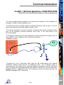
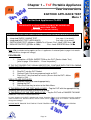
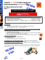
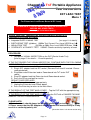
Australian made to
comply with the
requirements of the
Standard AS/NZS 3760
Ph: (08) 8331 8892
Int: (+61) 8 8331 8892
Email: [email protected]
www.wavecom.com.au
REVISION 1.11 February 2005
Ph: (07) 3274 2466
Int: (+61) 7 3274 2466
Email: [email protected]
www.nesco.com.au
Accessories Supplied
(With the Range of TnT Portable Appliance Testers)
•
•
•
•
•
Portable Appliance Tester Instruction Manual
Manufacturers Calibration Certificate
IEC Lead
Earth Lead with Alligator Clip
Soft Carry Case
Manufacturers Recommendations
(For the Range of TnT Portable Appliance Testers)
Calibration:
The manufacturer recommends a routine calibration verification of readings
for determining the accuracy of readings on a 12 Monthly basis.
Page 2
Index
Accessories Supplied
Manufacturers Reccomendations
Index
2
2
3
Safety Warning
The TnT Portable Appliance Tester (Diagram)
Competent Person
Disclaimer & Limited Warranty
4
5
6
6
IMPORTANT INFORMATION:
TECHNICAL INFORMATION:
Class 1 (Earthed Appliance) Construction
Class 2 (D/Insulated) Construction
Testing of Electrical Equipment
To Change Test Voltage (250/500VDC Select)
INTEGRATED TESTS:
7
8
9-10
10
SUPPLY MAINS TEST
NCNT TEST
11
12
VISUAL INSPECTION TEST
13
CHAPTER 1 – TnT Portable Appliance Tester Instructions:
TnT Test Function Flow Chart
EARTHED APPLIANCE TEST
DOUBLE INSULATION TEST
EXT LEAD TEST
14
15
16
17
CHAPTER 2 - TnT-el Portable Appliance Tester Instructions:
TnT-el Test Function Flow Chart
TESTS Common to ALL MODELS
LEAKAGE TEST
18
19
20-21
CHAPTER 3 – TnT+ Portable Appliance Tester Instructions:
TnT+ Test Function Flow Chart
TESTS Common to ALL MODELS
POWER TEST
RCD TEST
22
23
24-25
26-30
Specifications for the TnT, Tnt-el & TnT+
31
Optional Accessories
32
Other Relevant Authorities
33
FIRST TEST:
[Please note: Specific PAT Tests are noted in blue text]
Page 3
Safety Warning
!
When using any electrical appliance SAFETY must always be observed.
Testing appliances is no exception and in fact MORE care must be
taken to ensure personal safety is met.
Although the TnT range of products has been designed to meet
stringent requirements, no person can be completely protected against
the consequences of the incorrect use of an electrical device.
We advise that appliance testing should be conducted by a competent
and suitably trained person.
For maximum safety, always ensure that the following advice is
followed;
•
•
•
•
•
•
The equipment being tested is in good repair.
All user instructions are followed.
Double check power supply connections (LEDs).
Always use specified fuses and protection devices.
Do not use leads that require repair or are damaged.
If you are unsure, call a Licensed Engineer/Electrician.
Page 4
The TnT Portable Appliance Tester
(Diagram)
Display
Test Function F1
These buttons are NOT
IN USE & are reserved
for future functions
Test Function F2
Test Function F3
Return/Enter Button
Supply
Indicator Lights
Power Lead
IEC Socket
Fuse
Device Under Test (DUT) Socket
[Diagram shown is a sample only and may not be exact to each specific model of TnT Appliance Tester]
Page 5
Competent Person
!
To ensure that all electrical equipment or devices that are used to perform specific tasks,
are inspected and tested and tagged correctly, regulations require that a competent
person such as a Licensed Electrician be employed to perform the required tests.
A person competent to undertake Inspection and Testing of electrical equipment must
therefore have:
1.
2.
3.
4.
5.
Knowledge and practical experience of electricity and its hazards.
A clear understanding of precautions to avoid danger.
The ability to recognise, at all times, whether it is safe for work to continue or not.
The ability to carry out visual examinations of electrical equipment.
The ability to distinguish between electrical equipment that is double insulated and
equipment that is earthed as well as being able to identify the appropriate test for
each type.
6. The competency to carry out the Earthing Continuity, Insulation Resistance or
Leakage Test and RCD tests on electrical equipment safely.
7. The knowledge of how to use the relevant testing instruments, interpret and record
the results for compliance with the Standard/Workplace requirements.
8. The knowledge to be able to correctly recommend the frequency of testing
required.
Due to the potential hazards of electrical testing all care must be taken.
Disclaimer
LIMITED Warranty
The Manufacturer warrants its products against defects in materials and workmanship for a
period of 12 months from the date of purchase. During the warranty period, the manufacturer
will repair (or at its option replace at no charge) the product that proves to be defective. This
warranty does not apply if the product has been damaged by accident, abuse, misuse or missapplication or as a result of service or modification by anyone other than Electromate TnT.
Electromate TnT product range of devices or its’ manufacturer IS NOT RESPONSIBLE FOR
INCIDENTAL OR CONSEQUENTIAL DAMAGES RESULTING FROM THE BREACH OF
ANY EXPRESS OR IMPLIED WARRANTY, INCLUDING DAMAGE TO PROPERTY AND TO
THE EXTENT PERMITTED BY LAW, DAMAGES FOR PERSONAL INJURY. The Distributors
of this product cannot assume liability or responsibility for any loss or damage resulting from
the use of this device.
Electromate TnT manufacturer reserves the right to discontinue models, change specification,
price or design, at any time without notice or obligation.
Page 6
Technical Information
CLASS 1 (Earthed Appliance) CONSTRUCTION
(Single basic insulated and protectively earthed equipment)
This type of product design provides two safety barriers between all live conductors at
dangerous voltages and the equipment user.
The provision of basic insulation between exposed metal parts and live parts is the first
barrier to provide basic protection against electric shock.
The second safety barrier is by the connection of exposed (accessible) conductive (metal)
parts to the protective earthing conductor (earth wire) in the fixed wiring of the
device/Installation.
The protective earthing terminal of the equipment must be marked with the word "earth" or
the symbol "E" or the symbol for Earth Terminal or Protective
Conductor Terminal.
1
To perform this test a continuous earth loop must be made between the exposed
conductive material (metal) and the TnT appliance tester. This is done by means of
connecting the earth lead with the crocodile clip/probe attached to a GOOD earth point
(paint & coatings will not provide effective connections) and the DUT (Device Under Test)
plugged into the TnT appliance testers’ DUT socket. [as shown in the above picture]. The
Maximum allowable limit is 1.0Ω (ohm).
Page 7
Technical Information
Continued
CLASS 2 (Double Insulated) CONSTRUCTION
(Double insulated equipment)
This method of construction employs two safety barriers comprising two layers of
insulation between dangerous voltages and the user of the equipment.
The first layer of insulation is formed around the live conductor and is termed ‘the
Functional Insulation’.
The second layer of insulation is termed ‘the Supplementary Insulation’. In Class II
equipment, protection against electric shock does not rely on
basic insulation only, but has additional supplementary
insulation such as double insulation or reinforced insulation
provided, there being no reliance on precautions in the fixed
wiring of installation.
Class II equipment is marked with the words "DOUBLE
INSULATION" or the symbol
For double insulated under Safety Symbols:
Note 1 – Double Insulation is insulation comprising both basic and supplementary
insulation.
Note 2 – Reinforced Insulation is a single insulation system with a degree of protection
against electric shock, which is equivalent to double insulation.
Page 8
1M
Technical Information
Continued
Testing of Electrical Equipment
Many testing personnel have some reservations in testing sensitive, electronic equipment
using a 500V DC insulation test. There is a perceived fear of causing internal damage
from over voltage. With the introduction on the TnT Range of appliance testers, these
concerns are alleviated.
The TnT Range of electrical portable appliance testers are safe to test electronic
equipment as the tests are carried from Active-Neutral (shorted by a relay inside the
tester) to Earth. No dangerous voltages pass through in this mode to the internal
components of the DUT (Device Under Test). If these tests are done using an Insulation
Tester only and the user tests Active to Neutral, this would be a cause of potential
damage, this is why the TnT product range is far safer to use.
Some changes may be required in certain configurations where fitted surge protection
devices (MOV'
s) in the DUT may cause a failed test result. Applying 500V in this these
situations can cause the surge protection devices to trip, therefore conducting the applied
voltage to earth, thus showing a failure of insulation. In these instances the test voltage
should be changed to 250V then retest. If DUT still fails, check with the DUT Operators
Manual or an electrician. [Refer to page 13 for details - ‘Double Insulation Test’
250/500VDC to change test voltage].
Under these circumstances, it would be difficult for any damage to occur to either the
surge protection device or the DUT, as there is insufficient current generated by the TnT-el
appliance tester.
Leakage Test:
If there are any doubts with insulation testing of the equipment, the standard
(AS/NZ3760 since 2001) allows for an alternative test method. A Leakage Test can be
performed instead. (The TnT-el & TnT+ models are designed to perform these tests).
NOTE: 10Amps MAXIMUM Resistive Load only (Standard TnT-el & TnT+ units).
A Leakage Test applies power to the Device Under Test (DUT) and measures the
imbalance of leakage current from the DUT between the active and neutral conductors.
The leakage is tested to the limits specified in the standard and a Pass/Fail result as well
as a digital reading is provided to ensure that the user gains as much information as
necessary.
Earth Continuity Test:
The TnT-el conducts earth continuity tests at Approx 200mA. Continuity tests at
higher currents are not required and are not recommended on certain
equipment as this can cause severe damage or premature failure to the DUT (as per
AS/NZ3760).
Page 9
Technical Information
Continued
Testing of Electrical Equipment
3 Phase Testing:
3 Phase appliances can be tested by the TnT, TnT-el, TnT+ or the TnT-3PL appliance
tester. This test is carried out by using the adaptor connection sockets. As the insulation
tests are from Phase to Earth, only a 500V insulation test is required. These adaptors can
be made by your electrician or purchased as an accessory. [See ‘Optional Accessories’ on
page 18 for details - when ordering please state plug configuration of 3 phase plug. E.G.
5 pin Clipsal 56 series 20A].
CAUTION: Ensure that these adaptors are used only for appliance testing.
To Change Test Voltage
(250/500 VDC Select - To Change the Insulation Test Voltage on all models)
Procedure:
Step 1:
Step 2:
Step 3:
Hold down the Return/Enter Key
Press the F2 Key
(F2 function – Note screen flashes)
For 250v – Press the F3 Key
For 500v – Press the Return/Enter Key
Finish:
The display will confirm the change and return to the
Main Menu automatically. The desired voltage has
now been selected.
TO CHANGE VOLTAGE BACK, REFER TO STEP 1.
Please Note:
1. In earlier models the Return/Enter Key may need to be pressed 3 times to change
Voltages.
2. The TnT will automatically default to 500v when restarted.
Page 10
Integrated Tests
Information
SUPPLY MAINS TEST
The Supply Mains TEST checks the Polarity & Connectivity of the mains
supply by LED’s (see below). This test is also a part of all of the testing
functions of this unit.
A-N, A-E
N-E
If the N-E (red) light is on and you need to conduct load/leakage tests
DO NOT CONTINUE. If you are carrying out standard Insulation and
Earth Bond tests, it is generally safe to continue.
This light will glow if a voltage difference lies between the neutral and
the earth, or if no earth is connected to the TnT-el supply. (If working
with a generator or inverter, this is most likely to occur and you may
need to consult an electrician before proceeding).
A-E
If both the A-E & A-N (green) lights are on but not the N-E (red);
Mains Supply is OK.
Continue to Test.
A-N
N-E
A-E
If both of the N-E (red) & A-E (green) lights are on,
Consult an Electrician, as there is a fault with the Mains Supply.
A-N
Page 11
Integrated Tests
Information
NCNT TEST
(No Connection No Test)
The TnT appliance tester ensures that the Device Under Test (DUT) is
plugged in and switched on. This test is also a part of all of the testing
functions of this unit.
This test function ensures that the Device Under Test (DUT) is plugged into the TnT
appliance tester and that it is switched on.
If the DUT is not plugged in and the TnT appliance tester detects that no DUT is present,
plug in the DUT to continue the test. Confirm or ‘QUIT’ to return to the main menu.
If for some reason the NCNT circuit does not detect the DUT but it is actually plugged in
and turned on, the operator will need to override the TnT appliance tester to continue the
test.
To do this - press the F3 Key.
With an emphasis in the standard AS/NZ3760 for carrying out the live testing the TnT
appliance tester will indicate for you to check if the DUT is plugged in and switched on. If
the DUT is not plugged in and/or recognised, it may require a live test therefore making it
necessary for the operator to carry out a full functional Leakage Test (TnT-el & TnT+
appliance tester models only).
This function is to ensure that correct testing procedures are carried out in accordance
with the Standard AS/NZ3760.
TO NOTE:
i.
When using 3-Phase adaptors the NCNT function will need to be over ridden by
pressing the ‘OK’ key prior to the TnT appliance tester performing the assigned
test.
Some single Phase appliances controlled by contactors will require manual over
ride also. In some instances holding the ‘ON’ button of the DUT will enable the
NCNT function to work normally.
Page 12
Visual Inspection (FIRST TEST)
Information
THIS TEST IS TO OCCUR BEFORE ANY OTHER TEST
IS CARRIED OUT USING ANY OF THE RANGE OF
TnT APPLIANCE TESTERS.
In regard to the Device Under Test (DUT), please ensure that;
1. There is no damage or component defect to the accessories, plugs, outlet sockets
or connectors (physical).
2. There are no cracks &/or abrasions.
3. There are no exposed inner cores or conductors (flexible) and that the supply cords
are not twisted or distorted.
4. Any Fuse / Over load protection components (if fitted) are checked.
5. All labels, markings and warning indicators (of the maximum load to be connected
to the device) are legible and intact.
6. The insulation is not damaged in any way i.e. melted, cuts or abrasions. There are
no iron filings in the insulation. There is no insulation tape on the lead.
7. Any flexible cords and/or leads are effectively anchored (glands and grommets
intact).
8. All covers/guard are in place and secure as intended by the supplier/manufacturer.
9. All safety devices and systems are in good working order. (ie. overload latches &
buttons).
10. No dust &/or dirt obstructs any exhausts or ventilation outlets.
11. All controls are working properly and are secure and aligned.
Important:
IF RESULT IS A FAIL
If a Device Under Test (DUT) fails any of the above, it should be deemed to have
FAILED the Visual Test, and therefore no other tests need be performed. If this is
the case the DUT should be tagged with a danger tag and removed from service.
It is recommended by the manufacturer and distributor of this product that if a
DUT has failed a test it SHOULD NOT BE RETURNED TO SERVICE. To do so
would be considered unsafe.
Page 13
Chapter 1 – TnT Portable Appliance
Part No: WCM-TNT
Test Instructions
TnT Test Function Flow Chart
Main Menu 1
F1 Earth Test
F2 D/Ins Test
F 3Ext Lead Test
F1 Earth Test
Supply Mains Test
NCNT Test
Earth Bond Test
Insulation Test
Results Summary
F2 D/Ins Test
Supply Mains Test
NCNT Test
Double Ins Test
Results Summary
F3 Ext Lead Test
Supply Mains Test
Earth Bond Test
Insulation Test
Continuity & Polarity
Test
Results Summary
Page 14
Please note: Menu 1 is
common to all models
[TnT, TnT-el & TnT+]
Chapter 1 – TnT Portable Appliance
Test Instructions
EARTHED APPLIANCE TEST
Menu 1
For Earthed Appliances CLASS 1
PLEASE NOTE: A VISUAL INSPECTION MUST BE CARRIED OUT
BEFORE ANY OTHER TESTS.
[refer to page 13 for more details]
The EARTHED APPLIANCE TEST completes the following sequence as part of its testing procedure:
1. Integrated SUPPLY MAINS TEST
[see page 11 for details]
2. Integrated NCNT TEST (APPLIANCE)
[see page 12 for details]
3. EARTH BOND TEST (@200ma) :200Ma Test Current. Pass Level LESS than 1 Ω
4. INSULATION TEST (@ 250v or 500v)
:Pass Level GREATER than 1M Ω
Note: 250v insulation testing applies to Class 1 appliances if selected [refer to page 10 for details 250/500VDC to change test voltage].
PROCEDURE:
1.
Complete a VISUAL INSPECTION on the DUT (Device Under Test)
[refer to page 13 for details – ‘Visual Inspection’].
IF THE DUT PASSED THE ‘VISUAL INSPECTION’, CONTINUE WITH THE FOLLOWING
INSTRUCTIONS [if not, refer to page 13 ’IF RESULT IS A FAIL’ ]:
2.
3.
4.
Plug DUT into the DUT Socket.
Connect Earth Clip to any exposed metal on DUT.
Press the F1 key and wait for results (Ensure that the DUT’s Mains
switch is ON).
RESULTS ARE DISPLAYED
5.
Read the result and record appropriately.
6.
Unplug the DUT.
7.
Press the Enter key to return to the Main Menu.
IF THE RESULT OF THE TEST WAS A ‘PASS’ - Tag the DUT with the appropriate tag,
including ‘Next test Due’ date and return to service.
IF THE RESULT OF THE TEST WAS A ‘FAIL’ - Tag the DUT with a DANGER TAG AND
REMOVE THE DUT FROM SERVICE.
In some situations if the DUT is labelled with “Surge Protection Fitted” or if it is electronic and fails, conduct a
250V-insulation test. Should it still fail, remove it from service. [refer to page 10 for details - 250/500VDC to
change test voltage]
PLEASE NOTE: ENSURE THAT THE DUT TO BE TESTED IS ISOLATED FROM ANY POTENTIAL
GROUND LOOP.
Page 15
Chapter 1 – TnT Portable Appliance
Test Instructions
DOUBLE INSULATION TEST
Menu 1
For Double Insulated Appliances CLASS 2
PLEASE NOTE: A VISUAL INSPECTION MUST BE CARRIED OUT
BEFORE ANY OTHER TESTS.
[refer to page 13 for more details]
The DOUBLE INSULATION TEST completes the following sequence as part of its testing procedure:
1. Integrated SUPPLY MAINS TEST
[see page 11 for details]
2. Integrated NCNT TEST (APPLIANCE)
[see page 12 for details]
3. DOUBLE INSULATION TEST
(@ 250v or 500v) Pass Level GREATER than 1 M Ω
PROCEDURE:
1. Complete a VISUAL INSPECTION on the DUT (Device Under Test)
[refer to page 13 for details – ‘Visual Inspection’].
IF THE DUT PASSED THE ‘VISUAL INSPECTION’, CONTINUE WITH THE FOLLOWING
INSTRUCTIONS [if not, refer to page 13 ’IF RESULT IS A FAIL’]:
2. Plug DUT into the DUT Socket.
3. Connect Earth clip to any exposed metal on DUT (if any, or device can be wrapped
in foil or use metal mesh braid [Part No: TnT-ES 500]
4. Press the F2 key and wait for results (Ensure that the DUT’s Mains switch is ON).
RESULTS ARE DISPLAYED
5. Read the result and record appropriately.
6. Unplug the DUT.
7. Press the Enter key to return to the Main Menu.
IF THE RESULT OF THE TEST WAS A ‘PASS’ - Tag the DUT with the appropriate
tag, including ‘Next test Due’ date and return to service.
IF THE RESULT OF THE TEST WAS A ‘FAIL’ - Tag the DUT with a DANGER TAG AND
REMOVE THE DUT FROM SERVICE.
In some situations if the DUT is labelled with “Surge Protection Fitted” or if it is electronic and fails, conduct a
250V-insulation test. Should it still fail, remove it from service. [refer to page 10 for details - 250/500VDC to
change test voltage]
Page 16
Chapter 1 – TnT Portable Appliance
Test Instructions
EXT LEAD TEST
Menu 1
For Extensions Lead/Power Board & IEC Leads
PLEASE NOTE: A VISUAL INSPECTION MUST BE CARRIED OUT
BEFORE ANY OTHER TESTS.
[refer to page 13 for more details]
The Ext. Lead TEST completes the following sequence as part of its
comprehensive testing procedure:
[see page 11 for details]
1. Integrated SUPPLY MAINS TEST
2. EARTH BOND TEST (@200ma) :200Ma Test Current. Pass Level LESS than 1 Ω
3. INSULATION TEST
(@ 250v or 500v) Pass Level GREATER than 1M Ω
4. CONTINUITY & POLARITY TEST 250VAC Checks continuity & polarity of leads
PROCEDURE:
1. Complete a VISUAL INSPECTION on the DUT (Device Under Test)
[refer to page 13 for details – ‘Visual Inspection’].
IF THE DUT PASSED THE ‘VISUAL INSPECTION’, CONTINUE WITH THE FOLLOWING
INSTRUCTIONS [if not, refer to page 13 ’IF RESULT IS A FAIL’ ]:
2. Plug in IEC adaptor lead into IEC socket ( Remove Earth lead if inserted - Please
read note below)
3. Plug Male end of Extension lead or Power board into TnT tester DUT
socket
4. Plug IEC adaptor lead into Extension lead /Power board socket.
5. Press the F3 key and wait for results.
RESULTS ARE DISPLAYED
6. Read the result and record appropriately.
7. Unplug the Extension lead /Power board.
8. Press the Enter key to return to the Main Menu.
IF THE RESULT OF THE TEST WAS A ‘PASS’ - Tag the DUT with the appropriate tag,
including ‘Next test Due’ date and return to service.
IF THE RESULT OF THE TEST WAS A ‘FAIL’ - Tag the DUT with a DANGER TAG AND
REMOVE THE DUT FROM SERVICE.
PLEASE NOTE:
1. Extension leads should always be uncoiled before using or testing.
2. Please ensure that the IEC Adaptor & the IEC socket are inserted firmly or it may
result in a continuity/polarity fail.
[Illustration above is for demonstration only]
Page 17
Chapter 2 - TnT-el Portable Appliance
Part No: WCM-TNT-EL
Test Instructions
TnT-el Test Function Flow Chart
Please note: Menu 1 is
common to all models
[TnT, TnT-el & TnT+]
Main Menu 1
Menu 2
F1 Earth Test
F2 D/Ins Test
F 3Ext Lead Test
F1Earthed Leakage Test
F2 D/Ins Leakage Test
F3 RCD Appliance
Leakage Test
F1 Earth Test
F1 Earthed Leakage Test
Mains Supply Test
NCNT Test
Earth Bond Test
Insulation Test
Results Summary
Mains Supply Test
NCNT Test
Earth Bond Test
Earth Leakage (5mA)
Results Summary
F2 D/Ins Test
D/Ins Leakage Test
Mains Supply Test
NCNT Test
Double Ins Test
Results Summary
Mains Supply Test
NCNT Test
Earth Leakage (1mA)
Results Summary
F3 Ext Lead Test
RCD Appliance Leakage Test
Mains Supply Test
Earth Bond Test
Insulation Test
Continuity & Polarity
Test
Results Summary
Mains Supply Test
NCNT Test
Earth Bond Test
Earth Leakage (2.5mA)
Results Summary
Page 18
Chapter 2 - TnT-el Portable Appliance
Test Instructions
TESTS COMMON TO ALL MODELS
Menu 1
EARTHED APPLIANCE TEST
[refer pg 15]
DOUBLE INSULATION TEST
[refer pg 16]
EXT LEAD TEST
[refer pg 17]
Please note: Menu 1 is
common to all models
[TnT, TnT-el & TnT+]
Page 19
Chapter 2 - TnT-el Portable Appliance
Test Instructions
LEAKAGE TEST
Menu 2
The Leakage Test is an alternate method to performing insulation resistance
tests. Leakage testing is a major function of the TnT-el & Tnt+ models
PLEASE NOTE: A VISUAL INSPECTION MUST BE CARRIED OUT
BEFORE ANY OTHER TESTS.
[refer to page 13 for more details]
This test determines errors of leakage not otherwise detected in a normal insulation test.
If there are any doubts with insulation testing of the equipment, the Standard (AS/NZS
3760 since 2001) allows for a leakage test to be carried out instead. The TnT-el & TnT+
appliance testers have been designed to perform these tests. The Leakage Test applies
power to the Device Under Test (DUT) and measures any imbalance or leakage current.
The leakage is tested to the limits of the class types specified in the Standard AS/NZS
3760 ie. Class 1 = > 5mA as Fail.
The Limit of imbalance measured on the TnT-el appliance tester will read well in excess of
the limits set in mA. However, should the supply circuit be protected by an RCD this
device will trip any where between 10 to 30mA and trip the mains supply switch OFF.
PROCEDURE:
1. Complete a VISUAL INSPECTION on the DUT (Device Under Test)
[refer to page 13 for details – ‘Visual Inspection’].
IF THE DUT PASSED THE ‘VISUAL INSPECTION’, CONTINUE WITH THE FOLLOWING
INSTRUCTIONS [if not, refer to page 13 ’IF RESULT IS A FAIL’]:
2. Press Return Key to view Menu 2.
3. Press a Function Key (as follows) to start the test/s. Press F1, F2 or F3 (depending
on the type of DUT you are testing).
1. F1 Earth Leakage
Limit set to MAXIMUM then 5mA Fail
2. F2 D. Insulated Leakage & Ext leads
Limit set to MAXIMUM than 2.5mA Fail
3. F3 RCD Leakage
CONFIRM SAFE TO CONTINUE? OK/QUIT. IF OK, DEVICE WILL TURN ON.
ENSURE SAFE OPERATION!
RESULTS ARE DISPLAYED
4. Read the result and record appropriately.
5. Unplug the DUT
6. Press the Enter key until you return to the Main Menu.
!
IF THE RESULT OF THE TEST WAS A ‘PASS’ - Tag the DUT with the appropriate tag,
including ‘Next Test Due’ date and return to service.
IF THE RESULT OF THE TEST WAS A ‘FAIL’ - Tag the DUT with a DANGER TAG AND
REMOVE THE DUT FROM SERVICE.
Note: Test will PASS even if DUT is not plugged in.
Page 20
Chapter 2 - TnT-el Portable Appliance
Test Instructions
[continued] LEAKAGE
TEST
Menu 2
More Information – Leakage Test
The Leakage Test allows the user to operate the DUT in normal operation conditions and
measure its Operating Leakage current. The displayed parameter is mA:
A predefined value for individual class types is programmed into your TnT-el & TnT+
appliance testers. These limits are set according to the AS/NZ3760. Should these values
change in future it can be simply altered in firmware. A Pass / Fail will also be displayed
at the end of the test.
The run time period can be adjusted (by 5sec increments) with the use of WinPATS Lite
program V2.0 and above. The factory default setting is 20sec. Once reprogrammed using
WinPATS Lite the TnT-el appliance tester can run independently with its new set run time.
The mA Display Range 0.0 to 22.0 mA.
Before operating ensure the equipment is firmly secured to eliminate the possibility
of causing injury or damage. This function turns the DUT on; any rotating devices
have clearance from body or object. Appliances may jump off benches or cause
serious damage if not secured properly.
To Stop Operation Press the Return /Enter key
at any time.
The unit will power down after 20 seconds as factory default.
!
CAUTION: This test turns the Device Under Test (DUT) ON.
10 Amp (Resistive) Load MAX. The TnT-el appliance tester
monitors for potential loads over 10 Amps and displays
accordingly.
Page 21
Chapter 3 – TnT+ Portable Appliance
Part No: WCM-TNT+
Test Instructions
TnT+ Test Function Flow Chart
Please note: Menu 1 is common to all models [TnT, TnT-el & TnT+]
(refer page 14 for more details)
+
Menu 2
F1 Power Test
F2 Leakage Test
F3 RCD Test
Menu 2
F1 POWER TEST
Instructions for POWER TEST:
F1 + F3 = POWER RESULTS
Menu 2
F2 LEAKAGE TEST
APPLIANCE POWER TEST
Continue if Safe?
OK
240 V
0.000 A
0.00 PF
QUIT
LEAKAGE TEST
EARTH LEAKAGE TEST
(F1) Earthed
Devices
Continue if Safe?
LEAKAGE TEST
EARTH LEAKAGE TEST
OK
(F2) D.Ins., Ex-Lead
Instructions for LEAKAGE TEST for;
(F2) D.Ins., ExLead
OK
LEAKAGE TEST
Menu 2
RCD TEST
QUIT
EARTH LEAKAGE TEST
Continue if Safe?
(F1) Earthed Devices
(F2) D.Ins., Ex-Lead
(F3) RCD
Protected
QUIT
Continue if Safe?
(F1) Earthed Devices
• Earthed Devices: F2 + F1 + F3 = RESULTS
• D.Ins., Ex-Lead: F2 + F2 + F3 = RESULTS
• RCD Protected: F2 + F3 + F3 = RESULTS
POWER RESULTS
OK
QUIT
0W
0 VA
To return to MENU 2
Press RETURN
LEAKAGE RESULTS
PASS < 5.0 mA
0.0
mA
Pass
ESC
LEAKAGE RESULTS
PASS < 1.0 mA
0.2mA
Pass
ESC
EMERGENCY STOP
ABORT
To return to MENU 2
Press RETURN
LEAKAGE RESULTS
PASS < 2.5 mA
1.0mA
Pass
ESC
&
TIMED TEST
RCD TESTS
(F1) Time Test
(F2) Ramp Test
30mA
• (F1) 0’ phase
• (F2) 180’ phase
• (F3) Change Current
RCD MULTIPLYER
• (F1) Up
• (F2) Down
• (F3) START
1.0
RCD TIMED TEST
Time:
4ms
Instructions for RCD TEST for;
Time Test
O’ Phase - F3 + F1 + F1 + F3 = RESULTS
18O’ Phase - F3 + F1 + F2 + F3 = RESULTS
Change Current F3 + F1 + F3 + F3 = SETTING
Ramp Test
TIMED TEST
30mA
• (F1) 0’ phase
• (F2) 180’ phase
• (F3) Change Current
RCD TEST CURRENT
RCD TEST CURRENT
• (F1) Up
• (F2) Down
• (F3) SET
• Up
30mA
• Down
• SAVING SETTINGS
30mA
F3 + F2 + F3 = RESULTS
RCD RAMP TEST
RCD TESTS
(F1) Time Test
(F2) Ramp Test
Page 22
•
(F3) START
RCD RAMP TEST
TESTING
RCD RAMP TEST
Time:
4ms
Chapter 3 – TnT+ Portable Appliance
Test Instructions
TESTS COMMON TO ALL MODELS
Menu 1
EARTHED APPLIANCE TEST
[refer pg 15]
DOUBLE INSULATION TEST
[refer pg 16]
EXT LEAD TEST
[refer pg 17]
Please note: Menu 1 is
common to all models
[TnT, TnT-el & TnT+]
Page 23
Chapter 3 – TnT+ Portable Appliance
Test Instructions
POWER TEST
Menu 2
The Power Test is for the purposes of monitoring and performance
testing the DUT up to the current value 10Amps (resistive load)
PLEASE NOTE: A VISUAL INSPECTION MUST BE CARRIED OUT
BEFORE ANY OTHER TESTS.
[refer to page 13 for more details]
The Power TEST completes the following sequence as part of its comprehensive
testing procedure:
1. Integrated SUPPLY MAINS TEST
2. POWER TEST
[see page 11 for details]
PROCEDURE:
1. Complete a VISUAL INSPECTION on the DUT (Device Under Test)
[refer to page 13 for details – ‘Visual Inspection’].
IF THE DUT PASSED THE ‘VISUAL INSPECTION’, CONTINUE WITH THE FOLLOWING
INSTRUCTIONS [if not, refer to page 13 ‘IF RESULT IS A FAIL’]:
2. Plug in IEC adaptor lead into DUT socket ( Remove Earth lead if inserted - Please
read note below)
3. Plug Male end of DUT into DUT socket
4. Press the F1 key
RESULTS ARE DISPLAYED
5. Read the result and record appropriately.
6. Unplug the Extension lead /Power board.
7. Press the Enter key to return to the Main Menu.
IF THE RESULT OF THE TEST WAS A ‘PASS’ - Tag the DUT with the appropriate tag,
including ‘Next test Due’ date and return to service.
IF THE RESULT OF THE TEST WAS A ‘FAIL’ - Tag the DUT with a DANGER TAG AND
REMOVE THE DUT FROM SERVICE.
[Illustration above is for demonstration only]
Page 24
Chapter 3 – TnT+ Portable Appliance
Test Instructions
[continued] POWER
TEST
Menu 2
More Information re Power Test
This test is Ideal for service agents and electricians. The User can plug in the appliance and turn it
on with real time measurements displayed on the display. This is useful when testing a DUT with
a compliance/name plate on it. The operator can compare the name plate details of operating
voltage, operating current, and power factor etc. should the appliance exceed the said values on
the name plate it could be deemed faulty and require service.
To select the second menu, press and release the RETURN/ENTER
Button.
This Menu will display 3 functions:
Power Test
Leakage Test
RCD Test
The Power Test allows the user to turn the appliance on and measure its performance as
a digital wattmeter. Displayed parameters are:
Volts AC
Current
Volt Amps
Power factor
Watts
Before operating, Ensure the equipment firmly secured and is free from any
possibility of causing injury or damage. This function turns the appliance on any,
rotating devices have clearance from body or object. Appliances will jump of
benches if not secured properly.
!
!
CAUTION this test turns on the appliance under test. 10 Amp
(Resistive) Load MAX.
To begin the operation Press and Hold F1 key for 2 seconds to start
test.
To Stop operation Press Return /Abort key at any
time.
The unit will power down after 20 seconds as default
If 10A HBC fuse is blown appliance will not operate in Power test or Leakage test modes. Replace
fuse only with M20 10A HBC fuses. Any other fuse voids warranty and manufacturers design. Do
not open TnT case as there are no serviceable parts inside.
LEAKAGE TEST
[refer pg 20-21]
Page 25
Chapter 3 – TnT+ Portable Appliance
Test Instructions
RCD TEST
Menu 2
NOTE: Where ANY RCD testing, is to be carried out any circuit that is protected by
an RCD in the main switchboard (upstream), it’s most likely to trip this upstream RCD.
When performing RCD trip time or trip current tests on any down stream (portable) RCD
devices, the RCD in the switchboard will trip faster. This is due to increased upstream
levels of leakage current from the additional circuits and devices connected to it. The fixed
RCD’s can also have better connectivity, sensitivity and mechanical mechanisms.
To avoid tripping large areas in the work place monitored by the switchboard RCD it is
suggested that an RCD isolation transformer be used. (TnT-ISOT) These are designed
specifically for the purposes of field RCD tripping.
DO NOT use these Transformers for any other purpose.
Ratings 240v in 240v Out @ 30VA Fuse protected Primary winding 500ma
To perform RCD tests the TnT+ supply lead needs to be plugged in to the RCD device to
be trip tested. For tripping switchboard mounted (Fixed) RCDs Plug TnT+ into GPO
marked RCD protected or if known to be protected circuit. (Diagram 2)
If testing portable RCD devices on power boards or extension leads plug TnT+ into power
board or lead (recommend Isolation transformer) Diagram 1
Portable
RCD
TnT+
Isolation
Transformer
Wall
GPO
May be
RCD
protected
TnT+ Plug
Xlead
Socket
DIAGRAM 1
Page 26
Chapter 3 – TnT+ Portable Appliance
Test Instructions
[continued]
RCD TEST
Menu 2
SWITCH BOARD
FIXED RCD
ON
TnT+
TnT+ Plug
Wall
GPO
OFF
DIAGRAM 2
To select the second menu, press and release the RETURN/ENTER
Button.
This Menu will display 3 functions:
Power Test
Leakage Test
RCD Test
To enter RCD menu press and release F3 button
RCD sub-menu: This will display a further 2 options
!
F1 – RCD Trip Time
F2 – RCD Trip Current
CAUTION Pressing F2 at this point will cause tripping if RCD fitted.
To exit this menu, press and release the Return button
Page 27
Chapter 3 – TnT+ Portable Appliance
Test Instructions
RCD TEST [continued]
Menu 2
1. RCD Trip Time.
Press F1 for this option and the following
menu appears.
Trip Time Testing: This principal is designed to
trip RCD devices at a fixed current and to
determine the trip time of the RCD device.
This function is factory set to 30mA for fast testing
the user can set the current to X0.5, X1.0, X 5 using the RCD Multiplier.
I.E. 30mA X 0.5 =15mA
30mA X 1.0 = 30mA
30mA X 5.0 = 150mA
(this also is effective on any set test current of the
RCD tester from 5mA to max 500mA output.)
These tests should result in no-trip, trip & fast trip times respectively.
F1 - 0 deg
F2 - 180 deg
This is the positive half of the mains supply cycle. (50HZ
Aust/NZ).
Press F1 – The preset mA test current will then be used
in the following test and begin the trip test from the
positive half of the sine wave
This is the negative half of the mains supply cycle. (50HZ
Aust/NZ).
Press F2 – The Preset mA test current will then be used
in the following test and begin the trip test in negative half
of the sine wave.
Change Test mA
F3 – Change test mA
500mA
This allows the user to set the trip current level. 5mA to
To exit menu, press and release the Return button.
Page 28
Chapter 3 – TnT+ Portable Appliance
Test Instructions
[continued]
RCD TEST
Menu 2
The TnT+ displays and maintains the last, set trip current value.
If the user wishes to change the value of the trip current the following steps enable the
changes.
Press and release F3 to display test
current.
Up - This button raises the trip current in
1mA increments to 500mA. Hold the
button and the value will scroll faster the
longer depressed. Once 500mA limit is
reached the value will then loop over and
start again from 0mA.
Down - This button decreases the trip current in 5mA increments. Hold the button
and the value will scroll faster the longer depressed. Once 0mA limit is reached the
value will then loop over and start again from 500mA.
Set - This button sets the selected current for the next trip time test. The TnT+ will
then return to the current trip time test screen.
The displayed trip time is in milliseconds. This is the time taken for the RCD device to trip
once the injected fault current has been applied. The TnT+ injects a true fault current
value using a real time compensation calculation of the actual voltage at the time of test.
Hence delivering a true and accurate trip current no compensation of voltage fluctuations
corrections required.
Voltage range 210 – 270V ac.
As stated above this screen sets the multiplier of
the set test current. Use the F1 or F2 keys to scroll
through
the multipliers X0.5, X1.0, X5.0 of the set current.
Maximum output current = 500mA..
I.E if set test current were 100mA then 100 X 5.0 =500mA.
If set test current = 200mA then maximum out put 5 x 200ma =1A is out of range. Unit will
not deliver this output current and display on Screen “OUT of RANGE”.
Page 29
Chapter 3 – TnT+ Portable Appliance
Test Instructions
RCD TEST [continued]
Menu 2
Press F3 to START test.
TnT+ display will display result for 20 seconds after mains supply is tripped.
!
CAUTION Pressing F3 at this point will cause tripping if RCD fitted to
circuit.
TRIP CURRENT TEST. This testing principal is designed to trip RCD devices using a
ramping up current value, to determine the trip current of the RCD device. This useful test
allows the user to determine circuit leakage load/pre-loading of RCD circuit. This can
assist in determining nuisance tripping issues or determining RCD performance if
suspected faulty or inconsistent in performance. The TnT+ has a nominal leakage current
of 2mA, which should be added to the result of test.
E.g. if RCD tripped at 22mA + 2mA (TnT+) =24mA trip current.
RCD Trip Current. Press F2 for this option.
!
CAUTION Pressing F2 at this point will cause tripping if RCD
fitted to circuit.
The Trip Current Test will ramp the mA current up until the RCD breaker trips. Current
range 2.55 - 500mA. This test can go for up to 10 sec to scroll through full range if RCD
faulty or not fitted.
Repeated testing in this mode will cause heating of TnT+. Should over heating occur the
internal temperature sensor will cause display to indicate “over temp allow to cool”
This requires the TnT+ device to be best left unplugged for several minutes allowing unit
to cool.
!
CAUTION continuous ramp current testing will cause unit to over heat.
Page 30
Specifications for:
TnT Portable Appliance Testers
Appliance Tester Specifications (for TnT, TnT-el & TnT+ models):
Lead continuity and Polarity test @ 240Vac
Circuit continuity test 0 – 5MΩ (appliance sense)
15A DUT Socket for Appliance testing only (Not Load Testing)
Insulation
Voltage
500Vdc + < 5%
250Vdc + < 5%
Range 0 – 10.0MΩ + < 5% of reading
Pass Limit > 1MΩ
Earth Bond
Current 200Ma dc
Range 0 – 10.0Ω + < 5% of reading
Pass Limit < 1.0
Current Load 10A (resistive load 10amp HRC fuse)
(X-Models Only 20A, Thermal overload protected manual reset).
Leakage Tester (for TnT-el & TnT+ models only):
Earth Leakage
240Vac supply mA
Range 0 – 30.0mA + < 5% of reading
Pass limit – dependent on test requirements
Load current max 10A resistive (80A inrush rated)
HBC fuse protected 500Vac 10A (M205)
(X-Models Only 20A, Thermal overload protected manual reset).
Power Test (for TnT+ model only):
Voltage 220 – 270 Vac + < 5% of reading
Current 0 -10 A + < 5% of reading (X-Models Only, 0 – 20A)
Load current max 10A resistive.
HBC fuse protected 500Vac.
(X-Models Only 20A, Thermal overload protected manual reset).
RCD Test (for TnT+ model only):
Trip Current 2 – 500mA + < 5% of value
Trip Time 0 – 300 ms + < 1ms
Battery powered when testing RCD
Display (for TnT, TnT-el & TnT+ models):
Backlit Graphics. 64 x 128 LCD PVC protected (Blue White)
40 x 70mm
Mechanical (for TnT, TnT-el & TnT+ models):
Case ABS plastic
Size: 200L x 175W x 70D
Weight: 1.5Kg (X-Models Only, 2.5Kg)
Safety (for TnT, TnT-el & TnT+ models):
The instrument in general meets the requirements of relevant
IEC, AS & CE.
Safety Class II (Double insulated)
CAT III 600V
DUT Test Fuse Protected at 10A. Only use HBC fuses warranty void if not used.
Tester Fuse Protected. 1A Non user serviceable.
Page 31
Optional Accessories:
TnT Portable Appliance Testers
TnT Portable Appliance Tester
Part No: WCM-TNT
TnT-el Portable Appliance Tester
Part No: WCM-TNT-EL
TnT+ Portable Appliance Tester
Part No: WCM-TNT+
TnT-elx Portable Appliance Tester
Part No: WCM-TNT-ELX
TnT-+x Portable Appliance Tester
Part No: WCM-TNT+X
TnT+P with Lite Base Software*
Part No: WCM-TNT+P
*WinPATS Lite Base Software
Part No: WCM-WinPATS Lite Base
**WinPATS Lite Software
Part No: WCM-WinPATS Lite
WinPATS CE PDA Software
Part No: WCM-WinPATS CE
WinPATS Software Upgrade
Part No: WCM-WinPATUP (dependant on specific upgrade)
Blue Tooth Interface
Part No: WCM-BTHT
WinPATS Scanner 232
Part No: WCM-1200 Scanner RS232
WinPATS 1200 Scanner USB
Part No: WCM-1200 Scanner USB
WinPATS PDA Laser Scanner
Part No: WCM-PDA Laser Scanner
HP IPAQ PDA
Part No: WCM-HP IPAQ
500mm Earth Strap
Part No: TnT-ES 500
ZEBRA Tag Printer
Part No: WCM-Z2844
3-Phase Adaptor 20A
Part No: WCM-3Phase-20A
3-Phase Adaptor 40A
Part No: WCM-3Phase-40A
3-Phase Adaptor Multi
Part No: WCM-3Phase-M
HBC Fuse
Part No: WCM-HBC10AM205
Isolation Transformer for RCD testing
Part No: WCM-ISOT
* Lite Base Software is one (1) database with a total of 4000 items
** Lite Software is unlimited databases with unlimited items
Page 32
Other Relevant Authorities
WorkCover NSW
GPO Box 5364
Sydney NSW 2001-0423
Australia
Ph: 02 4321 5000
WorkCover SA
GPO Box 2668
Adelaide SA 5001
Australia
Ph: 131 855
Dept. of Fair Trading – NSW
Safety and Standards Branch
P O Box 972
Parramatta NSW 2124
Australia
Ph: 02 9895 0111
Dept. of Mines and Energy QLD
Electrical Safety Office
PO Box 69
Brisbane QLD 4001
Australia
Ph: 07 3237 1201
Electrical Standards and Safety –
Tasmania
P O Box 56
Rosney TAS 7018
Australia
Ph: 03 6233 7831
Office of the Chief Electrical Inspector
Ministry of Commerce, New Zealand
Energy and Resources Division
P O Box 1473 New Zealand 6015
Wellington
Office of Energy WA
Technical and Safety Division
20 Southport Street
West Leederville WA 6007
Australia
Ph: 08 9420 5600
Office of the Chief Electrical Inspector
– VIC
P O Box 262 Collins St. West
Melbourne VIC 8007
Australia
Ph: 03 9203 9700
Office of the Chief Electrical Inspector
– SA – Electrical Products
Lvl 13, 30 Wakefield Street
Adelaide SA 5001
Australia
Ph: 08 8226 5516
Page 33
Page 34
Page 35
Ph: (08) 8331 8892
Int: (+61) 8 8331 8892
Email: [email protected]
Ph: (07) 3274 2466
Int: (+61) 7 3274 2466
Email: [email protected]
www.nesco.com.au
www.wavecom.com.au
Page 36