1
efesotomasyon - telemecanique inverter
Automation platform
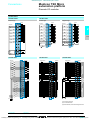
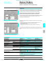
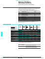
Modicon TSX Micro
and PL7 software
Automation platform Modicon TSX Micro and PL7 software
01-04
Catalogue
January
04
Courtesy of Steven Engineering, Inc. ● 230 Ryan Way, South San Francisco, CA 94080-6370 ● General Inquiries: (800) 670-4183 ● www.stevenengineering.com
efesotomasyon - telemecanique inverter
Courtesy of Steven Engineering, Inc. ● 230 Ryan Way, South San Francisco, CA 94080-6370 ● General Inquiries: (800) 670-4183 ● www.stevenengineering.com
efesotomasyon - telemecanique inverter
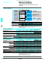
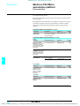
General contents
Modicon TSX Micro
automation platform
1 - Modicon TSX Micro PLC
Selection guide . . . . . . . . . . . . . . . . . . . . . . . . . . . . . . . . . . . . . . . . . . . . . page 1/2
b TSX 37-05/08/10/21/22 PLCs . . . . . . . . . . . . . . . . . . . . . . . . . . . . . . . . . page 1/4
2- Discrete I/O
Selection guide I/O modules . . . . . . . . . . . . . . . . . . . . . . . . . . . . . . . . . . page 2/2
b 2.1 - Discrete I/O modules. . . . . . . . . . . . . . . . . . . . . . . . . . . . . . . . . . . . page 2/6
b 2.1 - Safety module . . . . . . . . . . . . . . . . . . . . . . . . . . . . . . . . . . . . . . . . page 2/18
b 2.1 - Extension module for Nano PLCs . . . . . . . . . . . . . . . . . . . . . . . . page 2/24
Selection guide Telefast® 2 pre-wired system . . . . . . . . . . . . . . . . . . . page 2/26
b 2.2 - Telefast 2 pre-wired system . . . . . . . . . . . . . . . . . . . . . . . . . . . . . page 2/32
b 2.2 - Tego installation system . . . . . . . . . . . . . . . . . . . . . . . . . . . . . . . . page 2/44
Selection guide Phaseo power supplies for DC control circuits . . . . page 2/50
b 2.3 - Phaseo power supplies . . . . . . . . . . . . . . . . . . . . . . . . . . . . . . . . . page 2/52
3 - Application-specific modules
Selection guide analogue I/O . . . . . . . . . . . . . . . . . . . . . . . . . . . . . . . . . . page 3/2
b 3.1 - Integrated channels and analogue I/O modules . . . . . . . . . . . . . . . page 3/4
b 3.1 - Process control of semi-continuous processes . . . . . . . . . . . . . . . page 3/10
Selection guide counter/positionning modules . . . . . . . . . . . . . . . . . . page 3/14
b 3.2 - Integrated channels and counter/positioning modules . . . . . . . . . page 3/16
b 3.2 - Absolute encoder positioning module . . . . . . . . . . . . . . . . . . . . . . page 3/22
4 - Communication
Selection guide . . . . . . . . . . . . . . . . . . . . . . . . . . . . . . . . . . . . . . . . . . . . . page 4/2
b 4.1 - Ethernet TCP/IP network . . . . . . . . . . . . . . . . . . . . . . . . . . . . . . . . . page 4/6
b 4.2 - CANopen machine bus . . . . . . . . . . . . . . . . . . . . . . . . . . . . . . . . . page 4/22
b 4.2 - AS-Interface sensors/actuators bus . . . . . . . . . . . . . . . . . . . . . . . page 4/26
b 4.3 - Modbus Plus network . . . . . . . . . . . . . . . . . . . . . . . . . . . . . . . . . . page 4/34
b 4.3 - Modbus bus. . . . . . . . . . . . . . . . . . . . . . . . . . . . . . . . . . . . . . . . . . page 4/38
b 4.4 - Fipway network . . . . . . . . . . . . . . . . . . . . . . . . . . . . . . . . . . . . . . . page 4/46
b 4.4 - Fipio bus Agent function . . . . . . . . . . . . . . . . . . . . . . . . . . . . . . . . page 4/50
b 4.4 - Uni-Telway bus . . . . . . . . . . . . . . . . . . . . . . . . . . . . . . . . . . . . . . . page 4/60
b 4.4 - Asynchronous serial links . . . . . . . . . . . . . . . . . . . . . . . . . . . . . . . . page 4/64
5 - PL7 software and Magelis terminals
Selection guide PL7 programming software . . . . . . . . . . . . . . . . . . . . . page 5/2
b PL7 Micro/Junior/Pro programming software . . . . . . . . . . . . . . . . . . . . . page 5/2
b PL7 SMC, PL7 DIF, SDKC, PL7 FUZ optional software . . . . . . . . . . . . page 5/20
b FTX 117 Adjust terminal . . . . . . . . . . . . . . . . . . . . . . . . . . . . . . . . . . . . page 5/28
Selection guide Magelis terminals. . . . . . . . . . . . . . . . . . . . . . . . . . . . . page 5/30
6 - Services
b Documentation and power consumption of TSX Micro PLC modules . . . page 6/2
b Standards, certifications and community regulations . . . . . . . . . . . . . . . page 6/6
b Schneider Electric worldwide. . . . . . . . . . . . . . . . . . . . . . . . . . . . . . . . . page 6/10
b Product references index. . . . . . . . . . . . . . . . . . . . . . . . . . . . . . . . . . . . page 6/16
3
Courtesy of Steven Engineering, Inc. ● 230 Ryan Way, South San Francisco, CA 94080-6370 ● General Inquiries: (800) 670-4183 ● www.stevenengineering.com
efesotomasyon - telemecanique inverter
1
SS301-EN_Ver1.0.fm/0
Courtesy of Steven Engineering, Inc. ● 230 Ryan Way, South San Francisco, CA 94080-6370 ● General Inquiries: (800) 670-4183 ● www.stevenengineering.com
efesotomasyon - telemecanique inverter
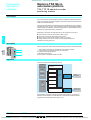
Contents
1 - Modicon TSX Micro
automation platform
1 - Modicon TSX Micro PLCs
Selection guide PLCs . . . . . . . . . . . . . . . . . . . . . . . . . . . . . . . . . . . . . . . . page 1/2
b TSX 37 05 PLCs . . . . . . . . . . . . . . . . . . . . . . . . . . . . . . . . . . . . . . . . . . . page 1/4
1
b TSX 37 08 PLCs . . . . . . . . . . . . . . . . . . . . . . . . . . . . . . . . . . . . . . . . . . . page 1/5
b TSX 37 10 PLCs . . . . . . . . . . . . . . . . . . . . . . . . . . . . . . . . . . . . . . . . . . . page 1/6
b TSX 37 21/22 PLCs. . . . . . . . . . . . . . . . . . . . . . . . . . . . . . . . . . . . . . . . . page 1/7
b Functions, memory structure . . . . . . . . . . . . . . . . . . . . . . . . . . . . . . . . . . page 1/8
b Characteristics. . . . . . . . . . . . . . . . . . . . . . . . . . . . . . . . . . . . . . . . . . . . page 1/13
b References . . . . . . . . . . . . . . . . . . . . . . . . . . . . . . . . . . . . . . . . . . . . . . page 1/15
b Dimensions, mounting . . . . . . . . . . . . . . . . . . . . . . . . . . . . . . . . . . . . . . page 1/17
SS301-EN_Ver1.0.fm/1
Courtesy of Steven Engineering, Inc. ● 230 Ryan Way, South San Francisco, CA 94080-6370 ● General Inquiries: (800) 670-4183 ● www.stevenengineering.com
efesotomasyon - telemecanique inverter
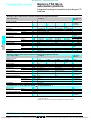
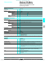
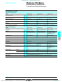
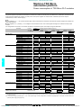
Selection guide
Modicon TSX Micro
automation platform
1
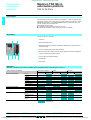
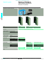
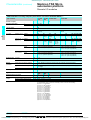
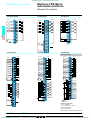
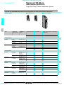
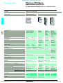
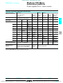
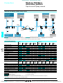
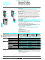
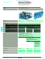
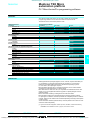
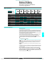
TSX 37 05/08/10/21/22 PLCs
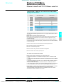
Applications
For low to medium complexy control systems
1
No. of slots
No. of discrete I/O,
connection
Base
3 (2 equipped with discrete I/
O module)
Extension
2 (1 equipped with discrete I/
O module)
–
Per HE10 connector (1)
Per terminal block (1)
92
60 (28 I/O)
120
88 (56 I/O)
2 (1 equipped with discrete I/O
2
Remote I/O (except bus)
–
App-spec. inputs/outputs Integrated analogue
Analogue
Integrated counting
–
2 half-format modules (4, 8 I - 2, 4 O ou 4 I/2 O)
2 x 500 Hz channels using discrete inputs
–
124 (28 I/O)
96 inputs/outputs via 1 half-format
Counting
Communication
2 half-format modules (1, 2 x 40 kHz channels, 2 x 500 kHz channels, 1 x 1 MHz SSI channel)
1 x integrated RS 485 channel (TER port)
Field bus connections
AS-Interface master
Fipio agent function
CANopen master
–
–
–
1 AS-Interface bus half-format
Bus and serial link
connections
Integrated Modbus (RTU)
Integrated Uni-Telway
Modbus/Uni-Telway/Fipio
1 slave port (TER port)
1 voie maître/esclave (prise TER)
–
1 master/slave port (TER port)
Integrated character mode
1 TER port
Ethernet TCP/IP
Nertwork cards
–
–
Network connections
1 Ethernet TCP/IP external module
Process control
Control loops, 3 integrated functions : PID, PWM (pulse width modulation) et SERVO (discrete valve
Real-time clock
–
Integrated (second, minute, hour,
11 Kwords
–
–
14 Kwords
Memory capacity
Integrated RAM
Extension (2)
Data storage
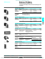
Power supply
a 100/240 V (integrated c 24 V sensor power supply)
Type of PLCs
TSX 37 05 028DR1
Pages
1/15
TSX 37 08 056DR1
TSX 37 10 028pR1
(1) The value in bracket and in italics corresponds to number of I/O providing with the basic PLC configuration.
(2) For program and constants zones.
1/2
Courtesy of Steven Engineering, Inc. ● 230 Ryan Way, South San Francisco, CA 94080-6370 ● General Inquiries: (800) 670-4183 ● www.stevenengineering.com
efesotomasyon - telemecanique inverter
1
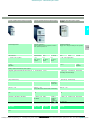
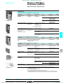
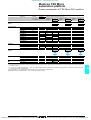
For control systems which require a signifiant
amount of processing (program and data) and:or
communication
module)
For control systems which require low-cost
analogue I/O and fast counting functions
1
3 (non-equipped with discrete I/O module)
2
184 (28 ou 64 I/O depending on model)
–
248
160
module connecting to 4 Nano componants (PLC base or discrete/analogue extension, 200 m max.)
8 inputs 8 bits, 1 ouput 8 bits
4 half-format modules (4, 8 I - 2, 4 O ou 4 I/2 O)
2 x 500 Hz channels using discrete inputs and
2 integrated 10 kHz channels
4 half-format modules (1, 2 x 40 kHz channels, 2 x 500 kHz channels, 1 x1MHz SSI channel)
1 x integrated RS 485 channel (AUX port)
module (31 slaves)
1 PCMCIA card in slot for a communication card
1 PCMCIA card in slot for a communication card
1 master/slave port (AUX port)
1 master/slave port (AUX port)
1 PCMCIA card in slot for a communication card: serial link, Uni-Telway bus, Modbus bus or Fipio bus
(agent)
1 AUX port
or Modem (PPP) RS 232C serial link
1 PCMCIA card in slot for a communication card: Fipway network or Modbus Plus network
control) with MMI on CCX 17 operator panel (control and adjustment of 9 loops maximum)
day, month and year)
20 Kwords
128 Kwords
128 Kwords
c 24 V non-isolated
TSX 37 10 128Dp1
TSX 37 10
1ppDTK1
TSX 37 21 101
a 100/240 V (integrated c 24 V sensor power
supply)
c 24 V non-isolated
TSX 37 21 001
TSX 37 22 101
TSX 37 22 001
1/3
Courtesy of Steven Engineering, Inc. ● 230 Ryan Way, South San Francisco, CA 94080-6370 ● General Inquiries: (800) 670-4183 ● www.stevenengineering.com
efesotomasyon - telemecanique inverter
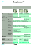
Modicon TSX Micro
automation platform
Presentation,
description,
selection
1
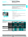
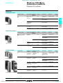
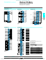
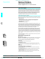
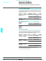
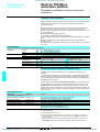
TSX 37 05 PLCs
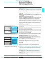
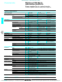
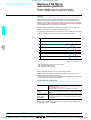
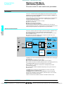
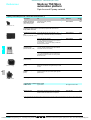
Presentation
1
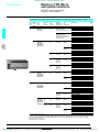
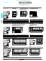
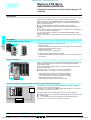
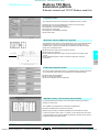
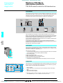
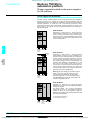
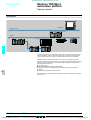
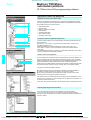
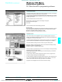
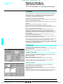
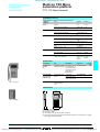
The TSX 37 05 PLC comprises a rack which integrates a 100/240 V power supply,
a processor including a 11 Kword memory (program, data and constants), 1 Flash
EPROM backup memory, a TSX DMZ 28DR discrete I/O module (16 inputs and
12 relay outputs) and an available slot.
The available slot can accept:
b 1 standard format discrete I/O module of any type.
b 2 half format discrete I/O, safety, analog I/O or counter modules.
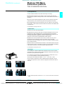
Description
The TSX 37 05 PLC comprises:
2
3
1
1 2-slot rack.
2 Centralized display block.
3 Terminal port (TER) (Uni-Telway master/slave, Modbus RTU slave protocol or
characters string).
4 Cover for accessing the power supply terminals.
5 Discrete module with 16 inputs and 12 outputs, placed in the first slot (positions
1 and 2). Including screw terminal block.
6 Cover for accessing optional battery.
4
8 6
5
7 Available slot.
7
8 Reset button.
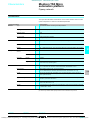
Selection
Selection of modules to be inserted in addition to the 16-input/12-output module present at rack no. 1
Type of module to be inserted
Discrete Inputs/Outputs
Preventa safety module
Analogue I/O
Counter/positioning channels
Max number of modules
1
2
Format
Standard
Half
Connection
Connector
Term.blk
8 inputs
12 inputs
32 inputs
4 outputs
8 outputs
32 outputs
16 inputs/outputs
28 inputs/outputs
64 inputs/outputs
4 or 8 inputs
2 or 4 outputs
4 inputs and 2 outputs
1 incremental code
channel
2 incremental code
channels
1 absolute encoder
channel
Possible insertion
Functions:
pages 1/8 and 1/9
Characteristics:
pages 1/13 and 1/14
References:
pages 1/15 and 1/16
Dimensions, mounting:
page 1/17
1/4
Courtesy of Steven Engineering, Inc. ● 230 Ryan Way, South San Francisco, CA 94080-6370 ● General Inquiries: (800) 670-4183 ● www.stevenengineering.com
efesotomasyon - telemecanique inverter
Presentation,
description,
selection (continued)
Modicon TSX Micro
automation platform
1
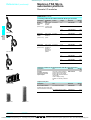
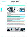
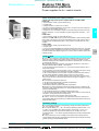
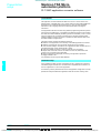
TSX 37 08 PLCs
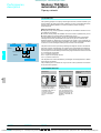
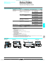
Presentation
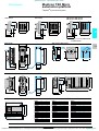
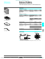
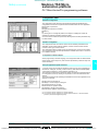
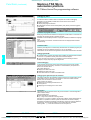
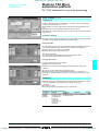
The TSX 37 08 PLC comprises a rack which integrates a 100/240 V power supply,
a processor including a 11 Kword memory (program, data and constants), 1 Flash
EPROM backup memory, 2 TSX DMZ 28DR discrete I/O modules (16 inputs and
12 relay outputs) and an available slot.
The available slot can accept:
b 1 standard format discrete I/O module of any type.
b 2 half format discrete I/O, safety, analog I/O or counter modules.
1
Description
2
3
The TSX 37 08 PLC comprises:
1
1 3-slot rack.
2 Centralized display block.
3 Terminal port (TER) (Uni-Telway master/slave, Modbus RTU slave protocol or
characters string).
4 Cover for accessing the power supply terminals.
5 Two discrete modules with 16 inputs and 12 outputs, placed in the first and second
slot (positions 1 to 4). Including screw terminal block.
6 Cover for accessing optional battery.
4
8
1
5
7
7 Available slot.
8 Reset button.
Selection
Selection of modules to be inserted in addition to the 16-input/12-output module present at rack no. 1
Type of module to be inserted
Discrete Inputs/Outputs
Preventa safety module
Analog I/O
Counter/positioning channels
Max number of modules
1
2
Format
Standard
Half
Connection
Connector
Term.blk
8 inputs
12 inputs
32 inputs
4 outputs
8 outputs
32 outputs
16 inputs/outputs
28 inputs/outputs
64 inputs/outputs
4 or 8 inputs
2 or 4 outputs
4 inputs and 2 outputs
1 incremental code
channel
2 incremental code
channels
1 absolute encoder
channel
Possible insertion
Functions:
pages 1/8 and 1/9
Characteristics:
pages 1/13 and 1/14
References:
pages 1/15 and 1/16
Dimensions, mounting:
page 1/17
1/5
Courtesy of Steven Engineering, Inc. ● 230 Ryan Way, South San Francisco, CA 94080-6370 ● General Inquiries: (800) 670-4183 ● www.stevenengineering.com
efesotomasyon - telemecanique inverter
Modicon TSX Micro
automation platform
Presentation,
description,
selection (continued)
1
TSX 37 10 PLCs
Presentation
1
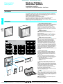
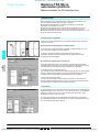
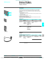
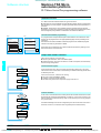
Compact and modular TSX 37 10 PLCs differ in their supply voltage and the type of
discrete I/O module fitted in the first slot.
Each TSX 37 10 configuration comprises a rack which integrates a power supply
(c 24 V or a 100/240 V), a processor including a 14 Kword RAM memory (program,
data and constants), a Flash EPROM backup memory, a real-time clock, a discrete
I/O module (28 or 64 I/O) and an available slot. A TSX RKZ 02 mini extension rack
enables the number of slots to be increased by 2 (4 positions).
Each available slot can accept:
b 1 standard format discrete I/O module of any type.
b 2 half format discrete I/O, safety, analog I/O or counter modules.
Also, TSX 37 10 PLCs can connect to the Ethernet network TCP/IP or to a Modem
via the TSX ETZ 410/510 external stand-alone module.
Description
2
4
3
1
12 6
5
7
8
11
10 9
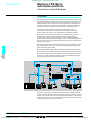
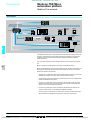
TSX 37 10 PLCs and the TSX RKZ 02 mini extension rack comprise:
1 2-slot base rack.
2 Centralized display block.
3 Terminal port (TER) (Uni-Telway, Modbus RTU master/slave protocol or
characters string).
4 Cover for accessing the power supply terminals.
5 28 or 64 discrete I/O module, placed in the first slot (positions 1 and 2).
6 Cover for accessing optional battery.
7 Mini extension rack with 2 available slots -(positions 5 to 8).
8 LED showing presence of c 24 V.
9 Power supply terminals protected by removable cover, to connect an auxiliary
c 24 V power supply if PLCs are supplied with a 100/240 V.
10 Earth terminal.
11 Connectors to the base PLC.
12 Reset button.
Selection
TSX 37 10 base PLC selection
Power supply
c 24 V
I/O module integrated in 1st slot
Number of inputs
c 24 V
a 110/120 V
16
16
16
a 110/240V
32
16
16
Connection
HE 10
Connector
Number of outputs
Solid state c
Relay
24 V
12
12
12
32
12
12
Reference
Screw terminal
block
TSX 37 10 128DT1
TSX 37 10 128DTK1
TSX 37 10 128DR1
TSX 37 10 164DTK1
TSX 37 10 028AR1
TSX 37 10 028DR1
Selection of modules to be inserted (3 slots available, that is a maximum of 6 positions)
Type of module to be inserted
Discrete Inputs/Outputs
Maximum number of modules (1)
1
2
4
8 inputs
12 inputs
32 inputs
4 outputs
8 outputs
32 outputs
16 inputs/outputs
28 inputs/outputs
64 inputs/outputs
Preventa safety module
AS-Interface bus or I/O extension
Analog I/O
4 or 8 inputs
2 or 4 outputs
Counter/positioning
1 or 2 incremental encoder
channels
channels
1 absolute encoder channel
Communication
Ethernet TCP/IP or external
Modem
6
Format
Stand.
Half
Connection
Connect. Term.blk
(2)
(2)
(2)
(2)
(3)
External module
Possible selection or insertion
(1) With TSX RKZ 02 mini extension rack.
(2) This includes a standard format module to be inserted in the 1st slot of the PLC.
(3) The remote discrete I/O extension modules and AS-Interface bus modules are installed in
position 4 which means that their use is mutually exclusive.
Functions:
pages 1/8 and 1/9
Characteristics:
pages 1/13 and 1/14
References:
pages 1/15 and 1/16
Dimensions, mounting:
page 1/17
1/6
Courtesy of Steven Engineering, Inc. ● 230 Ryan Way, South San Francisco, CA 94080-6370 ● General Inquiries: (800) 670-4183 ● www.stevenengineering.com
efesotomasyon - telemecanique inverter
Modicon TSX Micro
automation platform
Presentation,
description,
selection (continued)
1
TSX 37 21/22 PLCs
Presentation
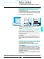
Modular TSX 37 21/22 PLCs differ in their supply voltage and/or the possibility of fast
counting and analogue functions integrated on the base.
Each PLC comprises: a 3-slot rack which integrates a power supply (c 24 V or
a 100/240 V), a processor including a 20 Kword RAM memory (program, data
and constants), 1 Flash EPROM backup memory, 2 slots for a PCMCIA card
(1 communication card and 1 memory extension card of 128 Kwords maximum) and
a real-time clock. A TSX RKZ 02 mini extension rack enables the number of slots
to be increased by 2 (4 positions).
Each available slot can accept:
b 1 standard format discrete I/O module.
b 2 half format discrete I/O, safety, analog I/O or counter modules.
Also, TSX 37 21/22 PLCs can connect to the Ethernet network TCP/IP or to a modem
via the TSX ETZ 410/510 external stand-alone module.
1
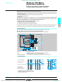
Description
TSX 37 21/22 PLCs and the TSX RKZ 02 mini extension rack comprise:
9
3
4
5 2
10
1
14
6
7
8 15
11 1 3-slot base rack (positions 1 to 6).
2 Slot reserved for a standard format module.
3 Centralized display block.
4 Terminal port (TER) (Uni-Telway, Modbus RTU master/slave protocol or
characters string).
5 Man-machine interface port labeled AUX.
6 Cover for accessing the power supply terminals.
7 Slot for a PCMCIA memory extension card.
8 Slot for a PCMCIA communication card.
9 On TSX 37 22, SUB-D connectors type for integrated analogue and counter
functions.
10 Mini extension rack with 2 available slots (positions 7 to 10).
13 12 11 LED showing voltage presence of c 24 V.
12 Power supply terminals protected by removable cover, to connect an auxiliary
c 24 V power supply if PLCs are supplied with a 100/240 V.
13 Earth terminal.
14 Connectors to the base PLC.
15 Reset button.
Selection
Selection of modules to be inserted (5 slots available, that is a maximum of 9 positions)
Type of module to be inserted
Maximum number of modules (1)
1
3
4
5
Discrete Inputs/
Outputs
8 inputs
12 inputs
32 inputs
4 outputs
8 outputs
32 outputs
16 inputs/outputs
28 inputs/outputs
64 inputs/outputs
Preventa safety module
AS-Interface bus or I/O extension
Analog I/O
4 or 8 inputs
2 or 4 outputs
2 inputs and 4 outputs
Counting/
1 or 2 incremental encoder channels
positioning
1 absolute encoder channel
Communication Serial link
(PCMCIA card on CANopen bus
processor)
Modbus bus
Fipio Agent bus
Uni-Telway bus
Modbus Plus network
Fipway network
Communication Ethernet TCP/IP or external Modem
9
(3)
(2)
Format
Stand.
Half
Connection
Connect. Term.blk
(2)
(2)
(2)
(2)
(2)
(2)
(2)
(3)
(4)
(4)
External module
Possible insertion
(1) With TSX RKZ 02 mini extension rack.
(2) Comprises a standard format module to be placed in 1st slot of the PLC.
(3) The remote discrete I/O extension modules and AS-interface bus modules are installed in
position 4 which means that their use is mutually exclusive.
(4) With a maximum of 2 (TSX AMZ 600/ASZ 200) modules in the base.
Functions:
pages 1/8 and 1/9
Characteristics:
pages 1/13 and 1/14
References:
pages 1/15 and 1/16
Dimensions, mounting:
page 1/17
1/7
Courtesy of Steven Engineering, Inc. ● 230 Ryan Way, South San Francisco, CA 94080-6370 ● General Inquiries: (800) 670-4183 ● www.stevenengineering.com
efesotomasyon - telemecanique inverter
Modicon TSX Micro
automation platform
Functions
1
TSX 37 05/08/10/21/22 PLCs
Functions
Discrete inputs/outputs
1
The range of in-rack discrete I/O modules offers several possibilities for meeting
requirements:
b Cost-effective connection where a c 24 V solution is required (mixed I/O modules
with HE type 10 connectors for direct connection to pre-actuators in the device using
cables with flying leads or direct connection to the TELEFAST2 pre-wired system).
b Connection to the screw terminal block on the front panel of mixed I/O modules.
A set of half format modules enable the PLC configuration to be adapted as closely
as possible to the user's requirements in terms of number, range of I/O and type of
connection.
For further details, see pages 2/6 to 2/17.
The TSX DPZ 10D2A Preventa type safety relay module provides a monitoring
function for the emergency stop pushbuttons or limit switches, and is adapted to
conform to the safety requirements stipulated in EN 954-1.
For further details, see pages 2/18 to 2/23.
Remote discrete I/O extension module
TSX 37 10/21/22 Micro PLCS offer two different possibilities for extending the I/O:
b Either with the TSX STZ 10 remote discrete I/O extension module. The discrete I/
O of 4 Nano PLCs can be used at a distance of up to 200m (one of which can be a
Nano extension PLC).
These Nano PLCs can be used as remote discrete I/O or local slave PLCs.
For further details, see pages 2/24 et 2/25.
b The AS-Interface sensor/actuator bus. TSX Micro PLCs are connected to the
AS-Interface bus via an AS-Interface master module. In this case, the PLC becomes
the master station on the bus and manages a maximum of 248 I/O over a distance
of up to 100 m (200 m with a repeater).
For further details, see pages 4/26 to 4/29.
b The CANopen machine bus. The communication of the Micro TSX 37 21/22 PLCs
enables the connectivity to the CANopen machine bus. It is appeared as a PCMCIA
card equipped with a cable (length 0.5m) and a tap junction (with 9-way SUB-D
connector). This TSX CPP 110 kit allows the direct linking to the bus and ensures the
role of the master on the CANopen bus. The PCMCIA card is inserted into the
reserved slot for communication card, available on the TSX 37 21 and TSX 37 22.
For further details, see pages 4/22 to 4/25.
Analogue I/O and process control
TSX Micro PLCs offer several ways of performing analogue processing:
b For data input or commands which do not need a high resolution level, using I/O
integrated in TSX 37 22 PLCs.
b For precise measurement and commands, using TSX AEZ/ASZ/AMZ ppp half
format analogue I/O modules.
b To locate analog I/O remotely via the TSX STZ 10 rackmaster module with
TSX 37 10/21/22 PLCs. The latter enables the use of three TSX AMN 400p analog
extensions, each equipped with 3 analogue inputs and one analog output.
For further details, see pages 3/5 and 3/6.
TSX Micro PLCs have, as standard, process control functions which can be
accessed by the user via the PL7 Micro, PL7 Junior or PL7 Pro programming
software.
For further details, see pages 3/10 to 3/13.
Description:
pages 1/4 to 1/7
Characteristics:
pages 1/13 and 1/14
References:
pages 1/15 and 1/16
Dimensions, mounting:
page 1/17
1/8
Courtesy of Steven Engineering, Inc. ● 230 Ryan Way, South San Francisco, CA 94080-6370 ● General Inquiries: (800) 670-4183 ● www.stevenengineering.com
efesotomasyon - telemecanique inverter
Functions (continued)
Modicon TSX Micro
automation platform
1
TSX 37 05/08/10/21/22 PLCs
Counting/positioning
Counter modules TSX Micro PLCs offer several ways of counting:
1
b Using 500 Hz discrete inputs (2 up/down counter channels with upcounting,
downcounting or up/down counting functions, with or without detection of direction of
operation).
b 10 kHz counter channels integrated into TSX 37 22 PLC bases (2 10 kHZ fast
counter channels, with 1 channel having down-counting functions as above).
b Counting/positioning TSX CTZ modules pA, from 40...500 kHz or TSX CTZ 2B,
from 200 kHz...1 MHz. These half format modules are inserted in the available slots
in the base rack.
For further details, see pages 3/16 to 3/25.
Communication
TSX Micro PLCs offer several possibilities:
b Integrated communication which offers cost-effective dialogue functions via the
terminal port for TSX 37 05/08/10 PLCs or via the terminal and man-machine
interface ports for TSX 37 21/22 PLCs. These RS 485 type non-isolated links use
Uni-Telway master/slave, Modbus RTU slave or character string.
Also TSX 37 10/21/22 PLCs integrate Modbus master protocol.
b PCMCIA format communication card for TSX 37 21/22 PLCS. They have a
dedicated slot for the PCMCIA format communication card ("Full-duplex"
asynchronous serial link, CANopen bus, Fipio bus, Uni-Telway or Modbus, Modbus
Plus or Fipway network).
b Ethernet TCP/IP 10/100 MHz external modules. This external module connects to
the terminal port of TSX 37 10/21/22 PLCs and has Uni-TE and Modbus messaging.
It also allows connection to an external modem using PPP protocol.
For further details, see pages 4/6 to 4/21.
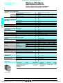
Fan modules
TSX FAN ppP fan modules installed above TSX Micro PLCs ensure a forced air
convection, which creates a uniform ambient temperature within the enclosure and
eliminates any hot spots which might exist.
Fan modules are required when the ambient temperature is between 60 °C and
70 °C. Forced ventilation is used to eliminate hot spots (1).
Three types of fan module are available: c 24 V, a 110 V and a 220 V.
One fan module is required for a TSX 37 05/08/10/21/22 configuration, two fan
modules are required for a TSX 37 10/21/22 configuration with the TSX RKZ 02
mini rack.
TSX FAN ppP
TSX 37 05/08/10
TSX 37 10 + TSX RKZ 02
TSX 37 08/21/22
TSX 37 21/22 + TSX RKZ 02
Description:
pages 1/4 to 1/7
Characteristics:
pages 1/13 and 1/14
(1) For an ambient temperature of between 25 °C…60 °C, the use of fan modules increases the
MBTF.
References:
pages 1/15 and 1/16
Dimensions, mounting:
page 1/17
1/9
Courtesy of Steven Engineering, Inc. ● 230 Ryan Way, South San Francisco, CA 94080-6370 ● General Inquiries: (800) 670-4183 ● www.stevenengineering.com
efesotomasyon - telemecanique inverter
Memory structure
Modicon TSX Micro
automation platform
1
TSX 37 05/08/10/21/22 PLCs
Memory structure
1
The memory structure of TSX Micro PLCs consists of two distinct zones:
b An internal RAM memory designed to receive the application (data, program and
constants) of
v 11 Kwords for TSX 37 05/08 PLCs,
v 14 Kwords for the TSX 37 10 PLC,
v 20 Kwords for TSX 37 21/22 PLCs.
b A Flash EPROM memory of:
v 12 Kwords for TSX 37 05/08 PLCs,
v 16 Kwords for TSX 37 10/21/22 PLCs
designed to back up the application program (11 or 14 Kwords maximum) and to
back up 1024 %MW internal words in the event of a battery failure or no battery.
For TSX 37 21/22 PLCs, the internal RAM memory can be extended via a 32, 64 or
128 Kwords PCMCIA memory card, either RAM or Flash EPROM. The same
memory card incorporated the possibility of contained a storage zone for additional
data, e.g. for production data and manufacturing recipes.
PCMCIA memory extension cards for TSX 37 21/22 PLCs
These cards can be used to extend the PLC internal memory for storing the
application program and constants.
Two types of memory card are available:
b Battery-backed RAM type memory card
Used in particular during application program creation and debugging, this card
enables all application transfer and modification services in online mode.
The memory is backed up by a removable battery integrated in the memory card.
b Flash EPROM type memory card
Used when the debugging of the application program is complete, this card enables
one global transfer only of the application and avoids the problems of backup via
battery.
A third type of card can also be used to store additional data:
b Battery-backed RAM type memory card or battery-backed RAM and Flash
EPROM
Used particularly in association with the Modem link, these are used to extend the
processor's internal memory, and also to store recipe or data log for later consultation
via a telephone link.
The RAM memory is backed up by a removable battery integrated in the
memory card.
Another type of PCMCIA memory card is available:
b Backup type memory card (for TSX 37 21/22 PLCs)
Previously loaded with the application program, this card is used to reload the
application program into the internal RAM memory and the internal Flash EPROM
memory of the processor, without requiring the use of a programming terminal.
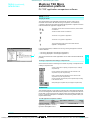
Program loader
The TSX PRG LDR module is designed to simplify duplicating or updating
applications on Nano and TSX Micro PLCs without the need for a programming
terminal. An application (15 Kwords maximum in internal RAM) can be transferred
from a PLC in the TSX PRG LDR module (and saved within it), then transferred from
the TSX PRG LDR module to the PLC.
1
The front panel of the TSX PRG LDR module comprises:
1 A cord for connecting to the PLC terminal port.
2 Four operation indicator LEDs.
3 A W/R button which selects the program transfer direction (PLC V module or
module V PLC).
4 A GO button to start the transfer.
5 A Write Only switch which prevents PLC V module transfer.
6 A Program Protect switch which protects the PLC application as read-only after
the transfer.
2
3
6
Functions:
pages 1/8 and 1/9
5
4
Characteristics:
pages 1/13 and 1/14
References:
pages 1/15 and 1/16
Dimensions, mounting:
page 1/17
1/10
Courtesy of Steven Engineering, Inc. ● 230 Ryan Way, South San Francisco, CA 94080-6370 ● General Inquiries: (800) 670-4183 ● www.stevenengineering.com
efesotomasyon - telemecanique inverter
Memory structure (continued) Modicon TSX Micro
automation platform
1
TSX 37 05/08/10/21/22 PLCs
Application memory
The application memory is divided into memory zones, which are physically shared
between the internal RAM memory and the PCMCIA memory card (if the TSX 37 21/
22 PLC has a memory card):
1
b The application data zone which is always is the internal RAM memory.
b The application program zone in the internal RAM memory or on the PCMCIA
memory card.
b The constants zone in the internal RAM memory or on the PCMCIA memory card.
b The Flash EPROM zone for the application program backup, the constants and
1 K internal words.
b The file storage zone in the PCMCIA memory card.
If the content of the RAM memory is lost (battery fault or no battery) then the content
of the Flash EPROM memory (program, constants and 1 K internal words) is
automatically transferred to the internal RAM memory. The backup copy of the
application in the Flash EPROM memory requires that the PLC does not have a
PCMCIA memory extension card and that the size of the program and the constants
does not exceed 16 Kwords.
Two types of application memory organization are possible for TSX Micro PLCs
depending on whether the PLC is equipped with a memory extension in the form of a
PCMCIA card:
TSX 37 05/08/10/21/22 (without PCMCIA card)
Application in the internal RAM
The application is loaded entirely in the battery-backed internal RAM of the processor
with a capacity of:
Backup copy
Flash
EPROM
11/14/20
Kwords
Internal
RAM
Program
12/16
Kwords
Data
Program and constants
Constants
1 Kwords int. %MW
1 Application data (17.5 Kwords maximum).
2 Descriptor and exedutable code for tasks.
3 Constant words, initial values and configuration.
Backup copy
Flash
EPROM
PCMCIA
card
1
2
3
4
128 32/64/128
16
Kwords Kwords Kwords
Internal
RAM
20
Kwords
TSX 37 21/22 (with a PCMCIA card)
Data
1 Kwords int. %MW
Program
Constants
Additional data storage
Application data (17.5 Kwords maximum).
Descriptor and exedutable code for tasks.
Constant words, initial values and configuration.
According to the PCMCIA card model.
b 11 Kwords for TSX 37 05/08, shared, for example: as 3 Kwords of application data
and 8 Kwords of the program and its constants.
b 14 Kwords for TSX 37 10, shared, for example: as 500 words of application data
and 13.5 Kwords of the program and its constants.
b 20 Kwords for TSX 37 21/22, shared, for example: as 4 Kwords of application data
and 16 Kwords of the program and its constants.
Application in the internal Flash EPROM
The total volume is equal to the application volume in RAM, limited to 11 Kwords
or 15 Kwords, to which the backup of the first 1024 data words (%MW) is added.
Application in the PCMCIA card
The PCMCIA memory card contains the program and the constants.
The additional data storage zone for 128 Kword data (available according to the
PCMCIA card model) can be used for distributed applications, for storing information
which can be consulted remotely via Modem.
This zone can also be used for storing manufacturing recipes.
Internal RAM data
The data zone can be extended to 20 Kwords, and is only held in the PLC
internal RAM.
Data backup
The first 1024 words are backed up by the PLC internal Flash EPROM memory.
PL7 Micro/Junior/Pro software aids the application designer in the management
of the structure and the occupation of memory space for TSX Micro PLCs.
Application protection
Whatever the PLC's memory structure is: application in internal RAM or on the
PCMCIA card, it is possible to protect the structure to prohibit access (reading or
program modification) in online mode using PL7 Micro/Junior/Pro software.
Backup application
Micro TSX 37 21/22 PLCs make it possible to save the 32 Kwords maximum
application (programs and constants) on a Backup TSX MFP BAK 032P memory
card. The internal RAM memory can thus be reloaded with the contents of this
Backup memory card.
This Backup function is not available if the application runs on a PCMCIA RAM or
Flash EPROM memory card.
Functions:
pages 1/8 and 1/9
Characteristics:
pages 1/13 and 1/14
References:
pages 1/15 and 1/16
Dimensions, mounting:
page 1/17
1/11
Courtesy of Steven Engineering, Inc. ● 230 Ryan Way, South San Francisco, CA 94080-6370 ● General Inquiries: (800) 670-4183 ● www.stevenengineering.com
efesotomasyon - telemecanique inverter
Modicon TSX Micro
automation platform
Centralized display,
description
1
TSX 37 05/08/10/21/22 PLCs
Centralized display
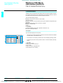
1
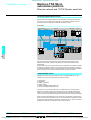
TSX Micro PLCs are equipped with a display block which groups together centrally
all the data required for the control, diagnostics and maintenance of the PLC and all
its modules, as well as simple man-machine interface functions.
The centralized display provides:
b Display of the local or remote I/O channel states
(I/O of Nano PLCs).
b Display of devices on the AS-Interface bus and AS-Interface bus diagnostics (see
page 4/26).
b Display of diagnostics of faulty channels or modules.
b Display of internal data:
v bits,
v bit strings,
v word strings,
v program variables (active steps, application information, etc).
b 4-digit multiple digital display.
Description
The centralized display block comprises:
2
1
BASE
EXT
64 16
R I/O
64 16
WRD
1 Three blocks of 32 LEDs representing the slots in which the modules are installed
in the base rack or mini extension rack.
RUN
0
4
8 12
0
4
8 12
0
4
8 12
1
5
9 13
1
5
9 13
1
5
9 13
2
6 10 14
2
6 10 14
2
6 10 14
3
7 11 15
3
7 11 15
3
7 11 15
0
4
8 12
0
4
8 12
0
4
8 12
1
5
9 13
1
5
9 13
1
5
9 13
2
6 10 14
2
6 10 14
2
6 10 14
3
7 11 15
3
7 11 15
3
7 11 15
Functions:
pages 1/8 and 1/9
3
DIAG
64 16
2 An information line consisting of LEDs which show the display operating modes.
TER
> 1s.
DIAG
I/O
ERR
BAT
Characteristics:
pages 1/13 and 1/14
4
3 A command push button which provides access to the various display operating
modes.
4
v
v
v
v
v
Five LEDs:
RUN, PLC run/stop,
TER, traffic on the terminal port,
I/O, I/O fault,
ERR, processor or application fault,
BAT, battery fault or no battery.
References:
pages 1/15 and 1/16
Dimensions, mounting:
page 1/17
1/12
Courtesy of Steven Engineering, Inc. ● 230 Ryan Way, South San Francisco, CA 94080-6370 ● General Inquiries: (800) 670-4183 ● www.stevenengineering.com
efesotomasyon - telemecanique inverter
Modicon TSX Micro
automation platform
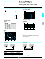
Characteristics
1
TSX 37 05/08/10/21/22 PLCs
Characteristics
TSX Micro PLCs have been developed to conform to the national and international
standards concerning electronic devices for industrial control systems:
b Specific requirements for programmable controllers: functional characteristics,
resistance, robustness, safety, etc. IEC 61131-2, CSA 22-2, UL 508.
b Merchant navy requirements from the main European bodies: BV, DNV, GL,
GOST, LR, RRS.
b European directives (low voltage, electromagnetic compatibility), e marking.
b Electrical qualities and self-extinguishing capacity of insulating materials:
UL 746C, UL 94, etc. See page 6/4.
1
Environmental characteristics (characteristics common to all TSX Micro PLC components)
Temperature
Relative
humidity
Operation
°C
0...+ 60 (+ 5...+ 55 conforming to IEC 61131-2), 0…+ 70 with TSX FAN ventilation modules
Storage
°C
- 25...+ 70 (conforming to IEC 61131-2)
Operation
10 %...95 %, without condensation
Storage
5 %..95 % conforming to IEC 61131/2 without condensation
Altitude
Mechanical
withstand
m
0…2000
Resistant to vibrations
Conforming to IEC 68-2-6, Fc test
Resistant to shocks
Conforming to IEC 68-2-27, Ea test
Resistant to
Withstand to electrostatic discharge
electrostatic
discharge
Resistance to HF Resistant to electromagnetic fields
interference
Resistant to rapid transient bursts
Conforming to IEC 1000-4-2, level 3 (1)
Conforming to IEC 1000-4-3, level 3 (1)
Conforming to IEC 1000-4-4, level 3 (1)
Resistant to shock waves
Conforming to IEC 1000-4-5
Resistant to damped oscillatory
waves
Resistance to LF interference
Conforming to IEC 1000-4-12
Conforming to IEC 61131-2
Power supply characteristics
Nominal
V
Power supply a
a 100...240
Power supply c
c 24
V
a 90…264
Frequency
Limit (including
ripple)
Nominal (limit)
Hz
50-60 (47-63)
c 19.2...30V
possible up to 34 V for 1 hr per 24 hrs
–
Current
Nominal input
A
y 0.7 (a 100 V), ≤ 0.3 (a 240 V)
2
Inrush (2)
A
y 60
y 60
y 1/2 period, repetition ≥ 1 s
y 10 ms, repetition u 1 s
Type of power supply
Primary
Voltage
Secondary
Micro-breaks
Accepted duration
Power
Total useful
(typical)
c 5 V output
W
24 (32 peak)
16 (18 peak)
A
2.8 (3.2 peak)
2.8 (3.2 peak)
Output c 24 VR
(for relay outputs)
c 24 V output
sensors
Overloads
A
0.5 (0.6 peak)
–
A
0.4 (0.6 peak)
–
Yes
Yes
Yes
Yes
2000 - 50/60 Hz
No isolation, 0 V internal connected to the PLC
ground
Output currents
Protection
integrated on the
outputs against
Short-circuits
Isolation
Dielectric
resistance
Primary/
secondary
V rms
(1) Minimum level in the test conditions defined by the standards.
(2) Values to be taken into account when starting up several devices at the same time or when
sizing protection devices.
Functions:
pages 1/8 and 1/9
References:
pages 1/15 and 1/16
Dimensions, mounting:
page 1/17
1/13
Courtesy of Steven Engineering, Inc. ● 230 Ryan Way, South San Francisco, CA 94080-6370 ● General Inquiries: (800) 670-4183 ● www.stevenengineering.com
efesotomasyon - telemecanique inverter
Modicon TSX Micro
automation platform
Characteristics (continued)
1
TSX 37 05/08/10/21/22 PLCs
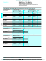
Processor chracteristics
1
Type of PLc
No. of slots
Functions
(Max.no.)
TSX 37 05
2
–
60 (28 I/O)
92
Basic
With extension rack, 2 slots
Discrete I/
Screw terminal block
O(1)
HE10 connector
64 channel modules
Integrated
Modules
Type of modules
Regulation
Counting
Integrated
channels (2) Modules
Type of modules
Discrete I/O
Integrated
Serial link
connections
Type of links
Networks
Ethernet TCP/IP
and bus
Fipway network,
connections Modbus Plus
AS-Interface bus
CANopen bus
Modbus bus,
Uni-Telway,
Characters string
Extension by Nano base and Nano
extension (200 m maxi)
Internal RAM which can
be backed up
Program and constants
Data storage
Max. data
Internal bits %Mi
storage size Internal words %MWi
Constants words %KWi
Application structure
Master task
Fast task
Event processing
Execution time Without
Boolean
for 1 instruction PCMCIA
On word or fixed-point
card
arithmetic
With
Boolean
PCMCIA
On word or fixed-point
card
arithmetic
No. of
Without
100 % boolean
K instructions PCMCIA
executed by ms card
65 % boolean and 35 %
numerical
With
100 % boolean
PCMCIA
card
65 % boolean and 35 %
numerical
Overhead système
Master task
88 (56 I/O)
120
TSX 37 10
2
4
124 (28 I/O)
184 (28 or 64 I/
O)
2
TSX 37 21
3
5
160 (–)
248 (–)
TSX 37 22
1
3
–
8 I et 1 O
2
4
Half format module 4 or 8 I, 2 or 4 O, 4 I/O
The number of loops is limited by the number of analogue modules and by the size of memory
–
2 channel 10 kHz
2
2 (3)
4 (3)
Half format module 1 or 2 channel 40/500 kHz, 1 channel SSI 1 MHz
2 channels 500 Hz
1 link with 1connector (TER) 19.2 Kbit/s
1 link with 2 connectors (TER and
AUX) 19,2 Kbit/s
Uni-Telway master/slave
Modbus slave RTU
Modbus master/slave RTU
Character mode
Character mode
–
1 (Ethernet TCP/IP external module or RS 232 Modem)
–
1 (4)
Analog I/O
Real time clock
Memory
Max.
capacity
TSX 37 08
3
–
–
–
1 Half format module (profil M2) (5)
1 (4)
1 (4)
1 (4)
–
1 half-format module (5) for 96 discrete I/O or
12 analogue I/O (4 Nano bases 24 I/O or 3 analogue
extensions 3 I/1 O)
–
Kwords 11
Kwords
Kwords
bits
Kwords
Words
14
20
128 with PCMCIA card
128
µs
µs
–
–
256
1 (6)
128 (6)
1
1
8
0,25
4,81
µs
µs
–
–
0,19
4,50
Kinst/
ms
Kinst/
ms
Kinst/
ms
Kinst/
ms
ms
3,03
5,88
0,25
0,27
–
4,00
–
0,266
1,9
1,6
1 (6), 17,5 with PCMCIA card
16 (where 1 has priority)
0,13
4,50
2,3
(1) The value in bracket and in italics corresponds to number of I/O providing with the basic PLC
configuration.
(2) Maximum number of couting/positioning channels, see page 3/16.
(3) TSX CTZpp counting/positioning modules, only in the TSX Micro base.
(4) PCMCIA to insert in the communication card slot
(5) The remote discrete I/O extension modules and AS-Interface bus modules are installed in
position 4 which means that their use is mutually exclusive.
(6) Default size, can be extended, but will have an adverse effect on the size of the application
program.
Functions:
pages 1/8 and 1/9
References:
pages 1/15 and 1/16
Dimensions, mounting:
page 1/17
1/14
Courtesy of Steven Engineering, Inc. ● 230 Ryan Way, South San Francisco, CA 94080-6370 ● General Inquiries: (800) 670-4183 ● www.stevenengineering.com
efesotomasyon - telemecanique inverter
Modicon TSX Micro
automation platform
References
1
TSX 37 05/08/10/21/22 PLCs
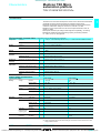
Basic TSX 37 05/08 PLC configurations (1 slot available)
Power supply
Integrated memories
RAM
a 100…240 V
TSX 37 05/10 p28pp1
11 Kwords
Flash
EPROM
12 Kwords
Weight
1 modules with Via screw
16 I c 24
terminal block
V,12 O relay
(supplied)
TSX 37 05 028DR1
kg
2.370
2 modules with Via screw
16 I c 24 V,
terminal block
12 O relay
(supplied)
TSX 37 08 056DR1
2.720
1
Basic TSX 37 10 PLC configurations (1 slot available)
Power supply
Integrated memories
RAM
c 24 V
14 Kwords
Flash
EPROM
15 Kwords
TSX 37 08 056 DR1
a 100…240 V
TSX 37 10 164DTK1
Integrated memory Discrete I/ Reference
O modules
Type
Connection
14 Kwords
15 Kwords
Integrated memory Discrete I/ Reference
O modules
Type
Connection
Weight
1 module with Via screw
16 I c 24 V
terminal block
12 Solid state O (supplied)
0.5 A
TSX 37 10 128DT1
kg
1.870
1 module with
16 I c 24 V
12 O relay
TSX 37 10 128DR1
1.900
Via screw
terminal block
(supplied)
1 module with Via HE 10 type TSX 37 10 128DTK1
16 I c 24 V
connector
12 Solid state O
0.5 A
1.740
1 module with Via HE 10 type TSX 37 10 164DTK1
32 I c 24 V
connector
32 Solid state O
0.1 A
1.820
1 module with
16 I a 115 V
12 O relay
Via screw
terminal block
(supplied)
TSX 37 10 028AR1
1.910
1 module with
16 I c 24 V
12 O relay
Via screw
terminal block
(supplied)
TSX 37 10 028DR1
1.910
Basic TSX 37 21/22 PLC configurations (3 slots available)
Power supply
c 24 V
a 100…240 V
Integrated memories
RAM
Flash
EPROM
20 Kwords
5 Kwords
Integrated functions
Reference
–
TSX 37 21 101
kg
1.720
8 analog inputs 0-10 V
1 analog output 0-10 V
1 Up/down counter 10 kHz
1 counter 10 kHz
TSX 37 22 101
1.750
–
TSX 37 21 001
1.720
8 analog inputs 0-10 V
1 analog output 0-10 V
1 Up/down counter 10 kHz
1 counter 10 kHz
TSX 37 22 001
1.750
Use
Number maximum
Reference
PLCs TSX 37 10/21/22
1 mini rack per PLC
TSX RKZ 02
20 Kwords
15 Kwords
TSX 37 22 p01
Weight
Mini extension rack
Capacity
2 slots (possibility of
4 positions)
Weight
kg
0.630
Documentation
TSX Micro base and module installation manual
See page 1/4
–
TSX RKZ 02
Description:
pages /4 to 41/7
Functions:
pages 1/8 and 1/9
Characteristics:
pages 1/13 and 1/14
Dimensions, mounting:
page 1/17
1/15
Courtesy of Steven Engineering, Inc. ● 230 Ryan Way, South San Francisco, CA 94080-6370 ● General Inquiries: (800) 670-4183 ● www.stevenengineering.com
efesotomasyon - telemecanique inverter
References (continued)
Modicon TSX Micro
automation platform
1
TSX 37 05/08/10/21/22 PLCs
References
(continued)
Extension for application memory
1
Use
TSX 37 21/22
Memory size
Application
32 Kwords
Reference
Data storage
–
128 Kwords
–
128 Kwords
–
128 Kwords
64 Kwords
TSX MRP pppP
128 Kwords
TSX MRP 032P
TSX MRP 232P
TSX MRP 064P
TSX MRP 264P
TSX MRP 0128P
TSX MRP 2128P
Weight
kg
0.060
0.060
0.060
0.060
0.060
0.060
Extension Flash EPROM PCMCIA memory
Use
TSX 37 21/22
Memory size
Application
32 Kwords
Reference
Data storage
–
128 Kwords
–
128 Kwords
–
64 Kwords
128 Kwords
TSX MFP 032P
TSX MFP 232P
TSX MFP 064P
TSX MFP 264P
TSX MFP 0128P
Weight
kg
0.060
0.060
0.060
0.060
0.060
Backup card (1)
Use
Memory size
Application
TSX 37 05/08/ 32 Kwords
10
Reference
Data storage
–
TSX MFP BAK 032P
Reference
Weight
kg
0.060
Fan modules
Description
Quantity to be used
Supply
Fan modules
(2)
1 for TSX 37 05/08/10/21/22
2 for TSX 37 10/21/22 with
TSX RKZ 02
c 24 V
TSX FAN D2P
a 100…120 V TSX FAN A4P
a 200…240 V TSX FAN A5P
TSX FAN ppP
Weight
kg
0.500
0.500
0.500
Separate parts
Description
Use
Program
loader with
terminal port
conn. cable
Connection
accessories
Simplifies duplication, updating or backup of
15 Kwords applications (program) and
constants in internal RAM (length: 0.3m)
TSX PRG LDR
Discrete I/O
Discrete I/O with Telefast 2
See page 2/14
See pages 2/34 and
2/35
See page 3/9
See page 3/19
TSX PLP 01
TSX PLP 101
TSX BAT M01
–
–
0.030
0.320
0.010
TSX RAZ 01
0.010
TSX P CAP
0.030
Backup
batteries
Cover for
empty slot
Gripper
Quantity
Integrated analog I/O
Integrated counter channels
TSX 37 05/08/10/21/22
internal RAM
–
Pack of 10
–
RAM type PCMCIA memory
card
TSX 37 05/08/10/21/22 PLCs Pack of 10
Memory extension card (PCMCIA type 1)
Unity reference
Weight
kg
0.150
–
–
TSX PRG LDR
(1) Card previously loaded to enable the TSX Micro application program to be updated without
needing a programming terminal (the program must be entirely contained in the internal
RAM).
(2) One fan module for a TSX 37 05/08/10/21/22 configuration, two fan modules for a TSX 37 10/
21/22 configuration with mini rack TSX RKZ 02. Required for an ambient temperature
between 60 °C and 70 °C.
(3) Cover to be mounted in positions which do not hold a module to obtain IP 20 level of protection.
Description:
pages /4 to 41/7
Functions:
pages 1/8 and 1/9
Characteristics:
pages 1/13 and 1/14
Dimensions, mounting:
page 1/17
1/16
Courtesy of Steven Engineering, Inc. ● 230 Ryan Way, South San Francisco, CA 94080-6370 ● General Inquiries: (800) 670-4183 ● www.stevenengineering.com
efesotomasyon - telemecanique inverter
Modicon TSX Micro
automation platform
Dimensions,
mounting
1
TSX 37 05/08/10/21/22 PLCs
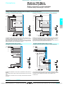
Dimensions, mounting
Front view
Mounting
c
108,3 (1)
a
140
17
AF1-AE4
b
132,5 (2)
J
(4)
G
H
152 (3)
TSX 37
a
05 028DR1
170.3
08 056DR1
227.9
10 028/128/164pp1
170.3
21/22 p01
227.9
(1) Empty PLC
(2) With screw terminal block
(3) With HE 10 type or SUB-D connectors
(4) Fixing holes for M4 screws
1
5,5
151
151
5,5
Side view
b
–
–
282.7
341.4
c
–
19
–
19
TSX 37
05 028DR1
08 056DR1
10 028/128/164pp1
21/22 p01
G
159.2
198.9
159.2
198.9
H
–
–
271.7
311.4
J
5
24
5
24
Mounting for TSX FAN ppP modules
32,5
58
54
110
138
140
146
150
Installation regulations
100
(1)
(3)
100
150
(1)
(1)
(3)
(1)
150
(1)
(1)
(2)
(1) u 50 mm
(2) Switch gear or enclosure
(3) Cable ducting or wiring clip
Description:
pages 1/2 to 1/7
Functions:
pages 1/8 and 1/9
Characteristics:
pages 1/13 and 1/14
References:
pages 1/15 and 1/16
1/17
Courtesy of Steven Engineering, Inc. ● 230 Ryan Way, South San Francisco, CA 94080-6370 ● General Inquiries: (800) 670-4183 ● www.stevenengineering.com
efesotomasyon - telemecanique inverter
0
2
2/0
Courtesy of Steven Engineering, Inc. ● 230 Ryan Way, South San Francisco, CA 94080-6370 ● General Inquiries: (800) 670-4183 ● www.stevenengineering.com
efesotomasyon - telemecanique inverter
Contents
2 - Discrete I/O
2.1 - Discrete I/O
Selection guide I/O modules . . . . . . . . . . . . . . . . . . . . . . . . . . . . . . . . . . page 2/2
b Discrete I/O modules . . . . . . . . . . . . . . . . . . . . . . . . . . . . . . . . . . . . . . . . page 2/6
b Safety module . . . . . . . . . . . . . . . . . . . . . . . . . . . . . . . . . . . . . . . . . . . . page 2/18
b Extension module for Nano PLCs . . . . . . . . . . . . . . . . . . . . . . . . . . . . . page 2/24
2.2 - Connection interfaces
2
Selection guide Telefast® 2 pre-wired system . . . . . . . . . . . . . . . . . . . page 2/26
b Telefast 2 pre-wired system
v Presentation, compatibility. . . . . . . . . . . . . . . . . . . . . . . . . . . . . . . . . page 2/32
v References . . . . . . . . . . . . . . . . . . . . . . . . . . . . . . . . . . . . . . . . . . . . page 2/34
v Accessories for connection sub-bases . . . . . . . . . . . . . . . . . . . . . . . page 2/40
v Dimensions . . . . . . . . . . . . . . . . . . . . . . . . . . . . . . . . . . . . . . . . . . . . page 2/42
b Installation system
v Tego Dial for Human-Machine interfaces . . . . . . . . . . . . . . . . . . . . . page 2/44
v Tego Power for motor power-starter components . . . . . . . . . . . . . . . page 2/46
v Compatibility Tego system/Modicon PLCs . . . . . . . . . . . . . . . . . . . . . . . . . . page 2/48
2.3 - Phaseo power supplies
Selection guide power supplies for DC control circuits . . . . . . . . . . . page 2/50
b Presentation . . . . . . . . . . . . . . . . . . . . . . . . . . . . . . . . . . . . . . . . . . . . . page 2/52
b Characteristics. . . . . . . . . . . . . . . . . . . . . . . . . . . . . . . . . . . . . . . . . . . . page 2/56
b References . . . . . . . . . . . . . . . . . . . . . . . . . . . . . . . . . . . . . . . . . . . . . . page 2/60
b Dimensions . . . . . . . . . . . . . . . . . . . . . . . . . . . . . . . . . . . . . . . . . . . . . . page 2/62
2/1
Courtesy of Steven Engineering, Inc. ● 230 Ryan Way, South San Francisco, CA 94080-6370 ● General Inquiries: (800) 670-4183 ● www.stevenengineering.com
efesotomasyon - telemecanique inverter
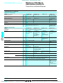
Selection guide
Modicon TSX Micro
automation platform
0
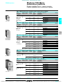
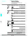
Discrete I/O modules
Applications with standard format modules
I/O connection on screw terminal block: via bare wires, via wires fitted with cable ends, or wires fitted with
Type
Nature
32 inputs
Inputs c 24 V
Connection
Connection via screw terminal block (supplied with the module)
2
2.1
32 outputs
Outputs c 24 V solid state
0.5 A
Outputs c/a relay 2A (Ith)
Possible association with Connection sub-base
Telefast 2 sub-base
I/O adaptor sub-base
Possible association
with Tego systems
Tego Dial
Tego Power
Isolated inputs
Control
Sensor voltage monitoring
IEC 1131-2 conformity
Logic
Prox.sens. compat. conforming
to standard IEC 947-5-2
Type 2
Positive
c 2-wire, c/a 2-wire,
c 3-wire PNP
Isolated outputs
Control
IEC 1131-2 conformity
Protection
Logic
Type of modules
TSX DEZ 32D2
Pages
2/13
Preactuator voltage
monitoring
Configurable fallback of
outputs
Yes
Protected
Positive
Configurable fallback of outputs
TSX DSZ 32T2
TSX DSZ 32R5
–
Non-protected
–
2/2
Courtesy of Steven Engineering, Inc. ● 230 Ryan Way, South San Francisco, CA 94080-6370 ● General Inquiries: (800) 670-4183 ● www.stevenengineering.com
efesotomasyon - telemecanique inverter
0
open or closed tags (minimum cross-section 0.2mm2, maximum 1.5 mm2)
I/O connection on HE 10 type connector: with preformed
cables with flying leads (cross-section 0.324 mm2), ribbon
cables (cross-section 0.08 mm2) or conection cables (crosssection 0.324 mm2).
2
2.1
16 inputs/12 outputs
Inputs c 24 V
Relay outputs 3 A (lth)
Inputs a 100…120 V
Relay outputs 3 A (lth)
32 inputs/32 outputs
Inputs c 24 V
Outputs c 24 V/0.1 A
Inputs c 24 V
Outputs c 24 V/0.5 A
Connection via 20-way HE 10 connector
8, 12 or 16 channels, with or without LED, with common or
terminals per channel
Inputs: 16 channels c 5 V TTL, c 24 V, c 48 V, a 48 V,
a 115 V or 230 V, 2 terminals per channel
Outputs: 8 or 16 channels, with 1 N/O, 1 or 2 C/O or solid state
relays, c 5…48 V, c 24 V, a 24…240 V 1 or 2 terminals
per channel
Yes (see page 2/44)
Yes (see page 2/46)
Sensor voltage monitoring
Type 1
Positive/Negative
c 2-wire,
c 3-wire PNP/NPN
Type 2
–
c/a 2-wire, a 2-wire
Type 1
Positive
c 2-wire,
c 3-wire PNP
Preactuator voltage monitoring
Configurable fallback of outputs
Yes
Protected
Positive
TSX DMZ 28DR
TSX DMZ 28AR
TSX DMZ 28DT
TSX DMZ 28DTK
TSX DMZ 64DTK
2/3
Courtesy of Steven Engineering, Inc. ● 230 Ryan Way, South San Francisco, CA 94080-6370 ● General Inquiries: (800) 670-4183 ● www.stevenengineering.com
efesotomasyon - telemecanique inverter
Selection guide (continued)
Modicon TSX Micro
automation platform
0
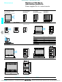
Discrete I/O modules
Applications for half-format modules
I/O connection on screw terminal block: via bare wires, via wires fitted with cable ends, or wires fitted with
maximum 1.5 mm2.
Type
Nature
12 inputs
Inputs c 24 V
Connection
Connection via screw terminal block (supplied with the module)
2
2.1
Possible association
with Telefast 2
8 inputs
Inputs
a 100…120 V
Inputs
a 200…240 V
8 outputs
Outputs
c/a relay 3 A (lth)
Connection sub-base
I/O adaptor sub-base
Possible association
with Tego systems
Tego Dial
Tego Power
Isolated inputs
Control
EC 1131-2 conformity
Logic
Prox.sens.compat. conforming
to standard IEC 947-5-2
Isolated outputs
Sensor voltage monitoring
Type 1
Type 2
Positive/negative
–
c 2-wire
c/a 2-wire,
c 3-wire PNP/NPN
a 2-wire
Type 1
a 2-wire
Control
Configurable
fallback of outputs
IEC 1131-2 conformity
Protection
Logic
–
Non-protected
–
Type of modules
TSX
DEZ 12D2
Pages
2/13
TSX
DEZ 08A4
TSX
DEZ 08A5
TSX
DSZ 08R5
2/4
Courtesy of Steven Engineering, Inc. ● 230 Ryan Way, South San Francisco, CA 94080-6370 ● General Inquiries: (800) 670-4183 ● www.stevenengineering.com
efesotomasyon - telemecanique inverter
0
open or closed tags (minimum cross-section 0.28 mm2),
I/O connection on HE 10 connector: with preformed cables with flying leads (cross-section
0.324 mm2) ribbon cables (cross-section 0.08 mm2) or connection cables (cross-section
0.324 mm2).
2
2.1
4 outputs
Outputs c 24 V/2 A
8 outputs
Outputs c 24 V/0.5 A
12 inputs
Inputs c 24 V
8 inputs/8 outputs
Inputs c 24 V
Outputs c 24 V/0.5 A
Connection via 20-way HE 10 connector
8, 12 or 16 channels, with or without DEL, with common or
2 terminals per channel
Inputs: 16 channels c 5 V TTL, c 24 V, c 48 V, a 48 V,
a 115 V or 230 V, 2 terminals per channel
Outputs: 8 or 16 channels with 1 N/O pr C/O pr spmod state
remaus, c 5…48 V, c 24 V, a 24…240 V 1 or 2 terminals
per channel
Yes (see page 2/44)
Yes (see page 2/46)
Sensor voltage monitoring
Type 2
Positive
c/a 2-wire, c 2-wire
c 3-wire PNP
Type 1
c 2-wire,
c 3-wire PNP
Preactuator voltage monitoring
Configurable fallback of outputs
Preactuator voltage
monitoring. Configurable
fallback of outputs
Yes
Protected
Positive
Yes
Protected
Positive
TSX DSZ 04T22
TSX DSZ 08T2
TSX DSZ 08T2K
TSX DEZ 12D2K
TSX DMZ 16DTK
2/5
Courtesy of Steven Engineering, Inc. ● 230 Ryan Way, South San Francisco, CA 94080-6370 ● General Inquiries: (800) 670-4183 ● www.stevenengineering.com
efesotomasyon - telemecanique inverter
Modicon TSX Micro
automation platform
Connection principles
0
Discrete I/O modules
Connection principles
Connecting modules with screw terminal blocks
The screw connection terminal blocks are fitted with a removable cover ensuring:
b The screws are held in place
b Personnel safety
Each terminal on a screw terminal block can accept bare wires or wires fitted with
cable ends, with closed or open tags. The capacity of each terminal is:
b Minimum:
v 1 wire 0.28 mm2 (AWG 23) without cable end
b Maximum:
v 2 wires 1 mm 2 (AWG 17) with cable end, or
v 1 wire 1.5 mm2 (AWG 15) without cable end, or
v 1 open or closed tag for wires of 1 mm2 (AWG 17).
2
2.1
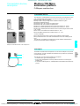
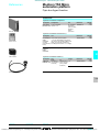
Connecting modules with HE 10 type connectors
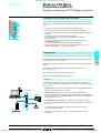
Prewired cable with 20 flying leads, gauge 22 (0.324 mm2)
1
Used for the simple and direct wire to wire connection of the
I/O of modules with connectors 1 to the sensors, preactuators or terminals.
The prewired cable 3 comprises:
At one end, a moulded HE 10 type connector 2 with 20 x 0.34 mm2 cross-section
wires in a sheath.
At the other end 4, flying leads -differentiated by colour coding conforming to DIN
47100.
2
3
TSX CDP 301: length 3 m,
TSX CDP 501: length 5 m,
TSX CDP 1001: length 10 m.
4
1
Sheathed rolled ribbon cable, gauge 28 (0.08 mm2)
4
3
Used to connect the I/O of modules with HE 10 type connectors 1 to Telefast 2
connection and adaption rapid wiring interfaces 2. The cable 3 comprises 2 HE 10
type connectors 4 and a sheathed rolled ribbon cable with 0.08 mm2 cross-section
wires.
Bearing in mind the small cross-section of the wire, this method of connection is only
recommended for low current I/O (100 mA maximum per input or per output).
TSX CDP 102: length 1 m,
TSX CDP 202: length 2 m,
TSX CDP 302: length 3 m.
Connection cable, gauge 22 (0.324 mm2)
Used to connect the I/O of modules with HE 10 type connectors 1 to Telefast 2
connection and adaption rapid wiring interfaces 2. The cable 5 comprises 2 moulded
HE 10 type connectors 6 and a cable suitable for carrying higher currents (500 mA
maximum).
6
TSX CDP 053: length 0.5 m,
TSX CDP 103: length 1 m,
TSX CDP 203: length 2 m,
TSX CDP 303: length 3 m,
TSX CDP 503: length 5 m,
TSX CDP 1003: length 10 m.
5
4
6
2
Characteristics:
pages 2/9 to 2/12
References:
pages 2/13 and 2/14
Connections :
Connections:
pages 2/15 to 2/17
2/6
Courtesy of Steven Engineering, Inc. ● 230 Ryan Way, South San Francisco, CA 94080-6370 ● General Inquiries: (800) 670-4183 ● www.stevenengineering.com
efesotomasyon - telemecanique inverter
Modicon TSX Micro
automation platform
Connection principles
(continued),
description
0
Discrete I/O modules
Connection principles (continued)
Connection to Tego Dial and Tego Power systems
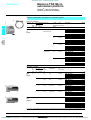
The TSX DMZ 16 DTK 1 module is also designed for association with Tego Dial and
Tego Power (1) systems set up.
In the example the connection is achieved by simply connecting cable TSX CDP pp3
2 to the APE-1B24M Dialbase sub-base 3 installed on the Dialpack console 4, which
is fitted with a mounting plate 5 for MMI components.
1
2
2.1
3
2
4
5
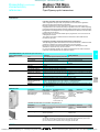
Description
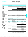
Discrete I/O modules connected via screw terminal block
Half-format or standard format I/O modules with connection via screw terminal block
comprise:
1
1 At rigid metal casing.
2 At locking mechanism for fixing the module in its slot. This can only be accessed
when the terminal block is removed.
3 At removable screw terminal block for connection to sensors and preactuators.
4 At cover for the terminal block screws, which also serves as a label holder.
2
3
4
Half-format or standard format I/O module
Discrete I/O modules connected via connector
I/O modules with connection via connector comprise:
1
1 At rigid metal casing.
2 At locking mechanism for fixing the module in its slot.
3 One, two or four HE 10 connectors for connection to sensors and preactuators.
1
2
2
3
3
Half-format I/O module
Standard format I/O module
Discrete I/O module connected via connector and cage terminal
The TSX DMZ 16DTK module comprises:
1
2
3
4
At rigid metal casing.
At locking mechanism for fixing the module in its slot.
One HE 10 connector for connection to sensors and preactuators.
At cage terminal for connecting the input and output power supplies.
(1) See pages 2/44 to 2/3.
Characteristics:
pages 2/9 to 2/12
References :
References:
pages 2/13 and 2/14
Connections:
pages 2/15 to 2/17
2/7
Courtesy of Steven Engineering, Inc. ● 230 Ryan Way, South San Francisco, CA 94080-6370 ● General Inquiries: (800) 670-4183 ● www.stevenengineering.com
efesotomasyon - telemecanique inverter
Modicon TSX Micro
automation platform
Functions,
compatibility
0
Discrete I/O modules
Functions
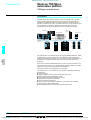
I/O assignment
By software configuration, specific functions can be assigned to certain inputs. The
first four inputs of a discrete I/O module located in slot 1 of a TSX Micro PLC can be
configured as discrete inputs, latching inputs, event-triggered inputs or up/down
counter inputs.
Inputs which can be configured as latching inputs
These are inputs %I1.0 to %I1.3. The principle is that, on a pulse which is shorter
than the PLC scan, the pulse is stored and processed on the next PLC scan. The
pulse is taken into account when the input changes state (rising and/or falling edge
depending on the selected configuration).
2
Inputs which can be configured as event-triggered inputs
These are inputs %I1.0 to %I1.3. On command events, the application program is
diverted directly to the event processing associated with the input causing the event.
The event is taken into account when the input changes state (rising and/or falling
edge depending on the selected configuration).
2.1
Inputs which can be configured as up/down counter inputs
These are inputs %I1.0 to %I1.3. Depending on the software configuration, these
inputs enable the creation of up to 2 up/down counter channels, each of which can
execute one of the following functions independently: upcounting function,
downcounting function, up/down counting with or without direction discrimination.
RUN/STOP command
Input %I1.8 can be set to control the RUN/STOP command on the PLC. This is taken
into account on a rising edge. At STOP command via an input has priority over the
RUN command via the terminal or network.
Program and data backup input
Input %I1.9 can be set to back up the application program in the Flash EPROM
memory (in the internal RAM) and the first 1000 words %MWi maximum on a rising
edge.
Alarm output
On a PLC base, output %Q2.0 can, after configuration, be assigned to the ALARM
function. When setting the PLC to RUN and if no blocking fault is detected, the alarm
output changes to state 1. It can be used in safety circuits external to the PLC, for
example to control the output preactuators power supply, or the TSX Micro PLC
power supply.
2/3-wire proximity sensor compatibility
Type of sensors
Types of inputs
c 24 V
Type 1
Positive logic
c 24 V
Type 2
Positive logic
c 24 V
a 100…120 V
Type 2
a 200…240 V
Type 1
Negative logic
All c 3-wire prox. sensors, PNP type
All c 3-wire prox. sensors, NPN type
c 2-wire proximity sensor, Telemecanique or other brand
having the following characteristics:
b Residual voltage, closed y 7 V
b Minimum switching capacity y 2.5 mA
b Residual current, open y 1.5 mA
c/a 2-wire proximity sensor
(1)
a 2-wire proximity sensor
(1)
Compatible
(1) In the nominal voltage range a 220…240 V.
Characteristics:
pages 2/9 to 2/12
References :
References:
pages 2/13 and 2/14
Connections:
pages 2/15 to 2/17
2/8
Courtesy of Steven Engineering, Inc. ● 230 Ryan Way, South San Francisco, CA 94080-6370 ● General Inquiries: (800) 670-4183 ● www.stevenengineering.com
efesotomasyon - telemecanique inverter
Modicon TSX Micro
automation platform
Characteristics
0
Discrete I/O modules
Characteristics of c 24 V input modules (1)
Type of modules
Number of inputs
Connection
Nominal input
values
TSX DEZ 12D2/TSX DMZ 28DR
12/16
Screw terminal block
Voltage
V
Current
Sensor supply (ripple included)
Input limit values At state1
Voltage
Current
At state 0
Voltage
Current
Input impedance at state 1
Configurable
State 0 to 1
response time
State 1 to 0
IEC 1131-2 conformity
Proximity sensor compatibility 2/3-wire
Isolation resistance
Type of input
Consumption
Dissipated power
mA
Isolation
V rms
V rms
Between channels and ground
Between channels and internal logic
V
mA
V
mA
KΩ
ms
ms
MΩ
W
Type of modules
Number of inputs
Connection
Nominal input
values
Voltage
Current
Sensor supply (ripple included)
Input limit values At state1
Voltage
Current
At state 0
Voltage
Current
Input impedance at state 1
Configurable
State 0 to 1
response time
State 1 to 0
EC 1131-2 conformity
Proximity sensor compatibility 2/3-wire
Isolation resistance
Type of input
Consumption
Dissipated power
Isolation
Between channels and ground
Between channels and internal logic
References:
pages 2/13 and 2/14
Connections :
V
mA
V
mA
V
mA
KΩ
ms
ms
MΩ
W
V rms
V rms
TSX DEZ 12D2K/TSX DEZ 32D2
12/32
HE 10 connector/screw terminal
block
TSX DMZ 16DTK
8
HE 10 connector/
enclosed terminal
block
c 24 (positive
c 24 (negative
c 24 (positive logic)
logic)
logic )
9
6
7
19…30 (possible up to 34 V, limited to 1 hour per 24 hours)
u 11
y8
u 11
> 2.5
>6
> 2.5
<5
> Ual - 5
<5
< 1,5
<2
< 1.5
2.4
4
3,4
0.1…7.5
0.1…7.5
Yes, type 1
–
Yes, type 2
Yes, type 1
Yes
> 10 at c 500 V
Resistive
Current sink
Resistive
See page 6/4
TSX DEZ 12D2: 2,7
TSX DEZ 12D2K: 2,7
3
TSX DMZ 28DR: 4.5
TSX DEZ 32D2: 6
1500 - 50/60 Hz for 1 minute
1500 - 50/60 Hz for1 minute
TSX DMZ 28DTK/DMZ 28DT
TSX DMZ 64DTK
TSX ACZ 03 (3)
16
32
8
HE 10 connector/screw terminal
HE 10 connector
SUB- D connector
block
c 24 (positive logic)
7
3.5
8
19…30 (possible up to 34 V, limited to 1 hour per 24 hours)
u 11
> 2.5
<5
<5
<5
< 1.5
< 1.4
< 1.4
3.4
6.3
2.67
0.1…7.5
1/1.5 (fixe)
0.1…7.5
0.2/0.3 (fixe)
Yes, type 1
Yes
> 10 at c 500 V
Resistive
Current sink
Resistive
See page 6/4
5
–
1500 - 50/60 Hz for 1 minute
–
1500 - 50/60 Hz for 1 minute
–
(1) Characteristics at 60 °C for 60 % I/O loading or at 30 °C for 100 % I/O loading.
(2) Adaptation and analogue adjustment module enables the transformation of 8 integral
analogue inputs for TSX 37 22 bases into 8 discrete inputs (see page 3/4).
2
2.1
Connections:
pages 2/15 to 2/17
2/9
Courtesy of Steven Engineering, Inc. ● 230 Ryan Way, South San Francisco, CA 94080-6370 ● General Inquiries: (800) 670-4183 ● www.stevenengineering.com
efesotomasyon - telemecanique inverter
Modicon TSX Micro
automation platform
Characteristics (continued)
0
Discrete I/O modules
Characteristics of a.c. input modules (1)
Type of modules
Number of inputs
TSX DEZ 08A4
8
Connection
Screw terminal block
Nominal input
values
a 100…120
a 200…240
a 100…120
50 Hz
mA
11
10
11
60 Hz
mA
13
12
13
Frequency
Hz
47…63
Sensor supply
V
85…132
170…264
85…132
Voltage
V
u 74
u 120
u 74
Current
mA
u 6 (for U = 74 V)
u 6 (for U = 164 V)
u 6 (for U = 74 V)
Voltage
V
< 20
< 40
< 20
Current
mA
<4
<5
<4
50 Hz
ms
11…18
60 Hz
ms
9…16
50 Hz
ms
11…24
60 Hz
ms
10…22
Yes, type 1
Yes, type 2
1.4
5.6
2
Input limit values At state 1
At state 0
Response time
State 0 to 1
State 1 to 0
IEC 1131-2 conformity
Yes, type 2
Proximity sensor compatibility 2-wire
Yes
Isolation resistance
MΩ
> 10 at c 500 V
Type of input
Capacitive
Consumption
See page 6/4
Dissipated power
Isolation
TSX DMZ 28AR
16
V
Voltage
Current
2.1
TSX DEZ 08A5
W
1.7
Between channels and ground
V rms
2000 - 50/60 Hz for 1 minute
Between channels and internal logic
V rms
2000 - 50/60 Hz for 1 minute
(1) Characteristics at 60 °C for 60 % I/O loading or at 30 °C for 100 % I/O loading.
References:
pages 2/13 and 2/14
Connections :
Connections:
pages 2/15 to 2/17
2/10
Courtesy of Steven Engineering, Inc. ● 230 Ryan Way, South San Francisco, CA 94080-6370 ● General Inquiries: (800) 670-4183 ● www.stevenengineering.com
efesotomasyon - telemecanique inverter
Modicon TSX Micro
automation platform
Characteristics (continued)
0
Discrete I/O modules
Characteristics of solid state output modules
(1)
Type of modules
Number of outputs
Connection
Nominal output values
TSX DSZ 08T2K
DMZ 28DTK DSZ 08T2
DMZ 28 DT
DSZ 32T2
8
12
8
12
32
HE 10 connector
Screw terminal block
Voltage
V
c 24
Current
A
0.5
Tungsten filament lamp
W
10
Limit output values
Voltage
V
19…30 (possible up to 34 V, limited at 1 hour per 24 hours)
Current (for U = 30 ou 34 V) A
0.625
Logic
Positive, current source
Leakage current at state 0
mA
< 0.5 (< 2 for accidental disconnection of the 0 V module)
Residual voltage
V
< 0.3 (for I = 0.5 A)
Minimum load impedance
Ω
48
Response time
From state 1
ms
< 0.5
(2)
From state 0
ms
< 0.5
Switching frequency on inductive load
Hz
< 0.6/LI2
Built-in protection
Against overvoltages
By Zener diode
Against reverse polarity
By reverse mounted diode on power supply. Provide 1 fast-blow fuse on the + c 24 V of the
preactuator supply.
Against short-circuits and
A
By current limiter and thermal breaker
overloads
0.75 y Id y 2
Paralleling of outputs
2 outputs max.
Consumption
See page 6/4
Nominal dissipated power Via module
W
3.5
3.2
Via channel at 1
W
0.15
Isolation(test voltage)
Between output and ground V rms 1500 - 50/60 Hz for 1 minute
Between outputs and
V rms 1500 - 50/60 Hz for 1 minute
internal logic
Insulation resistance
MΩ
> 10 at c 500 V
Type of modules
Nombre of sorties
Connection
Nominal output values
Limit output values
TSX DSZ 04T22
4
Screw terminal block
Voltage
Current
Tungsten filament lamp
Voltage
Current (for U = 30 ou 34 V)
Logic
Leakage current at state 0
mA
Residual voltage
Minimum load impedance
Response time
From state 1
(2)
From state 0
Switching frequency on inductive load
Built-in protection
Against overvoltages
Against reverse polarity
Against short-circuits and
overloads
Paralleling of outputs
Consumption
Nominal dissipated power Via module
Via channel at 1
Isolation(test voltage)
Between output and ground
Between outputs and
internal logic
Insulation resistance
References:
pages 2/13 and 2/14
Connections :
V
A
W
V
A
V
Ω
ms
ms
Hz
A
W
W
V rms
V rms
MΩ
TSX DMZ 16DTK
8
HE 10 connector, cage
terminal block
2
2.1
TSX DMZ 64DTK
32
HE 10 connector
c 24
2
0.5
0.1
15
10
1.2 max.
19…30 (possible up to 34 V, limited at 1 hour per 24 hours)
2.5
0.625
0.25
Positive, current emis
< 0.5
< 0.5 ( < 2 for accidental
< 0.1
disconnection of the 0 V
module)
< 0.8 (for I = 2 A)
< 0.3 (for I = 500 mA)
< 1.5
12
48
220
<1
< 0.5
< 0.25
<1
< 0.5
< 0.25
< 0.5/LI2
< 0.6/LI.
< 0.5/LI
By Zener diode
By reverse mounted diode on power supply. Provide 1 fast-blow fuse on the + c 24 V of the
preactuator supply.
By current limiter and
By current limiter and thermal By current limiter and
elecctronic breaker
breaker
elecctronic breaker
2.6 y Id y 5
0.75 y Id y 2
0.125 y Id y 0.185
2 outputs max.
3 outputs max.
See page 6/4
3.8
3
3.5
1.15 (U = 24 V)
0.15
< 0.7 (U = 24 V)
1500 - 50/60 Hz for 1 minute
1500 - 50/60 Hz for 1 minute
> 10 at c 500 V
(1) Characteristics at 60 °C for 60 % I/O loading or at 30 °C for 100 % I/O loading.
(2) All outputs have fast demagnetisation circuits for electro-magnets. Discharge time of
electro-magnets < L/R.
Connections:
pages 2/15 to 2/17
2/11
Courtesy of Steven Engineering, Inc. ● 230 Ryan Way, South San Francisco, CA 94080-6370 ● General Inquiries: (800) 670-4183 ● www.stevenengineering.com
efesotomasyon - telemecanique inverter
Modicon TSX Micro
automation platform
Characteristics (continued)
0
Discrete I/O modules
Characteristics of relay outputs (connection via screw terminal block) (1)
Type of modules
TSX DSZ
08R5
8
Number of outputs
a
c
Operating limit values
V
V
Type of contact
2
Response time
Built-in
protection
32
19…264
10…34
A
3 (5 A max. per common of each group of
channels)
2 ( 7 A max. per common of each group of 16
channels
Voltage
Power
V
VA
24
50 (8)
48
50 (10)
110 (7)
110
110 (10)
220 (7)
220
220 (10)
24
50 (6)
48
100 (5)
110…120 200…240
200 (4)
200 (6)
Inductive AC - 14 Voltage
and AC - 15
Power
V
VA
24
24 (7)
48
10 (15)
24 (13)
110
10 (16)
50 (12)
110 (3)
220
10 (16)
50 (14)
110 (10),
220 (2)
24
24 (2)
48
50 (2)
110…120 200…240
10 (9)
10 (11)
50 (3)
50 (5)
Resistive DC-12
Voltage
Power
V
W
24
24 (1 x 10⁶ cycles of operations)
40 (0.3 x 10⁶ cycles of operations)
24
12 (0.5 x 10⁶ cycles of operations)
24 (0.3 x 10⁶ cycles of operations)
48 (0.15 x 10⁶ cycles of operations)
Inductive DC - 13 Voltage
(L/R = 60 ms)
Power
V
W
24
10 (2 x 10⁶ cycles of operations)
24 (1 x 10⁶ cycles of operations)
24
6 (0.12 x 10⁶ cycles of operations)
12 (0.06 x 10⁶ cycles of operations)
24 (0.03 x 10⁶ cycles of operations)
Activation
ms
< 10
Desactivation
ms
< 10
Resistive AC-12
2.1
d.c. load
TSX DSZ 32R5
NO
Thermal current
a.c. load
TSX DMZ TSX DMZ 28AR
28DR
12
12
Against short-circuits and overloads
None, obligatory mounting of a fast blow fuse per channels or groups of channels
Against inductive overvoltages in a
None, obligatory parallel mounting of a RC circuit or an MOV (ZNO) peak limiter appropriate to
the voltage
None, obligatory mounting of a flywheel diode on the terminals of each preactuator
See page 6/4
Against inductive overvoltages in c
Consumption
Type of modules
Dissipated power per module
W
TSX DSZ
08R5
1.5
Isolation (test
voltage)
V rms
V rms
MΩ
2000 - 50/60 Hz for 1 minute
2000 - 50/60 Hz for 1 minute
> 10 at c 500 V
Between outputs and ground
Between outputs and internal logic
Insulation resistance
TSX DMZ TSX DMZ 28AR
28DR
4.5
5.6
TSX DSZ 32R5
3.5
(1) Characteristics at 60 °C for 60 % I/O loading or at 30 °C for 100 % I/O loading.
(2) For 0.1 x 10⁶ operations.
(3) For 0.15 x 10⁶ operations.
(4) For 0.2 x 10⁶ operations.
(5) For 0.25 x 10⁶ operations.
(6) For 0.3 x 10⁶ operations.
(7) For 0.5 x 10⁶ operations.
(8) For 0.7 x 10⁶ operations.
(9) For 0.8 x 10⁶ operations.
(10) For 1 x 10⁶ operations.
(11) For 1.2 x 10⁶ operations.
(12) For 1.5 x 10⁶ operations.
(13) For 2 x 10⁶ operations.
(14) For 3 x 10⁶ operations.
(15) For 5 x 10⁶ operations.
(16) For 10 x 106 operations.
References:
pages 2/13 and 2/14
Connections :
Connections:
pages 2/15 to 2/17
2/12
Courtesy of Steven Engineering, Inc. ● 230 Ryan Way, South San Francisco, CA 94080-6370 ● General Inquiries: (800) 670-4183 ● www.stevenengineering.com
efesotomasyon - telemecanique inverter
Modicon TSX Micro
automation platform
References
0
Discrete I/O modules
References
Discrete input modules
Nature of current
c
Input voltage
24 V (positive
logic
IEC type 2)
Modularity
(no.of
channels)
12
Format
Connection
Reference
Weight
kg
Half
0.160
32
Standard
Via HE 10 type
TSX DEZ 12D2K
connector
(1)
Via screw terminal TSX DEZ 32D2
block (supplied)
0.290
2
24 V ((positive 12
logic IEC type 1
or (negative
logic)
Half
Via screw terminal TSX DEZ 12D2
block (supplied)
0.230
100…120 V
IEC type 2
8
Half
Via screw terminal TSX DEZ 08A4
block (supplied)
0.230
200…240 V
IEC type 1
8
Half
Via screw terminal TSX DEZ 08A5
block (supplied)
0.230
Format
Connection
Reference
Half
Via HE 10 type
connector (1)
TSX DSZ 08T2K
TSX DEZ 12D2
a
2.1
Discrete output modules
Nature of current
c
solid state protected
TSX DSZ 08T2K
c/a
relay, not protected
Output voltage Modularity
(no.of
channels)
24 V/0.5 A
8
protected
Weight
kg
0.180
Via screw terminal TSX DSZ 08T2
block (supplied)
0.240
32
Standard
Via screw terminal TSX DSZ 32T2
block (supplied)
0.420
24 V/2 A
protected
4
Half
Via screw terminal TSX DSZ 04T22
block (supplied)
0.310
c 24 V
or
a 24…240 V
8
Half
Via screw terminal TSX DSZ 08R5
block (supplied)
0.260
32
Standard
Via screw terminal TSX DSZ 32R5
block (supplied)
0.580
Discrete I/O modules
Nombre d’E/S
16
28
TSX DMZ 16DTK
Number, type
of inputs
8, c 24 V
(positive logic
IEC type 1)
Number, type Format
of outputs
8, solid state Half
c 24 V/0.5 A
protected
Connection
16, c 24 V
(positive logic
IEC type 1)
12, solid state Standard
c 24 V/0.5 A
protected
Via HE 10 type
connector (1)
TSX DMZ 28DT TSX DMZ 64DTK
Characteristics:
pages 2/9 to 2/12
Via HE 10 type
TSX DMZ 16 DTK
connector (1) and
enclosed terminal
block
TSX DMZ 28DTK
Weight
kg
0.160
0.330
Via screw terminal TSX DMZ 28DT
block (supplied)
0.465
12, relay
Standard
50 VA
not protected
Via screw terminal TSX DMZ 28DR
block (supplied)
0.500
16
12, relay
Standard
a 100…120 V 50 VA
IEC type 2
not protected
Via screw terminal TSX DMZ 28AR
block (supplied)
0.500
32, c 24 V
(positive logic
IEC type 1)
Via HE 10 type
connector (1)
0.410
16, c 24 V
(positive logic
IEC type 1 or
negative logic
64
Reference
32, solid state Standard
c 24 V/0.1 A
protected
TSX DMZ 64DTK
(1) Module supplied with HE 10 type connector cover.
Connections:
pages 2/15 to 2/17
2/13
Courtesy of Steven Engineering, Inc. ● 230 Ryan Way, South San Francisco, CA 94080-6370 ● General Inquiries: (800) 670-4183 ● www.stevenengineering.com
efesotomasyon - telemecanique inverter
References (continued)
Modicon TSX Micro
automation platform
0
Discrete I/O modules
References
(continued)
Connecting cables for I/O modules fitted with HE 10 type connectors
Description
Constitution Section
Use
20-wire
1 HE 10 type
0.324 mm2
preformed
connector,
cable
moulded
(500 mA max.) 1 end free with
wires identified
2
Length
Reference
3m
TSX CDP 301
Weight
kg
0.405
5m
TSX CDP 501
0.720
10 m
TSX CDP 1001
1.210
1m
TSX CDP 102
0.090
2m
TSX CDP 202
0.170
3m
TSX CDP 302
0.250
0.5 m
TSX CDP 053
0.085
1m
TSX CDP 103
0.150
2m
TSX CDP 203
0.280
3m
TSX CDP 303
0.410
5m
TSX CDP 503
0.670
10 m
TSX CDP 1003
1.230
TSX CDP pp1
Preformed
connection
cables
(100 mA max.)
2.1
2 HE 10 type
0.08 mm2
connectors for
Telefast 2
system
Connecting
2 HE 10 type
cables
connectors,
(500 mA max.) moulded, for
Telefast 2,
Tego Dial et
Tego Power
systems
TSX CDP pp2
0.324 mm2
Simulator sub-base for I/O modules fitted with HE 10 type connectors
Description
TSX CDP pp3
2 01
2 01
0
1
2
3
4
5
6
7
Telefast 2
16-channel simulator
sub-base for discrete
inputs/outputs
8
9
10
11
12
13
14
15
Use
Reference
ABE 7TES160
Has 2 HE 10 type connectors
which enable it to be inserted
between the PLC I/O module
and the ABE 7H/P/R/S Telefast 2
I/O sub-base.
Used for display, forcing,
inhibition or continuity of discrete
I/O
Weight
kg
0.350
Replacement parts
ABE 7TES160
Description
Use
Screw terminal blocks
For half-format modules
(supplied with I/O modules with
screw terminal block connection)
For standard format modules
TSX BLZ H01
TSX BLZ L01
Characteristics:
pages 2/9 to 2/12
Connections:
pages 2/15 to 2/17
Reference
TSX BLZ H01
Weight
kg
0.055
TSX BLZ L01
0.115
2/14
Courtesy of Steven Engineering, Inc. ● 230 Ryan Way, South San Francisco, CA 94080-6370 ● General Inquiries: (800) 670-4183 ● www.stevenengineering.com
efesotomasyon - telemecanique inverter
Modicon TSX Micro
automation platform
Connections
0
Discrete I/O modules
Connections
TSX DEZ 12D2K
TSX DEZ 12D2
Positive logic
Positive logic
Inputs
A
Inputs
Sensors
0
1
2
3
3
4
5
6
7
8
5
6
8
9
10
11
12
9
10
13
13
13
(1)
14
24 V
14
(1)
14
15
15
15
16
17
18
19
20
11
12
11
12
10
11
10
11
11
2.1
9
10
9
10
8
9
8
9
7
8
7
8
5
6
7
6
7
7
2
4
6
5
6
3
4
5
4
5
2
3
3
4
4
1
2
2
3
0
1
1
2
2
Inputs
Sensors
0
1
Sensors
1
Negative logic
24 V
(1)
24 V
TSX DEZ 32D2
TSX DSZ 32T2
Sensors
Outputs
1
0
1
2
3
2
3
4
5
4
5
6
7
6
7
8
9
8
9
10
11
10
11
12
13
12
13
14
15
14
16
15
Preactuators
0
1
3
21
1
2
22
23
3
24
25
4
5
26
27
6
7
8
28
29
9
30
10
11
31
12
32
33
13
34
35
FU1
14
15
1
4
6
7
7
8
10
11
11
13
14
+ 24 V
14
FU2 (2)
+ 24 V
0
1
16
FU1
18
(3)
FU2
17
19
20
3
7
27
9
29
6
8
13
33
12
6
7
15
35
26
27
9
10
28
29
11
12
30
31
13
14
34
24
25
8
32
14
22
23
5
30
31
21
4
28
11
20
3
26
10
18
19
1
24
25
16
0
2
23
5
15
17
22
4
14
15
(3)
21
2
12
13
13
15
15
11
12
13
14
10
11
12
12
8
9
9
10
10
6
7
7
8
9
9
4
5
5
6
8
2
3
3
4
6
Outputs
1
2
5
5
– +
0
0
2
FU1 (2)
20
Preactuators
3
4
18
19
Outputs
1
2
– +
17
TSX DSZ 32R5
FU3
(3)
32
33
15
34
35
–
+
(1) 0.5 A fast blow fuse
(2) 10 A fast blow fuse
(3) Fast blow fuses, rated according to the load
Characteristics:
pages 2/9 to 2/12
References:
pages 2/13 and 2/14
2/15
Courtesy of Steven Engineering, Inc. ● 230 Ryan Way, South San Francisco, CA 94080-6370 ● General Inquiries: (800) 670-4183 ● www.stevenengineering.com
efesotomasyon - telemecanique inverter
Connections (continued)
Modicon TSX Micro
automation platform
0
Discrete I/O modules
TSX DEZ 08A4/08A5
TSX DSZ 08T2K
TSX DSZ 08T2
Inputs
Sensors
0
1
2
3
4
4
3
4
5
5
6
5
6
5
6
6
7
8
2
3
4
5
6
1
3
4
7
2
2
3
4
Outputs
1
1
2
5
Preactuators
0
Preactuators
1
2
3
2
Outputs
0
1
6
7
8
7
7
8
7
9
9
10
9
10
10
11
2.1
11
12
12
11
24 V
13
12
(2)
13
(1)
14
14
13
14
15
15
24 V
TSX DEZ 28DTK
(2)
15
16
17
18
19
20
TSX DMZ 28DT
TSX DMZ 28DR
Positive logic (Sink)
A
Sensors
0
1
Sensors
Inputs
Inputs
Sensors
Inputs
1
2
3
3
4
5
6
7
6
7
8
9
10
11
12
13
14
15
16
17
18
19
20
9
9
11
11
10
8
14
14
16
(1)
(1)
B
0
1
1
2
3
4
5
6
7
8
(3)
20
0
20
21
21
2
18
24 V
19
19
0
15
17
18
24 V
14
16
15
17
(1)
13
14
15
15
15
12
13
13
14
11
12
11
12
13
10
11
10
12
13
9
10
9
10
12
24 V
7
8
7
8
8
9
5
6
5
6
7
8
4
5
6
7
3
4
3
4
5
5
6
2
3
2
4
4
1
2
1
2
2
3
0
1
0
1
1
22
2
22
23
1
3
2
23
4
3
(3)
24
5
4
25
6
5
7
6
8
9
10
28
11
12
24 V
24 V
14
15
17
16
Preactuators
Outputs
19
29
28
32
10
31
9
34
Outputs
(3)
32
33
11
34
35
Outputs
19É240 V
24 V
Preactuators
Negative logic (Source):
+ 24 V = terminal 17
- 24 V = terminal 18 = common
(1) 0.5 A fast blow fuse
(2) 10 A fast blow fuse
(3) Fast blow fuses, rated according to the load
20
Preactuators
Characteristics:
pages 2/9 to 2/12
8
35
18
7
30
30
33
(2)
(2)
(3)
31
11
13
27
29
10
11
26
5
6
27
9
10
9
4
26
8
7
24
25
3
References:
pages 2/13 and 2/14
2/16
Courtesy of Steven Engineering, Inc. ● 230 Ryan Way, South San Francisco, CA 94080-6370 ● General Inquiries: (800) 670-4183 ● www.stevenengineering.com
efesotomasyon - telemecanique inverter
Modicon TSX Micro
automation platform
Connections (continued)
0
Discrete I/O modules
Connections (continued)
TSX DSZ 04T22
TSX DSZ 08R5
Preactuators
Outputs
0
Preactuators
1
(2)
1
TSX DMZ 16DTK
0
1
1
3
Outputs
(2)
2
3
5
5
6
(2)
3
7
4
9
Sensors
10
10
5
11
5
6
Inputs
6
8
8
9
3
4
4
6
7
7
8
9
10
11
12
13
14
15
16
17
18
19
20
7
Outputs
11
Preactuators
2
2.1
12
12
(1)
1
2
4
4
5
24 V
1
2
3
3
0
2
2
2
Inputs
Sensors
13
6
(2)
13
(3)
14
14
7
15
15
24 V
(4)
19…240 V
24 V
TSX DMZ 28AR
24 V
TSX DMZ 64DTK
Sensors
Inputs
0
1
2
A1/A0
Inputs
Sensors
1
1
2
3
3
4
5
5
6
7
7
8
9
9
10
11
11
12
13
13
14
15
15
16
17
18
19
20
2
3
4
4
5
6
6
7
8
8
9
10
10
11
12
12
13
14
14
15
16
17
(3)
110 V
18
(3)
19
(2)
0
20
24 V
21
1
2
22
B1/B0
23
3
(2)
24
1
2
26
3
4
28
5
6
30
7
8
32
9
10
11
12
13
14
15
16
17
18
19
20
25
4
5
27
7
29
6
(2)
8
31
9
10
(2)
N° of channels
A1
A0
16
0
17
1
18
2
19
3
20
4
21
5
22
6
23
7
24
8
25
9
26
10
27
11
28
12
29
13
30
14
31
15
33
11
34
35
Outputs
19…240 V
24 V
Preactuators
24 V
(5)
Outputs
N° of channels
B1
B0
16
0
17
1
18
2
19
3
20
4
21
5
22
6
23
7
24
8
25
9
26
10
27
11
28
12
29
13
30
14
31
15
(1) 0.5 A fast blow fuse
(2) Fast blow fuses, rated according to the load
(3) 0.5 A fast blow fuse
(4) 6.3 A fast blow fuse
(5) 2 A fast blow fuse
20-wire preformed cable
TSX DEZ/DSZ/DMZ ppppK
Correspondence between HE 10 connector pin and
colour of wire
1
2
3
4
5
6
7
8
9
10
white
brown
green
yellow
grey
pink
blue
red
black
purple
11
12
13
14
15
16
17
18
19
20
grey/pink
red/blue
white/green
brown/green
white/yellow
yellow/brown
white/grey
grey/brown
white/pink
pink/brown
Preactuators
Characteristics:
pages 2/9 to 2/12
References:
pages 2/13 and 2/14
2/17
Courtesy of Steven Engineering, Inc. ● 230 Ryan Way, South San Francisco, CA 94080-6370 ● General Inquiries: (800) 670-4183 ● www.stevenengineering.com
efesotomasyon - telemecanique inverter
Modicon TSX Micro
automation platform
Presentation
0
Use of Preventa safety modules
Safety
Production workshops and technical building installations are subject to increasing requirements in terms of machine
safety
2
2.1
A good machine is a safe machine, combining:
b Safety of personnel (machine is not dangerous).
b Availability of the production tool (machine operational at any time).
b Safety is achieved by:
v simultaneously optimising safety and availability,
v using basic principles: redundancy, self-monitoring, etc,
v considering reliability (failure determining the behavior of the machine in a specified position, positive safety
features),
v ease of maintenance.
The machinery directive and the work equipment directive
The machinery directive
A machine manufacturer is required to conform to the machinery directive. The machinery directive
(89/392/EEC, 91/36/EEC, 93/44/EEC and 93/68/EEC) is designed to ensure the free circulation of machinery
and safety components in European Union countries and to improve the level of safety for personnel.
Harmonised European standards establish technical specifications which comply with the minimum safety
requirements defined in the corresponding directive.
Manufacturers must produce machinery which conforms to safety requirements.
The work equipment directive
The user is required to ensure that his range of machines conforms to the use of work equipment by
workers at work directive. Directive 89/655/EEC lays down the minimum objectives for protection in the
working environment and in particular concerns the use of products. The directive specifies the general
framework of preventative measures which should be taken in the workplace.
Safety and automated systems
All dangerous areas must be identified and have restricted access, controlled in a secure manner, ie. any
breakdown or careless operation must leave the automated system in a safe position.
It should be noted that the use of safety products does not necessarily mean that the machine conforms to the
machinery directive.
It is the operation, wiring, compatibility and scheme used, which make the entire machine safe. It is more important
to think in terms of safety solutions rather than safety products.
Groupe Schneider, safety specialists
Groupe Schneider, specialists in safety, has a range of several thousand products, all concerned directly or
indirectly with safety. Some of these products are exclusively designed for safety.
Preventa safety module
“Mushroom head”
emergency stop
button
Two-handel control
Safety module integrated in PLC
For further details on components for safety applications, please consult our specialist catalogue.
2/18
Courtesy of Steven Engineering, Inc. ● 230 Ryan Way, South San Francisco, CA 94080-6370 ● General Inquiries: (800) 670-4183 ● www.stevenengineering.com
efesotomasyon - telemecanique inverter
Modicon TSX Micro
automation platform
Presentation (continued)
0
Use of Preventa safety modules
Non-controlled safety systems
The control signal from the protection device (emergency stop pushbutton illustrated
to the left) acts directly on the power contactor of the machine.
In this type of scheme, the risks of simple faults are:
b emergency stop button being shorted.
b KM1 contactor sticking.
When the operator presses an emergency stop button, the instruction is not
processed, and another sequence can begin following the emergency stop, despite
the presence of the fault.
KM1
KM1
In the case of failure, the safety function (1) is compromised. Therefore, a reliable
intermediate relay system must be used.
(1) A safety function is a function whose non-execution or untimely execution results in the
immediate placement of the equipment into a non-hazardous position.
KM1
2
2.1
M
Safety system controlled by a Preventa safety module
Feedback loop
KM6
KM5
Emergency stop
Preventa safety module
KM5
KM5
KM6
KM6
Run
Redundancy
KM6
KM5
KM5 and KM6 contactors with mechnically linked contacts
M
Independent safety circuits
Preventa safety modules provide a reliable interposing relay function by eliminating
the risks of:
b A control circuit fault (inputs).
b A power circuit fault (outputs).
b A fault on an internal safety module component.
The safety function remains operative whenever any one of these faults
occur.
For the use of mechanically linked contacts CA2-DN22/DN31, LC1-D09/D18/D25,
LP1-D09/D18/D25 with contacts which can be used in the feedback loop, please
consult your Regional Sales Office.
2/19
Courtesy of Steven Engineering, Inc. ● 230 Ryan Way, South San Francisco, CA 94080-6370 ● General Inquiries: (800) 670-4183 ● www.stevenengineering.com
efesotomasyon - telemecanique inverter
Modicon TSX Micro
automation platform
Presentation,
description
0
Safety automation system solutions
Preventa safety module type TSX DPZ
Presentation
The TSX DPZ 10D2A Emergency stop monitoring module integrated into the
TSX Micro PLC combines:
b The ease of use of Preventa safety modules.
b PLC diagnostics performance.
It also maintains all the advantages of a standard PLC (extended choice of I/O, ease
of installation, flexibility of hardware and software developments, etc).
TSX Micro
2
The TSX DPZ 10D2A Emergency stop monitoring module combines a Preventa
(XPS) hard-wired safety relay and a discrete acquisition function in a half-slot, for full
diagnostics of input contacts and the state of safety circuit outputs.
Safety
relay
2.1
K4
The TSX DPZ 10D2A safety module is used to interrupt one or more Emergency or
safety stop control circuits in complete safety, in accordance with EN 60204-1.
The proven safety of hard-wired technology and the capacity of the TSX Micro PLC
make module TSX DPZ 10D2A the optimum solution for making machines more
reliable, safer, more compact and more cost-effective.
K3
Solution with safety relay and separate PLC
Application developments requiring safety systems and PLC diagnostics
LModule TSX DPZ 10D2A is suitable for Emergency stop and limit switch monitoring
applications, requiring a level of safety up to category 3 (1) according to EN 954-1
(safety related parts of control systems).
(1) For more information on control system safety categories, please consult our specialist
catalogue “Preventa safety solutions”.
TSX Micro + TSX DPZ
K4
K3
Simplification using the safety module integrated in the PLC
Description
Emergency stop monitoring module TSX DPZ 10D2A comprises:
1
1 A metal casing with a locking system for fixing the module in its slot. This system
is only accessible when the screw terminal block is removed.
2
2 A removable screw terminal block for connecting sensors and preactuators.
3
Characteristics:
page 2/22
3 A cover giving access to the screw terminal block, which also holds the marker
legend.
References:
page 2/22
Connections:
page 2/23
2/20
Courtesy of Steven Engineering, Inc. ● 230 Ryan Way, South San Francisco, CA 94080-6370 ● General Inquiries: (800) 670-4183 ● www.stevenengineering.com
efesotomasyon - telemecanique inverter
Modicon TSX Micro
automation platform
Functions
0
Safety automation system solutions
Preventa safety module type TSX DPZ
Safety module TSX DPZ 10D2A provides the following functions:
b Monitoring of 1 to 4 dual (or single), N/C (normally closed) contacts in pushbuttons, Emergency stops or limit
switches on safety guards for an Emergency stop or immediate safety stop system (category 0 Emergency stop
conforming to EN 418).
b Hard-wired safety module identical to Preventa safety module XPS:
v 2 N/O safety output circuits,
v category 3.
b Safety module independent of the TSX Micro PLC processor: the PLC does not affect the safety module.
b 10 LEDs on the TSX Micro PLC display panel: power supply failure and full diagnostics of the safety system.
b Electronic data acquisition units for full diagnostics of the safety system:
v reading the state of the 8 pushbutton or limit switch inputs,
v reading the enable input and the feedback loop,
v reading the control signal of the 2 safety outputs,
v monitoring the external power supply for the module.
This electronic data acquisition is designed so that the first failure will not adversely affect the safety function.
If the safety system uses more sensors, it is possible to daisy-chain several TSX DPZ 10D2A modules.
2
2.1
Schematic diagram
To ensure correct operation of the safety function whatever the first failure, the following must be used :
b At the inputs: Emergency stop pushbuttons or safety limit switches with dual contacts.
b At the outputs: if relaying is required, use relays with guided contacts.
b Module power supply: use an F1 protection fuse (see characteristics on page 2/22).
F1
14
S4
12
S5
10
S6
8
S7
TSX DPZ 10D2A
Ix,4
Ix,5
Ix,6
Ix,7
6
Ix,9
K1
ESC
5
K2 K1
4
7
S3
K2
Ix,8
Ix,3
9
S2
Bus interface
K3 K4
Isolation
S8
Ix,2
Bus
11
S1
Ix,1
13
Ix,0
S0
15
0V
3
K3
K4
N(-)
6-7
1-2 et 1-3
4-5
14-15
14-12, 12-10, 10-8, 8-6,
7-9, 9-11, 11-13, 13-15
L1(+)
F2
K2
K1
2
1
Control of the safety system.
Safety outputs, volt-free.
Feedback loop and run enable (ESC: additional enable conditions).
Monitoring of module c 24 V external power supply.
8 read channels for the Emergency stop pushbutton or limit switch contacts
Functional diagram
2
1
3
1st contact (S4,S5,S6,S7)
2nd contact (S0S1,S2,S3)
Enable button (S8)
External start conditions (ESC)
K4 safety output 1-2
K3 safety output 1-3
Power suply fuse (F1)
Output protection fuse(F2)
1 Emergency stop or limit switch activated.
2 Emergency stop reset or limit switch closed.
3 Error on contact S0…S3.
Characteristics:
page 2/22
References:
page 2/22
Connections:
page 2/23
2/21
Courtesy of Steven Engineering, Inc. ● 230 Ryan Way, South San Francisco, CA 94080-6370 ● General Inquiries: (800) 670-4183 ● www.stevenengineering.com
efesotomasyon - telemecanique inverter
Modicon TSX Micro
automation platform
Characteristics,
references
0
Safety automation system solutions
Preventa safety module type TSX DPZ
Standards and certifications
Standards
Whole machine
Electrical equipment of industrial machines
Emergency stop device
Safety of machinery: safety related parts of control
systems
Specific requirements
Product
PLC
EN 60204-1 ou IEC 204-1, EN 292
EN 418
EN 954-1 category 3, pr EN 954-2, EN 1088 IEC 61508
(SIL 2)
IEC 1131-2 or EN 61131-2, CSA 22-2, UL 508
BG, INERIS, INRS, UL, CSA
Certifications
2
2.1
General characteristics
Power supply
Protection via external F1 fuse
Consumption on internal 5 V
Isolation
Nominal voltage
Limit operating voltage
Error signalling
Maximum consumption
Conforming IEC 947-5-1
V
V
V
mA
A
mA
kV
c 24
c 21.6…30
c < 16
< 200
1 (gl)
< 20
4 (overvoltage category III, degree of pollution 2)
V
A
V rms
W
c 24
8
1
Positive
10/100 µs
1500 - 50/60 Hz for 1 minute
< 4.5
V
V
A
mA
V
VA
V
VA
2 volt-free outputs
a 19…264
c 17…250
1.25
10
a 24
a 48
30
60
c 24
30
Characteristics of discrete inputs
Nominal voltage
Modularity
Emergency stop or limit switch discrete inputs
Feedback loop discrete input
Logic
Inrush current
Isolation between input and earth
Power
Dissipated in the module
Characteristics of safety relay outputs
Modularity
Limit operating voltage
Max. thermal current (I the)
Minimum current
a.c. load
d.c. load
a.c.
d.c.
Inductive
AC-15 duty
Inductive
DC-13 duty
(L/R = 100 ms)
Voltage
Power
Voltage
Power
Response time
Type of contacts
External output protection via
Conforming IEC 947-5-1
F2 fuse
Isolation between input and earth Insulation voltage conforming DIN VDE 0110 part 2
Test voltage
ms
A
< 100
AgNi gold flashed
4 (gl)
V
V rms
300
2000-50/60 Hz for 1 minute
Operation
Stockage
°C
°C
Without cable end
With cable end
mm2
mm2
- 10 °C…+ 60 °C
- 25 °C…+ 60 °C
IP 20 conforming IEC 529
1 x 0.8 minimum
2 x 1 maximum
a 110
140
a 220
165
Environment
Temperatures
Degree of protection
Connecting cable c.s.a.
Reference
Inputs number
Voltage
4 Emergency stops or limit c 24 V
switches (dual or single
contacts)
1 Start button
Safety outputs
2 “N/O” (volt-free)
1.25 A (l the)
Connection
Format
Via screw terminal
block (suplied)
Half-format
Reference
TSX DPZ 10D2A
Weight
kg
0.280
TSX DPZ 10D2A
Connections:
page 2/23
2/22
Courtesy of Steven Engineering, Inc. ● 230 Ryan Way, South San Francisco, CA 94080-6370 ● General Inquiries: (800) 670-4183 ● www.stevenengineering.com
efesotomasyon - telemecanique inverter
Modicon TSX Micro
automation platform
Connections
0
Safety automation system solutions
Preventa safety module type TSX DPZ
Category 3 wiring diagrams (redundant inputs and outputs): recommended applications
Connection of 4 sensors with dual contacts
Connection of 4 sensors with dual contacts for existing installations
F1
F1
24V
24V
14
14
S4
S4
12
12
S5
S5
10
10
S6
S6
8
8
S7
S7
ESC
5
K3 K4
S8
5
K3 K4
S8
4
4
7
7
S3
9
S2
S3
K3
11
K4
S1
2
6
6
ESC
13
9
S2
2.1
K3
11
K4
S1
13
S0
S0
0V
15
0V
15
3
3
2
K3
K4
L1(+)
F2
K3
1
K4
L1(+)
2
F2
1
N(-)
N(-)
The states of all the contacts in the input circuit are read by the PLC. The
consistency test carried out by the PLC program on the input contacts enables
it to signal and locate precisely the faulty contact(s).
When using less than 4 dual contacts, the input terminals not in use must be
linked. For example, if contacts S0 and S4 are not in use, a bridge is required
between terminals 14 and 12 and terminals 13 and 15.
Wiring diagram with single contacts
Connecting TSX DPZ 10D2A modules in series
Connection of 4 sensors with dual contacts
Connection of 4 sensors with dual contacts for existing installations
F1
24V
Suitable for use with existing wiring; with one contact on the safety module and
one contact for diagnostics, this wiring enables global reading of the state of
contacts S4 to S7 and individual reading of contacts S0 to S3.
The consistency test carried out by the PLC program on the inputs enables it to
signal any inconsistency with partial location of the fault.
24V
14
F1
S4
15
12
14
S5
10
S6
8
S7
7
6
ESC
S8
ESC
K3
S8
K3
5
K4
4
4
7
L1(+)
9
11
13
K4
24V
3
2
1
F1
K3
0V
15
14
K4
K3
L1(+)
F2
3
7
6
2
5
1
K3
N(-)
Not all faults are detected. A short-circuit on a pushbutton or limit switch is not
detected.
When using less than 4 single contacts, the input terminals not in use must be
linked.
For example, if contact S5 is not in use, a bridge is required between terminals
10 and 12.
K4
4
N(-)
Characteristics:
page 2/22
F2
15
0V
K3
6
5
K4
K4
3
2
1
The connection of safety relay outputs in series enables diagnostics for up to
32 single or dual contact pushbuttons or limit switches. The number of modules
connected in series is limited by the number of slots available on the
TSX Micro PLC.
References:
pages 2/22
2/23
Courtesy of Steven Engineering, Inc. ● 230 Ryan Way, South San Francisco, CA 94080-6370 ● General Inquiries: (800) 670-4183 ● www.stevenengineering.com
efesotomasyon - telemecanique inverter
Modicon TSX Micro
automation platform
Presentation
0
TSX STZ extension module for Nano PLCs
Presentation
The TSX STZ 10 I/O extension module is used to connect up to 4 Nano devices,
which may be PLC bases, analogue I/O extensions or a discrete I/O extension.
These remotely installed Nano bases or extensions (200 metres maximum from the
TSX Micro PLC) can be used as :
b I/O of the Micro PLC. In this case the number of I/O managed by the TSX Micro PLC
can be increased by 96 discrete I/O or 12 analogue I/O.
2
b Local “slave” PLCs (1) with data exchanges from application to application
between Micro and each Nano base (the maximum number of Nano bases is limited
to 3). In this application, an FTX 117 terminal or PL7 07 software is required for
software installation on Nano “slave” PLCs.
2.1
It is possible to combine both types of configuration on one link.
The TSX STZ 10 half-format module is inserted in position 4 which means that its use
excludes integration of the TSX SAZ 10 AS-Interface bus master module.
Remote discrete I/O configuration
TSX
Micro
Remote discrete or analogue I/O configuration enables :
b A reduction in wiring costs in installations spread over a wide area.
b The I/O status display to be positioned close to the operative part.
b The application to be developed as required by adding I/O blocks.
Nano base 24 I/O
It is not necessary to configure or program the Nano bases.
To simplify use of these architectures, the Nano I/O are considered, by the
PL7 Micro/Junior/Pro programming software, to be objects integrated in the
TSX Micro PLC.
Analogue Nano
extension (3 inputs/
1 output)
Length 200 m
Nano base 24 I/O
Configuration:
One to four Nano PLC bases with 10, 16 or 24 I/O, i.e. a maximum of 96 discrete I/O.
Analogue Nano
extension (3 inputs/
1 output)
Local “slave” PLC configuration
Apart from the advantages already mentioned, this type of configuration enables
each sub-assembly or process block to be handled independently, and only the data
necessary for the synchronization and control of sub-assemblies to be handled at the
highest level. This structure also ensures better availability in the event of
sub-assembly failure or repair.
TSX
Micro
master
Length 200 m
This configuration enables application data to be exchanged between a
TSX Micro PLC and up to three Nano PLCs. This data, set at two read words and
two write words per Nano, is exchanged transparently with the Micro master. Slave
Nano PLCs are programmed and set up in PL7 language, using an FTX 117
dedicated terminal or PL7 07 software.
Nano base
slave
Nano base
slave
Nano base
slave
Mixed configuration
Analogue Nano extension
(3 inputs/1 output)
TSX
Micro
master
It is possible to combine both types of configuration on one link, in which case the
maximum number of Nano PLCs is limited to 4.
Length 200 m
Nano base
slave
Nano
base
24 I/O
Nano base
slave
(1) Cannot be used with Nano extensions.
References :
page 2/25
2/24
Courtesy of Steven Engineering, Inc. ● 230 Ryan Way, South San Francisco, CA 94080-6370 ● General Inquiries: (800) 670-4183 ● www.stevenengineering.com
efesotomasyon - telemecanique inverter
Modicon TSX Micro
automation platform
Description,
selection,
reference
0
TSX STZ extension module for Nano PLCs
Description
The front panel of the TSX STZ 10 I/O extension module for Nano PLCs comprises :
1 Locking system for fixing the module in its slot.
2
v
v
v
2
1
Three indicator lamps to display module operating status :
RUN : correct operation of module,
ERR : error in module,
COM : display of link traffic .
2
3 Opening for cable routing.
3
Location: position 4 of TSX Micro PLC base.
Selection of Nano bases or extensions
Type
10 discrete I/O bases
(6 inputs, 4 outputs)
(1)
16 discrete I/O bases
(9 inputs, 7 outputs)
(1)
24 discrete I/O bases
(14 inputs, 10 outputs)
(1)
Extensions 9
inputs/7 outputs (2)
Extensions 14
inputs/10 outputs (2)
Analogue extensions
(3 inputs, 1 output) (3)
Power supply
a
c
100/240 V 24 V
2.1
Type of discrete input Type of discrete output
1 analogue channel
References
modules as extension
c
a
c 24 V transistors
Relay
24 V
115 V
Negative Positive
c 24 V
Inputs
Outputs
logic
logic
a 24/240 V
TSX 07 30 1028
TSX 07 30 1008
TSX 07 30 1002
TSX 07 30 1022
TSX 07 30 1012
TSX 07 31 1628
TSX 07 31 1648
TSX 07 31 1608
TSX 07 31 1602
TSX 07 31 1622
TSX 07 31 1612
TSX 07 31 2428
TSX 07 31 2408
TSX 07 31 2402
TSX 07 31 2422
TSX 07 31 2412
TSX 07 EX 1628
TSX 07 EX 1612
TSX 07 EX 2428
TSX 07 EX 2412
TSX AMN 4000
TSX AMN 4001
Function performed
(1) Maximum 4 bases with remote discrete I/O configuration, maximum 3 bases with “slave” PLC
configuration.
(2) Maximum 1 discrete extension..
(3) Maximum 3 analogue extensions.
Reference
I/O extension module for Nano PLCs
The TSX STZ 10 half-format module can be inserted in position 4 which means that
its use excludes integration of the TSX SAZ 10 AS-Interface bus module.
Description
Remote discrete
I/O extension
module
Use
Format
TSX 37 10
Half
TSX 37 21/22
PLCs
Connections
Reference
Via terminal
TSX STZ 10
block integrated
in module
Weight
kg
0.180
TSX STZ 10
Presentation :
page 2/24
2/25
Courtesy of Steven Engineering, Inc. ● 230 Ryan Way, South San Francisco, CA 94080-6370 ● General Inquiries: (800) 670-4183 ● www.stevenengineering.com
efesotomasyon - telemecanique inverter
Modicon TSX Micro
automation platform
Selection guide
Telefast®
0
2 pre-wired system
Discrete input and/or output sub-bases
817437
817438
Discrete input or output
817436
Applications
2
2.2
Relay amplification
–
Equipped with relay
–
Control voltage
c 24 V
Output voltage
c 24 V
Output current per channel
0.5 A
Modularity
16
No. of terminals per channel
1
1 to 3
1
2
Type of connection terminals
Signal
Signal, common
(configurable
c 24 V or 0 V)
Signal
Signal, Common
(configurable c 24 V or 0 V)
Connectors
20-way HE10 connector
Terminal block
removable
No
No
Screw
Screw or spring
type of terminals
8 -12 -16
Additional or optional*
function
Low cost version
fitted with cable
Miniature sub-bases
Compact size *
Type 2 input *
(1)
Isolator *
Device type
ABE7H20Eppp
7H32Eppp
ABE7H16Cpp
ABE7HppR1p
7HppR50
ABE7HppR2p
ABE7HppS21
Pages
2/34
2/35
(1) For TSX Micro and Premium PLCs.
2/26
Courtesy of Steven Engineering, Inc. ● 230 Ryan Way, South San Francisco, CA 94080-6370 ● General Inquiries: (800) 670-4183 ● www.stevenengineering.com
efesotomasyon - telemecanique inverter
0
521500
817432
Discrete input and output
2
–
Removable electromechanical or solid state
–
No
Yes
2.2
c 24 V
c 24 V
0.5 A
c 24 V (solid state)
c 5... 24 V, a 230 V (electromechanical)
0.5 A
16
5 A (E.M.), 2 A (solid state)
5 A (th)
16
8 passive inputs
8 relay outputs
1
2
1
Signal,
2 common connections between
the inputs and the outputs.
Signal, common,
2 common connections between
the inputs and the outputs.
1 N/O contact and common, 4 output channels
2 input connection points
20-way HE10 connectors
No
Screw
Miniature sub-base
Synergy with Tego Power and API Micro PLC
Miniature sub-base - Common per 4 channels
Synergy with Tego Power and API Micro PLC
ABE-7H16CM11
ABE-7P16M111
ABE-7R16M111
2/38
2/37
2/34
ABE-7H16CM21
2/27
Courtesy of Steven Engineering, Inc. ● 230 Ryan Way, South San Francisco, CA 94080-6370 ● General Inquiries: (800) 670-4183 ● www.stevenengineering.com
efesotomasyon - telemecanique inverter
Modicon TSX Micro
automation platform
Selection guide
Telefast®
0
2 pre-wired system
Discrete input and output sub-bases
Discrete output
817440
Applications
2
2.2
Relay amplification
Electromechanical, fixed
Electromechanical or solid state
Equipped with relay
Yes
Yes
Control voltage
c 24 V
Output voltage
c 5 V... 30 V
a 230 V
Output current per channel
2 A (th)
3 A (th)
Modularity
8
8 - 16
No. of terminals per channel
2
1
Type of connection terminals
1 N/O contact
and common
Volt-free
1 N/O contact
Connectors
20-way HE 10 connector
Terminal block
removable
Yes
type of terminals
Yes
No
No
c 5 V... 150 V
a 230 V
c 24 V (solid state)
c 5 V... 24 V, a 230 V (E.M.)
c 5 V... 150 V
a 230 V
5 A (th)
2 A (solid state),
6 A (electromechanical)
Depends on
relay mounted
0.5 to 10 A
16
8 or 16
2
1
2 to 3
1 N/O contact
and common
1 N/O contact
Signal,
Polarities
Yes
No
No
Screw
Screw or spring
Screw or spring
Additional or optional*
function
Miniature
sub-base
Bistable relay
Volt-free
or common per 8 channels
Miniature sub-bases
Common per 4 channels
Isolator and fuse
Device type
ABE7R08S216p
ABE7RppS1pp
ABE7R16T111
ABE7P16T111
ABE7P16T2ppp
7P08T3ppp
Pages
2/36
2/37
2/38
ABE7RppS2pp
(1) For TSX Micro and Premium PLCs.
2/28
Courtesy of Steven Engineering, Inc. ● 230 Ryan Way, South San Francisco, CA 94080-6370 ● General Inquiries: (800) 670-4183 ● www.stevenengineering.com
efesotomasyon - telemecanique inverter
0
817439
Discrete input
2
Electromechanical, removable
Solid state, fixed
–
–
Solid state, fixed
Solid state,
removable
Yes
Yes
–
–
Yes
No
From c 24 V
to a 230 V
From 5 V TTL
to a 230 V
c 5 V... 150 V
a 230 V
5A (th)
2.2
c 24 V
8 A (th)
from 0.5 to 2 A
2 to 3
2 to 6
1 C/O contact or
1 N/O contact
and common
1 C/O contact or
2 C/O contacts
and common
125 mA
0.5 A
125 mA
12 mA
2
3
2
Signal and 0 V
Signal
c 24 V and 0 V
Signal can be
Signal
isolated, Protected
common
16
No
Yes
Screw
Screw or spring
Volt-free or common per:
Fault signal
Isolator and fuse
(indicator)
3-wire proximity
sensor
Isolator and fuse
(indicator)
–
ABE7SppS2Bp
ABE7H16F43
ABE7H16R3p
ABE7H16S43
ABE7S16E2pp
ABE7P16F31p
2/36
2/35
2/36
2/39
8 channels
4 channels
ABE7R16T2pp
ABE7R16T3pp
2/37
No
No
Yes
Screw
Screw or spring
Signal
and common
No
2/29
Courtesy of Steven Engineering, Inc. ● 230 Ryan Way, South San Francisco, CA 94080-6370 ● General Inquiries: (800) 670-4183 ● www.stevenengineering.com
efesotomasyon - telemecanique inverter
Selection guide (continued)
Modicon TSX Micro
automation platform
Telefast®
0
2 pre-wired system
Analogue sub-bases
Analogue signals and special functions
817431
Applications
2
Compatibility
TSX Micro
Premium
Standard
Type of signal
Counter inputs
and analogue I/O
Counter inputs
Axis control
Position control
Analogue inputs
Current
Voltage
Pt 100
Functions
Passive connection, point-to-point with shield continuity
Modularity
1 counter channel or 8 analogue inputs + 2 analogue outputs 8 channels
Control voltage
c 24 V
Output voltage
c 24 V
Output current
per channel
25 mA
Number of terminals
per channel
2
2 or 4
Type of connector
15-way SUB-D + 9-way SUB-D
25-way SUB-D
Terminal block
removable
No
No
Screw
Screw
Device type
ABE-7CPA01
ABE-7CPA02
Pages
2/42
2.2
type of terminals
Analogue outputs
Current
Voltage
4 channels
2 or 4
ABE-7CPA21
2/30
Courtesy of Steven Engineering, Inc. ● 230 Ryan Way, South San Francisco, CA 94080-6370 ● General Inquiries: (800) 670-4183 ● www.stevenengineering.com
efesotomasyon - telemecanique inverter
817434
817435
817435
0
2
Premium
TSX AEY810
Premium
TSX CAYp1
TSX CTY2C
Premium
TSX AEY1614
Premium
TSX PAY2p2
Analogue inputs
Current
Voltage
Pt 100
Isolated analogue inputs
Inputs
Counter
Inputs for thermocouples
I/O
Distribution of sensor
power supplies per limiter
(25 mA)
Distribution of isolated sensor
power supplies per converter
Acquisition of value from
an absolute encoder
Connection of
16 thermocouples with
cold junction compensation
Safety module
(BG)
8 channels
8 channels
1 channel
16 channels
12 Emergency stops
2.2
–
–
2 or 4
1
25-way SUB-D
25-way SUB-D
15-way SUB-D
25-way SUB-D
50-way SUB-D
No
No
No
No
No
Screw
Screw or spring
Screw
Screw
Screw
ABE-7CPA03
ABE-7CPA31p
ABE-7CPA11
ABE-7CPA12
ABE-7CPA13
2/31
Courtesy of Steven Engineering, Inc. ● 230 Ryan Way, South San Francisco, CA 94080-6370 ● General Inquiries: (800) 670-4183 ● www.stevenengineering.com
efesotomasyon - telemecanique inverter
Modicon TSX Micro
automation platform
Presentation
0
Telefast®
2 pre-wired system
Connection cables for Micro PLCs
2
0/15
1
2
3
0/7
8/15
2
2.2
2
4
4
2
5
U1
1 I/O modules equipped with HE 10 connectors. Available in modules of 8, 12, 28 and 64 I/O.
2 A single type of cable equipped with 20-way HE 10 connectors irrespective of the 8, 12 or 16-channel modularity.
The HE 10 connectors may be moulded (TSX CDPppp) or self-perforating (ABF-H20Hppp).
These cables are available in 0.5, 1, 2, 3 and 5 metre lengths. They use AWG 28 (0.08 mm2) for connection of inputs
and relay sub-bases, and AWG 22 (0.324 mm2) for direct connection of the 8 and 28 I/O module 0.5 A outputs.
3
16 channels may be split into 2 x 8 channels using splitter sub-base ABE-7ACC02.
4-5 8-channel and 16-channel sub-bases respectively.
(1) The c 24 V power supply is connected using Telefast 2 sub-bases only. The c 0 V connections must be equipotential.
Schneider Electric
2/32
Courtesy of Steven Engineering, Inc. ● 230 Ryan Way, South San Francisco, CA 94080-6370 ● General Inquiries: (800) 670-4183 ● www.stevenengineering.com
efesotomasyon - telemecanique inverter
Modicon TSX Micro
automation platform
Compatibility
0
Telefast®
2 pre-wired system
Micro PLC I/O modules and interface sub-bases
I/O modules for TSX Micro PLCs
c 24 V discrete
I/O
Integrated in the PLCs
TSX
8I+8Q
–
1 x 16 I
1 x 12 Q
37 10 128DTK1
With modules
TSX
TSX
TSX
–
–
DMZ 16DTK DMZ 28DTK
–
–
Counter
Auxiliary
inputs
–
–
Inputs
Outputs
2 x 16 I
2 x 16 Q
37 10 164DTK1
1 x 12 I
–
1x8Q
–
–
DMZ 64DTK
–
–
DEZ 12D2K DSZ 08T2K CTZ 1A
–
–
CTZ 2A
–
–
Analogue
and
counter
–
37 22 001
CTZ 1A
CTZ 2A
37 22 101
–
–
Counter
2
Connection sub-bases
8 chans.
12 chans.
ABE-7H08Rpp
(1)
(1)
(1)
ABE-7H08S21
(1)
(1)
(1)
ABE- (2)
7H08R10
ABE-7H12Rpp
2.2
ABE-7H012S21
16 chans.
ABE-7H16Rpp/H16Cpp/
H20Eppp
ABE- (3)
7H016R20
ABE-7H16S21
ABE-7H16R23
ABE-7H16F43
ABE-7H16S43
Input adaptor sub-bases
16 chans.
ABE-7S16E2pp
(5)
ABE-7P16F3pp
(5)
Input and output adaptor sub-bases
16 chans.
8I+8Q
ABE-7H16CMp1
ABE-7p16M111
Output adaptor sub-bases
8 chans.
16 chans.
ABE-7S08S2pp
(1)
ABE-7R08Sppp
(1)
ABE-7P08T330
(1)
ABE-7S16Sppp
ABE-7R16Sppp
(4)
ABE-7R16Tppp
(4)
ABE-7P16Tppp
(4)
Sub-bases for analogue/counter I/O
ABE-7CPA01
ABE-7CPA11
ABE-7CPA02
ABE-7CPA03
(1) Via splitter sub-base ABE-7ACC02, which allows 16 channels to be split into 2 x 8 channels.
(2) With module TSX CTZ 1A, to be used with sub-bases with no LED.
(3) With module TSX CTZ 2A, to be used with sub-bases with no LED.
(4) The last four channels are not used and remain at 1.
(5) The last four channels are not used.
Pre-wired cables
Schneider Electric
2/33
Courtesy of Steven Engineering, Inc. ● 230 Ryan Way, South San Francisco, CA 94080-6370 ● General Inquiries: (800) 670-4183 ● www.stevenengineering.com
efesotomasyon - telemecanique inverter
Modicon TSX Micro
automation platform
References
0
Telefast®
2 pre-wired system
Connection sub-bases for analogue and counter channels
Connection sub-base for counter and analogue channels
816477
Functions
Counting and
analogue
For
PLCs
Modicon
TSX Micro
Type of Reference
connection
Weight
kg
15-way SUB-D Screw
ABE-7CPA01
0.300
Counting
Modicon
Axis control
Premium
Position control
TSX CTYpA
TSX CAYp1
15-way SUB-D Screw
ABE-7CPA01
0.300
Parallel output
absolute
encoder
connection
TSX CTYpA
TSX CAYp1
15-way SUB-D Screw
ABE-7CPA11
0.330
Distribution
Modicon
of 16
Premium
thermocouples
TSX AEY1614 25-way SUB-D Screw
ABE-7CPA12
0.300
Passive
distribution
of 8 channels
on screw
terminal block
with shielding
continuity
TSX 47/107
Modicon
Premium
TSX AEM8p1 25-way SUB-D Screw
TSX AEM16pp
TSX ASY810
TSX AEY1600
TSX ApY800
ABE-7CPA02
0.290
Distribution
of 4 analogue
output
channels
Modicon
Premium
TSX ASY410
TSX AEY420
25-way SUB-D Screw
ABE-7CPA21
0.210
Distribution
and supply
of 8 analogue
channels
with limitation
of each
current loop
TSX 47/107
Modicon
Premium
TSX AEM8p1 25-way SUB-D Screw
TSX AEM16pp
TSX AEY800
TSX AEY1600
ABE-7CPA03
0.330
Distribution and Modicon
supply of 8
Premium
analogue input
channels isolated
from each other
with 25 mA/
channel limiter
TSX AEY810
ABE-7CPA31
0.410
ABE-7CPA31E
0.410
Safety
TSX PAY2p2
ABE-7CPA13
0.290
2
2/40
Type of
connection
Telefast 2 side
Integrated
analogue
and counter
TSX 37.22
TSX CTZpA
ABE-7CPA02
2.2
Compatible
modules
Modicon
Premium
Modicon
Premium
25-way SUB-D Screw
Spring
25-way SUB-D Screw
Schneider Electric
Courtesy of Steven Engineering, Inc. ● 230 Ryan Way, South San Francisco, CA 94080-6370 ● General Inquiries: (800) 670-4183 ● www.stevenengineering.com
efesotomasyon - telemecanique inverter
Modicon TSX Micro
automation platform
References
0
Telefast®
2 pre-wired system
Accessories for connection sub-bases
816483
Software
Description
Operating system
Reference
Software for
client label marking
Under Windows
version 3.1 or 95
ABE-7LOGV10
0.350
Pack of 25 pre-cut label
sheets (160 labels)
–
ABE-7LOGF25
0.200
2
Accessories
ABE-7ACC02
Description
No. of
Characteristics
channels
Order in
Unit
multiples of reference
–
–
10
ABE-7ACC01
0.008
–
16 as 2 x 8 channels
1
ABE-7ACC02
0.075
–
16 as 2 x 16 channels 1
ABE-7ACC10
0.075
16 as 2 x 16 channels 1
ABE-7ACC11
0.075
–
10 mm wide
4
ABE-7ACC20
0.007
–
12 mm wide
4
ABE-7ACC21
0.010
–
–
100
ABE-7ACC30
0.100
Enclosure feedthrough
with industrial connector
32
40-way
1
ABE-7ACC80
0.300
Plug-in 40-way
male connector
32
For mounting on
ABE-7ACC80
1
ABE-7ACC81
0.370
Enclosure feedthrough
16
19-way
with CNOMO M23 connector
(1 x 20-way HE 10
8 and 12 19-way
connector, PLC end)
1
ABE-7ACC82
0.150
1
ABE-7ACC83
0.150
Impedance adaptor
for Type 2 compatibility
–
Used with ABE7ACC82 and
ABE-7ACC83
1
ABE-7ACC85
0.012
IP 65 cable gland
–
For 3 cables
1
ABE-7ACC84
0.300
Additional snap-on
terminal blocks
(shunted terminals)
8
10 screw terminals
5
ABE-7BV10
0.030
10 spring terminals
5
ABE-7BV10E
0.030
20 screw terminals
5
ABE-7BV20
0.060
20 spring terminals
5
ABE-7BV20E
0.060
816480
Kit for fixing
on solid plate
Splitter sub-base
Redundant
output sub-base
Redundant input sub-base
Removable continuity
blocks
Locating device for
removable terminal block
816481
ABE-7ACC80 + ABE-7ACC81
816482
ABE-7BV20
2 01
2 01
0
1
2
3
4
5
6
7
816479
ABE-7TES160
816484
Weight
kg
8
9
10
11
12
13
14
15
16
Weight
kg
I/O simulator
sub-base
16
Display, forcing
inhibition, continuity
1
ABE-7TES160
0.350
Adhesive label holder
–
For 6 characters
50
AR1-SB3
0.001
Fast blow fuses
5 x 20, 250 V, UL
–
0.125 A
0.5 A
1A
2A
4A
6.3 A
10
10
10
10
10
10
ABE-7FU012
ABE-7FU050
ABE-7FU100
ABE-7FU200
ABE-7FU400
ABE-7FU630
0.010
0.010
0.010
0.010
0.010
0.010
AR1-SB3
2.2
“Flexible commoning links” accessories
Description
ABF-C08Rppp
Schneider Electric
For
common
Flexible
Coil
commoning
links
a
Modularity
8 x 1 mm2
c
Colour
White
Red
Blue
Distance between
cable ends
cm
12
2
12
2
12
2
Reference
ABF-C08R12W
ABF-C08R02W
ABF-C08R12R
ABF-C08R02R
ABF-C08R12B
ABF-C08R02B
Weight
kg
0.020
0.010
0.020
0.010
0.020
0.010
2/41
Courtesy of Steven Engineering, Inc. ● 230 Ryan Way, South San Francisco, CA 94080-6370 ● General Inquiries: (800) 670-4183 ● www.stevenengineering.com
efesotomasyon - telemecanique inverter
Modicon TSX Micro
automation platform
References
0
Telefast® 2 pre-wired system
Passive connection sub-bases
816461
816460
Passive connection sub-bases for discrete signals
2
"Low cost" sub-bases
Function No. No. of terminals For PLCs
of
per on
chan- chan- row
nels nel number
Input
or
Output
16
1
2
Length
Type
Reference
of PLC
of
connection connection
cable
m
Modicon TSX
Micro/Premium
Weight
kg
1
Screw
ABE-7H20E100
0.330
2
Screw
ABE-7H20E200
0.410
3
Screw
ABE-7H20E300
0.480
1.5
Screw
ABE-7H32E150
0.360
3
Screw
ABE-7H32E300
0.460
ABE-7H20Eppp
2.2
Siemens S7
"Miniature" sub-bases
Function No. No. of terminals
of
per on
chan- chan- row
nels nel number
16
816462
Input
or
Output
816463
ABE-7H16C21
Input
16
and
Output (1)
1
1
LED
per
channel
Polarity
distribution
Type
Reference
of
connection
No
No
Screw
ABE-7H16C10
0.160
Yes
No
Screw
ABE-7H16C11
0.160
Weight
kg
2
2
Yes
0 or 24 V
Screw
ABE-7H16C21
0.205
3
3
Yes
0 and 24 V
Screw
ABE-7H16C31
0.260
1
1
Yes
No
Screw
ABE-7H16CM11
0.160
2
2
Yes
0 or 24 V
Screw
ABE-7H16CM21
0.200
ABE-7H16CM21
(1) 8 I + 8 Q : these products have 2 commons connections which enable inputs and outputs to be connected to the same
sub-base at the same time.
Schneider Electric
2/34
Courtesy of Steven Engineering, Inc. ● 230 Ryan Way, South San Francisco, CA 94080-6370 ● General Inquiries: (800) 670-4183 ● www.stevenengineering.com
efesotomasyon - telemecanique inverter
Modicon TSX Micro
automation platform
References
0
Telefast® 2 pre-wired system
Passive connection sub-bases
Passive connection sub-bases for discrete signals (continued)
816464
Function
ABE-7H16R50
Input
or
Output
No.
of
channels
No. of terminals LED Polarity
Isolator (I) Type of
Reference
per on
per
distribution Fuse (F) connection
chan- row
chanper
nel number nel
channel
8
1
2
12
1
2
816465
16
1
1
2
1
Weight
kg
No
No
–
Screw
ABE-7H08R10
0.187
Yes
No
–
Screw
ABE-7H08R11
0.187
Yes
0 or 24 V –
Screw
ABE-7H08R21
0.218
I
Screw
ABE-7H08S21
0.245
No
No
–
Screw
ABE-7H12R10
0.274
Yes
No
–
Screw
ABE-7H12R11
0.274
2
No
No
–
Screw
ABE-7H12R50
0.196
2
No
0 or 24 V –
Screw
ABE-7H12R20
0.300
Yes
0 or 24 V –
Screw
ABE-7H12R21
0.300
I
Screw
ABE-7H12S21
0.375
1
No
No
–
Screw
ABE-7H16R10
0.274
Yes
No
–
Screw
ABE-7H16R11
0.274
Spring
ABE-7H16R11E
0.274
Screw
ABE-7H16R50
0.196
Spring
ABE-7H16R50E
0.196
2
2.2
ABE-7H16R31
2
2
2
No
No
–
No
0 or 24 V –
Screw
ABE-7H16R20
0.300
Yes
0 or 24 V –
Screw
ABE-7H16R21
0.300
Spring
ABE-7H16R21E
0.300
Screw
ABE-7H16S21
0.375
Spring
ABE-7H16S21E
0.375
I
816466
3
3
No
0 and 24 V –
Screw
ABE-7H16R30
0.346
Yes
0 and 24 V –
Screw
ABE-7H16R31
0.346
Type 2
16
input (1)
2
2
Yes
0 and 24 V –
Screw
ABE-7H16R23
0.320
Input
16
2
1
Yes
24 V
I, F (2)
Screw
ABE-7H16S43
0.640
Output
16
2
1
Yes
0V
I, F (2)
Screw
ABE-7H16F43
0.640
ABE-7H16p43
(1) For Modicon TSX Micro, Premium and Numerical Controller NUM 1020/1060.
(2) With LED to indicate blown fuse.
Schneider Electric
2/35
Courtesy of Steven Engineering, Inc. ● 230 Ryan Way, South San Francisco, CA 94080-6370 ● General Inquiries: (800) 670-4183 ● www.stevenengineering.com
efesotomasyon - telemecanique inverter
Modicon TSX Micro
automation platform
References
0
Telefast® 2 pre-wired system
Connection sub-bases with soldered relays and plug-in
terminal blocks
816467
Sub-bases with soldered solid state inputs, plug-in terminal blocks
2
Number No. of
Isolation
of
terminals
PLC/application
channels per channel
16
2
Yes
ABE-7S16E2pp
Voltage
Reference
V
Type
of
connection
c 24
Screw
ABE-7S16E2B1
0.370
Spring
ABE-7S16E2B1E
0.370
Screw
ABE-7S16E2E1
0.370
Spring
ABE-7S16E2E1E
0.370
Screw
ABE-7S16E2E0
0.386
Spring
ABE-7S16E2E0E
0.386
Screw
ABE-7S16E2F0
0.397
Spring
ABE-7S16E2F0E
0.397
Screw
ABE-7S16E2M0
0.407
Spring
ABE-7S16E2M0E
0.407
c 48
a 48
a 110
2.2
a 230
Weight
kg
Sub-bases with soldered solid state outputs, plug-in terminal blocks
No. of
Isolation
Output
channels PLC/
voltage
application V
8
No
c 24
Output
current
A
Fault
detection
signal (1)
Type
of
connection
Reference
0.5
Yes (2)
Screw
ABE-7S08S2B0
0.252
Spring
ABE-7S08S2B0E
0.252
Screw
ABE-7S08S2B1
0.448
Spring
ABE-7S08S2B1E
0.448
Screw
ABE-7S16S2B0
0.405
Spring
ABE-7S16S2B0E
0.405
Screw
ABE-7S16S1B2
0.400
Spring
ABE-7S16S1B2E
0.400
2
16
No
c 24
0.5
Yes (2)
Yes (2)
No
Weight
kg
Sub-bases with soldered electromechanical relays, plug-in terminal blocks
No. of
Relay
channels width
mm
No. of
contacts
8
1 “N/O”
Polarity
distribution/
application
2
Contact common Screw
per group
of 4 channels
Spring
ABE-7R08S111
0.244
ABE-7R08S111E
0.244
Volt-free
Screw
ABE-7R08S216
0.250
Spring
ABE-7R08S216E
0.250
Screw
ABE-7R08S210
0.352
Spring
ABE-7R08S210E
0.352
Contact common Screw
per group
of 8 channels
Spring
ABE-7R16S11
0.352
ABE-7R16S111E
0.352
Volt-free
ABE-7R16S210
ABE-7R16S210E
0.547
0.547
816468
5
Output
current
A
Bistable
10
ABE-7R08S216
16
5
10
1 “N/O”
1 “N/O”
1 “N/O”
2
5
2
5
Volt-free
Type
of
connection
Screw
Spring
Reference
Weight
kg
Common per
Screw
ABE-7R16S212
group of 8 chan. Spring
ABE-7R16S212E
on both poles
(1) A fault on a sub-base output Qn will set PLC output Qn to safety mode which will be detected by the PLC.
(2) Can only be used with modules with protected outputs.
0.547
0.547
Schneider Electric
2/36
Courtesy of Steven Engineering, Inc. ● 230 Ryan Way, South San Francisco, CA 94080-6370 ● General Inquiries: (800) 670-4183 ● www.stevenengineering.com
efesotomasyon - telemecanique inverter
Modicon TSX Micro
automation platform
References
0
Telefast® 2 pre-wired system
Plug-in relay sub-bases
816469
Sub-bases for plug-in solid state input relays (1)
No. of Term- For
chan- inals/ relay
nels channel type
16
2
ABE-7R16T210
Isolation Input
PLC/
connection
application
ABS-7E
Yes
ABR-7
ABS-7S33E
Volt-free
Polarity distribution
Type
of
connection
Reference
Weight
Screw
ABE-7P16F310
0.850
Spring
ABE-7P16F310E
0.850
Screw
ABE-7P16F312
0.850
kg
2.2
Output sub-bases, equipped with plug-in electromechanical relays (2)
816471
No. of Relay Type
chan- width of
nels mm
relay
16
5
No. and
type of
contacts
ABR-7S11 1 N/O
ABE-7R16M111
10
ABR-7S21 1 N/O
ABR-7S23 1 C/O
12
ABR-7S33 1 C/O
ABR-7S37 2 C/O
2
Polarity
distribution/
application
Reference
Weight
Contact common
per group of 4 channels
ABE-7R16T111
0.600
Contact common
per group of 4 output channels
+ 2 input common terminals
ABE-7R16M111 (3)
0.600
Volt-free
ABE-7R16T210
0.735
Common
on both poles (4)
ABE-7R16T212
0.730
Contact common (4)
ABE-7R16T231
0.730
Volt-free
ABE-7R16T230
0.775
Volt-free
ABE-7R16T330
1.300
Common
on both poles (5)
ABE-7R16T332
1.200
Volt-free
ABE-7R16T370
1.300
kg
(1) Not equipped with relays.
(2) Both technologies (electromechanical and solid state) may be combined on the same sub-base.
(3) 2 connection methods are available, enabling inputs and outputs to be connected to the same sub-base at the same
time.
(4) Per group of 8 channels.
(5) Per group of 4 channels.
Schneider Electric
2/37
Courtesy of Steven Engineering, Inc. ● 230 Ryan Way, South San Francisco, CA 94080-6370 ● General Inquiries: (800) 670-4183 ● www.stevenengineering.com
efesotomasyon - telemecanique inverter
Modicon TSX Micro
automation platform
References
0
Telefast® 2 pre-wired system
Plug-in relay sub-bases
Sub-bases for solid state and/or electromechanical output relays, plug-in (1)
No. of Relay For
chan- width relay
nels
type
mm
16
5
Isolator
per
channel
ABR-7S11
No
ABS-7SC1B
Fuse
per
channel
816473
2.2
ABR-7S2p No
ABS-7SA2p
ABS-7SC2p
ABE-7ACC20
No
No
16
12
12
ABR-7S33
No
ABS-7SA3p
ABS-7SC3pp
ABE-7ACC21
ABR-7S33
No
ABS-7SA3p
ABS-7SC3pp
ABE-7ACC21
ABR-7S33
No
ABS-7SA3M
ABS-7SC3E
ABE-7ACC21
Yes
Weight
Contact common
per group of 4 channels
ABE-7P16T111
0.550
Contact common
per group of 4 output
channels and 2 common
input terminals
ABE-7P16M111 (2)
0.550
Volt-free
ABE-7P16T210 (3)
0.615
ABE-7P16T230 (3)
0.655
Spring
ABE-7P16T230E (3)
0.655
Screw
Yes
Volt-free
Screw
ABE-7P16T214
0.675
No
Common
on both
poles (4)
Screw
ABE-7P16T212
0.615
Yes
Common
on both
poles (4)
Screw
ABE-7P16T215
0.670
No
Volt-free
Screw
ABE-7P08T330
0.450
Spring
ABE-7P08T330E
0.450
Screw
ABE-7P16T330
0.900
Spring
ABE-7P16T330E
0.900
Common
on both
poles (5)
Screw
ABE-7P16T332
0.900
Yes
Volt-free
Screw
ABE-7P16T334
0.900
Yes
Common
on both
poles (5)
Screw
ABE-7P16T318
1.000
Spring
ABE-7P16T318E
1.000
ABE-7P16T2pp
8
Reference
kg
2
10
Polarity
Type
distribution/ of
application connection
No
Volt-free
(1) Not equipped with relays
(2) 2 connection methods are available, enabling inputs and outputs to be connected to the same sub-base at the same time.
(3) With relay ABR-7S21 for sub-base ABE-7P16T210, with relay ABR-7S23 for sub-base ABE-7P16T230p.
(4) Per group of 8 channels.
(5) Per group of 4 channels.
Schneider Electric
2/38
Courtesy of Steven Engineering, Inc. ● 230 Ryan Way, South San Francisco, CA 94080-6370 ● General Inquiries: (800) 670-4183 ● www.stevenengineering.com
efesotomasyon - telemecanique inverter
Modicon TSX Micro
automation platform
References
0
Telefast® 2 pre-wired system
Plug-in relays
Plug-in solid state relays (Order in multiples of 4)
Relay Funcwidth tions
Input circuit
Current
816475
mm
Nominal
voltage
V
Output circuit
Current (1)
Nominal
voltage
A
V
Unit
reference
Weight
kg
5
Output
c
24
2
c 24
ABS-7SC1B
0.010
10
Output
c
24
0.5
c 5…48
ABS-7SC2E
0.016
a 24…240
ABS-7SA2M
0.016
c 24
ABS-7EC3AL
0.014
ABS-7SC1B
12
Input
Output
c
5 TTL
24 Type 2
–
c 24
ABS-7EC3B2
0.014
48 Type 2
–
c 24
ABS-7EC3E2
0.014
a 50 Hz
48
–
c 24
ABS-7EA3E5
0.014
a 60 Hz
110…130
–
c 24
ABS-7EA3F5
0.014
a 50 Hz
230…240
–
c 24
ABS-7EA3M5
0.014
c
24
2
c 24
Self-protected
ABS-7SC3BA
0.016
1.5
c 5…48
ABS-7SC3E
0.016
1.5
a 24…240
ABS-7SA3MA
0.016
Order in
multiples of
Unit
reference
2
2.2
816476
Plug-in electromechanical relays
ABR-7S2p
Relay
width
mm
Control
voltage
V
Output
current (1)
A (Ith)
No. of
contacts
5
c 24
5
1 N/O
4
ABR-7S11
0.005
10
c 24
5
1 N/O
4
ABR-7S21
0.008
1 C/O
4
ABR-7S23
0.008
10
1 C/O
4
ABR-7S33
0.017
8
2 C/O
4
ABR-7S37
0.017
8
1 C/O
4
ABR-7S33E
0.017
c 24
816474
12
c 48
ABR-7S3p
Weight
kg
Accessory
Description
Reference
Extractor for 5 mm miniature relays
ABE-7ACC12
Weight
kg
0.010
(1) See characterics table for specifications of relays in the sub-bases
Schneider Electric
2/39
Courtesy of Steven Engineering, Inc. ● 230 Ryan Way, South San Francisco, CA 94080-6370 ● General Inquiries: (800) 670-4183 ● www.stevenengineering.com
efesotomasyon - telemecanique inverter
Modicon TSX Micro
automation platform
Dimensions
Telefast®
ABE-7H20Eppp
ABE-7H32Eppp
2 pre-wired system
ABE-7H16R50, ABE-7H12R50,
ABE-7H08R1p, ABE-7H08R21,
ABE-7R08S111/S111E,
ABE-7H08S21, ABE-7CPA21
ABE-7H16Cpp/ABE-7H16CMpp,
ABE-7p16M111/ABE-7p16T111
2
b
35
b
b1
Common side view
0
1
1
1
1
84
a
55
15
c
c+9
7H20E/7H32Eppp
67
56
59
7Hppppp/CPA21
70
58
58
7R08S111p
77
58
58
ABEa
b
b1
c
7p16M111/T111
110
89
58
54
ABE-7H16p43
77
b
ABE-7R16S21p,
ABE-7S16S2B0/S2B02E,
ABE-7S16E2pp/S16E2ppE,
ABE-7S08S2B1/S08S2B1E
ABE-7CPA31
b + 12
35
b1
1 Additional shunt terminal block ABE-7BV10/7BV20
Common side view
ABE-7H16R2p, ABE-7H12R2p, ABE-7H16R3p,
ABE-7H16R1p, ABE-7H12R1p, ABE-7H12S21,
ABE-7H16S2p, ABE-7R16S11p, ABE-7R08S210,
ABE-7S08S2B0, ABE-7CPA02, ABE-7CPA03
ABE7S16S1B2, ABE-7R08S216
7H16Cpp/CMpp
106
49
41,5
60
70
2.2
ABEb
b1
c
1
206
15
125
c
c1
All sub-bases
b1
58
c
58
7pR08S210p, 7S16S1B2p, 7R08S216
77
58
58
ABE-7CPA01, ABE-7CPA11/CPA12/CPA13
58
67
211
15
70
35
89
35
58
ABE7pppppp
b
70
b1
58
c
58
1 Additional shunt terminal block ABE-7BV10/7BV20
ABE-7R16T2pp, ABE-7P16T2pp
143
64
Note :
details of the front view are the same as for the ABE7CPA01.
ABE-7P08T330
73
15
89
89
35
58
ABE-7R16T3pp, ABE-7P16T3pp, ABE-7P16F31p
Common side view
272
150
74
83
Schneider Electric
2/42
Courtesy of Steven Engineering, Inc. ● 230 Ryan Way, South San Francisco, CA 94080-6370 ● General Inquiries: (800) 670-4183 ● www.stevenengineering.com
efesotomasyon - telemecanique inverter
Modicon TSX Micro
automation platform
Dimensions
Telefast®
ABE-7ACC02
0
2 pre-wired system
ABE-7ACC03
ABE-7ACC04, ABE-7ACC05
ABE-7ACC10, ABE-7ACC11
A
C
B
D
C
D
89
35
89
35
70
35
15
B
58
A
C
58
B
58
A
50
48
57
15
88
15
2
66
48
48
57
57
Note : Drawing representing ABE-7ACC04
and ABE-7ACC05
ABE-7ACC80
ABE-7ACC82, ABE-7ACC83
54
112
130
140
50
88
2.2
25
42
43
74
65
34
52
32
64,5
35
ABE-7TES160
35
89
80
103
120
58
ABE-7ACC84
15
72
43
30
54
32
170
50
59
Fixing centres for sub-bases using mounting kit ABE-7ACC01
b
G = a-12
6
H = b+12
a
ABE-7
ACC02
ACC03
ACC04
ACC05
ACC10/11
H08Rpp
H08S21
H12R50
H16R50
R08S111
CPA01
CPA02
CPA1p
CPA03
G
38
53
53
53
53
72
72
72
72
72
131
113
131
113
H
82
101
101
101
101
82
82
82
82
82
82
82
82
82
ABE-7
H12R1p
H12R2p
H16R1p
H16R2p
H16R3p
H12S21
H16S21
R08S210
R16S111
R16S21p
S08S2B0
S08S2B1
G
113
113
113
113
113
113
113
113
113
194
113
194
H
82
82
82
82
82
82
82
82
82
82
82
82
ABE-7
H16F43
H16S43
S16E2pp
S16S1B2
S16S2pp
R16T2pp
P16T2pp
R16T3pp
P08T330
P16T3pp
P16F3pp
G
194
194
194
113
194
199
199
260
150
260
260
H
82
82
82
82
82
101
101
101
101
101
101
Schneider Electric
2/43
Courtesy of Steven Engineering, Inc. ● 230 Ryan Way, South San Francisco, CA 94080-6370 ● General Inquiries: (800) 670-4183 ● www.stevenengineering.com
efesotomasyon - telemecanique inverter
Modicon TSX Micro
automation platform
Presentation,
description
2
Installation system
Tego Dial for Human-Machine interfaces
Presentation
2
The modular Tego Dial system is used to define human-machine interfaces. It facilitates the
installation of Ø 22, Ø 16 and Ø 30 mm control and signalling units, DIN format display units,
Magelis terminals and display units, XBL keypads and other products.
Tego Dial simplifies an HMI application by :
definition of the application by Tego Dial Design software,
quick assembly of dialogue and display units, through the use of modular elements,
standard connections from the dialogue units to PLCs, bus and other products,
facilitates the integration of the dialogue application into the machine, control panel, enclosure,
machine housing or intermediate suspension arm.
Description
b Tego Dial Design definition software
This software on CD-ROM facilitates graphical definition of
the dialogue application in relation to the control units, pilot
lights and display units necessary for the device.
It selects the correct Tego Dial components that are
required for the application and also features a legend
design and printing function, both for the front panel and the
connections.
2.2
b Dialboard front panels 1
The front panels basically comprise a grey, RAL 7016,
painted aluminium frame which is covered by a
polycarbonate film.
Six sizes are available based on a modular pattern of
height H = 50 mm and width W = 75 mm 2. The sizes are
3H x 4W, 3H x 6W, 6H x 4W, 9H x 2W, 9H x 4W and
9H x 6W.
3
1
3H
H = 50 mm, L = 75 mm
9H
9H
3H
4L
9H
6H
6L
4L
2L
4L
6L
2
b Dialpack control console enclosers 3
Four control consoles are available in the following modular
sizes : 3H x 4W, 6H x 4W, 9H x 4W and 9H x 6W.
The Dialpack console is an assembly comprising a
Dialboard type front panel and a sheet steel folded and
welded enclosure, painted with textured grey RAL 7016.
The front panel is hinged and can be opened to 120°.
Closing is by a 1/4-turn device, with stop, and locking by
Ronis key no. 455. Double bar or CNOMO triangular key
locks are also available. A customising component in 2
versions - yellow or unpainted - enhances the Dialpack unit
and makes it more ergonomic. A Dialpack S version in
stainless steel type 304 is available for corrosive
environments. This version conforms to enclosure standard
EN 50298.
b Plates and cross-pieces 4
A range of modular dimensioned plates facilitates the
installation of all combinations of control and signalling
units, operator dialogue terminals and other devices.
These plates are attached directly to the framework of
the front panel.
The plates, made from sheet steel and painted grey
RAL 7016, are designed for the following product ranges :
v Ø 22, Ø 16 and Ø 30 control and signalling units,
v DIN format display units,
v Electronic operator terminals and displays
(Magelis and others),
v keypads,
v other units : joystick controllers, cam switches, etc.
Cross-pieces aid vertical mounting of several rows of
plates.
Cut-outs in the plates are dimensioned to suit the dialogue
or display units that are to be installed. Some plate versions
for Ø 22 units are available with knock-outs, which need to be
removed before mounting the unit. Other versions
incorporate cut-outs for the transparent polycarbonate
legend holders (included with the plate).
Alternatively, solid plates are also available for mounting
any special equipment required.
b Toolkit 5
The installation of dialogue and display units requires cutouts to be made through the polycarbonate film. To simplify
this operation, the plate is marked with cut-out guides and
a toolkit is available, comprising : a mallet, cutting tools and
replacement blades.
4
5
b Pre-assembled kits
Dialboard and Dialpack with pre-assembled plates and
cross-pieces are available.
2/44
Courtesy of Steven Engineering, Inc. ● 230 Ryan Way, South San Francisco, CA 94080-6370 ● General Inquiries: (800) 670-4183 ● www.stevenengineering.com
efesotomasyon - telemecanique inverter
Modicon TSX Micro
automation platform
Presentation
2
Installation system
Tego Dial for Human-Machine interfaces
Standard connections
1
5
1
5
7
2
5
B
P
Other
products
A
D C
A
F E = 230Vac C B
Ue E D
H G
J I
points G F
L Klbase 16 I H
Dia K J
N M
230 M L
APE1B N
O
P
O
6
Tego Dial offers a range of interface components and
cabling accessories that simplify connections between
control and signalling units and PLCs, buses and other
products.
The main components which make up this range are :
v prefabricated connection cables and insulation
displacement connectors 1, 5 mm pitch, for connecting
control and signalling units to Dialbase interfaces,
v Dialbase 8I/8O or 16I interfaces 2 with integrated
commons, for connecting control and signalling units to
PLCs via prefabricated Telefast connection cables 5,
v an active splitter block 7 for connecting a Dialbase 8I/
8O interface to PLCs with a connection modularity greater
than 8I/8O,
v a Dialbase 230 V interface 3 for connecting control and
signalling units to any product up to 230V,
v a Dialbase AS-i 4I/4O interface 4 with integrated commons,
for connecting control and signalling units to the AS-i bus.
The selection guide on page 2/40 indicates the type and
quantity of components (Dialbase interfaces, active splitter
block, Telefast connection cables) required to connect the
control and signalling units to the various types of PLC. The
most efficient connection is achieved using the Dialbase 8I/
8O interface and the Telemecanique TSX Micro PLC
TSX DMZ16DTK card 6.
2
2.2
AS-i Bus
3
Q4
108
Q1
1
101
201
301
4
104
204
105
205
206
4
Dialfix and Dialmove suspension arms
Dialpack control consoles can be fitted directly using 4
adjustable lugs, ref. AE3-FX122. However, for improved
ergonomy, they are usually mounted on a suspension arm.
This can either be fixed (Dialfix) or moving (Dialmove).
Dialfix fixed arms
Two versions are available :
v a straight fixed arm kit, comprising a straight Ø 70 mm
tube, 500 or 1000 mm in length, and a pair of clamps
(one for each end). Depending on the positioning of the
clamps, an inclination of ±15° from the natural position
can be achieved,
v an elbowed (90°) fixed arm kit, 500 mm in length. This
kit also includes the pair of clamps described above.
Arms for corrosive environments
The arms are in 304 type stainless steel and provide 350°
rotation on the Dialpack fixing side. Two models are
available:
v straight arm kit, length 1000 mm,
v 90° elbowed arm kit, length 500 mm.
Dialmove moving arm
This arm enables an extensive choice of mounting
configurations. The cabling runs through the elements,
which have removable side covers for easy access.
Numerous configuration possibilities can be achieved by
combining the following components:
v straight tubes (100 to 1000 mm long),
v fixed 90° joint,
v wall fixing bracket (straight or elbowed, fixed or mobile),
v straight fixing plates (one fixed, other rotating) for
Dialpack,
v 15° tilted joints,
v pivoting joint (-90° to +90° in the same plane).
2/45
Courtesy of Steven Engineering, Inc. ● 230 Ryan Way, South San Francisco, CA 94080-6370 ● General Inquiries: (800) 670-4183 ● www.stevenengineering.com
efesotomasyon - telemecanique inverter
Modicon TSX Micro
automation platform
Presentation
0
Installation system
Tego Power for motor power-stater components
General presentation
Tego Power is a modular system which standardises and simplifies the
implementation of motor power-starters with its prewired control and power circuits.
Hence, installation of a motor power-starter is quick, simple, safe and flexible with no
wires needed for connection. In addition, this system enables the motor
power-starter to be customised at a later date. The system reduces maintenance
time and optimises panel space, by reducing the number of terminals, the amount of
ducting and intermediate interfaces.
Two solutions are offered :
b A solution using Quickfit technology for TeSys motor power-starter components with
spring terminals : model d contactors (9 to 32 A) and the GV2-ME motor circuit-breaker.
b A solution for TeSys motor power-starter components with screw terminals : model
d (9 to 18 A) and model k (6 to 12 A) contactors and GV2 motor circuit-breakers.
Tego Power Design definition software
This software on CD-ROM enables the motor power-starter application to be
graphically defined according to the circuit-breakers and contactors used.
It determines which Tego Power products are required for the application.
Referencing labels can also be created for the starters.
2
1
3
6
2.2
System for Quickfit technology TeSys motor power-starters with spring terminals
The motor power-starters concerned are those formed by combining :
b GV2-M circuit-breakers,
b with 9 to 32 A model d (LC1) contactors.
Consisting of simple parts, Tego Power Quickfit technology is used to create motor
starter assemblies up to 15 kW/400 V.
The main components which make up this range are :
For the power circuit
b a power kit comprising, for each starter, a plate 1 for mounting the contactor and
the circuit-breaker, and the two power connection modules 2,
b a power splitter box 5 for 2 or 4 starters,
b an upstream terminal block 6 for a power supply up to 63 A (16 mm2),
b a downstream terminal block 7 for connecting the motor power supply cables
and the earth cables (6 mm2).
For the control circuit
b a control splitter box 3 for 2 or 4 starters, with control-command data on HE 10
connector. The data on 4 to 8 starters can be fed back directly to the PLC via an 8I/8O
or 16I/8O Telefast cable or to a fieldbus module (AS-i, Fipio, CANopen, DeviceNet,
Interbus, Profibus) (see opposite page).
b a control circuit connection module 4 which plugs directly into the contactor and
the circuit-breaker on each starter. This module concentrates the motor starter
control-command data. It integrates the circuit-breaker status data in the prewiring of
the contactor control circuit.
5
4
2
2
7
1
System for TeSys motor power-starters with screw terminals
The motor power-starters concerned are those formed by combining :
b GV2 circuit-breakers (mainly GV2-ME and GV2 P),
b with 6 to 12 A model k contactors (LC1, LP1, LC2, LP2, LP4, LP5) and 9 to 18 A
model d contactors (LC1).
2
The main components which make up this range are :
b modular sub-bases 1 for 2 or 4 direct or reversing contactors, consisting of a
prefabricated power busbar system and a control-command circuit. These sub-bases
can be combined to form a variable configuration of 2, 4, 6 or 8 direct starters.
b the sub-base interconnection kit to interconnect the control and power circuits
on two sub-bases.
b connection blocks 2 and 3 which perform the following three functions :
v ensure the mechanical fixing of the motor starter to the modular sub-base,
v connect the power terminals of the contactor and circuit-breaker,
v connect the auxiliary contact and A1-A2 coil terminals to the modular sub-base.
3
2/46
Courtesy of Steven Engineering, Inc. ● 230 Ryan Way, South San Francisco, CA 94080-6370 ● General Inquiries: (800) 670-4183 ● www.stevenengineering.com
efesotomasyon - telemecanique inverter
Modicon TSX Micro
automation platform
Presentation (continued)
0
Installation system
Tego Power for motor power-starter components
Communication modules
General
Communication modules are used to send I/O data from a Tego Power motor powerstarter configuration to the PLC.
The communication modules is selected according to the type of connection
required :
b in parallel mode (modules, terminal blocks or HE 10),
b or in serial mode on the bus (AS-i bus, Interbus S, Fipio, Profibus DP, CANopen
or DeviceNet modules).
The communication modules are the same, whether the TeSys motor power-starter
system uses spring or screw terminals.
1
2
2
Modules in a TeSys motor power-system with spring terminals
3
Motor power-starters can be connected to a PLC or a bus in two ways :
b by direct connection from the control circuit splitter box 3 with 4 starters, with an
HE 10 connector (8I/8O) or two HE 10 connectors (16 I and 8 O),
b by a Tego Power module 1 using an APP-2CX adaptor plate 2.
2.2
Modules in a TeSys motor power-starter system with screw terminals
4
A module 4 is mounted by direct mechanical assembly on the modular sub-base ,
with no screws or accessories.
The electrical connection between the modular sub-base and the communication
module is made using an HE 10 connector.
2/47
Courtesy of Steven Engineering, Inc. ● 230 Ryan Way, South San Francisco, CA 94080-6370 ● General Inquiries: (800) 670-4183 ● www.stevenengineering.com
efesotomasyon - telemecanique inverter
Modicon TSX Micro
automation platform
Compatibility
0
Tego Dial/Tego Power installation system
Tego Dial for Human-Machine interfaces and Tego Power for motor power-starter components
Automation platform
Tego Dial components
Tego Power components
Tego Dialbase 8 I/8 O Tiego Dialbase 16 I
Communication module or control splitter
box with 8 I/8 O
APE 1B24M
APP 1CH, APP 2R4H1/H3
2
2.2
Type
Modularity of
connection to the
PLC
Compatible I/O
modules
APE 1B24E
TSX Micro platform
Tego Dial
Tego Power
8 inputs
+ 8 outputs
16 inputs
+ 16 outputs
16 inputs
8 inputs
+ 8 outputs
16 inputs
+ 16 outputs
TSX DMZ 16DTK
1
TSX DMZ 64DTK
1 (1)
TSX DMZ
64DTK/28DTK
TSX DMZ 16DTK
1
1
TSX DMZ 64DTK
1
Premium platform
Tego Dial
16 inputs
+ 16 outputs
16 inputs
Tego Power
16 inputs
+ 16 outputs
TSX DEY
16FK/32D2K/64D2K
TSX DSY
32T2K/64T2K
TSX DEY
16FK/32D2K/64D2K
TSX DEY
32D2K/64D2K/16FK
TSX DSY
32T2K/64T2K
1 (1)
140 DDI 353 00/10,
140 DDI 853 00,
140 DD0 353 00/10
140 DDI 353 00/10,
140 DDI 853 00
140 DDI 353 00/10,
140 DDI 853 00,
140 DD0 353 00/10
1 (1)
1
Quantum platform
Tego Dial
32 inputs
+ 32 outputs
32 inputs
Tego Power
32 inputs
+ 32 outputs
1
1
Advantys STB discrete I/O
Tego Power
16 inputs
+ 8 outputs
STB EPI 1145
(1) For the connection of a second Dialbase APE 1B24M, use 2 x TSX DP pp3 connecting cables.
2/48
Courtesy of Steven Engineering, Inc. ● 230 Ryan Way, South San Francisco, CA 94080-6370 ● General Inquiries: (800) 670-4183 ● www.stevenengineering.com
efesotomasyon - telemecanique inverter
0
Connection accessories
2
2.2
Control splitter box Control splitter box
16 I/16 O
Splitter box
16 I + 16 O
in 2 x (8E+8S)
Splitter box
16 to 2 x 8
Telefast connecting cables
APP 2RH2/H4
APE 1R1628
ABE 7ACC 02
TSX CDP pp3
ABF M32Hpp0
STB XCA 300p
1
1
2
1
1
1 (2)
1
3
1 (3)
1
3
2
2
1 (2)
1
3
1 (3)
1
3
1
2
1
1 (2)
1
1 (3)
1
2
1
2
APP 2R2E
(2 motor-starters)
APP 2R4E
1
(4 motor-starters)
(4)
(2) 8 I + 8 O remain available. To connect a second APP-1CH module or APP-2ppp 8 E + 8 S control splitter box, use a additional TSX CDP pp4 cable.
(3) 8 O remain available on ABE-7ACC02. To connect them a second AAP-2ppp 16 I/8 O control splitter box, use a additional TSX CDP pp3 cable.
(4) For 8 motor-starters, to use 2 APP 2R4E control and power splitters.
2/49
Courtesy of Steven Engineering, Inc. ● 230 Ryan Way, South San Francisco, CA 94080-6370 ● General Inquiries: (800) 670-4183 ● www.stevenengineering.com
efesotomasyon - telemecanique inverter
Selection guide
Modicon TSX Micro
automation platform
0
Phaseo power supplies for d.c. control circuits
Functions
Supplies for d.c. control circuits
Type of product
Single-phase, modular
switch mode power supplies
Single-phase, regulated switch mode power supplies
Applications
Industrial, commercial or
residential applications.
Modular format allowing
integration into panels.
Simple,
low power
equipment.
Industrial
applications,
low and medium
power.
Machine
equipment
applications.
Industrial or
commercial
applications on
sites sensitive to
mains interference.
Protection against
accidental
restarting.
Nominal power
22 W
7 W…30 W
48…240 W
60…240 W
Input voltage
a 100…240 V single-phase
a 100…240 V
single-phase
c 110…220 V
compatible (1)
a 100…240 V
single-phase
a 100…240 V
single-phase,
c 110…220 V
compatible (1)
Output voltage
c 12 V
adjustable
c 24 V
adjustable
c 24 V
adjustable
c 12, 24 V or
48 V adjustable
Technology
Primary switch mode electronic power supplies.
Secondary protection
Integrated, against overloads and short-circuits, with automatic reset.
Signalling
Output indicator lamp.
Other characteristics
–
Connection by lug- –
clamps possible
Mounting
Direct on 7 rail
Direct, on 7 rail
and on panel
Direct on 7 rail
Disturbance (conforming to EN55011/22)
conducted and radiated
cl.B
cl.A (7/15 W)
cl.B (30 W)
cl.B
EN 50081-1, IEC 61000-6-2
(EN 50082-2), IEC 950,
EN61131-2/A11
EN 50081-2,
IEC 61000-6-2,
EN 60950
UL, CSA, TÜV
cULus, TÜV
EN 50081-1,
EN 50081-1,
IEC 61000-6-2, IEC 61000-6-2,
(EN 50082-2),
(EN 50082-2),
IEC 950
IEC 950, 61000-3-2
UL, CSA, TÜV, CTick
Device type
ABL 7RM
ABL 7CEM
ABL 7RE
Pages
–
2/52
2
2.3
Conforming to standards
Approvals
30 W
c 24 V
adjustable
Integrated, against
overloads and
short-circuits,
with manual and
automatic reset.
Output and input indicator lamp.
Anti-harmonic
distortion filter
ABL 7RP
(1) Compatible input voltage, not indicated on the product.
Schneider Electric
2/50
Courtesy of Steven Engineering, Inc. ● 230 Ryan Way, South San Francisco, CA 94080-6370 ● General Inquiries: (800) 670-4183 ● www.stevenengineering.com
efesotomasyon - telemecanique inverter
0
2-phase regulated switch mode power supplies
3-phase regulated switch mode power supplies
Regulated switch mode power supplies
for AS-i
2
Industrial applications.
Industrial applications.
In-line continuous process equipment, machine
tools, injection presses, etc.
Industrial applications.
Supply of d.c. voltage necessary for AS-i systems.
120 and 240 W
240 and 480 W 120 W
240…960 W
72 W
a 2 x 380…415 V 2-phase
a3x
380…415 V
3-phase
a3x
400…520 V
3-phase
a 100…240 V single-phase
a3x
400…520 V
3-phase
c 24 V
adjustable
2.3
145 W
c 30 V
2 x 72 W
c 24 V
adjustable
Primary switch mode electronic power supplies.
Integrated, against overloads and short-circuits, with manual and automatic reset.
Integrated, against overloads and short-circuits,
overvoltage and undervoltage.
Output indicator lamp.
Output and input indicator lamps.
–
–
Direct on 7 rail
Direct on 7 rail
(except ABL-7UPS 24200 and ABL-7UPS24400)
Direct on 7 rail
cl.B
cl.B
cl.B
EN 50081-1, EN 50082-2, EN 60950
EN 50081-1, EN 50082-2,
EN 60950
–
–
ABL 7REQ
ABL 7UEQ
2/52
Anti-harmonic
distortion filter
ABL 7UES
–
EN 50081-1,
EN 50082-2,
EN 60950,
IEC 61000-3-2
cULus, c us
EN 50081-1, IEC 61000-6-2, EN 55022 class B
ABL 7UPS
ASI ABL
UL, CSA, TÜV
–
Schneider Electric
2/51
Courtesy of Steven Engineering, Inc. ● 230 Ryan Way, South San Francisco, CA 94080-6370 ● General Inquiries: (800) 670-4183 ● www.stevenengineering.com
efesotomasyon - telemecanique inverter
Modicon TSX Micro
automation platform
Presentation
0
Power supplies for d.c. control circuits
ABL-7 power supplies
The ABL-7 range of power supplies is designed to provide the d.c. voltage necessary
for the control circuits of automation system equipment. Split into three families, this
range meets all the needs encountered in industrial, commercial and residential
applications. Single-phase or 3-phase, of the electronic switch mode type, they
provide a quality of output which is suitable for the loads supplied and compatible
with the mains supply available in the equipment. Clear guidelines are given for
selecting protection devices which are often used with them and thus a
comprehensive solution is provided, which can be used in total safety.
2
Phaseo switch mode power supplies
These switch mode power supplies are totally electronic and regulated. The use of
electronics makes it possible to significantly improve the performance of these power
supplies, which offer:
- very compact size,
- integrated overload, short-circuit, overvoltage and undervoltage protection,
- a very wide range of permissible input voltages, without any adjustment,
- a high degree of output voltage stability,
- good performance,
- LED indicators on the front panel.
2.3
Phaseo power supplies are available in single-phase and 3-phase versions. They
deliver a voltage which is precise to 3%, whatever the load and whatever the type of
mains supply, within a range of 85 to 264 V for single-phase, or 360 to 550 V for
3-phase. Conforming to IEC standards and UL and CSA certified, they are suitable
for universal use. The inclusion of overload and short-circuit protection makes
downstream protection unnecessary if discrimination is not required.
ABL-7 RE and ABL-7 RP supplies are also equipped with an output undervoltage
control which causes the product to trip if the output voltage drops below 19 V, in
order to ensure that the voltage delivered is always usable by the actuators being
supplied. All the products are fitted with an output voltage adjustment potentiometer
in order to be able to compensate for any line voltage drops in installations with long
cable runs. Most of our power supplies are designed for direct mounting on 35 and
75 mm 7 rails.
108700-13-M
These power supplies are available in single-phase and 3-phase versions and are
split into three families:
Compact single-phase supply ABL-7CEM:
b power less than or equal to 30 W (1.2 A),
b compact size,
b for all low power equipment,
b suitable for use in automation system environments based on the Nano and Twido
platforms, or in any automation system configuration requiring a c 24 V supply.
ABL 7CEM
43367-15-M
Universal single-phase supplies ABL-7RE and ABL-7RP:
b ABL-7RE
v power between 48 W (2 A) and 240 W (10 A),
v compact size,
v for all machine equipment,
v suitable for use in automation system environments based on the Micro and
Premium platforms, or in any automation system configuration requiring a c 24 V
supply.
b ABL-7RP
v power between 60 W (2.5 A) and 240 W (10 A),
v output voltage available: c 12, 24 and 48 V,
v input filter (PFC) for commercial and residential environments (conforming to
standard EN 61000-3-2),
v two operating modes possible for handling of overload and short-circuit faults:
- "AUTO" mode which provides automatic restarting of the power supply on
elimination of the fault,
- "MANU" mode which requires manual resetting of the power supply to restart.
Resetting is achieved by switching off the mains power.
ABL-7RP
Characteristics :
pages 2/56 to 2/59
References :
page 2/61
Dimensions :
page 2/62
Schemes :
page 2/63
2/52
Courtesy of Steven Engineering, Inc. ● 230 Ryan Way, South San Francisco, CA 94080-6370 ● General Inquiries: (800) 670-4183 ● www.stevenengineering.com
efesotomasyon - telemecanique inverter
Presentation (continued)
Modicon TSX Micro
automation platform
0
530894
108387-25-M
Power supplies for d.c. control circuits
ABL-7UPS
ABL-7REQ
Phaseo switch mode power supplies (continued)
3-phase and single-phase process supplies ABL-7U and ABL-7REQ:
b ABL-7UE
v power between 120 W (5 A) and 480 W (20 A),
v compact size,
v voltages between 3 x 380 V and 3 x 500 V,
v for use in industrial applications, for all in-line or continuous process equipment,
machine tools and injection presses, etc.
v suitable for use in automation system environments based on the Premium and
Quantum platforms, or in any automation system configuration requiring a c 24 V
supply.
b ABL-7UPS
v power between 120 W (10 A) and 960 W (40 A).
Identical to the ABL-7UE range, this power supply differs in that it includes a filter
(PFC) which means that it can be connected directly to the public mains supply, in
compliance with standard EN 61000-3-2. This product, for world-wide use, is UL
certified.
b ABL-7 REQ
v power between 120 W (5 A) and 240 W (10 A),
v compact size,
v can be connected to 2-phase input voltages between 380 V and 415 V, to replace
older power supplies connected by only two wires. Economical, more competitive,
yet with a smaller input voltage range it can, in certain cases, be used in place of the
3-phase versions.
2
2.3
Using c 24 V
b Using c 24 V enables so-called protection installations (PELV) to be built. Using
PELV is a measure designed to protect people from direct and indirect contact.
Measures relating to these installations are defined in publication NF C 12-201 and
in standard IEC 364-4-41.
b The application of these measures to the electrical equipment in machines is
defined in standard NF EN 60204-1 and requires:
v that the voltage used is below 60 V d.c. in dry environments and below 30 V in
damp environments,
v the connection of one side of the PELV circuit, or one point of the source, to the
equipotential protection circuit associated with higher voltages,
v the use of switchgear and control gear on which measures have been taken to
ensure "safety separation" between power circuits and control circuits.
b A safety separation is necessary between power circuits and control circuits in
PELV circuits. Its aim is to prevent the appearance of dangerous voltages in c 24 V
safety circuits.
b The reference standards involved are:
v IEC 61558-2-6 and EN 61558-2-6 (safety transformers),
v IEC 664 (coordination of isolation).
Telemecanique power supplies meet these requirements.
b Moreover, to ensure that these products will operate correctly in relation to the
demands of their reinforced isolation, it is recommended that they be mounted and
wired as indicated below:
v they should be placed on an earthed mounting plate or rail,
v they should be connected using flexible cables, with a maximum of two wires per
connection, and tightened to the nominal torque,
v conductors of the correct insulation class must be used.
b If the d.c. circuit is not connected to an equipotential protection conductor, an
earth leakage detector will indicate any accidental earth faults (please consult your
Regional Sales Office).
Operating voltage
b The permissible tolerances for the operating voltage are listed in publications
IEC 1131-2 and DIN 19240.
b For nominal voltage Un = c 24 V, the extreme operating values are from - 15 %
to + 20 % of Un, whatever the supply fluctuations in the range -10 % to + 6 %
(defined by standard IEC 38) and load variations in the range 0-100 % of In.
All Telemecanique c 24 V power supplies are designed to provide a voltage within
this range.
b It may be necessary to use a voltage measurement relay to detect when the
normal voltage limits are being surpassed and to deal with the consequences of this
(please consult your Regional Sales Office).
Characteristics :
pages 2/56 to 2/59
References :
page 2/61
Dimensions :
page 2/62
Schemes :
page 2/63
2/53
Courtesy of Steven Engineering, Inc. ● 230 Ryan Way, South San Francisco, CA 94080-6370 ● General Inquiries: (800) 670-4183 ● www.stevenengineering.com
efesotomasyon - telemecanique inverter
Modicon TSX Micro
automation platform
Selection
0
Power supplies for d.c. control circuits
Selection of power supplies
The characteristics to be taken into account when selecting a power supply are:
- the required output voltage and current,
- the mains voltage available in the installation.
An initial selection can be made using the table opposite.
This may however result in several products being selected as suitable.
Other selection criteria must therefore be taken into account.
b The quality of the mains power supply
The Phaseo range is the solution because it guarantees precision to 3% of the output
voltage, whatever the load current and the input voltage. In addition, the wide input
voltage range of Phaseo power supplies allows them to be connected to all mains
supplies within the nominal range, without any adjustment.
The Phaseo RP family can also be connected to c 110 and 220 V emergency
supplies.
2
b Harmonic pollution (power factor)
The current drawn by a power supply is not sinusoidal. This leads to the existence of
harmonic currents which pollute the mains supply. European standard EN 61000-3-2
limits the harmonic currents produced by power supplies. This standard covers all
devices between 75 W and 1000 W, drawing up to 16 A per phase, and connected
directly to the public mains power supply. Devices connected downstream of a
private, low voltage general transformer are therefore excluded.
Regulated switch mode supplies always produce harmonic currents; a filter circuit
(Power Factor Correction or PFC) must therefore be added to comply with standard
EN 61000-3-2.
Phaseo ABL-7RP and ABL-7UPS power supplies conform to standard EN 61000-3-2
and can therefore be connected directly to public mains power supplies.
2.3
b Electromagnetic compatibility
Levels of conducted and radiated emissions are defined in standards EN 55011 and
EN 55022.
The majority of products in the Phaseo range have class B certification and can be
used without any restrictions due to their low emissions.
ABL-7CEM24003 and ABL-7CEM24006 power supplies have class A certification. It
is recommended that they should not be used in the following equipment: trains,
aircraft, nuclear applications and in any environment where malfunctioning could
cause serious injuries or lead to death. These products are designed for use in
industrial equipment and are not suitable for use in residential environments.
b Behaviour in the event of short-circuits
Phaseo power supplies are equipped with an electronic protection device. This
protection device resets itself automatically on elimination the fault (around 1 second
for ABL-7 RE/RP, around 3 seconds for ABL-7 UE/UP/REQ) which avoids having to
take any action or change a fuse. In addition, the Phaseo ABL-7RP/U/REQ ranges
allow the user to select the reset mode in the event of a fault:
- in the "AUTO" position, resetting is automatic,
- in the "MANU" position, resetting occurs after elimination of the fault and after
switching the mains power off and back on.
This feature allows Phaseo ABL-7RP/U/REQ power supplies to be used in
installations where the risks associated with untimely restarting are significant.
b Behaviour in the event of phase failure
In the event of failure of one phase, all Phaseo 3-phase power supplies switch to
relaxation mode for as long as the input voltage is < 450 V.
For operation on higher voltages (e.g. 480 V), use of an upstream GV2 type residual
current protection device is recommended.
b Selection of reset mode
v on the ABL-7RP family of products:
By microswitch on the front panel of the product.
v on the ABL-7U/REQ family of products:
By jumper on the front panel. Warning: selection of the function is only possible
after the mains power supply has been switched off for at least 5 minutes. The
jumper is moved using a pair of insulated, flat-nose pliers.
Presentation :
pages 2/52 and 2/53
Characteristics
pages 2/56 to 2/59
References :
page 2/61
Dimensions :
page 2/62
Schemes :
page 2/63
2/54
Courtesy of Steven Engineering, Inc. ● 230 Ryan Way, South San Francisco, CA 94080-6370 ● General Inquiries: (800) 670-4183 ● www.stevenengineering.com
efesotomasyon - telemecanique inverter
Modicon TSX Micro
automation platform
Selection (continued)
0
Power supplies for d.c. control circuits
Selection according to application characteristics
Type of mains supply
Rated mains supply voltage
Permissible variation
Output voltage
Output current
Single-phase
2-phase
a 100…240 V 50/60 Hz
c 110… 220 V (1)
Wide range
85…264 V, 47…63 Hz
c 100...250 V (1), c 105...370 V (2)
100…240 V
50/60 Hz
Wide range
85…264 V
47…63 Hz
2 x 380…415 V 3 x
50/60 Hz
380…415 V
50/60 Hz
340…460 V
340…460 V
47…63 Hz
47…63 Hz
3 x 400…520 V
50/60 Hz
Wide range
360…550 V
47…63 Hz
3 x 380…520 V
50/60 Hz
Wide range
340…550 V
47…63 Hz
12 V
24 V
24 V
24 V
24 V
48 V
0.3 A
24 V
24 V
2
ABL7CEM24003
ABL7CEM24006
ABL7CEM24012
0.6 A
1.2 A
2A
ABL7RE2402
2.5 A
ABL7RP4803
3A
5A
3-phase
ABL7RP1205
10 A
ABL7RP2403
ABL7RP2405
ABL7RP2410
ABL7RE2403
ABL7RE2405
ABL7RE2410
ABL7REQ24050
ABL7REQ24100
2.3
20 A
ABL7UES24050
ABL7UEQ24100
ABL7UEQ24200
ABL7UPS24100
ABL7UPS24200
ABL7UPS24400
40 A
Conforming to EN 61000-3-2
Yes (not applicable for ABL-7CEM)
No
No
No
Integrated automatic
protection
Yes
Automatic or manual restart on ABL-7RP
Automatic restart only on ABL-7CEM
Yes
Automatic
restart
Yes
Automatic or manual restart
No
Yes
(1) Values for ABL-7RP power supplies, not indicated on the product.
(2) Values for ABL-7CEM power supplies, not indicated on the product.
Presentation :
pages 2/52 and 2/53
Characteristics :
pages 2/56 to 2/59
References :
page 2/61
Dimensions :
page 2/62 and 2/63
Schemes :
page 2/63
2/55
Courtesy of Steven Engineering, Inc. ● 230 Ryan Way, South San Francisco, CA 94080-6370 ● General Inquiries: (800) 670-4183 ● www.stevenengineering.com
efesotomasyon - telemecanique inverter
Characteristics
Modicon TSX Micro
automation platform
0
Power supplies for d.c. control circuits
Phaseo regulated switch mode power supplies
Technical characteristics
Type of power supply
Product certifications
Conforming to standards
Safety
EMC
Low frequency harmonic currents
ABL-7CEM
cULus, TÜV
UL 508
IEC/EN 60950
EN 50081-2, EN 50082-2
–
ABL-7RE
UL, CSA, TÜV, CTick
UL 508, CSA 22.2 n° 950
–
a 100…240,
c 110…220 compatible (1)
a 85…264,
c 105…370 compatible (1)
47…63
> 70 %
0.1 (7 W)/0.2 (15 W)/0.45
(30 W)
0.17 (7 W)/0.3 (15 W)/0.68
(30 W)
< 50
0.45 approx.
Orange LED
a 100…240
Green LED
c 24
0.3/0.6/1.2
Adjustable from 90 to 110 %
2 % max
< 200 (peak-peak)
> 20
See curves page 2/59
Permanent/automatic
restart
Green LED
1.05 In
U > 1.2
–
1.1 In
Tripping if U > 1.5 Un
Tripping if U < 0.8 Un
ABL-7RP
IEC/EN 61496-1-2
EN 50081-1, IEC 61000-6-2 (EN 50082-2)
–
EN 61000-3-2
Input circuit
2
2.3
LED indication
Input voltages
Rated values
V
Permissible values
V
Permissible frequencies
Efficiency at nominal load
Current
Ue = 240 V
consumption
Ue = 100 V
Hz
Current at switch-on
Power factor
A
A
A
a 85…264 single-phase
> 85 %
0.6 (48 W)/0.83 (72 W)
1.2 (120 W)/2.5 (240 W)
1.2 (48 W)/1.46 (72 W)
1.9 (120 W)/3.6 (240 W)
< 30
0.65 approx.
Orange LED
a 100…240,
c 110…220 compatible (1)
a 85…264,
c 100…250 compatible (1)
0.4 (72 W)/0.6 (120 W)
1.3 (240W)
0.8 (72 W)/1 (120 W)/2.8
(240 W)
0.98 approx.
Output circuit
LED indication
Nominal output voltage (U out)
Nominal output current
Precision
Output voltage
Line and load regulation
Residual ripple - interference
Micro-breaks
Holding time at I max and Ve min
Temporary overloads Permissible inrush current (U out >19V)
Protection
Short-circuit
V
A
mV
ms
Overload
Overvoltage
Undervoltage
Green LED
12, 24 and 48
2/3/5/10
2.5/5/10
Adjustable from 100 to 120 %
±3%
> 10
> 20
Permanent/automatic
restart
Permanent/automatic
restart or restart after
switching off mains power
Operating and environmental characteristics
Connections
Ambient conditions
Input
Output
Storage temperature
Operating temperature
Max. relative humidity
Degree of protection
Vibrations
Operating position
MTBF at 40°
Connections
Series
Parallel
Dielectric strength
Input/output
Input/earth
Output/earth (and output/output)
Input fuse incorporated
Disturbance
Conducted
Radiated
Immunity
Electrostatic discharge
Electromagnetic
Conducted interference
Mains interference
Presentation :
pages 2/52 and 2/53
References :
page 2/61
mm2
mm2
°C
°C
2 x 2.5 + earth
2 x 2.5
2 x 2.5 + earth, multiple output, depending on model
- 25… + 70
- 10… + 60 (derating as
0… + 60 (derating as from 50° C, mounted vertically)
from 50° C, mounted
vertically)
20…90 %
95 % without condensation or dripping water
IP 20 conforming to IEC 529
Conforming to IEC 61131-2
Vertical and horizontal
Vertical
(see derating curve,
page 2/58)
> 100 000 h
Possible (see page 2/59)
No
Possible (max. temperature 50° C)
3000 V/50 and 60 Hz 1 min 3000 V/50 and 60 Hz 1 min
2000 V/50 and 60 Hz 1 min 3000 V/50 and 60 Hz 1 min
500 V/50 and 60 Hz 1 min 500 V/50 and 60 Hz 1 min
Yes (not interchangeable)
EN 50081-2 (generic)
EN 50081-1
EN 55011/EN 55022 class A EN 55011/EN 55022 class B
(7 and 15 W) EN 55011/EN
55022 class B (30W)
EN 55011/EN 55022 class B
IEC 61000-6-2 (generic)
EN 61000-4-2 (4 kV contact/8 kV air)
EN 61000-4-3 level 3 (10 V/m)
EN 61000-4-4 level 3 (2 kV) , EN 61000-4-5, EN 61000-4-6 level 3, EN 61000-4-8 level 4
EN 1000-4-11 (voltage drops and cuts)
(1) Compatible input voltage, not indicated on the product.
Dimensions :
page 2/62
Schemes :
page 2/63
2/56
Courtesy of Steven Engineering, Inc. ● 230 Ryan Way, South San Francisco, CA 94080-6370 ● General Inquiries: (800) 670-4183 ● www.stevenengineering.com
efesotomasyon - telemecanique inverter
Characteristics (continued)
Modicon TSX Micro
automation platform
0
Power supplies for d.c. control circuits
Phaseo regulated switch mode power supplies
Technical characteristics
Type of power supply
Product certifications
Conforming to standards
Safety
EMC
Low frequency harmonic currents
ABL-7REQ24p
–
ABL-7UEQ24p
ABL-7UES24p
EN 60950
EN 50081-1, EN 50082-2
–
ABL-7UPS24p
cULus, c us
EN 61000-3-2
Input circuit
LED indication
Input voltages
2
–
Rated values
Permissible values
Permissible frequencies
Efficiency at nominal load
Current consumption
Ue = 400 V
Current at switch-on
Power factor
2-phase operating mode
V
V
Hz
a 2 x 380…415 a 3 x 380…415 a 3 x 400…520
a 2 x 340…460 a 3 x 340…460 a 3 x 360…550
50…60
> 85 %
> 90 %
A
V
0.65 (120 W)/1.2
(240 W)
<35
0.6
–
V
A
Green LED
c 24
5/10
mV
Adjustable from 100 to 116%
1 % max
< 200 (peak-peak)
ms
15
A
a 3 x 400…520
a 3 x 360…550
0.75 (240 W)/1.5 0.7 (240 W)/1.2 (480 W)/1.7 (960 W)
(480 W)
0.55
0.7
0.7/0.9 (960 W)
Relaxation if input voltage < a 450
Output circuit
LED indication
Nominal output voltage (U out)
Nominal output current
Precision
Output voltage
Line and load regulation
Residual ripple - interference
Micro-breaks
Holding time for I max and Ve min
Temporary overloads
Permissible inrush current (U out >19V)
Protection
Short-circuit
Overload
Overvoltage
Undervoltage
2.3
10/20
5
10
10/20/40
Between 8 and 13
See curves, page 2/59
V
V
Permanent/automatic or normal restart
1.20 In < 50 ms
28.5 typical
19 typical
Operating and environmental characteristics
Connections
Input
Output
Ambient
conditions
Storage temperature
Operating temperature
Maximum relative humidity
Degree of protection
Vibrations
Operating position
MTBF
Connections
Series
Parallel
Dielectric
strength
Input/output
Input/earth
Output/earth (and output/output)
Input fuse incorporated
Disturbance
Conducted/radiated
Immunity
Electrostatic discharge
Electromagnetic
Conducted interference
Mains interference
Presentation :
pages 2/52 and 2/53
References :
page 2/61
mm2
mm2
2 x 1.5…2.5 mm2 + earth
4 x 1.5…2.5 mm2 4 x 4…6 mm2
°C
°C
- 25…+ 70
0° C…+ 60° C
30…90 %
IP 20 or IP XXB
Conforming to IEC 61131-2
Vertical
> 100 000 h
Possible
See page 2/58
4 x 1.5…2.5 mm2
4 x 1.5…2.5 mm2 + earth
(240 W)
4 x 4…6 mm2 + earth (480 W)
4 x 4…10 mm2 + earth (960 W)
3750 V/50 and 60 Hz 1 min
3500 V/50 and 60 Hz 1 min
500 V/50 and 60 Hz 1 min
No
EN 55011/EN 5022 - class B
EN 61000-4-2 (4 kV contact/8 kV air)
EN 61000-4-3 level 3 (10 V/m)
EN 61000-4-4 level 3 (2 kV) , EN 61000-4-5, EN 61000-4-6 level3, EN 61000-4-8 level 4 (for
ABL-7RE/RP)
EN 61000-4-11 (voltage drops and cuts)
Dimensions :
page 2/62
Schemes :
page 2/63
2/57
Courtesy of Steven Engineering, Inc. ● 230 Ryan Way, South San Francisco, CA 94080-6370 ● General Inquiries: (800) 670-4183 ● www.stevenengineering.com
efesotomasyon - telemecanique inverter
Modicon TSX Micro
automation platform
Output characteristics
0
Power supplies for d.c. control circuits
Phaseo regulated switch mode power supplies
Derating
The ambient temperature is a determining factor which limits the power that an
electronic power supply can deliver continuously. If the temperature around the
electronic components is too high, their life will be significantly reduced. Conversely,
a power supply can deliver more than its nominal power if the ambient temperature
remains largely below the rated operating temperature.
The rated ambient temperature for Phaseo power supplies is 50 °C. Above this,
derating is necessary up to a maximum temperature of 60 °C.
2
The graph below shows the power (in relation to the nominal power) which the power
supply can deliver continuously, according to the ambient temperature.
P/Pn (%)
140
120
100
80
2.3
3
2
1
60
50
40
20
0
0
10
20
30
40
50
60
70
Maximum operating temperature (°C)
1 ABL-7RE, ABL-7RP, ABL-7U mounted vertically
2 ABL-7CEM mounted vertically
3 ABL-7CEM mounted horizontally
Derating should be considered in extreme operating conditions:
- intensive operation (output current permanently close to the nominal current,
combined with a high ambient temperature),
- output voltage set above 24 V (to compensate for line voltage drops, for example),
- parallel connection to increase the total power.
General rules to be complied with
Intensive operation See derating on above graph.
Example for ABL-7RE:
- without derating, from 0 °C to 50 °C,
- derating of nominal current by 2%, per additional °C, up to 60 °C.
Rise in output
The nominal power is fixed.
voltage
Increasing the output voltage means that the current delivered must be
reduced
Parallel connection The total power is equal to the sum of the power supplies used, but the
to increase the
maximum ambient temperature for operation is 50 °C.
To improve heat dissipation, the power supplies must not be in contact
power (except
ABL-7CEM)
with each other
In all cases, there must be adequate convection round the products to ensure easier
cooling. There must be a clear space of 50 mm above and below Phaseo power
supplies and of 15 mm at the sides.
Presentation :
pages 2/52 and 2/53
References :
page 2/61
Dimensions :
page 2/62
Schemes :
page 2/63
2/58
Courtesy of Steven Engineering, Inc. ● 230 Ryan Way, South San Francisco, CA 94080-6370 ● General Inquiries: (800) 670-4183 ● www.stevenengineering.com
efesotomasyon - telemecanique inverter
Modicon TSX Micro
automation platform
Output characteristics
(continued)
0
Power supplies for d.c. control circuits
Phaseo regulated switch mode power supplies
Load limit
ABL-7CEM24ppp
ABL-7RE24pp/ABL-7RPpppp
ABL-7Upp24pp/ABL-7REQpppp
U out (%)
U out
100 %
2
19 V
50 %
1
2
I out
In
I out
1,1 x In 1,2 x In
1,2 x In
1 ABL-7RE24pp/ABL-7RPpppp
2 ABL-7Upp24pp/ABL-7REQpppp
Temporary overloads
ABL-7CEM
ABL-7RE/ABL-7RP
I out
T (ms)
100
90
I out
T (ms)
20
I out:(0...100%)
I out:(0...100%)
2.3
18
80
70
16
60
50
14
40
12
30
20
10
10
0
0
1,8
2
2,2
2,4
1,2
2,6
x In
1,3
1,4
1,5
1,6
1,7
1,8
x In
ABL-7U
T (ms)
800
700
600
I out=0%
I out=50%
500
Example: For an ABL-7UPS24ppp power supply with 50 % loading.
(I out = 50 %), this power supply can absorb a current peak of 1.6 x In for 250 ms
with an output voltage u 19 V.
400
300
250
200
I out=80%
I out=100%
100
0
1,2
1,3
1,4
1,5
1,6
1,7
1,8
x In
Series or parallel connection
(1)
ABL 7
ABL 7
+
ABL 7
+
ABL 7
+
Parallel connection
+
Series connection
(1)
2 x c 24 V / I out
Family
c 24 V / 2 x I out
Series
Parallel
ABL-7CEM
2 products max (1)
No
ABL-7RE/RP
2 products max
2 products max
ABL-7U/REQ
2 products max
2 products max
(1) 2 Shottky diodes 2 A/100 V on ABL-7CEM only.
Presentation :
pages 2/52 and 2/53
References :
page 2/61
Dimensions :
page 2/62
Schemes :
page 2/63
2/59
Courtesy of Steven Engineering, Inc. ● 230 Ryan Way, South San Francisco, CA 94080-6370 ● General Inquiries: (800) 670-4183 ● www.stevenengineering.com
efesotomasyon - telemecanique inverter
Modicon TSX Micro
automation platform
Selection
0
Phaseo regulated switch mode power supplies
Upstream protection
ABL-7CEM, ABL-7RE and ABL-7RP power supplies: protection of the power supply line
Type of mains supply
Type of protection
2
2.3
a 115 V single-phase
Thermal-magnetic circuit-breaker
GB2
C60N
ABL-7CEM24003
GB2-CD06
ABL-7CEM24006
GB2-CD07
ABL-7CEM24012
GB2-CD07
ABL-7RE2402
GB2-pB07
24183
MG24516 (1)
24184
MG24517 (1)
24184
MG24517 (1)
MG24517 (1)
ABL-7RE2403
GB2-pB07
ABL-7RE2405
a 230 V single-phase
gG fuse
Thermal-magnetic circuit-breaker
gG fuse
GB2
C60N
2A
GB2-CD07
2A
2A
GB2-CD08
2A
GB2-CD08
2A
GB2-DB06
24184
MG24517 (1)
24185
MG24518 (1)
24185
MG24518 (1)
MG24516 (1)
MG24517 (1)
2A
GB2-DB06
MG24516 (1)
2A
GB2-pB08
MG24518 (1)
4A
GB2-DB07
MG17453 (1)
2A
ABL-7RE2410
GB2-pB12
MG17454 (1)
6A
GB2-DB08
MG24518 (1)
4A
ABL-7RP2403
GB2-pB07
MG24517 (1)
2A
GB2-DB07
MG24516 (1)
2A
ABL-7RP2405
GB2-pB07
MG24517 (1)
2A
GB2-DB07
MG24516 (1)
2A
ABL-7RP2410
GB2-pB09
MG24519 (1)
4A
GB2-DB07
MG24516 (1)
2A
ABL-7RP4803
GB2-pB07
MG24517 (1)
2A
GB2-DB07
MG24516 (1)
2A
2A
2A
2A
ABL-7REQ power supplies: protection of the power supply line
Type of mains supply
Type of protection
a 400 V 2-phase
Thermal-magnetic circuit-breaker
2-pole
gG fuse
GB2-DBpp
C60N
ABL-7REQ24050
DB07
24100
10 A
ABL-7REQ24100
DB08
24100
10 A
ABL-7UEQ, ABL-7UES and ABL-7UPS power supplies: protection of the power supply line
Type of mains supply
Type of protection
a 400…480 V 3-phase
Thermal-magnetic circuit-breaker
2-pole
gG fuse
GV2-MEpp
C60N
ABL-7UEQ24100
GV2-ME08 (1)
24212
4A
ABL-7UEQ24200
GV2-ME08 (1)
24213
6A
ABL-7UES24050
GV2-ME08 (1)
24210
2A
ABL-7UPS24100
GV2-ME08 (1)
24210
2A
ABL-7UPS24200
GV2-ME08 (1)
24211
3A
ABL-7UPS24400
GV2-ME08 (1)
24212
4A
(1) UL certified circuit-breaker.
Presentation :
pages 2/52 and 2/53
References :
page 2/61
Dimensions :
page 2/62
Schemes :
page 2/63
2/60
Courtesy of Steven Engineering, Inc. ● 230 Ryan Way, South San Francisco, CA 94080-6370 ● General Inquiries: (800) 670-4183 ● www.stevenengineering.com
efesotomasyon - telemecanique inverter
Modicon TSX Micro
automation platform
References
0
Power supplies for d.c. control circuits
Phaseo regulated switch mode power supplies
ABL 7CEM single-phase regulated switch mode power supplies
108700-13-M
Mains
input voltage
47...63 Hz
V
ABL-7CEM
Output Nominal
voltage power
Nominal
current
c V
W
A
7
0.3
auto
no
ABL-7CEM24003
0.150
15
0.6
auto
no
ABL-7CEM24006
0.180
30
1.2
auto
no
ABL-7CEM24012
0.220
a 100…240
24
single-phase
wide range
c 110…220 (1)
Autoprotect
reset
Conforming Reference
to standard
EN 61000-3-2
Weight
kg
2
ABL-7RE single-phase regulated switch mode power supplies
43367-15-M
Mains
input voltage
47...63 Hz
V
a 100…240
single-phase
wide range
Output Nominal
voltage power
Nominal
current
Autoprotect
reset
Conforming Reference
to standard
EN 61000-3-2
Weight
c V
W
A
24
48
2
auto
no
ABL-7RE2402
0.520
72
3
auto
no
ABL-7RE2403
0.520
120
5
auto
no
ABL-7RE2405
1.000
240
10
auto
no
ABL-7RE2410
2.200
kg
2.3
ABL-7RP single-phase regulated switch mode power supplies
ABL-7RE2405
ABL-7RP2405
ABL-7RP4803
Mains
input voltage
47...63 Hz
V
530894
a 100...240
single-phase
wide range
c 110...220 (1)
Nominal
current
c V
W
A
12
60
5
auto/man
yes
ABL-7RP1205
1.000
24
72
3
auto/man
yes
ABL-7RP2403
0.520
120
5
auto/man
yes
ABL-7RP2405
1.000
240
10
auto/man
yes
ABL-7RP2410
2.200
144
2.5
auto/man
yes
ABL-7RP4803
1.000
48
Autoprotect
reset
Conforming Reference
to standard
EN 61000-3-2
Weight
kg
ABL-7REQ 2-phase regulated switch mode power supplies
Mains
input voltage
47...63 Hz
V
ABL-7REQ
Output Nominal
voltage power
a 380…415
Output Nominal
voltage power
Nominal
current
Autoprotect
reset
Conforming Reference
to standard
EN 61000-3-2
Weight
c V
W
A
24
120
5
auto/man
no
ABL-7REQ24050
0.850
240
10
auto/man
no
ABL-7REQ24100
1.200
kg
ABL-7U 3-phase regulated switch mode power supplies
108387-25-M
Mains
input voltage
47...63 Hz
V
Output Nominal
voltage power
Nominal
current
c V
W
A
24
240
10
auto/man
no
ABL-7UEQ24100
1.200
480
20
auto/man
no
ABL-7UEQ24200
2.100
120
5
auto/man
no
ABL-7UES24050
1.300
240
10
auto/man
yes
ABL-7UPS24100
1.300
480
20
auto/man
yes
ABL-7UPS24200
2.300
960
40
auto/man
(1) Compatible input voltage, not indicated on the product.
yes
ABL-7UPS24400
4.500
Characteristics :
pages 2/56 to 2/59
Schemes :
page 2/63
a 3x380…415
a 3x400…520
24
ABL-7UPS
Presentation :
pages 2/52 and 2/53
Dimensions :
page 2/62
Autoprotect
reset
Conforming Reference
to standard
EN 61000-3-2
Weight
kg
2/61
Courtesy of Steven Engineering, Inc. ● 230 Ryan Way, South San Francisco, CA 94080-6370 ● General Inquiries: (800) 670-4183 ● www.stevenengineering.com
efesotomasyon - telemecanique inverter
Modicon TSX Micro
automation platform
Dimensions
0
Power supplies for d.c. control circuits
ABL-7RE2405
ABL-7RP1205/2405/4803
2
120
120
27
ABL-7CEM24ppp
ABL-7CEM24003
ABL-7RE2410
ABL-7RP2410
120
ABL-7RE2402/2403
ABL-7RP2403
120
ABL-7RE24pp/ABL-7RPpppp
Common side view
Mounting on 35 and 75 mm rails
54
ABL-7CEM24006/
ABL-7CEM24012
135
ABL-7REQ24ppp/ABL-7UEQ24100/ABL-7UES24050/
ABL-7UPS24100
120
75
127
Common front view
70
2.3
95
45
a
P
6
68
Panel mounting
(1)
60
(62,5)
ABL-
P
mm
130
154
154
171
171
7REQ24050
7REQ24100
7UEQ24100
7UES24050
7UPS24100
35 (38,5)
(1) 2 x M4 or 2 x Ø4.5
ABL-7UEQ24200
a
mm
–
–
–
15
15
ABL-7UPS24200
201
6
84
240
209
170
197
60
84
ABL-7UPS24400
230
242
81
106
275
Presentation:
pages 2/52 and 2/53
Characteristics:
pages 2/56 to 2/59
References:
page 2/61
Schemes:
page 2/63
2/62
Courtesy of Steven Engineering, Inc. ● 230 Ryan Way, South San Francisco, CA 94080-6370 ● General Inquiries: (800) 670-4183 ● www.stevenengineering.com
efesotomasyon - telemecanique inverter
Modicon TSX Micro
automation platform
Schemes
0
Power supplies for d.c. control circuits
N
N
L
ABL-7RE2410
L
ABL-7RE2405
L
N
ABL-7RE2402/2403
Filter
+
+
+
L/+
N/
N/
ABL-7RP2410
L/+
ABL-7RP1205/2405/4803
L/+
N/
ABL-7RP2403
+
+
+
2
Filter
Filter
–
+
–
+
–
+
–
+
–
+
+
2.3
L
NC
+
N
ABL-7CEM24ppp
ABL-7REQ24ppp
ABL-7UEppppp
+
+
+
+
L1
L2
N
pages 2/52 and 2/53
+
+
L1
L
Presentation:
ABL-7UPppppp
L2
L3
L3
Characteristics:
pages 2/56 to 2/59
References:
page 2/61
Dimensions:
page 2/62
2/63
Courtesy of Steven Engineering, Inc. ● 230 Ryan Way, South San Francisco, CA 94080-6370 ● General Inquiries: (800) 670-4183 ● www.stevenengineering.com
efesotomasyon - telemecanique inverter
0
3
3/0
Courtesy of Steven Engineering, Inc. ● 230 Ryan Way, South San Francisco, CA 94080-6370 ● General Inquiries: (800) 670-4183 ● www.stevenengineering.com
efesotomasyon - telemecanique inverter
Contents
3 - Application-specific modules
3.1 - Integrated analogue channels and analogue
I/O modules
Selection guide analogue I/O . . . . . . . . . . . . . . . . . . . . . . . . . . . . . . . . . page 3/2
b TSX ApZ integrated channels and analogue I/O modules . . . . . . . . . . . page 3/4
b Process control of semi-continuous processes . . . . . . . . . . . . . . . . . . . page 3/10
3.2 - Integrated counter channels and
counter/positioning modules
Selection guide counter/positionning modules . . . . . . . . . . . . . . . . . . page 3/14
b TSX CTZ pA integrated channels and counter modules . . . . . . . . . . . page 3/16
b TSX CTZ 1B absolute encoder positioning module. . . . . . . . . . . . . . . . page 3/22
3
3/1
Courtesy of Steven Engineering, Inc. ● 230 Ryan Way, South San Francisco, CA 94080-6370 ● General Inquiries: (800) 670-4183 ● www.stevenengineering.com
efesotomasyon - telemecanique inverter
Selection guide
Modicon TSX Micro
automation platform
0
Integrated analogue channels and analogues
I/O modules
Applications
Integrated
analogue
inputs/outputs
Analogue inputs
1
3
3.1
Type on inputs/outputs
High level inputs
Voltage outputs
High level inputs
Type
Voltage
Current
Voltage
Current
Multirange
Range
0...10 V
0...20 mA
4...20 mA
± 10 V
0...10 V
0...20 mA
4...20 mA
B, E, J, K, L, N, R, S,
T,U, Pt 100 , Ni 1000
(2 or 4 wire)
±10 V,
0...10,V,1...5V
0...20 mA,4...20 mA
(external shunt
supplied))
Modularity
8 input channels
1 output channel
Isolation
High level inputs
thermocouples,
temperature probes
8 channels
4 channels
Between channels
Common point
Between bus and channels
Common point
a 1000 V rms.
c 30 V (differential
channels)
a 500 V rms.
Between channels and earth
Common point
a 1000 V rms.
a 500 V rms.
Acquisition time
32 ms (normal scan), 4 ms per channel used (fast scan)
520 ms
Inputs
User-definable filtering 0…4.1 s (0 in fast scan)
User-definable
filtering 0...66.3 s
Outputs
50 µs
–
Resolution
8 bits
11 bits + sign
Connection
Via 15-pin SUB-D
connector or
Telefast 2
(ABE 7CPA01)
Via screw terminals (supplied with module)
Type of modules
1 I/O analogue
inputs integrated
in TSX 37 22
TSX AEZ 801
Pages
3/4
3/9
Response time
12 bits
TSX AEZ 802
16 bits
TSX AEZ 414
3/2
Courtesy of Steven Engineering, Inc. ● 230 Ryan Way, South San Francisco, CA 94080-6370 ● General Inquiries: (800) 670-4183 ● www.stevenengineering.com
efesotomasyon - telemecanique inverter
0
Analogue outputs
Analogue inputs/outputs
Remote analogue inputs/outputs
(200 m)
High level inputs
Isolated outputs
3
Voltage outputs
Voltage outputs/current
High level inputs
High level outputs
Voltage
Voltage
Current
Voltage
Current
Voltage
Current
± 10 V
± 10 V
0...20 mA
4...20 mA
± 10 V
0...10 V
0...20 mA
4...20 mA
± 10 V
0...10 V
0...20 mA
4...20 mA
4 channels
2 channels
4 inputs/2 outputs
3 input channels/1 output channel,
3 modules max.
a 1000 V rms. (betwenn inputs and
outputs)
Common point
a 1000 V rms.
a 1500 V rms.
–
a 1000 V rms.
a 1500 V rms.
a 1000 V rms.
a 2000 V rms.
–
16 ms (normal scan),
4 ms per channel used (fast scan)
1.5 ms per channel
–
User-definable filtering 0…4.1 s
(0 en cycle rapide)
400 µs
–
11 bits,
+ sign (with range ± 10 V)
7 bits + sign/11 bits + sign
depending on configuration
400 µs
11 bits + sign
3.1
300 µs
400 µs
11 bits
–
Via integrated screw terminal block
TSX ASZ 401
3/9
TSX ASZ 200
TSX AMZ 600
TSX AMN 400p
–
3/3
Courtesy of Steven Engineering, Inc. ● 230 Ryan Way, South San Francisco, CA 94080-6370 ● General Inquiries: (800) 670-4183 ● www.stevenengineering.com
efesotomasyon - telemecanique inverter
Modicon TSX Micro
automation platform
Presentation,
description
0
Integrated analogue channels and analogue I/O
modules
Presentation
TSX Micro PLCs provide three ways of performing analogue processing:
b With input half format TSX AEZ ppp modules, and TSX ASZ ppp analogue
outputs modules and TSX AMZ 600 analogue I/O installed in the available slots
(base or mini extension rack).
b Or by using the analogue I/O integrated into TSX 37 22 PLC bases.
b Or by using Nano remote analogue I/O extension modules (see pages 2/25
and 2/26).
b The maximum number of analogue modules in a TSX Micro PLC configuration is:
v 2, for a TSX 37 05/08/10 configuration,
v 4, for a TSX 37 21/22 configuration (2 TSX ASZ 200/TSX AMZ 600 modules
maximum in the base).
These analogue input or output modules are always connected via screw terminal
blocks.
3
Description
TSX AEZ/ASZ/AMZ analogue I/O modules
1
TSX AEZ/ASZ/AMZ analogue I/O modules comprise:
1 Rigid metal casing.
2 Locking system for fixing the module in its slot. This system can only be accessed
when the screw terminal block is removed.
3 Module reference label.
4 Connector for fitting screw terminal block.
3.1
2
3
4
Connection equipment supplied with each module:
5 TSX BLZ H01 removable screw terminal block for connection of analogue sensors
and actuators.
5
Integrated analogue I/O
Eight 0...10 V inputs and one 0...10 V output are integrated in TSX 37 22 PLC bases.
These integrated channels can receive the TSX ACZ 03 adjustment/adaptor
module, which enables:
b The use of 4 potentiometers for the user to adjust the 4 application constants
(setpoint, threshold, etc.).
b Conversion of 0...10 V inputs to 0...20 mA or 4...20 mA inputs.
b Conversion of 8 0...10 V inputs to 8 c 24 V discrete inputs.
1
1 A 15-pin SUB-D type connector for connecting the analogue
sensors/pre-actuators or mounting the TSX ACZ 03 adaptor.
2 A 15-way SUB-D type connector for connecting the analogue
sensors/preactuators or the discrete sensors.
3 Potentiometers for adjusting the first 4 input channels.
TSX 37 22
TSX ACZ 03
2
3
Connection principle for integrated analogue channels using the Telefast 2 pre-wired system
Drive
The Telefast 2 pre-wired system facilitates installation of modules by providing
access to inputs via screw terminal blocks.
Connection is via a TSX CCP S15 ppp shielded cable (length 0.5 to 2.5 m) fitted
with SUB-D type connectors at each end.
The ABE 7CPA01 wiring connection base is used to connect the following:
b 8 analogue inputs (or 8 c 24 V discrete inputs with TSX ACZ 03 adaptor module).
b 1 analogue output.
b 1 c 10 V reference output for using 4 external potentiometers for the last
4 channels (4.7 kΩ, precision ± 20 % maximum), if required.
TSX 37 22
TSX CCP S15
ABE 7CPA01
Functions:
pages 3/5 and 3/6
Characteristics:
pages 3/7 and 3/8
References:
page 3/9
3/4
Courtesy of Steven Engineering, Inc. ● 230 Ryan Way, South San Francisco, CA 94080-6370 ● General Inquiries: (800) 670-4183 ● www.stevenengineering.com
efesotomasyon - telemecanique inverter
Modicon TSX Micro
automation platform
Functions
0
Integrated analogue channels and analogue I/O
modules
Functions
Analogue I/O modules do not require an external power supply: energy is provided
via the TSX Micro PLC power supply. For maximum reliability, these modules do not
contain any electromechanical components: there are no multiplexing relays, no
configuration switches, and no adjustment potentiometers. These modules only
contain solid state components, and are configured using PL7 Micro or PL7 Junior
or PL7 Pro software.
TSX AEZ 801/802 analogue input modules
These modules (TSX AEZ 801 and TSX AEZ 802) are analogue input modules,
with 8 high level multirange voltage or current channels. For each input, they offer
a choice between + 10 V or 0...10 V (TSX AEZ 801) and 0...20 mA or 4...20 mA
(TSX AEZ 802) ranges, according to the selection made in the configuration.
The various functions of the TSX AEZ 801/802 analogue input modules are as
follows:
b Scanning of input channels used by solid state multiplexing (normal or fast) and
acquisition of values.
b Analogue/digital conversion (11 bits + sign or 12 bits) of input signals.
3
3.1
The processing performed by the PLC processor, in addition to these functions:
b Monitoring of input overshoots.
b Filtering measurements.
b Converting input measurements to user format for display in directly readable
units.
TSX AEZ 414 analogue input modules
The TSX AEZ 414 module is an analogue input module with 4 different channels.
Depending on the selection made in configuration and for each channel, it provides
the thermocouple, temperature probe or high level voltage and current ranges via
external resistors supplied with the module (see page 3/7 for the various ranges).
The functions of the TSX AEZ 414 analogue input module are as follows:
b Selection of the input range of each channel.
b Scanning of input channels by multiplexing and acquisition of values.
b Analogue/digital conversion (16 bits) of input signals.
b Monitoring of input value overshoots and sensor connections.
b Automatic linearization for Pt 100 and Ni 1000 temperature probes.
b Automatic linearization and internal or external cold junction compensation
for thermocouple ranges.
b Converting input measurements to user format for display in directly readable units
(physical units or user range).
b Detection of sensor connection faults for thermocouple ranges.
TSX ASZ 401/200 analogue output modules
The TSX ASZ 401 module provides 4 common point analogue outputs (+ 10 V or
0...10 V). The TSX ASZ 200 module offers a choice between + 10 V, 0...20 mA and
4...20 mA ranges for both the common point outputs.
The various functions of the TSX ASZ 401/200 analogue output modules are
as follows:
b The acceptance of digital values corresponding to analogue values obtained as
output. These values are calculated by the PLC task to which the channels are
assigned (MAST or FAST).
b Processing dialog faults with the PLC and setting the outputs to fallback state
(value 0 or maintained).
b Selection of the range for each output: voltage or current (module TSX ASZ 200).
b Analogue/digital conversion (11 bits + sign) of output values.
Presentation, description:
page 3/4
Characteristics:
pages 3/7 and 3/8
References:
page 3/9
3/5
Courtesy of Steven Engineering, Inc. ● 230 Ryan Way, South San Francisco, CA 94080-6370 ● General Inquiries: (800) 670-4183 ● www.stevenengineering.com
efesotomasyon - telemecanique inverter
Functions (continued)
Modicon TSX Micro
automation platform
0
Integrated analogue channels and analogue I/O
modules
TSX AMZ 600 analogue mixed I/O module (1)
TSX AMZ 600 provides 6 common point channels, high level multirange voltage
(0...10 V, ± 10 V)/current (0...20 mA, 4...20 mA) of which:
b 4 input channels.
b 2 output channels.
The 4 input channels guarantee the following functions:
b Scanning of input channels used by solid state multiplexing (normal or fast)
and acquisition of values.
b Analogue/digital conversion (11 bits + sign or 12 bits) of input signals.
The processing performed by the PLC processor, in addition to the above functions
is:
b Monitoring of input overshoots.
b Filtering measurements.
b Converting input measurements to user format for display in directly readable
units.
3
The 2 output channels guarantee the following functions:
b The acceptance of digital values corresponding to analogue values obtained as
output. These values are calculated by the PLC task to which the channels are
assigned (MAST or FAST).
b Processing dialog faults with the PLC and setting the outputs to fallback state
(value 0 or maintained).
b Selection of the range for each output: voltage or current (module TSX ASZ 200).
b Analogue/digital conversion (11 bits + sign) of output values.
3.1
Integrated analogue channels on TSX 37 22 PLC bases
TSX 37 22 PLCs integrate as standard a high level analogue interface with 8 input
channels 0...10 V and one 0...10 V output channel. This interface enables the PLC
to meet the requirements of applications which require analogue processing but
where the performance criteria and characteristics of an analogue input module
cannot be justified.
The various functions of integrated analogue channels are as follows:
b Scanning of input channels by solid state multiplexing (normal or fast)
and acquisition of values.
b Analogue/digital conversion (8 bits) and filtering of input measurements.
b Updating the digital output value by the processor.
b Analogue/digital conversion of the output value.
b Processing dialog faults with the PLC and in particular setting the output to fallback
state.
b Supplying a reference voltage for potentiometers, either external or included
in the TSX ACZ 03 adjustment/adaptor module.
Remote extension of analogue I/O modules
TSX Micro
Nano analogue extension
(3I/1O)
It is possible to link the TSX STZ 10 I/O extension module (installed in position 4
of the base) to up to 3 high level Nano analogue I/O modules (3 input
channels/1output channel per module).
Length 200m
Nano analogue extension
(3I/1O)
Nano analogue extension
(3I/1O)
Nano analogue extension
(3I/1O)
Presentation, description:
page 3/4
Characteristics:
pages 3/7 and 3/8
(1) Requires a PLC with a version u 5.0 operating system. Installation of the TSX AMZ 600
involves version u 4.2 PL7 Micro/Junior/Pro software.
References:
page 3/9
3/6
Courtesy of Steven Engineering, Inc. ● 230 Ryan Way, South San Francisco, CA 94080-6370 ● General Inquiries: (800) 670-4183 ● www.stevenengineering.com
efesotomasyon - telemecanique inverter
Modicon TSX Micro
automation platform
Characteristics
0
Integrated analogue channels and analogue I/O
modules
Characteristics of I/O modules
Type of input modules
Number of channels
TSX AEZ 801
8
Input ranges
V rms
V rms
± 10 V
0…20 mA
Thermocouples, temperature probes, high
0…10 V
4...20 mA
level (see range below)
11 + sign
12
16
32
520
4 x No. of channels used
–
Digital of the first order with modifiable filtering coefficient
Cut-off freq. # 33 Hz
Cut-off freq. # 169 Hz (thermocouples) (1)
0.16
0.15
see below
0.46
0.4
see below
0.068
0.054
0.08 (voltage), 0.1 (current)
2.2 MΩ
250 MΩ
10 MΩ
1000
500
1000
500
V
mA
Common point
± 30
See page 6/4
Analogue/digital conversion
Acquisition period
Normal cycle
Fast cycle
Measurement filtering
Hardware filtering
1st order
Maximum error
At 25 °C
0...60 °C
Maximum temperature drift
Input independence
Isolation
Betw. chann. and bus
Betw. chann. and
earth
Betw. channels
Maximum excess -voltage on inputs
Consumption
bits
ms
ms
% FS
% FS
%/10 °C
TSX AEZ 802
TSX AEZ 414
4
c 30 V (differential inputs)
± 30
± 7.5
3.1
Input ranges for TSX AEZ 414
Voltage/current
Maximum error
Temperature probe
Maximum error
Thermocouple
Maximum error (3)
At 25 °C
0...60 °C
% FS
% FS
At 25 °C
0...60 °C
°C
°C
At 25 °C
0...60 °C
3
Ext. c.
Int. c.
Ext. c.
Int. c.
°C
°C
°C
°C
± 10 V
0...10 V
0.03
0.03
0.30
0.30
Pt 1000
0.7 + 7.9 10-4 x M (2)
1.7 + 37.5 10-4 x M (2)
B
E
3.6
1.3
3.6
3.8
19.1
4.5
19.1
5.5
0...5 V
0.04
0.33
Ni 1000
0.2
0.7
J
1.6
4.6
5.4
6.9
1...5 V
0.06
0.40
0…20 mA 4…20 mA
0.18
0.22
0.47
0.59
K
1.7
4.8
6.4
7.7
L
1.6
4.6
5.2
6.8
N
1.5
3.7
6.1
7
R
2.6
4.2
14.1
14.5
S
2.9
4.6
16.2
16.6
T
1.6
4.6
5.5
7.1
U
1.3
3.8
4.7
5.9
Analogue output module characteristics
Type of output modules
Number of channels
Output ranges
Digital/analogue conversion
Response time
Maximum resolution
Output load
Maximum error
At 25 °C
At 60 °C
Type of protection
Maximum voltage without damage
Maximum temperature drift
Isolation
Betw. chann. and bus
Betw. chann. and
earth
Betw. channels
Consumption
Presentation, description:
page 3/4
Functions:
pages 3/5 and 3/6
bits
µs
KΩ
% FS
% FS
V
%/10 °C
V rms
V rms
TSX ASZ 401
4
± 10 V
0...10 V
11 + sign
11
400
5 mV
>2
0.25
0.15
0.65
0.55
Permanent short-circuit
± 30
0.096
1000
1000
TSX ASZ 200
2
± 10 V
11 + sign
300
6 mV
>1
0.50
0.58
0.083
1500
1500
0…20 mA, 4…20 mA,
11
400
6 µA
< 0.6
0.57
0.83
Perm. open circuit
0.107
Common point
See page 6/4
(1) Cut-off frequency # 10.8 kHz (temperature probes), # 255 Hz (high level).
(2) Precise measurements are given as a function of measurement M for 4-wire temperature
probe cabling.
(3) Ext. c: with external cold junction compensation; Int. c: with internal cold junction
compensation.
References:
page 3/9
3/7
Courtesy of Steven Engineering, Inc. ● 230 Ryan Way, South San Francisco, CA 94080-6370 ● General Inquiries: (800) 670-4183 ● www.stevenengineering.com
efesotomasyon - telemecanique inverter
Modicon TSX Micro
automation platform
Characteristics (continued)
0
Integrated analogue channels and analogue I/O
modules
Analogue input characteristics (mixed module and integrated channels)
Type of input modules
TSX AMZ 600
Number of channels
Input ranges
Analogue/digital conversion
Resolution
Acquisition period
Measurement filtering
Hardware filtering
bits
Normal cycle
Fast cycle
ms
ms
1st order
4
± 10 V
0...10 V
0...20 mA
11 + sign
11
11
4...20 mA
11 (from 0 to
20 mA)
12 µA (1900 pts) 12 µA (1500 pts) –
32
6 mV (3800 pts) 6 mV (1900 pts)
16
4 x No. of channels used
Digital of the first order with 6 filtering values
Cut-off freq. # 33 Hz
Maximum error
3
At 25 °C
% FS
0.16 (16 mV)
0.10 (10mV)
0.15 (30 µA)
0.15 (20 µA)
0...60 °C
% FS
%/10 °C
0.46 (46 mV)
0.40 (80 µA)
0.054
250 Ω
0.40 (80 µA)
V rms
V rms
0.46 (46 mV)
0.068
2.2 MΩ
1000
1000
V
mA
Common point
± 30
See page 6/4
Temperature drift
Input impedance
Isolation
3.1
Betw. chann. and bus
Betw. chann. and
earth
Betw. channels
Maximum excess -voltage on inputs
Consumption
Integrated in the
TSX 37-22
8
0...10 V
0…20 mA/
4…20 mA (1)
8
± 7.5
Cut-off freq.
# 600 Hz
Voltage Current
1.8
2.8
4
5.6
0.75
0.8
54 kΩ
499 kΩ
None
None (0 V w.r.t.
earth)
Common point
+30/-15 ± 15
Analogue output characteristics (mixed module and integrated channel)
Type of output modules
TSX AMZ 600
Number of channels
Output ranges
Analogue/digital conversion
Response time
Maximum resolution
Output load
Maximum error
bits
µs
At 25 °C
At 60 °C
KΩ
% FS
% FS
Type of protection
Maximum voltage without damage
Maximum temperature drift
Isolation
V
%/10 °C
Betw. chann. and bus V rms
Betw. chann. and
V rms
earth
Betw. channels
Consumption
2
± 10 V
11 + sign
0...10 V
11
At 25 °C
At 60 °C
Maximum temperature drift
Type of protection
mA
mV
mV
%/10 °C
4...20 mA
11 (from 0 to
20 mA)
400
6 mV (3800 pts) 6 mV (1900 pts)
> 2 (10 mA max)
0.5 (50 mV)
0.58 (58 mV)
Permanent short-circuit
12 µA (1900 pts) 12 µA (1500 pts)
< 0.6 (12 mA max)
0.57 (114 µA)
0.83 (166 µA)
Perm. open circuit
± 30
± 7.5
0.083
1000
0.107
1000
Common point
See page 6/4
Characteristics of 10 V reference output c for potentiometers
Output current
Maximum error
0...20 mA
11
–
–
–
–
–
Integrated in:
TSX 37-22
1
0...10 V
8
50
40 mV
>5
1.5
3
Permanent
short-circuit
Short-circuit on
0 V or on 5 V
0.5
None
None (0 V w.r.t.
earth)
–
(2)
10
390
600
1
Permanent
short-circuit
(1) With the TSX ACZ 03 adjustment/adaptor module. For specifications of 8 c 24 V discrete
inputs, see page 1/9.
(2) Output for a maximum of 4 adjustment potentiometers (internal or external).
Presentation, description:
page 3/4
Functions:
pages 3/5 and 3/6
References:
page 3/9
3/8
Courtesy of Steven Engineering, Inc. ● 230 Ryan Way, South San Francisco, CA 94080-6370 ● General Inquiries: (800) 670-4183 ● www.stevenengineering.com
efesotomasyon - telemecanique inverter
Modicon TSX Micro
automation platform
References
0
Integrated analogue channels and analogue I/O
modules
Analogue input modules
Type
of input
High level
analogue with
common point
TSX AEZ 802
Number of
channels
8
Isolated high
4
level analogue
thermocouples,
temperature
probes
Range of input signal
Resolution
Reference
(1)
TSX AEZ 801
Weight
kg
0.200
± 10 V, 0…10 V
11 bits
+ signal
0…20 mA, 4…20 mA
12 bits
TSX AEZ 802
0.200
± 10 V, 0…10 V,
16 bits
0…5 V, 1…5 V, 0…20 mA,
4…20 mA, B, E, J, K, L, N, R, S,
T, U, Pt 100, Ni 1000 (2 or 4-wire)
TSX ASZ 414
0.210
Reference
(1)
TSX ASZ 401
Weight
kg
0.200
TSX ASZ 200
0.200
Analogue output modules
Type
of outputs
Analogue with
common point
Number of Range of outputs signals
channels
4
± 10 V, 0…10 V
2
TSX ASZ 401
± 10 V,
0…20 mA, 4…20 mA
Resolution
11 bits
+ signal
11 bits
+ signal
or 12 bits
3.1
Analogue mixed I/O module
Type
of input
4 high level
analogs with
common point
TSX ASZ 200/AMZ 600
Range of I/O
2 high level analogs with ± 10 V, 0…10 V
common point
0…20 mA
4…20 mA
Resolution
11 bits +
signal
or 12 bits
Reference
(1)
TSX AMZ 600
Weight
kg
0.240
Reference
Weight
kg
0.075
Accessories and connection cable
Description
ABE 7CPA01
Type of outputs
3
Use
Functions performed
Adaptation
module
Analogue I/O channels
integrated in TSX 37 22
(direct connection)
Adjustment of constants using
TSX ACZ 03
4 integrated potentiometers.
Adaptation to 0…20 mA current,
4…20 mA, adaptation to 8 discrete
c 24 V channels
SUB-D type
connectors
(lots of 2)
TSX 37 22 integrated
15-pin SUB-D type
analogue and counter I/O connector
channels
Telefast 2
Integrated analogue I/O
connection base channels TSX 37 22
Description
Cable (section
0.205 mm 2)
For connection
From
Integrated analogue I/O
(15-pin SUB-D type
connector)
Connection via screw terminal
block with integrated channels
to
Base ABE 7CPA01
(15- pin SUB-D type
connector)
TSX CAP S15
0.050
ABE 7CPA01
0.300
Length Reference
m
(1)
0.5
1
2.5
TSX CCP S15 050
TSX CCP S15 100
TSX CCP S15
Weight
kg
0.110
0.160
0.300
Replacement parts
TSX CCP S15
Description
Connection
terminal block
TSX BLZ H01
Presentation, description:
page 3/4
Functions performed
Reference
Connection to terminal screw block (supplied with module
TSX ApZ)
TSX BLZ H01
Batch of 4
Adaptation for 250 Ω ± 0.1 % current range for TSX AEZ 414 TSX AAK2
resistors
module
(supplied with
module
TSX AEZ 4 14)
(1) Product supplied with TSX BLZ H01 screw connection terminal block.
Functions:
pages 3/5 and 3/6
Weight
kg
0.060
0.020
Characteristics:
pages 3/7 and 3/8
3/9
Courtesy of Steven Engineering, Inc. ● 230 Ryan Way, South San Francisco, CA 94080-6370 ● General Inquiries: (800) 670-4183 ● www.stevenengineering.com
efesotomasyon - telemecanique inverter
Modicon TSX Micro
automation platform
Presentation,
fonctions
0
Process control of semi-continuous processes
Presentation
The CCX 17 industrial operator panel displays and controls all the PID controller
parameters which can be modified without having to program the TSX Micro or
Premium PLC application program.
3
The PID_MMI man-machine interface function, included in the PL7 Junior software,
provides an application program on the CCX 17 industrial operator panel for
controlling and adjusting PID loops.
It enables the CCX 17 operator panel to manage:
b Selection of a PID loop.
b Display and control of that PID loop.
b Adjustment of the PID loop parameters.
This man-machine interface function is easily installed for any man-machine
interface application on the CCX 17 operator panel. The three preconfigured screens
enable the required operations to be performed on any PID controller.
Process control function
The CCX 17 operator panel can manage up to 9 PID controllers. Installation of the
man-machine interface function is simple and is performed as follows:
b The PID_MMI function is activated on each scan of the TSX Micro or Premium
PLC (unconditional call-up).
b A single call-up of the PID_MMI function manages all the PID loops in the
TSX Micro or Premium PLC -application.
3.1
Output
Analog control
Output“UP”
Discrete servo
control
Inputs
4…20 mA
SERVO
PID
Measure
KP
TI
TD
Output “DOWN”
Thermocouple
Setpoint
Controller
Input position
feedback
Probe
PWM
Output
Discrete control
PWM
The PID function sets a PID serial/parallel algorithm and works out the control signal
on the basis of:
b A measurement sampled by an input module.
b The setpoint value fixed either by the operator or by the program.
b The values of the various controller parameters (KP, TI, TD, sampling period, etc).
The analogue control signal from the controller can be processed:
b Either directly by a TSX Micro or Premium PLC analogue output module
connected to the actuator.
b Or via the PWM or SERVO adaptations depending on the type of actuator for
discrete control.
The PWM function provides the required adaptation to control a pulse width
modulation actuator via a discrete output.
The SERVO function provides the required adaptation to control a motorised
actuator with “UP/DOWN” control provided by a discrete output. It has a position
feedback input to execute servo control.
These two functions are installed in cascade on the PID controller function.
Description:
page 3/12
Characteristics:
pages 3/11 and 3/12
References:
page 3/13
3/10
Courtesy of Steven Engineering, Inc. ● 230 Ryan Way, South San Francisco, CA 94080-6370 ● General Inquiries: (800) 670-4183 ● www.stevenengineering.com
efesotomasyon - telemecanique inverter
Modicon TSX Micro
automation platform
Functions,
characteristics
0
Process control of semi-continuous processes
Control and man-machine interface functions
The CCX 17 industrial operator panel displays and controls all the PID controller
parameters which can be modified without having to program the Micro or
Premium PLC application program.
Ex
1: LIBELLE1 2: LIBELLE2 3: LIBELLE3
4: LIBELLE4 5: LIBELLE5 6: LIBELLE6
Rf 7: LIBELLE7 8: LIBELLE8 9: LIBELLE9
LOOp SELECT
MOD
PID loop selection screen
AUTO
UP
DN
LIBELLE2
PV :
SP :
OUT :
SUP :
INF :
The PID_MMI man-machine interface function, included in the PL7 Junior software,
provides an application program on the CCX 17 industrial operator panel for
controlling and adjusting PID loops.
It enables the CCX 17 operator panel to manage:
b Selection of a PID loop.
b Display and control of that PID loop.
b Adjustment of the PID loop parameters.
This man-machine interface function is easily installed for any man-machine
interface application on the CCX 17 operator panel. The three preconfigured screens
enable the required operations to be performed on any PID controller.
The CCX 17 operator panel can manage up to 9 PID controllers. Installation of the
man-machine interface function is simple and is performed as follows:
b The PID_MMI function is activated on each scan of the TSX Micro or Premium
PLC (unconditional call-up).
b A single call-up of the PID_MMI function manages all the PID loops in the
TSX Micro or Premium PLC -application.
3
3.1
MOD
PID loop control screen
LIBELLE2
UP
DN
TI(s)
:
TS(s)
:
OUT_MAX :
KP
:
TD(s)
: Sa
PV_DEV :
OUT_MIN :
MOD
PID loop adjustment screen
Characteristics
Function PID
Type
Maximum number
Sampling period
Operating mode
Measurement
Control
Proportional gain
Integral action
Derivative action
Execution time (ms)
Process control
PWM
functions with pulses
outputs
SERVO
No man-machine interface
Man-machine interface
Type
Modulation period
Execution time (ms)
Type
Operating mode
Execution time (ms)
Presentation:
page 3/10
Universal, serial/parallel structure
Limited by the number of analogue modules and by the memory data capacity
Adjustable from 10 ms to 5 min 20 s
Smooth changeover manual/automatic
Direct measurement in 0/10 000 format
Continuous output in 0/10 000 format
Adjustable from - 100...+ 100
Time adjustable from 0…2000 s. Integral saturation. Pure integration operation
Time adjustable from 0…1000 s on measurement or deviation
TSX
TSX 37 21/22
TSX 57 10
TSX 57 20
37 05/08/10
Internal RAM Cartridge
Internal RAM Cartridge
1.08
0.9
0.96
1.5
0.9
1
1.32
1.1
1.17
1.7
1.1
1.2
Pulse width modulation
Adjustable from 0…327.67 s
0.6
0.5
0.53
0.7
0.5
0.56
Position control of bidirectional motorised actuator (±)
v with position feedback: with discrete servo control with adjustable hysteresis
v without position feedback: pulse widths are proportional to the PID output variation. Setting
parameters for valve opening times and minimum pulse duration.
0.96
0.8
0.85
1
0.8
0.89
References:
page 3/13
3/11
Courtesy of Steven Engineering, Inc. ● 230 Ryan Way, South San Francisco, CA 94080-6370 ● General Inquiries: (800) 670-4183 ● www.stevenengineering.com
efesotomasyon - telemecanique inverter
Modicon TSX Micro
automation platform
Description,
characteristics
0
Process control of semi-continuous processes
CCX 17 industrial operator panels
i
Description
Front of CCX 17 20 panels
CCX 17 20 industrial operator panels comprise:
1 A display screen, back-lit LCD with 2 to 4 lines of 40 characters.
2 A keypad divided into 3 zones:
v system keys,
v cursor movement keys,
v numeric keys.
3 Four control buttons with identification labels.
4 Three signalling lamps activated during self-tests and by the PLC application
during operation.
1
3
2
4
Front of CCX 17 30 panels
CCX 17 30 industrial operator panels comprise:
1 A display screen, back-lit LCD with 4 to 8 lines of 40 characters.
2 A keypad divided into 3 zones:
v system keys,
v cursor movement keys,
v numeric keys.
3 Eight control buttons with identification labels.
4 Three signalling lamps activated during self-tests and by the PLC application
during operation
1
3
3
2
3.1
4
Underside of CCX 17 20/30 panels
Located on the underside of CCX 17 20/30 industrial operator panels are:
1 A removable screw terminal block for the c 24 V power supply and the alarm relay
connector.
2 A 26-way high density SUB-D for the Uni-Telway link to PLCs.
3 A 3.15 A TD5 X 20 fuse carrier.
4 Un emplacement pour pile de sauvegarde.
Depending on the version:
5 A removable screw terminal block for connecting the discrete solid state outputs
of the panel.
6 A 9-way SUB-D 9 connector for connecting to a printer.
7 A PCMCIA card slot for connection to the Fipio bus or storing/retrieving the MMI
application.
2
6
4
5
7
3
1
Characteristics
Type of panels
Display
Control keys beside screen
Status messages
Message groups
Messages per group
Alarm messages
Alarm logs
Operator action log
Connections
Supply voltage
Data backup
Discrete inputs/outputs
Protection
Temperature
Standard
Nb of characters per
line
Character size
mm
Number
Number
Number
Number
Number
Number
Number
PLCs
Printer
V
Number
Voltage
Current
Front view
Back view
Operating
Storage
Shock resistance
Vibration resistance
Certifications
Presentation:
page 3/10
T CCX 17 20 Lp
Back-lit LCD
4 single height, 2 double height
Type of screen
Number of lines
V
mA
°C
°C
T CCX 17 30 Lp
8 single height,
4 double height
40 single height, 20 double height
5,3 ou 10,6
2 rows of 2
2 rows of 4
150
300
50
100
8
16
150
300
150
300
50 of eacj
100 of eacj
Integrated Uni-Telway bus, Fipio bus (with PCMCIA card TSX FPP 10)
RS 232C link for T CCX 17pppPS
c 24 non-isolated
TSX PLP 01 battery (annual replacement recommended). See page 1/16
4
c 24, positive logic
350
IP 65
IP 20
0…45
- 20…+ 70
IEC 68-2-27
IEC 68-2-6
e, UL
References:
page 3/13
3/12
Courtesy of Steven Engineering, Inc. ● 230 Ryan Way, South San Francisco, CA 94080-6370 ● General Inquiries: (800) 670-4183 ● www.stevenengineering.com
efesotomasyon - telemecanique inverter
Modicon TSX Micro
automation platform
References,
dimensions
0
Process control of semi-continuous processes
CCX 17 industrial operator panels
CCX 17 operator panel with LCD screen
Number
of lines
4
T CCX 1720 Lp
8
Number
of keys
4
8
Connexion Printer port Nb discrete Reference
bus
outputs
(1)
Uni-Telway –
–
T CCX 1720 LW
Weight
Kg
1.450
Uni-Telway, –
Fipio (2)
Yes
–
T CCX 1720 L
1.510
4
T CCX 1720 LPS
1.510
Uni-Telway –
–
T CCX 1730 LW
1.470
Uni-Telway, –
Fipio (2)
Yes
–
T CCX 1730 L
1.530
4
T CCX 1730 LPS
1.560
Separate parts
Description
Fipio Agent PCMCIA
card
T CCX 1730 Lp
RAM memory PCMCIA
cards
Use
Capacity of Reference
memory
–
TSX FPP 10
Connection to Fipio bus
(3)
(all operator panel except
T CCX 17p0 LpW)
Back up MMI applications 32 Kwords
(4)
64 Kwords
TSX MRP/MFP pppP
Weight
Kg
0.110
TSX MRP 032P
0.060
TSX MRP 064P
0.060
128 Kwords TSX MRP 0128P
0.060
Flash EPROM memory Archive MMI applications 64 Kwords TSX MFP 064P
PCMCIA cards
128 Kwords TSX MFP 0128P
0.060
3
3.1
0.060
Connecting cables
Use
from
Uni-Telway
CCX 17 20/30
PCMCIA card
Longueur
to
TSX Micro and Premium 2.5 m
TER/AUX terminal port
5m
Reference
Weight
Kg
XTB Z968
0.180
XTB Z9681
0.340
TSX SCA 62 subscriber
socket
1.8 m
XTB Z908
0.240
PC via adaptor
TSX SCA 72
Bus Fipio
3m
T CCX CB9 030
0.250
–
See page 4/56
(1) Includes the T CCX CB 10 cable as standard (0.2 m long with 2 2x26-way and 25-way SUB-D
connectors). Includes a multilingual quick reference guide as standard (English, French,
German, Italian and Spanish).
(2) Includes the MMI application archive and retrieval function on a PCMCIA card.
(3) The CCX 17 operator panel connected on a Fipio bus communicates with the bus arbitrator
PLC station.
(4) Only compatible with MMI applications on T CCX 1720 ppp operator panels.
Dimensions, mounting
134
9
80
225
207
Presentation:
page 3/10
137 ± 0,5
Flush-mounted
152
Dimensions
Description:
page 3/12
210 ± 0,5
Fixed by 4 or 6 locking clips (supplied) pressure mounted (on panel 1 to 6 mm thick)
Characteristics:
pages 3/11 and 3/12
3/13
Courtesy of Steven Engineering, Inc. ● 230 Ryan Way, South San Francisco, CA 94080-6370 ● General Inquiries: (800) 670-4183 ● www.stevenengineering.com
efesotomasyon - telemecanique inverter
Selection guide
Modicon TSX Micro
automation platform
0
Integrated counter channels and
counter/positionning modules
Applications
Counter channels integrated in TSX Micro PLCs
1
3
1
Number of channels(1)
2 independant channels
Frequency per channels
500 Hz (450 Hz for incremental encoderwith
phase-shifted signals)
8 ms (taking account of an event-triggered input and positionning of a discrete module output in master
Response time
2 independant channels (not excluding the
2 upcounter channels on the discrete inputs
10 kHz
Counter/measurement inputs
Channels 0 and 1: 4 x c 24 V inputs for
proximity sensors and mechanical contacts,
compatibles with Totem Pôle incremental
encoders
Channel 11: c 5/24 V for 1 Totem Pole or RS
422 incremental encoders
Channels 11 and 12 : c 24 V inputs for
proximity sensors and mechanical contacts
Auxiliary inputs
1 input per channel : preset
(using 2 nd counter input)
1 c 24 V input per channel: preset
Counting capacity
24 bits + sign (0 to + 16 777 215 points or ± 16 777 215 points)
–
Functions
Downcounting with preset input, upcounting with reset input.
Up/down counting with preset input, configurable counter input:
- 1 upcounter input/1 downcounter input,
- 1 up/downcounter input and 1direction input,
- incremental encoder with phase-shifted signals or proximity sensor.
Processing
Inputs :
Counter enable, counter present.
Comparison:
Downcounting: to value 0. Upcounting: 2 thresholds and 1setpoint. Up/down counting:
2 thresholds.
–
Events
Events associated with each counter channel, causing activation of the priority event-triggered task
Connection
Via screw terminals (supplied with module)
Via 20-way HE 10 type connectors
Via 15-way SUB-D connectors
Via Telefast 2 pre-wired system
(ABE 7CPA01)
Type of modules
1 Counter channels on
discrete inputs
2 Counter channels
integrated in TSX 37 22
3.2
Pages
3/16
(1) Max. 6 channels with TSX 37 05/08/10, 8 channels with TSX 37 21 and 9 channels with TSX 37 22 (see page 3/16).
3/14
Courtesy of Steven Engineering, Inc. ● 230 Ryan Way, South San Francisco, CA 94080-6370 ● General Inquiries: (800) 670-4183 ● www.stevenengineering.com
efesotomasyon - telemecanique inverter
0
Counter modules for incremental encoder
1 channel
Positionning module for SSI absolute encoder
2 independant channels
40 kHz
1 channel
500 kHz
task with cycle time = 5 ms)
3
200 kHz or1 MHz
–
Per channel : c 5/24 V inputs for 1 Totem pole or RS 422 incremental encoder or for c 24 V proximity
sensors and mechanical contacts
Channel 0 : c 5 V or 10 ... 30 V SSI serial absolute
encoder, 8 …25 bits or c 5/10/30 V parallel output
absolute encoder 8 …24 bits with Telefast 2base
(ABE 7CPA11)
3 x c 24 V inputs: enable, preset and capture
1 c 24 V output: line, incremental encoder supply check
2 x c 24 V input: capture
In modulo mode, 25 bits
(0…33 554 431 points)
3.2
In modulo mode, 8 …25 bits (0 … 33 554 431 points)
- Read of bit number of absolute encoder frame
- Modulo and offset functions
Inputs:
Counter enable, counter preset, capture current value
and 2 setpoints
Inputs:
2 capture inputs
- Comparison to the position value: 4 thressholds
causing activation of priority event-triggered task
Counter outputs (to be applied to discrete output modules:
- Downcounting: 1 predefined SET/RESET output.
- Upcounting: 2 SET/RESET outputs, 1 predefined and 1 adjustable.
- Up/downcounting: 2 adjustable SET/RESET outputs.
- Capture: 2 capture registers on rising or failling
edge of the physiqual inputs
crossing a threshold, crossing a setpoint, present done, enable done, capture done
- Via 15-way SUB-D connectors for incremental encoder inputs
- Via 20-way HE 10 connector for auxiliary and power supply inputs
- Via Telefast 2 pre-wired system (ABE 7CPA 01/CPA11)
TSX CTZ 1A
3/19
TSX CTZ 2A
- Via 9-way SUB-D connectos for absolute
encodeur
- Via 15-way SUB-D 15 for capture et power supply
encodeur
TSX CTZ 2AA
TSX CTZ 1B
3/25
3/15
Courtesy of Steven Engineering, Inc. ● 230 Ryan Way, South San Francisco, CA 94080-6370 ● General Inquiries: (800) 670-4183 ● www.stevenengineering.com
efesotomasyon - telemecanique inverter
Modicon TSX Micro
automation platform
Presentation,
description
0
Integrated counter channels and counter
modules
Presentation
Counter functions are required for counting items or events, grouping objects,
controlling input and output flow, measuring the length or position of elements and
measuring speed, frequency or duration. TSX Micro PLCs provide 3 ways in which
these functions of downcounting, upcounting or up/down counting can be performed:
On the inputs of the discrete I/O module located in the first slot of TSX Micro PLCs, or
b Using the counter channels 11 and 12 integrated in TSX 37 22 PLCs, or
b With TSX CTZ counter modules installed in the available slots on TSX Micro PLC
bases.
Maximum number of counter channels permitted
3
Counter channels on
TSX 37 05/08/10 TSX 37 21
TSX 37 22
Discrete input module
Integrated
TSX CTZ modules
Max. no. of channels
0
1
2
0
1
2
4
4
4
5
4
6
7
7
6
7
6
8
0
0
7
7
0
1
6
7
0
2
6
8
1
0
6
7
1
1
6
8
1
2
5
8
2
0
6
8
2
1
5
8
2
2
5
9
Description
Counting (500 Hz) on the inputs of discrete modules
The first 4 inputs of the TSX DEZ/DMZ pppp 28, 32 or 64 discrete I/O module
located in slot no. 1 enable two counter channels to be used.
3.2
1 20-way HE 10 connector (or screw terminal block depending on the model) for
connecting:
v Counter sensors or c 24 V incremental encoder for channel 0,
v Counter sensors for channel 1,
v c 24 V encoder power supply.
1
Counter channels (10 kHz) integrated in TSX 37 22 PLCs
TSX 37 22 PLC bases have an integral counter interface (2 channels) which can be
accessed via:
1
v
v
v
v
1
Two 15-way SUB-D connectors for connecting:
Counter sensors or incremental encoder for -channel 11,
Counter sensors for channel 12,
Auxiliary preselection input,
Power supplies for auxiliary inputs, sensors and incremental encoder.
The second connector can take the Telefast 2 ABE 7CPA01 wiring system to
facilitate installation.
TSX CTZ 1A/2A (40 kHz) and TSX CTZ 2AA (500 kHz) counter modules
The TSX CTZ 1A (1 channel) and TSX CTZ 2A/2AA (2 channels) half-format counter
modules have on their front panel:
1
3
2
1
v
v
v
One high-density 15-way SUB-D connector per channel for connecting:
counter sensors or incremental encoder,
encoder power supply,
encoder power supply feedback for checking that this is correctly supplied.
2 20-way HE 10 connector for connecting the following to each channel:
v auxiliary inputs: preselection, counter enable and read,
v power supplies for auxiliary inputs, sensors and -incremental encoder(s).
3 Locking system for fixing the module in its slot.
Specification:
page 3/17
Characteristics:
page 3/18
References:
page 3/19
Connections:
pages 3/20 and 3/21
Dimensions:
page 3/21
3/16
Courtesy of Steven Engineering, Inc. ● 230 Ryan Way, South San Francisco, CA 94080-6370 ● General Inquiries: (800) 670-4183 ● www.stevenengineering.com
efesotomasyon - telemecanique inverter
Modicon TSX Micro
automation platform
Specifications
0
Integrated counter channels and counter
modules
Applications
Example of upcounting or downcounting
Counter
sensor
SM Operating direction
This example shows the grouping of objects supplied by a conveyor belt for
packaging.
This simple counting application uses a sensor (proximity sensor, photoelectric
sensor) linked to a preset counter. When the preset value is reached the packaging
command is activated and the control system initiates a new packaging cycle.
Counter
Time
Examples of up/down counting
Tunnel
Input sensor
In this example objects are upcounted or downcounted in a tunnel. The system
checks that a critical threshold is not crossed in order to detect any malfunction in the
tunnel.
Output
sensor
SM Operating direction
3
This up/down counting application uses two sensors (proximity sensors or
photoelectric sensors) linked to a threshold up/down counter. Each input sensor
pulse increments the counter, each output sensor pulse decrements it. Crossing the
authorised maximum threshold sets off an alarm.
3.2
Tunnel total
Max.
Mini
Alarm
Time
In this example, the length of objects travelling on a conveyor belt is measured in
order to sort them.
Edge
detection
sensor
Ci
Pulse counter
This up/down counting application follows this sequence: a sensor detects the
presence of the object on the conveyor belt. While the object is on the belt, the pulses
from the generator linked to the forward movement of the conveyor belt are counted.
The number of pulses represents an image of the length of the object. This
measurement can then be compared to various minimum and maximum thresholds.
Pc
Presence of item
L max.
L mini
Item outside
range
Time
Example of up/down counting with processing
In this example the correct operation of a pump is checked by taking account of its
rotation speed. This speed should lie between a low threshold (pump fault) and a
high threshold (pump cut-out).
Speed
sensor
The speed of the pump is measured by taking account of the pulses supplied by an
incremental encoder (or proximity sensor) during a unit of time (time base worked out
by the TSX 37 22 PLC system).
The current value obtained is compared to the two predefined thresholds in order to
detect any anomaly.
Pc
V max.
V mini
Alarm
Description:
page 3/16
Time
Characteristics:
page 3/18
References:
page 3/19
Connections:
pages 3/20 and 3/21
Dimensions:
page 3/21
3/17
Courtesy of Steven Engineering, Inc. ● 230 Ryan Way, South San Francisco, CA 94080-6370 ● General Inquiries: (800) 670-4183 ● www.stevenengineering.com
efesotomasyon - telemecanique inverter
Modicon TSX Micro
automation platform
Characteristics
0
Integrated counter channels and counter
modules
Flowchart of operation
Functional flowchart of a counter channel.
Configuration
and adjustment
%KW, %MW
Configuration
parameters
Adjustment
parameters
Upcounting and/or
downcounting function with
processing:
- compare measurement at
2 thresholds and
2 setpoints
- event management
%Q, %QW
%I, %IW
IA, IB and IZ:
- incremental encoder input
- detector inputs
Auxiliary inputs
processing
IPres: preset or reset input
IEna: counting enable input
IRead: read input
Counter outputs (1)
Monitor power supply and
incremental encoder line
break (1)
3
Discrete= sensor or
incremental encoder
signals
TSX DSZ
discrete output
module
Output 0
Output 1
(1) With TSX CTZ 1A/2A/2AA counter module.
Physical inputs
TSX DSZ discrete module
Integrated counting
TSX CTZ modules
IA
IB
(2)
per chan.
chan. 11
chan.12
per chan.
IZ
IPres
(2) (3)
(3)
(3)
(3)
IVal
(3)
(3)
(3)
(3)
IRead
CO
(3)
Physical input available
3.2
Counting functions are configured and installed using PL7 Micro or PL7 Junior
software (see page 5/11).
(2) Input IB can be defined by software configuration in input IPres.
(3) Software input possible.
Electrical characteristics
Type of counter module/channel
Number of channels
Frequency on counter inputs
kHz
Frequency limitation
Envent processing response time
Hz
ms
Processing response time in master task (scan time: ms
5 ms)
Sensor power supply monitoring
Voltage
V
Current
mA
Consumption
TSX CTZ 1A
1
40
TSX CTZ 2A
2
Integrated
TSX CTZ 2AA TSX 37 22
Discrete inputs/outputs
TSX DEZ/DMZ
c 24 V
a 100…120 V
0.5/0.45 (4)
0.02
100, with c 24 V sensors with mechanical output (limit switches…)
Taking account of an input and positioning of a discrete module output:
1.5
2
Taking account of an event-triggered input and positioning of a discrete module output: 8
500
y 2.5
y 0.5
See page 6/4
10
–
–
Input characteristics (5)
Type of counter module/channel
Counter inputs
TSX CTZ 1A/2A/2AA
Nominal values
Limit values
Voltage
Current
Voltage
At state 1
At state 0
Logic
Input impedance
Voltage
Current
V
mA
V
V
mA
Voltage
Current
V
mA
For nominal U
For U = 2.4 V RS 422
compatibility
Response time
(Immunite avec utilisation de contacts mecaniques)
Type of inputs
IEC 1131 conformity
Proximity sensor compatibility
Description:
page 3/16
Applications:
page 3/17
kΩ
kΩ
ms
c5
18
5.5
u 2.4
> 3.7 (U = 2.4 V)
(7)
y 1.2
< 1 (U = 1.2 V)
Positive
0.270
> 0.440
(U = 2.4 V) (8)
3
Integrated channels
c 24
Auxiliary inputs
TSX CTZ pp Integrated chan.
c5
3
19…30 (6)
2…5.5
u 11
u 2.1
> 6 (U = 11 V) > 2 (U = 2.4 V)
c 24
8.7
7
19…30
19…30 (6)
u 11
> 6 (U = 11 V) > 6
y5
< 2 (U = 5 V)
y1
< 0.65
<5
<2
y5
<5
< 1.4
1.4
–
0.270
> 0.270
2.7
–
3.4
2.4
< 0.250 (9)
0.2…1
4
10
19…30
> 2.5
–
Resistive
–
Current sink
Resistive
–
Type 2
–
Type 1
Type 2
–
2-wire/3-wire –
2-wire/3-wire
(4) 0.45 kHz for an incremental encoder with phase-shifted signals.
(5) For characteristics of TSX DEZ/DMZ pppp discrete input modules, see page 2/8.
(6) Up to 34 V for 1 hr in 24 hours.
(7) For TSX CTZ 2AA module: > 6.8 mA (U = 3 V).
(8) For TSX CTZ 2AA module: > 0.350 ký (U = 3V).
(9) For TSX CTZ 2AA module: < 25 µs (state 0 to 1), < 50 µs (state 1 to 0).
References:
page 3/19
Connections:
pages 3/20 and 3/21
Dimensions:
page 3/21
3/18
Courtesy of Steven Engineering, Inc. ● 230 Ryan Way, South San Francisco, CA 94080-6370 ● General Inquiries: (800) 670-4183 ● www.stevenengineering.com
efesotomasyon - telemecanique inverter
Modicon TSX Micro
automation platform
References
0
Integrated counter channels and counter
modules
References
Counter modules
Type of inputs
2/3 -wire proximity sensors PNP/NPN, c 24 V,
Incremental encoders
c 5 V RS 422,
c 10…30 V Totem Pole
Counter frequency No. on
chan.
40 kHz
1
500 kHz
TSX CTZ 1A
TSX CTZ 2A/2AA Connection accessories
Description
For connection of
SUB-D connectors
(sold in lots of 2)
ABE 7CPA01
ABE 7H16R20
Telefast 2 connection
sub-bases
Reference (1)
TSX CTZ 1A
Weight
kg
0.200
2
TSX CTZ 2A
0.210
2
TSX CTZ 2AA
0.220
TSX CTZpA module counter
sensors or encoder
TSX 37 22 integrated counter
Type of connectors/
connection to
High-density 15-way SUB-D
TSX CAP H15
Weight
kg
0.050
15-way SUB-D
TSX CAP S15
0.050
Counter sensors and c 24 V
power supply
TSX CTZ pA/2AA module
TSX 37 22 int.counter
ABE 7CPA01
0.300
Auxiliary inputs
c 24 V power supply and
c 5 V/10…30 V encoder power
supply
20-way HE 10
TSX CTZ 1 A Totem Pole
20-way HE 10
TSX CTZ 2A/2AA module
ABE 7H08R10
0.190
ABE 7H16R20
0.300
TSX TAP S15 05
0.260
TSX TAP S15 24
0.260
Connection interfaces for c 5 V RS 422 encoder
TSX CTZ pA/2AA module
incremental encoder
c 10...30 V Totem Pole encoder TSX CTZ pA/2AA module
Reference
3
3.2
Connection cables
Description
TSX TAP S15pp
Cable
(cross-section 0.205 mm2)
From
To
Length
Integrated counter
(15-way SUB-D connector)
ABE 7CPA01
sub-base (15-way
SUB-D connector)
0.5 m
Weight
kg
TSX CCP S15 050
0.110
1m
TSX CCP S15 100
0.160
2.5 m
TSX CCP S15
0.300
2.5 m
TSX CCP H15
0.300
3m
TSX CDP 301
0.400
5m
TSX CDP 501
0.660
10 m
TSX CDP 1001
1.210
TSX CDP 102
0.090
TSX CDP 202
0.170
TSX CDP 302
0.250
TSX CDP 053
0.085
TSX CDP 103
0.150
TSX CDP 203
0.280
3m
TSX CDP 303
0.410
5m
TSX CDP 503
0.670
10 m
TSX CDP 1003
1.230
TSX CTZ pA module counter
ABE 7CPA01 or
sensors or encoder (high density TSX TAP S15 pp
15-way SUB-D connector)
sub-base(15-way
SUB-D connector)
Pre-formed cables with 20 Auxiliary inputs, c 24 V power Free end with
flying leads
supply and
labelled wires
(500 mA maxi)
c 5 V/10…30 V encoder power
supply (moulded 20-way HE 10
connector)
Pre-formed connection
cables
(100 mA maxi)
TSX CCP S15
TSX CDP p01
Connection cables
(500 mA maxi)
Auxiliary inputs, c 24 V power
supply and
c 5 V/10…30 V encoder power
supply ( 20-way HE 10
connector)
ABE 7H08R10/16R20 1 m
Telefast 2 sub-base
(20-way HE 10
2m
connector)
3m
Auxiliary inputs, c 24 V power ABE 7H08R10/16R20 0.5 m
(20-way HE 10
supply and
c 5 V/10…30 V encoder power connector)
1m
supply (moulded 20-way HE 10
connector)
2m
Reference
(1) Module supplied with HE 10 type connector cover.
TSX CDP p02
Description:
page 3/16
TSX CDP pp3
Applications:
page 3/17
Characteristics:
page 3/18
Connections:
pages 3/20 and 3/21
Dimensions:
page 3/21
3/19
Courtesy of Steven Engineering, Inc. ● 230 Ryan Way, South San Francisco, CA 94080-6370 ● General Inquiries: (800) 670-4183 ● www.stevenengineering.com
efesotomasyon - telemecanique inverter
Modicon TSX Micro
automation platform
Connections
0
Integrated counter channels and counter
modules
Connections
Connection to integrated counter channels
Connection examples for counter and auxiliary inputs
24
Encoder
power supply
1
2
+ + – –
3
TSX 37 22
5V
22
28
+ 24 V 26
– 0 V 27
c 24 V input power
supply
++ – –
10...30 V
25
Telefast 2
23
–
+
2
4
6
8
10
12
14
16
18
20
22
24
26
28
30
32
ABE 7CPA01
16
Channel 11
–
IPres12
4
Preset
20
1
3
5
7
9
11
13
15
17
19
21
23
25
27
29
31
3
GND
IPres11
Preset
+
14
3
IA – 1
Channel 12
–
A
+
IA + 24 V 4
Counter sensor
GND
c 24 V input power
supply
++ – –
28
+ 24 V 26
– 0 V 27
+ + – –
3.2
3
Telefast 2
23
–
+
Z
2
4
6
8
10
12
14
16
18
20
22
24
26
28
30
32
+
IB – 10
NC
IB = 24 V
NC
0V
NC
+ 10…30 V
2-wire proximity
sensor
–
B
IB + 24 V 8
Channel 11
+
TSX TAP S15 24
1 NC
7
2 NC
8
3 IZ + 24 V 9
4 NC
10
5 IA + 24 V 11
6 NC
12
NC
IB + 5 V
NC
0V
NC
+5V
–
IZ + 24 V 14
IA – 1
–
A
IA + 24 V 4
+
TSX TAP S15 05
1 IB 7
2 Sup.Ret.. 8
3 IZ + 5 V 9
4 IZ 10
5 IA + 5 V 11
6 IA 12
IZ – 16
ABE 7CPA01
1 Encoder
2 TSX TAP S15 05/24 connector
Preset
20
1
3
5
7
9
11
13
15
17
19
21
23
25
27
29
31
GND
IPres11
3 Cable with connectors TSX CCP S15ppp.
4 TSX CAP S15 connector
GND
Connection to TSX DEZ/DMZ discrete input module
Example of connecting inputs TSX DMZ 28DR
Example of connecting inputs TSX DMZ 64DTK
+
++ – –
PNP
–
6
8
9
10
11
3
2
203
9
102
11
202
12
14
15
100
13
101
14
16
15
200
17
18
19
4
+
IA
IB
+
12
+ –
–
10
13
FU1
+
103
7
8
104
+
7
205
204
5
6
PNP
200
201
202
203
204
205
206
207
208
209
210
211
212
213
214
215
4
105
C
C
C
C
300
301
302
303
304
305
306
307
308
309
310
311
312
313
314
315
+
3
4
5
1
2
3
4
100
101
102
103
104
105
106
107
108
109
110
111
112
113
114
115
2
3
–
Telefast 2
1
2
+
0
1
PNP
++ – –
–
1
3
2
1
3/20
Courtesy of Steven Engineering, Inc. ● 230 Ryan Way, South San Francisco, CA 94080-6370 ● General Inquiries: (800) 670-4183 ● www.stevenengineering.com
efesotomasyon - telemecanique inverter
Modicon TSX Micro
automation platform
Connections (continued),
dimensions
0
Integrated counter channels and counter
modules
Connection to module TSX CTZ 1A/2A/2AA
Example of connecting counter inputs
c 24 V counter sensor
power supply
++ – –
1
2
28
+ 24 V 26
– 0 V 27
+ + – –
Telefast 2
Channel 0
Channel 0
Channel 1
Channel 1
EPSR 18
2
4
6
8
10
12
14
16
18
20
22
24
26
28
30
32
3
– 0 V 25
1
3
5
7
9
11
13
15
17
19
21
23
25
27
29
31
3
GND
TSX CTZ pp
IZ – 16
ABE 7CPA01
–
Z
IZ + 24 V 14
3 -wire proximity sen
PNP
+
4
IB – 10
–
B
IB + 24 V 8
+
Channels 0 and 1
IA – 1
3
–
A
+
IA + 24 V 4
GND
Example of connecting auxiliary I/O
++ – –
c 24 V auxiliary I/O power
supply
102
++ – –
6
10...30 V
5V
100
Telefast 2
110
200
201
202
203
204
205
206
207
208
209
210
211
212
213
214
215
Read
Channel 1
C
C
C
C
300
301
302
303
304
305
306
307
308
309
310
311
312
313
314
315
210
+
ICapt1
1
2
3
4
100
101
102
103
104
105
106
107
108
109
110
111
112
113
114
115
5
NC
IB + 24 V
NC
0V
NC
+ 10…30 V
Enable
+
209
108
IPres1
208
Preset
206
+
106
ICapt0
Channel 0
105
Cable with connectors TSX CCP H15.
TSX CAP H15 connector.
Cable with connectors TSX CDPpp1.
Ribbon or cable with connectors TSX CDPpp2 ou TSX CDP pp3.
Read
Enable
+
TSX TAP S15 24
1 NC
7
2 NC
8
3 IZ + 24 V 9
4 NC
10
5 IA + 24 V 11
6 NC
12
IVal1
IVal0
205
104
Preset
+
3
4
5
6
NC
IB + 5 V
NC
4
NC
+5V
109
+
ABE 7H16R20 for 2 channels
or ABE 7H08R10 for 1 channel
1 Encoder.
2 Connecteurs TSX TAP S15 05/24.
TSX TAP S15 05
1 IB 7
2 Sup.Ret. 8
3 IZ + 5V
9
4 IZ - 10
10
5 IA + 5 V 11
6 IA 12
3.2
101
IPres0
204
Dimensions
27,4
70,4
43
TSX TAP S15 pp
31
55
38
47
Mounting through enclosure (dust and damp proof):
v cu-out Ø 37,
v panel with 5 mm maximum.
Description:
page 3/16
Applications:
page 3/17
Characteristics:
page 3/18
References:
page 3/19
3/21
Courtesy of Steven Engineering, Inc. ● 230 Ryan Way, South San Francisco, CA 94080-6370 ● General Inquiries: (800) 670-4183 ● www.stevenengineering.com
efesotomasyon - telemecanique inverter
Modicon TSX Micro
automation platform
Presentation,
description,
operation
0
TSX CTZ 1B absolute encoder
positioning module
Presentation
The 1 channel TSX CTZ 1B positioning module completes the TSX Micro platform
range in the counting and positioning field through the acquisition of information from
a SSI series absolute encoder.
This type of module allows for the following and actual positioning of a moving object,
including after a loss of power. This characteristic, linked to the absolute encoder is
used to simplify the installation of positioning applications. It also simplifies the input
interfaces by suppressing homing, adjustment …
Depending on the model, the TSX Micro PLCs can receive the maximum of:
b TSX 37 05/10, 2 TSX CTZ 1B modules in slots 3 and 4.
b TSX 37 08, 2 TSX CTZ 1B modules in slots 5 and 6.
b TSX 37 21/22, 4 TSX CTZ 1B modules in slots 3, 4, 5 and 6.
b and this within the limit of the number of channels generated by the
TSX Micro PLC (see page 3/16).
3
Description
The front panel of the TSX CTZ 1B half-size positioning module (1 channel) includes:
1
3.2
3
2
1 A 9-pin SUB-D connector for connecting the SSI absolute encoder.
2 A high density 15-pin SUB-D connector for connecting:
v 2 position value capture sensors ,
v absolute encoder supply.
A latch system for fixing the module in the slot.
Operation
Functional synoptic of the positioning channel:
Configuration
and adjustment
%MW, %MDW
Configuration/adjustment
parameters
%I, %IW
Comparer 0
%Q, %QW
Comparer 1
Position
value
SSI link
Absolute
encoder input
Filter
Capture input 0
Comparer 2
Events
EVT
Comparer 3
Modulo
Event task
Capture
Capture input 1
Implementation of the TSX CTZ 1B requires the use of version u 4.2 of the PL7
Micro/Junior/Pro software. The TSX Micro PLC receiving the module should be
equipped with the operating system version u 5.0.
Characteristics:
page 3/23
References:
page 3/24
Connections:
page 3/25
3/22
Courtesy of Steven Engineering, Inc. ● 230 Ryan Way, South San Francisco, CA 94080-6370 ● General Inquiries: (800) 670-4183 ● www.stevenengineering.com
efesotomasyon - telemecanique inverter
Modicon TSX Micro
automation platform
Characteristics
0
TSX CTZ 1B absolute encoder
positioning module
Electrical characteristics
Module type
Channel number
Positioning
input
TSX CTZ 1B
1
cV
Voltage
SSI absolute Number of bits
encoder
Frequency
Distance
Parallel
output
encoder (1)
5, 10...30
8 …25 bits
kHz
200
1000
m
150 max. (encoder-module)
10 max. (encoder-module)
Number of bits
24
Capture input characteristics
Number of inputs
2
Nominal values Voltage
Current
Limit values
Voltage
24
mA
8
V
19...30 (wave included), up to 34 for 1 hour in 24.
Voltage
V
> 11
Current
mA
> 3 (U = 11 V)
Voltage
V
<5
Current
mA
< 1.5
k ohms
3
0 to 1 state
µs
< 50
1 to 0 state
µs
< 50
At state 1
At state 0
Input impedance
Acceptance
time
V
Input type
Resistive
IEC 1131 conformity
Type 1 sensor
3
3.2
Detector compatibility
2 wire/3 wire (24 V) with the following specifications:
b waste voltage at state 1y7 V
b switched current y 2.5 mA
b residual current u1.5 mA
(1) Using an absolute encoder with parallel outputs requires the Telefast 2 ABE 7CPA 11 adaptation base. This base is used to multiplex up to 4 absolute encoders.
This multiplexing is controlled by the TSX Micro PLC discrete outputs.
Functions
Module type
Read frequency
TSX CTZ 1B
Depending on mode:
200 kHz in slow mode
1 MHz in fast mode
Comparative function
4 thresholds each linked to 1 maskable EVti event (activation upon event tasks) and to
1 position bit in relation to the (upper/lower) threshold
Capture/measure function
2 capture inputs and 2 capture registers (on rising or falling edge)
Modulo function
The number of encoder data bits can be configured, with:
b The modulo function limits the dynamic of the position value to a number of points defined
by the "modulo" parameter value. The "modulo" passage causes an EVti activation event
for the event task
b The reduction function is used to reduce the position value supplied by the absolute encoder
Offset function
Two offset functions for the position measure are available:
b Correction function for the encoder offset on the "zero" mechanical position
b Position measure adjustment function: corresponds to the position value adjustment
(more or less)
Checks
The checks are of the following type:
b Detecting the encoder feedback voltage
b Checking the encoder link
b Parity check
Description:
page 3/22
References:
page 3/24
Connections:
page 3/25
3/23
Courtesy of Steven Engineering, Inc. ● 230 Ryan Way, South San Francisco, CA 94080-6370 ● General Inquiries: (800) 670-4183 ● www.stevenengineering.com
efesotomasyon - telemecanique inverter
Modicon TSX Micro
automation platform
References
0
TSX CTZ 1B absolute encoder
positioning module
Positioning module for absolute encoder
Input type
Specifications
Parallel or serial absolute Acquisition of 200/1000 kHz
SSI encoder (1)
c 5 V,
c 10...30 V
Channel Reference
number
1
TSX CTZ 1B
Weight
kg
0.205
Add.
(2)
3
Weight
kg
0.050
Connection accessories
Designation
TSX CTZ 1B
3
ABE 7CPA01
Absolute SSI encoder
Connector on
TSX CTZ 1B module
9-pin SUB-D type
Capture inputs, encoder
supply
High density 15-pin SUB-D 4
type
TSX CAP H15
0.050
Telefast 2
connection base
Capture inputs, encoder
supply
9-pin SUB-D type
–
ABE 7CPA01
0.300
Telefast 2
adaptation base
Absolute encoder with
parallel outputs
(16…24 bits)
c 5 V, c 10…30 V
High density 15-pin SUB-D –
type
ABE 7CPA11
0.300
From
To
Reference (1)
TSX CTZ 1B module,
encoder supply and
capture inputs
(high density 15-pin
SUB-D type)
ABE 7CPA01 base
(15-pin SUB-D type
connector)
Weight
kg
0.300
SUB-D connectors
(batch of 2)
Reference
TSX CAP S9
Cable equipped with SUB-D type connectors
Designation
3.2
Connection
Cable
length 2.5 m (0.205 mm2
section)
Add.
(2)
5
TSX CCP H15
(1) Absolute encoder with parallel outputs and ABE 7CPA11 adaptation base. This base is used
to multiplex up to 4 absolute encoders on the encoder input of the TSX CTZ 1B module.
(2) Addresses, see page 3/21.
Description:
page 3/22
Characteristics:
page 3/23
Connections:
page 3/25
3/24
Courtesy of Steven Engineering, Inc. ● 230 Ryan Way, South San Francisco, CA 94080-6370 ● General Inquiries: (800) 670-4183 ● www.stevenengineering.com
efesotomasyon - telemecanique inverter
Modicon TSX Micro
automation platform
Connections
0
TSX CTZ 1B absolute encoder
positioning module
Connections to the TSX CTZ 1B module
Absolute encoder conection
Sensor/supply connection examples
++ – –
44
3
1
Capture input 0
Supply
c 24 V sensors
+ + – –
6
4
–
6
5
6
4
2
4
6
8
10
12
14
16
18
20
22
24
26
28
30
32
+
–
1
3
5
7
9
11
13
15
17
19
21
23
25
27
29
31
GND
3
1
PNP
ABE-7CPA01
3
12
8
27
28
22
24
25
NPN
+
–
8
Capture input 1
7
+
c 10/30 V
3 wire detector connection
and encoder supply c 10/30 V
12
8
27
28
9
22
24
25
c5V
3
2 wire detector connection
and encoder supply c 5 V
3.2
2
4
6
8
10
12
14
16
18
20
22
24
26
28
30
32
1
3
5
7
9
11
13
15
17
19
21
23
25
27
29
31
GND
+ + – –
ABE-7CPA11
2
1
2
3
4
5
6
7
8
9
Serial absolute SSI encoder.
Absolute encoder with parallel outputs.
TSX CAP S9 9-pin SUB-D type connector.
TSX CAP H15 high density 15-pin SUB-D
type connector.
TSX CCP H15 equipped cable.
3 wire PNP detector.
3 wire NPN detector.
2 wire detector.
Mechanical contact.
Description:
page 3/22
Characteristics:
page 3/23
References:
page 3/24
3/25
Courtesy of Steven Engineering, Inc. ● 230 Ryan Way, South San Francisco, CA 94080-6370 ● General Inquiries: (800) 670-4183 ● www.stevenengineering.com
efesotomasyon - telemecanique inverter
0
0
4
4/0
Courtesy of Steven Engineering, Inc. ● 230 Ryan Way, South San Francisco, CA 94080-6370 ● General Inquiries: (800) 670-4183 ● www.stevenengineering.com
efesotomasyon - telemecanique inverter
Contents
4 - Communication
Selection guide bus and network modules . . . . . . . . . . . . . . . . . . . . . . page 4/2
4.1 - Ethernet TCP/IP network
b Ethernet TCP/IP network modules. . . . . . . . . . . . . . . . . . . . . . . . . . . . . . . page 4/6
b ConneXium Ethernet cabling system . . . . . . . . . . . . . . . . . . . . . . . . . . page 4/16
4.2 - Machine bus and sensors/actuators bus
b CANopen machine bus . . . . . . . . . . . . . . . . . . . . . . . . . . . . . . . . . . . . . page 4/22
b AS-Interface sensors/actuators bus . . . . . . . . . . . . . . . . . . . . . . . . . . . page 4/26
b Phaseo power supplies for AS-Interface bus . . . . . . . . . . . . . . . . . . . . page 4/30
4.3 - Modbus Plus network/Modbus bus
b Modbus Plus network . . . . . . . . . . . . . . . . . . . . . . . . . . . . . . . . . . . . . . page 4/34
b Modbus bus . . . . . . . . . . . . . . . . . . . . . . . . . . . . . . . . . . . . . . . . . . . . . . page 4/38
4.4 - X-Way network and buses
4
b X-Way communication architecture . . . . . . . . . . . . . . . . . . . . . . . . . . . page 4/42
b X-Way communication . . . . . . . . . . . . . . . . . . . . . . . . . . . . . . . . . . . . . page 4/44
b Fipway network . . . . . . . . . . . . . . . . . . . . . . . . . . . . . . . . . . . . . . . . . . . page 4/46
b Fipio bus Agent function . . . . . . . . . . . . . . . . . . . . . . . . . . . . . . . . . . . . page 4/50
b Fipio/Fipway on fibre optic. . . . . . . . . . . . . . . . . . . . . . . . . . . . . . . . . . . page 4/54
b Fipio bus and Fipway network cabling system . . . . . . . . . . . . . . . . . . . page 4/56
b Uni-Telway bus . . . . . . . . . . . . . . . . . . . . . . . . . . . . . . . . . . . . . . . . . . . page 4/60
b Asynchronous serial links . . . . . . . . . . . . . . . . . . . . . . . . . . . . . . . . . . . . page 4/64
b Connecting cables for PCMCIA cards and TER/AUX ports . . . . . . . . . page 4/68
4/1
Courtesy of Steven Engineering, Inc. ● 230 Ryan Way, South San Francisco, CA 94080-6370 ● General Inquiries: (800) 670-4183 ● www.stevenengineering.com
efesotomasyon - telemecanique inverter
Selection guide
Modicon TSX Micro
automation platform
0
Network and buses
Applications
Local area network conforming to
TCP/IP standard
Local area network conforming to
Modbus Plus standard
Types of network or bus
Ethernet TCP/IP or RS 232 Modem (PPP)
Modbus Plus
10/100BASE-T (RJ45)
CSMA-CD
10/100 Mbit/s
Modbus Plus standard
Rotating token
1 Mbit/s
Double twisted shielded pair
Twisted pair
64
100 m max. between hub and terminal
device
1 max.
32 per segment, 64 on all segments
450 m per segment
1800 m with 3 repeaters
Structure
4
Physical interface
Access method
Rate
Medium
Configuration
Maximum number of devices
Maximum length
No. of links/station
Services
- TCP/IP ou PPP: Messagerie Uni-TE or
Modbus
- BOOTP/DHCP server
- SNMP Agent service
- Tranparency communication on Ethernet or
Modem link
- Integrated Web server with or without
Web user page (8 Mb)
Modbus message handling service:
- Write/read variables
- Global database
- Peer Cop service
Type of TSX Micro PLC base
TSX 37 10/21/22 PLC bases
TSX 37 21/22 PLC bases
Nature of modules
Independent module
Type III PCMCIA card
Type of modules
TSX ETZ 410/510
TSX MBP 100
Pages
4/15
4/37
4/2
Courtesy of Steven Engineering, Inc. ● 230 Ryan Way, South San Francisco, CA 94080-6370 ● General Inquiries: (800) 670-4183 ● www.stevenengineering.com
efesotomasyon - telemecanique inverter
0
Local area network conforming to Fip standard
CAN field bus
Open industrial field bus conforming to AS-i
standard
Fipway
Bus CANopen V4.02
AS-Interface
Fip standard
Bus managed by bus arbitrator
ISO 11898
CSMA/CA, multi-master
10 Kbit/s...1 Mbit/s according to distance
AS-Interface standard, M2 profile
Master/slave
167 Kbit/s
Twisted shielded pair
Fibre optic via transceivers or repeaters
Double twisted shielded pair
2-wire AS-Interface cable
32 per segment, 64 on all segments
1000 m per electrical segment
5000 m max. with repeaters
127 slaves
From 20 m (1 Mbit/s)...2500 m (20 Kbit/s)
31 sensor/actuator devices
100 m
200 m with repeaters
-
CANopen :
- Implicit PDO exchange
- Explicit SDO exchange or CAN function block
- Explicit PDU CAN exchange
Transparency of exchanges with sensor/actuator
devices
Uni-TE
COM/shared table
Application-to-application
Telegram
4
TSX 37 10/21/22 PLC bases
Type III PCMCIA card
Half-format module to be insert in slot 4
TSX FPP 20
TSX CPP 110
TSX SAZ 10
4/49
4/25
4/27
4/3
Courtesy of Steven Engineering, Inc. ● 230 Ryan Way, South San Francisco, CA 94080-6370 ● General Inquiries: (800) 670-4183 ● www.stevenengineering.com
efesotomasyon - telemecanique inverter
Selection guide (continued)
Modicon TSX Micro
automation platform
0
Network and buses
Applications
Modbus open industrial field bus
Open industrial fiedbus conforming to
Fip standard
1
2
Types of network or bus
Structure
4
Modbus RTU
Fipio (agent)
Physical interface
RS 485, isolated via TSX P ACC 01 tap
Norme Fip
Access method
Rate
Slave
19,2 Kbit/s max.
Bus managed by bus arbitrator
1 Mbit/s
Médium
Configuration
Maximum number of devices
Master/slave
Double twisted shielded pair
Twisted shielded pair
Fibre optic via transceivers or repeaters
28 devices max.
98 slave addresses
max.
32 per segment, 128 on all segments
248 slave
addresses max.
Maximum length
1300 m max. for isolated RS 485
No. of links/station
1 max.
Services
Modbus slave RTU
Type of TSX Micro PLC base
TSX 37-05/08/10
PLC bases
Nature of modules
Built-in link on terminal port
Type of modules
Modbus
master/slave RTU
13 Modbus functions (read/write bits and
words, diagnostic…)
1
TER
terminal port
Pages
4/40
From 1000 m to 15,000 m (depending on the
medium use) with repeaters
-
Uni-TE
Periodic data exchange
Application-to-application
Transparent exchange of remote I/O
TSX 37-21/22 PLC bases
2
Type III PCMCIA card
AUX
TSX FPP 10
terminal port
4/53
4/4
Courtesy of Steven Engineering, Inc. ● 230 Ryan Way, South San Francisco, CA 94080-6370 ● General Inquiries: (800) 670-4183 ● www.stevenengineering.com
efesotomasyon - telemecanique inverter
0
Uni-Telway multicomponent industrial bus
Asynchronous serial links
1
2
Uni-Telway
Character mode
RS 485 non-isolated
RS 485 isolated via TSX P ACC 01 tap
RS 232D
RS 485 isolated
20 mA CL
RS 232D
RS 485 isolated
RS 422
20 mA CL
Master/slave
19,2 Kbit/s max.
–
0,3...19,2 Kbit/s
1,2...19,2 Kbit/s
Double twisted shielded pair
–
Double twisted shielded pair
Point-to-point
Point-to-point in
RS 422
Multipoint in RS 485
Point-to-point
Multipoint
15 m
1000 m
1300 m
TSX SCP 114
TSX SCP 112
5 (excluding programming terminal)
10 m non-isolated
1300 m isoled
Point-to-point
in RS 232D,
28 in RS 485,
16 in 20 mA CL
15 m in point-to-point
1000 m in RS 485
1300 m in 20 mA CL
4
1 max.
- Uni-TE Client/Server 240 bytes (128 bytes on terminal port)
- Application-to-application 240 bytes (128 bytes on terminal port)
- Transparency of all devices on X-Way architecture via the master
TSX 37-05/08/10
PLC bases
TSX 37-21/22 PLC bases
Built-in link on terminal port
1
TER
terminal port
- 4096 characters max.
- 7 or 8 bits, 1or 2 stop bits
- Even, odd or none parity
Type III PCMCIA card
2
AUX
terminal port
TSX SCP 11p
TSX SCP 111
(1)
4/63
4/65
(1) At the end of reference, replace p by 1: RS 232D, by 2: 20 mA CL or by 4: isolated RS 485.
4/5
Courtesy of Steven Engineering, Inc. ● 230 Ryan Way, South San Francisco, CA 94080-6370 ● General Inquiries: (800) 670-4183 ● www.stevenengineering.com
efesotomasyon - telemecanique inverter
Modicon TSX Micro
automation platform
Presentation
0
Ethernet network and TCP/IP Modem serial link
TSX Micro platforms connect to the Ethernet TCP/IP network via 2 external and
autonomous TSX ETZ 410/510 modules. These modules are also used to link to an
external modem.
Ethernet TCP/IP TSX ETZ 410 module
The TSX ETZ 410 module includes:
b A Modbus/Uni-TE TCP/IP communication profile on Ethernet 10/100 Mbits/s or
TCP/IP via RS232 serial link connected to an external 56K bit/s modem.
b The integrated Web server function. The integrated Web server provides
access to:
v the module configuration,
v the PLC diagnostics system function, “Rack Viewer”,
v the communication diagnostics function,
v the access function to the PLC data and variables, “Data Editor”,
v and accepts the scanned input/output function; the TSX ETZ 410 can be scanned
by a device which supports the exchange of I/O Scanning input/outputs.
Ethernet TCP/IP TSX ETZ 510 module
The Ethernet TSX ETZ 510 uses all the functions of the TSX ETZ 410 module, and
in addition, the following functions on the level of the integrated Web server function.
4
b Graphic object editor function to assist in creating Web user pages.
b Configuration tool for the integrated WEB server.
4.1
Integration into structures
The Ethernet TSX ETZ 410/510 modules communicate with the Micro
TSX 37 10/21/22 PLCs, which are equipped with the operating system version
IE u 2.0. They connect:
b
v
v
v
Via the:
TSX 37 10/21/22 PLC terminal port (TER),
TSX 37 21/22 PLC auxiliary port (AUX),
TSX SCP114 serial link PCMCIA card inserted into the TSX 37 21/22 PLC.
b On a Uni-Telway bus, via the TSX SCA 50 derivation box or the TSX P ACC 01
isolation box.
The Ethernet TSX ETZ 410/510 modules are configured with the assistance of a
standard browser using:
b The Ethernet network.
b RS 232C serial link (PPP protocol).
The Ethernet TSX ETZ 410/510 modules ensure that the TSX Micro PLC TER port
is duplicated; the PLC connected to the TSX ETZ 410/510 module via this TER port
can be accessed locally by a programming terminal equipped with PL7 TSX Micro/
Junior/Pro software.
Functions:
pages 4/8 to 4/12
Description:
page 4/13
Characteristics:
page 4/14
References:
page 4/15
Dimensions:
page 4/15
4/6
Courtesy of Steven Engineering, Inc. ● 230 Ryan Way, South San Francisco, CA 94080-6370 ● General Inquiries: (800) 670-4183 ● www.stevenengineering.com
efesotomasyon - telemecanique inverter
Modicon TSX Micro
automation platform
Structure
0
Ethernet network and TCP/IP Modem serial link
TCP/IP profile on Ethernet and on the serial link by modem
Summary of the OSI structure
OSI model
Ethernet TCP/IP profile
Modem serial link
7
Application
Uni-TE Modbus
Uni-TE Modbus
6
Presentation
5
Session
4
Transport
TCP
TCP
3
Network
IP
IP
2
Link
Ethernet II or LLC IEEE 802.2
MAC IEEE 802.3
PPP
1
Physical
CSMA-CD IEEE 802.3
RS 232 point to point
The distributed automation applications can use a unique communication network
which meet:
b The needs of real-time workshop performance.
b The open access requirements for the monitoring/commanding software based
upon products using standard communication protocols or applications using
Internet technology.
Ethernet and the point to point protocol (PPP) via serial link respond to different
requirements in terms of data rate, capacity for open access on TCP/IP and flexibility
in terms of topology.
4
4.1
Ethernet communication affects essentially the following applications:
b Co-ordination between programmable PLCs.
b Local or centralized supervision.
b Communication with production information management.
b Communication with remote inputs/outputs.
The various services offered are as follows:
b The TCP/IP protocol standard permits communication with:
v the Quantum platforms in the Modbus messaging, with the 140 NOE 771 pp
module,
v the M1E CPUs associated with the Momentum inputs/outputs I/O base in Modbus
messaging,
v the Premium platforms with TSX ETY 110 module (outside of Ethway profile) or
TSX ETY 410p/510p module,
v a PC terminal, which supports a standard browser for the Ethernet network,
v a PC terminal, with a modem which supports a standard browser for the serial link,
v all Uni-TE/Modbus TCP/IP devices (ATV 58 drive, Magelis terminals, etc.).
b The SNMP V1 network agent function. All Ethernet modules integrate the MIB II
standard (Management Information Base RFC 1213) and the Ethernet
Transparent Ready private MIB. These are compatible with the main network
administration software available on the market.
Functions:
pages 4/8 to 4/12
Description:
page 4/13
Characteristics:
page 4/14
References:
page 4/15
Dimensions:
page 4/15
4/7
Courtesy of Steven Engineering, Inc. ● 230 Ryan Way, South San Francisco, CA 94080-6370 ● General Inquiries: (800) 670-4183 ● www.stevenengineering.com
efesotomasyon - telemecanique inverter
Modicon TSX Micro
automation platform
Functions
0
Ethernet network and TCP/IP Modem serial link
Ethernet link
PC + Internet browser
Quantum
c
3
1
5
Premium
2
Premium
3
a
a
2
b
TSX Micro
5
TSX Micro
b
3
3
4
Momentum
ATV 58
4.1
Device
T XBT F Magelis
Modem link
1
1
2
4
6
2
4
5
6
b
TSX
Micro
5
2
b
6
1, 2, 3, 4, 5 and 6 See functions on page 4/9.
a Premium Ethernet TSX ETY 410p/510p module.
b TSX Micro Ethernet TSX ETZ 410/510 module.
c Quantum Ethernet 140 NOE 711 pp module.
Presentation:
page 4/6
Description:
page 4/13
Characteristics:
page 4/14
References:
page 4/15
Dimensions:
page 4/15
4/8
Courtesy of Steven Engineering, Inc. ● 230 Ryan Way, South San Francisco, CA 94080-6370 ● General Inquiries: (800) 670-4183 ● www.stevenengineering.com
efesotomasyon - telemecanique inverter
Functions (continued)
Modicon TSX Micro
automation platform
0
Ethernet network and TCP/IP Modem serial link
Services linked to Ethernet applications
The TSX ETZ 410/510 modules integrate the services linked to the
Ethernet applications:
1 Integrated Web server services:
v IP configuration for the TSX ETZ 410/510 via standard browser on the Ethernet
network or locally,
v Access security,
v PLC diagnostics system Function “RackViewer”,
v Communication diagnostics function,
v Access function to the PLC data and variables, “Data Editor”,
v Download of Uni-TE PL7 applications,
v Graphic object editor (only on TSX ETZ 510),
v display of predefined Web pages,
v User Web pages (only on TSX ETZ 510).
2 Scanned inputs/outputs service performed from the Premium or Quantum PLC
(I/O Scanning function).
3 Uni-TE messaging in TCP/IP in Client/Server mode:
v Remote terminal: Terminal transparence (see page 4/45).
4 Un-TE messaging in TCP/IP in Client/Server mode:
v Conversion of Modbus requests to Uni-TE requests going to the TSX Micro PLC
and vice versa for the reply.
4
5 TCP/IP messaging gateway to Uni-TE.
4.1
6 API calling/called (only for Modem link).
Standard Ethernet services for TSX ETZ 410/510
The TSX ETZ 410/510 modules conform to the following standard protocols:
b BOOTP: attribution of IP address via a server (also for addressing by default
or from a PC equipped with a standard browser).
b DHCP (1): automatic reconfiguration by replacing a faulty module (FDR function).
b SNMP (2): network management protocol. The TSX ETZ 410/510 modules
integrate the standard MIB II and the private Ethernet Transparent Ready MIB.
(1) Only for Ethernet link:
Bootstrap Protocol: protocol for starting up terminals or stations without a disk via
centralized management of network parameters.
Dynamic Host Configuration Protocol: protocol, which allows a station connected to
a network to dynamically obtain its configuration.
(2) Simple Network Management Protocol: Network management protocol which is used to
monitor a remote network by requesting the status of the stations and modifying their
configuration, performing security checks and observing various information linked to data
transmission. It can also be used to manage remote data bases and software.
Presentation:
page 4/6
Description:
page 4/13
Characteristics:
page 4/14
References:
page 4/15
Dimensions:
page 4/15
4/9
Courtesy of Steven Engineering, Inc. ● 230 Ryan Way, South San Francisco, CA 94080-6370 ● General Inquiries: (800) 670-4183 ● www.stevenengineering.com
efesotomasyon - telemecanique inverter
Functions (continued)
Modicon TSX Micro
automation platform
0
Ethernet network and TCP/IP Modem serial link
Scanned inputs/outputs service
The Ethernet ETZ 410/510 modules for the TSX Micro PLC accept the scanned
I/O service, which is performed by the Premium or Quantum modules using the
I/O Scanning service (TSX ETY 410p/510p, 140 NOE 771 pp).
Flow chart
%MW word table
Read
Write
Momentum
Premium
ATV 58
4
TSX Micro
Premium
Magelis
4.1
TSX Micro
This service is used to manage the exchange of remote inputs/outputs on the
Ethernet network after a simple configuration and without the need for specific
programming.
Inputs/outputs are scanned transparently with the assistance of read/write requests
according to the Modbus protocol on the TCP/IP profile. This principle of scanning
via a standard protocol is used to communicate with any device supporting a Modbus
server on TCP/IP or with a built-in Modbus/Uni-TE converter on TCP/IP.
Integrated Web server
The Ethernet TSX ETZ 410/510 modules have an integrated Web server. On a
TSX Micro PLC level, the functions of the Web server allow:
v
v
v
v
v
v
configuration,
diagnostics,
access to variables,
graphic editing,
display of predefined Web pages and
use of a Web page configuration tool.
This server is a PLC real-time data server. All TSX Micro PLC CPU data which
support one of these modules are presented in the form of standard HTML-web
pages and can also be accessed by all standard browsers capable of embedded
Java or by FactoryCast software (supplied on CD-Rom with each Ethernet module).
All functions from the Web server do not require any configuration or programming,
either on the level of the TSX Micro PLC, or on the level of the compatible PC which
supports the Internet browser. Furthermore, this module can be used in an existing
configuration without any modification to the current program.
Presentation:
page 4/6
Description:
page 4/13
Characteristics:
page 4/14
References:
page 4/15
Dimensions:
page 4/15
4/10
Courtesy of Steven Engineering, Inc. ● 230 Ryan Way, South San Francisco, CA 94080-6370 ● General Inquiries: (800) 670-4183 ● www.stevenengineering.com
efesotomasyon - telemecanique inverter
Functions (continued)
Modicon TSX Micro
automation platform
0
Ethernet network and TCP/IP Modem serial link
Configuration function
The configuration function for the module is a predefined function. It allows:
b
b
b
b
b
b
Altering the user name and password for access to the secure page.
Configuration of the TCP/IP parameters.
Configuration of the Uni-Telway parameters.
Automatic re-configuration.
Configuration of the SNMP parameters.
The module reset.
“Rack Viewer” function, TSX Micro PLC diagnostics
The predefined “Rack Viewer” function (display of PLC rack) is used to diagnose the
TSX Micro PLC connected to the network via the Ethernet module. This is a
predefined secure function (accessed using a password) which allows real-time
display from a standard browser:
b The status of the LEDs on the front panel of the PLC.
b The version type of the PLC.
b The hardware configuration of the PLC with the status of the system words
and bits.
b The detailed diagnostics of each I/O module or application share this
configuration.
4
4.1
Communication diagnostics function
The communication diagnostics function is a predefined secure function (accessed
using a password) which allows real-time display from a standard browser:
b The Ethernet network statistics.
b The Uni-Telway bus statistics.
b The RS 232 Modem serial link diagnostics.
“Data Editor” function, access to the PLC data and variables
The access to the variables function is a predefined and secure function (accessible
by password) allowing the creation of an events table to access the list of PLC
variables in read or write.
The variables to be displayed can be entered and displayed as:
b Address (%MW99) for the TSX ETZ 410 module.
b Symbol (S_Pump 234) or address (%MW99) for the TSX ETZ 510 module.
In order to be able to write a value in a variable, you will need to enter and confirm
a second password. The animation tables created by the operator can be saved in
the Ethernet TSX ETZ 410/510 module.
Presentation:
page 4/6
Description:
page 4/13
Characteristics:
page 4/14
References:
page 4/15
Dimensions:
page 4/15
4/11
Courtesy of Steven Engineering, Inc. ● 230 Ryan Way, South San Francisco, CA 94080-6370 ● General Inquiries: (800) 670-4183 ● www.stevenengineering.com
efesotomasyon - telemecanique inverter
Functions (continued)
Modicon TSX Micro
automation platform
0
Ethernet network and TCP/IP Modem serial link
Graphic object editor function
(available on the TSX ETZ 510 module)
The graphic object editor function enables you to create graphic designs, including
animated graphic objects, linked to PLC variables.
These customized designs can be used in user Web pages created with FactoryCast
software.
These designs are created using simple cut/paste operations and the objects are
set according to the needs of the user (color, PLC variables, label…). Once the
designs have been created, they can be saved in a transparent way in the
Ethernet TSX ETZ 510 module.
Display of predefined Web pages
(available on the TSX ETZ 510 module)
The TSX ETZ 510 module also has an 8 M bytes (1) Flash EPROM type memory,
which is accessible as a hard disk and permits the reception (hosting) of Web pages
defined by the user.
These Web pages can be created using any standard tool that lets you create and
edit in HTML format. Eight pages can be enhanced by inserting animated graphic
objects provided by the graphic object editor.
4
Once created, these Web pages allow you to:
b Display all PLC variables in real time.
b Insert hyperlinks to external servers (documentation, suppliers…).
4.1
This function is particularly useful for creating graphics and images intended for:
b Display, monitoring, diagnostics.
b Development of real time production reports.
b Maintenance assistance.
b User guides.
FactoryCast configuration tool for the integrated WEB server
(only available on the TSX ETZ 510 module)
The FactoryCast software, version > 2.2.1 (supplied on the CD-Rom with the
TSX ETZ 510 module), allows you to configure and administer the Web server
embedded in the module. It is common to the TSX Micro, Premium and Quantum
automation platforms.
It provides the following functions:
b Access security.
b Definition of the User names and associated passwords to access the Web pages.
b Definition of the access to the variables authorized in modification.
b Access to the PL7 application and to the TSX Micro PLC data.
b Save/restore a complete Web site.
b Transfer of Web pages created in local mode by the user on a PC-compatible
workstation to the TSX ETZ 510 module and vice versa.
(1) Memory that is insensitive to power outages and to PLC resets.
Presentation:
page 4/6
Description:
page 4/13
Characteristics:
page 4/14
References:
page 4/15
Dimensions:
page 4/15
4/12
Courtesy of Steven Engineering, Inc. ● 230 Ryan Way, South San Francisco, CA 94080-6370 ● General Inquiries: (800) 670-4183 ● www.stevenengineering.com
efesotomasyon - telemecanique inverter
Modicon TSX Micro
automation platform
Description
0
Ethernet network and TCP/IP Modem serial link
Description of the TSX ETY 410/510 modules
The Ethernet TSX ETZ 410/510 modules are autonomous and thus do not fit into a
TSX Micro PLC rack, but fix onto a DIN profile or on AM1-PA perforated mounting
plate.
1
2
3
4
The front of the TSX ETZ 410/510 modules are arranged as follows:
5
1 Three display LEDs indicating the module status (RUN, ERR, RX/TX).
2 A screened-on label indicating the module's MAC address (default address set in
the M bit).
3 A mini DIN connector for terminal port (TER address).
4 An RJ45 connector for Uni-Telway auxiliary port RS 485 serial link
(RS 485 address).
5 An RJ45 normalized connector for connecting to the Ethernet network
(10/100BASE-T address).
6 A 9 pin male SUB-D connector for RS 232 serial link (Modem).
7 A screw terminal block for connecting to the external power supply c 24 V.
8 A support plate enabling it to be fixed to the module.
6
7
8
Wiring system
The TSX ETZ 410/510 modules support two kinds of exclusive TCP/IP connections:
b By Ethernet network via 10BASE-T/100BASE-TX (RJ45) interface, see page 4/21
for accessories and connection cables.
b By Modem via RS 232 serial link, see page 4/66 for accessories and connection
cables.
4
4.1
The TSX ETZ 410/510 modules are connected to the TSX Micro PLCs
TSX 37 10/21/22 via:
b The terminal port (TER) or the auxiliary port (AUX).
b The PCMCIA RS 485 TSX SCP114 serial link.
Flow chart
The wiring chart opposite corresponds to one of the methods of connection.
The TSX ETZ 410/510 module is attached to the TSX Micro PLC via its terminal port
(TER or AUX).
1 TSX PCU 1031: Uni-Telway connection cable between a compatible PC and the
TER port of the TSX ETZ 410/510 module.
TSX ETZ 410/510
TSX Micro
1
2
3
Presentation:
page 4/6
3 490 NTW 000pp: shielded twisted pair cable connection right of the module
(rep. 10BASE-T/100BASE-TX) to Ethernet via hub (see page 4/21). Length from
2...80 m.
4
Modem
Ethernet
2 TSX ETZ CDN 003: connection cable (0.35 m cable, supplied with the
TSX ETZ 410/510 module) between the module (rep. RS 485) and the TER/AUX
port of the TSX Micro PLC. The TSX CX 100 cable authorizes a connection with
longer lengths (up to 10 m).
4 RS 232 cable between the SUB-D 9 connector contacts of the module
(rep. RS 232) and the Modem.
5
5 Connection for external power supply c 24 V (see Phaseo power supply
page 2/61).
Functions:
pages 4/8 to 4/12
Characteristics:
page 4/14
References:
page 4/15
Dimensions:
page 4/15
4/13
Courtesy of Steven Engineering, Inc. ● 230 Ryan Way, South San Francisco, CA 94080-6370 ● General Inquiries: (800) 670-4183 ● www.stevenengineering.com
efesotomasyon - telemecanique inverter
Modicon TSX Micro
automation platform
Characteristics
0
Ethernet network and TCP/IP Modem serial link
Characteristics of the TSX ETY 410/510 modules
Type of link
Structure
Nature
Topology
Physical interface
Protocol
Transmission
Mode
Binary data rate
Medium
Configuration
Number of stations
Length
Ethernet
Serial link by Modem
Local industrial heterogeneous network which
conforms to the IEEE 802.3 standard
Star-shaped or tree-structure network
–
–
Telephone line (1)
Manchester-type baseband
10/100 M bit/s with automatic recognition
10BASE-T, double shielded twisted pair of type
STP, impedance 100 Ω ± 15 Ω
100BASE-T, Ethernet cable category 5
conforms to standard EIA/TIA 568A
Point-to-point connection (via normalized RJ45
connector) enabling a star-shaped network to
be formed (the stations are linked to hubs or
switches). 64 stations max. per network
100 m max. between terminal device and hubs
Half or full duplex
RS 232 link to 56 K bit/s max
Shielded RS 232 cable (crossover DTE/DTE)
–
RTC Link
Point-to-point protocol
2 (point to point link)
–
Services and functions supported by the module
Shared services
Different shared services:
- scanned inputs/outputs service performed from the Premium/Quantum PLC with
the I/O Scanning function
- inter-PLC communication in Uni-TE or Modbus TCP/IP
- download of Uni-TE PL7 applications
- diagnostics module
- remote terminal: Terminal transparence (see page 4/45)
- adjustment, debugging and modifications to the program
TCP/IP services
in Uni-TE:
- client/server mode (32 simultaneous connections)
- 128 byte client/server requests (synchronous mode)
- 1Kbyte client/server requests (asynchronous mode)
In Modbus:
- client/server mode (32 simultaneous connections)
- 128 byte synchronous requests
Integrated Web server
function (2)
Different Integrated Web server services:
- maximum simultaneous connection of 8 standard browsers
- IP configuration for TSX ETZ 410/510 module via standard browser
- PLC diagnostics system function “RackViewer”
- communication diagnostics function
- access function to the PLC data and variables “Data Editor”
- graphic objects editor (3)
- Web pages defined by the user (8 Mb available) (3)
4
4.1
Electrical specifications
Supply voltage
Nominal
Limits
c
c
Wave rate
24
19.2…30
5% max.
Accepted micro-cuts
ms
1
Permitted overvoltage
c
34 max. (for 1 hour in 24)
mA
mA
100
50…200
W
2.4 (4 max.) without consumption on terminal port
Power consumption
Nominal
Limits
Power dissipation
Environment
Conforming to standards
The TSX ETZ 410/510 modules conform to the TSX Micro PLC requirements (see page 1/13),
which meet the following standards: ISO/IEC 8802-3, ANSI/IEEE Std 802.3 (4th edition
1993-07-08), conforming to the FCC-B rule for radiated emissions (50082-1)
(1) Transmission via Modem can also be by radio or satellite.
(2) Requires a standard browser on the PC (i.e. Internet Explorer version 4, Netscape version
4.05 or other) which is capable of executing Java code.
(3) Services available on the TSX ETY 510 module.
Presentation:
page 4/6
Description:
page 4/13
Functions:
pages 4/8 to 4/12
References:
page 4/15
Dimensions:
page 4/15
4/14
Courtesy of Steven Engineering, Inc. ● 230 Ryan Way, South San Francisco, CA 94080-6370 ● General Inquiries: (800) 670-4183 ● www.stevenengineering.com
efesotomasyon - telemecanique inverter
Modicon TSX Micro
automation platform
References,
dimensions
0
Ethernet network and TCP/IP Modem serial link
Ethernet TCP/IP network modules
Designation
Ethernet modules
for Micro
TSX 37 10/21/22
PLC
(1), (2)
Data rate and communication profile Integrated Web Server
References
Diagnostics
Web user
pages
Ethernet 10/100 Mbps or
yes
–
TSX ETZ 410
Modem 56 Kbps
yes
8 Mb available TSX ETZ 510
Uni-TE on TCP/IP or Modbus
on TCP/IP
Weight
kg
0.280
0.280
Connection cables and accessories
Designation
Ethernet twisted
shielded cables
(3)
From
To
Use
Length
TSX ETZ 410/510 Ethernet Hub (RJ45 Link to Ethernet
module
connector)
network
(RJ45 connector See page 4/21
add. ETH)
TSX ETZ 410/510
TSX P ACC 01
2m
5m
12 m
40 m
80 m
References
(3)
490 NTW 000 02
490 NTW 000 05
490 NTW 000 12
490 NTW 000 40
490 NTW 000 80
Weight
kg
–
–
–
–
–
RS 485 Uni-Telway TSX ETZ 410/510 Compatible PC
cables
module
(female SUB-D
(mini DIN
9 pin connector)
connector add.
TER)
TSX SCA 50
connection box
Uni-Telway bus link
via terminal port
2.5 m
TSX PCU 1031
Uni-Telway bus link
via terminal port
10 m (4) (5)
TSX CX 100
Terminal port
(TER) connection
box
TSX ETZ 410/510
module or TSX
Micro PLC
(mini DIN connector
add. TER)
1 m (TER port TSX P ACC 01
Uni-Telway bus
link cable)
isolation signals for
buses > 10m in length,
end of line adaptation,
bus cable derivation
0.690
TSX ETZ 410/510
module
(mini DIN connector
add. TER)
Derivation and
prolonging of bus
cable, end of line
adaptation
0.520
Uni-Telway
derivation bus
Passive derivation Uni-Telway
box
derivation bus
TSX SCA 50
–
TSX SCA 50
0.140
–
4
4.1
(1) Requires a TSX 37 10/20/21 PLC with a version u 2.0 operating system, supplied with a
TSX ETZ CDN 003 link cable (0.35 m in length). These modules should be supplied with
c 24 V. (See supply process page 2/61).
(2) Supplied with CD-Rom including the FactoryCast V2.2.1 software, the Ethernet
Transparent Ready Part A, the user manual for the Ethernet TSX ETZ 410/510 modules.
(3) Add the letter U to the end of the reference for CSA 22.1, NFPA 70 and UL approved cables
(flame-retardant).
(4) Free wire on the side of the TSX SCA 50 connection box.
(5) If the 0.35 m of TSX ETZ CDN 003 cable, supplied with the TSX ETZ 410/510 modules, is not
suitable, it is possible to use the TSX CX 100 cable (10 m in length). In this case, attach an
8 pin RJ45 connector (category 5) to the end of the free wire.
Dimensions, mounting
TSX ETZ 410/510 modules
16
5,4
Mounting on profiled AM1 DE200
or AM1 DP200 or on AM1 PA mounting plate
88,9
140
143,7 (1)
132,7 (2)
34,63
39,83
5,15
116,7
30,7
58,55
150
151,5
4
(1) 136.2 mm with profiled AM1 DP200
(2) Assembly on AM1 PA mounting plate
Presentation:
page 4/6
Description:
page 4/13
Functions:
pages 4/8 to 4/12
Characteristics:
page 4/14
4/15
Courtesy of Steven Engineering, Inc. ● 230 Ryan Way, South San Francisco, CA 94080-6370 ● General Inquiries: (800) 670-4183 ● www.stevenengineering.com
efesotomasyon - telemecanique inverter
Modicon TSX Micro
automation platform
Presentation
5
ConneXium industrial Ethernet
Presentation
As part of its Transparent Ready family of products, Schneider Electric offers a range
of industrially hardened network hubs, switches, transceivers, bridges, and cables.
These Ethernet-standard communication components enable you to integrate
Ethernet solutions from the device level to the control network, and beyond to the
corporate intranet. Each ConneXium Industrial Ethernet product is designed with
compliance to Ethernet standards, and with third-party compatibility in mind.
b ConneXium Hubs connect devices and provide segments to shared
communication among PLCs. TF Hubs are low-cost solutions which enable
communications with devices, such as Momentum I/O, to Ethernet networks.
b ConneXium Switches segment the application in different zones, groups, or
cells/machines. The proper placement of switches can increase network
performance by relieving network congestion. TF switches implement SNMP
protocol, allowing standard network management tools to monitor and diagnose the
network, and thus are a key architectural component for real-time and deterministic
network communication.
b ConneXium Transceivers provide connections to fiber optic networks in areas of
high electromagnetic interference. The use of multiple transceivers enables long
distances between process areas.
4
b ConneXium Bridges enable Modbus to Ethernet and Modbus Plus to Ethernet
communications, with multiple ports allowing flexibility among network components.
b ConneXium Cables connect each automation device to the attached hub, switch,
transceiver, or bridge. Cables are available in fiber optic and twisted pair options,
with a wide variety of connectors and cable lengths.
4.1
Optical redundant network 200 Mbit/s full duplex
Switch
Switch
Switch
Hub
Transceiver
Fiber optic
Hub
Transceiver
Premium
Quantum
Hub
Optical
loop
Hub
Hub
TSX Micro
Quantum
Momentum Magelis
I/O
Remote location
Momentum I/O
All Ethernet cabling system components are built to rigorous industrial standards,
and are designed to perform in harsh environments. ConneXium Switches and Hubs
support a high level of resilience. Their scalable redundant features - from single to
double ring structure - make it easy to build the kind of fault-tolerant network that fits
the specific requirements of your environment.
Characteristics:
pages 4/17 to 4/20
References:
page 4/21
4/16
Courtesy of Steven Engineering, Inc. ● 230 Ryan Way, South San Francisco, CA 94080-6370 ● General Inquiries: (800) 670-4183 ● www.stevenengineering.com
efesotomasyon - telemecanique inverter
Modicon TSX Micro
automation platform
Characteristics
5
ConneXium industrial Ethernet
Characteristics of hubs
Mechanical characteristics
Models
499 NEH 104 10
Operating temperature
° C (F)
Relative humidity
499 NEH 141 00
499 NOH 105 10
0...60 (32...140)
10...95 % (non-condensing)
Dimensions (W x H x D)
mm
(in)
40 x 125 x 80
(1.58 x 4.92 x 3.15)
47 x 135 x 111
(1.85 x 5.31 x 4.37)
80 x 140 x 80
(3.15 x 5.51 x 3.15)
Weight
g (Lb)
520 (1.2)
240 (0.529)
900 (2)
Enclosure
IP 30
IP 20
IP 30
Agency approvals and compliance
cUL 1950 ; FM 3810 ; FM 3611 Class 1, Div. 2; e ; Germanischer Lloyd ; IEC 61131 2
Electrical characteristics
Models
499 NEH 104 10
499 NEH 141 00
499 NOH 105 10
Technology
Ethernet 10 Mbit/s
Ethernet 100 Mbit/s, class 2
Ethernet 10 Mbit/s
Interfaces
4 10BASE-T ports with
RJ45 shielded connectors
4 100BASE-TX ports with
RJ45 shielded connectors
- 3 10BASE-T ports with
RJ45 shielded connectors
- 2 10BASE-FL ports with
BFOC connectors
Connection type
Twisted pair cable
Operating voltage
VDC
–
Twisted pair cables or
redundant fiber optic ring
18...32, safety low voltage
Terminal block
1 x 5-pin, pluggable
Redundancy
Power supply
4.1
Power supply and optical ring
Power consumption at 24 VDC
mA
80 typical,
130 maximum
Maximum range
m (ft)
Twisted pair line length, max 100 (max 330)
Fiber optic: max 3100
(max 10.000)
Twisted pair: max 100
(max 330)
cascaded
4 max
4 max
in a ring
–
Number of hubs
Fault indicator
LED indicators
4
210 typical,
270 maximum
2 max
160 typical,
350 maximum
11 max
Power supply failure, permanent fault in hub, faulty link status of TP port
(volt-free contact 1 A max. under c 24 V)
P1, P2 power, DA/STAT, data collision, segmentation, and link status per port
References:
page 4/21
4/17
Courtesy of Steven Engineering, Inc. ● 230 Ryan Way, South San Francisco, CA 94080-6370 ● General Inquiries: (800) 670-4183 ● www.stevenengineering.com
efesotomasyon - telemecanique inverter
Modicon TSX Micro
automation platform
Characteristics (continued)
5
ConneXium industrial Ethernet
Characteristics of switches
Mechanical characteristics
Models
Operating temperature
° C (F)
Relative humidity
499 NES 181 00
0…60 (32...140)
499 NES 171 00
0...50 (32...122)
499 NOS 171 00
499 NES 251 00
0…60 (32...140)
(- 20…85 on storage)
10…95 % (non-condensing)
Dimensions W x H x D
mm
(in)
47 x 135 x 111
110 x 131 x 111
Weight
g (Lb)
230
850
43 x 143,8 x 75,2
(mounting on panel or
DIN rail )
190
Enclosure
IP 20
Agency approvals and compliance
cUl 1950, cUL 308 ; cUL 1604 ; FM 3810 Classe 1, Div.2 ;
Germanischer Lloyd ; IEC 61131 2, e
UL 508, CSA 1010,
89/336/EEC, 73/23
EEC (EN 61131 2)
Models
Technology
499 NES 181 00
499 NES 171 00
499 NOS 171 00
Ethernet 10 Mbit/s and Fast Ethernet 100 Mbit/s
499 NES 251 00
Interfaces
- 8 10BASE-T/
100BASE-TX ports
with shielded RJ45
connectors
- 5 10BASE-T/
100BASE-TX ports
with shielded RJ45
connectors
2 100BASE-FX ports
with SC connectors
- 5 10BASE-T/
100BASE-TX ports
with shielded RJ45
connectors
Connection type
Twisted pair cable
Twisted pair cables
and redundant fiber
optic ring
Twisted pair cable
Electrical characteristics
4
- 5 10BASE-T/
100BASE-TX ports
with shielded RJ45
connectors
- 2 100BASE-TX
ports with RJ45
connectors
4.1
Operating voltage
VDC
Terminal block
mA
Redundancy
Maximum range
Fault indicator
LED indicators
19,2…30, safety low
voltage
1 x 3 contacts
1 x 5 contacts
Power consumption at 24 VDC
Number of hubs
18...32, safety low voltage
m (ft)
125 typical
290 max
800 max
100 (120 to 19,2 V)
- Power supply
- Power supply
- Optical and/or copper ring structure
- Fast media redundancy < 0.3 s
- Redundant manager
–
100
cascaded
–
Twisted pair line
length, max 100
(max 330)
2 max
Fiber optic: 3100 maxi 100
Twisted pair: 100 maxi
in a ring
–
Maximum 50 @ 100 Mbit/s
–
Power supply failure, permanent fault in switch; faulty link status of TP –
port; at least one port has auto-partitioned (volt-free contact 1 A max.
under c 24 V), self-test error, ring monitoring not possible
P1, P2 power, redundancy manager, data exchange/port
Power: OK power
supply,
LINK/Active: Ethernet
link,
100MB: self
commutable data rate
References:
page 4/21
4/18
Courtesy of Steven Engineering, Inc. ● 230 Ryan Way, South San Francisco, CA 94080-6370 ● General Inquiries: (800) 670-4183 ● www.stevenengineering.com
efesotomasyon - telemecanique inverter
Characteristics (continued)
Modicon TSX Micro
automation platform
5
ConneXium industrial Ethernet
Characteristics of transceivers
Mechanical characteristics
Models
Operating temperature
499 NTR 100 10
° C (F)
Relative humidity
Dimensions (W x H x D)
499 NTR 101 00
0...60 (32...140)
10...95 % (non-condensing)
mm
(in)
40 x 134 x 80
(1.58 x 5.28 x 3.15)
47 x 135 x 111
(1.9 x 5.3 x 4.4)
Enclosure
IP 30
IP 20
Agency approvals and compliance
cUL 1950 ; FM 3810 Class 1, Div. 2 ; e ; cUL 1950 ; cUL 508 ; cUL 1604 ;
Germanischer Lloyd ; IEC 61131 2
FM 3810 Class 1, Div. 2 ; e ;
Germanischer Lloyd ; IEC 61131 2
Electrical characteristics
Models
499 NTR 100 10
499 NTR 101 00
Technology
Ethernet 10 Mbit/s
Ethernet 100 Mbit/s
Interfaces
1 10BASE-T port with shielded RJ45
1 100BASE-TX port with shielded RJ45
connector
connector
1 10BASE-FL port with BFOC connector 1 100BASE-FX ports with SC connector
Twisted pair cable and fiber optic Ethernet cable
Connection type
Operating voltage
VDC
Terminal block
Power consumption at 24 VDC
18...32, safety low voltage
1 x 5-pin, pluggable
mA
80 typical
100 maximum
Power supply
Maximum range
m (ft)
Link budget
dB
10BASE-T 100 (328)
10BASE-TX 100 (328)
10BASE-FL 3100 (1070)
10BASE-FX 3100 (1070)
11.5 db for 50/125 and 62.5/125 µm fiber 8 db for 50/125 µm fiber, 11 db for
62.5/125 µm fiber
P1, P2 power, redundancy manager, data exchange/port
Redundancy
LED indicators
4
160 typical
190 maximum
4.1
References:
page 4/21
4/19
Courtesy of Steven Engineering, Inc. ● 230 Ryan Way, South San Francisco, CA 94080-6370 ● General Inquiries: (800) 670-4183 ● www.stevenengineering.com
efesotomasyon - telemecanique inverter
Modicon TSX Micro
automation platform
Characteristics (continued)
5
ConneXium industrial Ethernet
Characteristiques of bridges
Mechanical characteristics
Type of bridges
Operating temperature
°C
Relative humidity
174 CEV 200 30
174 CEV 300 20
0…50
0…60
10…95 % (non-condensing)
20…90% (non-condensing)
Dimensions (W x H x D)
mm
122 x 229 x 248
35 x 95 x 60
Weight
g
4263
500
Enclosure
IP 20
Agency approvals and compliance
UL, CSA, e
Electrical characteristics
Type of modules
174 CEV 200 30
174 CEV 300 20
Networks link
Modbus Plus to Ethernet
Modbus to Ethernet
Technology
Ethernet 10 Mbit/s
Interfaces
- 1 10BASE-T port with shielded RJ45
connector; 10BASE2 (type BNC) ; 10BASE5
(type AUI)
- 1 dual/simple pair cable Modbus Plus
- 1 10BASE-T/100BASE-TX port with shielded
RJ45 connector
- 1 RS 232/RS 485 serial port with shielded
RJ45 connector
Connection type
1 RJ45, AUI, BNC cable
Twisted pair blinded cable
110/220 AC (- 15 %/10 %), 47…63 Hz
24 DC
Power consumption
1 A typical
125 mA max
Redundancy
–
Power supply
10BASE-T: 100
10BASE2: 100
10BASE5: 100
Modbus Plus: 450
10BASE-T: 100
4
4.1
Operating power
Max. length of segments
V
m
References:
page 4/21
4/20
Courtesy of Steven Engineering, Inc. ● 230 Ryan Way, South San Francisco, CA 94080-6370 ● General Inquiries: (800) 670-4183 ● www.stevenengineering.com
efesotomasyon - telemecanique inverter
Modicon TSX Micro
automation platform
References
5
ConneXium industrial Ethernet
References
Industrial ConneXium
Description
Hubs
499 NEH 104 10
Switches
Tranceivers
Type of Ethernet network
Available ports
Reference
10 Mbit/s
8 10BASE-T/100BASE-TX ports 499 NES 181 00
Weight
kg
1,450
4 10BASE-T ports
499 NEH 104 10
0,520
3 10BASE-T ports
2 10BASEFL ports
499 NOH 105 10
0,900
100 Mbit/s
4 100BASE-TX ports
499 NEH 141 00
0,520
10/100 Mbit/s
5 10BASE-T/100BASE-TX ports 499 NES 251 00
0,190
5 10BASE-T/100BASE-TX ports 499 NES 171 00
and 2 100BASE-TX ports
1,450
5 100BASE-TX ports and
2 100BASE-FX ports
499 NOS 171 00
1,450
1 10BASE-T port and
1 10BASE-FL port
499 NTR 100 10
100 Mbit/s
1 100BASE-TX port and
1 100BASE-FX port
499 NTR 101 00
Type of connection
Available ports
Reference
Modbus Plus/Ethernet
(dual/simple pair Modbus)
1 10BASE-T (type RJ45) port or 174 CEV 200 30
10BASE2 (type BNC) or
10BASE5 (type AUI)
Modbus/Ethernet
1 10BASE-T/10BASE-TX port
(type RJ45)
174 CEV 300 20
Utilisation
Ports Ethernet disponibles
Reference
For connecting a10BASE-5
interface device (2) to a
10BASE-T Ethernet network
segment (twisted pair)
1 10BASE-5 (type AUI) port and TSX ETH NTR1
1 10BASE-T (type RJ 45) port
10 Mbit/s
0,520
499 NES 251 00
Description
Bridges
499 NES 171 00
0,520
Weight
kg
4,260
0,500
4
4.1
Accessoires de raccordement
Description
Mini transceiver
499 NTR 100 10
Weight
kg
–
Câbles de raccordement
Description
Shielded and foil twisted
pair cord cable
Preformed at each end
Length
2 connectors RJ45 type
2m
For connection to DTE terminal
5m
174 CEV 300 10
12 m
40 m
80 m
490 NTW 000pp
Shielded and foil twisted
pair crossed cord cable
2 connectors RJ45 type
For connection between hubs,
switches and transceivers
5m
15 m
40 m
80 m
490 NOC 000 0p
Fiber optic cable for
terminal equipment to
optical cross connecting
bay
1 connector SC type and
1 connector MT/RJ
5m
Reference
490 NTW 000 02
(1)
490 NTW 000 05
(1)
490 NTW 000 12
(1)
490 NTW 000 40
(1)
490 NTW 000 80
(1)
490 NTC 000 05
(1)
490 NTC 000 15
(1)
490 NTC 000 40
(1)
490 NTC 000 80
(1)
490 NOC 000 05
Weight
kg
–
–
–
–
–
–
–
–
–
–
1 connector ST type (BFOC) and 5 m
1 connector MT/RJ
490 NOT 000 05
–
2 connectors MT/RJ type
490 NOR 000 05
–
5m
(1) Category 5 of the EIA/TIA-568 international wiring-standard, class D of IEC 11801/EN50173
approved cables. Add the letter U to the end of the reference for CSA 22.1, NFPA 70 and UL
approved cables.
(2) For example, a TSX Series 7 PLC equipped with a TSX ETH 107 Ethernet module.
Characteristics:
pages 4/17 to 4/20
4/21
Courtesy of Steven Engineering, Inc. ● 230 Ryan Way, South San Francisco, CA 94080-6370 ● General Inquiries: (800) 670-4183 ● www.stevenengineering.com
efesotomasyon - telemecanique inverter
Modicon TSX Micro
automation platform
Presentation
0
CANopen machine bus
Presentation
Originally used in the automotive industry, CAN is increasingly used in general
industry. Several fieldbuses based on CAN lower layers and components are
available. The CANopen machine bus conforms to the ISO 11898 international
standard, promoted by the CAN In Automation association, which consists of users
and manufacturers and offers an excellent assurance of open access and
interoperability due to its standardised devices and communication profiles.
Lexium
MHD
TSX Micro
Advantys STB
Premium
Twin Line TLC
CANopen bus
From 1 to
127 slaves
4
ATV 38
ATV 58/58F
FTB 1CN
TeSys
model U
FTB 1CN
Tego Power
The CANopen bus is a multimaster bus which ensures reliable deterministic access
to realtime data in control system devices. The CSMA/CA protocol is based on
broadcast exchanges, sent cyclically or on an event, which ensures optimum use of
the passband. A message handling channel can also be used to define slave
parameters.
4.2
The bus uses a double shielded twisted pair, on which 127 devices maximum are
connected by daisy chaining. The variable data rate between 20 Kbps and 1 Mbps
depends on the length of the bus (between 30 and 5000 m).
Each end of the bus must be fitted with a line terminator.
The CANopen bus is a set of profiles on CAN systems, possessing the following
characteristics:
b Open bus system.
b Data exchanges in real-time without overloading the protocol.
b Modular design allowing modification of size.
b Interconnection and interchangeability of devices.
b Standardised configuration of networks.
b Access to all device parameters.
b Synchronisation and circulation of data from cyclic and/or event-controlled
processes (short system response time).
b Interoperability between numerous international manufacturers.
Description:
page 4/23
Characteristics:
page 4/24
References:
page 4/25
4/22
Courtesy of Steven Engineering, Inc. ● 230 Ryan Way, South San Francisco, CA 94080-6370 ● General Inquiries: (800) 670-4183 ● www.stevenengineering.com
efesotomasyon - telemecanique inverter
Connectable devices,
description
Modicon TSX Micro
automation platform
0
CANopen machine bus
Connectable devices
TeSys model U
Advantys FTB
The TSX CPP 110 module performs the role of the master on the CANopen bus, and
other Telemecanique devices (slaves) which can be connected on the bus are:
b TeSys model U starter-controllers.
b TeSys model d using the Tego Power installation assistance system.
b Advantys STB distributed I/O.
b Advantys FTB, IP 67 monobloc I/O splitter boxes.
b Advantys FTM, IP 67 modular I/O splitter boxes.
b Altivar 31, variable speed drives for asynchronous motors 0.18…15 kW.
b Altivar 58, variable speed drives for asynchronous motors 0.37…75 kW.
b Altivar 58F, variable speed drives with flux vector control for asynchronous motors
0.75…55 kW.
b Twin Line TLC servodrives for brushless motors 3…16 A.
b Lexium MHDA servodrives for brushless motors 1.5…70 A.
Are also compatible:
b Any third-party device which conforms to the CANopen standard profile.
b Any CAN device which uses CAN V2.0B identifiers on the ISO 11898 physical
layer.
The TSX CPP 110 PCMCIA card supports the V4.02 CANopen standard with in
particular the heartbeat network management.
Altivar ATV 31
Twin Line TLC
4
Example of connectable devices on the CANopen bus
Description
1
2
The Modicon TSX Micro/Premium platforms connect to the CANopen bus by means
of the TSX CPP 110 type III PCMCIA card inserted in the processor or coprocessor
communication port slot.
4.2
The TSX CPP 110 machine bus CANopen set comprises:
1 A PCMCIA card, type III with fixing screws.
2 A tap junction equipped with one 9-way SUB-D connector for connecting the
CANopen bus.
3 A connection cable length 0.5 m, interdependent of the PCMCIA card and the tap
junction.
3
TSX CPP 110
Presentation:
page 4/22
Characteristics:
page 4/24
References:
page 4/25
4/23
Courtesy of Steven Engineering, Inc. ● 230 Ryan Way, South San Francisco, CA 94080-6370 ● General Inquiries: (800) 670-4183 ● www.stevenengineering.com
efesotomasyon - telemecanique inverter
Modicon TSX Micro/Premium
automation platform
Characteristics
0
CANopen machine bus
Software setup
The CANopen bus is configured using dedicated SyCon (1) software, which should
be ordered separately, reference SYS SPU LFp CD28M.
This software is used:
b To describe all devices connected on the bus.
b To generate the “.CO” file including the informations relating to the devices
connected. This extension file is imported into the PLC application via the
PL7 Micro/Junior/Pro programming software.
If the configuration file is too large in relation to the TSX Micro/Premium processor
capacity (see characteristics table), it is possible to load the master configuration
directly by inserting the TSX CPP 110 card in a PCMCIA port (type III) on the PC on
which SyCon software has been installed.
In PL7, it is possible to configure the CANopen bus card so that the PLC
processor/TSX CPP 110 card exchanges are executed at the same rate as the
master task or the fast task.
The process data exchanged with the slaves can be accessed by %MW standard
words, the number of which depends on the type of processor and the task in which
the module has been declared. PL7 standard function blocks are used to define the
device parameters.
Example of SyCon configuration devices screen
4
Nota : In addition to supporting the CANopen protocol which uses V2.0A standard CAN
identifiers on 11 bits, the card enables direct access to the CAN link layer via CAN V2.0B
identifiers on 29 bits, used by the majority of CAN devices. In certain applications this enables
simultaneous control of CANopen devices and dedicated CAN products.
(1) The SyCon field bus configurator software also makes it possible to describre the I/O
configuration of Profibus DP bus for Modicon Premium and Modicon Quantum platforms and
the I/O configuration of INTERBUS bus for Modicon Quantum platform.
4.2
Characteristics
Type of bus
Structure
Type
Physical interface
Topology
Access method
CANopen
Industrial bus
ISO 11898
Devices linked by daisy-chaining
CSMA/CA, multimaster, producer/consumer, prioity information
Transmission
Data rate
Medium
20 Kbit/s…1 Mbit/s depending on the length of bus
Double shielded twisted pair
Physical
configuration
Number of devices
Length of bus according to data rate
127 max.
1 Mbit/s
800 Kbit/s
20
45
5 maxi (4 repeaters)
64 devices
m
Segments
Number
No. of devices per
segment
Max. length of
m
segment
Equivalent length m
of a repeater
Software configuration
170
Ko
words
words
250 Kbit/s
250
125 Kbit/s
500
32 devices
16 devices
190
210
50 Kbit/s
1000
20 Kbit/s
2500
15
Micro TSX 37
21 001/101
22 001/101
Size of configuration data (1)
Max. size
Master task
of CANopen I/O Fast task
data
500 Kbit/s
100
0…8
256 %MW
32 %MW
Premium TSX P57 and Atrium T PCX 57
103 M
2p3M/
3p3M/
453M
2p23M
363M
4823M
0…12
16
32
64
384 %MW 512 %MW 1024 %MW 3584 %MW
48 %MW
64 %MW
128 %MW 256 %MW
(1) This size can be exceeded if the configuration is loaded in the memory of CANopen PCMCIA
card via the SyCon software.
Presentation:
page 4/22
Description:
page 4/23
References:
page 4/25
4/24
Courtesy of Steven Engineering, Inc. ● 230 Ryan Way, South San Francisco, CA 94080-6370 ● General Inquiries: (800) 670-4183 ● www.stevenengineering.com
efesotomasyon - telemecanique inverter
Modicon TSX Micro
automation platform
References
0
CANopen machine bus
References
CANopen machine bus set
Description
Services
No. of module
per PLC/PC
1 on Micro
CANopen
- PDO cyclic
TSX 37 21/22
master V4.02 exchanges
1 on Premium
PCMCIA card - CMS
TSX P57 (1)
(type III)
message
handling (SDO) 1 on Atrium
- management TPCX
of bus operating
modes
Use
Reference
Supplied with
a tap junction
and cable
length 0.5 m
TSX CPP 110
Weight
kg
0.230
Sycon configuration softwares
The SyCon software is the configurator for machine bus and field bus of
Telemecanique.
It supports the buses:
b CANopen for TSX Micro et Premium platforms.
b Profibus DP for Premium et Quantum platforms.
b INTERBUS for Quantum platform.
TSX CPP 110
The SyCon tool includes also the device description for Telemecanique I/O modules.
Description
Type
Reference
SyCon V2.8 configuration
software licenses
(2)
Single (1station)
Group (3 stations)
Team (10 stations)
Site (up to 10 stations)
SYS SPU LFU CD28M
SYS SPU LFG CD28M
SYS SPU LFT CD28M
SYS SPU LFF CD28M
Weight
kg
–
–
–
–
SyCon V2.8 configuration
software update
Single (1station)
SYS SPU LRU CD28M
–
SyCon V2.8 configuration
software upgrade for
previous version
Group (3 stations)
Team (10 stations)
Site (up to 10 stations)
4
4.2
SYS SPU LUG CD28M
SYS SPU LUT CD28M
SYS SPU LUF CD28M
–
–
–
(1) Unauthorized on TSX P57 153M Premium processor.
(1) A software kit of single type (1 station) including PL7 Micro et Sycon softwares is also
available, see page 5/18.
Presentation:
page 4/22
Description:
page 4/23
Characteristics:
page 4/24
4/25
Courtesy of Steven Engineering, Inc. ● 230 Ryan Way, South San Francisco, CA 94080-6370 ● General Inquiries: (800) 670-4183 ● www.stevenengineering.com
efesotomasyon - telemecanique inverter
Modicon TSX Micro
automation platform
Presentation,
description,
diagnostics
0
TSX SAZ master module for AS-Interface bus
Presentation
The TSX SAZ 10 AS-Interface bus module enables the TSX Micro PLC to act as the
AS-Interface bus master. In this way up to 31 sensor/actuator type devices may be
managed on the one AS-Interface bus. Up to 4 inputs and/or outputs can be
connected to each device, giving a maximum of 248 I/O on one segment.
Sensors
XVA
indicator
bank
TSX Micro
+ TSX SAZ 10
AS-Interface bus
XAL
control
station
4
Intelligent
sensors
XBL
keypad
Motor starter
TSX SUP A02
power supply
The AS-Interface bus comprises a master station (TSX Micro PLC) and slave
stations. The TSX SAZ 10 module supports the AS-Interface M2 profile, interrogates
the device connected on the AS-Interface bus in turn and stores the data (state of
sensors/actuators, operational status of devices) in the PLC memory.
Communication management on the AS-Interface bus is completely transparent with
regard to the PLC application program.
An AS-Interface power supply for bus must be used for powering the various
components on the AS-Interface bus. Ideally this PSU should be situated nearest to
the stations with the largest current demands.
See page 2/51, Phaseo power supplies.
4.2
Description
The TSX SAZ 10 AS-Interface bus master is a half-format module designed to slot
into the basic configurations of TSX 37 10/21/22 TSX Micro PLCs, in position 4 (one
TSX SAZ 10 module per configuration) (1).
The front panel comprises:
1 An opening with locating device for routing AS-Interface bus ribbon or round cable
(to be connected to a terminal block inside the module).
2 Four indicator lamps:
v RUN: the module is active,
v ERR: module fault or bus connection fault,
v COM: AS-Interface bus communication is active,
v AS-Interface: bus configuration error.
3 A pushbutton to transfer the AS-Interface bus display to the PLC front panel.
2
3
1
Diagnostics
BASE
EXT
64 16
0
R I/O
64 16
4
8 12
9 13
1
5
9 13
14
2
6 10 14
7 11 15
15
3
7 11 15
12
12
0
4
8 12
13
13
1
5
9 13
6 10 14
14
2
6 10 14
3
7 11 15
8 12
14
1
2
RUN
0
4
2
DIAG
64 16
12
13
3
WRD
6
The TSX Micro PLC centralised display block enables the display of the status of all
the I/O channels, and the diagnostics for devices on the AS-Interface bus (present,
missing, faulty, not conforming to the configuration):
TER
> 1s.
DIAG
3
I/O
ERR
BAT
4
1 Device number.
2 Control pushbutton for accessing the various operating modes of the display
block.
3 State of the 4 device inputs.
4 State of the 4 device outputs.
(1) When the TSX SAZ 10 module is in position 4, the upper position 3 can only receive a
TSX ApZ pppp analogue or TSX CTZ ppp counter half-format module.
4/26
Courtesy of Steven Engineering, Inc. ● 230 Ryan Way, South San Francisco, CA 94080-6370 ● General Inquiries: (800) 670-4183 ● www.stevenengineering.com
efesotomasyon - telemecanique inverter
References,
connections
Modicon TSX Micro
automation platform
0
TSX SAZ master module for AS-Interface bus
References
AS-Interface bus module
Description
AS-Interface bus
master module for
TSX 37 10/21/22
PLCs
TSX SAZ 10
Protocol
Number of I/O
Reference
AS-Interface V1
31 devices, thus
248 I/O maximum
TSX SAZ 10
Connection accessories
Description
Connection to
cable
Connection modules Via vampire clip
for ribbon cable
XZ SDE11p3
Cover for connection –
module
Description
XZ SDP
Ribbon cables for
AS-Interface bus
Supply
Type and number of Reference
connectable cables
2 ribbon cables for
XZ SDE1113
AS-Interface bus
(yellow)
Weight
kg
0.070
2 ribbon cables:
- 1 for AS-Interface
bus (yellow)
- 1 for separate
supply (black)
XZ SDE1133
0.070
–
XZ SDP
0.030
Length
Reference
XZ CB10201
Weight
kg
1.400
XZ CB10501
3.500
100 m
XZ CB11001
7.000
–
Please consult our
“AS-Interface cabling
system” catalogue
For AS-Interface bus 20 m
(yellow)
50 m
Other AS-Interface
accessories
XZ CB1pp0p
Weight
kg
0.180
4
4.2
Connections
TSX SAZ 10 module
XZ SDE11p3
1
+
2
Yellow
cable
Yellow
or
black
cable
-
1 AS-Interface cable locking collar.
2 AS-Interface bus cable (ribbon with locating device or round) (+ brown, - blue).
4/27
Courtesy of Steven Engineering, Inc. ● 230 Ryan Way, South San Francisco, CA 94080-6370 ● General Inquiries: (800) 670-4183 ● www.stevenengineering.com
efesotomasyon - telemecanique inverter
Software setup
Modicon TSX Micro
automation platform
0
Master modules for AS-Interface bus
Software setup
The AS-Interface bus is configured using PL7 Micro/Junior/Pro software. The
services offered are based on the principle of simplicity:
b Management of profile tables, parameters and data by the master (this
management is transparent to the user).
b Topological I/O addressing: each AS-Interface slave declared on the bus is
assigned a topological address on the bus. This is transparent to the user.
b Each sensor/actuator for the AS-Interface bus interfaces is treated as an in-rack
I/O by the TSX Micro/Premium PLC.
AS-Interface bus configuration
All devices on the AS-Interface bus are configured implicitly using the following
sequence of screens:
b Declaration of the AS-Interface bus master module
v The TSX SAZ 10 module is always inserted and declared in position no. 4 on
TSX 37 10/21/22 TSX Micro automation platforms.
4
Declaration of the TSX SAZ 10 TSX Micro module
v TSX SAY 100/1000 modules can be inserted into any position on
TSX/PCX 57 Premium automation platforms (except positions reserved for
processors and power supplies).
b Configuration of AS-Interface slave devices
Using the configuration screen, it is possible to configure all the slave devices
corresponding to all interface I/Os on the AS-Interface bus. Depending on its type,
the configuration for each device consists of defining, as appropriate:
4.2
v Schneider Electric AS-Interface devices.
The user selects the AS-Interface device catalog reference from the various discrete,
analog, or safety interfaces listed. This selection automatically determines the
AS-Interface profile and the parameters associated with each interface.
v Third-party AS-Interface device.
The user can use PL7 Micro/Junior software to manage a “customized” list of
sensors/actuators of different brands. This list, specifying the AS-Interface profile
and parameters, is compiled to meet the needs of the user.
Configuration of slave devices for TSX SAY 100
Programming
After configuration, the I/Os connected on the AS-Interface bus are processed by the
application program in the same way as an in-rack I/O of the PLC, using either the
address (e.g. %I\4.0\16.2, input 2 of slave 16 of the AS-Interface bus), or the
associated symbol (e.g. Start_conveyor).
PL7 Junior/Pro software has an integrated function block library containing the
specific diagnostic DFBs for AS-Interface bus. Its check for the appearance of any
error on the AS-Interface (bus or slaves).
Configuration of slave devices in TSX SAY 1000
4/28
Courtesy of Steven Engineering, Inc. ● 230 Ryan Way, South San Francisco, CA 94080-6370 ● General Inquiries: (800) 670-4183 ● www.stevenengineering.com
efesotomasyon - telemecanique inverter
Modicon TSX Micro
automation platform
Diagnostics,
characteristics
0
Master modules for AS-Interface bus
Diagnostics
1
2
Diagnostics performed using the centralized display unit of the TSX Micro platform
or using the display unit of TSX SAY 100/1000 modules can be completed using a
PC terminal on which PL7 Micro/Junior/Pro software has been installed.
The terminal connected to the TSX Micro/Premium PLC is used to perform
diagnostics of the operating state of the AS-Interface V1 TSX SAZ 10 and
TSX SAY 100 master modules, the bus and the slave devices on the bus.
For the AS-Interface V2 TSX SAY 1000 master module, the diagnostics are identical
to those of the AS-Interface V1 module, and in addition, take into account
developments in the M2E standard.
3
4
Diagnostics are performed using a single screen divided into four sections providing
information on:
Diagnostics of the TSX SAY 100 module using PL7
1
1
2
3
4
Status of the TSX SAZ 10 or TSX SAY 100/1000 module (RUN, ERR, I/O).
Status of the AS-Interface channel connected to the module.
Faulty interface (or slave).
Data relating to any selected interface (profile, parameters, forcing, etc).
2
4
In the event of an AS-Interface module or channel fault, a second screen can be
accessed, which clearly shows the type of fault, which may be at internal or external
level.
4.2
3
4
Diagnostics of the TSX SAY 1000 module using PL7
Characteristics
Type of module
AS-Interface profile
Type of addressing
Product certification
Ambient air temperature
Operation
Storage
Degree of protection
Vibration resistance
Shock resistance
Number of connectable interfaces With standard addressing
(or slaves)
With extended addressing
Type of connectable interfaces
With standard addressing
With extended addressing
Bus connection
Module power supply
Display/diagnostics
TSX SAZ 10
TSX SAY 100
M2(AS-Interface V1)
Standard
AS-Interface No. 12001,
AS-Interface No. 18801,
IEC 61131 2
IEC 61131 2
0…+60 °C.
-25…+70 °C.
IP 20
Conforming to IEC 68 2 6. Fc tests.
Conforming to IEC 68 2 27. EA tests.
31 slaves
–
Discrete I/Os (4I/4O)
TSX SAY 1000
M2E (AS-Interface V2)
Standard and extended
Pending
31 slaves
Discrete I/Os (4I/4O) (1)
Analog I/Os (a maximum of
4 channels)
Safety interfaces
Discrete I/Os (4I/3O)
By 3-way SUB-D connector (included with the module)
–
By terminal block inside
module
(polarity locating device)
Via power supply integrated into the host platform of the module
Via:
v centralized display unit on TSX Micro PLC or via the display unit of TSX SAY 100/1000
modules
v use of the PL7 Micro/Junior/Pro software diagnostics function
v use of the ASI-TERV1 adjustment console (infrared link)
(1) If the interfaces are connected using extended addressing, the type of discrete I/Os is 4I/3O
(instead of 4I/4O).
4/29
Courtesy of Steven Engineering, Inc. ● 230 Ryan Way, South San Francisco, CA 94080-6370 ● General Inquiries: (800) 670-4183 ● www.stevenengineering.com
efesotomasyon - telemecanique inverter
Presentation
0
Modicon TSX Micro
automation platform
0
Phaseo regulated switch mode power supplies
for AS-Interface
Power supplies for AS-Interface
Consistent with the standard Phaseo line, the range of ASI ABL power supplies is
designed to deliver a d.c. voltage, as required by networks operating under the
AS-Interface protocol. Three versions are available to meet all needs encountered in
industrial applications, in enclosures, cells or floor-standing enclosures. These
single-phase, electronic, switch mode power supplies guarantee the quality of the
output current, in accordance with the electrical characteristics and conforming to
standard EN 50295.
PE
N
b ASI ABLB300p
Operating on a 100 to 240 V a.c. supply, this power
supply delivers a voltage of 30 V d.c. Available in 2.4
and 4.8 A ratings, the parallel output terminal blocks
allow the bus to be connected separately to the slaves
and the master. Input and output LEDs allow fast and
continuous diagnostics.
L
100-240V
24 V
AS-i : 2,4 A
ASI ABLB3002
AS-i + AS-i
GND AS-i + AS-i
GND
(1)
4
AS-InterfaceAS-Interface
master
module
Earth
fault
Reset
PE
N
L
100-240V
+
2
Fault
Fault +
24 V
4.2
1
Reset Fault
ON
OFF
AS-i : 2,4 A
ASI ABLD3002
TEST
RESET
AS-i + AS-i
GND AS-i + AS-i
Warning: the earth (GND) (2) connection must be
made. In the event of disconnection, the built-in
detector becomes inoperative. To obtain earth
connection diagnostics, it is recommended that an
ASI ABLB300p power supply be used together with
insulation relay RMO PAS 101.
GND
(2)
AS-InterfaceAS-Interface
master
module
PE
N
b ASI ABLM3024
Operating on a 100 to 240 V a.c. supply, this product
delivers two d.c. outputs which are totally independent in
the way they operate.
Two output voltages - 30 V d.c./2.4 A (AS-Interface
supply) and 24 V d.c./3 A - are available, so making it
possible to supply the control equipment without an
additional power supply. Input and output LEDs allow fast
and continuous diagnostics.
L
100-240V
24 V
b ASI ABLD300p
Operating on a 100 to 240 V a.c. supply, this power
supply delivers a voltage of 30 V d.c. Available in 2.4
and 4.8 A ratings, it allows diagnosis and management
of earth faults on AS-Interface networks. In the event
of an earth fault, the Phaseo power supply trips out,
thus stopping dialogue on the bus. Restarting is only
possible after deliberate acknowledgement of the
fault. Two I/O are provided, which may be used to
monitor status. The parallel output terminal blocks are
used to connect the bus separately to the slaves and
the AS-Interface master. Input, output and fault LED’s
allow fast and continuous diagnostics.
AS-i
AS-i : 4,8 A
ASI ABLM3024
24 V - 3 A
24 30,5 V
(1) Recommended connection.
(2) Compulsory connection.
+
AS-i + AS-i
GND AS-i + AS-i
GND
(1)
AS-Interface
AS-Interface
24 V d.c. master
control
module
Characteristics:
page 4/31
References:
page 4/33
Dimensions:
page 4/33
Schneider Electric
4/30
Courtesy of Steven Engineering, Inc. ● 230 Ryan Way, South San Francisco, CA 94080-6370 ● General Inquiries: (800) 670-4183 ● www.stevenengineering.com
efesotomasyon - telemecanique inverter
Characteristics
0
Modicon TSX Micro
automation platform
0
Phaseo regulated switch mode power supplies
for AS-Interface
Technical characteristics
Type of power supply
Functions
Product certifications
Conforming to standards
ASI ABLB3002 ASI ABLB3004 ASI ABLD3002
Supply to the AS-Interface system
ASI ABLD3004
ASI ABLM3024
24 V c
supply
UL 508, CSA 22-2 n° 950
EN 60950, TÜV
EN 50081-1, IEC 61000-6-2, EN 55022 class B
No
Safety
EMC
Low frequency harmonic
currents
Input circuit
LED indication
Input voltage
Rated values
Permissible values
Permissible frequencies
Efficiency at nominal load
Current consumption
Current at switch-on
Power factor
V
V
Hz
%
A
Orange LED
a 100…240
a 85…264
47…63
> 83
0.5
< 30
> 0.65
> 80
1
0.5
1
2.4
4.8
Output circuit
LED indication
Nominal output voltage
Nominal output current
Precision
Micro-breaks
Protection
Adjustable output voltage
Line and load regulation
Residual ripple - interference
Holding time for I max
and Ve min
Short-circuit
Overload
Overvoltage
V
A
V
Green LED
c 30 (AS-Interface)
2.4
4.8
–
mV
ms
3%
300 - 50
10
Permanent/automatic restart after elimination of the fault
1.1 In
Tripping if U > 1.2 Un
Undervoltage
Tripping if U < 0.95 Un
2.4
c 24
3
100 to
120 %
U > 1.5
Un
U < 0.8
Un
4
4.2
Operating characteristics
Connections
Environment
Operating position
MTBF
Dielectric strength
Input fuse incorporated
Emissions
Immunity
Presentation:
page 4/30
Input
Output
Storage temperature
Operating temperature
Maximum relative humidity
Degree of protection
Vibration
mm2
mm2
°C
°C
h
Input/output
Input/earth
Output/earth (and input/output)
Conducted/radiated
Electrostatic discharge
Electromagnetic
Conducted interference
Mains interference
References:
page 4/33
2 x 2.5 screw terminals + earth
2 x 2.5 screw terminals + earth, multiple output
- 25 to + 70
0 to + 60 (derating from 50)
95 % (without condensation or dripping water)
IP 20 (conforming to IEC 529)
EN 61131-2
Vertical
> 100000 (conforming to Bell core, at 40 °C)
3000 V/50 Hz/1 mm
3000 V/50 Hz/1 mm
500 V/50 Hz/1 mm
Yes (not interchangeable)
Class B (conforming to EN 55022)
EN 61000-4-2 (4 kV contact/8 kV air)
EN 61000-4-3 level 3 (10 V/m)
EN 61000-4-4 level 3 (2 kV), EN 61000-4-6 (10 V)
EN 61000-4-11
Dimensions:
page 4/33
Schneider Electric
4/31
Courtesy of Steven Engineering, Inc. ● 230 Ryan Way, South San Francisco, CA 94080-6370 ● General Inquiries: (800) 670-4183 ● www.stevenengineering.com
efesotomasyon - telemecanique inverter
Characteristics,
selection
0
Modicon TSX Micro
automation platform
0
Phaseo regulated switch mode power supplies
for AS-Interface
Output characteristics
Derating
The ambient temperature is a determining factor which limits the power that an
electronic power supply can deliver continuously. If the temperature around the
electronic components is too high, their life will be significantly reduced.
The graph below shows the power (in relation to the nominal power) which the power
supply can deliver continuously, according to the ambient temperature.
P/Pn (%)
140
120
100
80
60
40
20
0
0
10
20
30
Maximum operating temperature (°C)
4
40
50
60
70
Selection
Upstream protection of power supplies for use on the AS-Interface system
Mains supply
a 115 V single-phase
Type of
Thermal-magnetic
protection
circuit-breaker
Single-pole
GB2 CBpp
2-pole
GB2 DBpp C60N
ASI ABLB3002
GB2 pB07 MG24517 (1)
ASI ABLB3004
GB2 pB08 MG24518 (1)
ASI ABLD3002
GB2 pB07 MG24517 (1)
ASI ABLD3004
GB2 pB08 MG24518 (1)
ASI ABLM3024 GB2 pB07 MG24517 (1)
(1) UL certified circuit-breaker.
4.2
Gg
fuse
a 230 V single-phase
Thermal-magnetic
circuit-breaker
Gg
fuse
2A
4A
2A
4A
2A
GB2 DBpp
GB2 DB06
GB2 DB07
GB2 DB06
GB2 DB07
GB2 DB06
2A
2A
2A
2A
2A
C60N
MG24516 (1)
MG17453 (1)
MG24516 (1)
MG17453 (1)
MG17453 (1)
Function diagram
10
N
L
+
5
1
1
ON/OFF DDT
2
Supply
AS-i + AS-i – , and GND (4)
2
AS-i +
6
7
8
9
24 V
AS-i –
(1)
1
AS-i : 2,4 A
4
3
3
or
10
Reset
(1)
Reset
(1)
4
Test
(3)
5
AS-i + AS-i
GND AS-i + AS-i
6
7
8
9
GND
2
(2)
(3)
(2)
(3)
(2)
(3)
(2)
Fault
AS-i
Fault +
Fault –
Relay off
Relay on
Input at state 0 or contact open
Input at state 1 or contact closed
LED off
LED on
(1) 30 ms min.
(2) 15 ms.
(3) 20 ms.
(4) Warning: the earth fault detector will only operate if the earth (GND) terminal is connected.
Presentation:
page 4/30
Characteristics:
page 4/31
References:
page 4/33
Dimensions:
page 4/33
Schneider Electric
4/32
Courtesy of Steven Engineering, Inc. ● 230 Ryan Way, South San Francisco, CA 94080-6370 ● General Inquiries: (800) 670-4183 ● www.stevenengineering.com
efesotomasyon - telemecanique inverter
Modicon TSX Micro
automation platform
References,
dimensions,
schemes
0
0
Phaseo regulated switch mode power supplies
for AS-Interface
ASI ABL regulated switch mode power supplies
Mains input voltage
47…63 Hz
V
100…240
single-phase
wide range
Output
voltage
cV
Nominal
power
W
Nominal
current
A
Auto-protect
reset
30
72
2.4
auto
no
ASI ABLB3002
0.800
145
4.8
auto
no
ASI ABLB3004
1.300
72
2.4
auto
yes
ASI ABLD3002
0.800
145
4.8
auto
yes
ASI ABLD3004
1.300
2 x 72
2.4 + 3
auto
no
ASI ABLM3024
1.300
30 + 24
Earth fault detection
Reference
Weight
kg
Dimensions
ASI ABLB3002
ASI ABLD3002
ASI ABLM3024
ASI ABLp3004
4
120
120
Common side view
Mounting on 35 and 75 mm rails
4.2
54
120
81
Schemes
L
N
2
1
+
ASI ABLM3024
L
N
ASI ABLD300p
L
N
ASI ABLB300p
Set
Fault
detector
AS-i
GND
AS-i +
GND
AS-i
AS-i +
+
GND
Filter
AS-i
AS-i +
ON/
OFF
GND
AS-i
AS-i +
AS-i
GND
AS-i +
Filter
GND
AS-i
AS-i +
Filter
24 V
Presentation:
page 4/30
Characteristics:
page 4/31
Schneider Electric
4/33
Courtesy of Steven Engineering, Inc. ● 230 Ryan Way, South San Francisco, CA 94080-6370 ● General Inquiries: (800) 670-4183 ● www.stevenengineering.com
efesotomasyon - telemecanique inverter
Modicon TSX Micro
automation platform
Presentation
0
Modbus Plus network
Presentation
Premium
3
Ethernet TCP/IP or Fipway
Quantum
1
Momentum
2
Premium
Lexium
MHDA
XBT-F
Momentum
3
5
Modbus Plus
Bridge
Premium
Third-party device
TSX Micro
Modbus Plus
ATV 58
Gateway
2
Modbus
1
Quantum
4
4
Modbus device
The Modbus Plus network is a high-performance industrial local network which can
respond to Client/Server type extended architectures,combining a high data rate
(1 Mbit/s), simple and economical transmission support and several message
handling services.
The main data exchange functions between all devices connected to the network
are:
4.3
b The message exchange function according to the Modbus protocol.
b The “global database” function (Shared Table service, periodic, controlled by the
application: a station with the token can send 32 words to a maximum of 63 other
stations connected on the network).
1 The Premium (or TSX Micro) client communicates with the Quantum server on the
Modbus Plus network via function block (communication function).
2 The Quantum client communicates with the Premium server on the Modbus Plus
network via MSTR function blocks.
3 A Premium (or TSX Micro) client connected to the Ethernet TCP/IP or Fipway
network can communicate in read/write mode with a Modbus Plus station (the
Premium PLC therefore acts as a gateway).
4 A Premium (or TSX Micro) client connected to the Modbus Plus network can
access a remote station via the Modbus Plus/Modbus gateway.
5 A Premium client connected to the Modbus Plus network can make exchanges
with the Momentum distributed inputs/outputs via the Peer cop function.
4/34
Courtesy of Steven Engineering, Inc. ● 230 Ryan Way, South San Francisco, CA 94080-6370 ● General Inquiries: (800) 670-4183 ● www.stevenengineering.com
efesotomasyon - telemecanique inverter
Modicon TSX Micro
automation platform
Description,
characteristics
0
Modbus Plus network
Description
The type III TSX MBP 100 card is used to connect the Premium/TSX Micro PLCs and
Atrium coprocessor to the Modbus Plus network. This card is installed in the slot
reserved for processors or coprocessors:
1 A host slot on processors or coprocessors.
2 A protective cover.
1
3 A removable cover with fixing screw (access to 20-way miniature connector).
4
1
2
3
4 Two indicator lamps:
v ERR: card or link fault,
v COM: activity on the line.
Connectors to be ordered separately:
v TSX MBP CE 0pp drop cables.
4
Characteristics
Structure
Transmission
Type
Industrial bus
Physical interface
RS 485
Method of access
Token bus
Mode
Synchronous HDLC
Data rate
1 Mbit/s
Medium
Twisted pair
Number of devices
32 per segment, 64 maximum on all segments (1,800 m maximum)
Number of addresses
64 devices maximum per segment
Length of bus
450 m maximum per segment, 1,800 m maximum with 3 repeaters
Number of segments
Cascaded: 5 maximum using Modbus Plus BP85 bridges
Global database
- 4096 byte common database
- cyclical exchange of 32 broadcast words
“Peer to peer” dialogue
Read/write services (number of requests: 100 registers per transaction)
Peer Cop
Cyclical exchange service (on Premium only): 500 words per station (broadcast or
point-to-point)
4.3
Configuration
Services
4/35
Courtesy of Steven Engineering, Inc. ● 230 Ryan Way, South San Francisco, CA 94080-6370 ● General Inquiries: (800) 670-4183 ● www.stevenengineering.com
efesotomasyon - telemecanique inverter
Connections
Modicon TSX Micro
automation platform
0
Modbus Plus network
Wiring system
11
5
3
5
8
6
5
4
9
7
7
7
12
10
1
1
4
4.3
2
1 TSX MBP 100: Modbus Plus PCMCIA card, for type III processor slot on TSX Micro
or Premium platforms.
2 170 PNT 110 20: communication module for Momentum I/O base unit.
3 490 NAA 271 0p: trunk cable, shielded twisted pair with shielding drain (flying
leads). In lengths of 30, 150, 300, 450 or 1,500 m.
4 170 MCI 020/021 p p: drop cable equipped at each end with an RJ45 connector
(baseT interface). In lengths of 0.25, 0.75, 3 or 10 m.
5 990 NAD 230 00: IP 20 local site tap, provides a tap link from the trunk cable for
connecting 1 device (connection of conductors requires wiring tool 043 509 383).
Integrates the line terminal.
6 990 NAD 230 10: IP 65 zamac local site tap, provides a tap link from the trunk
cable for connecting 1 device (screw terminal connection). It also has an RJ45
connector for connecting a programming and maintenance terminal.
7 170 XTS 020 00: IP 20 tee, provides a tap link from the Modbus Plus cable (cable
with connectors at each end of an RJ45 connector). It has a 9-way SUB-D female
connector for connecting the device.
8 TSX MBP CE 030/060: drop cable for Modbus Plus PCMCIA card, equipped on
the PCMCIA side with a 20-way miniature connector and with flying leads on the
990 NAD 230 00/010 local site tap side. In lengths of 3 or 6 m.
9 990 NAD 211 10/30: drop cable equipped on the device side with a 9-way SUB-D
male connector and with flying leads on the 990 NAD 230 00/010 local site tap
side. In lengths of 2, 4 or 6 m.
10 TSX MBP CE 002: drop cable for Modbus Plus PCMCIA card, equipped on the
PCMCIA side with a 20-way miniature connector and on the network side with a
9-way SUB-D female connector. Can be used as an extension for cable
990 NAD 211 10/30. In lengths of 0.2 m.
11 AS MBKT 185: set of 2 line terminators (impedance adapter) to be placed at
each end of the segment. The AS MBKT 185 terminators are placed directly at the
end of the cable (without a tap or tee).
990 NAD 230 11: set of 2 line terminators (impedance adapter) for IP 65 local site
tap 990 NAD 230 10, to be placed at each end of the segment.
12 170 XTS 021 00: set of 2 line terminators (impedance adapter) for tee
170 XTS 020 00, to be placed at each end of the segment.
For wiring system:
b Quantum platform: please refer to our catalog.
b Lexium drive for brushless motors: please refer to our catalog “Lexium movement
command”.
b Altivar drive for asynchronous motors: please refer to our catalog “Progressive
starters and speed controllers”.
4/36
Courtesy of Steven Engineering, Inc. ● 230 Ryan Way, South San Francisco, CA 94080-6370 ● General Inquiries: (800) 670-4183 ● www.stevenengineering.com
efesotomasyon - telemecanique inverter
Modicon TSX Micro
automation platform
References
0
Modbus Plus network
Reference
Description Number per PLC Use
TSX MBP 100
Weight
kg
0.110
Reference
(1)
170 PNT 110 20
Weight
kg
0.110
Addr.
Reference
5
990 NAD 230 00
Weight
kg
0.230
6
6
990 NAD 230 20
990 NAD 230 21
–
–
6
990 NAD 230 10
0.650
7
170 XTS 020 00
0.260
11
AS MBKT 185
–
11
990 NAD 230 22
–
11
990 NAD 230 11
–
2 impedance adapters for tee (IP 20)
170 XTS 020 00
12
170 XTS 021 00
–
DIN rail mounting for 990 NAD 230 10
local site tap
Replacement port protectors to prevent
ingress into the RJ45 quick connect
programming port of 990 NAD 230 10
tap
Mounting trunk and tap wires in the local
site tap.
–
990 NAD 230 12
–
Sold in lot of 4
990 NAD 230 23
–
–
043 509 383
–
Addr. Length
Reference
3
10
30 m
150 m
300 m
450 m
1,500 m
0.25 m
1m
3m
10 m
0.2 m
490 NAA 271 01
490 NAA 271 02
490 NAA 271 03
490 NAA 271 04
490 NAA 271 06
170 MCI 020 10
170 MCI 020 36
170 MCI 021 20
170 MCI 020 80
TSX MBP CE 002
–
–
–
–
–
–
–
–
–
–
8
3m
TSX MBP CE 030
0.340
6m
TSX MBP CE 060
0.530
Modbus Plus 1 with TSX Micro
PCMCIA card TSX 37 21/22
1 with
Premium/Atrium
TSX MBP 100
Description
Communication module for
Momentum I/O base units
170 PNT 110 20
Addr. Composition Reference
Type III slot on:
TSX 37 21/22 PLC
Premium processor
TSX 57 10/20/30/40
Atrium T PCX 57 20/30 coprocessor
Connection
1
1 PCMCIA
type III card
Addr.
Modbus Plus network on Momentum I/O 2
base units
Connection accessories (1)
Description Use
Mounting
Modbus Plus IP 20 tee, requires the wiring tool
–
taps
043 509 283
IP 20 tap for tap link connection (screw DIN rail
terminal connection), supports 1 RJ45 Mounting plate
connector on front panel
IP 65 tap for tap link connection (tee),
supports 1 RJ45 connector on front
panel
IP 20 tee with 2 RJ45 connectors for
Modbus Plus cable and 1 9-way SUB-D
connector for tap link devices
Line
2 impedance adapters for local site tap
terminators (IP 20) 990 NAD 230 00
(set of 2)
2 impedance adapters for tap (IP 20)
990 NAD 230 20/21
2 impedance adapters for local site tap
(IP 65) 990 NAD 230 10
Mounting kit
for IP 65 tee
Protector
pack
Wiring tool
4
4.3
Connection cables (1)
Description Use
From
Modbus Plus Local site tap
trunk cables
To
Local site tap 990 NAD 230 00/10
Drop cables IP 20
IP 20 170 XTS 020 00 tee
170 XTS 020 00
tee
PCMCIA card
TSX MBP 100
(miniature
connector)
Drop cable with 9 way male SUB-D
connector
Local site tap 990 NAD 230 00/10
4
Communication Local site tap 990 NAD 230 00/10
9
2.4 m
990 NAD 211 10
module for
Momentum I/O
6m
990 NAD 211 30
base units
(1) For other Modbus Plus network connecting cables and accessories, please consult your Regional Sales Office.
(2) DIN rail mounting with the kit 990 NAD 230 12.
Weight
kg
0.530
0.530
TSX MBP CE 030/060
4/37
Courtesy of Steven Engineering, Inc. ● 230 Ryan Way, South San Francisco, CA 94080-6370 ● General Inquiries: (800) 670-4183 ● www.stevenengineering.com
efesotomasyon - telemecanique inverter
Modicon TSX Micro
automation platform
Presentation,
description
0
Modbus Bus
Presentation
Magelis iPC
ATV 58
Modbus
XBT
TSX Micro/Premium
April 5000
Quantum
The Modbus bus is used for master/slave architectures (it is necessary, however,
to check that the Modbus services used by the application are implemented on the
devices concerned).
The bus comprises one master station and several slave stations. Only the master
station can initiate the exchange (direct communication between slave stations is not
possible). Two exchange mechanisms are possible:
b Question/answer, where the requests from the master are addressed to a given
slave. The master then waits for the response from the slave which has been
interrogated.
b Broadcasting, the master broadcasts a message to all the slave stations on the
bus. These stations execute the order without transmitting a response.
4
Description
4.3
The TSX Micro/Premium PLCs or Atrium coprocessors offer various Modbus bus
connection possibilities.
1
Built-in links to the TSX Micro processor or to the TSX SCY p1601 Premium
module
1 Via integrated port on the TSX Micro processor.
The TER port (8-way mini DIN) has Modbus RTU master/slave (1) protocol.
TSX Micro
2 Via integrated port on the TSX SCY 11601/21601 module for Premium PLCs.
This module has an isolated Half-duplex RS 485 serial link channel (25-way SUB-D
connector) with multiprotocol (including Modbus); (for the TSX SCY 11601
module, only the Modbus protocol is supported).
3
6
TSX SCP 11 multiprotocol PCMCIA cardsp
5
4
Premium
TSX SCY 11601
TSX SCY 21601
3 A slot on the TSX Micro/Premium processors, the Atrium coprocessor and the
TSX SCY 21601 module(2) exists for the multiprotocol TSX SCP11p cards,
including Modbus, featuring:
4 A protective cover.
2
5 A removable cover with fixing screws (to access a 20-way miniature connector).
6 Two LEDs:
v ERR lamp: card or link fault,
v COM lamp: data transmission or reception.
3
Cable connector to be ordered separately: TSX SCP/SCY cable.
6
4
(1) Modbus RTU slave Protocol with TSX 37 05/08.
(2) This slot is also designed for Fipway TSX FPP 20 or Jnet TSX JNP 112/114 PCMCIA network
cards.
5
References:
pages 4/40 and 4/41
4/38
Courtesy of Steven Engineering, Inc. ● 230 Ryan Way, South San Francisco, CA 94080-6370 ● General Inquiries: (800) 670-4183 ● www.stevenengineering.com
efesotomasyon - telemecanique inverter
Modicon TSX Micro
automation platform
Characteristics
0
Modbus Bus
Characteristics
Physical Interface
Structure
Transmission
Configuration
TSX Micro terminal port
PCMCIA card
Isolated
RS 485 (1)
Type
Non-isolated RS 485
TSX 37 05/08 TSX
37 10/21/22
Heterogeneous industrial bus
Method of access
Slave
Master/slave Type
Mode
Asynchronous in baseband
Frame
RTU
RTU/ASCII
Data rate
1.2...14.2 Kbps
Medium
Double shielded twisted pair
Number of devices
28 max. in RS 485
Point-to-point in RS 422
0.6..19.2 Kbps (for TSX SCP 111)
1.2...19.2 Kbps
1.2... 19.2 Kbps (for TSX SCP 112/114)
Double
Quintuple
Double shielded twisted pair
shielded
shielded
twisted pair,
twisted pair
doubled
16 max.
2
32
(point-to-point)
Max. number of link
addresses
Length of bus
98
98
Tap links
Services
Master/slave
248
10 m max. non isolated link
1,300 m max. on isolated link
(2)
–
1,300 m
excluding tap
links
15 m max.
Requests
Bits: 1,920 bits per request
Words: 120 words per request
Security
One CRC 16 check parameter on each frame
Monitoring
No flow control
Modbus functions available
on Premium/TSX Micro PLCs or
on Atrium coprocessor
Code
01
02
03
04
05
06
07
08
0B
0C
0F
10
11
–
20 mA CL
Non-isolated
RS 232D
TSX SCY integrated port
for integrated
Premium RS 485
TSX
TSX
SCY 11601
SCY 21601
248
100 to 1,000 m 15 m max.
according to
rate
–
–
98
1,300 m excluding C
4
15 m
Diagnostic counters, event counters
Modbus slave
Read n output bits
Read n input bits
Read n output words
Read n input words
Write 1 output bit
Write 1 output word
Exceptional read status
Diagnostic
Event counter
Event connection
Write n output bits
Write n output words
Identification
–
Modbus master
Read bits
Read input bits (3)
Read words
Read input words (3)
Write 1 bit or n bits
Write 1 word or n words
Exceptional read status
Diagnostic
Event counter
Event connection
–
–
Slave identification
Other requests accessible via SEND_REQ
generic function blocks
4.3
(1) Point-to-point RS 422 compatible connection.
(2) For an isolated link, you must use the TSX P ACC 01 terminal port cable connector.
(3) Requests not available on TSX 37 10/21/22 terminal port.
References:
pages 4/40 and 4/41
4/39
Courtesy of Steven Engineering, Inc. ● 230 Ryan Way, South San Francisco, CA 94080-6370 ● General Inquiries: (800) 670-4183 ● www.stevenengineering.com
efesotomasyon - telemecanique inverter
Modicon TSX Micro
automation platform
References
0
Modbus Bus
Modbus bus connection elements
Description
Protocol
Physical layer
Reference
Weight
kg
–
TSX Micro PLC
integrated link
(TER port)
Modbus (RTU)
Uni-Telway
character mode
Non-isolated RS 485
Refer to our catalog
“TSX Micro
automation platform”
Communication
module for
Premium/Atrium
Modbus
Character mode
Uni-Telway
- 1 RS 485 isolated integrated channel TSX SCY 21601
(channel 0), (1 to 97 slaves)
- 1 slot for PCMCIA card (channel 1)
(1)
0.360
Modbus
1 RS 485 isolated integrated channel
(channel 0), 1.2...19.2 Kbps
(1 to 247 slaves)
TSX SCY 11601
0.340
RS 485 (RS 422 compatible)
1.2...19.2. Kbps
TSX SCP 114
0.105
RS 232D (9 signals)
0.6...19.2. Kbps
TSX SCP 111
0.105
20 mA CL
1.2...19.2. Kbps
TSX SCP 112
0.105
TSX Micro
4
TSX SCY 21601
TSX SCY 11601
PCMCIA cards
type III for Premium
processor, Atrium
coprocessor, PLC
TSX 37 21/22 or
TSX SCY 21601
module
Modbus
Character mode
Uni-Telway
TSX SCP 11p
4.3
Modbus connection accessories
Description
TSX SCA 50
Use
Reference
Weight
kg
0.520
Passive junction
box
Bus tap link and extension, line termination adaptation
TSX SCA 50
2 channel passive
subscriber socket
(2 or 4 wire) (2)
Tap link of 2 devices with 2 wires
TSX SCA 64
Tap link of 1 master device and/or 1 slave device with 4 wires
Fitted with 2 female 15-pin SUB-D connectors
0.570
Active adapter
RS 232C/RS 485
Connection of an RS 232C device as RS 485
Isolation of signals and line termination adaptation
TSX SCA 72
0.520
TSX Micro PLC TER Bus tap link cable (2 or 4-wire)
terminal port cable Isolation of Modbus signals
connector
Line termination adaptation
Supplied with cable (length 1 m) fitted with a mini-DIN
connector (TER port)
TSX P ACC 01
0.690
Line terminators
(sold in lot of 2)
TSX SCA 10
0.030
TSX SCA 64
2/4-wire cabling
Can be connected to the front panel of the TSX SCA 64
subscriber socket
(1) PCMCIA type III slot for 1 TSX SCP 111/112/114, TSX FPP 20 or TSX JNP 112/114 card.
(2) 2 or 4 wire cabling, compatible with the TSX SCA 64 subscriber socket requires a max. 10 mm
external diameter Modbus cable.
Characteristics:
page 4/39
4/40
Courtesy of Steven Engineering, Inc. ● 230 Ryan Way, South San Francisco, CA 94080-6370 ● General Inquiries: (800) 670-4183 ● www.stevenengineering.com
efesotomasyon - telemecanique inverter
Modicon TSX Micro
automation platform
References (suite)
0
Modbus Bus
Modbus connection cables
Description
RS 485 double
shielded twisted pair
trunk cables
Cables for isolated
RS 422/485 tap link
Use
From
Modbus Bus
TSX SCP 114 card
Built-in channel
(channel 0) Premium
TSX SCY 11601,
TSX SCY 21601
module
RS 232D tap link
cables
TSX SCP 111 card
Length
Reference
100 m
TSX CSA 100
5.680
200 m
TSX CSA 200
10.920
500 m
TSX CSA 500
30.000
3m
TSX SCP CM 4030
0.160
TSX SCA 64 subscriber 3 m
socket,
2/4 wires
TSX SCP CM 4530
0,180
Modbus standard
device, 4 wires (1)
(point-to-point)
3m
TSX SCP CX 4030
0.160
TSX SCA 50 housing,
2 wires (1)
3m
TSX SCY CM 6030
0.160
TSX SCA 64 subscriber 3 m
socket,
2 wires
TSX SCY CM 6530
0.160
Communication device 3 m
(Modem, converter, etc)
(DCE) (2)
TSX SCP CC 1030
0.190
Terminal device
with point-to-point
(DTE) (2)
3m
TSX SCP CD 1030
0.190
10 m
TSX SCP CD 1100
0.620
0.160
To
–
TSX SCA 50 housing
2 wires (1)
Weight
kg
4
4.3
Cable for tap link
20 mA CL
TSX SCP 112 card
Multidrop Modbus (1)
3m
TSX SCP CX 2030
Other connecting
cables
–
–
–
See page 4/66
–
(1) End of cable fitted with free wires.
(2) End of cable fitted with a male 25-pin SUB-D connector.
Characteristics:
page 4/39
4/41
Courtesy of Steven Engineering, Inc. ● 230 Ryan Way, South San Francisco, CA 94080-6370 ● General Inquiries: (800) 670-4183 ● www.stevenengineering.com
efesotomasyon - telemecanique inverter
Modicon TSX Micro
automation platform
Communication
architecture
0
Level 3
Ethernet
Monitor Pro
Ethernet TCP/IP (Uni-TE, Modbus)
Ethernet TCP/IP
(Uni-TE, Modbus)
Level 2
TSX Micro
TSX ETZ
TSX ETZ
Modbus bus
Uni-Telway bus
4
Premium
Modem
ATV 28
ATV 58
Level 1
Modem
TSX Micro
Fipway/Modbus Plus
TSX Micro
4.4
TSX Micro
Magelis
AS-Interface bus
XAL control station
Nano
Intelligent
sensor
Nano
Nano
Nano
4/42
Courtesy of Steven Engineering, Inc. ● 230 Ryan Way, South San Francisco, CA 94080-6370 ● General Inquiries: (800) 670-4183 ● www.stevenengineering.com
efesotomasyon - telemecanique inverter
0
Digital HP
Magelis iPC (1)
Service Global Data
Ethernet TCP/IP (Modbus)
Quantum + Web serveur
Quantum
4
Premium + Web serveur
Ethernet
Premium
Magelis iPC
Modbus Plus
I/O Scanning
Momentum
TSX Micro
Premium
Bridge
Premium
4.4
ATV 58
T XBT F Magelis
Premium I/O extension rack
AS-interface bus
Quantum
Sensors
Premium I/O extension rack
T
AS-interface bus
Motor starter
T
Bus X
XAL control
station
Intelligent
sensors
XBL keypad
Motor starter
(1) PC industriel Magelis iPC in configuration “Thin Client” : PC having only Windows and an
Internet browser.
4/43
Courtesy of Steven Engineering, Inc. ● 230 Ryan Way, South San Francisco, CA 94080-6370 ● General Inquiries: (800) 670-4183 ● www.stevenengineering.com
efesotomasyon - telemecanique inverter
X-Way and the OSI model
Modicon TSX Micro
automation platform
0
X-way communication
X-Way and the OSI model
The communication architecture of the programmable TSX Micro/Premium PLCs,
like that of TSX 17 or TSX model 40 PLCs, is compliant with the OSI model.
Telegram
7
Application
Common words/shared table
Application-to-application communications
Uni-TE
Modbus (1)
Uni-TE
4
6
Presentation
5
Session
4
Transport
3
Network
2
Link
Uni-Telway
WorldFip
ISO 8802 3
Ethernet
ISO 8802 3
Ethernet
1
Physical
RS 485
19.2 Kbps
WorldFip
1 Mbps
ISO 8802 3
10 Mbps
10/100 Mbps
Uni-Telway
Fipio/Fipway
Ethway
TCP
X-Way addressing system
IP
ISO 8802 3
Ethernet TCP
The physical layer enables the physical transmission of data signals between
2 systems via a medium. In order for a network to operate correctly, and to ensure
full security of personnel in compliance with IEC 1131 2, it is necessary to implement
the wiring recommendations described in the reference manual TSX DR NET F
“X-Way communication” (or in the TSX CD DMTE 13E CD-ROM “Technical
documentation”).
4.4
The application layer concerns application programs, data exchange and
cooperation conventions.
This layer provides the following services:
b Industrial Uni-TE message, available on TSX Micro/Premium/TSX PLCs.
b Distributed COM database available on TSX Micro/Premium/TSX PLCs, or
Shared Table service available on TSX Micro/Premium PLCs.
b Periodical data exchange on Fipio bus, see page 4/50.
b Application-to-application communication.
b Telegram.
Size of requests Ethway, Ethernet Fipway
Fipio
Uni-Telway
TCP/IP (1)
Uni-TE service
256 bytes (2)
128 bytes
128 bytes
240 bytes (3)
COM service
256 word
128 word
–
–
database (4)
database
Application-to256 bytes
128 bytes
128 bytes
240 bytes (3)
application
Telegram
–
16 bytes
–
–
(1) Ethway not available on TSX Micro PLC.
(2) 1 K bytes with requests executed as a background task.
(3) 128 bytes on TSX Micro/Premium/TSX model 40 terminal port, 32 bytes on
TSX 17 20/47 20/25.
(4) COM service not available with Ethernet TCP/IP.
Uni-TE services
The Uni-TE protocol is the industrial message handling system supported by the
X-Way communication architecture. It operates on the question/answer or
request/confirmation principle. A device which supports the Uni-TE protocol can be a:
b Client: this device initiates communication. It asks a question (reads), transmits data
(writes) or sends an instruction (Run, Stop, etc.).
b Server: this device executes the service requested by the client and sends a
confirmation after execution.
4/44
Courtesy of Steven Engineering, Inc. ● 230 Ryan Way, South San Francisco, CA 94080-6370 ● General Inquiries: (800) 670-4183 ● www.stevenengineering.com
efesotomasyon - telemecanique inverter
X-Way and the OSI model
(continued)
Modicon TSX Micro
automation platform
0
X-way communication
The services provided depend on the type of device (PLC, numerical controller,
programming terminal, supervision station, etc.). Depending on its function, each
device can be Client and/or Server. A Client PLC can access other devices on the
architecture via its application program: It can read/write objects on another PLC or
numerical controller, select programs on a numerical controller, etc.
Network transparency
When connected to any station in the network or directly connected to the Fipway/
Ethernet TCP/IP network, a programming terminal can communicate with any other
station in the network (as if the terminal were physically connected to the PLC with
which it is dialoguing).
Network transparency also applies between stations connected to different
segments of the same multinetwork architecture.
COM service and Shared Table service (exclusive services one from another)
The COM service is made up of a set of dedicated words called common words.
Each Fipway/Ethway network station may or may not access the database (in read
only or read/write mode).
All PLC stations exchanging common words (32 stations on Fipway, 64 stations on
Ethway) are allocated, in a dedicated database (128 words for Fipway, 256 words for
Ethway), a write zone (set at 4 words for the Fipway network, and variable from 4 to
64 words for the Ethway network) per TSX Micro/Premium station.
COM words are updated automatically during each scan of the general sequential
program (master task) without the intervention of the application program.
4
The Shared Table service can be used to exchange a table of internal words
divided into as many zones as there are TSX Micro/Premium PLCs which comprise
the Fipway network. The exchange principle is based on the broadcasting, by each
PLC, of a word memory zone (broadcast zone) to the other PLCs on the network.
Each network station is allocated an exchange table comprising 128 internal words
for the 32 PLCs that share the service, with a broadcast zone assigned to each PLC,
variable from 1 to 32 internal words.
Application-to-application communication
This consists of using the user application program to send word tables between
2 devices, which may be TSX Micro/Premium and TSX PLCs.
This service is particularly suitable for:
b Sending alarm messages from a PLC to a supervision station.
b Exchanging data tables between two PLCs controlled by the application programs
of the transmission and destination device.
b Sending broadcast messages to all stations and devices.
4.4
Telegram
The telegram service available on Fipway is a special case of application-toapplication messages. It enables short messages to be sent and received on a
priority basis (maximum 16 characters).
A telegram from a TSX Micro/Premium PLC is sent immediately without waiting for
the end of the cycle. The telegram is received by the TSX Micro/Premium PLC in:
b The event-triggered task (processed as soon as the message arrives in the
network card).
b The fast task or master task (when scanning the reception function).
b A PLC can only process one telegram at a time.
Use in a multinetwork
The X-Way communication architecture is designed to cover multinetwork
applications capable of dealing with problems of:
b Concentration, the architecture is particularly suitable for feedback of supervision
data to a higher level.
b Redundancy, each PLC monitors the correct operation of both networks to which
it is connected. If one of the networks should fail, all traffic could be transferred to the
valid network.
b Inter-network communication. These architectures comprise several network
segments which are interconnected by “bridge PLC” stations. Transparent
communication is then offered between the entire architecture.
4/45
Courtesy of Steven Engineering, Inc. ● 230 Ryan Way, South San Francisco, CA 94080-6370 ● General Inquiries: (800) 670-4183 ● www.stevenengineering.com
efesotomasyon - telemecanique inverter
Modicon TSX Micro
automation platform
Presentation
0
Fipway network
Presentation
Magelis iPC
Ethernet TCP/IP
Premium
Fipway
TSX
TSX 17 20
Premium
TSX Micro
Bus X
4
The Fipway network is an open local area network for communication between the
various TSX Micro, Premium and TSX Series 7 PLCs using the X-Way services.
Communication conforms to the FIP standard with access via a bus arbitrator.
TSX Micro (TSX 37 21/22) and Premium PLCs can be connected to a Fipway
network using a Fipway PCMCIA card which is inserted in each processor or into the
TSX SCY 21601 (Premium) communication module. Supported X-Way services
(see pages 4/44 to 4/45) are:
b Uni-TE services.
b Distributed database (COM) or Shared Table.
b Telegram (service only available when the PCMCIA card is inserted in the
processor).
b Application-to-application communication.
4.4
For characteristics, Fipway network wiring and connection accessories, see pages
4/56 to 4/59.
Characteristics:
page 4/41
References:
page 4/48
Performances:
page 4/43
4/46
Courtesy of Steven Engineering, Inc. ● 230 Ryan Way, South San Francisco, CA 94080-6370 ● General Inquiries: (800) 670-4183 ● www.stevenengineering.com
efesotomasyon - telemecanique inverter
Modicon TSX Micro
automation platform
Characteristics
0
Fipway network
Characteristics
The Fipio industrial fieldbus is standard of communication between various control
system components. It conforms to the WorldFip standard.
Type of bus/network
Structure
Type
Fipway network
Open industrial fieldbus conforming to WordFip standard
Topology
Devices linked by daisy-chaining or tap link connections
Maximum length
Transmission
m
Access method
Producer/consummer principal
Management by fixed arbitrator
Mode
Physical layer in baseband on shielded twisted pair, conforming to NF C 46 604
Data rate
Mbit/s
Number of
devices
Segments
Per segment
32 stations
Maxi
64 stations
Number
Unlimited
Length
Services
1
150 Ω shielded twisted pair, 62.5/125 ou 50/125 fibre optic using electrical/fibre optic repeaters
Medium
Configuration
5 000
m
4
1 000 maximum per electrical segment
3 000 maximum per optical segment
COM (1)
Distributed database: 128 mots maximum
0 or 4 % NWi words for TSX Micro and Premium station with addresses 0 to 31
Shared table(1)
Shared table of internal words: 128 words maximum
1 to 32 % MWi words per TSX Micro and Premium station with addresses 0 to 3 (2)
Uni-TE
Point-to-point requests with confirmation report: 128 bytes maximum, can be used by all
devices connected to the same X-Way architecture (access by the Client device to the Server
device system functions)
Application-to-application
Point-to-point messages: 128 bytes maximum between 2 devices, can be used by all
TSX Micro (1)/Premium/TSX Serie 7
Telegram
Point-to-point priority messages: 16 bytes maximum between 2 Premium (3) or TSX Series 7
stations with addresses 0 to 15
Security
Control characters in each frame and acknowledgement of point-to-point messages conforming
to standard NF C 46 603
4.4
(1) The COM and Shared table service are mutualy exclusive.
(2) Service reserved for TSX Micro and Premium PLCs.
(3) Service only available when Fipway PCMCIA card is installed in the processor.
Presentation:
page 4/40
References:
page 4/42
Performances:
page 4/43
4/47
Courtesy of Steven Engineering, Inc. ● 230 Ryan Way, South San Francisco, CA 94080-6370 ● General Inquiries: (800) 670-4183 ● www.stevenengineering.com
efesotomasyon - telemecanique inverter
Modicon TSX Micro
automation platform
Performances,
description
0
Fipway network
Performances
The operating principle of a Fipway network gives ensured, constant network cycle
times whatever the traffic and number of stations (2 to 64). This enables the Fipway
network to be updated (addition or removal of stations) without changing
the performance.
Event
Report
CT1 CT1
Device 1
Fipway network
4
Device 2
CT1 CT1
NCT NCT
CT2 CT2
Maximum transmission time
b Telegram (TLG): priority application messages are transmitted in less than 10 ms
(one telegram per station).
b Common words (COM): the database of common words is updated every 40 ms.
b Shared Table: the exchange table is updated every 40 ms.
Uni-TE message handling system: Uni-TE or standard application-to-application
messages are normally transmitted in less than 80 ms (40 ms for stations with
addresses below 32). Where there is a large amount of traffic, some messages can
wait for several cycles before being transmitted. The network characteristics enable
a maximum of 210 messages of 128 bytes per second to be transmitted.
The performance can be improved by inhibiting the Telegram service in the network.
With such network characteristics, the response time at application level depends
almost exclusively on the processing capacity of the devices which are connected.
For example, the remote loading of a 50 K word program takes less than two minutes
on a network with normal load.
CT1 = Cycle time of device 1.
NCT = Cycle time of Fipway network.
CT2 = Cycle time of device 2.
Action
The response time must be evaluated by the designer of each application in relation
to the devices connected.
The processing time of a device can vary from one to two cycle times as a function
of asynchronous operation.
Connectable devices
TSX 7 PLCs
Magelis iPC industrial PC
Magelis operator dialogue
terminals
Connection via Fipio/Fipway
integrated link or via the
TSX FPM 100 module of
TSX/PMX model 40 PLCs.
Connection via the
TSX FPG 10 module of
TSX 17 20 TSX Micro
PLCs.
Equipped with
TSX FPC 10M for PC
compatible (ISA bus).
They access all devices in
the X-Way architecture. The
various X-Way drivers are
available on CD-ROM, see
page 5/19.
Connection via the
TSX FPP 20 PCMCIA card.
4.4
Presentation:
page 4/40
Characteristics:
page 4/41
References:
page 4/42
4/48
Courtesy of Steven Engineering, Inc. ● 230 Ryan Way, South San Francisco, CA 94080-6370 ● General Inquiries: (800) 670-4183 ● www.stevenengineering.com
efesotomasyon - telemecanique inverter
Modicon TSX Micro
automation platform
References
0
Fipway network
Description
3
4
2
1
TSX Micro/Premium PLCs have a slot on the processor for a type III PCMCIA
communication card. This can be fitted with the TSX FPP 20 fipway network
connection card, which is also inserted into the TSX SCY 21601 communication
module slot.
The TSX FPP 20 card comprises:
1 Protective cover
2 Removable cover with fixing screws for access to the 20-way miniature connector
3 Two indicator lamps:
v ERR lamp: card fault, link fault,
v COM lamp: data transmission or reception.
Connector to be ordered separately:
TSX FP CG 010/030, 1 or 3 m cable for connection to the TSX FP ACC 3/ACC 4
T-junction box (on 9-way SUB-D connector).
References
Description
Fipway card
TSX FPP 20
Number per
Premium
PLC
1 with 37 20
1 with 57 10
1 with 57 20
3 with 57 30
4 with 57 40
Use
Composition
1 type lll
Type lll slot on,
PCMCIA
- TSX Micro/
Premium processor card
- TPCX 57 10/30
coprocessor
- TSX SCY 21601
module
Reference
TSX FPP 20
Weight
kg
0.110
4
Communication See page 4/47 For Premium PLC
module
- 1 isolated 2 wire
RS 485 integrated
channel
(Half-duplex)
- 1 slot for type lll
PCMCIA card
2 channels TSX SCY 21601
Set of X-Way
drivers for PC
compatible
1 CD-Rom See page 5/19
0.360
TSX SCY 21601
Includes all X-Way drivers
–
Connection cables and accessories (1)
Description
Cables for
PCMCIA
Use
From
TSX FPP 20
card
(miniature
connector)
To
TSX FP ACC 3/4
box (SUB-D 9-way
connector)
Length
Reference
1m
TSX FP CG 010
Weight
kg
0.210
3m
TSX FP CG 030
0.410
4.4
TSX FP CG 010/030
(1) For other Fipway network accessories and connection cables, see pages
4/58 and 4/59.
Presentation:
page 4/40
Characteristics:
page 4/41
Performances:
page 4/42
4/49
Courtesy of Steven Engineering, Inc. ● 230 Ryan Way, South San Francisco, CA 94080-6370 ● General Inquiries: (800) 670-4183 ● www.stevenengineering.com
efesotomasyon - telemecanique inverter
Modicon TSX Micro
automation platform
Presentation
0
Fipio bus Agent function
Presentation
Premium
(Bus manager)
Lexium
Momentum
TSX Micro (Agent)
CCX 17
Fipio bus
ATV 58
Intelligent
sensors
XAL keyboard
Premium (Agent)
Bus AS-i
Motor starter
T
4
TSX Micro (TSX 37 21/22) or Premium PLCs, fitted with a TSX FPP 10 PCMCIA card
on their integrated communication channel, are agents on the Fipio bus. The bus
manager is a TSX P 57 153/253/2823/353/453/4823, Atrium coprocessor
T PCX 57 203/353.
The Fipio bus enables I/O to be remotely located close to the devices to be controlled
(Momentum, Altivar, etc). The Agent function enables offline processing, by locating
a TSX Micro PLC close to the machine.
In addition to the standard Fipio services (see pages 4/39 to 4/45), TSX Micro
(TSX 37 21/22) and Premium PLCs allow exchanges of input and output variables
with the bus manager PLC. These exchanges are performed cyclically, automatically
and without the involvement of the application program at the same rate as the task for
which the agent PLC has been configured.
4.4
For characteristics, Fipio bus wiring system and connection accessories, see
pages 4/50 to 4/59.
Application services
The application services supported by TSX Micro (TSX 37 21/22) and Premium
Agent function PLCs are:
b Uni-TE service, X-Way industrial message handling service suitable for operator
dialogue, diagnostics and control functions (requests of up to 128 bytes).
b Application-to-application communication service, which consists of the
transmission of tables between 2 devices controlled by their respective application
programs (messages of up to 128 bytes).
b New periodic data exchange service for exchanging a 64 word table between the
bus manager PLC and the Premium Agent PLC. Sofware setup see page 4/52.
Characteristics:
page 4/51
References:
page 4/52
Description:
page 4/53
4/50
Courtesy of Steven Engineering, Inc. ● 230 Ryan Way, South San Francisco, CA 94080-6370 ● General Inquiries: (800) 670-4183 ● www.stevenengineering.com
efesotomasyon - telemecanique inverter
Modicon TSX Micro
automation platform
Characteristics
0
Fipio bus Agent function
Characteristics
The Fipio industrial fieldbus is standard of communication between various control
system components. It conforms to the WorldFip standard.
Type of bus/network
Structure
Type
Fipio bus
Open industrial fieldbus conforming to WordFip standard
Topology
Devices linked by daisy-chaining or tap link connections
Maximum length
Transmission
m
Access method
Producer/consummer principal
Management by fixed arbitrator
Mode
Physical layer in baseband on shielded twisted pair, conforming to NF C 46 604
Data rate
Mbit/s
Number of
devices
Segments
Per segment
32 connexion points per segment
Maxi
128 on all segments
Number
Unlimited
Length
Services
1
4
150 Ω shielded twisted pair, 62.5/125 ou 50/125 fibre optic using electrical/fibre optic repeaters
Medium
Configuration
15 000
m
1 000 maxi per electric segment
3 000 maxi per optical segment
Input/output exchanges
Periodic and deterministic exchanges of variables between bus manager PLC and Agent PLC
(64 %MWi consecutive words: 32 %MWi for transmmission and 32 %MWi for reception)
Uni-TE
Point-to-point requests with confirmation report: 128 bytes maximum, can be used by all
devices connected to the same X-Way architecture (access by the Client device to the Server
device system functions)
Application-to-application
Point-to-point messages: 128 bytes maximum between 2 devices, can be used by all
TSX Micro(1)/Premium/TSX Serie 7
Security
Control characters in each frame and acknowledgement of point-to-point messages conforming
to standard NF C 46 603
4.4
(1) TSX 37 21/22 only.
Presentation:
page 4/50
References:
page 4/52
Description:
page 4/53
4/51
Courtesy of Steven Engineering, Inc. ● 230 Ryan Way, South San Francisco, CA 94080-6370 ● General Inquiries: (800) 670-4183 ● www.stevenengineering.com
efesotomasyon - telemecanique inverter
Modicon TSX Micro
automation platform
Software setup,
description
0
Fipio bus Agent function
Software setup
Each TSX Micro/Premium PLC Fipio Agent uses 64 %MWi consecutive internal
words to exchange periodic data. The first 32 words are reserved for sending data to
the manager, and the remaining 32 are reserved for receiving data from the manager.
PL7 Micro/Junior/Pro application-specific screens allow the configuration of the Fipio
Agent PCMCIA card. This consists of:
b Indicating the connection point number (1 to 127).
b Indicating the address at the beginning of the 64 %MW word table reserved for
sending data to and receiving data from the manager.
Description
TSX Micro (TSX 37 21/22)/Premium PLCs have a slot in the processor for a type III
PCMCIA communication card. This can be fitted with a TSX FPP 10 Fipio bus
connection card.
4
3
The TSX FPP 10 card comprises:
1 A protective cover.
2 A removable cover with fixing screws giving access to the 20 way miniature
connector.
1
3 Two indicator lamps:
v ERR lamp: card fault, link fault,
v COM lamp: transmission or reception of data.
2 4
Connector to be ordered separately:
4 TSX FP CG 010/030, 1 or 3 m cable for connecting the TSX FP ACC 4 tap junction
(on 9-way SUB-D connector).
4.4
Presentation:
page 4/50
Characteristics:
page 4/51
Description:
page 4/53
4/52
Courtesy of Steven Engineering, Inc. ● 230 Ryan Way, South San Francisco, CA 94080-6370 ● General Inquiries: (800) 670-4183 ● www.stevenengineering.com
efesotomasyon - telemecanique inverter
Modicon TSX Micro
automation platform
References
Fipio bus Agent function
References
Fipio bus connection component
Description
Composition
Use
Fipio Agent
1 type III PCMCIA
function card Version V1.8
TSX FPP 10
Reference
On TSX Micro TSX FPP 10
processors
(TSX 37 21/22),
Premium/
Atrium
processors
Weight
kg
0.110
Fipio bus connection accessories (1)
Description
Insulated bus
cable
connector
(in black
polycarbonate,
IP 20)
TSX FP ACC 3
Use
Reference
Trunk cable tap link, supports
2 x 9-way female SUB-D connectors
(for TSX FP CG 010/030 PCMCIA card
cable), for connection of TBX dust
and damp proof module c 24 V supply
TSX FP ACC 3
Weight
kg
0.090
TSX FP ACC 4
0.660
Dust and damp Trunk cable tap link
proof bus
cable
connector
4
TSX FP ACC 4
Fipio bus connection cables (1)
Description
Use
From
Cables for
TSX FPP 10
PCMCIA card card (miniature
connector)
Length
To
TSX FP ACC 4 1 m
cable connector
(9-way SUB-D
connector)
3
Reference
TSX FP CG 010
Weight
kg
0.210
TSX FP CG 030
0.410
(1) For other Fipio bus accessories and connection cables, see pages 4/52 and 4/53.
TSX FP CG 010/030
4.4
Presentation:
page 4/50
Characteristics:
page 4/51
References:
page 4/52
4/53
Courtesy of Steven Engineering, Inc. ● 230 Ryan Way, South San Francisco, CA 94080-6370 ● General Inquiries: (800) 670-4183 ● www.stevenengineering.com
efesotomasyon - telemecanique inverter
Modicon TSX Micro
platform automation
Presentation
0
Fipio/Fipway optic transceiver
Presentation
The OZD FIP G3 optic transceivers are particularly adapted for use with applications
which are subject to harsh electrical environments or which are distributed over large
areas:
b Public buildings.
b Large-scale industrial sites.
b Water treatment and distribution.
b Transport and highway tunnel infrastructures, etc.
The OZD FIP G3 optic transceiver enables conversion of a FIP electric interface to
2 FIP optic interfaces and vice versa. As a result, it allows redundant ring topologies
to exist; these improve installation availability even when a line is broken at a point
in the medium.
In these situations, the length of the bus or the Fipio/Fipway ring can reach 20 Km,
with a maximum of 32 Fipio or 20 Fipway transceivers. See characteristics on
page 4/49. These characteristics may be increased using mixed topologies such as
2 serial optic rings or 2 serial optic buses; please consult our regional office.
Wiring system
Premium
4
CCX 17
3
3
4
4
6
6
2
1
2
1
6
6
1
1
6
4.4
2
Optic ring
1
6
4
6
4
2
6
6
3
2
6
5
5
Third party
Momentum
TSX Micro or
Premium + TSX FPP 10
Magelis iPC + TSX FPC 10M
1 OZD FIF GG3: Fipio/Fipway optic transceiver.
2 TSX FP CAp00: 150 Ω shielded twisted pair trunk cable (diameter 8 mm) for use
in standard environments and inside buildings.
3 TSX FP CG 0p0: tap-off connection cable for TSX FPP 10/20 PCMCIA module
card for TSX Micro/Premium PLCs.
4 TSX FP ACC 3/4: T-junction box. It also has two 9-way female SUB-D connectors
for connecting any device which connects to the bus by a PCMCIA card.
5 TSX FP ACC 2/12: 9-way female SUB-D connector for Fipway/Fipio connection
using daisy chaining or tap link connection.
6 TSX FP ACC 7: line terminator to be placed at each segment end.
TSX LES 65: terminal block for TSX Series 7 PLC, which performs the address
coding.
Characteristics:
page 4/55
References:
page 4/55
4/54
Courtesy of Steven Engineering, Inc. ● 230 Ryan Way, South San Francisco, CA 94080-6370 ● General Inquiries: (800) 670-4183 ● www.stevenengineering.com
efesotomasyon - telemecanique inverter
Presentation (continued),
characteristics,
references
Modicon TSX Micro
platform automation
0
Fipio/Fipway optic transceiver
Performances
Fipio bus operating mode and performance on fiber optics
After configuration in Fipio mode, the processor scans the various application
devices according to the software configuration:
b Image variables of the input values and of the output command values of a
configured device are scanned as quickly as possible on the bus, whilst respecting
the existing relationships between periods of different tasks which use these devices.
b Appearance or disappearance of a configured device is detected on the bus within
a maximum time of 200 ms.
b Exchanges occur at the rate defined by the programmer, from 10 to 20 Uni-TE
messages per second.
The network cycle time is double that of the electrical bus when OZD FIP G3
transceivers are used.
Fipway bus operating mode and performance on fiber optics
The operating principle is identical to that on an electrical network, in that the number
of stations is limited to 32 and the transmission time is as follows:
b For the Common words and Shared Table services, updating of the entire
database is carried out every 40 ms maximum.
For Uni-TE message handling, the network characteristics are used to transmit a
maximum of 230 messages of 128 bytes per second.
4
Characteristics (with OZD FIP G3 optic transceivers) (1)
Type of bus/network
Fipio bus
Structure
Type
Topology
Access method
Transmission
Mode
Data rate
Medium (2)
Inter-repeater distance
No. of connection points
Maximum no. of devices
Configuration
No. of segments
Length
Maximum optic distance
between 2 OZD FIP G3
transceivers
Tap links
Services
Fipway network
Open industrial support conforming to Fip standard
In redundant rings or in a line with simple redundant links
Producer/consumer principle
Producer/consumer principle
Management by a fixed arbitrator
Management by an automatically elected
arbitrator
Multimode (860 nanometres)
1 Mbit/s
Fiber optic 50/125 - 17 dBm or 62.5/125 - 15 dBm
2,500 m for 50/125 and 2,800 m for 62.5/125
32 optic transceivers
20 optic transceivers
16 Fipio devices can be connected to the same 16 stations can be connected to the same fiber
fiber optic transceiver
optic transceiver but the maximum number of
stations is 32
The loop (or fiber optic line) is similar to a non cascadable segment
Maximum circumference of the ring (or length of the line): 20 km
1,500 m, with the following on the ring or the line: 32 optic transceivers
2,000 m, with the following on the ring or the line: < 32 optic transceivers
3,000 m, with the following on the ring or the line: 2 optic transceivers
From the OZD FIP G3 fiber optic transceiver, the maximum length of the electrical tap link is 100 m
Same as page 4/56 except for the Telegram service, which is not available with OZD FIP G3
fiber optic transceiver.
4.4
References
Description
Optic transceiver
Fipio/Fipway (3)
Max. number of
transceivers
32 with Fipio
20 with Fipway
Connectable devices
Fipio bus
- TSX Micro/Premium
- TBX remote I/Os with
TBX LEP 30
- Remote Momentum I/O
- CCX 17 panels (version 2.4)
- Magelis iPC industrial PCs
- Lexium drives, etc.
Fipway
Reference
network
TSX Micro,
OZD FIP G3
Premium (with
TSX FPP 20
PCMCIA card)
Weight
kg
0.500
TSX Micro/Premium PLC connection components (4)
Description
OZD FIP G3
TSX FPP 20/10
Use
Composition Reference
Fipway card
TSX 37 21/22 Micro PLC, Premium processor,
Atrium coprocessor
1 type III
TSX FPP OZD 200
PCMCIA card
0.110
Fipio card agent function
TSX 37 21/22 Micro PLC, Premium processor,
Atrium coprocessor
1 type III
TSX FPP 10
PCMCIA card
0.110
Weight
kg
(1) These characteristics can be increased using mixed topologies; please consult our regional
office.
(2) Devices connected on electrical tap links are compatible with the WorldFip physical layer.
(3) For TSX FP ACC 8M fiber optic electrical repeater, see page 4/58.
(4) For accessories and connection cables, see pages 4/58 and 4/59.
Presentation:
page 4/54
4/55
Courtesy of Steven Engineering, Inc. ● 230 Ryan Way, South San Francisco, CA 94080-6370 ● General Inquiries: (800) 670-4183 ● www.stevenengineering.com
efesotomasyon - telemecanique inverter
Modicon TSX Micro
automation platform
Connections
0
Fipio bus and Fipway network
Fipio bus and Fipway network wiring system
4
9
4
7
5
Daisy
chaining
8
1 or 2
14
13
1 or 2
Daisy
chaining
4
24 V
15
1
9
TSX Serie 7 model 40
with PCMCIA
10
3
3
7
or
6
6
8
1 or 2
13
Fiber optic link
3
1
12
11
TSX Series 7
model 40
Integrated link
14
24 V
14
24 V
11
4
TSX SAP 10
TBX (IP 20)
Premium (bus manager)
Momentum
Lexium, ATV 38/58/68
FipConnect third product
10
or
5
14
TSX SAP 10
TBX (IP 20)
Premium bus manager
Momentum
Lexium, ATV 38/58/68
FipConnect third-party
products
CCX 17
FipConnect third-party
products
or
TSX 17 20
TSX 17 20
Daisy chaining
TSX Micro Agent
Premium Agent
Magelis XBT F Magelis iPC
Compatible PC
14
1 or 2
TSX Series 7
model 40
Integrated link
Proof I/O IP 65 or
IP 67 (1)
F
Connection to Fipway network and Fipio bus
Connection to Fipway bus
Connection to Fipio bus
(1) Dust and damp proof I/O modules on Fipio bus for IP 65 modules: TBX EEP/ESP modules and connections, see pages 4/6 to 4/11, IP 67 modules:
TSX EEF/ESF/EMF modules and connections, consult our Modicon Premium automation platform catalogue.
Connectable devices
Devices to be connected on Fipio
4.4
Premium Fipio Agent
Premium bus manager
TSX Micro Fipio Agent
Lexium
ATV 58E
ATV 58H/P/F, ATV 68/68F
CCX 17
Industrial Magelis iPC PCs
XBT-F, TXBT-F Magelis terminals
PC compatible
Momentum
TBX IP 20
TBX IP 65 with telealimentation
TBX IP 65 without telealimentation
IP 67 I/O
TBX SAP 10 AS-i gateway
Devices to be connected on Fipway
Premium
TSX Micro
TSX Series 7 model 40 (integrated link)
TSX Series 7 model 40 (PCMCIA)
TSX 17 20
XBT-F, TXBT-F Magelis terminals
Magelis iPC industrial PC
PC compatible
LUF P1 Modbus gateway
Boxes
TSX FP
TSX FP
TSX FP
TBX FP
ACC4 8 ACC14 6 ACC3 7 ACC10
D
D
D
D
D
D
D
D
D
D
D
D
D
D
D
D
D
D
D
D
D
D
D
D
C/D (2)
D (1)
TSX EF
ACC99
Connectors
TSX FP
TSX FP
TBX
TBX
ACC 2 9 ACC12 9 BLP01 10 BLP10
C/D
C/D
C/D
C/D
C/D
TBX
BAS10
C/D
C/D
C/D
C/D
C/D
D
C/D (3)
D (3)
TBX
BLP10
TBX
BAS10
C/D
D
D
Boxes
TSX FP
TSX FP
TSX FP
TBX FP
ACC4 8 ACC14 6 ACC3 7 ACC10
D
D
D
D
D
D
D
D
D
D
D
D
D
D
D
D
D
D
TSX EF
ACC99
C/D
Connectors
TSX FP
TSX FP
TBX
ACC2 9 ACC12 9 BLP01
C/D
C/D
C/D
C/D
C/D
recommended connection
C: connection by daisy chaining
possible connection
D: connection by tap link
(1) Possible if only one TBX IP 65 module is used.
(2) The connection by daisy chaining with the TBX FP ACC 10 connection box is only possible with the first TBX module on Fipio bus.
(3) The TBX BAS connector is only used for TBX IP 65 output modules.
Characteristics:
page 4/50
4/56
Courtesy of Steven Engineering, Inc. ● 230 Ryan Way, South San Francisco, CA 94080-6370 ● General Inquiries: (800) 670-4183 ● www.stevenengineering.com
efesotomasyon - telemecanique inverter
Connections (continued)
Modicon TSX Micro
automation platform
0
Fipio bus and Fipway network
Cables
1 TSX FP CAp00: trunk cable, shielded twisted pair 150 Ω (8 mm diameter) for
normal environments and use inside buildings.
2 TSX FP CRp00: trunk cable, shielded twisted pair 150 Ω and 1 x 1.5 mm2 pair for
remote supply (9.5 mm diameter) for harsh environments and use outside
buildings.
3 TSX FP CCp00: tap link cable, shielded twisted pair 150 Ω ( 8 mm diameter) for
normal environments and use inside buildings.
4 TSX FP CG0p0: tap link connecting cable for PCMCIA TSX FPP 10/20
communication card for TSX Micro/Premium/TSX Series 7 PLCs, FT 2100
terminals and PC compatibles. Connection to the bus is via a 9-way
SUB-D connector on the TSX FP ACC3/ACC4 junction box.
5 TSX FP CE030: tap link connecting cable for TSX FPC 10 or FCP FPC 10 PC
communication card (ISA bus) for FTX 517, CCX 77/87 terminals and PC
compatibles. Connection to the bus is via a 9-way SUB-D connector on the
TSX FP ACC 3/ACC 4 junction box.
Connection boxes
6 TSX FP ACC14: Polycarbonate IP 20 junction box: provides tap link from the trunk
cable to connect 1 device via TSX FP CCp00 tap link cable or several devices in
a daisy chain.
4
7 TSX FP ACC3: IP 20 box for connecting 2 PC or PCMCIA cards (TSX FPP 10,
TSX FPC 10, TSX FPP 20/200, FCP FPP 10) on a 9-way SUB-D connector.
8 TSX FP ACC4: IP 65 junction box. It also has a 9-way female SUB-D connector
for any device which is connected to the bus via a PCMCIA card (in this case, the
box is IP 20).
TSX EF ACC99: IP 65 junction box for IP 67 I/O modules, consult our Modicon
Premium automation platform catalogue.
Connectors
9 TSX FP ACC2 and TSX FP ACC12: 9-way female SUB-D connector for
Fipway/Fipio connection (TSX FP ACC 2 connector for TSX 17 20 micro-PLC for
example). Used for daisy chain or tap link connection (90° output high or low, 45°
output high or low).
4.4
10 TBX BLP01: connector for TBX I/O modules (IP 20).
11 TSX LES65: connecting cable for TSX/PMX model 40 PLCs. Used for address
coding.
12 TSX FP ACC6: electrical repeater: used to increase the number of stations
(max 64) and the length of the network by creating an additional segment of up to
1000 m (a maximum of 4 repeaters in cascade giving a network length of 5000 m).
TSX EF Cppp: dust and damp proof connectors for IP 67 I/O modules, consult our
Modicon Premium automation platform catalogue.
Other elements
13 TSX FP ACC8M: fibre optic/electrical repeater: used to connect electrical
segments via a fibre optic link (particularly suitable for zones with a high level of
interference) or to connect a fibre optic device.
14 TSX FP ACC7: Line terminator, to be installed at both ends of a segment.
15 TSX FP JF020: fibre optic jumper (length 2 m). For fibre optic connection of the
TSX FP ACC 8M repeater to a patch panel. The maximum length of the fibre optic
cable (62.5/125) between 2 repeaters is 3000 m.
TSX EF ACC7: line terminator, to be installed at both ends of a segment
requiring IP 67 protection, consult our Modicon Premium automation platform
catalogue.
TSX FP ACC9: network wiring test tool. This is used for testing the continuity of
segments, the connections of the various devices and the installation of line
terminators.
4/57
Courtesy of Steven Engineering, Inc. ● 230 Ryan Way, South San Francisco, CA 94080-6370 ● General Inquiries: (800) 670-4183 ● www.stevenengineering.com
efesotomasyon - telemecanique inverter
Modicon TSX Micro
automation platform
References
0
Fipio bus and Fipway network
Fipway network/Fipio bus connection accessories (1)
Description
Female connector for
TSX FPG10p module
(TSX 17 micro-PLCs)
Use
Rep.
Reference
Weight
kg
0.080
Connection by daisy chaining
Zamac material
9
TSX FP ACC2
10
TSX FP ACC12
0.040
TSX FP ACC14
0.120
7
TSX FP ACC3
0.090
8
TSX FP ACC4
0.660
TSX EF ACC99
0.715
TSX FP ACC 12
Female isolating
Connection by daisy chaining
connector for devices with or tap link black polycarbonate material IP 20
9-way SUB-D connectors
Insulated bus connection Trunk cable tap link (for connecting the c 24 V
6
box
power supply of TBX dust and damp proof modules)
(black polycarbonate, IP 20)
TSX FP ACC14
Trunk cable tap link supports
2 x 9-way SUB-D female connectors (for PCMCIA
card cable TSX FP CG 010/030)
For connecting c 24 V power supply of TBX dust
and damp proof modules
Dust and damp proof bus Trunk cable tap link, supports
connection box
1 x 9-way female SUB-D connector (for PCMCIA
(Zamac material, IP 65)
card cable TSX FP CG 010/030)
4
Trunk cable tap link via 2 M23 connectors Remote
c 24 V power distribution via 7/8” connector PC
compatible terminal connection via 9-way female
SUB-D connector
TSX FP ACC3
TSX FP ACC4
4.4
Line terminators
(sold in lots of 2)
2 impedance adaptors
14
TSX EF ACC7
0.020
Electrical repeater
(IP 65)
Increases the length of the network or bus by
12
allowing the connection of 2 segments of up to 1000
m each
TSX FP ACC6
0.520
Electrical/fibre optic
repeater
(IP 65)
Used to connect (via patch panel) an electrical
segment (1000 m max.) and a fibre optic segment
(3000 m max.)
TSX FP ACC8M
0.620
FIP wiring test tool
Used to test each cable segment of the network
TSX FP ACC9
0.050
13
TSX EF ACC99
Fipio/Fipway communication cards
PCMCIA cards
Type III cards
See pages 4/49 and 4/53
ISA bus PC card
Fipio/Fipway connection card for PC compatible
Card with short format on ISA bus
Windows 95/98 and Windows NT4 compatible
TSX FPC10M
0.140
(1) The characteristics and performances of the Fipio bus or Fipway network are dependent on the above TSX FP accessories
being used.
4/58
Courtesy of Steven Engineering, Inc. ● 230 Ryan Way, South San Francisco, CA 94080-6370 ● General Inquiries: (800) 670-4183 ● www.stevenengineering.com
efesotomasyon - telemecanique inverter
Modicon TSX Micro
automation platform
References (continued),
Dimensions
0
Fipio bus and Fipway network
Fipway network/Fipio bus connecting cables (1)
Description
Type
Trunk cables
Conditions of use
Rep. Length Reference
100 m
TSX FP CA100
Weight
kg
5.680
200 m
TSX FP CA200
10.920
500 m
TSX FP CA500
30.000
100 m
TSX FP CR100
7.680
200 m
TSX FP CR200
14.920
500 m
TSX FP CR500
30.000
I/O IP 67, in normal
environment (2)
and inside building
100 m
TSX FP CP 100
7.680
500 m
TSX FP CP 500
30.000
In normal environment(2) 3
and inside building
100 m
TSX FP CC100
5.680
200 m
TSX FP CC200
10.920
500 m
TSX FP CC500
30.000
3m
TSX FP CE030
0.410
2m
TSX FP JF020
0.550
8 mm
In normal environment
1 shielded twisted (2)
pair 150 Ω
and inside building
1
9.5 mm, 1 shielded In harsh environment (3)
twisted pair 150 Ω outside building or in
garland (4)
9.5 mm, 1 shielded
twisted pair 150 Ω
and 1 x 1.5 mm2 pair
for remote supply
8 mm, 2 shielded
twisted pairs 150 Ω
Tap link cables
Cable for PCs card
Fibre optic jumper
2 shielded twisted
pairs
Double fibre optic
62.5/125
From TSX FPC10M card 5
to TSX FP ACC3/4 box
For electrical/fibre optic 15
repeater
(1) The characteristics and performances of the Fipio bus/Fipway network are dependent on the above TSX FP accessories
being used.
(2) Normal environment:
v without special environmental restrictions,
v operating temperature between + 5 °C and + 60 °C,
v fixed installations.
(3) Harsh environment:
v resistance to hydrocarbons, industrial oils, detergents, solder chips,
v up to 100% humidity,
v saline environment,
v extreme variations in temperature,
v operating temperature between - 10 °C and + 70 °C,
v mobile installations.
(4) Mobile installations: cables as per VDE 472, part 603/H:
v for use on cable drag chain with minimum bend radius of 75 mm,
v for use on gantry crane (strikethrough: portal support), subject to compliance with conditions for use such as acceleration,
speed, length etc: contact our regional branch office for further information.
v not authorized for use on robots, or multi-axis applications.
4
4.4
Dimensions
TSX FP ACC6
=
27
220
=
205
116
=
50
79
=
50
83
65
80
RUN DEF
25
20
=
ø
¡
=
¡
20
ø
=
RUN DEF
20
104
68
=
160
=
50
=
=
20
=
175
20
TSX FP ACC14
20
80
TSX FP ACC8M
25
TSX FP ACC4
4/59
Courtesy of Steven Engineering, Inc. ● 230 Ryan Way, South San Francisco, CA 94080-6370 ● General Inquiries: (800) 670-4183 ● www.stevenengineering.com
efesotomasyon - telemecanique inverter
Modicon TSX Micro
automation platform
Presentation,
characteristics
0
Uni-Telway bus
Presentation
The Uni-Telway bus is a standard means of communication between control system
components (PLCs, MMI terminals, supervisors, variable speed drives, numerical
controllers, weighing equipment, etc.).
It is suitable for architectures designed to manage control and monitoring devices via
a PLC, or architectures used for MMI (supervision, etc.).
Premium
The Uni-Telway bus requires a master station which manages the allocation of bus
access rights to the various connected stations (known as slave stations).
Uni-Telway
CCX 17
4
ATV 58
TSX Micro
Characteristics
Physical interface
Structure
Transmission
4.4
Configuration
Service
Type
RS 485 non isolated Premium RS 485
terminal port
isolated module
(TER/AUX)
integrated port (1)
Heterogeneous industrial bus
Isolated RS 485/
20 mA CL PCMCIA
RS 422 PCMCIA card card
Non-isolated
RS 232D PCMCIA
card
Link
Multidrop
Method of access
Master/Slave principle
Mode
Asynchronous transmission in baseband
Data rate
1.2…19.2 Kbit/s
Medium
Shielded double twisted pair
Number of devices
5 max.
28 max.
Number of connection
addresses
Length of bus
8 max.
96 max.(1 device can occupy several datalink addresses)
10 m max., 1,000 m
with TSX P ACC 01
1,000 m max. excluding tap links
1300 m max.,
excluding tap links
15 m
(unlimited via modem)
Tap links
–
20 m
15 m
–
Uni-TE
Point-to-point requests with confirmation (question/response), of up to 240 bytes (2) initiated by any connected device
Point-to-point
0.3…19.2 Kbit/s
16 max.
20 m
2
Unsolicited point-to-point data, without confirmation, of up to 240 bytes(2) initiated by any connected device
Broadcast messages of up to 240 bytes (2) initiated by the master device
Other functions
Transparent communication, via the master, with any device in an X-Way architecture
Diagnostics, debugging, adjustment and programming of PLCs
Security
Monitoring
Check character on each frame, acknowledgement and, if required, repetition of messages ensure security of
transmission
Bus status table, transmission error counters and device status can be accessed by program in each device
Status of the bus and devices connected from the master PLC accessible using PL7 software.
(1) TSX SCY 21601 single format module.
(2) Limited to 128 bytes with TSX Micro/Premium PLC terminal port.
Connections:
page 4/62
References:
page 4/63
4/60
Courtesy of Steven Engineering, Inc. ● 230 Ryan Way, South San Francisco, CA 94080-6370 ● General Inquiries: (800) 670-4183 ● www.stevenengineering.com
efesotomasyon - telemecanique inverter
Modicon TSX Micro
automation platform
Characteristics (continued),
description
0
Uni-Telway bus
Performances
1
The Uni-Telway bus cycle time depends on:
b The number of devices polled (datalink addresses).
b The data rate.
b The turnaround time of each device.
b The number, length and type of messages.
2
BCT = Bus Cycle Time, is the interval between two polls from the same device.
BCT
(ms)
400
300
200
The curves opposite give the Uni-Telway cycle time as a function of the number of
slaves operating at 9.6 Kbit/s or 19.2Kbit/s, with a typical turnaround time of 5 ms per
device (excluding messages).
100
The following table shows the time to be added (in ms) to obtain the true BCT value
as a function of the traffic (N = Number of usable characters):
1
4
8
12
16
20
24
27
1 = 9.6 Kbit/s
2 = 19.2 Kbit/s
Event
Device 1
Report
CT1 CT1
Uni-Telway bus
Time (ms)
at 9.6 Kbit/s
24 + 1.2 N (1)
at 19.2 Kbit/s
17 + 0.6 N (1)
Slave to Master
19 + 1.2 N (1)
12 + 0.6 N (1)
Slave to slave
44 + 2.3 N (1)
29 + 1.15 N (1)
CT1 CT1
BCT
In a distributed control system architecture the application-to-application response
time depends not only on the communication system, but also on:
BCT
4
b The processing times of the message source and destination devices.
b The degree of asynchronism between the bus and processor cycle times.
CT2 CT2
Device 2
Exchanges
Master to slave
Action
This response time must be evaluated by the designer of each application according
to the devices which are connected.
BCT = Uni-Telway bus cycle time
CT1 = Device 1 bus cycle time
CT2 = Device 2 bus cycle time
The processing time of a device may vary from one to two cycle times depending on the
degrees of asynchronism.
Description
TSX Micro/Premium PLCs
TSX Micro/Premium PLCs provide various ways of connecting to the Uni-Telway
bus.
4.4
1 By integrated TSX Micro/Premium processor or Atrium coprocessor port
The AUX port (2) (8-way mini-DIN) has one non-isolated RS 485 serial link
channel (maximum distance 10 m).
2 By TSX SCY 21601 integrated port for Premium PLC or Atrium coprocessor
This module has one Half-duplex isolated RS 485 serial link channel, which is
multiprotocol, including Uni-Telway.
3 Via multiprotocol PCMCIA card
A slot on the TSX 37 21/22/Premium PLC processors, the Atrium coprocessor
and the TSX SCY 21601 module (3) accepts the following multiprotocol cards:
TSX Micro
v TSX SCP 114 PCMCIA card
Isolated RS 485/RS 422 link. This type of card corresponds to the Uni-Telway
standard.
2
1
v TSX SCP 112 PCMCIA card
20 mA current loop link. This type of card is used for a multidrop link (2 to 16 devices)
and requires a c 24V external power supply.
3
Premium
v TSX SCP 111 PCMCIA card
Non isolated RS 232D link. This type of card can be used for direct point-to-point
links or via Modem.
TSX SCY 21601
(1) N = Number of usable characters corresponding to the messages to be exchanged.
(2) TER port for TSX 37 05/08/10 PLC.
(3) This slot can also accept the TSX FPP 20 PCMCIA card for Fipway networks, or the
TSX JNP 112/114 PCMCIA card for JNet networks.
Connections:
page 4/62
References:
page 4/63
4/61
Courtesy of Steven Engineering, Inc. ● 230 Ryan Way, South San Francisco, CA 94080-6370 ● General Inquiries: (800) 670-4183 ● www.stevenengineering.com
efesotomasyon - telemecanique inverter
Modicon TSX Micro
automation platform
Connections
0
Uni-Telway bus
Uni-Telway bus wiring system
12
FT 2100
TSX 17 20
2
4
2
1
2
11
5
2
TER AUX
3
Device
10
Adaptor
8
3
TSX Micro
(TER terminal port)
9
7
4
ATV 38/58
6
1 TSX CSA ppp: bus cable, double shielded twisted pair. The shielding must be
connected to the earth of each device.
2 TSX SCA 50: passive T-junction box, matches the impedance when it is installed
at the end of the line.
3 TSX SCA 62: passive 2-channel Uni-Telway subscriber socket, is used for
coding the address of two connected devices, and matching the impedance when
it is installed at the end of the line.
4 TSX SCA 60/61: passive terminal block, used for intermediate devices that have
a 15-way female SUB D connector:
v TSX SCA 60 used for intermediate devices,
v TSX SCA 61 used for end devices.
5 TSX P ACC 01: connection box, used for connecting a TSX Micro/Premium
PLC to the Uni-Telway bus via the PLC terminal port. The connecting cable
(length 1 m) is integrated in the connection box. It isolates the signals (for
distances >10 m) and is used to match the end of line impedance. It is also used
to set the operation of the terminal port (Uni-Telway Master/Slave or character
mode).
6 TSX LES 64/74: cable connectors for extensions to the Uni-Telway bus, used to
connect TSX model 40 PLC processors that have an integral Uni-Telway port as
standard. They are used for coding the address of the connected device.
7 TSX SCP 114 : PCMCIA card for connecting TSX Micro (1)/Premium PLCs to the
Uni-Telway bus.
8 TSX SCP CU 4030: Uni-Telway connecting cable between the TSX SCP 114
PCMCIA card (on TSX P57 p0M processor or TSX SCY 21601 module) and the
TSX SCA 50 junction box.
9 TSX SCY CU 6530: Uni-Telway connecting cable between the TSX SCY 21601
module integrated channel and the TSX SCA 62 subscriber socket.
10 XBT-Z908: Uni-Telway connecting cable between the CCX 17 and the
TSX SCA 62 subscriber socket.
11 TSX PCX 1031: universal connecting cable between a PC compatible (COM port,
9-way SUB D connector) and the TER or AUX port for TSX Micro/Premium PLCs
or the TSX P ACC 01 connection box (8-way mini-DIN connector).
12 TSX CSC 015: connecting cable between the TSX 17 micro-PLC (via a
TSX 17 ACC 5 adapter or a TSX SCG 1161 module) and TSX SCA 62
subscriber socket.
4.4
TSX DG UTW F: this manual describes the operating principles and the architectures
of the Uni-Telway bus. It is required for setting up and installing the
Uni-Telway bus.
TSX DR NET F: this manual describes the X-Way architectures, services and
address mechanisms. It includes the coding of Uni-TE requests as well as
precautions for connecting earths for the networks. It also includes the principles
of asynchronous serial transmission.
(1) With TSX 37 21/22 PLCs.
Characteristics:
pages 4/60 and 4/61
Description:
page 4/61
References:
page 4/63
4/62
Courtesy of Steven Engineering, Inc. ● 230 Ryan Way, South San Francisco, CA 94080-6370 ● General Inquiries: (800) 670-4183 ● www.stevenengineering.com
efesotomasyon - telemecanique inverter
Modicon TSX Micro
automation platform
References
0
Uni-Telway bus
Elements for connection to Uni-Telway bus
Description
Integrated link on
processor
TSX Micro
Protocol
Physical layer
Uni-Telway
Non isolated RS 485
Character mode
Communication module
Uni-Telway
1 isolated 2-wire RS 485
Modbus/Jbus
integrated channel
Character mode (channel 0),
1 PCMCIA card slot
(channel 1) (2)
Type III PCMCIA cards
for Premium processors,
Atrium coprocessors,
TSX 37 21/22 PLCs, or
TSX SCY 21601 modules
Uni-Telway
RS 232 D (9 signals)
Modbus/Jbus
0.3…19.2 Kbit/s
Character mode
RS 485 (RS 422
compatible)
1.2…19.2 Kbit/s
PLC
TSX Micro
Addr. Reference
(1)
–
See page 1/15
Premium
–
Atrium
–
Premium
Atrium
20 mA CL
1.2…19.2 Kbit/s
Weight
kg
–
Consult our catalog
”Modicon Premium
automation platform”
Consult our catalog
”Modicon Premium
automation platform”
TSX SCY 21601
0.360
7
TSX SCP 111
0.105
7
TSX SCP 114
0.105
7
TSX SCP 112
0.105
TSX SCY 21601 TSX SCY 21601
Set of X-Way drivers for
PC compatibles
Includes all the X-Way drivers
see page 5/15
1 CD-Rom –
TSX CD DRV 20M
–
Uni-Telway bus connection accessories
Description
TSX SCP 11 p
TSX P ACC 01
TSX SCA 50
Passive T-junction box
Tap link and extension of bus cable,
2
TSX SCA 50
0.520
Passive 2-channel
subscriber socket
2-channel tap link (15-way female SUB-D connector) and 3
extension of bus cable, address coding and end of line
adaptation
TSX SCA 62
0.570
Active adaptation box
RS 232C/RS 485
Connection of an RS 232C device active adapter unit
(using Uni-Telway protocol), adaptation and isolation of
signals, end of line adaptation (no address coding)
TSX SCA 72
0.520
–
4.4
Uni-Telway bus connecting cables (3)
Description
Use
From
Uni-Telway bus
Cables for isolated RS 485 TSX SCP 114 card
tap link
TSX SCY 21601
module integrated
channel (channel 0)
RS 232 terminal
port/peripheral device
connecting cable
Characteristics:
pages 4/60 and 4/61
Weight
kg
0.690
TSX P ACC 01
TSX SCA 72
TSX PCX 1031
Addr. Reference
Terminal port connection Isolation of Uni-Telway signals for bus length > 10 m, end 5
box
of line adaptation, bus cable tap links. Supplied with cable
(1 m length) equipped with a mini-DIN connector (TER or
AUX ports)
Double shielded twisted
pair RS 485 cables
TSX SCA 62
Use
TSX Micro/
Premium or Atrium
port or
TSX P ACC 01 box
(TER or AUX)
Addr. Length
To
–
TSX SCA 50 T-jun.
box
TSX SCA 62 sub.
sock.
TSX SCA 50 T-jun.
box
TSX SCA 62 sub.
sock.
RS 232D port for
9-way SUB D type PC
compatible
USB port of PC
4
100 m
Reference
(1)
TSX CSA 100
Weight
kg
5.680
200 m
TSX CSA 200
10.920
500 m
TSX CSA 500
30.000
8
3m
TSX SCP CU 4030
0.160
–
3m
TSX SCP CU 4530
0.180
–
3m
TSX SCP CU 6030
0.180
9
3m
TSX SCP CU 6530
0.200
11
2.5 m
TSX PCX 1031
0.170
–
2.5 m
TSX PCX 3030
–
1
(1) Product supplied with bilingual Quick Reference Guide: English and French.
(2) Type III PCMCIA type III slot for TSX SCP 111/112/114, TSX FPP 20 or TSX JNP 112/114p card
(3) For information on other connection cables, please see page 4/64.
Description:
page 4/61
Connections:
page 4/62
4/63
Courtesy of Steven Engineering, Inc. ● 230 Ryan Way, South San Francisco, CA 94080-6370 ● General Inquiries: (800) 670-4183 ● www.stevenengineering.com
efesotomasyon - telemecanique inverter
Modicon TSX Micro
automation platform
Presentation,
description,
characteristics
0
Asynchronous serial links
Presentation
Premium
TSX SCY 21601
2
1
3
3
TSX Micro
5
1
3
4
4
TSX Micro/Premium PLCs provide, via their processor, coprocessor or
TSX SCY 21601 communication module, several possible ways for exchanging data
in character mode with devices equipped with an asynchronous serial link interface:
b RS 485 integrated port.
b Type III PCMCIA card with RS 232D, RS 485 (RS 422 compatible) or 20 mA
current loop link.
Protocols supported are character mode (ASCII), Uni-Telway and Modbus.
Other protocols are also available, or can be developed on request, on a RS 485 or
RS 232D link, which enables TSX Micro/Premium PLCs to communicate on
third-party architectures. These products are offered within the framework of the
Schneider Alliances partnership programme. The list of modules available can be
obtained from your Regional Sales Office, or from our Internet site
www.schneideralliances.com.
Description
Integrated links
1 Via integrated port on the processor or coprocessor
The AUX (1) port (8-way mini-DIN connector) has one non-isolated RS 485 serial link
channel (maximum distance 10 m).
2 Via integrated port on the TSX SCY 21601 module
This module for Premium PLCs has one isolated RS 485 serial link channel (25-way
SUB-D connector). Half duplex multiprotocol, including Uni-Telway.
TSX SCP 11p multiprotocol PCMCIA cards
3 A slot on the processor, coprocessor and on the TSX SCY 21601 module takes
cards which comprise:
4 A removable cover with fixing screws for access to the 20-way miniature
connector.
5 Two indicator lamps:
v ERR lamp: card or link fault,
v COM lamp: data transmission or reception.
Connector cable to be ordered separately:
TSX SCP Cp ppp cable.
(1) TER port for TSX Micro TSX 37 05/08/10 PLC.
Characteristics
Type
4.4
Physical layer
Data rate
Transmission
Size
Data
Stop bit
Parity bit
Stop on silence
Reception echo
Repeat 1st char. echo
Auto LF
Back space
Beep
Flow mgmt
by Xon-Xoff
byRTS/CTS
RTS/CTS delay
Stop on reception
End of message
PSR management
Services
Non isolated
Isolated RS 485
RS 485 terminal TSX SCY 21601
port
integrated port
(1)
1.2…19.2 Kbit/s
1.2…19.2 Kbit/s
(2)
120 characters
7 or 8 bits
1 or 2 bits
Even, odd or none
PCMCIA cards
RS 232D
0.3…19.2 Kbit/s
PCMCIA cards
RS 485
RS 422
Compatible
1.2…19.2 Kbit/s
PCMCIA cards
20 mA current
loop (3)
4096 characters max.
Parameters which can be accessed in configuration mode.
(1) For characteristics of the communication module integrated channel, consult our Modicon
Premium automation platform catalogue.
(2) With the TSX P57 3p3/453 processor, data rate up to 115 Kbit/s during program uploading.
(3) Point-to-point or multidrop link.
References:
page 4/59
4/64
Courtesy of Steven Engineering, Inc. ● 230 Ryan Way, South San Francisco, CA 94080-6370 ● General Inquiries: (800) 670-4183 ● www.stevenengineering.com
efesotomasyon - telemecanique inverter
Modicon TSX Micro
automation platform
References
Asynchronous serial links
References
Asynchronous serial link elements (character mode)
Description
Integrated link on
processor
Protocol
Physical layer
PLC
Character mode
Uni-Telway
RS 485
non-isolated
TSX Micro
Premium
–
RS 232 D (9 signaux)
0,3…19,2 K bits/s
TSX SCP 111
–
RS 485 (compatible RS 422)
1,2…19,2 K bits/s
TSX SCP 114
–
BC 20 mA
1,2…19,2 K bits/s
TSX SCP 112
–
Atrium
Character mode
Uni-Telway
Modbus/Jbus
Type III PCMCIA cards for Character mode
TSX 37 21/22, PLC,
Uni-Telway
TSX/PCX Premium
Modbus/Jbus
processor or
TSX SCY 21601 module
Weight
kg
–
Consult our catalog
”Modicon Premium
automation platform”
Consult our catalog
”Modicon Premium
automation platform”
TSX SCY 21601
TSX Micro
Communication module
Reference
(1)
See page 1/15
- 1 isolated RS 485 Premium
integrated chan.
Atrium
(channel 0),
- 1 type III PCMCIA
card slot (channel 1)
(2)
–
–
Premium
4
Asynchronous serial link connection accessories
Description
Use
Terminal port connection Isolation of RS 485 signals, end of line
box
adaptation, supplied with cable for
connection to PLC
Length
Reference
1m
TSX P ACC 01
Length
Reference
Weight
kg
0.690
Connecting cables for asynchronous serial links
Description
TSX SCY 21601
TSX SCP 11p
Use
From
Cables for isolated RS 485 TSX SCP 114 card
connection
Universal cable for
terminal port/RS 232
device
Cables for RS 232D
connection
TSX SCY CU 6030
0.180
TSX Micro/Premium/
Atrium port
(TER or AUX) or
TSX P ACC 01 box
RS 232D of a
2.5 m
terminal device (DTE)
(5)
USB port of PC
2.5 m
TSX PCX 1031
0.170
TSX PCX 3030
–
TSX SCP 111 card
Communication
device: modem,
converter, (DCE)
(4)
TSX SCP CC 1030
0.190
Point-to-point
3m
terminal device (DTE)
(4)
10 m
TSX SCP CD 1030
0.190
TSX SCP CD 1100
0.620
Current loop device
(3)
TSX SCP CX 2030
0.160
TSX SCP 112 card
4.4
3m
3m
(1) Product supplied with a bilingual Quick Reference Guide: English and French.
(2) PCMCIA type III slot can receive one TSX SCP 111/112/114, TSX FPP 20 or
TSX JNP 112/114 card.
(3) End of cable fitted with flying leads.
(4) End of cable fitted with a 25-way male SUB-D connector.
(5) End of cable fitted with a 9-way male SUB-D connector. For use, to order separatly one
TSX CTC 10 adaptator (9-way male SUB-D connector/25-way male SUB-D connectors).
TSX PCX 1031
Presentation:
page 4/58
3m
Integrated channel
(channel 0) module
TSX SCY 21601
TSX P ACC 01
Cable for BC 20 mA
connection
3m
Weight
kg
TSX SCP CX 4030
0.160
To
RS 485/RS 422
device
(3)
RS 485/RS 422
device (4) via
TSX SCA 50 box
Description:
page 4/58
Characteristics:
page 4/58
4/65
Courtesy of Steven Engineering, Inc. ● 230 Ryan Way, South San Francisco, CA 94080-6370 ● General Inquiries: (800) 670-4183 ● www.stevenengineering.com
efesotomasyon - telemecanique inverter
Modicon TSX Micro
automation platform
References
0
Connecting cables for PCMCIA cards
and TER/AUX ports
TSX Micro/Premium
PLC
TSX SCP 111
PCMCIA card
Protocol
Length
Reference
Character mode
3m
Weight
kg
TSX SCP CD 1030
0.190
10 m
TSX SCP CD 1100
0.620
DCE terminal
(Modem...) 2
RS 232D
Character mode
Uni-Telway
3m
TSX SCP CC 1030
0.190
TSX SCA 50
T-junction box
3
RS 485
Character mode
(2-wire isolated) Uni-Telway
3m
TSX SCP CU 4030
0.160
RS 422/485
Character mode
(2-wire isolated) Modbus
3m
TSX SCP CM 4030
0.160
TSX SCA 62
2-channel
subscriber
socket 4
RS 485
Uni-Telway
(2-wire isolated)
3m
TSX SCP CU 4530
0.160
TSX SCA 64
2-channel
subscriber
socket 4
RS 422/485
(2/4 wire)
Modbus
3m
TSX SCP CM 4530
0.180
DTE Terminal 3 RS 422/485
(4-wire)
Modbus
3m
TSX SCP CX 4030
0.160
TSX SCP 112
PCMCIA card
Active or
passive
terminal 3
Character mode
Uni-Telway
Modbus
3m
TSX SCP CX 2030
0.160
TER/AUX ports
TSX P ACC 01 RS 485
junction box
Uni-Telway
1m
Included with TSX P ACC 01
TSX P ACC 01 RS 485
junction box 5
Uni-Telway
2m
T FTX CB1 020
0.100
5m
T FTX CB1 050
0.190
0.170
TSX SCP 114
PCMCIA card
4
4.4
Device to be Physical link
connected
DTE terminal 2 RS 232D
1
20 mA current
loop
DTE terminal
(PC, printer) 6
RS 232
Character mode
2,5 m
TSX PCX 1031 (1)
7
RS 232
Character mode
2,5 m
TSX PCX 3030
1 25-way male miniature connector.
2 25-way male SUB-D connector.
3 Flying leads.
4
5
6
7
–
15-way male SUB-D connector.
8-way female mini-DIN connector.
9-way female SUB-D connector.
USB type connector.
(1) Separate parts see page 4/67.
4/66
Courtesy of Steven Engineering, Inc. ● 230 Ryan Way, South San Francisco, CA 94080-6370 ● General Inquiries: (800) 670-4183 ● www.stevenengineering.com
efesotomasyon - telemecanique inverter
Modicon TSX Micro
automation platform
References (continued)
0
Connecting cables for PCMCIA cards
and TER/AUX ports
TSX Micro/Premium
PLC
TER/AUX ports (contin.)
1
Device to be Physical link
connected
DTE terminal RS 232
(slave PC )
2 RS 485
Protocol
Length
Reference
Uni-Telway
2.5 m
TSX PCX 1031
Weight
kg
0.170
Uni-Telway
2.5 m
TSX PCX 3030
–
Character mode
Uni-Telway
2.5 m
TSX PCX 1031 (1)
Character mode
Uni-Telway
2.5 m
TSX PCX 3030
DCE terminal RS 232
(Modem M/Sl.
USA/Europe) 4
Character mode
Uni-Telway
3m
TSX PCX 1130 (2)
0.140
CCX 17, panel, RS 485
XBT terminal 5
Uni-Telway
2.5 m
XBT Z968
0.180
3 RS 232
RS 485
DTE terminal RS 232
(printer, slave
PC without RTS)
2
3 RS 232
TSX SCY 21601
communication module
integrated port 5
–
4
TSX SCA 50
RS 485
Uni-Telway
T-junction box 6 (2-wire isolated)
Modbus/Jbus
TSX SCA 62
2-channel
subscriber
socket 7
0.170
RS 485
Uni-Telway
(2-wire isolated)
5m
XTB Z9681
0.340
3m
TSX SCY CU 6030
0.180
3m
TSX SCY CM 6030
0.180
3m
TSX SCY CU 6530
0.200
4.4
RS 485
terminal 6
RS 485
Character mode
(2-wire isolated)
3m
TSX SCY CM 6030
0.180
Separate parts
Description
SUB-D adapter
Description
Reference
9-way male SUB-D connector/25-way female SUB-D connectors TSX CTC 07
9-way male SUB-D connector/25-way male SUB-D connector
1 8-way female mini-DIN connector.
2 9-way female SUB-D connector.
3 USB type connector.
4
5
6
7
TSX CTC 10
Weight
kg
0.060
0.060
9-way male SUB-D connector.
25-way male SUB-D connector
Flying leads.
15-way male SUB-D connector
(1) To be ordered separatly: TSX CTC 07 and TSX CTC 10 adapters, see above separate parts.
(2) Point to point, supplied wih 1 SUB-D adapter: TSX CTC 09 9-way female/25-way male SUB-D connector.
4/67
Courtesy of Steven Engineering, Inc. ● 230 Ryan Way, South San Francisco, CA 94080-6370 ● General Inquiries: (800) 670-4183 ● www.stevenengineering.com
efesotomasyon - telemecanique inverter
0
5
5/0
Courtesy of Steven Engineering, Inc. ● 230 Ryan Way, South San Francisco, CA 94080-6370 ● General Inquiries: (800) 670-4183 ● www.stevenengineering.com
efesotomasyon - telemecanique inverter
Contents
5 - PL7 software and Magelis terminals
5 - PL7 software and Magelis terminals
Selection guide PL7 programming software . . . . . . . . . . . . . . . . . . . . . page 5/2
b PL7 Micro/Junior/Pro programming software . . . . . . . . . . . . . . . . . . . . . page 5/4
b PL7 SMC application converter software . . . . . . . . . . . . . . . . . . . . . . . page 5/20
b PL7 DIF application comparison software . . . . . . . . . . . . . . . . . . . . . . . page 5/22
b Logiciel SDKC C language development software . . . . . . . . . . . . . . . . page 5/24
b PL7 FUZ fuzzy logic processing software . . . . . . . . . . . . . . . . . . . . . . . page 5/26
b FTX 117 Adjust terminal . . . . . . . . . . . . . . . . . . . . . . . . . . . . . . . . . . . . page 5/28
Selection guide XBT Magelis dialog terminals . . . . . . . . . . . . . . . . . . . page 5/30
Selection guide XBT-F/G Magelis terminals with graphic screen. . . . page 5/32
5
5/1
Courtesy of Steven Engineering, Inc. ● 230 Ryan Way, South San Francisco, CA 94080-6370 ● General Inquiries: (800) 670-4183 ● www.stevenengineering.com
efesotomasyon - telemecanique inverter
Selection guide
Modicon TSX Micro
automation platform
0
Programming softwares
5
Applications
Application development and installation
Type of PLC
TSX Micro
Services
Programming
Debugging
Adjustment
Instruction list
Ladder language
Grafcet language
Structured text language
DFBs function blocks
Yes
Yes
Yes
Yes
Yes
Yes
Yes
No
Fonctional view
Import/export od function modules
Diagnostic DFBs
Runtime screens
Functions
No
No
No
TSX Micro/Premium/Atrium
Yes (with macro-steps for Premium)
Yes
Use (for Premium/Atrium)
Creation/use for
Premium/Atrium
No
Yes (Premium/Atrium)
No
Yes (Premium/Atrium)
No
Yes (Premium/Atrium)
Creation/use
Development debugging of applications with:
b A broswer accessing all the application components
b Dedicated editors
b Two types of application structure: single task or multitask
b Master and fast tasks divided into sections
b Possibility of selecting the desired language in each section
b Debugging simplified by automatic creation of animation tables
For Premium:
b Use of Grafcet macro-steps
b Application split into function modules
b Use of function blocks: DFBs reusable in any
application in order to improve application legibility and
development
b Creation of runtime
screens (synoptics, text,
values) which are
displayed depending on
the state of the process
in order to simplify
operation and control of
an installation
b Diagnostic “viewer”
Name of software
PL7 Micro
PL7 Junior
PL7 Pro
Type of software
TLX CD PL7M P 43M
TLX CD PL7J P 43M
TLX CD PL7P P 43M
Pages
5/18
5/19
5/2
Courtesy of Steven Engineering, Inc. ● 230 Ryan Way, South San Francisco, CA 94080-6370 ● General Inquiries: (800) 670-4183 ● www.stevenengineering.com
efesotomasyon - telemecanique inverter
0
Application conversion
Development of functions in
C language
Comparison of PL7 Premium Availability of Premium
applications
applications
Development of a multi-PLC
data server
Premium/Atrium
Nano/TSX Micro/
Premium/Atrium
Quantum/Momentum/
TSX Series 7/April
5
Conversion of SMC PLC
Enhances the library of PL7
applications for
functions by developing
TSX Micro/Premium PLC
functions in C language:
applications:
b Creation of functions
b Selection of sequences to
families.
translate into Ladder
b Development of functions
language.
in C langage.
b Conversion of symbol
b Debugging of functions
database.
(step by step, breakpoints,
b Reassignment of I/O
…)
b Conversion report.
b Generation of disks for
installation on over PL7
PL7 Junior/Pro software
stations.
required.
b Use of new functions in
applications.
Automatic comparison of 2
Premium applications with
identification of all the
differences.
Continuity of operation in a
Premium PLC redundant
architecture automate
Premium.
Possible to have shared I/O
on a Fipio bus or redundant
I/O
Typical “Normal/Backup”
changeover time: 1 to 2 s
Development of a multi-PLC
data server accessible by
“Client” applications:
b Access to server in local
or remote mode.
b Access to variables in the
form of symbols in one or
more PLCs.
b Management of Uni-TE
and Modbus protocols.
b Programming in Visual
Basic or C++.
b Simulates access to
variables for debugging.
PL7 SMC
PL7 SDKC
PL7 DIF
Warm Standby
OFS
TLX LC SMC PL7 40M
TLX L SDKC PL7 41M
TLX CD PL7 DIF 4EF
TLX CD WSBY P 40F
TLX CD OFS 25M
5/21
5/25
5/23
Consult our Modicon Premium automation platform catalogue
PL7 Pro software required.
Other software:
v PL7 FUZ, software for fuzzy logic processing for TSX Micro/Premium platforms: TLX L PL7 FUZ 34 M, see page 5/27.
v SyCon, CANopen machine bus configuraor (TSX Micro/Premium) and INTERBUS fieldbus (Quantum) and Profibus DP (Premium/Quantum):
SYS SPU LFp CD28M, see page 4/25.
5/3
Courtesy of Steven Engineering, Inc. ● 230 Ryan Way, South San Francisco, CA 94080-6370 ● General Inquiries: (800) 670-4183 ● www.stevenengineering.com
efesotomasyon - telemecanique inverter
Offer,
new developments
Modicon TSX Micro
automation platform
0
PL7 Micro/Junior/Pro programming software
To meet the evolving hardware and software needs of our customers,
Schneider Electric introduces PL7 version 4.4 programming software for the
Modicon TSX Micro and Modicon Premium platforms.
Modicon TSX Micro automation
enhancements
CANopen connectivity
Micro TSX 37 21 and 37 22 PLC communications are enriched with the addition of
a CANopen machine bus, made possible through the use of a PCMCIA card
equipped with a cable (length 0.5m) and a tap junction (with 9-way SUB-D
connector). This TSX CPP 110 kit allows a direct link to the bus and ensures the
role of the master on the CANopen bus. The PCMCIA card is inserted into the
reserved communication card slot that is available on the TSX 37 21 and
TSX 37 22 CPU.
Extension memory size
In order to extend the memory of existing applications or to create more complex
applications, the memory capacity of TSX 37 21/22 PLCs can be extended from
64 Kwords to 128 Kwords (program and constants). The CPU bases are capable of
receiving 3 different memory cards:
b 128 Kwords application RAM memory TSX MRP 0128P.
b 128 Kwords application Flash EPROM memory TSX MRF 0128P.
b 128 Kwords application and 128 Kwords data storage RAM memory
TSX MRP 2128P.
TSX CPP 110
SyCon configuration software for CANopen machine bus
A version of PL7 Micro programming software (1-station) is available with SyCon
configuration software for the CANopen machine bus
(reference TLX CD PL7M PC44M).
5
Modicon TSX Premium automation
enhancements
TSX CSY 164
TSX WMY 100
PL7 Micro Junior/Pro software
version 4.4 software enhancements
CANopen connectivity
b The Premium TSX P57 103M low-end processor has CANopen machine bus
connectivity via the use of the new TSX CPP 110 PCMCIA card (see “CANopen
connectivity” for TSX Micro platform, above). This new card is compatible with all
Premium processors and Atrium coprocessors (except TSX P57 153M processor
with embedded Fipio bus link).
New application-specific modules:
b TSX CSY 164 SERCOS motion control module. PL7 version 4.4 Junior/Pro
software makes it possible for this module to individually declare the 16 channels
as real axes, imaginary axes or remote axes. This new 16-channel module is in
addition to the current TSX CSY 84 module with 8 real axes.
b TSX WMY 100 FactoryCast HMI Ethernet module. This new Ethernet TCP/IP
module with embedded Web server offers additional HMI web services compared
to current modules (TSX ETH 110WS/4103/5103). New features include acquisition
of PLC data in the HMI database of the module, Email with automatic messaging
on events, math and logic functions, and connection to relational databases.
PL7 version 4.4 enables new TSX Micro/Premium modules to take advantage of
additional functionalities:
b PL7 software registrations by the Internet, electronic mail, fax or phone
(obligatory registration before 22nd day).
b Change in the Fipio catalogue for Momentum distributed I/O.
b Transfer of PL7 user rights between PCs via floppy disk or network.
b Enriched export files of the data application (FEF) for better compatibility with
Unity software after migration.
PL7 Micro Junior/Pro software packages are offered according to two alternatives
depending on the type of PLCs/PC cable: connection on the RS 232C port, or the
USB port of a PC.
Presentation:
page 5/5
Setup, language:
pages 5/6 to 5/11
Functions:
pages 5/12 to 5/15
Characteristics:
pages 5/16 to 5/18
Reference:
pages 5/17 to 5/19
5/4
Courtesy of Steven Engineering, Inc. ● 230 Ryan Way, South San Francisco, CA 94080-6370 ● General Inquiries: (800) 670-4183 ● www.stevenengineering.com
efesotomasyon - telemecanique inverter
Modicon TSX Micro
automation platform
Presentation
0
PL7 Micro/Junior/Pro programming software
Presentation
PL7 Micro/Junior/Pro software packages are designed for Windows 2000
Professional and Windows XP (1) operating systems and therefore benefit from all
the facilities relating to these:
Ergonomics of the software
More user-friendly and productive ergonomics thanks to:
b Access to contextual menus by right-clicking with the mouse for fast access to the
services available for the select ed object.
b Contextual help: direct access to help correspondingto the selected object.
b Tool tips: explanatory messages appear when skimming over the toolbar buttons.
Furthermore, some important functions make the software easier and safer to use:
Multi-instance
The multi-instance function enables several applications to be worked on
simultaneously.
This function enables:
b Several different applications present on the PC to be opened in offline mode in
order to check or copy data.
b Debugging of two (or more) applications on two PLCs present on the same
network in on-line mode. This is particularly useful when debugging inter-PLC
communication functions.
5
Management of access rights
Use of the various PL7 software functions can be limited and controlled by managing
the access rights.
There are 5 user profiles (differentiated by passwords) which characterize the
functions available to users on the programming terminal. The profiles range from
read-only access to an application (lowest profile) to full programming (profile with
the most rights).
Automation
OLE
Terminal PC
Serveur
Automation
Applicatifs
Client
OLE
Terminal PC
Client
PL7
Fipway
Premium
TSX Micro
Application server
PL7 Pro software can be launched in OLE Automation server mode from a third-party
client application. In this case, certain PL7 program functions can be executed
following commands sent by an OLE client application. This instance of the program
then no longer reacts to commands from the operator keyboard. Server mode can
be launched in offline mode (COM) if both programs are on the same machine, or in
remote mode (DCOM), if the programs are installed on different machines.
The commands available are as follows:
b Manage an execution context (open/close an application, modification of the
address and driver of the connected PLC; PLC status).
b Control the PLC (connection/disconnection, send a RUN/STOP/INIT command,
program uploading/downloading).
b Read data (application or symbol export only in source format, read
symbol/comment associated with an address, read application identity).
(1) However, compatibility with the Windows 95 operating system is no longer provided and USB
port is not compatible with Windows 95 and Windows NT 4.0.
Setup, language:
pages 5/6 to 5/11
Functions:
pages 5/12 to 5/15
Characteristics:
pages 5/16 to 5/18
Reference:
pages 5/18 to 5/19
5/5
Courtesy of Steven Engineering, Inc. ● 230 Ryan Way, South San Francisco, CA 94080-6370 ● General Inquiries: (800) 670-4183 ● www.stevenengineering.com
efesotomasyon - telemecanique inverter
Modicon TSX Micro
automation platform
Setup
0
PL7 Micro/Junior/Pro programming software
Application creation and debug tools
Application browser (conventional view)
Access to all programming and debug tools is gained via the application browser.
This gives a global view of the program and enables all the application components to
be accessed quickly via contextual menus.
1
2
1
2
3
4
5
6
7
3
Configuration editor.
Program editor.
DFB user function block editor.
Variable editor.
Animation table editor.
Documentation editor.
Operating screen editor.
4
Concept of sections and Grafcet enhancement
In order to make programs more comprehensible, the FAST and MAST tasks are
split into sections.
Each section 1 has a name, a comment and is programmed in one of the four
languages available in PL7.
A section programmed in Grafcet language can contain a main chart 2 and
macro-steps 3. Version u V4.0 of PL7 allows comments to be added to each
macro-step.
To protect intellectual property or avoid any unwarranted modification, each section
can be write-protected or read/write-protected.
5
6
7
Function views of an application
1
5
2
3
PL7 Pro software can be used to structure an application for a Premium platform into
functional modules that are broken down into sections (program code), animation
tables and operating screens. Independently of the multitask structure of the PLC, the
designer can define a multilevel tree structure of the automation application.
At each level, it is possible to attach program sections written in Ladder language (LD),
Structured Text (ST), Instruction List (IL), Grafcet (SFC), and animation tables.
Two types of view are available at all times:
b A representation showing a tree structure of modules can provide a breakdown
according to consistent functions in relation to the process to control.
b The classic representation of the application browser provides a view of the
execution order of the program sections for each PLC.
The operation services associated with the functional view are available in one or
the other view. In particular, a single command can be used to force whether or not
a functional module is executed.
In this case, every section attached to the functional module is automatically forced.
Exporting/importing functional modules
All or part of the tree structure can be exported into functional modules.
In this case, all program sections of the different module levels are exported.
During an import, an assistant can be used to reassign the data associated with the
module in stages.
Presentation:
page 5/5
Functions:
pages 5/12 to 5/15
Characteristics:
pages 5/16 to 5/18
Reference:
pages 5/18 to 5/19
5/6
Courtesy of Steven Engineering, Inc. ● 230 Ryan Way, South San Francisco, CA 94080-6370 ● General Inquiries: (800) 670-4183 ● www.stevenengineering.com
efesotomasyon - telemecanique inverter
Setup (continued)
Modicon TSX Micro
automation platform
0
PL7 Micro/Junior/Pro programming software
Configuration editor
Hardware configuration
The configuration editor intuitively and graphically enables the declaration and
configuration of the various components of the TSX Micro/Premium PLC application:
b Processor, coprocessor.
b Tasks.
b Application-specific I/O modules.
b Memory.
b ...
By clicking on an unconfigured position, the display of a dialog box shows the
available I/O modules, classed according to family.
Once the various modules are positioned, selecting them accesses parameter entry
for each module.
Software configuration
The configuration editor can also be used to set the software parameters of the
application: choice of the number of constants, number of internal words and the
number of each type of function block.
The configuration editor provides access to parameter entry for the function blocks.
The copy/paste function for these parameters is available from version u V4.0 of the
PL7 software onwards.
Configuration of Grafcet objects
When programming in Grafcet language, the configuration editor can define Grafcet
objects (steps, macro-steps, etc.) and execution parameters (number of steps and
active transitions).
Setup of application-specific functions
5
A number of tools are provided as standard for setting up the various applications:
discrete I/O, analog I/O, counting, motion control (1), man-machine interface (MMI),
communication, weighing (1), Warm Standby redundancy (2).
The parameter screens for the application-specific functions are accessed from the
I/O configuration screen by clicking on the position in which the module has been
defined.
The screens enable the main operating characteristics of the chosen application to be
defined, for example:
b
b
b
b
b
b
Filter values for discrete I/O.
Voltage or current range for analog I/O.
Threshold values for counting.
Path of axes for position control.
Calibration change during weighing.
Transmission speed for communication.
(1) PL7 Junior/Pro function available on a Premium platform.
(2) PL7 Junior/Pro function available on a Premium platform based on a TSX P57 353/453
processor (version with integrated Fipio link).
Presentation:
page 5/5
Functions:
pages 5/12 to 5/15
Characteristics:
pages 5/16 to 5/18
Reference:
pages 5/18 to 5/19
5/7
Courtesy of Steven Engineering, Inc. ● 230 Ryan Way, South San Francisco, CA 94080-6370 ● General Inquiries: (800) 670-4183 ● www.stevenengineering.com
efesotomasyon - telemecanique inverter
Modicon TSX Micro
automation platform
Software structure
0
PL7 Micro/Junior/Pro programming software
Software structure
PL7 Micro/Junior/Pro software offers two types of structure:
b Single task: this is the simplified structure offered by default, where a single master
task consisting of a main program, comprising several sections and subroutines, is
executed.
b Multitask: this structure, which is better suited to high-performance real-time
applications, consists of a master task, a fast task and event-triggered tasks, which
have the highest priority. Master and fast tasks are divided into sections.
Structured and modular programming
Mast
Fast
Sas(LD)
Alarm_Sas(LD)
Furnace_1(Grafcet)
Safety_Mon(LD)
PRE(LD)
CHART
Alarm_Furnace(ST)
POST(IL)
Alarm_Cleaning(ST)
SR0
PL7 program tasks comprise several parts called sections and subroutines. Each
section can be programmed in the appropriate language for the processing to be
carried out.
Such division into sections enables a structured program to be created and program
modules can easily be generated or added.
SR0
Subroutines can be called from any section of the task to which they belong or from
other subroutines in the same task.
Cleaning(ST)
Simple task software structure
There are two types of cyclic execution:
b Normal cyclic execution. This is the default option.
b Periodic execution. This type of execution, as well as the period, are selected by
the user during configuration.
5
Normal execution (cyclic)
Internal
processing
Input acquisition
(%I)
RUN
STOP
Program
processing
At the end of each scan, the PLC system launches the execution of a new scan.
The execution time of each scan is monitored by a software watchdog whose value
is defined by the user.
In the event of overrun, a fault occurs causing:
b The scan to stop immediately (STOP).
b A display on the front panel of the PLC.
b The alarm relay of the main rack power supply to be set to 0.
Update of
outputs (%O)
Periodic execution
Launch
of the period
Input acquisition
(%I)
RUN
STOP
Program
processing
A new scan is executed at the end of each period. The execution time of the scan must
be less than the time of the period defined (1 to 255 ms). In the event of overrun, the
latter is stored in a system bit (%S19), which can be set to 0 by the user (by program
or by the terminal).
A software watchdog which can be configured by the user monitors the scan time. In
the event of overrun, an execution fault is signaled (see normal execution).
Update of
outputs (%O)
Internal
processing
End of period
Presentation:
page 5/5
Functions:
pages 5/12 to 5/15
Characteristics:
pages 5/16 to 5/18
Reference:
pages 5/18 to 5/19
5/8
Courtesy of Steven Engineering, Inc. ● 230 Ryan Way, South San Francisco, CA 94080-6370 ● General Inquiries: (800) 670-4183 ● www.stevenengineering.com
efesotomasyon - telemecanique inverter
Software structure (continued) Modicon TSX Micro
automation platform
0
PL7 Micro/Junior/Pro programming software
Multitask software structure
PL7 Micro/Junior/Pro software offers a Multitask software structure, consisting of:
b A master task (divided into sections, one of which may contain Grafcet).
b A fast task (divided into sections).
b One or more event-triggered tasks (only one section per task).
These tasks are independent and are executed in "parallel", with the PLC processor
managing the execution priority. When an event occurs, or at the start of the fast task
cycle:
b The current execution of lower priority tasks is stopped.
b The event-triggered task or the fast task is executed.
b The interrupted task takes over again when processing of the priority task is
completed.
Fast task
Event triggered tasks
Master task
Alarm_Sas(LD)
Sas(LD)
Safety_Mon(LD)
Furnace_1(LD)
PRE(LD)
Alarm_Furnace(ST)
Alarm_Cleaning(ST)
SR0
CHART
POST(IL)
SR0
Drying(LD)
Priority + ... –
This structure can optimize use of the processing power, and can be used to
structure the application and simplify design and debugging, as it is possible to write
and debug each task independently of the others.
Master task
This compulsory task, which executes the main program, is periodic or cyclic (see
single task structures). It is activated systematically. It is intended for sequential
processing. Each section can be programmed in Ladder, Structured Text or
Instruction List language. One section is dedicated to Grafcet language; when this
language is chosen, 3 processing operations are proposed:
b Preliminary processing (PRE) is programmed in Ladder, Structured Text or
Instruction List language and processes initializations on power return, operating
mode modifications, input logic.
b Sequential processing (CHART) includes the graphic transcription and
management of Grafcet charts. It provides access to processing of the actions and
transition conditions.
b Post-processing (POST). This is programmed in Ladder, Structured Text or
Instruction List language and is used to process all the instructions from the
2 preceding processing operations and the indirect safety functions specific to the
outputs.
5
Fast task
This task, which is higher priority than the master task, is periodic in order to leave
time for execution of the lower priority task. Processing operations in this task must be
as short as possible so as not to adversely affect the master task. It is useful when fast
periodic changes in discrete inputs need to be monitored.
Each section of this task can be programmed in Ladder, Structured Text or
Instruction List language.
Event triggered tasks
Unlike the tasks described above, these tasks are not linked to a period. Their
execution is triggered by an event occurring in an application-specific module (eg.:
overrun of a counter threshold, change in state of a discrete input). These tasks have
higher priority than all other tasks, and they are therefore suitable for processing
operations requiring very short response times to the occurrence of an event.
They can be programmed in Ladder, Structured Text or Instruction List language.
Number of EVTi control events:
b TSX Micro PLCs: 8 events with TSX 37 10 and 16 events with TSX 37 21/22.
b Premium PLCs: 32 events with TSX 57 10 and 64 events with TSX 57 20/30/40
and PCX 57 20/30.
TSX Micro TSX 37 21/22 and Premium PLCs have 2 priority levels (EVT0 event has
priority over other EVTi events).
Presentation:
page 5/5
Functions:
pages 5/12 to 5/15
Characteristics:
pages 5/16 to 5/18
Reference:
pages 5/18 to 5/19
5/9
Courtesy of Steven Engineering, Inc. ● 230 Ryan Way, South San Francisco, CA 94080-6370 ● General Inquiries: (800) 670-4183 ● www.stevenengineering.com
efesotomasyon - telemecanique inverter
Ladder language,
structured text language
Modicon TSX Micro
automation platform
0
PL7 Micro/Junior/Pro programming software
Ladder language (LD)
Program structure (section, SR or event-triggered task)
Programs written in Ladder language consist of a series of rungs which are executed
sequentially by the PLC. Each rung may be:
b Identified by a label.
b Completed by a comment of up to 222 characters.
A rung consists of 7 lines on TSX Micro and 16 lines on Premium, with 11 columns,
allowing a maximum of 10 contacts and one coil per line.
Program editor: Ladder language
The Ladder language editor offers several tools for constructing rungs in a userfriendly way:
b A palette of graphic elements for direct access to the various graphic symbols of
the language via the mouse or the keyboard: contacts, Boolean logic, coils, operation
blocks, predefined function blocks…
b A rung can be drawn without having to fill in each element.
b The language objects can be entered and displayed in either symbol or address
format.
b The symbol and address of each object can be displayed simultaneously.
b A rung is constructed simply by selecting the symbol from the graphic palette and
placing it in the correct position in the grid on-screen.
b An automatic link line function optimizes the number of user actions.
The Ladder language editor is used to call up immediately the functions which assist
data entry:
b Access to function libraries.
b Access to the variables editor.
b Cut, copy, paste.
5
Structured Text language (ST)
Structured Text language is a sophisticated algorithmic type language which is
particularly suitable for programming complex arithmetic functions, table operations,
message handling, etc.
Program structure (section, SR or event-triggered task)
Structured Text language enables direct transcription of a flowchart analysis and is
organized into statements. Each statement consists of a label (1000 labels max),
comments (256 characters max) and instructions.
There are four methods for controlling statements:
b Conditional action IF.
b Conditional iterative action WHILE (action repeated while a condition is true).
b Conditional iterative action REPEAT (action repeated until a condition is true).
b Repetitive action FOR (action repeated a certain number of times).
Program editor: Structured Text language
The editor enables statements to be entered one after another.
The editor provides help with entering:
b Modifications, insertion, etc.
b Cut, copy, paste.
Objects can be entered and displayed in either symbol or address format.
Different colors are used for the objects, language key words and program
comments to make it easier to read.
Presentation:
page 5/5
Functions:
pages 5/12 to 5/15
Characteristics:
pages 5/16 to 5/18
Reference:
pages 5/18 to 5/19
5/10
Courtesy of Steven Engineering, Inc. ● 230 Ryan Way, South San Francisco, CA 94080-6370 ● General Inquiries: (800) 670-4183 ● www.stevenengineering.com
efesotomasyon - telemecanique inverter
Grafcet language,
Instruction List language
Modicon TSX Micro
automation platform
0
PL7 Micro/Junior/Pro programming software
TSX Micro PLC
b 96 steps maximum on 8
pages for TSX 37-10
and 128 steps for
TSX 37-21/22
b 1024 transitions maximum
b 11 elements maximum per
divergence/convergence
Premium PLC
b maximum of 250 steps on
8 pages
b 64 macro-steps of 250
steps.
b A "generic" comment can
be associated with each
macro-step
b 1024 transitions maximum
b 11 elements maximum per
divergence/ convergence
b 1024 steps maximum in
the application
Grafcet language (SFC)
Grafcet language is used to describe, in a simple and graphic manner, the sequential
part of control systems. It corresponds to the SFC "sequential function chart"
language described in standard IEC 1131-3.
Structure of the section in the master task
Grafcet SFC language is only used in one section of the master task.
This is structured in three processing operations, see page 5/8.
Programs written in Grafcet SFC language consist of:
b Macro-steps (1) which are the only representation of a set of steps and a transition.
b Steps, with which the actions to be executed are associated.
b Transitions, with which the conditions are associated (transition conditions).
b Directed links, connecting the steps and transitions.
See characteristics page 5/16.
The actions (continual, pulsed on activation or deactivation) and transition conditions
can be programmed in the desired language: Ladder, Structured Text or Instruction
List.
Program editor: Grafcet SFC language
The editor offers 8 pages, each consisting of 11 columns and 14 lines, giving
154 cells per page.
A palette of graphic objects is used for direct access to each graphic symbol
(macro-steps, steps, transitions, sequence selection, simultaneous activation/
deactivation and connectors).
Programming of the transition conditions and actions is performed simply by clicking on
the required chart element.
On a Grafcet page, comments of up to 64 characters can be entered in any cell.
Functions which assist entry: cut, copy, paste, etc. are available to the user.
5
Instruction List language (IL)
Instruction List language is a language representing, in the form of text, the
equivalent of a Ladder diagram. It is used for writing Boolean equations and making
use of the functions available in the language.
Program structure (section, SR or event-triggered tasks)
A program in Instruction List language comprises a sequence of instructions from the
following different families:
b Bit instructions, for example read input n° 3: LD %I1.3.
b Instructions on function blocks, for example start timer n° 0: IN %TM0.
b Numerical instructions on single, double and floating point integers, for example,
perform an addition: [%MW10:= %MW50 + 100].
b Instructions on word tables, character strings, for example, perform an
assignment: [%MW10:10:=%KW50:10].
b Program instructions, for example, call subroutine n° 10: SR10.
Each instruction is composed of an instruction code and a bit or word type operand.
Program editor: Instruction List language
As in Ladder language, instructions are organized into sequences of instructions
(equivalent to a rung). Each sequence of instructions can be identified by a label %Li,
with i being from 0 to 999 and accompanied by a comment of 222 characters
maximum.
Each sequence of instructions is composed of one or more test instructions. The result
of these instructions is applied to one or more action instructions.
Objects can be entered and displayed in either symbol or address format.
The editor provides help with entering data.
(1) With Premium PLCs only.
Presentation:
page 5/5
Functions:
pages 5/12 to 5/15
Characteristics:
pages 5/16 to 5/18
Reference:
pages 5/18 to 5/19
5/11
Courtesy of Steven Engineering, Inc. ● 230 Ryan Way, South San Francisco, CA 94080-6370 ● General Inquiries: (800) 670-4183 ● www.stevenengineering.com
efesotomasyon - telemecanique inverter
Modicon TSX Micro
automation platform
Functions
0
PL7 Micro/Junior/Pro programming software
Functions
User DFB function blocks
PL7 Pro software offers the user the possibility (for Premium PLCs) of creating their
own function blocks which meet the particular needs of their applications. Once they
have been created in the library, these function blocks can be used with PL7
Junior/Pro software.
These user function blocks enable an application to be structured. They are used as
soon as a program sequence is repeated several times in the application or to freeze
a standard type of programming. They can be exported to all other PL7 applications.
Using a DFB function block in one or more applications enables:
b Simplification of program entry and design.
b Improved program readability.
b Easier debugging (all variables handled by the DFB function block are identified
on its interface).
b Use of DFB-specific internal variables (independent of the application).
A DFB derived function block is set up in three phases:
b Design of the DFB which has a name, parameters (I/O), variables and code in
Structured Text or ladder language.
b Creation of a DFB instance in the variables editor or when calling the function in
the program editor.
b Using this instance in the program in the same way as a standard function block.
Variables editor
The variables editor is used to:
b Symbolize the various application objects (bits, words, function blocks, I/O, …).
b Define the parameters of the predefined function blocks (timers, counters,
registers etc.).
b Enter the values of the constants and select the display base (decimal, binary,
hexadecimal, floating point, message).
b Define the DFB user function block parameters.
Each symbol (32 characters max, accented characters are permitted) can be
accompanied by a comment (508 characters max).
Editing services are available in the editor:
b Find/replace an object in a part of the program or in a set of function modules
(PL7 Pro).
b Find a character string in a list of symbols or comments.
Version u V4.0 of PL7 offers enhanced functions due to:
b Copy/paste function for one or more symbol(s) and comments.
b Display in plain language of the overlap of different types of variable on a single
memory address (for example, single and double format internal words,
%MW0/%MD0).
b Highlighting of objects used by the application program.
b Opening the application variable database to third-party tools by
importing/exporting text files (.txt). This new function makes it possible to
create/modify application databases using a third-party software (for example
TSX Microsoft Excel) that has extended edit functions.
5
Animation table
Tables containing the application variables to be monitored or modified can be
created by entering them or automatically initialized from the selected phrase or
rung.
Variables can then be:
b Modified.
b Forced to 0 or 1 for bit objects.
For each numerical variable, it is possible to select the display base (decimal, binary,
hexadecimal, floating point, ASCII message).
Version u V4.0 of PL7 offers new options for animation tables:
b Display of the comment associated with variables.
b Assignment of a single value to a number of variables.
b Change of display format for a number of variables.
b Display of the list of forced bits.
Presentation:
page 5/5
Setup, language:
pages 5/12 to 5/15
Characteristics:
pages 5/16 to 5/18
Reference:
pages 5/18 to 5/19
5/12
Courtesy of Steven Engineering, Inc. ● 230 Ryan Way, South San Francisco, CA 94080-6370 ● General Inquiries: (800) 670-4183 ● www.stevenengineering.com
efesotomasyon - telemecanique inverter
Functions (continued)
Modicon TSX Micro
automation platform
0
PL7 Micro/Junior/Pro programming software
Documentation editor
The documentation editor is built around the Documentation Browser which displays
the contents of the documentation file in a tree structure.
It can be used to print all or part of the application documentation file on any graphic
printer which can be accessed in Windows and uses True Type technology, in A4 or
US letter print formats.
The documentation editor is used to define:
b A title page, including the name of the designer and project.
b General information pages.
b A footer.
The documentation editor automatically generates:
b The contents.
b The application documentation file: hardware and software configuration, program
with its comments (including those relating to the macro-steps and subroutines).
b The list of variables sorted by address or symbol.
b The cross-references, sorted by address or symbol.
Runtime screens
The runtime screen tool is integrated in PL7 Pro software (creation and use of
screens). It is intended in particular, for debugging when starting up installations and
for diagnostics on faults or malfunctions.
It comprises data (explanatory texts, dynamic values, synoptics, etc.) and enables a
simple and fast action (modification and dynamic monitoring of PLC variables).
5
The editor enables the design of these screens using the following tools:
b Screen: creation of runtime screens, which can be classed according to family.
b Message: creation of messages used.
b Objects: creation of a graphic objects library.
When the station is connected to the PLC, the user can display screens dynamically
depending on the state of the process.
Screen sequencing is possible, depending on the attributed priority, via either the
keyboard or PLC request.
In online mode, runtime screens enable direct access to the PL7 program from
synoptics by simply clicking on the selected object.
It is also possible to activate the animation table functions or cross references once
one or more variables have been selected on the screen. Version u V4.0 of PL7
software also enables character string type objects to be displayed.
Synoptics can be displayed on the full screen for ease of viewing.
Presentation:
page 5/5
Setup, language:
pages 5/6 to 5/11
Characteristics:
pages 5/16 to 5/17
Reference:
pages 5/18 to 5/19
5/13
Courtesy of Steven Engineering, Inc. ● 230 Ryan Way, South San Francisco, CA 94080-6370 ● General Inquiries: (800) 670-4183 ● www.stevenengineering.com
efesotomasyon - telemecanique inverter
Functions (continued)
Modicon TSX Micro
automation platform
0
PL7 Micro/Junior/Pro programming software
Debugging tools
PL7 Micro/Junior/Pro software offers a complete set of tools for debugging
applications. A tool palette provides direct access to the main functions:
b Setting stop points.
b Step by step program execution.
b Independent execution of the master (MAST), fast (FAST) and event-triggered
(EVTi) tasks.
Animation of program elements
Parts of the program are animated directly when the TSX Micro/Premium PLC is in
RUN (rung, Structured Text statement or sequence of instructions in Instruction List
language) by activating the PL7 animation function.
Animation is used to display the status of program variables, whatever the language
used.
The animation can be frozen. Several windows can be displayed and animated
simultaneously.
Animation tables
Tables containing the application variables to be monitored or modified can be
created by entering them or automatically initialized from the selected program part.
Variables can then be modified, forced to 0 or to 1 for bit objects.
These tables can be stored in the application and therefore retrieved at a later date.
Debugging the DFBs
b Animation table: all public parameters and variables are displayed and animated
in real time. It is possible to modify and force the desired objects.
b As for the rest of the program, it is possible to use the following functions:
breakpoint, step-by-step and program diagnostics.
5
Grafcet debugging
In online mode, the browser gives a hierarchical view of the chart with CHART
module and macro-step nesting. Animation is characterized by the presence or
absence of indicator colors.
The Grafcet debug bar:
b Displays the state of the chart.
b Modifies the state of the chart.
b Gives information on the state of the Master task.
Debugging the application-specific functions
The debug screens for the application-specific functions are accessed from the I/O
configuration screen by clicking on the position in which the module has been
defined, when the terminal is in online mode.
These screens are used for:
b Displaying and modifying the state of the I/O.
b Forcing the I/O.
b Displaying and modifying the current values.
b ...
Diagnostics
The debug screens provide access to the general module or channel diagnostics.
These screens identify:
Internal module faults.
b External faults from the application.
b E.g.: range overrun fault for an analog module.
With version u V4.0 of PL7 software, the Premium platform system diagnostics are
extended. It is possible to monitor system bits and words as well as to display
associated time-stamped messages automatically, without the need for additional
programming. This monitoring applies to the system elements (processor,
memory,tasks, …), in-rack I/O and remote I/O on the Fipio bus.
Presentation:
page 5/5
Setup, language:
pages 5/6 to 5/11
Characteristics:
pages 5/16 to 5/18
Reference:
pages 5/18 to 5/19
5/14
Courtesy of Steven Engineering, Inc. ● 230 Ryan Way, South San Francisco, CA 94080-6370 ● General Inquiries: (800) 670-4183 ● www.stevenengineering.com
efesotomasyon - telemecanique inverter
Functions (continued)
Modicon TSX Micro
automation platform
0
PL7 Micro/Junior/Pro programming software
Variable cross-references
For every variable, this function can be used to:
b Search for program modules where this variable is used.
b Obtain the list of statements, rungs or expressions.
b Display and check activation conditions.
A log is used to keep track of this navigation.
Options relating to the variable, can be associated with the search (extract bit, table
object, function block elements, network object, etc.).
This function can be initialized from the program or runtime screens.
Application converters
PL7 Micro/Junior/Pro software includes application converters which make it
possible to reuse in full or in part, applications already written in:
b PL7 2, applications for TSX 17, TSX 27 or TSX 47 10/20/25 PLCs.
b PL7 3 (1), applications for TSX/PMX 47...TSX/PMX 107 PLCs.
b ORPHEE (1), applications for April Series 1000 PLCs.
The converters offer the following utilities:
b Translation of language objects into the new PL7 syntax with retrieval of
associated symbols and comments.
b Possibility of manually reassigning objects.
b Configuration check: the tool checks whether the configuration resources required
by the program to be converted are compatible with the configuration of the
destination application.
b Conversion (1) with generation of source files (Ladder, Structured Text or Grafcet)
in PL7 Junior/Pro format.
b Conversion ensures that instructions which are translated are functionally identical
to the original program.
b A translation report gives a summary:
v result of the conversion with the cause of non-translation where possible,
v correspondence of variables in PL7 with original variables.
5
X-Way communication drivers
The communication drivers (Uni-Telway COM port ans USB port, PC side) are
available in the PL7 software CD-Rom.
Depending on needs, another drivers can be be installed from TLX CD DRV20M
CD-Rom (to order separately). See following table.
Type of drivers
Windows XP
Windows 2000
V1.6 IE17
V1.3 IE05
V1.2 IE03
V1.1 IE04
V1.1 IE02
V1.2 IE04
V1.0 IE06
V1.7 IE13
V1.1 IE06
Inclus PL7
Uni-Telway
TSX FPC10
TSX FPC20
TSX SCP 114
Ethway
ISAway
PCIway
XIP
Modbus
USB for mini-DIN terminal
port
USB for USB terminal port V1.0 IE14
Windows NT
Windows 95
OS/2
DOS
V1.9 IE17
V1.3 IE08
V1.3 IE08
V1.1 IE04
V1.1 IE03
V1.5 IE06
–
V1.7 IE13
V1.1 IE06
–
Windows 98
Millenium
V1.6 IE17
V1.3 IE05
V1.2 IE04
V1.1 IE04
V2.6 IE06
V1.2 IE04
–
V1.7 IE13
V1.1 IE06
–
V7.8 IE18
V2.4 IE14
V1.2 IE04
V1.1 IE04
V2.6 IE06
V1.2 IE09
–
V1.7 IE13
V1.1 IE06
–
–
V2.4 IE13
V1.5 IE05
–
V2.6 IE22
–
–
–
–
–
V7.4 IE14
V2.2 IE11
–
–
–
–
–
–
–
–
–
–
–
–
–
(1) Function or functionality requiring PL7 Junior/Pro software.
Presentation:
page 5/5
Setup, language:
pages 5/6 to 5/11
Characteristics:
pages 5/16 to 5/18
Reference:
pages 5/17 to 5/19
5/15
Courtesy of Steven Engineering, Inc. ● 230 Ryan Way, South San Francisco, CA 94080-6370 ● General Inquiries: (800) 670-4183 ● www.stevenengineering.com
efesotomasyon - telemecanique inverter
Characteristics
Modicon TSX Micro
automation platform
0
PL7 Micro/Junior/Pro programming software
Functions and instructions
Predefined function blocks (1)
b
b
b
b
b
b
b
64/255 Timers: %TMi (0 ≤ i ≤ 254) 10 ms to 9999 ms
32/255 Up/Down counters: %Ci (0 ≤ i ≤ 254) 0 to 9999 (word)
64/255 Timers PL7-2: %Ti (0 ≤ i ≤ 254)
8/255 Monostables: %MNi (0 ≤ i ≤ 254) 16 steps
4/255 LIFO or FIFO 16 bit registers: %Ri (0 ≤ i ≤ 254)
8/255 Drums : %DRi (0 ≤ i ≤ 254) 16 steps
The total number of timers %TMi and %Ti is limited to 64/255
Type of PL7 instructions
b
b
b
b
b
b
b
b
b
b
b
Instructions on word and double word tables.
Logical instructions on words and double words.
Arithmetic instructions on words and double words.
Instructions on floating point words.
Instructions on bit tables.
Character string instructions.
Binary conversion instructions.
Time management instructions.
Logarithmic and exponential instructions.
Trigonometric instructions.
Instructions on program.
Addressable objects (2)
Bit objects
b
b
b
b
b
b
5
b
b
b
b
b
b
b
b
Word objects
%I/Qx.i: I/O module inputs/outputs
%Mi: internal bits
256 on TSX Micro TSX 37,
3692 on TSX P57 1p3M,
8056 on TSX P57 2p3M/T PCX 57 203M
16248 on TSX P57 3p3M/453M and
T PCX 57 353M
%Si: 128 bit system
%Xi: Grafcet step bits
96 on TSX Micro TSX 37-10,
128 on TSX Micro TSX 37-21/22
1024 (3) on Premium
%XMj: 64 macro-step bits on Premium
PLC
%…i.j.: function block bits
%…i.Xk: bits extracted from internal words,
systems, constants, from I/O, common
networks
Indexed objects
b %MWi, %MDi, %MFi: single length internal
words, double length, floating
b %KWi, %KDi, %KFi: single length constant
words, double length, floating
b %IWi.j/%QWi.j: module I/O words
b %SWi: 128 system words
b %NWi: common words on the network
b %MBi:L, %KBi:L: character string
b %…i.j: function block words
b %…i[%MWi]: indexed objects (I/O bits,
constant internal words)
Structured objects
b %i[%MWj]: bits (inputs, outputs and
internal)
b %Mpi[%mWj]: internal words,
(single/double length and floating)
b %Kpi[%mWj]: constant words (single and
double length and floating point)
b %MWi[MWj]: table of internal words
b %Mi:L: bits string (I/O, internal and Grafcet
bits)
b %ppi:L: constant internal words (single or
double length, floating and words system)
b %pBi:L: character string (internal words
and constants)
(1) Function requiring PL7 Junior/Pro software.
(2) If the maximum number of objects are not specified in this table, consult our Modicon Premium
automation platform catalogue.
(3) 1024 step bits and macro-step step bits.
Presentation:
page 5/5
Setup, language:
pages 5/6 to 5/11
Functions:
pages 5/12 to 5/15
Reference:
pages 5/17 to 5/19
5/16
Courtesy of Steven Engineering, Inc. ● 230 Ryan Way, South San Francisco, CA 94080-6370 ● General Inquiries: (800) 670-4183 ● www.stevenengineering.com
efesotomasyon - telemecanique inverter
Modicon TSX Micro
automation platform
Selection
0
PL7 Micro/Junior/Pro programming software
Selection
The selection table shown below can be used to define the most suitable
programming software in terms of services that are required and the
TSX Micro/Premium automation platforms used.
Utilities/functions
Programming software
Languages
Instruction List
Ladder language
Grafcet
Grafcet macro-steps
Structured Text
DFB function blocks
Creation
Operation
Display
Functional views
Application
Function modules
Creation
Operation
DFB function blocks for application diagnostics
Creation
Operation
Display
Diagnostics viewer
Runtime screens
Creation
Operation
Application converters
PL7 2
PL7 3
Orphee
Software extensions
SMC (converter)
SDKC (C language dev)
PL7 DIF (comparison of PL7 applications)
PL7 FUZ (sofware for fuzzy logic processing)
OFS (data server)
WSBY (Warm Standby redundancy)
Sycon (fieldbus configurator)
PL7
TSX
TSX
TSX
Micro
Micro
Micro
Micro
TSX Micro
PL7 Junior
TSX Micro/Premium
TSX Micro/Premium
TSX Micro/Premium
Premium
TSX Micro/Premium
PL7 Pro
TSX Micro/Premium
TSX Micro/Premium
TSX Micro/Premium
Premium
TSX Micro/Premium
Premium
Premium
Premium
Premium
Premium
Premium
Premium
Premium
Premium
Premium
Premium
Premium
TSX Micro/Premium
TSX Micro/Premium
TSX Micro/Premium
TSX Micro/Premium
TSX Micro/Premium
TSX Micro/Premium
TSX Micro/Premium
TSX Micro/Premium
TSX Micro/Premium
TSX Micro
TSX Micro/Premium
TSX Micro/Premium
TSX Micro
TSX Micro
TSX Micro/Premium
TSX Micro/Premium
TSX Micro/Premium
TSX Micro/Premium
TSX Micro/Premium
TSX Micro/Premium
TSX Micro/Premium
Premium
CANopen
CANopen, Profibus DP
5
References
Multilingual software packages (English, French, German, Spanish and Italian) for
PC compatibles (1) equipped with Windows 98, Windows NT 4.0, Windows
Millennium, Windows 2000 Professional or Windows XP operating systems.
For one station, these packages comprise:
b A CD-ROM supporting the PL7 multilingual software, the PL7 demonstration
applications and the terminal link Uni-Telway driver.
b A cable reference TSX PCU 1031, PC compatible with TSX Micro/Premium PLC
(length 2.5 m). Not supplied with software upgrade or update packages and PL7
software licenses.
b Two CD-ROMs containing multilingual technical documentation.
b A CD-ROM containing the TSX Micro/Premium platform operating systems.
For packages for 3 stations, the above quantities are multiplied by three. For software
licenses, TSX PCX 1031 cables must be ordered separately, according to the required
number of users.
All documentation reference (software setup manuals) reference TLX DOC PL7 43F
should be ordered separately.
(1) Typical recommended configuration: Pentium processor, 266 MHz, 128 Mb of RAM memory,
CD-ROM drive for installation of the PL7 program, VGA screen or above.
Presentation:
page 5/5
Setup, language:
pages 5/6 to 5/11
Functions:
pages 5/12 to 5/15
Characteristics:
pages 5/16 to 5/18
5/17
Courtesy of Steven Engineering, Inc. ● 230 Ryan Way, South San Francisco, CA 94080-6370 ● General Inquiries: (800) 670-4183 ● www.stevenengineering.com
efesotomasyon - telemecanique inverter
Modicon TSX Micro
automation platform
References
0
PL7 Micro/Junior/Pro programming software
PL7 Micro software packages
PL7 Micro software enables programming in Instruction List, Ladder, Structured Text
and Grafcet language. It can also be used to set up application-specific functions and
perform maintenance and diagnostics of the developed applications. It includes the
PL7 2 application converter.
Description
For PLC
Type of device
and update
Single (1 station)
Reference
(1)
TLX CD PL7M p44M
Group (3 stations)
TLX CD3 PL7M p44M
–
Single (1 station)
TLX CD PL7M PC44M
–
Software updates TSX Micro
for previous
version of
PL7 Micro
Single (1 station)
TLX RCD PL7M P 44M
–
Group (3 stations)
TLX RCD3 PL7M P 44M
–
Software update
for previous
version of
PL7 Micro
supplied with
SyCon V2.8
Single (1 station)
TLX RCD PL7M PC44M
–
PL7 Micro
TSX Micro
software packages
PL7 Micro and
TSX Micro
SyCon V2.8
software package
Weight
kg
–
Mises à jour logiciels PL7 Micro
5
TSX Micro
PL7 junior software packages
PL7 Junior software enables programming in Instruction List, Ladder, Structured
Text and Grafcet languages. It can also be used to set up application-specific
functions and perform maintenance and diagnostics of the developed applications. It
includes the PL7 2, PL7 3 and ORPHEE application converters.
Description
For PLCs
Single (1 station)
Reference
(1)
TLX CD PL7J p44M
Group (3 stations)
TLX CD3 PL7J p44M
–
Software updates TSX Micro,
for previous
Premium,
version of
Atrium PCX
PL7 Junior
Single (1 station)
TLX RCD PL7J P44M
–
Group (3 stations)
TLX RCD3 PL7J P44M
–
Software upgrade TSX Micro,
packages from
Premium,
previous version of Atrium PCX
PL7 TSX Micro
Single (1 station)
TLX UCD PL7J P44M
–
Group (3 stations)
TLX UCD3 PL7J P44M
–
PL7 Junior
TSX Micro,
software packages Premium,
Atrium PCX
Type
Weight
kg
–
(1) p in reference, defines the type of connecting cable PC/PLC (length 2.5 m)
v P: TSX PCX 1031 cable for RS 232C port of PC,
v PU: TSX PCX 3030 cable for USB port of PC.
Presentation:
page 5/5
Setup, language:
pages 5/6 to 5/11
Functions:
pages 5/12 to 5/15
Characteristics:
pages 5/16 to 5/18
5/18
Courtesy of Steven Engineering, Inc. ● 230 Ryan Way, South San Francisco, CA 94080-6370 ● General Inquiries: (800) 670-4183 ● www.stevenengineering.com
efesotomasyon - telemecanique inverter
References (continued)
Modicon TSX Micro
automation platform
0
PL7 Micro/Junior/Pro programming software
Ensembles logiciels PL7 Pro
Functions on PL7 Pro software are identical to those on PL7 Junior software. It also offers the user the
possibility of creating his own function blocks (DFBs) and graphic runtime screens.
Description
For PLCs
Type
TSX Micro, Premium,
Atrium PCX
Single (1 station)
Reference
(1)
TLX CD PL7P p44M
Group (3 stations)
TLX CD3 PL7P p44M
–
Single (1 station)
TLX RCD PL7P P44M
–
Group (3 stations)
TLX RCD3 PL7P P44M
–
Single (1 station)
TLX UCD PL7P P44M
–
Group (3 stations)
TLX UCD3 PL7P P44M
–
Type
Reference
PL7 TSX Micro Open Team TSX Micro
software license
Team (10 stations) (2)
TLX OT PL7M P44M
Weight
kg
–
PL7 Pro Open Team
software license
TSX Micro, Premium,
Atrium PCX
Team (10 stations) (2)
TLX OT PL7P P44M
–
PL7 Pro Open Site
software license
TSX Micro, Premium,
Atrium PCX
Site > 10 stations (2)
TLX OS PL7P P44M
–
PL7 Pro Servi software
license
TSX Micro, Premium,
Atrium PCX
Client/server network
TLX S PL7P P44M
architecture server device.
Use of the PL7 Pro via client
station (Thin client) on network
and with access rights.
PL7 Pro
software package
Software updates for
previous version of
PL7 Pro
TSX Micro, Premium,
Atrium PCX
Software upgrade
packages from previous
versions of PL7 Junior
TSX Micro, Premium,
Atrium PCX
Weight
kg
–
PL7 Micro/Pro software licenses
Description
For PLCs
–
5
Separated elements
Description
Use
Reference
X-Way drivers package for Includes all X-Way drivers (see page 5/15)
compatible PC
Includes multilingual user documentation.
Description
Universal terminal port
cable
TLX CD DRV20M
Weight
kg
–
Used from processor
to PC port
Length
Reference
Mini-DIN port
TSX Micro/Premium
RS 232D
(15-way
SUB-D
connector)
2.5 m
TSX PCX 1031
Weight
kg
0.170
USB Port
2.5 m
TSX PCX 3030
0.150
TSX PCX 1031
Description
Set of manuals PL7
software (in english)
Description
Reference
Hard copy including PL7 reference manuals, functions,
communication, converters and diagnostics
TLX DOC PL7 44E
Weight
kg
3.410
(1) p in reference, defines the type of connecting cable PC/PLC (length 2.5 m)
v P: TSX PCX 1031 cable for RS 232C port of PC,
v PU: TSX PCX 3030 cable for USB port of PC.
(2) Team user stations from the same geographical site.
Presentation:
page 5/5
Setup, language:
pages 5/6 to 5/11
Functions:
pages 5/12 to 5/15
Characteristics:
pages 5/16 to 5/18
5/19
Courtesy of Steven Engineering, Inc. ● 230 Ryan Way, South San Francisco, CA 94080-6370 ● General Inquiries: (800) 670-4183 ● www.stevenengineering.com
efesotomasyon - telemecanique inverter
Modicon TSX Micro
automation platform
Presentation,
setup
0
PL7 SMC application converter software
Presentation
The application converter software for SMC PLCs is a PL7 Junior and PL7 Pro
software option. It enables parts of, or in certain cases, the entire existing SMC PLC
application to be reused with Micro/Premium PLCs. The converter generates
instructions in PL7 language which are functionally identical to the original
instructions.
If the application has been archived using VPSOFT programming software (version
3.02 minimum) for SMC PLCs, it is possible to translate the program and comments
and retrieve the entire database (variable symbols and comments). If this is not the
case, the program only can still be converted once it has been transferred with
VPSOFT software. Program conversion is possible for SMC 200/500, SMC 23/35
and SMC 50/600 PLC applications.
The SMC converter provides the following functions:
b Selection of the application in the directory where SMC applications are stored.
b Selection of the program to be converted: sequences to be converted.
b Code and data analysis: associations are suggested for SMC variables with PL7
correspondence (bits, words, double words or reals).
b Code and variable conversion in order to generate a PL7 equivalent.
b Report which shows the user the conversion success rate, associations and
causes of non-conversion when applicable.
b Target configuration for displaying or entering a configuration required for
arranging variables in PL7.
It is possible to convert only the SMC database.
Software setup
Once installed, the SMC converter is activated from PL7 (File/Convert command).
Translated program modules are converted into an importable source format in a
new PL7 application or in the current application.
5
A consistency check is performed with the current application configuration. It is also
possible to modify the destination application while the converter is being used.
Functions:
page 5/21
Reference:
page 5/21
5/20
Courtesy of Steven Engineering, Inc. ● 230 Ryan Way, South San Francisco, CA 94080-6370 ● General Inquiries: (800) 670-4183 ● www.stevenengineering.com
efesotomasyon - telemecanique inverter
Functions,
reference
Modicon TSX Micro
automation platform
0
PL7 SMC application converter software
Functions
Database conversion
The converter is extremely easy to use. All or part of the symbolised database can
be retrieved. Its reassignment services operate on individual data or blocks of data
addresses.
I/O reassignment:
The converter in particular enables discrete I/O variables from an SMC PLC to be
directly reassigned by module to TSX Micro/Premium PLC modules. It is also
possible to merge objects from several SMC modules into a single Premium module
(when using-modules with 64 channels for example).
Program conversion
The SMC sequential program conversion can be carried out on the entire program
or on a selected part of the program. The result of the conversion is a PL7 format
source file which can be imported into any task written in Ladder language.
Once an analysis phase is completed, the software offers default correspondence
and requests additional information when necessary.
A conversion report provides the following information:
b Result of the conversion for each instruction with the cause of non-conversion if
applicable.
b List of variable correspondence before and after conversion, including I/O
reassignment.
5
Reference
This software extension conforms to SMC PLC application conversion requirements
using PL7 Junior and PL7 Pro setup software. It comprises:
b A set of 3"1/2 disks.
b A multilingual user manual (English, French and Spanish).
Logiciel convertisseur d'applications pour automates SMC
Description Function
PL7 SMC
application
converter
software
Facilitates conversion of
SMC 200/500 and
SMC 25/35/50/600
applications to PL7
applications. Converts
sequential information into
Ladder language and data
Target PLC
extension
PL7 Junior/Pro
Micro/Premium
Reference
Weight
kg
TLX LC SMC PL7 40M
0.560
Rererence, setup:
page 5/20
5/21
Courtesy of Steven Engineering, Inc. ● 230 Ryan Way, South San Francisco, CA 94080-6370 ● General Inquiries: (800) 670-4183 ● www.stevenengineering.com
efesotomasyon - telemecanique inverter
Presentation,
setup
Modicon TSX Micro
automation platform
0
PL7 DIF application comparison software
Presentation
PL7 DIF application comparison software for Premium platforms is an optional
program which complements the PL7 Pro programming software. It is used to
compare two PL7 applications generated by PL7 Pro and automatically provide an
exhaustive list of all the differences between them.
The PL7 DIF program increases productivity in the main life phases of a control
system based on a Premium platform:
b Application development and debugging.
b Starting up installations and processes.
b Operation and maintenance of installations and processes.
PL7 DIF software is an efficient tool for handling PL7 applications for:
b Control system design offices.
b Operation and maintenance managers.
b Installers and systems integrators.
Software setup
The PL7 DIF software can be used in one of two modes:
b Interactive mode, when the comparison is launched by an operator command
(double-click on the PL7Diff software icon).
b “Batch” mode, when it is launched by a previously established call command.
These comparison commands locate all the differences between two applications in
terms of:
5
b
b
b
b
b
b
b
The hardware configuration.
The application access protection.
The software structure with the section validation conditions.
The application program regardless of the language(s) used.
The function modules.
The code for the DFB user function blocks.
All the variables.
The result of the comparison between the two applications can be:
b Displayed.
b Printed.
b Saved in .txt format in a differences list.
Comparison
The end of the comparison operation is signalled by the appearance of the
application browser with its three tabs.
1
1 Identification tab for accessing the characteristics of the two applications being
compared. The differences are marked by the sign #.
2 Browser tab for accessing the application multilevel tree structure.
2
3
3 List tab for accessing:
v Printing the comparison list,
v Creating the comparison file.
References:
page 5/23
5/22
Courtesy of Steven Engineering, Inc. ● 230 Ryan Way, South San Francisco, CA 94080-6370 ● General Inquiries: (800) 670-4183 ● www.stevenengineering.com
efesotomasyon - telemecanique inverter
Modicon TSX Micro
automation platform
Setup (continued),
references
0
PL7 DIF application comparison software
Setup (continued)
Display of results
The representation of the application multilevel tree structure, which can be
accessed via the browser tab after launching a comparison, is annotated by
4 symbols in which the information associated with application 1 appear in blue and
those associated with application 2 appear in red:
This branch, found in this level of the tree structure, contains at least
one difference
This block contains at least one difference
This section is only present in application 1
This section is only present in application 2
The programming language of this section differs between
application 1 and application 2
In the example opposite, a difference on the rung causing changeover to manual
mode is detected:
1
2
1 This line [7] displayed in blue belongs to application 1.
2 This line [7] displayed in red belongs to application 2.
The source code extracts of both applications can be used to locate the differences
precisely.
5
Printing a comparison list/creating a comparison file
The list tab is the means of accessing the functions for printing a comparison list or
creating a comparison file:
Access to the list form for printing a comparison list (or creating a
comparison file)
Used to include the block selected in the tree structure in the
comparison list (or the comparison file)
Used to exclude the block selected in the tree structure of the
comparison list (or the comparison file)
Used to create the comparison list (or the comparison file) according
to the selections above
Starts printing the comparison list (or saving the comparison file)
References
This software extension can be used to compare two PL7 applications generated by
PL7 Pro and designed for TSX Micro/Premium platforms. It comprises one CD-Rom
(three disks), containing the PL7 DIF software with its documentation (English and
French). A software subscription is available for this extension (please consult your
Regional Sales Office).
PL7 DIF application comparison software
Function
Target
extension PLC
target
Using for comparing
PL7 Pro
applications generated TSX Micro/
by PL7 Pro version u V4 Premium
Type of device
Reference
Weight
kg
1 station
TLX CD PL7 DIF 41
–
3 stations
TLX CD3 PL7 DIF 41
–
Presentation:
page 5/22
5/23
Courtesy of Steven Engineering, Inc. ● 230 Ryan Way, South San Francisco, CA 94080-6370 ● General Inquiries: (800) 670-4183 ● www.stevenengineering.com
efesotomasyon - telemecanique inverter
Presentation,
setup
Modicon TSX Micro
automation platform
0
SDKC software
Presentation
C language function development software, also called SDKC, is a PL7 Micro,
PL7 Junior and PL7 Pro software option. It enables new functions to be developed
(internal code written in C language) and extends and completes the standard set of
functions offered by PL7 software.
SDKC software also integrates a creation and management service for families of
functions, so they can be integrated in the PL7 library.
Finally, it can be used to generate the function which ensures the protection of
PL7 applications by reading a signature in the PCMCIA card inserted in the PLC.
Setup
C language development software is a genuine tool for managing the entire function
which has been created:
b A user-friendly creation interface, integrated in PL7, with automatic file
organisation.
b Powerful debug and test tools.
b Management of compatibility and software version for the functions created.
b Generation of disks for the subsequent installation of functions on other
development stations.
Management of function families
The software enables different function families to be defined. These functions, also
known as EF, are classed according to family, allowing the user to create a
sequential library of functions written in C language.
These functions, which will eventually form a part of the PL7 library, can be:
b Used in all languages.
b Displayed by the PL7 library tool.
b Classed according to family/function.
5
The user has the following data at his disposal:
b Date of creation and generation of the function.
b The version number of the function family.
Editing functions
The various SDKC software editor tabs enable the user to create the function by:
b Declaring the interface (name, type and comment) for each input, output or I/O
parameter.
b Writing the source code file in C language.
b Declaring the constants as separate files.
A function written in C language can access numerous internal PLC services such
as real-time clock, PLC variables, system words, mathematical functions.
In particular, it is possible to carry out numerical processing in floating point format,
if the target PLC allows.
Reference:
page 5/25
5/24
Courtesy of Steven Engineering, Inc. ● 230 Ryan Way, South San Francisco, CA 94080-6370 ● General Inquiries: (800) 670-4183 ● www.stevenengineering.com
efesotomasyon - telemecanique inverter
Setup (continued),
reference
Modicon TSX Micro
automation platform
0
SDKC software
Setup (continued)
Debugging the functions
The function created must be generated under the “debug” format to be tested.
Once it has been inserted in an application and loaded to a PLC, the execution of a
function can be checked using numerous debug tools.
A specific function debug menu in C language accesses the following services:
b
b
b
b
Breakpoint insertion.
Step by step execution.
Display of code with breakpoints shown.
Display of data manipulations.
Functions library enhancement
After developing, generating, then debugging the function, the last step consists of
generating a function family installation disk.
This enables the function library on the user's programming terminal to be enhanced.
Managing the versions allows the level of any functions installed on a station to be
known at any time.
These functions can be used in all PL7 languages.
5
Reference
This software extension enables standard functions offered by PL7 Micro, PL7 Junior
and PL7 Pro version > V4 software to be extended.
It comprises:
b A set of 3"1/2 disks.
b A bilingual user manual (English and French).
This software is supplied with a Microsoft Visual C++ software package registration
card.
PL7 SDKC procedure creation software
Description
Function
Target PLC
extension
PL7 SDKC software Procedure written in PL7 Micro/
extension
C language with
Junior/Pro
access to floating
TSX Micro/
point functions
Premium
Debug in PLC
Reference
Weight
kg
0.930
TLX L SDKC PL7 41M
Presentation:
page 5/24
5/25
Courtesy of Steven Engineering, Inc. ● 230 Ryan Way, South San Francisco, CA 94080-6370 ● General Inquiries: (800) 670-4183 ● www.stevenengineering.com
efesotomasyon - telemecanique inverter
Presentation,
setup
Modicon TSX Micro
automation platform
0
PL7 FUZ software for fuzzy logic processing
Presentation
PL7 FUZ software is a PL7 TSX Micro/Junior/Pro software option enabling fuzzy
logic processing in order to optimise the control of processes from Micro and
Premium PLCs. This is a software function which can be integrated in any
PL7 program. lt includes setup and debug tools.
This function is particularly suitable for controlling:
b Systems which are difficult to model or non-linear systems, with wide variation of
inputs or an insufficient sensor resolution.
b Systems which are difficult to control and require experience and human intuition.
It enables:
b Boolean logic limits to be exceeded (true or false state).
b The representation of physical measurements by gradual concepts.
b Benefit to be gained from the expertise of operators when controlling a proces.s
The fuzzy logic function is characterised by:
b 5 physical measurements used as inputs (temperature, pressure, speed…).
b 20 graphic related functions which allow the physical measurement inputs to be
represented by predefined associated linguistic terms. A temperature will be
represented for example by the terms: low, average, high according to the limits for the
various terminals.
b 25 linguistic rules which determine the state to be applied to the outputs
(3 conditions and 2 conclusions per rule).
b 4 numerical variables as outputs, results applying to the function input values
b The possibility of debugging its control offline.
Once inserted in a program, the fuzzy function can either operate in continuous mode
(function executed on each scan) or on request (a single iteration on each
execution). The operating mode enables the function to be used in automatic mode
(calculation of the outputs depending on the state of the inputs) or in manual mode
(applications with predefined output values).
5
Software setup
The fuzzy logic function software is set up in 2 steps:
b Integration of the fuzzy function in the application program, in the same way as any
other standard function.
b Setting the fuzzy function parameters using the setup screen.
Integration in the program
The fuzzy logic function is inserted in the program in all the available languages.
The software checks the various function parameters:
b The 5 input variables.
b The 4 output variables (plus an error bit).
b The internal variables necessary for the function to operate correctly.
The function setup screen is used to access parameters (I/O), membership
functions, linguistic rules, as well as debug functions.
Membership functions
The membership functions are described intuitively using a suitable layout.
A membership function is characterised by:
b The selection of one of the parameters (I/O).
b The choice of associated linguistic terms from a library of terms predefined or
created by the user.
b The type of function to apply for the inputs (trapeze, triangle, etc) as well as its
characteristic values and the functions to apply for the outputs (singleton).
Reference:
page 5/27
5/26
Courtesy of Steven Engineering, Inc. ● 230 Ryan Way, South San Francisco, CA 94080-6370 ● General Inquiries: (800) 670-4183 ● www.stevenengineering.com
efesotomasyon - telemecanique inverter
Setup (continued),
reference
Modicon TSX Micro
automation platform
0
PL7 FUZ software for fuzzy logic processing
Setup software (continued)
Linguistic rules
Linguistic rules (25 maximum) enable experts' know-how to be transcribed using
conditions/conclusions such as: If…Then…
b The definition of a rule is made easier by selecting the input parameters (3 per
rule).
b By assigning one of the possible linguistic terms to each input.
b By defining the outputs affected by this rule (2 per rule) as well as the associated
linguistic terms.
Simulation and debug
The fuzzy function is easily debugged using the setup and debug screen, especially
simplified by the possibility of simulating the operation offline.
Offline simulation
Once the parameter entry screens have been completed, it is possible to perform the
fuzzy function operation offline. The debug screen offers the possibility of:
b Forcing values for the various input variables.
b Starting the simulation using the “Start” key.
The results achieved are:
The values which will be applied to the outputs in normal operation.
The percentages obtained under the various rules.
Debug in online mode
In online mode the debug screen enables:
b Display of the state of the I/O.
b Access to the involvement percentages obtained under the various rules.
5
It can also:
b Force the inputs for testing precise operating points.
b Change to manual mode to apply predetermined values on the outputs.
b Change the operating mode: on request, or continuously by defining a period of
activation.
Reference
This software extension enables standard functions offered by PL7 Micro, PL7 Junior
and PL7 Pro software to be extended into the domain of fuzzy logic.
It comprises:
b A set of 3"1/2 disks.
b A multilingual user manual (English, French and German).
Software for fuzzy logic processing
Description
PL7 FUZ
software
extension
Presentation:
page 5/26
Function
Development and
debugging of fuzzy
logic applications.
Defines the
membership
functions and fuzzy
rules for the
applications.
Target PLC
Reference
Weight
extension
kg
PL7 Micro/Junior/Pro TLX L PL7 FUZ 34M
0.560
TSX Micro/Premium
Setup:
page 5/26
5/27
Courtesy of Steven Engineering, Inc. ● 230 Ryan Way, South San Francisco, CA 94080-6370 ● General Inquiries: (800) 670-4183 ● www.stevenengineering.com
efesotomasyon - telemecanique inverter
Modicon TSX Micro
automation platform
Presentation,
description,
functions
0
FTX 117 Adjust terminal
Presentation
The FTX 117 Adjust pocket terminal is used for adjusting Nano/Micro/Premium
PLCs. It is used to:
b Read, modify and force valid parameters.
b Save and retrieve PLC object lists.
b Up/down load programs and PLC data (one program and up to 10 data files per
protected RAM memory PCMCIA card).
The PLC provides the power supply to the FTX 117 Adjust terminal.
Description
The front panel of the FTX 117 Adjust terminal comprises:
1
1 A connector for connecting a T FTX CB1 020 cable to the PLC.
2
2 A back-lit screen with 4 lines of 16 alphanumeric characters.
3 A keypad with 35 keys.
3
4 A slot for the type 1 PCMCIA memory card.
5
5 Magnets on the rear of the terminal which are used to keep it in a vertical position
on a metal support.
4
6 A carrying strap.
6
5
Functions
All functions can be easily accessed at any moment using 7 editors with the following
menus:
b TSX: has menus for:
v displaying the type of PLC,
v modifying/displaying the PLC operating mode: RUN/STOP/ERR,
v naming the application and the presence of forced bits,
v module diagnostics,
v setting the internal clock of the PLC.
b DAT: data editor used to:
v access all variables in real-time display,
v modify or force valid variables,
v access to the modification and display of Grafcet steps,
v convert word objects into Hexadecimal, ASCII, decimal or binary code.
b DT-i: object list editor used to:
v display or modify a list of 16 variables,
v store and retrieve an object list (63 lists maximum),
v This function requires a PCMCIA card.
b Frc: editor to find forced bits is used to:
v find and display forced bits in the PLC.
b FTX: terminal editor is used to:
v show the terminal versio,
v select the language (English, French, German, Italian Spanish),
v adjust a beep sound and lighting.
b Adr: connection editor used to access PLCs connected to the UNI-Telway bus
(master or slave).
b Trf: transfer editor requiring a PCMCIA RAM memory card. Used for transfers from
PLCs to the PCMCIA card and vice versa, a program and one or more %MWi data
files (up to 10 data files) via the FTX 117 terminal.
TSX 0720-10
RUN ERR I/O
APP : Exec f
Mod0=OK
Example of TSX editor
%IW0.0
%IW0.0
%IW0.1
%IW0.0
0
0
200
0
Example of DAT editor
Transfer list
Format Card
ADJ (max 62) :
Example of DT-i editor
%Q00
1f
End of list
Example of Frc editor
References:
page 5/29
Encombrements:
page 5/29
5/28
Courtesy of Steven Engineering, Inc. ● 230 Ryan Way, South San Francisco, CA 94080-6370 ● General Inquiries: (800) 670-4183 ● www.stevenengineering.com
efesotomasyon - telemecanique inverter
Function (continued),
references,
dimensions
Modicon TSX Micro
automation platform
0
FTX 117 Adjust terminal
Functions (continued)
Objects which can be accessed by the terminal
Language
element
Inputs
Outputs
Type
Symbol
Action (1)
Input bit
%Ix.i
R, W, F
Input word (single, double)
%IWi, %IDi
(2)
%Qx.i
R, W
Output bit
Output word (single, double)
Internal variables
Internal bit
%QWi, %QDi R, W
(2)
%Mi
R, W, F (3)
System bit/word (single, double)
Grafcet objects
Functions blocks
R, W, F
%Si, %SWi,
%SDi
Internal word (single, double, floating point) %MWi, %MDi
(2), %MFi (2)
Constant word (single, double, floating
%KWi, %KDi
point)
(2), %KFi (2)
Network common word
%NW{i}k (2)
R, W (4)
Step state
%Xi
R, W (2)
Step activity time
%Xi, T (2)
R, W
R
R, W
Timer, monostable, register, up/dowm
counter, drum controller
Indirect
access
%TMi.z,
R,
%Mi.z, %Ri.z, W (dep. on
%Ci.z,
object)
%DRi.z
Use
Reference
References
Description
T FTX 117 ADJ 02
Description
Weight
kg
T FTX 117 ADJ 02
0.380
Portable mini
terminal
(5)
Adjustment of Nano/ LCD screen, 4 lines
TSX Micro/Premium of 16 characters, 35key dust and damp
proof keypad. Power
supply via PLC
terminal port
Protected RAM
memory type 1
PCMCIA cards
Back up lists of PLC 32 K words
T FTX RSM 3216
objects
(28 K useful words)
128 K words
T FTX RSM 12816
(123 K useful words)
0.060
Battery
For RAM type
PCMCIA memory
card
0.010
–
TSX BAT M01
5
0.060
Dimensions
T FTX 117 ADJ 02
95
185
30
T FTX RSMpp16
25
80
(1) R : read, W : write, F : force.
(2) On TSX Micro/Premium only.
(3) No forcing on Nano.
(4) Only certain system bits and words can be written.
(5) Includes the cable for connecting to Nano/TSX Micro/Premium T FTX CB1 020 (2 m length)
and multilingual installation guide.
Presentation:
page 5/28
Description:
page 5/28
5/29
Courtesy of Steven Engineering, Inc. ● 230 Ryan Way, South San Francisco, CA 94080-6370 ● General Inquiries: (800) 670-4183 ● www.stevenengineering.com
efesotomasyon - telemecanique inverter
Selection guide
Modicon TSX Micro
automation platform
0
Magelis display units and terminals
Applications
Display of text messages
Type of unit
Compact display units
Display units
Type
Back-lit green LCD,
height 5.5 mm
or
Back-lit green, orange or
red LCD,
height 4.34…17.36 mm
Fluorescent green matrix
(5 x 7 pixels),
height 5 mm
or
Back-lit LCD (5 x 7 pixels),
height 9 mm
Back-lit monochrome matrix
LCD (240 x 64 pixels),
height 5.3 or 10.6 mm
Capacity
2 lines of 20 characters or
1 to 4 lines of 5 to 20
characters
2 lines of 20 characters
4 to 8 lines of 20 to 40
characters
Via keypad with
8 keys (4 with changeable
legends)
Display only
or
via keypad with 4 function keys + 1 service key
or
5 service keys
Application
512 Kb Flash
128 Kb/256 Kb Flash
384 Kb Flash EPROM
Extension via type II PCMCIA
–
Maximum number of pages
128/200 application pages
256 alarm pages
100/200 application pages
128/256 alarm pages
256 print-out form pages (1)
600 application pages
256 alarm pages
256 print-out form pages (1)
Variables per page
Representation of variables
40…50
Alphanumeric
Recipes
Curves
Alarm logs
Real-time clock
Alarm relay
–
–
–
Depending on model
Access to the PLC real-time clock
–
No
Asynchronous serial link
Downloadable protocols
RS 232 C/RS 485
Uni-Telway, Modbus
RS 232 C/RS 485/RS 422
Uni-Telway, Modbus, AEG and for PLC brands: Allen Bradley, GE
Fanuc, Omron, Siemens
Bus and networks
Printer link
–
–
AS-i using 22.5 pitch module
RS 232 C asynchronous serial link (1)
Display
Data entry
5
Memory capacity
Functions
Communication
Display of text messages
and/or semi-graphics
50
Alphanumeric, bargraph, gauge
Development software
XBT L1001 and XBT L1003 (under Windows 98, 2000 and XP)
Operating systems
Magelis
Type of terminal
XBT N
Pages
(1) Depending on model
XBT H
XBT HM
Consult our “Operator dialogue terminals” catalogue
5/30
Courtesy of Steven Engineering, Inc. ● 230 Ryan Way, South San Francisco, CA 94080-6370 ● General Inquiries: (800) 670-4183 ● www.stevenengineering.com
efesotomasyon - telemecanique inverter
0
Display of text messages
Control and parametering of data
Display of text messages and/or semi-graphics
Control and parametering of data
Terminals
Fluorescent green matrix (5 x 7 pixels), height 5 mm
or
Back-lit LCD (5 x 7 pixels), height 9 mm
Fluorescent green matrix (5 x 7 pixels), height 5 mm
or
Back-lit LCD (5 x 7 pixels), height 5 mm
Back-lit monochrome matrix LCD (240 x 64 pixels),
height 5.3 or 10.6 mm
2 lines of 20 characters
2 or 4 lines of 40 characters
4 to 8 lines of 20 to 40 characters
Via keypad with
8 function keys + 9 service keys
or
keypad with 12 function keys
+ 10 service keys + 12 numeric keys
Via keypad with
24 function keys
+ 10 service keys
+ 12 alphanumeric keys
Via keypad with
12 function keys
10 service keys
12 numeric keys
4 soft function keys
256 Kb Flash EPROM
384 Kb Flash EPROM
512 Kb Flash EPROM
800 application pages
256 alarm pages
256 print-out form pages (1)
800 application pages
256 alarm pages
256 print-out form pages (1)
5
–
400 application pages
256 alarm pages
256 print-out form pages (1)
50
Alphanumeric
–
–
Depending on model
Access to the PLC real-time clock
No
Alphanumeric, bargraph, gauge
Built-in
Yes
Access to the PLC real-time clock
No
RS 232 C/RS 485/RS 422
Uni-Telway, Modbus, AEG and for PLC brands: Allen Bradley, GE Fanuc, Omron, Siemens
AS-i using 22.5 pitch module
RS 232 C asynchronous serial link (1)
–
AS-i using 22.5 pitch module
XBT L1001 and XBT L1003 (under Windows 98, 2000 and XP)
Magelis
XBT P
XBT E
XBT PM
Consult our “Operator dialogue terminals” catalogue
5/31
Courtesy of Steven Engineering, Inc. ● 230 Ryan Way, South San Francisco, CA 94080-6370 ● General Inquiries: (800) 670-4183 ● www.stevenengineering.com
efesotomasyon - telemecanique inverter
Selection guide
Modicon TSX Micro
automation platform
0
Magelis graphic terminals and stations
Applications
Display of text messages and graphic objects
Control and parametering of data
Type of unit
Graphic terminals
Display
Type
Back-lit monochrome LCD (320 x 240 pixels)
or Colour LCD STN with touch-sensitive screen (320 x 240 pixels) with optimum viewing angle
(1)
Capacity
5.7"
Data entry
Via touch-sensitive screen
4 tactile feedback keys (XBT-FC)
5
Memory capacity
Functions
Communication
Application
8 Mb Flash EPROM (via PCMCIA type II card)
Extension
By PCMCIA type II card, 8 or 16 Mb
Maximum number of pages
50 to 720 application, alarm, help and print-out form pages depending on the memory card used
(512 alarms maximum)
Variables per page
Representation of variables
64
Alphanumeric, bitmap, bargraph, gauge, potentiometer, selector
Recipes
Curves
Alarm logs
Real-time clock
Alarm relay
125 records maximum with 5000 values maximum
16
Yes
Access to the PLC real-time clock
Yes
Asynchronous serial link
Downloadable protocols
RS 232 C/RS 485/RS 422
Uni-Telway, Modbus, AEG and for PLC brands: Allen Bradley, GE Fanuc, Omron, Siemens
Bus and networks
Modbus Plus, Fipio/Fipway with add-on PCMCIA type III card, Ethernet 10/100 TCP/IP
(1) (2)
Printer link
RS 232 C asynchronous serial link (depending on model)
Development software
XBT L1003 (under Windows 98, 2000 and XP)
Operating systems
Magelis
Type of terminal
XBT F01/F03/FC
Pages
Via keypad with
10 static function keys
8 soft function keys
12 service keys
12 alphanumeric keys
Consult our “Operator dialogue terminals” catalogue
(1) Depending on model.
(2) TCP/IP with Modbus protocol for XBT F. TCP/IP with X-Way protocol for TXBT F.
5/32
Courtesy of Steven Engineering, Inc. ● 230 Ryan Way, South San Francisco, CA 94080-6370 ● General Inquiries: (800) 670-4183 ● www.stevenengineering.com
efesotomasyon - telemecanique inverter
0
Dialogue applications with
combined processing
New Technology touch-sensitive
graphic terminals
Graphic stations
Back-lit monochrome LCD (640 x 480 pixels)
Back-lit monochrome (blue or black and white
Back-lit colour LCD TFT (640 x 480
or Back-lit colour LCD TFT (640 x 480 pixels) with optimum viewing angle mode) or colour LCD STN or LCD TFT (320 x 240 pixels)
(1)
pixels)
or Back-lit colour LCD TFT (640 x 480 pixels or
800 x 600 pixels)
or Back-lit colour LCD STN (640 x 480 pixels)
9.5" (monochrome)
10.4" (colour)
Via touch-sensitive screen
8, 12 or 16 tactile feedback keys
(XBT-FC) (1)
Via keypad with
12 static function keys
10 soft function keys
12 service keys
12 alphanumeric keys
5.7" (monochrome or colour)
7.4", 10.4" and 12.1" (colour)
10.4" (colour)
Via touch-sensitive screen (1)
Via keypad with
12 static function keys
10 soft function keys
14 service keys
15 alphanumeric keys
Pointing device
External keypad connection
4…8 Mb 1 (1)
1.6 Gb (hard disk)
By "Compact Flash" card, 16 or 32 Mb
By PCMCIA type II card, 8 or 16 Mb
30 to 480 application, alarm, help and print-out form pages depending on Limited by the internal Flash memory capacity or
the memory card used
"Compact Flash" card memory capacity
(512 alarms maximum)
XBT F02/F03/FC
5
Limited by hard disk capacity
(1024 alarms maximum)
Unrestricted
Alphanumeric, bitmap, bargraph, gauge, button,
light, clock, flashing light, keypad
128
Alphanumeric, bitmap, bargraph,
gauge, potentiometer, selector
–
Yes, with log
32
Built-in
–
Yes
RS 232 C/RS 485
Uni-Telway (3), Modbus, Modbus TCP/IP
RS 232 C/RS 485/RS 422
Uni-Telway (3), Modbus
Ethernet (1), IEEE 802.3 10 BaseT, RJ 45
For future use
Modbus Plus, Fipio/Fipway with
add-on PCMCIA type III card,
Ethernet 10/100 TCP/IP
(1) (2)
Parallel link
VJD SPUL FUCDV10M (under Windows 2000
and XP)
Magelis (CPU 100 MHz RISC)
XBT L1003 (under Windows 98,
2000 and XP)
Windows 95 (4)
XBT G
TXBT F
Consult our “Operator dialogue terminals” catalogue
(3) Uni-Telway version V2 for Nano/Micro/Premium PLCs.
(4) Depending on model, the TXBT F station incorporates an Atrium PCX 57 coprocessor.
5/33
Courtesy of Steven Engineering, Inc. ● 230 Ryan Way, South San Francisco, CA 94080-6370 ● General Inquiries: (800) 670-4183 ● www.stevenengineering.com
efesotomasyon - telemecanique inverter
0
6
6/0
Courtesy of Steven Engineering, Inc. ● 230 Ryan Way, South San Francisco, CA 94080-6370 ● General Inquiries: (800) 670-4183 ● www.stevenengineering.com
efesotomasyon - telemecanique inverter
Contents
6 - Services
0
6 - Services
b Documentation . . . . . . . . . . . . . . . . . . . . . . . . . . . . . . . . . . . . . . . . . . . . page 6/2
b Power consumption of TSX Micro PLC modules. . . . . . . . . . . . . . . . . . . page 6/4
b Standards, certifications and environment conditions . . . . . . . . . . . . . . . page 6/6
b Automation product certifications and community regulations . . . . . . . . page 6/8
b Schneider Electric worldwide. . . . . . . . . . . . . . . . . . . . . . . . . . . . . . . . . page 6/10
b Product references index. . . . . . . . . . . . . . . . . . . . . . . . . . . . . . . . . . . . page 6/16
6
6/1
Courtesy of Steven Engineering, Inc. ● 230 Ryan Way, South San Francisco, CA 94080-6370 ● General Inquiries: (800) 670-4183 ● www.stevenengineering.com
efesotomasyon - telemecanique inverter
References
Modicon TSX Micro
automation platform
0
Documentation
PLC products generally include:
b A multilingual installation guide in B7 format (128 x 92 mm) for TSX PLC bases
and their modules.
b An installation and start-up manual for PL7 software, in A5 format (216 x 181 mm).
A multilingual contextual on-line help is included with PL7 software. The paper
version of the hardware and software installation manuals should be ordered
separately.
Documentation on CD-Rom (in english)
Description
TSX technical
documentation
Composition
Reference
(1)
Includes all documentation for TSX CD D MTE 13E
PLCs, software, networks,
buses and terminals
Weight
kg
0.120
Documentation (paper edition) (in english)
PLCs
Description
Included with product
Reference
(1)
TSX DM 37 50E
Weight
kg
0.660
Premium PLC hardware
To be ordered separately
installation: bases, discrete
I/O modules, applicationspecific modules, Telefast 2,
process and AS-Interface
bus supplies
TSX DM 57 43E
0.740
Nano PLC programming
and installation
TLX DM 07 117E
0.265
TLX DM 07 DSE
0.320
Micro PLC hardware
To be ordered separately
installation: bases, discrete
I/O modules, applicationspecific modules, Telefast 2,
process and AS-Interface
bus supplies
6
T FTX 117 071E
(FTX 117 terminal)
TLX L PL7 07p30E
(PL7-07 logiciel)
PL7 software
Description
Included with product
Set of manuals PL7
software (reference,
application-specific
functions, converters,
operating screens,
diagnostics)
To be ordered separately
Reference
(1)
TLX DOC PL7 44E
Weight
kg
3.410
Reference
(1)
TMX DM M17 W V6E
Weight
kg
0.340
Terminals
Description
Included with product
Designing CCX 17
applications under
Windows
TMX LP M17 XWF 6EF
(1) For documentation in french, german, spanish, etc., please consult your Regional Sales
Office.
6/2
Courtesy of Steven Engineering, Inc. ● 230 Ryan Way, South San Francisco, CA 94080-6370 ● General Inquiries: (800) 670-4183 ● www.stevenengineering.com
efesotomasyon - telemecanique inverter
References (continued)
Modicon TSX Micro
automation platform
0
Documentation
Documentation in bound A5 format (in english)
Buses and networks
Description
Included with product
Reference
(1)
TSX DR NET E
Weight
kg
0.320
X-Way communication
reference manual
To be ordered separately
Buses and network wiring To be ordered separately
guide
TSX DG KBL E
0.160
Fipway network
installation and setup
To be ordered separately
TSX DG FPW E
0.140
Fipio bus
reference manual
To be ordered separately
TSX DR FIP E
0.230
Fipio/Fipway fibre optic
transceiver setup
To be ordered separately
TSX DM OZD 01E
0.110
Modbus Plus network
installation guide
To be ordered separately
890 USE 100 00
0,140
Uni-Telway bus
installation and setup
To be ordered separately
TSX DG UTW E
0.060
6
Modbus bus
user manual
To be ordered separately
TSX DG MDB E
0.040
(1) For documentation in french, german, spanish, etc., please consult your Regional Sales
Office.
6/3
Courtesy of Steven Engineering, Inc. ● 230 Ryan Way, South San Francisco, CA 94080-6370 ● General Inquiries: (800) 670-4183 ● www.stevenengineering.com
efesotomasyon - telemecanique inverter
Modicon TSX Micro
automation platform
0
Power consumption of TSX Micro PLC modules
The power supplies incorporated into TSX Micro PLC bases have sufficient nominal power to enable them to activate 60% of discrete inputs
and/or outputs simultaneously at state 1. At peak power, these power supplies can activate 100% of discrete inputs and/or outputs
simultaneously at state 1 without tripping.
Note:
b Base supplied in a.c., c 24 V process power supply must be used for the mini extension rack when this supports analogue I/O modules and
relay output modules.
b Base supplied in d.c., providing c 24 V voltage for the mini extension rack, even if this supports analogue I/O modules and relay output
modules.
For configurations near the limit, it is however necessary to establish the power consumption using the table below.
Reference
Format
Number
1/2 : half
S : standard
Nominal currents consumed in mA (1)
Voltage c 5 V
Voltage c 24 VR
Module
Total
Module
Total
Voltage c 24 V (2)
Module
Total
Discrete inputs
TSX DEZ 12D2K
TSX DEZ 32D2
TSX DEZ 12D2
positive logic inputs
negative logic inputs
TSX DEZ 08A4
TSX DEZ 08A5
1/2
S
1/2
20
60
20
1/2
1/2
20
20
TSX DSZ 08T2K
TSX DSZ 08T2
TSX DSZ 32T2
TSX DSZ 04T22
TSX DSZ 08T5
TSX DSZ 32T5
1/2
1/2
S
1/2
1/2
S
46/56
46/56
106/146
30
25
50
TSX DMZ 16DTK
TSX DMZ 28DTK
TSX DMZ 28DT
TSX DMZ 28DR
positive logic inputs
negative logic inputs
TSX DMZ 28AR
TSX DMZ 64DTK
1/2
S
S
S
46/56
56/68
56/68
45
76/104
170/254
87/123
83/107
Discrete outputs
35/38
35/38
72/94
32/36
55/85
115/175
125/175
Discrete I/O
6
85/125
106/160
95/131
S
S
40
110/152
1/2
20
TSX AEZ 801
TSX AEZ 802
TSX AEZ 414
TSX ASZ 401
TSX ASZ 200
TSX AMZ 600
1/2
1/2
1/2
1/2
1/2
1/2
30
30
40
30
30
30
TSX CTZ 1A
TSX CTZ 1B
TSX CTZ 2A
TSX CTZ 2AA
1/2
1/2
1/2
1/2
100
100
100
120
Preventa safety module
TSX DPZ 10D2A
55/76
104/132
104/132
85/125
147/197
Analogue I/O
60
60
85
90
150
180
Counting/positioning
Total (to report page 6/5)
15
15
15
15
Total current (mA)
(1) The first value corresponds to the module consumption with 60% of inputs and/or outputs at state 1 simultaneously. The second value is for 100% of inputs and/
or outputs at state 1.
(2) c 24 V sensor voltage, provided by the a 100…240 V power supply on basic configurations, is limited to supplying approx. 100 inputs. In excess of this, use
a process power supply (see page 2/61).
6/4
Courtesy of Steven Engineering, Inc. ● 230 Ryan Way, South San Francisco, CA 94080-6370 ● General Inquiries: (800) 670-4183 ● www.stevenengineering.com
efesotomasyon - telemecanique inverter
Modicon TSX Micro
automation platform
0
Power consumption of TSX Micro PLC modules
Reference
Format
Number
1/2 : half
S : standard
Nominal currents consumed in mA (1)
Voltage c 5 V
Voltage c 24 VR
Module
Total
Module
Total
Voltage c 24 V (2)
Module
Total
Report
Communication
TSX CPP 110
TSX ETZ 410/510
TSX STZ 10
TSX SAZ 10 (3)
TSX SCP 111
TSX SCP 112
TSX SCP 114
TSX FPP 10/20
TSX MBP 100
TSX P ACC 01
–
(4)
1/2
1/2
–
–
–
–
–
–
60
130
100
140
120
150
330
220
150
FTX ADJ 117 02
XBT H811050
–
–
310
150
Terminals
Consumption by
voltage
Total current (mA)
a power supplies
Nominal current
Peak current
–
2800
3200
500
600
400
600
c power supplies
Nominal current
Peak current
–
2800
3200
–
–
–
–
(1) The first value corresponds to the module consumption with 60% of inputs and/or outputs at state 1 simultaneously. The second value is for 100% of inputs and/
or outputs at state 1.
(2) c 24 V sensor voltage, provided by the a 100…240 V power supply on basic configurations, is limited to supplying approx. 100 inputs. In excess of this, use
a process power supply (see page 2/61).
(3) (Consumption on c 30 V of the power supply for the AS-i bus : 50 mA typical (100 mA max).
(4) External module to be supplied with c 24 V: 100 mA typical (200 mA max).
6
6/5
Courtesy of Steven Engineering, Inc. ● 230 Ryan Way, South San Francisco, CA 94080-6370 ● General Inquiries: (800) 670-4183 ● www.stevenengineering.com
efesotomasyon - telemecanique inverter
Modicon TSX Micro
automation platform
Standards and
certifications
0
Standards, certifications and environment
conditions
Standards and certifications
Modicon TSX Micro PLCs have been developed to conform to the principal national
and international standards concerning electronic equipment for industrial
automation systems.
b Requirements specific to programmable controllers: functional characteristics,
immunity, resistance, safety, etc.: IEC 61131-2, CSA 22.2 N° 142, UL 508.
b Merchant navy requirements of the main international bodies: ABS, BV, DNV, GL,
LR, RINA, RMRS, etc.
b Compliance with European Directives:
v Low Voltage: 73/23/EEC amendment 93/68/EEC,
v Electromagnetic Compatibility: 89/336/EEC amendments 92/31/EEC and 93/68/
EEC.
b Electrical qualities and self-extinguishing capacity of insulating materials:
UL 746C, UL 94.
b Hazardous areas classification: CSA 22.2 No. 213 Class I, Division 2 II , groups A,
B, C and D .
Characteristics
Service conditions and recommendations relating to environment
Temperature
Operation
°C
0...+ 60 (to IEC 61131-2, + 5...+ 55)
0...+ 70 with TSX FAN fan modules
Storage
°C
-25...+ 70 (according to IEC 61131-2)
Relative humidity
Operation
%
10…95 without condensation
Storage
%
5…95 without condensation (according to IEC 61131-2)
Altitude
m
0…2000
Supply voltage
TSX 37 10/21/22 1pp
TSX 37 05/08/10/21/22 0pp
Nominal voltage
V
c 24
a 100...240
Limit voltages
c 19..30
a 90...264
Nominal frequencies
Hz
–
50/60
Limit frequencies
Hz
–
47/63
Protective treatment of Modicon TSX Micro PLCs
TSX Micro PLCs meet the requirements of "TC" treatment (Treatment for all
Climates).
For installations in industrial production workshops or environments corresponding
to "TH" treatment (Treatment for Hot and humid environments), TSX Micro PLCs
must be embedded in envelopes with a minimum IP 54 protection, in compliance with
IEC 60664 and NF C 20 040.
6
TSX Micro PLCs themselves offer protection to IP 20 level (1). They can therefore
be installed without an envelope in reserved-access areas which do not exceed
pollution level 2 (control room with no dust-producing machine or activity). The
pollution level 2 does not take account of more severe environmental conditions: air
pollution by dust, smoke, corrosive or radioactive particles, vapours or salts, attack
by fungi, insects, ...
Environment tests
Name of test
Standards
Levels
Immunity to LF interference (e) (2)
Voltage and frequency variation
IEC/EN 61131-2
Direct voltage variation
Harmonic 3
Short momentary interrupt
Voltage shut-down/start-up
IEC/EN 61131-2
IEC/EN 61131-2
IEC/EN 61131-2
IEC/EN 61131-2
0.85 Un/0.95 Fn for 30 minutes; 1.15 Un/1.05 Fn for 30 minutes;
0.8 Un/0.9 Fn for 5 seconds; 1.2 Un/1.1 Fn for 5 seconds
0.85 Un...1.2 Un for 30 minutes with 5% ripple (peak values)
10 % Un; 0°/5 min...180°/5 min
10 ms with a supply; 1 ms with c supply
Un-0-Un; Un for 60 s; 3 cycles separated by 10 s
Un-0-Un; Un for 5 s; 3 cycles separated by 1 to 5 s
Un-0.9-Udl; Un for 60 s; 3 cycles separated by 1 to 5 s
Where:
Un: nominal voltage
Fn: nominal frequency
Udl: detection level when powered
(e): tests required by European directives e and based on IEC / EN 61131-2 standards.
(5) In the case where a position is not occupied by a module, a TSX RAZ 01 protection cover
must be installed.
(6) Devices must be installed and wired in compliance with the instructions provided in the
TSX DG KBL E manual "Electromagnetic compatibility of networks and field buses".
6/6
Courtesy of Steven Engineering, Inc. ● 230 Ryan Way, South San Francisco, CA 94080-6370 ● General Inquiries: (800) 670-4183 ● www.stevenengineering.com
efesotomasyon - telemecanique inverter
Environment tests
Modicon TSX Micro
automation platform
0
Standards, certifications and environment
conditions
Name of test
Standards
Levels
Immunity to HF interference. (e) (1)
Damped oscillatory wave
IEC 61000-4-12
Electrical fast transient bursts
IEC 61000-4-4
Surge
IEC 61000-4-5
Electrostatic discharges
Radiated electromagnetic field
IEC 61000-4-2
IEC 61000-4-3
Conducted interference induced IEC 61000-4-6
by radiated field
a / c supply: 1kV in serial mode
Discrete I/O u 24V: 1 kV in serial mode
a / c supply: 2 kV in wire/common mode
Discrete I/O > 48V: 2 kV in common mode; other ports: 1 kV in common mode
a / csupply: 2 kV in wire mode/1 kV in serial mode;
Discrete I/O a: 2 kV in wire mode/1 kV in serial mode; Discrete I/O c: 2 kV in wire mode/0.5 kV
in serial mode; shielded cable: 1 kV in common mode
6 kV contact, 8 kV air
10 V/m; 80 MHz...2 GHz
Sinusoidal modulation amplitude 80 %/1 kHz
10 V/0,15 MHz...80 MHz
Sinusoidal modulation amplitude 80%/1 kHz
Electromagnetic emissions (e) (1) (2)
Interference voltage
IEC 61000-6-4
Interference field
IEC 61000-6-4
Class A
150 kHz...500 kHz quasi-peak 79 dB (µV); average 66 dB (µV)
500 kHz...30 MHz quasi-peak 73 dB (µV); average 60 dB (µV)
Class A, 10 m measurement
30 MHz...230 MHz quasi-peak 40 dB (µV); 230 MHz...1 GHz quasi-peak 47 dB (µV)
Immunity to climatic variations
Dry heat
Cold
Continuous humid heat
IEC 60068-2-2 Bd
IEC 60068-2-1 Ad
IEC 60068-2-3 Ca
Cyclical humid heat
Cyclical temperature variations
IEC 60068-2-3 Db
IEC 60068-2-14 Nb
Temperature Rise
IEC 61131-2/UL 508
CSA 22-2 No.142
60 ° C for 16 hours (D.O); 40 ° C for 16 hours (D.C)
0 ° C for 16 hours
60 ° C with 93 % relative humidity/96 hours (D.O);
40 ° C with 93...95 % relative humidity/96 hours (D.C);
[55 ° C (D.O)/40 ° C (D.O)] - 25 ° C with 93...95 % relative humidity; 2 cycles: 12 hours/12 hours
0 ° C...60 ° C/5 cycles: 6 hours/6 hours (D.O)
0 ° C...40 ° C/5 cycles: 6 hours/6 hours (D.C)
Ambient temperature: 60 ° C
Withstand to climatic variations
Dry heat (power off)
Cold (power off)
Humid heat (power off)
IEC 60068-2-2 Bb
IEC 60068-2-1 Ab
IEC 60068-2-30 dB
Heat shocks when not operational IEC 60068-2-14 Na
70 ° C for 96 hours
-25 ° C for 96 hours
60 ° C-25 ° C with 93...95 % relative humidity;
2 cycles: 12 hours/12 hours
- 25 ° C...70 ° C; 2 cycles: 3 hours/3 hours
Immunity to mechanical constraints
Sinusoidal vibrations
Shocks
IEC 60068-2-6 Fc
IEC 60068-2-6 Fc
IEC 60068-2-27 Ea
3 Hz...100 Hz/1 mm amplitude/0.7 g; endurance: fr/90 min/axis (application coefficient < 10)
10...150 Hz/150 µm amplitude/2 g; endurance: 10 cycles of 1 octave/min
15 g-11 ms; 3 shocks/direction/axis
6
Withstand to mechanical constraints
Flat freefall
Controlled position freefall
Random freefall, equipment in
packaging
IEC 60068-2-32 Ed
IEC 60068-2-31 Ec
IEC 60068-2-32 method 1
10 cm/2 falls
30 ° or 10 cm/2 falls
1 m/5 falls
Equipment and personnel safety (1)
c 24 V supply: no isolation; a 100/220V supply: 2,000 V rms
Dielectric strength and insulation UL 508/CSA 22-2 No.14
Discrete I/O u 48 V: 500 V rms; Discrete I/O > 48 V: 2,000 V rms; > 10 MΩ
resistance (e)
IEC 60950
Continuity of earth(e)
UL 508
< 0,1 Ω/30 A/2 min
CSA 22-2 No.142
Leakage current (e)
CSA 22-2 No.142/IEC 60950 < 3.5 mA fixed device
Protection offered by enclosures CSA 22-2 No.142
IP 20
(e)
IEC 60950
Withstand to impacts
CSA 22-2 No.142/IEC 60950 500 g sphere: fall from 1.3 m
D.O: Device Open (device to be embedded in an envelope;
D.C: Device Closed (device can be installed without envelope), see (1) page 6/6
(e): tests required by European directives e. and based on IEC / EN 61131-2 standards.
(1) Devices must be installed and wired in compliance with the instructions provided in the TSX DG KBL E manual "Electromagnetic compatibility of networks and
field buses".
(2) These tests are performed without a cabinet, with devices fixed on a metal grid and wired as per the recommendations in the industrial TSX DG KBL E manual
"Electromagnetic compatibility of networks and field buses".
6/7
Courtesy of Steven Engineering, Inc. ● 230 Ryan Way, South San Francisco, CA 94080-6370 ● General Inquiries: (800) 670-4183 ● www.stevenengineering.com
efesotomasyon - telemecanique inverter
Modicon TSX Micro
automation platform
0
Automation products certifications
In some countries, certification of certain electrical components is enforced by law.
A standard conformity certificate is then issued by the official organization. Each
certified product must carry approval symbols when enforced.
Use on board merchant navy vessels generally requires prior approval
(= certification) of an electrical device by certain marine classification authorities.
Key
CSA
C-Tick
GOST
UL
Key
ABS
BV
DNV
GL
LR
RINA
RMRS
Certification body
Canadian Standards Association
Australian Communication Authority
Institut de recherche Scientifique Gost Standardt
Underwriters Laboratories
Classification authority
American Bureau of Shipping
Bureau Veritas
Det Norske Veritas
Germanischer Lloyd
Lloyd's Register
Registro Italiano Navale
Register of Shipping
Country
Canada
Australia
C.I.S., Russia
USA
Country
USA
France
Norway
Germany
United-Kingdom
Italiy
C.I.S.
The table below shows the situation as of the 01.05.2002 for certifications obtained
or pending from organizations for base PLCs. An overview of certificates for
Telemecanique products is available on our Internet web site :
www.telemecanique.com
Product certifications
Certifications
C-Tick
Certified
Pending
certification
6
Advantys STB
CCX 17
Lexium MHD/BPH
Magelis iPC
Magelis XBT-F/FC
Magelis XBT-G/H/P/E/HM/PM
Momentum
Nano
Premium
Quantum
TBX
Telefast 2
TSX Micro
TSX/PMX 47 à 107
Twido
Twin Line
UL
CSA
ACA
SIMTARS
GOST
USA
Canada
Australia
Australia
CEI, Russia
Hazardous
locations
Class 1, div 2
(1)
US
(1)
(1) Hazardous locations: CSA 22.2 no. 213, certified products are suitable for use in Class I,
division 2, groups A, B, C and D or non-hazardous locations only.
(2) cULus north-american certification (Canada and US).
Specific certifications
BG
Germany
AS-Interface Europe
TSX DPZ 10D2A safety module (TSX Micro)
TSX PAY 262/282 safety modules (Premium)
TSX SAZ 10 master module (TSX Micro)
TSX SAY 100/1000 master modules (Premium)
TBX SAP 10 Fipio bus/AS-Interface bus gateway
6/8
Courtesy of Steven Engineering, Inc. ● 230 Ryan Way, South San Francisco, CA 94080-6370 ● General Inquiries: (800) 670-4183 ● www.stevenengineering.com
efesotomasyon - telemecanique inverter
Modicon TSX Micro
automation platform
0
Automation products certifications
Community regulations
Marine classification
Marine classification des authorities
Certified
Pending
certification
ABS
BV
DNV
GL
LR
USA
France
Norway
Germany
Unit.-Kingdom Italiy
RINA
RMRS
C.I.S.
Advantys STB
CCX 17
Lexium MHD/BPH
Magelis iPC
Magelis XBT-F/FC
Magelis XBT-H/P/E/HM/PM
Momentum
Nano
Premium
Quantum
TBX
Telefast 2
TSX Micro
TSX/PMX 47 à 107
Twido
Twin Line
Community regulations
European directives
The opening of European markets implies a harmonization of regulations in the
various European Union member states.
European Directives are documents used to remove obstacles to the free movement
of goods and their application is compulsory in all states of the European Union.
Member states are obliged to transcribe each Directive into their national legislation
and, at the same time, to withdraw any conflicting regulations.
The Directives, particularly those of a technical nature with which we are concerned,
only set objectives, called “general requirements”.
The manufacturer must take all necessary measures to ensure that his products
conform to the requirements of each Directive relating to his equipment.
As a general rule, the manufacturer affirms that his product conforms to the
necessary requirements of the Directive(s) by applying the e label to his product.
e marking is applied to Telemecanique products where relevant.
6
The significance of e marking
b e marking on a product means that the manufacturer certifies that his product
conforms to the relevant European Directives ; it is necessary in order that a product
which is subject to a Directive(s) can be marketed and freely moved within the
European Union.
b e marking is intended solely for the national authorities responsible for market
regulation.
For electrical equipment, only conformity of the product to standards indicates that it
is suitable for use, and only a guarantee by a recognised manufacturer can ensure
a high level of quality.
One or more Directives, as appropriate, may apply to our products, in particular :
b The Low Voltage Directive 72/23/EEC amended by Directive 93/68/EEC : e
marking under the terms of this Directive is compulsory as of 1 January 1997.
b The Electromagnetic Compatibility Directive 89/336/EEC, amended by Directives
92/31/EEC and 93/68/EEC : e marking on the products covered by this Directive
has been compulsory since 1 January 1996.
6/9
Courtesy of Steven Engineering, Inc. ● 230 Ryan Way, South San Francisco, CA 94080-6370 ● General Inquiries: (800) 670-4183 ● www.stevenengineering.com
efesotomasyon - telemecanique inverter
Schneider Electric worldwide
0
Up-dated: 28-07-2003
Afghanistan
Contacts are assured by
Albania
Contacts are assured by
Schneider Electric Austria
Algeria
b Schneider Electric
voie A Lot C22
Zone industrielle Rouiba - Alger
Andorra
Contacts are assured by
Schneider Electric France
Angola
Contacts are assured by
Schneider Electric South Africa
Anguilla
Contacts are assured by
Schneider Electric Dominican Rep.
Antartica
Contacts are assured by
Schneider Electric Brazil
Antigua & Barbuda
Contacts are assured by
Schneider Electric Dominican Rep.
Argentina
b Schneider Argentina
Viamonte 2850 - 1678 Caseros
(provincia Buenos Aires)
Armenia
Contacts are assured by
Schneider Electric Russian Fed.
Aruba
Contacts are assured by
Schneider Electric Dominican Rep.
Australia
b Schneider Electric (Australia) Pty. 2 Solent Circuit
Limited
Austria
6
b Schneider Austria Ges.m.b.H.
Schneider Electric India
Norwest Business Park
Baulkham Hill _ NSW 2153
Birostrasse 11
1239 Wien
Tel. : +213 21 92 97 02 à 09
Fax : +213 21 92 97 00 à 01
Tel.: +54 1 716 88 88
Fax: +54 1 716 88 33
www.schneider-electric.com.ar
Tel.: +61 298 51 28 00
Fax: +61 296 29 83 40
www.schneider.com.au
Tel.: +431 610 540
Fax: +431 610 54 54
www.schneider-electric.at
www.squared.com
Azerbaijan
Contacts are assured by
Schneider Electric Russian Fed.
Bahamas
b Schneider Electric
Union Village
PO Box 3901 - Nassau
Tel. : +1 242 327 42 91
Fax : +1 242 327 42 91
Bahrain
b Schneider Electric
Floor 1 - Juma Building
Abu Horaira Avenue
PO Box 355 - 304 Manama
Tel.: +97 322 7897
Fax: +97 321 8313
Bangladesh
Contacts are assured by
Schneider Electric India
Barbados
Contacts are assured by
Schneider Electric Dominican Rep.
Belarus
b Schneider Electric Industries SA
Prospect Macherova 5, of. 202
220004 Minsk
Tel. : +375 172 23 75 50
Fax : +375 172 23 97 61
Belgium
b Schneider Electric nv/sa
Dieweg 3
B - 1180 Brussels
Tel.: +3223737711
Fax: +3223753858
www.schneider-electric.be
Belize
Contacts are assured by
Schneider Electric USA
Benin
Contacts are assured by
Schneider Electric Ivory Coast
Bermuda
Contacts are assured by
Schneider Electric Dominican Rep.
Bhutan
Contacts are assured by
Schneider Electric India
Bolivia
Contacts are assured by
Schneider Electric Chile
Bosnia and Herzegovina
Contacts are assured by
Schneider Electric Croatia
Botswana
Contacts are assured by
Schneider Electric South Africa
Bouvet island
Contacts are assured by
Schneider Electric Dominican Rep.
Brazil
b Schneider Electric Brazil Ltda.
Avenida Das Nações Unidas 23223
Jurubatuba - CEP 04795-907
São Paulo-SP
Tel.: +55 55 24 52 33
Fax: +55 55 22 51 34
www.schneider-electric.com.br
Tel.: +3592 919 42
Fax: +3592 962 44 39
www.schneiderelectric.bg
Brunei (Darussalam)
Contacts are assured by
Schneider Electric Singapore
Bulgaria
b Schneider Electric
Expo 2000, Boulevard Vaptzarov
1407 Sofiav
Burkina Faso
Contacts are assured by
Schneider Electric Ivory Coast
Burundi
Contacts are assured by
Schneider Electric Kenya
Cambodia
Contacts are assured by
Schneider Electric Viet Nam
Cameroon
b Schneider Electric Cameroon
166, rue de l'Hôtel de Ville
BP12087 - Douala
Tel.: +237 343 38 84
Fax: +237 343 11 94
Canada
b Schneider Canada
19, Waterman Avenue
M4 B1Y2 Toronto - Ontario
Tel.: +1 416 752 8020
Fax: +1 416 752 4203
Cape Verde
Contacts are assured by
Schneider Electric Senegal
Caribee
Contacts are assured by
Schneider Electric Dominican Rep.
Cayman islands
Contacts are assured by
Schneider Electric Dominican Rep.
Central African Republic
Contacts are assured by
Schneider Electric Cameroon
Chad
Contacts are assured by
Schneider Electric Cameroon
Chile
b Schneider Electric Chile S.A.
Avda. Pdte Ed. Frei Montalva, 6001-31 Tel.: +56 2 444 3000
Conchali - Santiago
Fax: +56 2 423 9335
www.schneider-electric.co.cl
China
b Schneider Beijing
Landmark bldg-Room 1801
8 North Dong Sanhuan Rd
Chaoyang District
100004 Beijing
www.schneider-electric.com.cn
Tel.: +86 10 65 90 69 07
Fax: +86 10 65 90 00 13
www.schneider-electric.ca
6/10
Courtesy of Steven Engineering, Inc. ● 230 Ryan Way, South San Francisco, CA 94080-6370 ● General Inquiries: (800) 670-4183 ● www.stevenengineering.com
efesotomasyon - telemecanique inverter
Schneider Electric worldwide
0
Up-dated: 28-07-2003
Christmas island
Contacts are assured by
Schneider Electric Australia
Cocos (Keeling) islands
Contacts are assured by
Schneider Electric Australia
Colombia
b Schneider Electric de Colombia
Calle 45A #102-48
Bogota DC
S.A.
Tel.: +57 1 426 97 00
Fax: +57 1 426 97 40
Comoros
Contacts are assured by
Schneider Electric la Reunion
Congo
Contacts are assured by
Schneider Electric Cameroon
Cook islands
Contacts are assured by
Schneider Electric Australia
Costa Rica
b Schneider Centroamérica Ltda.
1.5 kmts oeste de la Embajada
Americana,
Pavas, San José, Costa Rica C.A.
Apartado: 4123-1000 San Jose
Tel.: +506 232-60-55
Fax: +506 232-04-26
Croatia
b Schneider Electric SA
Fallerovo Setaliste 22
HR - 10000 Zagreb
Tel.: +385 1 367 100
Fax: +385 1 367 111
Cuba
b Schneider Electric
Bureau de Liaison de La Havane
Calle 36- N°306-Apto1
Entre 3ra y 5ta Avenida Miramar
Playa Habana
Tel.: +53 724 15 59
Fax: +53 724 12 17
Cyprus
b Schneider Electric Cyprus
28 General Timayia Avenue
Kyriakos Building, Block #A301
Larnaca 6046
Tel.: +00357 248 12646
Fax: +00357 246 37382
Czech Republic
b Schneider Electric CZ, s.r.o.
Thámova 13
Praha 8 - 186 00
Tel.: +420 2 810 88 111
Fax: +420 2 24 81 08 49
www.schneider-electric.cz
Tel.: +45 44 73 78 88
Fax: +45 44 68 5255
www.schneider-electric.dk
Democratic Rep. of Congo
Contacts are assured by
Schneider Electric Cameroon
Denmark
b Schneider Electric A/S
Baltorpbakken 14
DK-2750 Ballerup
Djibouti
Contacts are assured by
Schneider Electric Egypt
Dominican Republic
b Schneider Electric
Calle Jacinto Manon
Esq. Federico Geraldino
Edificio D' Roca Plaza Suite 402,
Ens. Paraiso - Santo Domingo
Ecuador
b Schneider Electric Ecuador SA
Av.Republica del Salvador 1082 y Nac Tel. : +593 2 224 42 42
Edificio Mansion Blanca-Quito
Fax : +593 2 224 42 94
Egypt
b Schneider Electric Egypt sae
68, El Tayaran Street
Nasr City, 11371 - Cairo
El Salvador
Contacts are assured by
Schneider Electric USA
Equatorial Guinea
Contacts are assured by
Schneider Electric Cameroon
www.schneider-ca.com
Tel.: +1 809 334 66 63
Fax: +1 809 334 66 68
Tel.: +20 24 01 01 19
Fax: +20 24 01 66 87
www.schneider.com.eg
Eritrea
Contacts are assured by
Schneider Electric Egypt
Estonia
b Lexel Electric
Ehitajate tee 110
EE 12618 Talinn
Ethiopia
Contacts are assured by
Schneider Electric Egypt
Falkland islands
Contacts are assured by
Schneider Electric Brazil
Faroe islands
Contacts are assured by
Schneider Electric Australia
Fiji
Contacts are assured by
Schneider Electric Australia
Finland
b Schneider Electric Oy
Sinimäentie 14
02630 Espoo
Tel. : +358 9 527 000
Fax : +358 9 5270 0376
www.schneider-electric.fi
France
b Schneider Electric SA
5, rue Nadar
92500 Rueil Malmaison
Tel.: +33 (0)1 41 29 82 00
Fax: +33 (0)1 47 51 80 20
www.schneider-electric.fr
French Polynesia
Contacts are assured by
Schneider Electric Australia
French West Indies
Contacts are assured by
Schneider Electric Dominican Rep.
Gabon
Contacts are assured by
Schneider Electric Cameroon
Gambia
Contacts are assured by
Schneider Electric Senegal
Georgia
Contacts are assured by
Schneider Electric Russian Fed.
Germany
b Schneider Electric GmbH
Gothaer Straße 29
D-40880 Ratingen
Tel.: +49210 240 40
Fax: +492 10 240 49 256
www.schneiderelectric.de
Ghana
b Schneider Electric Ghana
PMB Kia
3rd Floor Opeibea House
Airport Commercial Center
Liberation road - Accra
Tel. : +233 21 70 11 687
Fax : +233 21 77 96 22
Gilbraltar
Contacts are assured by
Schneider Electric Spain
Greece
b Schneider Electric AE
14th km - RN Athens-Lamia
GR - 14564 Kifissia
Greenland
Contacts are assured by
Schneider Electric United States
Grenada
Contacts are assured by
Schneider Electric Dominican Rep.
Guadeloupe
Contacts are assured by
Schneider Electric Martinique
Guam
Contacts are assured by
Schneider Electric Australia
6
Tel. : +372 650 97 00
Fax : +372 650 97 22
Tel.: +302 106 29 52 00
Fax: +302 106 29 52 10
www.schneider-electric.com.gr
6/11
Courtesy of Steven Engineering, Inc. ● 230 Ryan Way, South San Francisco, CA 94080-6370 ● General Inquiries: (800) 670-4183 ● www.stevenengineering.com
efesotomasyon - telemecanique inverter
Schneider Electric worldwide
0
Up-dated: 28-07-2003
Guatemala
Contacts are assured by
Schneider Electric United States
Guinea-Bissau
Contacts are assured by
Schneider Electric Sénégal
Guinea
Contacts are assured by
Schneider Electric Ivory Coast
Guyana
Contacts are assured by
Schneider Electric United States
Haiti
Contacts are assured by
Schneider Electric Dominican Rep.
Heard & Mac Donald isl.
Contacts are assured by
Schneider Electric Australia
Honduras
Contacts are assured by
Schneider Electric United States
Hong Kong
b Schneider Electric (Hong Kong)
Room 3108-28, 31th Floor,
Sun Hung Kai Centre,
30 Harbour Road, Wanchai
Tel.: +852 25 65 06 21
Fax: +852 28 11 10 29
Fehérvári út 108 – 112
H-1116 Budapest
Tel.: +36 1 382 26-06
Fax: +36 1 206 1429
www.schneider-electric.hu
Ltd
Hungary
b Schneider Electric Hungária
Villamossági Rt.
Iceland
Contacts are assured by
Schneider Electric Denmark
India
b Schneider Electric India
Max House, 1 Dr Jha Marg, Okhla
110 020 New Dehli
Tel. : +91 11 631 85 84
Tel. : +91 11 631 71 61
www.schneiderelectric-in.com
Indonesia
b P.T. Schneider Indonesia
Ventura Building 7th Floor
Jalan R.A. Kartini Kav.26
Cilandak - 12430 Jakarta
Tel.: +62 +21 750 44 06
Fax: +62 +21 750 44 15/ 16
www.schneider-electric.co.id
Iran (Islamic Republic of)
b Telemecanique Iran
1047 Avenue VALI ASSR
P.O. Box 15875-3547
15116 Teheran
Tel.: +98 218 71 01 42
Fax: +98 218 71 81 87
Irak
b Schneider Electric Industries SA
38050 Grenoble Cedex 9
Tel.: +33 04 76 60 54 27
Fax: +33 04 76 60 56 60
Ireland
b Schneider Electric Ireland
Maynooth Road
Cellbridge - Co. Kildare
Tel.: +353+0 1 6012200
Fax: +353+0 1 6012201
www.schneiderelectric.ie
Italy
b Schneider Electric S.p.A.
Centro Direzionale Colleoni
Palazzo Sirio - Viale Colleoni, 7
20041 Agrate Brianza (Mi)
Tel.: +39 39 655 8111
Fax: +39 39 605 6237
www.schneiderelectric.it
Ivory Coast
b Schneider Electric Afrique de
Rue Pierre et Marie Curie
18 BP 2027 Abidjan 18
Tel.: +225 21 75 00 10
Fax: +225 21 75 00 30
l'Ouest
Jamaica
b Schneider Electric
Shop#5, Plaza Dunrobin
30 Dunrobin Avenue - Kingstown
Tel. : +1876 755 41 27
Tel. : +931 87 74
Japan
b Schneider Electric Japan Ltd
Torigoe F. Bldg
1-8-2, Torigoe
Taito-Ku - 111-0054 Tokyo
Tel.: +81 358 35 35 81
Fax: +81 358 35 35 85
Jordan
b Schneider Electric Industr. Jordan Jordan University Street
Abu Al Haj Commercial Complex
2nd Floor - Office # 202 - Amman
6
Kazakstan
b Schneider Electric Kazakhstan
Liaison Office
Tel.: 962 65 16 78 87
Fax: 962 65 16 79 1
Prospekt Abaia 157 off 9
480009 Almaty
Tel. : +7 327 250 93 88
Tel. : +7 327 250 63 70
Tel. : +254 2.824.156
Fax : +254 2.824.157
Kenya
b Schneider East Africa
Power Technics Complex
Monbasa Road - PO Box 46345
Nairobi
Kiribati
Contacts are assured by
Schneider Electric Australia
Korea
b Schneider Electric Korea Ltd
3Floor, Cheil Bldg., 94-46, 7-Ka
Youngdeungpodong,
Youngdeungpo-ku
150-037 Seoul
Tel. : +82 2 2630 9700
Fax : +82 2 2630 9800
Kurdistan
Contacts are assured by
Schneider Electric Russian Fed.
Kuwait
b Schneider Electric Kuwait
Al Gaas Tower - Sharq 2nd Floor
PO Box 20092 - 13 061 Safat
Kyrgyz Republic
Contacts are assured by
Schneider Electric Russian Fed.
Laos
Contacts are assured by
Schneider Electric Thailand
Latvia
b Lexel Electric
60A A.Deglava str.
LV1035 Riga
Tel. : +371 780 23 74/75
Fax : +371 754 62 80
Lebanon
b Schneider Electric Liban
Tabaris, Avenue Charles Malek
Immeuble Ashada, 8
P.O. Box 166223 - Beyrouth
Tel. : +961 1 20 46 20
Tel. : +961 1 20 31 19
Lesotho
Contacts are assured by
Schneider Electric South Africa
Liberia
Contacts are assured by
Schneider Electric Ghana
Libya
Contacts are assured by
Schneider Electric Tunisia
Liechtenstein
Contacts are assured by
Schneider Electric Switzerland
Lithuania
b Lexel Electric
44, Verkiu str.
LT-2012 Vilnius
Loro Sae
Contacts are assured by
Schneider Electric Australia
Luxembourg
b Schneider Electric Industrie SAS Agence de Metz
1, Rue Graham Bell - BP n° 35190
57075 Metz cedex 3 - France
www.schneider-electric.co.jp
www.csinfo.co.kr/schneider/
Tel.: +965 240 75 46
Fax: +965 240 75 06
Tel. : +370 278 59 59/61
Fax : +370 278 59 60
Tel.: 33 03 87 39 06 03
Fax: 33 03 87 74 25 96
www.schneider-electric.fr
6/12
Courtesy of Steven Engineering, Inc. ● 230 Ryan Way, South San Francisco, CA 94080-6370 ● General Inquiries: (800) 670-4183 ● www.stevenengineering.com
efesotomasyon - telemecanique inverter
Schneider Electric worldwide
0
Up-dated: 28-07-2003
Macau
Contacts are assured by
Schneider Electric China
Macedonia
Contacts are assured by
Schneider Electric Bulgaria
Madagascar
Contacts are assured by
Schneider Electric la Reunion
Malawi
Contacts are assured by
Schneider Electric South Africa
Malaysia
b Schneider Electric (Malaysia) Sdn No.11 Jalan U1/19, Seksyen U1
Bhd
Hicom-Glenmarie Industrial Park
40150 Shah Alam
Selangor Darul Ehsan
Maldives
Contacts are assured by
Schneider Electric Reunion
Mali
Contacts are assured by
Schneider Electric Senegal
Malta
Contacts are assured by
Schneider Electric Tunisia
Marshall islands
Contacts are assured by
Schneider Electric Australia
Martinique
b Schneider Electric
Schneider Electric
Immeuble Cottrell - ZI de la Lézarde
97232 Le Lamentin
Mauritania
Contacts are assured by
Schneider Electric Senegal
Mauritius
b Schneider Electric
Route côtière
Calodyne - Mauritius
Mayotte
Contacts are assured by
Schneider Electric Reunion
Mexico
b Groupe Schneider Mexico
Calz. Rojo Gomez N° 1121-A
Col. Guadalupe del Moral
México, D.F. - C.P. 09300
Micronesia
Contacts are assured by
Schneider Electric Australia
Moldova
Contacts are assured by
Schneider Electric Romania
Monaco
Contacts are assured by
Schneider Electric France
Mongolia
Contacts are assured by
Schneider Electric Russian Fed.
Montserrat
Contacts are assured by
Schneider Electric Dominican Rep.
Morocco
b Schneider Electric Morocco
26, rue Ibnou Khalikane
Quartier Palmiers
20100 Casablanca
Mozambique
Contacts are assured by
Schneider Electric South Africa
Myanmar
Contacts are assured by
Schneider Electric Singapore
Namibia
Contacts are assured by
Schneider Electric South Africa
Nauru
Contacts are assured by
Schneider Electric Australia
Nepal
Contacts are assured by
Schneider Electric India
Netherlands
b Schneider Electric BV
Waarderweg 40 - Postbus 836
2003 RV Haarlem
Netherlands Antilles
Contacts are assured by
Schneider Electric Dominican Rep.
New Caledonia
Contacts are assured by
Schneider Electric Australia
New Zealand
b Schneider Electric (NZ) Ltd
14 Charann Place Avondale
P.O. Box 15355 - New Lynn
Auckland
Nicaragua
Contacts are assured by
Schneider Electric United States
Niger
Contacts are assured by
Schneider Electric Ivory Coast
Nigeria
b Schneider Electric Nigeria Limited Biro plaza - 8th Floor - Plot 634
Abeyemo Alakija Street
Victoria Islan - Lagos
Tel. : (603) 7883 6333
Fax : (603) 7883 6188
www.schneiderelectric.com.my
Tel.: +05 96 51 06 00
Fax: +05 96 51 11 26
Tel.: 230 282 18 83
Fax: 230 282 18 84
Tel.: +525 686 30 00
Fax: +525 686 24 09
www.schneiderelectric.com.mx
Tel.: +212 299 08 48 to 57
Fax: +212 299 08 67 and 69
www.schneider.co.ma
6
Tel.: +31 23 512 4124
Fax: +31 23 512 4100
www.schneider-electric.nl
Tel. : +64 9 829 04 90
Fax : +64 9 829 04 91
www.schneider-electric.co.nz
Tel. : +234 1 2702973
Fax : +234 1 2702976
Niue
Contacts are assured by
Schneider Electric Australia
Norfolk island
Contacts are assured by
Schneider Electric Australia
North Korea
Contacts are assured by
Schneider Electric China
Northern Mariana islands
Contacts are assured by
Schneider Electric Australia
Norway
b Schneider Electric Norge A/S
Solgaard Skog 2
Postboks 128 - 1501 Moss
Tel.: +47 6924 9700
Fax: +47 6925 7871
Oman
b Schneider Electric CA
c/o Arab Development Co
PO Box 439 - 113 Muscat
Tel.: +968 77 163 64
Fax: +968 77 104 49
Pakistan
b Schneider Electric Pakistan
43-L, 2nd floor, M.M. Alam Road,
Gulberg II - Lahore
Tel.: +92 42 5754471 à 73
Fax: +92 42 5754474
Palau
Contacts are assured by
Schneider Electric Australia
Panama
Contacts are assured by
Schneider Electric United States
Papua New Guinea
Contacts are assured by
Schneider Electric Australia
Paraguay
Contacts are assured by
Schneider Electric Uruguay
www.schneider-electric.no
6/13
Courtesy of Steven Engineering, Inc. ● 230 Ryan Way, South San Francisco, CA 94080-6370 ● General Inquiries: (800) 670-4183 ● www.stevenengineering.com
efesotomasyon - telemecanique inverter
Schneider Electric worldwide
0
Up-dated: 28-07-2003
Peru
b Schneider Electric Peru S.A.
Philippines
b Schneider Electric Philippines, Inc 5th Floor, ALCO Building
Los Telares n°231 Urb. Vulcano, Ate
Lima 03
391 Sen, Gil Puyat Avenue
Makati 1209
Pitcairn
Contacts are assured by
Poland
b Schneider Electric Polska Sp.zo.o. ul. Lubinowa 4a
b Schneider Electric Portugal
www.schneider-electric.com.pe
Tel. : +632 896 6063
Fax : +632 896 7229
Schneider Electric Australia
03-878 - Warszawa
Portugal
Tel.: +511 348 44 11
Fax: +511 348 05 23
Av.do Forte, 3
Edificio Suécia II, Piso 3-A
CP 2028 Carnaxide
2795 Linda-A-Velha
Tel.: +48 22 511 8 200
Fax: +48 22 511 8 210
www.schneider-electric.pl
Tel.: +351 21 416 5800
Fax: +351 21 416 5857
www.schneiderelectric.pt
Puerto Rico
Contacts are assured by
Schneider Electric United States
Qatar
b Schneider Electric Qatar Branch
c/o Khalifa BinFahred Al Thani
Trad.and Co - P.O. Box 4484
Doha
Tel.: +97 4424358
Fax: +97 4424358
Reunion
b Schneider Electric
Immeuble Futura,
190, rue des 2 canons
BP 646 - 97497 Sainte Clothilde
Tel.: +262 28 14 28
Fax: +262 28 39 37
Romania
b Schneider Electric
Bd Ficusului n°42
Apimondia, Corp.A, et.1, Sector 1
Bucuresti
Tel.: +401 203 06 50
Fax: +401 232 15 98
www.schneider-electric.ro
Russian Federation
b Schneider Electric ZAO
Enisseyskaya 37
129 281 Moscow
Tel.: +7095 797 40 00
Fax: +7095 797 40 03
www.schneider-electric.ru
Rwanda
Contacts are assured by
Schneider Electric Kenya
Samoa
Contacts are assured by
Schneider Electric Australia
San Marino
Contacts are assured by
Schneider Electric Italy
Sandwich & Georgia island
Contacts are assured by
Schneider Electric Australia
Sao Tome & Principe
Contacts are assured by
Schneider Electric Senegal
Saudi Arabia
b Schneider Electric
Second Industrial City
P.O. Box 89249 - 11682 Riyadh
Tel.: +966 1 265 1515
Fax: +966 1 265 1860
Senegal
b Schneider Electric Sénégal
BP 15952 - Dakar-Fann
Rond point N'Gor - Dakar
Tel.: +221 820 68 05
Fax: +221 820 58 50
Seychelles
Contacts are assured by
Schneider Electric Reunion
Sierra Leone
Contacts are assured by
Schneider Electric Ghana
Singapore
b Schneider Electric Singapore Pte 10 Ang Mo Kio Street 65
Ltd
6
Slovak Republic
b Schneider Electric Slovakia spol
s.r.o.
Tel.: +65 484 78 77
Fax: +65 484 78 00
www.schneider-electric.com.sg
Borekova 10
SK-821 06 Bratislava
Tel. : +02 45 52 40 10 and 40 30
Fax : +02 45 52 40 00
www.schneider-electric.sk
Tel. : +386 1 23 63 555
Fax : +386 1 23 63 559
www.schneider-electric.si
#02-17/20 TechPoint
Singapore 569059
Slovenia
b Schneider Electric, d.o.o.
Dunasjka 47
1000 Ljubljana
Solomon islands
Contacts are assured by
Schneider Electric Australia
Somalia
Contacts are assured by
Schneider Electric Egypt
South Africa
b Schneider Electric South Africa
Private Bag X139
Halfway House
1685 - Midrand.
Tel.: +27 11 254 6400
Fax: +27 11 315 8830
www.schneider-electric.co.za
(PTY) Ltd
Spain
b Schneider Electric España, S.A.
Pl. Dr. Letamendi, 5-7
08007 Barcelona
Tel.: +34 93 484 3100
Fax: +34 93 484 3308
www.schneiderelectric.es
Sri Lanka
b Schneider Electric Industries SA
Liaison office SRI Lanka
Level 3B Valiant towers
46/7 Nawam Mawatha-Colombo 2
Tel. : +94 77 48 54 89
www.schneiderelectric-in.com
St Helena
Contacts are assured by
Schneider Electric Italy
St Kitts & Nevis
Contacts are assured by
Schneider Electric Dominican Rep.
St Lucia
Contacts are assured by
Schneider Electric Dominican Rep.
St Pierre et Miquelon
Contacts are assured by
Schneider Electric Dominican Rep.
St Vincent & Grenadines
Contacts are assured by
Schneider Electric Dominican Rep.
Sudan
Contacts are assured by
Schneider Electric Egypt
Suriname
Contacts are assured by
Schneider Electric United States
Svalbard & Jan Mayen isl.
Contacts are assured by
Schneider Electric Denmark
Swaziland
Contacts are assured by
Schneider Electric South Africa
Sweden
b Schneider Electric AB
Djupdalsvägen 17/19
19129 Sollentuna
Tel.: +46 8 623 84 00
Fax: +46 8 623 84 85
www.schneider-electric.se
Switzerland
b Schneider Electric (Switzerland)
Schermenwaldstrasse 11
CH - 3063 Ittigen
Tel.: +41 31 917 3333
Fax: +41 31 917 3355
www.schneider-electric.ch
S.A.
6/14
Courtesy of Steven Engineering, Inc. ● 230 Ryan Way, South San Francisco, CA 94080-6370 ● General Inquiries: (800) 670-4183 ● www.stevenengineering.com
efesotomasyon - telemecanique inverter
Schneider Electric worldwide
0
Up-dated: 28-07-2003
Syrian Arab Republic
b Schneider Electric Syria
Taiwan, Republic of China
b Schneider Electric Taiwan Co Ltd 2FI., N°37, Ji-Hu Road, Nei-Hu Dist., Tel. : +886 2 8751 6388
Elba Street - Malki
Gheibeh and Qassas bldg, 1st floor
PO Box 33876-Damascus
Taipei 114
Tel. : +963 11 37 49 88 00
Fax : +963 11 37 17 55 9
Tajikistan
Contacts are assured by
Tanzania, United Rep. of
Contacts are assured by
Schneider Electric Kenya
Thailand
b Schneider (Thailand) Ltd
20th Floor Richmond Building
75 Sukhumvit 26 Road, Klongtoey
Bangkok 10110
Togo
Contacts are assured by
Schneider Electric Ivory Coast
Tokelau
Contacts are assured by
Schneider Electric Australia
Tonga
Contacts are assured by
Schneider Electric Australia
Trinidad & Tobago
b Schneider Electric
6, 1st Street West Ext.
Beaulieu Avenue
Trincity Trinidad West Indies
Tel.: 1868 640 42 04
Fax: 1868 640 42 04
Tunisia
b Schneider Electric Tunisia
Rue du Lac Oubeira
1053 Les Berges du Lac - Tunis
Tel.: +216 71 960 477
Fax: +216 71 960 342
Turkey
b Schneider Elektrik Sanayi Ve
Tütüncü Mehmet Efendi Cad. N°:110 Tel.: +90 21 63 86 95 70
Kat 1-2 - 81080 Göztepe – Istanbul Fax: +90 21 63 86 38 75
Ticaret A.S.
Turkmenistan
b Schneider Electric Turkmenistan
Liaison Office
www.schneider-electric.com.tw
Fax : +886 2 8751 6389
Schneider Electric Russian Fed.
rue Neitralny Turkmenistan 28,
off.326/327
74 000 Achgabad
Tel.: +662 204 9888
Fax: +662 204 9816
www.schneider-electric.co.th
www.schneiderelectric.com.tr
Tel. : +993 12 46 29 52
Fax : +993 12 46 29 52
Turks & Caicos islands
Contacts are assured by
Schneider Electric Dominican Rep.
Tuvalu
Contacts are assured by
Schneider Electric Australia
Uganda
Contacts are assured by
Schneider Electric Kenya
Ukraine
b Schneider Electric
Rue Krechtchalik 2
252601 Kiev
Tel.: +380 44 462 04 25
Fax: +380 44 462 04 24
United Arab Emirates
b Schneider Electric Abu Dhabi
PO Box 29580
Office Floor 2/Lulu Street
Al Marina Plaza Tower
Abu Dhabi
Tel.: +9712 6 339444
Fax: +9712 6 316606
United Kingdom
b Schneider Electric Ltd
Braywick House East
Windsor Road - Maidenhead
Berkshire SL6 1 DN
Tel.: +44 (0)1 628 508 500
Fax: +44 (0)1 628 508 508
www.schneider.co.uk
United States
b Schneider Electric
North American Division
1415 Roselle Road
Palatine - IL 60067
Tel.: +1 847 397 2600
Fax: +1 847 925 7500
www.squared.com
Uruguay
b Schneider Electric Uruguay S.A.
Ramon Masini 3190
Montevideo
Tel. : +59 82 707 2392
Fax : +59 82 707 2184
Uzbekistan
Contacts are assured by
Schneider Electric Russian Fed.
Vanuatu
Contacts are assured by
Schneider Electric Australia
Vatican city St./Holy See
Contacts are assured by
Schneider Electric Italy
Venezuela
b Schneider Mg SD TE, S.A
Calle 162/ Piso 2
Edificio Centro Cynamid
La Urbina, 1070 - 75319 Caracas
Tel.: +58 2 241 13 44
Fax: +58 2 243 60 09
Viet Nam
b R.R.O. of Schneider Electric
Unit 2.9, 2nd Floor, e-Town Building
364 Cong Hoa Street
Tan Binh District - Ho Chi Minh City
Tel.: +84 8 8103 103
Fax: +84 8 8120 477
Industries S.A.S. in Viet Nam
Virgin islands
Contacts are assured by
Schneider Electric Dominican Rep.
Wallis & Futuna islands
Contacts are assured by
Schneider Electric Australia
Western Sahara
Contacts are assured by
Schneider Electric Morocco
Yemen
Contacts are assured by
Schneider Electric U.A.E.
Yugoslavia
b Schneider Electric Jugoslavija
Ratarski put 27d
11186 Belgrade
Tel.: +381 11 192 414
Fax: +381 11 107 125
d.o.o.
Zambia
b Schneider Zambia
Zambia Office
c/o Matipi Craft Center Building
Plot 1036 - Accra Road
PO Box 22792 - Kitwe
Tel.: +260 222 22 52
Fax: +260 222 83 89
Zimbabwe
b Schneider Electric
Zimbabwe Liaison Office
75A Second Street
(corner Livingstone Avenue)
Harare
Tel.: +263 4 707 179/180
Fax: +263 4 707 176
www.schneider-electric.com.ua
6
www.schneider-electric.com.ve
6/15
Courtesy of Steven Engineering, Inc. ● 230 Ryan Way, South San Francisco, CA 94080-6370 ● General Inquiries: (800) 670-4183 ● www.stevenengineering.com
efesotomasyon - telemecanique inverter
Product reference index
0…9
043 509 383
170 MCI 020 10
170 MCI 020 36
170 MCI 020 80
170 MCI 021 20
170 PNT 110 20
170 XTS 020 00
170 XTS 021 00
174 CEV 200 30
174 CEV 300 20
490 NAA 271 01
490 NAA 271 02
490 NAA 271 03
490 NAA 271 04
490 NAA 271 06
490 NOC 000 05
490 NOR 000 05
490 NOT 000 05
490 NTC 000 05
490 NTC 000 15
490 NTC 000 40
490 NTC 000 80
490 NTW 000 02
490 NTW 000 05
490 NTW 000 12
490 NTW 000 40
490 NTW 000 80
6
499 NEH 104 10
499 NEH 141 00
499 NES 171 00
499 NES 181 00
499 NES 251 00
499 NOH 105 10
499 NOS 171 00
499 NTR 100 10
499 NTR 101 00
990 NAD 211 10
990 NAD 211 30
990 NAD 230 00
990 NAD 230 10
990 NAD 230 11
990 NAD 230 12
990 NAD 230 20
990 NAD 230 21
990 NAD 230 22
990 NAD 230 23
A
ABE 7CPA01
4/37
4/37
4/37
4/37
4/37
4/37
4/37
4/37
4/21
4/21
4/37
4/37
4/37
4/37
4/37
4/21
4/21
4/21
4/21
4/21
4/21
4/21
4/15
and 4/21
4/15
and 4/21
4/15
and 4/21
4/15
and 4/21
4/15
and 4/21
4/21
4/21
4/21
4/21
4/21
4/21
4/21
4/21
4/21
4/37
4/37
4/37
4/37
4/37
4/37
4/37
4/37
4/37
4/37
3/9,
3/19 and 3/24
ABE 7CPA11
3/24
ABE 7H08R10
3/19
ABE 7H16R20
3/19
ABE 7TES160
2/14
ABE 7ACC01
2/41
ABE 7ACC02
2/41
ABE 7ACC10
2/41
ABE 7ACC11
2/41
ABE 7ACC12
2/39
ABE 7ACC20
2/41
ABE 7ACC21
2/41
ABE 7ACC30
2/41
ABE 7ACC80
2/41
ABE 7ACC81
2/41
ABE 7ACC82
2/41
ABE 7ACC83
2/41
ABE 7ACC84
2/41
ABE 7ACC85
2/41
ABE 7BV10
2/41
ABE 7BV10E
ABE 7BV20
ABE 7BV20E
ABE 7CPA01
ABE 7CPA02
ABE 7CPA03
ABE 7CPA11
ABE 7CPA12
ABE 7CPA13
ABE 7CPA21
ABE 7CPA31
ABE 7CPA31E
ABE 7FU012
ABE 7FU050
ABE 7FU100
ABE 7FU200
ABE 7FU400
ABE 7FU630
ABE 7H08R10
ABE 7H08R11
ABE 7H08R21
ABE 7H08S21
ABE 7H12R10
ABE 7H12R11
ABE 7H12R20
ABE 7H12R21
ABE 7H12R50
ABE 7H12S21
ABE 7H16C10
ABE 7H16C11
ABE 7H16C21
ABE 7H16C31
ABE 7H16CM11
ABE 7H16CM21
ABE 7H16F43
ABE 7H16R10
ABE 7H16R11
ABE 7H16R11E
ABE 7H16R20
ABE 7H16R21
ABE 7H16R21E
ABE 7H16R23
ABE 7H16R30
ABE 7H16R31
ABE 7H16R50
ABE 7H16R50E
ABE 7H16S21
ABE 7H16S21E
ABE 7H16S43
ABE 7H20E100
ABE 7H20E200
ABE 7H20E300
ABE 7H32E150
ABE 7H32E300
ABE 7LOGF25
ABE 7LOGV10
ABE 7P08T330
ABE 7P08T330E
ABE 7P16F310
ABE 7P16F310E
ABE 7P16F312
ABE 7P16M111
ABE 7P16T111
ABE 7P16T210
ABE 7P16T212
ABE 7P16T214
ABE 7P16T215
ABE 7P16T230
ABE 7P16T230E
ABE 7P16T318
ABE 7P16T318E
ABE 7P16T330
ABE 7P16T330E
ABE 7P16T332
ABE 7P16T334
2/41
2/41
2/41
2/40
2/40
2/40
2/40
2/40
2/40
2/40
2/40
2/40
2/41
2/41
2/41
2/41
2/41
2/41
2/35
2/35
2/35
2/35
2/35
2/35
2/35
2/35
2/35
2/35
2/34
2/34
2/34
2/34
2/34
2/34
2/35
2/35
2/35
2/35
2/35
2/35
2/35
2/35
2/35
2/35
2/35
2/35
2/35
2/35
2/35
2/34
2/34
2/34
2/34
2/34
2/41
2/41
2/38
2/38
2/37
2/37
2/37
2/38
2/38
2/38
2/38
2/38
2/38
2/38
2/38
2/38
2/38
2/38
2/38
2/38
2/38
ABE 7R08S111
ABE 7R08S111E
ABE 7R08S210
ABE 7R08S210E
ABE 7R08S216
ABE 7R08S216E
ABE 7R16M111
ABE 7R16S111
ABE 7R16S111E
ABE 7R16S210
ABE 7R16S210E
ABE 7R16S212
ABE 7R16S212E
ABE 7R16T111
ABE 7R16T210
ABE 7R16T212
ABE 7R16T230
ABE 7R16T231
ABE 7R16T330
ABE 7R16T332
ABE 7R16T370
ABE 7S08S2B0
ABE 7S08S2B0E
ABE 7S08S2B1
ABE 7S08S2B1E
ABE 7S16E2B1
ABE 7S16E2B1E
ABE 7S16E2E0
ABE 7S16E2E0E
ABE 7S16E2E1
ABE 7S16E2E1E
ABE 7S16E2F0
ABE 7S16E2F0E
ABE 7S16E2M0
ABE 7S16E2M0E
ABE 7S16S1B2
ABE 7S16S1B2E
ABE 7S16S2B0
ABE 7S16S2B0E
ABE 7TES160
ABF C08R02B
ABF C08R02R
ABF C08R02W
ABF C08R12B
ABF C08R12R
ABF C08R12W
ABL 7CEM24003
ABL 7CEM24006
ABL 7CEM24012
ABL 7RE2402
ABL 7RE2403
ABL 7RE2405
ABL 7RE2410
ABL 7REQ24050
ABL 7REQ24100
ABL 7RP1205
ABL 7RP2403
ABL 7RP2405
ABL 7RP2410
ABL 7RP4803
ABL 7UEQ24100
ABL 7UEQ24200
ABL 7UES24050
ABL 7UPS24100
ABL 7UPS24200
ABL 7UPS24400
ABR 7S11
ABR 7S21
ABR 7S23
ABR 7S3
ABR 7S33
ABR 7S33E
ABS 7EA3E5
ABS 7EA3F5
ABS 7EA3M5
2/36
2/36
2/36
2/36
2/36
2/36
2/37
2/36
2/36
2/36
2/36
2/36
2/36
2/37
2/37
2/37
2/37
2/37
2/37
2/37
2/37
2/36
2/36
2/36
2/36
2/36
2/36
2/36
2/36
2/36
2/36
2/36
2/36
2/36
2/36
2/36
2/36
2/36
2/36
2/41
2/41
2/41
2/41
2/41
2/41
2/41
2/61
2/61
2/61
2/61
2/61
2/61
2/61
2/61
2/61
2/61
2/61
2/61
2/61
2/61
2/61
2/61
2/61
2/61
2/61
2/61
2/39
2/39
2/39
2/39
2/39
2/39
2/39
2/39
2/39
ABS 7EC3AL
ABS 7EC3B2
ABS 7EC3E2
ABS 7SA2M
ABS 7SA3MA
ABS 7SC1B
ABS 7SC2E
ABS 7SC3BA
ABS 7SC3E
AR1 SB3
AS MBKT 185
ASI ABLB3002
ASI ABLB3004
ASI ABLD3002
ASI ABLD3004
ASI ABLM3024
2/39
2/39
2/39
2/39
2/39
2/39
2/39
2/39
2/39
2/41
4/37
4/33
4/33
4/33
4/33
4/33
O
OZD FIP G3
4/55
S
SYS SPU
LFF CD28M
SYS SPU
LFG CD28M
SYS SPU
LFT CD28M
SYS SPU
LFU CD28M
SYS SPU
LRU CD28M
SYS SPU
LUF CD28M
SYS SPU
LUG CD28M
SYS SPU
LUT CD28M
T
T CCX 1720 L
T CCX 1720 LPS
T CCX 1720 LW
T CCX 1730 L
T CCX 1730 LPS
T CCX 1730 LW
T CCX CB9 030
T FTX 117 ADJ 02
T FTX CB1 020
T FTX CB1 050
T FTX RSM 12816
T FTX RSM 3216
TLX CD
PL7 DIF 41
TLX CD
PL7J p44M
TLX CD
PL7M p44M
TLX CD PL7M
PC44M
TLX CD
PL7P p44M
TLX CD3
PL7 DIF 41
TLX CD3
PL7J p44M
TLX CD3
PL7M p44M
TLX CD3
PL7P p44M
TLX DOC PL7
44F
TLX L PL7
FUZ 34M
TLX L SDKC
PL7 41M
TLX LC SMC
PL7 40M
4/25
4/25
4/25
4/25
4/25
4/25
4/25
4/25
3/13
3/13
3/13
3/13
3/13
3/13
3/13
5/29
4/66
4/66
5/29
5/29
5/23
5/18
5/18
5/18
5/19
5/23
5/18
5/18
5/19
5/19
3/27
5/25
5/21
0
TLX OS
PL7P P44M
TLX OT
PL7M P44M
TLX OT
PL7P P44M
TLX RCD
PL7J P44M
TLX RCD
PL7M P44M
TLX RCD
PL7M PC44M
TLX RCD
PL7P P44M
TLX RCD3
PL7J P44M
TLX RCD3
PL7M P44M
TLX RCD3
PL7P P44M
TLX S PL7P
P44M
TLX UCD
PL7J P44M
TLX UCD
PL7P P44M
TLX UCD3
PL7J P44M
TLX UCD3
PL7P P44M
TSX 07 30 1002
TSX 07 30 1008
TSX 07 30 1012
TSX 07 30 1022
TSX 07 30 1028
TSX 07 31 1602
TSX 07 31 1608
TSX 07 31 1612
TSX 07 31 1622
TSX 07 31 1628
TSX 07 31 1648
TSX 07 31 2402
TSX 07 31 2408
TSX 07 31 2412
TSX 07 31 2422
TSX 07 31 2428
TSX 07 EX 1612
TSX 07 EX 1628
TSX 07 EX 2412
TSX 07 EX 2428
TSX 37 05
028DR1
TSX 37 08
056DR1
TSX 37 10
028AR1
TSX 37 10
028DR1
TSX 37 10
128DR1
TSX 37 10
128DT1
TSX 37 10
128DTK1
TSX 37 10
164DTK1
TSX 37 21 001
TSX 37 21 101
TSX 37 22 001
TSX 37 22 101
TSX AAK2
TSX ACZ 03
TSX AEZ 414
TSX AEZ 801
TSX AEZ 802
5/19
5/19
5/19
5/18
5/18
5/18
5/19
5/18
5/18
5/19
5/19
5/18
5/19
5/18
5/18
2/25
2/25
2/25
2/25
2/25
2/25
2/25
2/25
2/25
2/25
2/25
2/25
2/25
2/25
2/25
2/25
2/25
2/25
2/25
2/25
1/15
1/15
1/15
1/15
1/15
1/15
1/15
1/15
1/15
1/15
1/15
1/15
3/9
3/9
3/9
3/9
3/9
6/16
Courtesy of Steven Engineering, Inc. ● 230 Ryan Way, South San Francisco, CA 94080-6370 ● General Inquiries: (800) 670-4183 ● www.stevenengineering.com
efesotomasyon - telemecanique inverter
Product reference index
TSX AMN 4000
TSX AMN 4001
TSX AMZ 600
TSX ASZ 200
TSX ASZ 401
TSX BAT M01
TSX BAT M01
TSX BLZ H01
TSX BLZ H01
TSX BLZ L01
TSX CAP H15
TSX CAP S15
TSX CAP S9
TSX CCP H15
TSX CCP S15 050
TSX CCP S15 100
TSX CCP S15
TSX CD DRV 20M
TSX CDP 053
TSX CDP 1001
TSX CDP 1003
TSX CDP 102
TSX CDP 103
TSX CDP 202
TSX CDP 203
TSX CDP 301
TSX CDP 302
TSX CDP 303
TSX CDP 501
TSX CDP 503
TSX CPP 110
TSX CSA 100
TSX CSA 200
TSX CSA 500
TSX CTC 07
TSX CTC 10
TSX CTZ 1A
TSX CTZ 1B
TSX CTZ 2A
TSX CTZ 2AA
TSX CX 100
TSX DEZ 08A4
TSX DEZ 08A5
TSX DEZ 12D2
TSX DEZ 12D2K
TSX DEZ 32D2
TSX DMZ 16 DTK
TSX DMZ 28AR
TSX DMZ 28DR
TSX DMZ 28DT
TSX DMZ 28DTK
TSX DMZ 64DTK
TSX DPZ 10D2A
TSX DSZ 04T22
2/25
2/25
3/9
3/9
3/9
1/16
5/29
TSX DSZ 08R5
TSX DSZ 08T2
TSX DSZ 08T2K
TSX DSZ 32R5
TSX DSZ 32T2
TSX EF ACC7
TSX EF ACC99
2/13
2/13
2/13
2/13
2/13
4/58
4/58
2/14
3/9
2/14
3/19
and 3/24
3/9
and 3/19
3/24
3/19
and 3/24
3/9
and 3/19
3/9
and 3/19
3/9
and 3/19
4/63
2/14
and 3/19
2/14
and 3/19
2/14
and 3/19
2/14
and 3/19
2/14
and 3/19
2/14
and 3/19
2/14
and 3/19
2/14
and 3/19
2/14
and 3/19
2/14
and 3/19
2/14
and 3/19
2/14
and 3/19
4/25
4/37
and 4/63
4/37
and 4/63
4/37
and 4/63
4/67
4/67
3/19
3/24
3/19
3/19
4/15
2/13
2/13
2/13
2/13
2/13
2/13
2/13
2/13
2/13
2/13
2/13
2/22
2/13
TSX andH NTR1
TSX andZ 410
TSX andZ 510
TSX FAN A5P
TSX FAN A4P
TSX FAN D2P
TSX FP ACC 3
TSX FP ACC 4
TSX FP ACC12
TSX FP ACC14
TSX FP ACC2
TSX FP ACC3
TSX FP ACC4
TSX FP ACC6
TSX FP ACC8M
TSX FP ACC9
TSX FP CA100
TSX FP CA200
TSX FP CA500
TSX FP CC100
TSX FP CC200
TSX FP CC500
TSX FP CE030
TSX FP CF100
TSX FP CF200
TSX FP CF500
TSX FP CG 010
4/21
4/15
4/15
1/16
1/16
1/16
4/53
4/53
4/58
4/58
4/58
4/58
4/58
4/58
4/58
4/58
4/59
4/59
4/59
4/59
4/59
4/59
4/59
4/59
4/59
4/59
4/49
and 4/53
4/49
and 4/53
4/59
4/59
4/59
4/58
4/53
3/13
4/55
4/49
4/55
TSX FP CG 030
TSX FP CP100
TSX FP CP500
TSX FP JF020
TSX FPC10M
TSX FPP 10
TSX FPP 10
TSX FPP 10
TSX FPP 20
TSX FPP OZD
200
TSX MBP 100
TSX MBP CE 002
TSX MBP CE 030
TSX MBP CE 060
TSX MFP 0128P
TSX MFP 032P
TSX MFP 064P
TSX MFP 232P
TSX MFP 264P
TSX
MFP BAK 032P
TSX MRP 0128P
4/37
4/37
4/37
4/37
1/16
and 3/13
1/16
1/16
and 3/13
1/16
1/16
1/16
1/16
and 3/13
TSX MRP 032P
1/16
TSX MRP 064P
1/16
and 3/13
TSX MRP 2128P
1/16
TSX MRP 232P
1/16
TSX MRP 264P
1/16
TSX P ACC 01
4/15,
4/36, 4/63 and 4/65
TSX P CAP
1/16
TSX PCU 1031
4/15
TSX PCX 1031
5/19,
4/63, 4/65, 4/66 and 4/67
TSX PCX 1130
4/67
0
TSX PCX 3030
4/63,
4/65, 4/66, 4/67 and 5/19
TSX PLP 01
1/16
TSX PLP 101
1/16
TSX PRG LDR
1/16
TSX RAZ 01
1/16
TSX RKZ 02
1/15
TSX SAZ 10
4/27
TSX SCA 10
TSX SCA 50
4/36
4/15,
4/36 and 4/63
TSX SCA 64
4/36
and 4/63
TSX SCA 72
4/36
and 4/63
TSX SCP 111
4/36,
4/63 and 4/65
TSX SCP 112
4/36,
4/63 and 4/65
TSX SCP 114
4/36
4/63 and 4/65
TSX SCP CC
4/37
1030
4/65 and 4/66
TSX SCP CD
4/37
1030
TSX SCP CD
4/65
1030
and 4/66
TSX SCP CD
4/37
1100
4/65 and 4/66
TSX SCP CM
4/37
4030
and 4/66
TSX SCP CM
4/37
4530
and 4/66
TSX SCP CU
4/63
4030
and 4/66
TSX SCP CU
4/63
4530
and 4/66
TSX SCP CX
4/37,
2030
4/65 and 4/66
TSX SCP CX
4/37,
4030
4/65 and 4/66
TSX SCY 11601
4/36
TSX SCY 21601
4/36,
4/49, 4/63 and 4/65
TSX SCY CM
4/37
6030
and 4/67
TSX SCY CM
4/37
6530
TSX SCY CU
4/63,
6030
4/65 and 4/67
TSX SCY CU
4/63
6530
TSX SCY CU
4/67
6530
TSX TAP S15 05
3/19
TSX TAP S15 24
3/19
TSX MRP 032P
3/13
X
XBT Z968
XBT Z9681 4/67
XTB Z908
XTB Z968
XTB Z9681
XZ CB10201
XZ CB10501
XZ CB11001
XZ SDE1113
XZ SDE1133
XZ SDP
6
4/67
4/67
3/13
3/13
3/13
4/27
4/27
4/27
4/27
4/27
4/27
6/17
Courtesy of Steven Engineering, Inc. ● 230 Ryan Way, South San Francisco, CA 94080-6370 ● General Inquiries: (800) 670-4183 ● www.stevenengineering.com