1
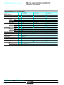
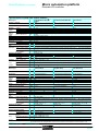
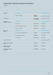
Selection guide
Micro automation platform
0
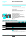
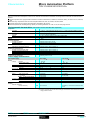
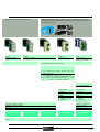
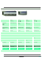
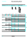
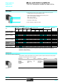
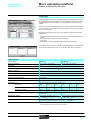
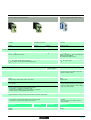
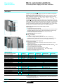
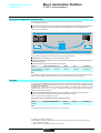
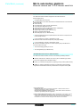
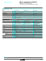
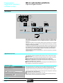
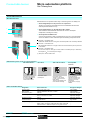
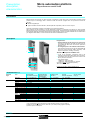
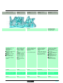
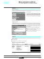
TSX 37-05/08/10/21/22 PLCs
For low to medium complexy control systems
Applications
Slot
No. of discrete I/O,
connection
Base
2 (1 equipped with discrete
I/O module)
3 (2 equipped with discrete
I/O module)
2 (1 equipped with discrete
Extension
–
–
2
Per HE 10 connector
Per terminal block
92
120
–
60
88
124
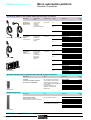
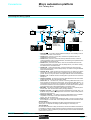
Emergency stop and limit switch monitoring
Preventa safety module
Remote I/O
Telefast 2
96 remote I/O (4 Nano PLCs) or
Number
Type
Input
$ 24 V, input " 115 V,
Connection sub-base
8, 12 or 16 channels, with or without DEL, with common or 2 terminals per channel
Adaptor sub-base
8 ou 16 channels
Integrated
No. of modules
Type of module
2 half-format modules
$ 5 V TTL, $ 24 V, $ 48 V, " 115 ou 230 V, 2 terminals per channel
Real-time clock
Analogue I/O
Remote
Control loops, 3 integrated functions : PID, PWM (pulse width modulation) et SERVO (discrete valve
Process control
Counting/positioning
Communication
8 inputs 12 bits (± 10 V, 0-10 V), 8 inputs 12 bits (0-20 mA, 4-20 mA),
4 differential inputs multirange 16 bits (high level, thermocouples, temperature probes),
4 output 11 bits + sign (± 10 V), 2 outputs 11 bits + sign (± 10 V, 0-20 mA, 4-20 mA),
4 inputs/2 outputs 12 bits (± 10 V, 0-10 V, 0-20 mA, 4-20 mA)
3 Nano analogue extensions
Integrated
No. of modules
Type of module
2 x 500 Hz channels using discrete inputs
Integrated
1 x RS 485 terminal port, Uni-Telway master/slave, Modbus
slave or character string protocol
2 half-format modules
1 or 2 x 40 kHz channels, 2 x 500 kHz channels for incremental encoders (Totem pôle or RS 422),
1 channel 1 MHz for SSI absolute encoder,
1 x RS 485 terminal port,
Modbus master/slave or
With PCMCIA card
Ethernet TCP/IP
Ethernet TCP/IP external module
Memory structure
Single task (cyclic or periodic), multi-task (cyclic or periodic master task, fast task)
Event-triggered (1 to 8 events)
11 Kword internal protected RAM memory
14 Kword internal protected RAM
Supply voltage
" 100/240 V (integrated $ 24 V sensor power supply)
Software structure
Standard I/O
$
Type
16 inputs
24 V,
12 relay ouputs
Connection
Via screw terminal block
$
2 x 16 inputs
24 V,
12 relay ouputs
" 100/240 V (integrated $ 24 V
16 inputs " 115 V or
$ 24 V depend. on model
12 relay ouputs/$ 24 V
depending on model
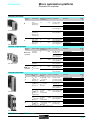
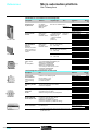
Type of PLC
TSX 37 05 028DR1
Pages
43050/13
0460Q-EN.FM/2
TSX 37 08 056DR1
TSX 37 10 /28// 1
Schneider Electric
0
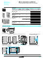
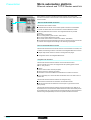
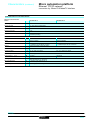
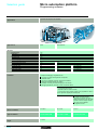
For control systems which require a signifiant
amount of processing (program and data) and:or
communication
I/O module)
For control systems which require low-cost
analogue I/O and fast counting functions
3 (non-equipped with discrete I/O module)
2
184
248
–
160
248 I/O on AS-i bus (total with “in-rack” discrete I/O)
input
$ 24 V, relay outputs
Integrated (seconds, minutes, hour, day, month, year)
8 inputs 8 bits (0-10 V, 0-20 mA, 4-20 mA)
1 ouput 8 bits (0-10 V)
4 half-format modules
each providing 3 inputs and 1 ouput (inputs 12 bits: 0-10 V, ± 10 V, 0-20 mA, 4-20 mA ; output 11 bits: 0-10 V, ± 10 V, 0-20 mA, 4-20 mA)
control) with MMI on CCX 17 operator panel (control and adjustment of 9 loops maximum).
2 x 500 Hz channels using discrete inputs and
2 integrated 10 kHz channels
4 half-format modules.
Uni-Telway master/slave,
character string protocol
1 fixed station auxiliary port and 1 terminal port (RS 485, protocole Uni-Telway master/slave, Modbus
master/slave or character string protocol)
1 PCMCIA card: RS 232/422/485 or current loop serial link, with Fipway/Modbus Plus network, Fipio bus
(Agent function)
or Modem (PPP) RS 232 serial link
Event-triggered (1 to 16 events with 2 priority levels)
20 Kword internal protected RAM memory
Extension via PCMCIA card up 64 Kwords + 128 Kwords (file storage)
memory
sensor power supply) or
$ 24 V depending of model
$
$
16 or 32 inputs
24 V depending on model
12 or 32 outputs
24 V depending on model
Via HE 10 connector
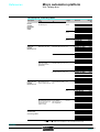
TSX 37 10 1// DTK1
Schneider Electric
TSX 37 21 001/101
TSX 37 22 001/101
0460Q-EN.FM/3
Micro Automation Platform
Presentation,
description,
selection
0
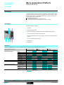
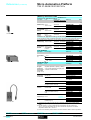
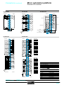
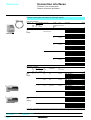
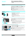
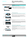
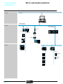
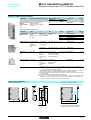
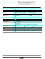
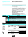
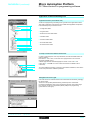
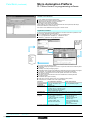
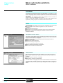
TSX 37-05 PLCs
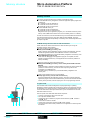
Presentation
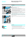
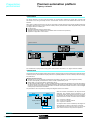
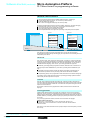
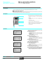
The TSX 37-05 PLC comprises a rack which integrates " 100/240 V power supply,
a processor including a 11 Kword memory (program, data and constants), 1 Flash
EPROM backup memory, a TSX DMZ 28DR discrete I/O module (16 inputs and
12 relay outputs) and an available slot.
The available slot can accept:
# 1 standard format discrete I/O module of any type.
# 2 half format discrete I/O, safety, analog I/O or counter modules.
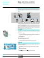
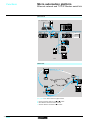
Description
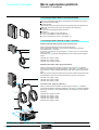
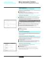
The TSX 37-05 PLC comprises:
2
3
1
1 2-slot rack.
2 Centralized display block.
3 Terminal port (TER) (Uni-Telway Master/Slave or Modbus slave protocol).
4 Cover for accessing the power supply terminals.
5 Discrete module with 16 inputs and 12 outputs, placed in the first slot (positions
1 and 2).
6 Cover for accessing optional battery.
7 Available slot.
4
8 6
5
7
8 Reset button.
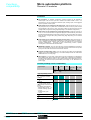
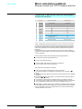
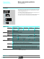
Selection
Selection of modules to be inserted in addition to the 16-input/12-output module present at rack no. 1
Type of module to be inserted
Discrete Inputs/Outputs
Preventa safety module
Analogue I/O
Counter/positioning channels
Max number of modules
1
2
Format
Standard
Half
Connection
Connector
Term.blk
8 inputs
12 inputs
32 inputs
4 outputs
8 outputs
32 outputs
16 inputs/outputs
28 inputs/outputs
64 inputs/outputs
4 or 8 inputs
2 or 4 outputs
4 inputs and 2 outputs
1 incremental code
channel
2 incremental code
channels
1 absolute encoder
channel
Insertion possible
Functions:
pages 43050/6 and 43050/7
43050-EN.FM/2
Characteristics :
pages 43050/11 and 43050/12
references:
pages 43050/13 and 43050/14
Dimensions, mounting:
page 43050/15
Schneider Electric
Micro Automation Platform
Presentation,
description,
selection
0
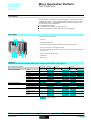
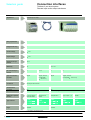
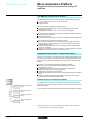
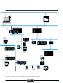
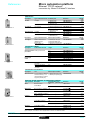
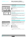
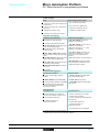
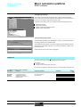
TSX 37-08 PLCs
Presentation
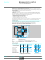
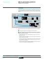
The TSX 37-08 PLC comprises a rack which integrates " 100/240 V power supply,
a processor including a 11 Kword memory (program, data and constants), 1 Flash
EPROM backup memory, 2 TSX DMZ 28DR discrete I/O modules (16 inputs and
12 relay outputs) and an available slot.
The available slot can accept:
# 1 standard format discrete I/O module of any type.
# 2 half format discrete I/O, safety, analog I/O or counter modules.
Description
2
3
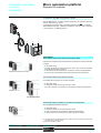
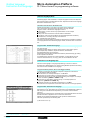
The TSX 37-08 PLC comprises:
1
1 3-slot rack.
2 Centralized display block.
3 Terminal port (TER) (Uni-Telway Master/Slave or Modbus slave protocol).
4 Cover for accessing the power supply terminals.
5 Two discrete modules with 16 inputs and 12 outputs, placed in the first and second slot
(positions 1 to 4).
6 Cover for accessing optional battery.
7 Available slot.
4
8
1
5
7
8 Reset button.
Selection
Selection of modules to be inserted in addition to the 16-input/12-output module present at rack no. 1
Type of module to be inserted
Discrete Inputs/Outputs
Preventa safety module
Analog I/O
Counter/positioning channels
Max number of modules
1
2
Format
Standard
Half
Connection
Connector
Term.blk
8 inputs
12 inputs
32 inputs
4 outputs
8 outputs
32 outputs
16 inputs/outputs
28 inputs/outputs
64 inputs/outputs
4 or 8 inputs
2 or 4 outputs
4 inputs and 2 outputs
1 incremental code
channel
2 incremental code
channels
1 absolute encoder
channel
Insertion possible
Functions:
pages 43050/6 and 43050/7
Schneider Electric
characteristics:
pages 43050/11 and 43050/12
references:
pages 43050/13 and 43050/14
Dimensions, mounting:
page 43050/15
43050-EN.FM/3
Micro Automation Platform
Presentation,
description,
selection
0
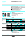
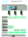
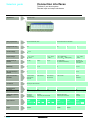
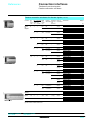
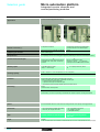
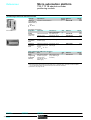
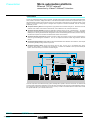
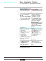
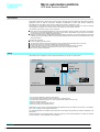
TSX 37-10 PLCs
Presentation
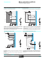
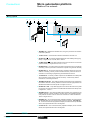
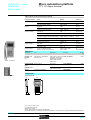
Compact and modular TSX 37-10 PLCs differ in their supply voltage and the type of
discrete I/O module fitted in the first slot.
Each TSX 37-10 configuration comprises a rack which integrates a power supply
($ 24 V or " 100/240 V), a processor including a 14 Kword RAM memory (program,
data and constants), a Flash EPROM backup memory, a real-time clock, a discrete
I/O module (28 or 64 I/O) and an available slot. A TSX RKZ 02 mini extension rack
enables the number of slots to be increased by 2 (4 positions).
Each available slot can accept:
# 1 standard format discrete I/O module of any type.
# 2 half format discrete I/O, safety, analog I/O or counter modules.
Also, TSX 37-10 PLCs can connect to the Ethernet network TCP/IP or to a Modem
via the TSX ETZ 410/510 external stand-alone module.
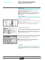
Description
2
4
3
1
12 6
5
7
8
11
10 9
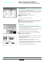
TSX 37-10 PLCs and the TSX RKZ 02 mini extension rack comprise:
1 2-slot base rack.
2 Centralized display block.
3 Terminal port (TER) (Uni-Telway or Modbus Master/Slave protocol).
4 Cover for accessing the power supply terminals.
5 28 or 64 discrete I/O module, placed in the first slot (positions 1 and 2).
6 Cover for accessing optional battery.
7 Mini extension rack with 2 available slots -(positions 5 to 8).
8 LED showing presence of $ 24 V.
9 Power supply terminals protected by removable cover, to connect an auxiliary
$ 24 V power supply if PLCs are supplied with " 100/240 V.
10 Earth terminal.
11 Connectors to the base PLC.
12 Reset button.
Selection
TSX 37-10 base PLC selection
Power supply
$ 24 V
" 110/240V
I/O module integrated in 1 st slot
Number of inputs
24 V
110/120 V
$
"
16
16
Connection
Connector
$
Number of outputs
Solid state
Relay
24 V
Reference
Term.blk
TSX 37 10 128DT1
TSX 37 10 128DTK1
TSX 37 10 128DR1
TSX 37 10 164DTK1
TSX 37 10 028AR1
TSX 37 10 028DR1
12
12
16
32
12
32
16
12
12
16
Selection of modules to be inserted (3 slots available, that is a maximum of 6 positions)
Type of module to be inserted
Discrete Inputs/Outputs
Preventa safety module
AS-i bus or I/O extension
Analog I/O
Counter/positioning
channels
Communication
Maximum number of modules (1)
1
2
4
8 inputs
12 inputs
32 inputs
4 outputs
8 outputs
32 outputs
16 inputs/outputs
28 inputs/outputs
64 inputs/outputs
6
Format
Stand.
Half
Connection
Connect. Term.blk
(2)
(2)
(2)
(2)
(3)
4 or 8 inputs
2 or 4 outputs
1 or 2 incremental encoder
channels
1 absolute encoder channel
Ethernet TCP/IP or external
Modem
External module
Possible selection or insertion
(1) With TSX RKZ 02 mini extension rack.
(2) This includes a standard format module to be inserted in the 1st slot of the PLC.
(3) The remote discrete I/O extension modules and AS-i bus modules are installed in position 4
which means that their use is mutually exclusive.
Functions:
pages 43050/6 and 43050/7
43050-EN.FM/4
characteristics:
pages 43050/11 and 43050/12
references:
pages 43050/13 and 43050/14
Dimensions, mounting:
page 43050/15
Schneider Electric
Micro Automation Platform
Presentation,
description,
selection
0
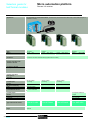
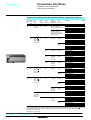
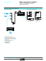
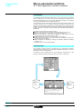
TSX 37-21/22 PLCs
Presentation
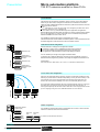
Modular TSX 37-21/22 PLCs differ in their supply voltage and/or the possibility of fast
counting and analogue functions integrated on the base.
Each PLC comprises: a 3-slot rack which integrates a power supply ($ 24 V or
" 100/240 V), a processor including a 20 Kword RAM memory (program, data
and constants), 1 Flash EPROM backup memory, 2 slots for a PCMCIA card
(1 communication card and 1 memory extension card of 64 Kwords maximum) and
a real-time clock. A TSX RKZ 02 mini extension rack enables the number of slots
to be increased by 2 (4 positions).
Each available slot can accept:
# 1 standard format discrete I/O module.
# 2 half format discrete I/O, safety, analog I/O or counter modules.
Also, TSX 37-21/22 PLCs can connect to the Ethernet network TCP/IP or to a
Modem via the TSX ETZ 410/510 external stand-alone module.
Description
TSX 37-21/22 PLCs and the TSX RKZ 02 mini extension rack comprise:
9
3
4
5 2
10
1
14
7
6
8 15
11 1 3-slot base rack (positions 1 to 6).
2 Slot reserved for a standard format module.
3 Centralized display block.
4 Terminal port (TER) (Uni-Telway or Modbus Master/Slave protocol).
5 Man-machine interface port labeled AUX.
6 Slot for a memory extension card.
7 Cover for accessing the power supply terminals.
8 Slot for a communication module.
9 On TSX 37-22, connectors for integrated analogue and counter functions.
10 Mini extension rack with 2 available slots (positions 7 to 10).
11 LED showing voltage presence of
24 V.
12 Power supply terminals protected by removable cover, to connect an auxiliary
13 12
24 V power supply if PLCs are supplied with
100/240 V.
13 Earth terminal.
14 Connectors to the base PLC.
15 Reset button.
$
$
"
Selection
Selection of modules to be inserted (5 slots available, that is a maximum of 9 positions)
Type of module to be inserted
Maximum number of modules (1)
1
3
4
5
Discrete
Inputs/Outputs
8 inputs
12 inputs
32 inputs
4 outputs
8 outputs
32 outputs
16 inputs/outputs
28 inputs/outputs
64 inputs/outputs
Preventa safety module
AS-i bus or I/O extension
Analog I/O
4 or 8 inputs
2 or 4 outputs
2 inputs and 4 outputs
Counting/
1 or 2 incremental encoder channels
positioning
1 absolute encoder channel
Communication Uni-Telway
(PCMCIA card on Serial link
processor)
Modbus
Modbus Plus
Fipway
Fipio Agent
Communication Ethernet TCP/IP or external Modem
9
(3)
(2)
Format
Stand.
Half
Connection
Connect. Term.blk
(2)
(2)
(2)
(2)
(2)
(2)
(2)
(3)
(4)
(4)
External module
Insertion possible
(1) With TSX RKZ 02 mini extension rack.
(2) Comprises a standard format module to be placed in 1st slot of the PLC.
(3) The remote discrete I/O extension modules and AS-i bus modules are installed in position 4
which means that their use is mutually exclusive.
(4) With a maximum of 2 (TSX AMZ 600/ASZ 200) modules in the base.
Functions:
pages 43050/6 and 43050/7
Schneider Electric
characteristics:
pages 43050/11 and 43050/12
references:
pages 43050/13 and 43050/14
Dimensions, mounting:
page 43050/15
43050-EN.FM/5
Micro Automation Platform
Functions
0
TSX 37-05/08/10/21/22 PLCs
Functions
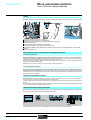
Discrete Inputs/Outputs
The range of in-rack discrete I/O modules offers several possibilities for meeting
requirements:
#
#
Cost-effective connection where a $ 24 V solution is required (mixed I/O modules
with HE type 10 connectors for direct connection to pre-actuators in the device
using cables with flying leads or direct connection to the TELEFAST2 pre-wired
system).
Connection to the screw terminal block on the front panel of mixed I/O modules.
A set of half format modules enable the PLC configuration to be adapted as closely
as possible to the user's requirements in terms of number, range of I/O and type of
connection.
For further details, see pages 43051/2 to 43051/13.
The TSX DPZ 10D2A Preventa type safety relay module provides a monitoring
function for the emergency stop pushbuttons or limit switches, and is adapted to
conform to the safety requirements stipulated in EN 954-1.
For further details, see pages 43308/2 to 43307/5.
Remote discrete I/O extension module
TSX 37-10/21/22 Micro PLCS offer two different possibilities for extending the I/O:
#
Either with the TSX STZ 10 remote discrete I/O extension module. The discrete
I/O of 4 Nano PLCs can be used at a distance of up to 200m (one of which can be
a Nano extension PLC).
These Nano PLCs can be used as remote discrete I/O or local slave PLCs.
For further details, see pages 40056/2 40056/3.
#
The AS-i sensor/actuator bus. Micro PLCs are connected to the AS-i bus via an
AS-i master module. In this case, the PLC becomes the master station on the bus
and manages a maximum of 248 I/O over a distance of up to 100 m (200 m with a
repeater).
For further details, see pages 43610/2 to 43613/3.
Analogue I/O and process control
Micro PLCs offer several ways of performing analogue processing:
#
#
#
For data input or commands which do not need a high resolution level, using I/O
integrated in TSX 37-22 PLCs.
For precise measurement and commands, using TSX AEZ/ASZ/AMZ /// half
format analogue I/O modules.
To locate analog I/O remotely via the TSX STZ 10 rackmaster module with
TSX 37-10/21/22 PLCs. The latter enables the use of three TSX AMN 400/ analog
extensions, each equipped with 3 analogue inputs and one analog output.
For further details, see pages 40055/2 and 40055/3, 43053/2 to 43053/7.
Micro PLCs have, as standard, process control functions which can be accessed
by the user via the PL7 Micro, PL7 Junior or PL7 Pro programming software.
For further details, see pages 43531/2 and 43531/3, 43100/2 to 43100/17.
(1) I/O TSX AMZ 600 analog modules require a MIcro PLC with a 4 5.0 operating system installed
with 4 4.2 PL7 Micro/Junior/ Pro version software.
Description :
pages 43050/2 to 43050/5
43050-EN.FM/6
characteristics:
pages 43050/11 and 43050/12
references:
pages 43050/13 and 43050/14
Dimensions, mounting:
page 43050/15
Schneider Electric
Functions (continued)
Micro Automation Platform
0
TSX 37-05/08/10/21/22 PLCs
Counting/positioning
Counter modules Micro PLCs offer several ways of counting:
#
#
#
Using 500 Hz discrete inputs (2 up/down counter channels with upcounting,
downcounting or up/down counting functions, with or without detection of direction
of operation).
10 kHz counter channels integrated into TSX 37-22 PLC bases (2 10 kHZ fast
counter channels, with 1 channel having down-counting functions as above).
Counting/positioning TSX CTZ modules /A, from 40...500 kHz or TSX CTZ 2B,
from 200 kHz...1 MHz (1). These half format modules are inserted in the available
slots in the base rack.
For further details, see pages 43054/2 and 43054/7, 43050/2 to 43050/5.
Communication
Micro PLCs offer several possibilities:
#
#
#
Integrated communication which offers cost-effective dialogue functions via the
terminal port for TSX 37-05/08/10 PLCs or via the terminal and man-machine
interface ports for TSX 37-21/22 PLCs. These RS 485 type non-isolated links use
Uni-Telway Master/slave, Modbus slave or character string. Also TSX 37-10/21/22
PLCs integrate Modbus Master protocol (1).
PCMCIA format communication card for TSX 37-21/22 PLCS. They have a
dedicated slot for the PCMCIA format communication card ("Full-duplex"
asynchronous serial link, FIPIO, Uni-Telway, or Modbus/Jbus, Modbus Plus and
Fipway network).
Ethernet TCP/IP 10/100 MHz external modules. The module connects to the
terminal port of TSX 37-10/21/22 PLCs and has Uni-TE and Modbus messaging.
It allows connection to an external modem using PPP protocol.
For further details, see pages 43609/2 to 43599/5.
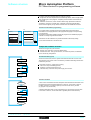
Fan modules
TSX FAN //P fan modules installed above Micro PLCs ensure a forced air
convection, which creates a uniform ambient temperature within the enclosure and
eliminates any hot spots which might exist.
Fan modules are required when the ambient temperature is between 60 °C and
70 °C. Forced ventilation is used to eliminate hot spots (2).
Three types of fan module are available: $ 24 V, " 110 V and " 220 V.
One fan module is required for a TSX 37-05/08/10/21/22 configuration, two fan
modules are required for a TSX 37-10/21/22 configuration with the TSX RKZ 02
mini rack.
TSX FAN //P
TSX 37-05/10
TSX 37-10 + TSX RKZ 02
TSX 37-08/21/22
TSX 37-21/22 + TSX RKZ 02
CDescription :
pages 43050/2 to 43050/5
Schneider Electric
characteristics:
pages 43050/11 and 43050/12
(1) The TSX CTZ 1B module or the Modbus slave protocol require a MIcro PLC with a 4 5.0
operating system installed with 4 4.2 PL7 Micro/Junior/ Pro version software.
(2) For an ambient temperature of between 25 °C and 60 °C, the use of fan modules increases
the MBTF.
references:
pages 43050/13 and 43050/14
Dimensions, mounting:
page 43050/15
43050-EN.FM/7
Memory structure
Micro Automation Platform
0
TSX 37-05/08/10/21/22 PLCs
Memory structure
The memory structure of Micro PLCs consists of two distinct zones:
# An internal RAM memory designed to receive the application (data, program and
constants) of
5 11 Kwords for TSX 37-05/08 PLCs,
5 14 Kwords for the TSX 37-10 PLC,
5 20 Kwords for TSX 37-21/22 PLCs.
# A Flash EPROM memory of:
5 12 Kwords for TSX 37-05/08 PLCs,
5 16 Kwords for TSX 37-10/21/22 PLCs
designed to back up the application program (11 or 14 Kwords maximum) and to
back up 1024 %MW internal words in the event of a battery failure or no battery.
For TSX 37-21/22 PLCs, the internal RAM memory can be extended via a 32 Kword
or 64 Kword PCMCIA memory card, either RAM or Flash EPROM. The same
memory card incorporates the possibility of containing 128 K words designed to back
up recipe or log files.
PCMCIA memory extension cards for TSX 37-21/22 PLCs
These cards can be used to extend the PLC internal memory for storing the
application program and constants.
Two types of memory card are available:
# Battery-backed RAM type memory card
Used in particular during application program creation and debugging, this card
enables all application transfer and modification services in online mode.
The memory is backed up by a removable battery integrated in the memory card.
# Flash EPROM type memory card
Used when the debugging of the application program is complete, this card
enables one global transfer only of the application and avoids the problems of
backup via battery.
A third type of card can also be used to store files:
# Battery-backed RAM type memory card or battery-backed RAM and Flash
EPROM
Used particularly in association with the Modem link, these are used to extend the
processor's internal memory, and also to store recipe or log files for later
consultation via a telephone link.
The RAM memory is backed up by a removable battery integrated in the
memory card.
Another type of PCMCIA memory card is available:
# Backup type memory card (for TSX 37-21/22 PLCs)
Previously loaded with the application program, this card is used to reload the
application program into the internal RAM memory and the internal Flash EPROM
memory of the processor, without requiring the use of a programming terminal.
Program loader
The TSX PGR LDR module is designed to simplify duplicating or updating
applications on Nano and Micro PLCs without the need for a programming terminal.
An application (15 K words maximum in internal RAM) can be transferred from a PLC
in the TSX PGR LDR module (and saved within it), then transferred from the TSX
PGR LDR module in a PLC.
1
The front panel of the TSX PGR LDR module comprises:
1 A cord for connecting to the PLC terminal port.
2 Four operation indicator LEDs.
3 A W/R button which selects the program transfer direction (PLC module or
module PLC).
4 A GO button to start the transfer.
5 A Write Only switch which prevents PLC module transfer.
6 A Program Protect switch which protects the PLC application as read-only after
the transfer.
2
3
6
5
4
Functions:
pages 43050/6 and 43050/7
43050-EN.FM/8
characteristics:
pages 43050/11 and 43050/12
references:
pages 43050/13 and 43050/14
Dimensions, mounting:
page 43050/15
Schneider Electric
Memory structure (continued) Micro Automation Platform
0
TSX 37-05/08/10/21/22 PLCs
Application memory
The application memory is divided into memory zones, which are physically shared
between the internal RAM memory and the PCMCIA memory card (if the TSX
37-21/22 PLC has a memory card):
#
#
#
#
#
The application data zone which is always is the internal RAM memory.
The application program zone in the internal RAM memory or on the PCMCIA
memory card.
The constants zone in the internal RAM memory or on the PCMCIA memory card.
The Flash EPROM zone for the application program backup, the constants and
1 K internal words.
The file storage zone in the PCMCIA memory card.
If the content of the RAM memory is lost (battery fault or no battery) then the content
of the Flash EPROM memory (program, constants and 1 K internal words) is
automatically transferred to the internal RAM memory. The backup copy of the
application in the Flash EPROM memory requires that the PLC does not have a
PCMCIA memory extension card and that the size of the program and the constants
does not exceed 16 Kwords.
Two types of application memory organization are possible for Micro PLCs
depending on whether the PLC is equipped with a memory extension in the form of a
PCMCIA card:
Application in the internal RAM
The application is loaded entirely in the battery-backed internal RAM of the processor
with a capacity of:
Backup copy
Flash
EPROM
12/16
Kwords
RAM
internal
11/14/20
Kwords
TSX 37-05/08/10/21/22 (without PCMCIA card)
Data
1
Program
2
#
Constants
3
#
#
Programs and
constants
1 Kwords int. %MW
1 Application data (17.5 Kwords maximum).
2 Descriptor and executable code for tasks.
3 Constant words, initial values and configuration.
Internal
RAM
Backup copy
Flash
EPROM
PCMCIA
card
1
2
3
4
128 32/64
20
16
Kword Kwords Kword Kwords
TSX 37-21/22 (with a PCMCIA card)
Data
1
1 Kwords int. %MW
Program
2
Constants
3
File storage
4
Application data (17.7 Kwords maximum).
Descriptor and executable codes for task.
Constant words, initial values and configuration.
According to the PCMCIA card model.
11 Kwords for TSX 37-05/08, shared, for example: as 2 Kwords of application data
and 7 Kwords of the program and its constants.
14 Kwords for TSX 37-10, shared, for example: as 500 words of application data
and 13.5 Kwords of the program and its constants.
20 Kwords for TSX 37-21/22, shared, for example: as 4 Kwords of application data
and 16 Kwords of the program and its constants.
Application in the internal Flash EPROM
The total volume is equal to the application volume in RAM, limited to 11 Kwords
or 15 Kwords, to which the backup of the first 1024 data words (%MW) is added.
Application in the PCMCIA card
The PCMCIA memory card contains the program and the constants.
The storage zone for 128 Kword files (available according to the PCMCIA card
model) can be used for distributed applications, for storing information which can be
consulted remotely via Modem.
This zone can also be used for storing manufacturing recipes.
Internal RAM data
The data zone can be extended to 17.5 Kwords, and is only held in the PLC
internal RAM.
Data backup
The first 1024 words are backed up by the PLC internal Flash EPROM memory.
PL7 Micro/Junior/Pro software aids the application designer in the management
of the structure and the occupation of memory space for Micro PLCs.
Application protection
Whatever the PLC's memory structure is: application in internal RAM or on the
PCMCIA card, it is possible to protect the structure to prohibit access (reading or
program modification) in online mode using PL7 Micro/Junior/Pro software.
Backup application
Micro TSX 37-21/22 PLCs make it possible to save the 32 K words maximum
application (programs and constants) on a Backup TSX MFP BAK 032P memory
card. The internal RAM memory can thus be reloaded with the contents of this
Backup memory card. This Backup function is not available if the application runs on
a PCMCIA RAM or Flash EPROM memory card.
Functions:
pages 43050/6 and 43050/7
Schneider Electric
characteristics:
pages 43050/11 and 43050/12
references:
pages 43050/13 and 43050/14
Dimensions, mounting:
page 43050/15
43050-EN.FM/9
Micro Automation Platform
Centralized display,
description
0
TSX 37-05/08/10/21/22 PLCs
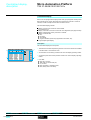
Centralized display
Micro PLCs are equipped with a display block which groups together centrally all the
data required for the control, diagnostics and maintenance of the PLC and all its
modules, as well as simple man-machine interface functions.
The centralized display provides:
#
#
#
#
#
Display of the local or remote I/O channel states
(I/O of Nano PLCs).
Display of devices on the AS-i bus and AS-i bus diagnostics (see page 42718/2).
Display of diagnostics of faulty channels or modules.
Display of internal data:
5 bits,
5 bit strings,
5 word strings,
5 program variables (active steps, application information, etc).
4-digit multiple digital display.
Description
The centralized display block comprises:
2
1
BASE
EXT
64 16
R I/O
WRD
64 16
4
8 12
0
4
8 12
0
4
8 12
1
5
9 13
1
5
9 13
1
5
9 13
2
6 10 14
2
6 10 14
2
6 10 14
3
7 11 15
3
7 11 15
3
7 11 15
0
4
8 12
0
4
8 12
0
4
8 12
1
5
9 13
1
5
9 13
1
5
9 13
2
6 10 14
2
6 10 14
2
6 10 14
3
7 11 15
3
7 11 15
3
7 11 15
Functions:
pages 43050/6 and 43050/7
1 Three blocks of 32 LEDs representing the slots in which the modules are installed
in the base rack or mini extension rack.
RUN
0
43050-EN.FM/10
3
DIAG
64 16
2 An information line consisting of LEDs which show the display operating modes.
TER
> 1s.
DIAG
I/O
ERR
4
BAT
characteristics:
pages 43050/11 and 43050/12
3 A command push button which provides access to the various display operating
modes.
4 Five LEDs:
5 RUN, PLC run/stop,
5 TER, traffic on the terminal port,
5 I/O, I/O fault,
5 ERR, processor or application fault,
5 BAT, battery fault or no battery.
references:
pages 43050/13 and 43050/14
Dimensions, mounting:
page 43050/15
Schneider Electric
Micro Automation Platform
Characteristics
0
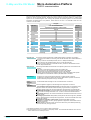
TSX 37-05/08/10/21/22 PLCs
Micro PLCs have been developed to conform to the national and international standards concerning electronic devices for industrial control
systems:
# Specific requirements for programmable controllers: functional characteristics, resistance, robustness, safety, etc. IEC 61131-2, CSA 22-2,
UL 508.
# Merchant navy requirements from the main European bodies: BV, DNV, GL, GOST, LR, RINA, RRS.
# European directives (low voltage, electromagnetic compatibility), & marking.
# Electrical qualities and self-extinguishing capacity of insulating materials: UL 746C, UL 94, etc. See page 43311/3.
Environmental characteristics (characteristics common to all Micro PLC components)
Temperature
Operation
Storage
°C
°C
Relative humidity
Operation
Storage
0...+ 60 (+ 5...+ 55 conforming to IEC 61131-2), 0…+ 70 with TSX FAN ventilation modules
-25...+ 70 (conforming to IEC 61131-2)
10 %...95 %, without condensation
5 %..95 % conforming to IEC 61131/2 without condensation
Altitude
m
0…2000
Mechanical withstand
Resistant to vibrations
Resistant to shocks
Conforming to IEC 68-2-6, Fc test
Conforming to IEC 68-2-27, Ea test
Resistant to electrostatic discharge
Withstand to electrostatic discharge
Conforming to IEC 1000-4-2, level 3 (1)
Resistance to HF interference
Resistant to electromagnetic fields
Resistant to rapid transient bursts
Resistant to shock waves
Resistant to damped oscillatory waves
Conforming to IEC 1000-4-3, level 3 (1)
Conforming to IEC 1000-4-4, level 3 (1)
Conforming to IEC 1000-4-5
Conforming to IEC 1000-4-12
Resistance to LF interference
Conforming to IEC 61131-2
Power supply characteristics
Type of power supply
power supply
"
Voltage
Nominal
Limit (including ripple)
V
V
" 100...240
" 90…264
Frequency
Current
Nominal (limit)
Nominal input
Inrush (2)
Hz
A
A
50-60 (47-63)
≤ 0.7 ( 100 V), ≤ 0.3 (
≤ 60
Primary
Micro-breaks
$
$
$
Isolation
Dielectric resistance
Primary/secondary
Functions:
pages 43050/6 and 43050/7
Schneider Electric
$
$ 24
$ 19.2...30V
" 240 V)
possible up to 34 V for 1 hr per 24 hrs
–
2
≤ 60
≤ 1/2 period, repetition ≥ 1 s
≤ 10 ms, repetition ≥ 1 s
W
24 (32 peak)
16 (18 peak)
A
A
A
2.8 (3.2 peak)
0.5 (0.6 peak)
0.4 (0.6 peak)
2.8 (3.2 peak)
–
–
Yes
Yes
Yes
Yes
Accepted duration
Secondary
Power
Total useful (typical)
Output currents
5 V output
Output 24 VR (for relay outputs)
24 V output sensors
Protection integrated on the outputs against
Overloads
Short-circuits
"
power supply
V rms
references:
pages 43050/13 and 43050/14
2500 - 50/60 Hz
No isolation, 0 V internal connected to the PLC
ground
(1) Minimum level in the test conditions defined by the standards.
(2) Values to be taken into account when starting up several devices at the same time or when
sizing protection devices.
Dimensions, mounting:
page 43050/15
43050-EN.FM/11
Micro Automation Platform
Characteristics (continued)
0
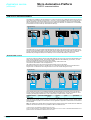
TSX 37-05/08/10/21/22 PLCs
Processor characteristics
Type of PLC
TSX 37-05
TSX 37-08
TSX 37-10
TSX 37-21
Max. no. (without remote)
Max. no. (Nano remote I/O)
Max. no. (remote I/O on AS-i bus)
Max. no. of modules 28/32
channels
Max. no. of 64 channel modules
60/92 (1)
–
–
2
120/184 (1)
–
–
3
124/184 (1)
200/264 (1)
340/404 (1)
4
160/248 (1)
236/328 (1)
376/468 (1)
5
1
1
2
3
Safety
Max. no. of Preventa modules
2
2
6
8
Analog
Max. no. of modules
No. of integrated channels
2 (max. 16 I or 8 O)
–
TSX 37-22
Functions
I/O
Counting/positionin (2)g
Max. no. of modules
No. of integrated channels
No. of channels on discrete
inputs
Max. no. of modules
Communication
Integrated channels (terminal
port)
No. of PCMCIA card
Real-time
clock
2
–
2
2
2
2
4 (max. 32 I or 16 O)
–
9 (8 I and 1 O)
2 (3)
2 (3)
4 (3)
–
2
4 (3)
1 RS 485 channel (Uni-Telway
master/slave Modbus slave or
character mode)
–
1 RS 485 channel (Uni-Telway master/slave Modbus
master/slave or character mode)
–
1
1
Memory
Internal RAM which can be
backed up
PCMCIA memory card
Max. memory size
Application
structure
Kwords
11
Kwords
Kwords
–
11
Execution time for 1 k instructions
100 % Boolean
65 % Boolean and 35 %
numerical
PLC types
Memory capacity
PCMCIA card
Data (% MWi)
Constants (% KWi)
File storage
Program Ladder (LD)
100 % Boolean
65 % Boolean and 35 %
numerical
List (IL)
100 % Boolean
65 % Boolean and 35 %
numerical
Structured 100 % Boolean
Text (ST)
65 % Boolean and 35 %
numerical
System overhead
14
20
14
32/64 + 128 (file storage)
64
1
1
8
Master task
Fast task
Event processing
Execution time (standard instructions)
Boolean instruction
numerical instruction
11
16 (where 1 has priority)
µs
µs
0.25
4.81
0.25
4.81
0.25
4.81
0.13 (0.19 with PCMCIA card)
4.50
ms
0.33
0.33
0.33
0.17 (0.25 with PCMCIA card)
ms
4.08
TSX 37-05
4.08
TSX 37-05
4.08
TSX 37-10
3.71 (3.76 with PCMCIA card)
TSX 37-21/22
Kwords
Kwords
Kwords
–
1 (4)
128 (4)
–
–
1 (4)
128 (4)
–
–
1 (4)
128 (4)
–
–
1 (4)
128 (3)
–
32 Kwords
17.5
128 (3)
128
64 Kwords
17.5
128 (3)
128
kinst.
2
2
4
6.6
13.5
28.1
kinst.
kinst.
1.1
2.5
1.1
2.5
2.1
5.1
3.9
8.5
8.8
17.2
18.6
35.9
kinst.
kinst.
1.2
1.6
1.2
1.6
2.4
3.4
4.4
5.6
10
11.5
21
23.9
kinst.
1.2
1.2
2.4
4.4
10
21
ms
1.9
1.9
1.9
1.6
2.3
2.3
(1) 1st value for connection via terminal block, 2nd value via HE 10 type connector.
(2) Maximum number of counting/positioning channels, see page 43054/2.
(3) TSX CTZ
counting/positioning modules, only in the Micro base.
(4) Default size, can be extended, but will have an adverse effect on the size of the application
program.
//
Functions:
pages 43050/6 and 43050/7
43050-EN.FM/12
references:
pages 43050/13 and 43050/14
Dimensions, mounting:
page 43050/15
Schneider Electric
Micro Automation Platform
References
0
TSX 37-05/08/10/21/22 PLCs
Basic TSX 37-05/08 PLC configurations (1 slot available)
Power supply Integrated memories Integrated memory
Discrete I/O modules
RAM
Flash
Type
Connection
EPROM
"
11
12
100…240 V Kwords + Kwords
data
memory
Mass
Reference
(1)
kg
1 modules Via screw
TSX 37 05 028DR1
with 16 I
terminal block
24
(supplied)
V,12 O relay
2.370
2 modules Via screw
TSX 37 08 056DR1
with
terminal block
16 I
24 V, (supplied)
12 O relay
2.720
$
$
TSX 37 05/10 /28//1
Basic TSX 37-10 PLC configurations (1 slot available)
Power supply Integrated memories Integrated memory
Discrete I/O modules
RAM
Flash
Type
Connection
EPROM
$ 24 V
14
15
Kwords + Kwords
data
memory
Mass
Reference
(1)
kg
$
1.870
$
1.900
16 I
24 V Via screw
TSX 37 10 128DT1
12 Solid state terminal block
O 0.5 A
(supplied)
16 I
24 V Via screw
TSX 37 10 128DR1
12 O relay
terminal block
(supplied)
$
TSX 37 10 128DTK1
1.740
$
TSX 37 10 164DTK1
1.820
16 I
24 V Via HE 10
12 Solid state type
O 0.5 A
connector
TSX 37 08 056 DR1
32 I
24 V Via HE 10
32 Solid state type
O 0.1 A
connector
"100…240 V
14
15
Kwords + Kwords
data
memory
16 I
115 V Via screw
TSX 37 10 028AR1
12 O relay terminal block
(supplied)
"
1.910
16 I
24 V Via screw
TSX 37 10 028DR1
12 O relay terminal block
(supplied)
$
1.910
Basic TSX 37-21/22 PLC configurations (3 slots available)
Supply
TSX 37 10 164DTK1
Integrated memories Integrated functions
RAM
Flash
EPROM
Reference
(1)
20
Kwords
+ data
memory
–
TSX 37 21 101
1.720
8 analog inputs 0-10 V
1 analog output 0-10 V
1 Up/down counter
10 kHz
1 counter 10 kHz
TSX 37 22 101
1.750
20
15 Kwords –
100…240 V Kwords +
data
memory
8 analog inputs 0-10 V
1 analog output 0-10 V
1 Up/down counter
10 kHz
1 counter 10 kHz
TSX 37 21 001
1.720
TSX 37 22 101
1.750
Number
maximum
Reference
Mass
kg
1 mini rack per PLC
TSX RKZ 02
0.630
$ 24 V
5 Kwords
"
TSX 37 22 /01
Mass
kg
Mini extension rack
Capacity
Use
2 slots (possibility PLCs
of 4 positions)
TSX 37-10/21/22
Documentation
See page 43901/2
Micro base and module installation manual
(1) Product supplied with multilingual installation guide: English, French, German, Italian and
Spanish.
TSX RKZ 02
Description:
pages 43050/2 and 43050/5
Schneider Electric
Functions:
pages 43050/6 and 43050/7
characteristics:
pages 43050/11 and 43050/12
-
Dimensions, mounting:
page 43050/15
43050-EN.FM/13
References (continued)
Micro Automation Platform
0
TSX 37-05/08/10/21/22 PLCs
Memory extension cards (PCMCIA type 1)
Extension for application memory
Description
Use
Memory size
Reference
Application File storage
Mass
kg
RAM memory PLCs
TSX 37-21/22
Flash EPROM PLCs
Memory
TSX 37-21/22
TSX MRP ///P
Backup
card(1)
PLCs
TSX 37-21/22
32 Kwords –
TSX MRP 032P
0.030
64 Kwords –
TSX MRP 064P
0.030
32 Kwords –
TSX MFP 032P
0.025
64 Kwords –
TSX MFP 064P
0.025
32 Kwords –
TSX MFP BAK 032P
0.025
Extension for application memory and file storage in RAM memory
These cartridges are used for distributed applications, as well as for storing information which can
be consulted remotely via Modem. They can also be used to store manufacturing recipes.
RAM memory TSX 37-21/22
Flash memory TSX 37-21/22
EPROM
TSX/PMX/PCX
Premium
32 Kwords 128 Kwords TSX MRP 232P
0.060
64 Kwords 128 Kwords TSX MRP 264P
0.060
32 Kwords 128 Kwords TSX MFP 232P
0.060
64 Kwords 128 Kwords TSX MFP 264P
0.060
Fan modules
Description
Reference
Mass
kg
TSX FAN D2P
0.500
TSX FAN A4P
0.500
TSX FAN A5P
0.500
Unit Weight
Mass
kg
Program
Simplifies duplication, updating or backup
of 15 Kwords applications (program) and
loader with
terminal port constants in internal RAM
conn. cable
(length: 0.3 m)
TSX PRG LDR
0.150
Connection
accessories
Discrete I/O
See page 43051/10
–
Discrete I/O with Telefast 2
See pages 14025/2
and 14025/3
–
Integrated analog I/O
See page 43051/10
–
Integrated counter channels
See page 43053/5
–
Fan modules
(2)
TSX FAN //P
Power supply
$ 24 V
" 100…120 V
" 200…240 V
Separate parts
Description
Backup
batteries
Use
TSX 37-05/08/10/21/22
internal RAM
–
TSX PLP 01
0.030
Pack of 10
TSX PLP 101
0.320
TSX BAT M01
0.010
RAM type PCMCIA memory –
card
Cover for
TSX 37-05/08/10/21/22
empty slot (3) PLCs
Sold in
TSX RKA 01
individual
batches of 10
0.150
Memory extension cards
0.030
TSX P CAP
(PCMCIA type 1)
(1) Card previously loaded to enable the Micro application program to be updated without
needing a programming terminal (the program must be entirely contained in the internal
RAM).
(2) One fan module for a TSX 37-05/08/10/21/22 configuration, two fan modules for a
TSX 37-10/21/22 configuration with mini rack TSX RKZ 02. Required for an ambient
temperature between 60 °C and 70 °C.
(3) Cover to be mounted in positions which do not hold a module to obtain IP 20 level of protection.
Gripper
TSX PRG LDR
Description:
pages 43050/2 and 43050/5
43050-EN.FM/14
Functions:
pages 43050/6 and 43050/7
characteristics:
pages 43050/11 and 43050/12
Dimensions, mounting:
page 43050/15
Schneider Electric
Micro Automation Platform
Dimensions,
mounting
0
TSX 37-05/08/10/21/22 PLCs
Dimensions, mounting
Front view
Mounting
c
108,3 (1)
a
140
17
AF1-AE4
b
132,5 (2)
J
H
152 (3)
a
TSX 37 05 028DR1
170.3
TSX 37 08 056DR1
227.9
TSX 37 10 028/128/164 1
170.3
TSX 37 21/22 01
227.9
(1) Empty PLC
(2) With screw terminal block
(3) With HE 10 type or SUB-D connectors
(4) Fixing holes for M4 screws
b
–
–
282.7
341.4
//
/
(4)
G
5,5
151
151
5,5
Side view
c
–
19
–
19
TSX 37 05 028DR1
TSX 37 08 056DR1
TSX 37 10 028/128/164
TSX 37 21/22 01
/
//1
G
159.2
198.9
159.2
198.9
H
–
–
271.7
311.4
J
5
24
5
24
Mounting for TSX FAN //P modules
32,5
58
54
110
138
140
146
150
Installation regulations
100
(1)
(3)
100
150
(1)
(1)
(3)
(1)
150
(1)
(1)
(2)
(1) ≥ 50 mm
(2) Switch gear or enclosure
(3) Cable ducting or wiring clip
Description:
pages 43050/2 and 43050/5
Schneider Electric
Functions:
pages 43050/6 and 43050/7
characteristics:
pages 43050/11 and 43050/12
references:
pages 43050/13 and 43050/14
43050-EN.FM/15
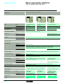
Selection guide for
standard format modules
Micro automation platform
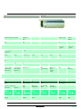
Discrete I/O modules
Applications
I/O connection on screw terminal block : via bare wires, via wires fitted with cable ends, or wires fitted with open or
Type
Nature
32 inputs
Inputs
24 V
Connection
Connection via screw terminal block (supplied with the module)
$
$
32 outputs
Outputs
24 V solid state 0.5 A
$ " relay 2A (Ith)
32 outputs
Outputs /
Possible association with
Telefast 2 sub-base
Connection sub-base
I/O adaptor sub-base
Possible association
with systems :
Tego Dial
Tego Power
Isolated inputs
Control
IEC 1131-2
conformity
Logic
Prox. sens. compat.
conforming to standard
IEC 947-5-2
Sensor voltage monitoring
Type 2
Positive
$ 2-wire, $/" 2-wire,
$ 3-wire PNP
Isolated outputs
Control
IEC 1131 conformity
Protection
Logic
Type of discrete I/O module
TSX DEZ 32D2
Pages
43051/9
0466Q-EN.FM/2
Preactuator voltage monitoring
Configurable fallback of outputs
Yes
Protected
Positive
Configurable fallback of outputs
TSX DSZ 32T2
TSX DSZ 32R5
–
Non-protected
–
Schneider Electric
closed tags (minimum cross-section 0.28 mm2, maximum 1.5 mm2)
$
16 inputs/12 outputs
Inputs
24 V
Relay outputs 3 A (Ith)
"
Inputs
100…120 V
Relay outputs 3 A (Ith)
I I/O connection on HE 10 type connector : with preformed
cables with flying leads (cross-section 0.324 mm2),
ribbon cables (cross-section 0.08 mm2) or connection
cables (cross-section 0.324 mm2).
$
$
$
$
Inputs
24 V
Outputs
24 V/0.5 A
Inputs
24 V
Outputs
24 V/0.5 A
$
$
32 inputs/32 outputs
Inputs
24 V
Outputs
24 V/0.1 A
Connection via 20-way HE 10 connector
8, 12 or 16 channels, with or without LED, with common or
terminals per channel
"
$
$
"
$
$
"
Inputs : 16 channels
5 V TTL,
24 V,
48 V,
48 V,
115 V or 230 V, 2 terminals per channel
Outputs : 8 or 16 chann. with 1 N/O, 1 or 2 C/O or solid state relays
5…48V,
24 V,
24…240 V 1 or 2 terminals per channel
$
Yes (see page 15000/2)
Yes (see page 15020/2)
Sensor voltage monitoring
Sensor voltage monitoring
Sensor voltage monitoring
Type 1
Positive/Negative
Type 2
–
Type 1
Positive
$ 2-wire,
$ 3-wire PNP/NPN
$/" 2-wire, " 2-wire
Configurable fallback of outputs
Preactuator voltage monitoring
Configurable fallback of outputs
Yes
Protected
Positive
–
Non-protected
–
TSX DMZ 28DR
$ 2-wire,
$ 3-wire PNP
TSX DMZ 28AR
TSX DMZ 28DT
TSX DMZ 28DTK
TSX DMZ 64DTK
43051/9
Schneider Electric
0466Q-EN.FM/3
Selection guide for
half-format modules
Micro automation platform
Discrete I/O modules
Applications
I/O connection on screw terminal block : via bare wires, via wires fitted with cable ends, or wires fitted with open or
maximum 1.5 mm2)
Type
Nature
12 inputs
Inputs
24 V
Connection
Connection via screw terminal block (supplied with the module)
$
"
8 inputs
Inputs
100…120 V
Inputs
" 200…240 V
$ " relay 3 A (th)
8 outputs
Outputs /
Possible association with
Telefast 2 sub-base
Connection sub-base
I/O adaptor sub-base
Possible association
with systems :
Tego Dial
Tego Power
Isolated inputs
Control
IEC 1131-2 conformity
Logic
Prox. sens. compat. conforming
to standard IEC 947-5-2
Sensor voltage
monitoring
Sensor voltage
monitoring
Sensor voltage
monitoring
Type 1
Type 2
Type 1
$
$
–
$/" 2-wire, " 2-wire
–
Positive/negative
2-wire,
3-wire PNP/NPN
" 2-wire
Isolated outputs
Control
Configurable fallback of
outputs
IEC 1131 conformity
Protection
Logic
–
Non-protected
–
Type of discrete I/O module
TSX DEZ 12D2
Pages
43051/9
0467Q-EN.FM/2
TSX DEZ 08A4
TSX DEZ 08A5
TSX DSZ 08R5
Schneider Electric
closed tags (minimum cross-section 0.28 mm2,
$
4 outputs
Outputs
24 V/2 A
I/O connection on HE 10 type connector : with preformed cables with flying leads
(cross-section 0.324 mm2) ribbon cables (cross-section 0.08 mm2) or connection cables
(cross-section 0.324 mm2).
$
$
8 outputs
Ouputs
24 V/0.5 A
12 inputs
Inputs
24 V
$
$
8 I/O
Inputs
24 V
Outputs
24 V/0.5 A
Connection via 20-way HE 10 connector
8, 12 or 16 channels, with or without LED, with common or 2
terminals per channel
Inputs : 16 channels $ 5 V TTL, $ 24 V, $ 48, " 48 V
" 115 V or 230 V, 2 terminal per channel. Outputs: 8 or 16
chan. with 1 N/O, 1 or C/O or solid state relays, $ 5... 48 V,
$ 24 v, " 24...240V 1 or 2 terminals per channel
Yes (see page 15000/2)
Yes (see page 15020/2)
Sensor voltage
monitoring
Sensor voltage
monitoring
Type 2
Positive
Type 1
Positive
$ 2-wire, $/" 2-wire,
$ 3-wire PNP
Preactuator voltage
monitoring. Configurable
fallback of outputs
Yes
Protected
Positive
Preactuator voltage monitoring
Configurable fallback of outputs
Yes
Protected
Positive
TSX DSZ 04T22
$ 2-wire
$ 3-wire PNP
TSX DSZ 08T2
TSX DSZ 08T2K
TSX DEZ 12D2K
TSX DMZ 16DTK
43051/9
Schneider Electric
0467Q-EN.FM/3
Micro automation platform
Connection principles
0
Discrete I/O modules
Connecting modules with screw terminal blocks
The screw connection terminal blocks are fitted with a removable cover ensuring :
# The screws are held in place
# Personnel safety
Each terminal on a screw terminal block can accept bare wires or wires fitted with
cable ends, with closed or open tags. The capacity of each terminal is :
# Minimum :
5 1 wire 0.28 mm2 (AWG 23) without cable end
# Maximum :
5 2 wires 1 mm2 (AWG 17) with cable end, or
5 1 wire 1.5 mm2 (AWG 15) without cable end, or
5 1 open or closed tag for wires of 1 mm 2 (AWG 17)
Connecting modules with HE 10 type connectors
Prewired cable with 20 flying leads, gauge 22 (0.324 mm2)
Used for the simple and direct wire to wire connection of the
I/O of modules with connectors 1 to the sensors, preactuators or terminals.
The prewired cable 3 comprises :
At one end, a moulded HE 10 type connector 2 with 20 x 0.34 mm2 cross-section
wires in a sheath.
At the other end 4, flying leads -differentiated by colour coding conforming to DIN
47100.
1
2
3
TSX CDP 301 : length 3 metres
TSX CDP 501 : length 5 metres
TSX CDP 1001 : length 10 metres
Sheathed rolled ribbon cable, gauge 28 (0.08 mm2)
4
Used to connect the I/O of modules with HE 10 type connectors 1 to Telefast 2
connection and adaption rapid wiring interfaces 2. The cable 3 comprises 2 HE 10
type connectors 4 and a sheathed rolled ribbon cable with 0.08 mm2 cross-section
wires.
Bearing in mind the small cross-section of the wire, this method of connection is only
recommended for low current I/O (100 mA maximum per input or per output).
1
4
TSX CDP 102 : length 1 metre
TSX CDP 202 : length 2 metres
TSX CDP 302 : length 3 metres
Connection cable, gauge 22 (0.324 mm2)
3
Used to connect the I/O of modules with HE 10 type connectors 1 to Telefast 2
connection and adaption rapid wiring interfaces 2. The cable 5 comprises 2 moulded
HE 10 type connectors 6 and a cable suitable for carrying higher currents (500 mA
maximum).
6
TSX CDP 053 : length 0.5 metres
TSX CDP 103 : length 1 metre
TSX CDP 203 : length 2 metres
TSX CDP 303 : length 3 metres
TSX CDP 503 : length 5 metres
5
4
6
2
Specifications :
pages 43051/5 to 43051/8
43051-EN.FM/2
References :
pages 43051/9 and 43051/10
Connections :
pages 43051/11 to 43051/13
Schneider Electric
Micro automation platform
Connection principles
(continued),
description
0
Discrete I/O modules
Connection to Tego Dial and Tego Power systems
The TSX DMZ 16 DTK 1 module is specially designed (1) for association with Tego
Dial and Tego Power (2) systems.
Connection is achieved by simply connecting cable TSX CDP // 3 2 to the APE1B24M Dialbase sub-base 3 installed on the Dialpack console 4, which is fitted with
a mounting plate 5 for MMI components.
1
3
2
4
5
Description
Discrete I/O modules connected via screw terminal block
1
Half-format or standard format I/O modules with connection via screw terminal block
comprise:
2
1 A rigid metal casing
2 A locking mechanism for fixing the module in its slot. This can only be accessed
when the terminal block is removed.
3 A removable screw terminal block for connection to sensors and preactuators
4 A cover for the terminal block screws, which also serves as a label holder
3
4
Half-format or standard format I/O module
Discrete I/O modules connected via connector
1
2
1
I/O modules with connection via connector comprise:
2
1 A rigid metal casing
2 A locking mechanism for fixing the module in its slot
3 One, two or four HE 10 connectors for connection to sensors and preactuators
3
3
Half-format I/O module
Standard format I/O module
Discrete I/O module connected via connector and cage terminal
The TSX DMZ 16DTK module comprises :
1
2
3
4
A rigid metal casing
A locking mechanism for fixing the module in its slot
One HE 10 connector for connection to sensors and preactuators
A cage terminal for connecting the input and output power supplies
(1) TSX DMZ 28 DTK and TSX DMZ 64 DTK I/O modules can also be used in association with
Tego Dial and Tego Power systems.
(2) See pages 15000/2 to 15012/3.
Specifications :
pages 43051/5 to 43051/8
Schneider Electric
References :
pages 43051/9 and 43051/10
Connections :
pages 43051/11 to 43051/13
43051-EN.FM/3
Micro automation platform
Functions,
compatibility
0
Discrete I/O modules
Functions
/ I/O assignment : by software configuration, specific functions can be assigned to
certain inputs. The first four inputs of a discrete I/O module located in slot 1 of a
TSX Micro PLC can be configured as discrete inputs, latching inputs, event-triggered
inputs or up/down counter inputs.
/ Inputs which can be configured as latching inputs : these are inputs %I1.0 to %I1.3.
The principle is that, on a pulse which is shorter than the PLC scan, the pulse is stored
and processed on the next PLC scan. The pulse is taken into account when the input
changes state (rising and/or falling edge depending on the selected configuration).
/ Inputs which can be configured as event-triggered inputs : these are inputs %I1.0
to %I1.3. On command events, the application program is diverted directly to the event
processing associated with the input causing the event. The event is taken into account
when the input changes state (rising and/or falling edge depending on the selected
configuration).
/ Inputs which can be configured as up/down counter inputs : these are inputs %I1.0
to %I1.3. Depending on the software configuration, these inputs enable the creation of
up to 2 up/down counter channels, each of which can execute one of the following
functions independently : upcounting function, downcounting function, up/down
counting with or without direction discrimination.
/ RUN/STOP command : input %I1.8 can be set to control the RUN/STOP command on
the PLC. This is taken into account on a rising edge. A STOP command via an input has
priority over the RUN command via the terminal or network.
/ Program and data backup input : input %I1.9 can be set to back up the application
program in the Flash EPROM memory (in the internal RAM) and the first 1000 words
%MWi maximum on a rising edge.
/ Alarm output : on a PLC base, output %Q2.0 can, after configuration, be assigned to
the ALARM function. When setting the PLC to RUN and if no blocking fault is detected,
the alarm output changes to state 1. It can be used in safety circuits external to the PLC,
for example to control the output preactuators power supply, or the TSX Micro PLC
power supply.
2/3-wire proximity sensor compatibility
Type of input
$ 24 V $ 24 V $ 24 V "
Type 1
Positive
logic
Type 2
Positive
logic
Negative
logic
100…120
V
Type 2
"
200…240
V
Type 1
Type of proximity sensor
$
All
3-wire prox. sensors,
PNP type
$
All
3-wire prox. sensors,
NPN type
$
2-wire proximity sensor,
Telemecanique or other brand
having
the following characteristics :
- residual voltage, closed ≤ 7 V
- minimum switching capacity
≤ 2.5 mA
- residual current, open
≤ 1.5 mA
$/" 2-wire proximity sensor
" 2-wire proximity sensor
(1) In the nominal voltage range
Specifications :
pages 43051/5 to 43051/8
43051-EN.FM/4
References :
pages 43051/9 and 43051/10
(1)
" 220…240 Compatible
V.
(1)
Connections :
pages 43051/11 to 43051/13
Schneider Electric
Micro automation platform
Specifications
0
Discrete I/O modules
Specifications of
Module type
$ 24 V input modules
(1)
TSX DEZ 12D2/TSX DMZ 28DR TSX DEZ 12D2K/TSX DEZ 32D2 TSX DMZ 16DTK
Number of inputs
12/16
12/32
8
Connection
Screw terminal block
HE 10 connector/screw terminal
block
24 (positive logic)
HE 10 connector/enclosed
terminal block
Nominal input values
Voltage
current
Sensor supply
(ripple included)
Input limit values
At state 1
Voltage
Current
At state 0
Voltage
Current
Input impedance at state 1
Configurable response time
State 0 to 1
State 1 to 0
IEC 1131-2 conformity
Proximity sensor compatibility
2/3-wire
Isolation resistance
$ 24 (pos.
$
mA
V
24 (neg.
log.)
log.)
9
6
7
19...30 (possible up to 34 V, limited to 1 hour per 24 hours)
V
mA
V
mA
KΩ
≥ 11
> 2.5
<5
< 1.5
2.4
≤8
> 2.5
> Usup - 5
< 1.5
4
≥ 11
>6
<5
<2
3.4
≥ 11
> 2.5
<5
< 1.5
3.4
ms
ms
0.1…7.5
0.1…7.5
Yes, type 1
–
Yes, type 2
Yes, type 1
Current sink
Resistive
TSX DEZ 12D2K : 2.7
TSX DEZ 32D2 : 6
3
V
Yes
MΩ
$
Type of input
> 10 at
500
V
Resistive
Consumption
See page 43311/2
Dissipated power
Isolation
W
Betw. channels and
ground
Betw. channels and int.
log.
$
TSX DEZ 12D2 : 2.7
TSX DMZ 28DR : 4.5
V rms 1500 - 50/60 Hz for 1 min
V rms 1500 - 50/60 Hz for 1 min
Module type
TSX DMZ 28DTK/DMZ 28DT
TSX DMZ 64DTK
TSX ACZ 03 (2)
Number of inputs
16
32
8
Connection
HE 10 connector
SUB-D connector
V
HE 10 connector/screw term.
block
24 (positive logic)
mA
V
7
3.5
19…30 (possible up to 34 V, limited to 1 hour per 24 hours)
V
mA
V
mA
KΩ
≥ 11
> 2.5
<5
< 1.5
3.4
ms
ms
0.1…7.5
0.1…7.5
Yes, type 1
Nominal input values
Voltage
Current
Sensor supply (ripple
included)
Input limit values
At state 1
Voltage
Current
At state 0
Voltage
Current
Input impedance at state 1
Configurable response time
State 0 to 1
State 1 to 0
IEC 1131-2 conformity
Proximity sensor compatibility
2/3-wire
Isolation resistance
$
Yes
MΩ
6.3
Type of input
Consumption
See page 43311/2
Isolation
W
Betw. channels and
ground
Betw. channels and int.
log.
<5
≤ 1.4
1/1.5 (fixed)
0.2/0.3 (fixed)
$
> 10 at
500
V
Resistive
Dissipated power
<5
< 1.4
2.67
8
5
Current sink
Resistive
5
–
V rms 1500 - 50/60 Hz for 1 min
–
V rms 1500 - 50/60 Hz for 1 min
–
(1) Characteristics at 60 °C for 60 % I/O loading or at 30 °C for 100 % I/O loading.
(2) Adaptation and analogue adjustment module enables the transformation of 8 integral analogue inputs for TSX 37-22
bases into 8 discrete inputs (see page 43053/2).
References :
pages 43051/9 and 43051/10
Schneider Electric
Connections :
pages 43051/11 to 43051/13
43051-EN.FM/5
Micro automation platform
Specifications (continued)
0
Discrete I/O modules
Specifications of a.c. input modules (1)
Module type
TSX DEZ 08A4
TSX DEZ 08A5
TSX DMZ 28AR
Number of inputs
8
8
16
Connection
Screw terminal block
Screw terminal block
Screw terminal block
" 100…120
" 200…240
" 100…120
V
mA
V
mA
≥ 74
≥ 6 (for U = 74 V)
< 20
<4
≥ 120
≥ 6 (for U = 164 V)
< 40
<5
≥ 74
≥ 6 (for U = 74 V)
< 20
<4
ms
ms
ms
ms
11…18
9…16
11…24
10…22
Yes, type 2
Yes, type 1
Yes, type 2
1.4
5.6
Nominal input values
Voltage
Current
50 Hz
60 Hz
Frequency
Sensor supply
Input limit values
At state 1
Voltage
Current
At state 0
Voltage
Current
Response time
State 0 to 1
50 Hz
60 Hz
State 1 to 0
50 Hz
60 Hz
IEC 1131-2 conformity
Proximity sensor compatibility
2-wire
Isolation resistance
V
mA
mA
Hz
V
11
13
47…63
85…132
Yes
MΩ
> 10 at
11
13
47…63
85…132
$ 500 V
Type of input
Capacitive
Consumption
See page 43311/2
Dissipated power
W
Isolation
V rms 2000 - 50/60 Hz for 1 min
Betw. channels and
ground
Betw. channels and int.
log.
10
12
47…63
170…264
1.7
V rms 2000 - 50/60 Hz for 1 min
(1) Characteristics at 60 °C for 60 % I/O loading or at 30 °C for 100 % I/O loading.
References :
pages 43051/9 and 43051/10
43051-EN.FM/6
Connections :
pages 43051/11 to 43051/13
Schneider Electric
Micro automation platform
Specifications (continued)
0
Discrete I/O modules
Specifications of solid state output modules (1)
Module type
TSX DSZ 08T2/TSX DMZ 28DT
TSX DSZ 32T2
Number of outputs
TSX DSZ 08T2K/TSX DMZ
28DTK
8/12
8/12
32
Connection
HE 10 connector
Screw terminal block
Screw terminal block
Voltage
Nominal
Current
output
Tungsten filament lamp
values
Limit
Voltage
Current
output
values
(for U = 30 or 34 V)
Logic
Leakage current at state 0
Residual voltage
Min. load impedance
Response From state 1
time (2)
From state 0
Switching frequency on inductive
load
Built-in
Against overvoltages
protection Against reverse polarity
Against short-circuits
and overloads
Paralleling of outputs
Consumption
Nominal dissipated power
Via module
Via channel at 1
Isolation
Betw. outputs and
ground
(Test
Betw. outputs and internal
log.
voltage)
Insulation resistance
V
A
W
V
A
mA
V
Ω
ms
ms
Hz
$ 24
$
24
0.5
0.5
10
19…30 (possible up to 34 V, limited to 1 hour per 24 hours)
$ 24
0.5
0.625
Positive, current source
< 0.5 (< 2 for accidental disconnection of the 0 V module)
< 0.3 (for I = 0.5 A)
48
< 0.5
< 0.5
< 0.6/LI2
By Zener diode
By reverse mounted diode on power supply. Provide 1 fast-blow fuse on the +
supply.
By current limiter and thermal breaker
0.75 ≤ Id ≤ 2
2 outputs max.
See page 43311/2
W
W
V rms
3/5
0.15
1500 - 50/60 Hz for 1 min
V rms
1500 - 50/60 Hz for 1 min
MΩ
> 10 at
3/5
3.2
$ 24 V of the preactuator
$ 500 V
Module type
TSX DSZ 04T22
TSX DMZ 16DTK
TSX DMZ 64DTK
Number of outputs
4
8
32
Connection
Screw terminal block
HE 10 connector, cage terminal
block
HE 10 connector
Nominal
Voltage
output
Current
Tungsten filament lamp
values
Limit
Voltage
output
Current
values
(for U = 30 or 34 V)
Logic
Leakage current at state 0
V
A
W
V
A
Residual voltage
Min. load impedance
Response From state 1
From state 0
time (2)
Switching frequency on inductive
load
Built-in
Against overvoltages
protection
Against reverse polarity
V
Against short-circuits
and overloads
Paralleling of outputs
A
mA
Ω
ms
ms
Hz
$ 24
2
0.5
15
10
19…30 (possible up to 34 V, limited to 1 hour per 24 hours)
2.5
0.625
Positive, current source
< 0.5
< 0.8 (for I = 2 A)
12
<1
<1
< 0.5/LI2
< 0,5 (< 2 for accidental
disconnection of the 0 V module)
< 0.3 (for I = 500 mA)
48
< 0.5
< 0.5
< 0.6/LI2
By Zener diode
Consumption
0.1
1.2 max.
0.125
< 0.1
< 1.5
220
< 0.25
< 0.25
< 0.5/LI2
$
By reverse mounted diode on power supply. Provide 1 fast-blow fuse on the +
24 V of the preactuator
supply.
By current limiter and electronic By current limiter and thermal
By current limiter and electronic
breaker 2,6 ≤ Id ≤ 5
breaker 0,75 ≤ Id ≤ 2
breaker 0,125 ≤ Id ≤ 0,185
2 outputs max.
2 outputs max.
3 outputs max.
See page 43311/2
Nominal dissipated power
Per module
Per channel at 1
Betw. outputs and
Isolation
ground
(Test
Betw. outputs and internal
log.
Insulation resistance
voltage)
W
3.8
W
1.15 (U = 24 V)
V rms
1500 - 50/60 Hz for 1 min
V rms 1500 - 50/60 Hz for 1 min
MΩ
> 10 at
3
0.15
5
< 0.7 (U = 24 V)
$ 500 V
(1) Characteristics at 60 °C for 60 % I/O loading or at 30 °C for 100 % I/O loading.
(2) All outputs have fast demagnetisation circuits for electro-magnets. Discharge time of electro-magnets < L/R.
References :
pages 43051/9 and 43051/10
Schneider Electric
Connections :
pages 43051/11 to 43051/13
43051-EN.FM/7
Micro automation platform
Specifications
0
Discrete I/O modules
Specifications of relay outputs (connection via screw terminal block) (1)
Module type
TSX DSZ 08R5/TSX DMZ 28DR/TSX DMZ 28AR
TSX DSZ 32R5
Number of outputs
8/12/12
32
Operating limit values
"
$
V
19…264
V
10…34
Type of contact
Normally open
Thermal current
a.c. load
A
3 (5 A max. per common of each group of channels)
Voltage
V
24
48
110
220
2 (7 A max. per common of each
group of 16 channels)
24
48
100...120 200...240
Power
VA
50 (8)
50 (6)
100 (5) 200 (4)
200 (6)
V
24
110 (10)
220 (7)
110
220 (10)
Voltage
50 (10)
110 (7)
48
220
24
48
100...120
200...240
Power
VA
24 (7)
10 (15)
24 (13)
10 (16)
50 (12)
110 (3)
10 (16)
50 (14)
110 (10), 220
(2)
24 (2)
50 (2)
10 (9)
50 (3)
10 (11)
50 (5)
Voltage
V
24
24
Power
W
24 (1 x 10⁶ operations)
40 (0.3 x 10⁶ operations)
Inductive
Voltage
DC-13 duty
(L/R = 60 ms) Power
V
24
12 (0.6 x 10⁶ operations)
24 (0.3 x 10⁶ operations)
48 (0.15 x 10 6 operations)
24
W
10 (2 x 10⁶ operations)
24 (1 x 10⁶ operations)
Activation
ms
< 10
Deactivation
ms
< 10
Resistive
AC-12 duty
Inductive
AC-14 and
AC-15 duty
d.c. load
Response
time
Resistive
DC-12 duty
Built-in
Against short-circuits
protection and overloads
Against inductive
overvoltages in
Against inductive
overvoltages in
Consumption
None, obligatory mounting of a fast blow fuse per channel or group of channels
"
$
None, obligatory parallel mounting of an RC circuit or an MOV (ZNO) peak limiter appropriate to the
voltage
None, obligatory mounting of a flywheel diode on the terminals of each preactuator
See page 43311/2
Dissipated power per module
W
Isolation
(Test
voltage)
V rms 2000 - 50/60 Hz for 1 min
Betw. outputs and
ground
Betw. outputs and internal
log.
Insulation resistance
6 (0.12 x 10⁶ operations)
12 (0.06 x 10 6 operations)
24 (0.3 x 10⁶ operations)
1.5/4.5/5.6
3.5
V rms 2000 - 50/60 Hz for 1 min
MΩ
> 10 at
$ 500 V
(1) Characteristics at 60 °C for 60 % I/O loading or at 30 °C for 100 % I/O loading.
(2) For 0.1 x 10⁶ operations.
(3) For 0.15 x 10⁶ operations.
(4) For 0.2 x 10⁶ operations.
(5) For 0.25 x 10⁶ operations.
(6) For 0.3 x 10⁶ operations.
(7) For 0.5 x 10⁶ operations.
(8) For 0.7 x 10⁶ operations.
(9) For 0.8 x 10⁶ operations.
(10) For 1 x 10⁶ operations.
(11) For 1.2 x 10⁶ operations.
(12) For 1.5 x 10⁶ operations.
(13) For 2 x 10⁶ operations.
(14) For 3 x 10⁶ operations.
(15) For 5 x 10⁶ operations.
(16) For 10 x 106 operations.
References :
pages 43051/9 and 43051/10
43051-EN.FM/8
Connections :
pages 43051/11 to 43051/13
Schneider Electric
Micro automation platform
References
0
Discrete I/O modules
Discrete I/O modules
Nature of
current
$
Input voltage
Modularity (no. Format
of channels)
Connection
Reference
Weigh
kg
24 V
(positive log.
IEC type 2)
12
Half
Via HE 10 type
connector (1)
TSX DEZ 12D2K
0.160
32
Stand.
Via screw terminal
block (supplied)
TSX DEZ 32D2
0.290
24 V
(positive log.
IEC type 1 or
negative log.)
12
Half
Via screw terminal
block (supplied)
TSX DEZ 12D2
0.230
100…120 V
IEC type 2
8
Half
Via screw terminal
block (supplied)
TSX DEZ 08A4
0.230
200…240 V
IEC type 1
8
Half
Via screw terminal
block (supplied)
TSX DEZ 08A5
0.230
Output voltage Modularity (no. Format
of channels)
Connection
Reference
24 V/0.5 A
protected
Via HE 10 type
connector (1)
TSX DSZ 08T2K
0.180
Via screw terminal
block (supplied)
TSX DSZ 08T2
0.240
TSX DEZ 12D2
"
TSX DSZ 08T2K
Discrete output modules
Nature of
current
$
solid state
protected
8
Half
Weight
kg
32
Stand.
Via screw terminal
block (supplied)
TSX DSZ 32T2
0.420
4
Half
Via screw terminal
block (supplied)
TSX DSZ 04T22
0.310
8
Half
Via screw terminal
block (supplied)
TSX DSZ 08R5
0.260
32
Stand.
Via screw terminal
block (supplied)
TSX DSZ 32R5
0.580
Number of I/O No., type of
inputs
No., type of
outputs
Format
Connection
Reference
16
(2)
8,
24 V
(positive log.
IEC type 1)
8, solid state Half
24 V/0.5 A
protected
$
TSX DMZ 16DTK
Via HE 10 type
connector (1) and
encl. terminal block
0.160
28
16,
24 V
(positive log.
IEC type 1)
$ 24 V/0.5 A
Via HE 10 type
connector (1)
TSX DMZ 28DTK
0.330
Via screw terminal
block (supplied)
TSX DMZ 28DT
0.465
12, relay
Stand.
50 VA
not protected
Via screw terminal
block (supplied)
TSX DMZ 28DR
0.500
16,
12, relay
Stand.
100…120 V 50 VA
IEC type 2
not protected
Via screw terminal
block (supplied)
TSX DMZ 28AR
0.500
Via HE 10 type
connector (1)
TSX DMZ 64DTK
0.410
24 V/2 A
protected
TSX DMZ 16DTK
$/"
relay, not
protected
$ 24 V
or
" 24...240 V
Discrete I/O modules
$
$
$
16,
24 V
(positive log.
IEC type 1
or
negative log.)
TSX DMZ 28DT
12, solid state Stand.
protected
"
64
$
32,
24 V
(positive log.
IEC type 1)
Weight
kg
$ 24 V/0.1 A
32, solid state Stand.
protected
(1) Module supplied with HE 10 type connector cover.
(2) Module compatible with Tego industrial control installation system (please consult your Regional Sales Office).
TSX DMZ 64DTK
Specifications :
pages 43051/5 to 43051/8
Schneider Electric
Connections :
pages 43051/11 to 43051/13
43051-EN.FM/9
Micro automation platform
References (continued)
0
Discrete I/O modules
Connecting cables for I/O modules fitted with HE 10 type connectors
TSX CDP /01
TSX CDP /02
Description
Constitution
Use
20-wire preformed cable
(500 mA max)
1 HE 10 type
0.324 mm2
connector,
moulded
1 end free
with wires identified
Connecting
cables
(100 mA max)
Connecting
cables
(500 mA max)
TSX CDP //3
2 01
2 01
0
1
2
3
4
5
6
7
2 HE 10 type
connectors
for Telefast 2
system
2 HE 10 type
connectors,
moulded,
for Telefast 2,
Tego Dial,
Tego Power
systems
Cross-section
0.08 mm2
0.324 mm2
8
9
10
11
12
13
14
15
ABE-7TES160
Length
Reference
Weight
kg
3m
TSX CDP 301
0.405
5m
TSX CDP 501
0.720
10 m
TSX CDP 1001
1.210
1m
TSX CDP 102
0.090
2m
TSX CDP 202
0.170
3m
TSX CDP 302
0.250
0.5 m
TSX CDP 053
0.085
1m
TSX CDP 103
0.150
2m
TSX CDP 203
0.280
3m
TSX CDP 303
0.410
5m
TSX CDP 503
0.670
Simulator sub-base for I/O modules fitted with HE 10 type connectors
Description
Use
Reference
Weight
kg
Telefast 2
16-channel simulator sub-base
for discrete inputs/outputs
Has 2 HE 10 type connectors
which enable it to be inserted
between the PLC I/O module
and the ABE-7H/P/R/S Telefast 2
I/O sub-base.
Used for display, forcing,
inhibition or continuity of
discrete I/O
ABE-7TES160
Description
Use
Reference
Screw terminal blocks
(supplied with I/O modules
with screw terminal block connection)
For half-format modules
TSX BLZ H01
0.055
For standard format modules
TSX BLZ L01
0.115
0.350
TSX BLZ H01
Replacement parts
Weight
kg
TSX BLZ L01
Specifications :
pages 43051/5 to 43051/8
43051-EN.FM/10
Connections :
pages 43051/11 to 43051/13
Schneider Electric
Micro automation platform
Connections
0
Discrete I/O modules
TSX DEZ 12D2K
TSX DEZ 12D2
Positive logic
Sensors
Inputs
A
Sensors
Inputs
3
5
7
11
13
(1)
14
16
17
18
19
20
10
12
11
13
Sink
24 V
(1)
15
15
9
10
11
14
8
11
Source
13
7
8
9
12
11
12
6
9
10
11
10
5
6
7
10
9
10
4
7
8
9
8
9
5
8
7
8
3
4
6
7
6
2
5
6
5
6
3
4
5
4
1
2
3
4
3
4
1
2
3
2
0
1
2
1
2
Inputs
Sensors
0
1
0
1
TSX DEZ 12D2
Negative logic
14
Source
Sink
15
24 V
(1)
24 V
TSX DEZ 32D2
TSX DSZ 32T2
Sensors
Inputs
6
9
8
15
– +
17
18
– +
20
0
23
26
4
6
8
29
10
10
12
12
11
31
32
33
13
34
35
14
15
18
FU2 (2)
+ 24 V
19
21
3
23
25
7
27
9
29
11
31
1
2
3
6
7
9
28
29
11
12
30
31
13
14
34
(1)
26
27
10
32
35
24
25
8
30
15
22
23
5
28
33
20
21
4
26
13
18
19
24
14
"
0
22
5
16
17
(3)
20
1
8
9
30
(3)
FU2
14
15
15
FU1
17
6
7
28
–
2
4
5
27
FU1
+
(1)
2
3
24
25
+ 24 V
0
1
22
14
16
FU1 (2)
19
21
15
15
12
13
13
14
14
15
12
13
13
14
16
10
11
11
12
12
13
10
11
11
12
14
8
9
9
10
10
11
12
13
8
9
9
10
6
7
7
8
8
9
10
11
6
7
7
4
5
5
6
6
7
8
4
5
5
5
6
7
2
3
3
4
4
4
2
3
3
3
4
5
Outputs
1
1
2
2
2
0
1
1
1
2
3
Preactuators
Outputs
0
0
1
TSX DSZ 32R5
Preactuators
FU3
(3)
32
33
15
34
35
" $19…240
V
24 V
or
(1) 0.5 A fast blow fuse
(2) 10 A fast blow fuse
(3) Fast blow fuses, rated according to the load
Specifications :
pages 43051/5 to 43051/8
Schneider Electric
References :
pages 43051/9 and 43051/10
43051-EN.FM/11
Micro automation platform
Connections (continued)
0
Discrete I/O modules
TSX DEZ 08A4/08A5
TSX DSZ 08T2K
Inputs
Sensors
TSX DSZ 08T2
Preactuators
Outputs
Preactuators
0
1
2
1
1
3
3
5
5
6
6
6
7
5
6
5
6
8
4
4
4
5
6
7
3
4
3
4
5
2
2
2
3
4
1
2
1
2
3
Outputs
0
0
1
7
7
8
7
8
7
9
9
9
10
10
10
11
11
11
12
12
24 V
12
(2)
13
13
(1)
13
14
14
15
15
"or "110…120V
200…240V
24 V
TSX DMZ 28DTK
Sensors
14
(2)
Inputs
10
7
11
12
11
13
14
13
15
16
17
18
19
20
15
16
13
(1)
0
1
B
0
16
(1)
3
4
5
6
7
8
9
9
10
11
11
12
13
14
15
16
17
18
5
3
5
7
24 V
(2)
4
28
30
7
29
28
8
31
9
33
10
34
(3)
35
Preactuators
27
30
31
(2)
26
5
6
(3)
32
11
19
32
33
11
34
35
Outputs
19…240 V
24 V
Preactuators
Preactuators
24
25
29
24 V
22
23
3
(3)
26
9
10
1
27
10
8
20
2
24
8
6
0
21
25
7
18
24 V
22
6
4
(3)
23
4
1
2
15
Source
Sink
19
20
2
2
14
17
21
3
1
13
14
15
18
24 V
12
15
19
24 V
11
12
17
(1)
10
13
14
15
9
10
11
14
14
8
11
12
13
7
8
9
12
12
6
9
10
11
5
6
7
10
10
4
7
8
9
9
3
4
5
6
8
8
2
3
5
6
1
2
4
7
0
1
3
4
6
Inputs
Sensors
1
2
5
5
6
TSX DMZ 28DR
Positive logic (Sink)
0
3
4
9
20
Inputs
3
4
8
19
2
2
7
18
1
1
2
5
17
Sensors
0
3
16
TSX DMZ 28DT
A
1
15
Outputs
Negative logic (Source) :
+ 24 V = terminal 17
- 24 V = terminal 18 = common
20
Outputs
(1) 0.5 A fast blow fuse
(2) 10 A fast blow fuse
(3) Fast blow fuses, rated according to the load
Specifications :
pages 43051/5 to 43051/8
43051-EN.FM/12
References :
pages 43051/9 and 43051/10
Schneider Electric
Micro automation platform
Connections (continued)
0
Discrete I/O modules
TSX DSZ 04T22
TSX DSZ 08R5
Preactuators
Outputs
0
TSX DMZ 16DTK
Preactuators
(2)
1
0
1
1
2
2
Inputs
Sensors
Outputs
0
1
2
3
(2)
3
1
2
3
3
4
4
5
2
1
2
3
4
Inputs
4
Sensors
5
5
5
6
6
6
6
7
(2)
3
7
4
9
8
8
9
10
10
11
24 V
5
(2)
14
6
13
10
11
12
13
14
15
16
17
18
19
20
Outputs
(3)
14
15
7
Input
power supply
15
Output
power supply
19…240 V
24 V
TSX DMZ 28AR
24 V
(4)
24 V
TSX DMZ 64DTK
Sensors
Inputs
Sensors
A1/A0
Inputs
0
1
2
1
1
2
3
3
4
5
5
6
7
7
8
9
9
10
11
11
12
13
13
14
15
15
16
17
18
19
20
2
3
4
4
5
6
6
7
8
8
9
10
10
11
12
12
13
14
14
15
16
17
110 V
18
0
Channels
A1
A0
16
0
17
1
18
2
19
3
20
4
21
5
22
6
23
7
24
8
25
9
26
10
27
11
28
12
29
13
30
14
31
15
(3)
19
(2)
9
7
12
13
(3)
8
Preactuators
11
12
(1)
7
24 V
20
21
1
2
22
3
(2)
B1/B0
Channels
B1
B0
16
0
17
1
18
2
19
3
20
4
21
5
22
6
23
7
24
8
25
9
26
10
27
11
28
12
29
13
30
14
31
15
23
24
1
2
26
3
4
28
5
6
30
7
8
32
9
10
34
11
12
13
14
15
16
17
18
19
20
25
4
5
27
7
29
6
(2)
8
31
9
10
(2)
33
11
35
19…240 V
24 V
Preactuators
Outputs
24 V
(5)
Preactuators
Specifications :
pages 43051/5 to 43051/8
Schneider Electric
Outputs
(1) 10 A fast blow fuse
(2) Fast blow fuses, rated according to the load
(3) 0.5 A fast blow fuse
(4) 6.3 A fast blow fuse
(5) 2 A fast blow fuse
////
20-wire preformed cable
TSX DEZ/DSZ/DMZ
K
Correspondence between HE 10 connector pin and
colour of wire
1 white
11 grey/pink
2 brown
12 red/blue
3 green
13 white/green
4 yellow
14 brown/green
5 grey
15 white/yellow
6 pink
16 yellow/brown
7 blue
17 white/grey
8 red
18 grey/brown
9 black
19 white/pink
10 purple
20 pink/brown
References :
pages 43051/9 and 43051/10
43051-EN.FM/13
Selection guide
Connection interfaces
Telefast® 2 pre-wired system
Discrete input and/or output sub-bases
Relay amplification
–
Equipped with relay
–
Control voltage
$ 24V
Output voltage
$ 24V
817438
817437
Discrete input or output
817436
Applications
Output current per
channel
0.5 A
Modularity
16
No. of terminals per
channel
1
1 to 3
1
2
Type of connection
terminals
Signal
Signal, common
(configurable
24V or 0 V)
Signal
Signal, Common
(configurable
24V or 0 V)
Connectors
20-way HE 10 connector
Terminal block
removable
type of terminals
No
Screw
Additional or optional*
function
Low cost version
fitted with cable
Miniature subbases
ABE7H20E///
7H32E///
ABE7H16C//
Type of device
Pages
8 -12 -16
$
$
No
Screw or spring
14025/2
Compact size *
Type 2 input * (1)
Isolator
ABE7H//R1/
7H//R50
ABE7H//R2/
ABE7H//S21
14025/3
(1) For Micro and Prenium PLCs.
0113Q-EN.fm/2
Schneider Electric
817432
817433
Discrete input and output
–
Removable electromechanical or solid state
–
No
Yes
$ 24V
$ 24V
0.5 A
$ 24V (solid state)
$ 5... 24V, " 230 V (electromechanical)
0.5 A
5 A (E.M.), 2 A (solid state)
5 A (th)
16
8 passive inputs
8 relay outputs
16
1
2
1)
Signal,
2 common connections between
the inputs and the outputs
Signal, common
2 common connections between
the inputs and the outputs
Contact 1 N/O and common, 4 output channels
2 input connection points
20-way HE 10 connector
No
Screw
Miniature sub-base
Synergy with Tego Power and Micro PLC
Miniature sub-base - Volt-free or common per 4 channels
Synergy with Tego Power and Micro PLC
ABE-7H16CM11
ABE-7P16M111
ABE-7R16M111
14025/6
14025/5
14025/2
Schneider Electric
ABE-7H16CM21
0113Q-EN.fm/3
Selection guide
Connection interfaces
Telefast® 2 pre-wired system
Discrete input and output sub-bases
Discrete output
817440
Applications
Relay amplification
Electromechanical, fixed
Electromechanical or solid state
Equipped with relay
Yes
Yes
Control voltage
$ 24 V
Output voltage
$ 5 V... 30 V
" 230 V
No
No
$ 5 V... 150 V
" 230 V
$ 24 V (solid state)
$ 5 V... 24V, " 230 V (E.M.)
$ 5 V... 150 V
" 230 V
5 A (th)
2 A (solid state)
6 A (electromechanical)
Depends on
relay mounted
0.5 to 10 A
16
8 or 16
Outupt curent per
channel
2 A (th)
3 A(th)
Modularity
8
8 - 16
No. of terminals per
channel
2
1
2
1
2 to 3
Type of connection
terminals
1 N/O contact
and common
Volt-free
1 N/O contact
1 N/O contact
and common
1 N/O contact
Signal,
Polarities
Connectors
20-way HE 10 connector
Terminal block
removable
type of terminals
Yes
Screw or spring
Yes
Yes
No
Screw
No
Screw or spring
Additional or optional*
function
Miniature
sub-base
Bistable relay
Volt-free
or common per 8 channels
Miniature sub-bases
Common per 4 channels
Isolator
and fuse
Type of device
ABEABE7R08S216/ 7R//S1//
ABE7R16T111
ABE7P16T111
ABE7P16T2///
7P08T3///
Pages
14025/4
14025/5
14025/6
0113Q-EN.fm/4
ABE7R//S2//
Schneider Electric
817439
Discrete input
Electromechanical, removable
Solid state,
fixed
–
–
Solid state, fixed
Solid state,
removable
Yes
Yes
–
–
Yes
No
$ 24 V
$ 5 V... 150 V
" 230 V
5A (th)
"
8 A (th)
from 0.5 to 2 A
2 to 6
1 C/O contact or
2 C/O contacts
and common
$
From
24 V
to
230 V
125 mA
0.5 A
125 mA
2
3
2
Signal and 0 V
Signal
24 V and 0 V
$
Signal can be
isolated,
Protected
common
"
From 5 V TTL
to
230 V
12 mA
16
1 C/O contact or
1 N/O contact
and common
No
Yes
Screw
Screw or spring
Volt-free or common per :
Fault
signal
8 channels
4 channels
ABE7R16T2//
ABE7R16T3//
14025/5
Schneider Electric
No
Isolator and
fuse (indicator)
ABEABE7S//S2B/ 7H16F43
14025/4
14025/3
Signal
Signal
and common
No
Yes
No
Screw
Screw or spring
3-wire proximity
sensor
Isolator and
fuse (indicator)
–
ABE7H16R3/
ABE7H16S43
ABE7S16E2//
ABE7P16F31/
14025/4
14025/5
0113Q-EN.fm/5
Selection guide
Connection interfaces
Telefast® 2 pre-wired system
Analogue sub-bases
Analogue signals and special functions
817431
Applications
Compatibility
Micro
Premium
Standard
Type of signal
Counter inputs and
analogue I/O
Counter inputs
Axis control
Position control
Analogue inputs
Current
Voltage
Pt 100
Analogue outputs
Current
Voltage
Functions
Passive connection,
point-to-point with shield continuity
Modularity
1 counter channel or 8 analogue inputs + 2 analogue
outputs
8 channels
4 channels
2 or 4
Control voltage
$ 24 V
Output voltage
$ 24 V
Output current
per channel
25 mA
No, of terminals per
channel
2
2 or 4
Type of connector
15-way SUB-D + 9-way SUB-D
25-way SUB-D
Terminal block
removable
No
No
type of terminals
Screw
Screw
Type of device
ABE-7CPA01
ABE-7CPA02
Pages
14026/2
0113Q-EN.fm/6
ABE-CPA21
Schneider Electric
817434
817435
817440
/
/
Premium
TSX AEY810
Premium
TSX CAY 1
TSX CTY2C
Premium
TSX AEY1614
Premium
TSX PAY2 2
Analogue inputs
Current
Voltage
Pt 100
Isolated analogue inputs
Inputs
Counting
Inputs
for thermocouples
I/O
Distribution of sensor
power supplies per limiter
(25 mA)
Distribution of isolated
sensor power supplies per
converter
Acquisition of value from
an absolute encoder
Connection of 16
thermocouples with cold
junction compensation
Safety module (BG)
8 channels
8 channels
1 channel
16 channels
12 Emergency stops
0.5 A
–
2 or 4
1
25-way SUB-D
25-way SUB-D
15-way SUB-D
25-way SUB-D
50-way SUB-D
No
No
No
No
No
Screw
Screw or spring
Screw
Screw
Screw
ABE-7CPA03
ABE-7CPA31/
ABE-7CPA11
ABE-7CPA12
ABE-7CPA13
Schneider Electric
0113Q-EN.fm/7
References
Connection interfaces
Telefast® 2 pre-wired system
Passive connection sub-bases
Passive connection sub-bases for discrete signals
"Low cost" sub-bases
Function No. No. of terminals For PLCs
of
per on
chan- chan- row
nels nel number
///
Input
or
Output
16
1
2
Length
Type
Reference
of PLC
of
connection connection
cable
m
Modicon TSX
Micro/Premium
Weight
kg
1
Screw
ABE-7H20E100
0.330
2
Screw
ABE-7H20E200
0.410
3
Screw
ABE-7H20E300
0.480
1.5
Screw
ABE-7H32E150
0.360
3
Screw
ABE-7H32E300
0.460
ABE-7H20E
Siemens S7
"Miniature" sub-bases
Function No. No. of terminals
of
per on
chan- chan- row
nels nel number
16
816462
Input
or
Output
816463
ABE-7H16C21
Input
16
and
Output (1)
1
1
LED
per
channel
Polarity
distribution
Type
Reference
of
connection
Weight
No
No
Screw
ABE-7H16C10
0.160
Yes
No
Screw
ABE-7H16C11
0.160
kg
2
2
Yes
0 or 24 V
Screw
ABE-7H16C21
0.205
3
3
Yes
0 and 24 V
Screw
ABE-7H16C31
0.260
1
1
Yes
No
Screw
ABE-7H16CM11
0.160
2
2
Yes
0 or 24 V
Screw
ABE-7H16CM21
0.200
ABE-7H16CM21
(1) 8 I + 8 Q : these products have 2 commons connections which enable inputs and outputs to be connected to the same
sub-base at the same time.
Presentation, compatibility:
page 14029/2
14025-EN.fm/2
Dimensions, schemes:
page 14040/3
Schneider Electric
References
Connection interfaces
Telefast® 2 pre-wired system
Passive connection sub-bases
Passive connection sub-bases for discrete signals (continued)
816464
Function
ABE-7H16R50
Input
or
Output
No.
of
channels
No. of terminals LED Polarity
Isolator (I) Type of
Reference
per on
per
distribution Fuse (F) connection
chan- row
chanper
nel number nel
channel
8
1
2
12
1
2
816465
16
1
1
2
Weight
kg
No
No
–
Screw
ABE-7H08R10
0.187
Yes
No
–
Screw
ABE-7H08R11
0.187
Yes
0 or 24 V –
Screw
ABE-7H08R21
0.218
I
Screw
ABE-7H08S21
0.245
No
No
–
Screw
ABE-7H12R10
0.274
Yes
No
–
Screw
ABE-7H12R11
0.274
2
No
No
–
Screw
ABE-7H12R50
0.196
2
No
0 or 24 V –
Screw
ABE-7H12R20
0.300
Yes
0 or 24 V –
Screw
ABE-7H12R21
0.300
I
Screw
ABE-7H12S21
0.375
1
1
No
No
–
Screw
ABE-7H16R10
0.274
Yes
No
–
Screw
ABE-7H16R11
0.274
Spring
ABE-7H16R11E
0.274
Screw
ABE-7H16R50
0.196
Spring
ABE-7H16R50E
0.196
ABE-7H16R31
2
2
2
No
No
–
No
0 or 24 V –
Screw
ABE-7H16R20
0.300
Yes
0 or 24 V –
Screw
ABE-7H16R21
0.300
Spring
ABE-7H16R21E
0.300
Screw
ABE-7H16S21
0.375
Spring
ABE-7H16S21E
0.375
I
816466
3
/
3
No
0 and 24 V –
Screw
ABE-7H16R30
0.346
Yes
0 and 24 V –
Screw
ABE-7H16R31
0.346
Type 2
16
input (1)
2
2
Yes
0 and 24 V –
Screw
ABE-7H16R23
0.320
Input
16
2
1
Yes
24 V
I, F (2)
Screw
ABE-7H16S43
0.640
Output
16
2
1
Yes
0V
I, F (2)
Screw
ABE-7H16F43
0.640
ABE-7H16 43
Presentation, compatibility:
page 14029/2
Schneider Electric
(1) For Modicon TSX Micro, Premium and Numerical Controller NUM 1020/1060.
(2) With LED to indicate blown fuse.
Dimensions, schemes:
page 14040/3
14025-EN.fm/3
References
Connection interfaces
Telefast® 2 pre-wired system
Connection sub-bases with soldered relays and plug-in
terminal blocks
Sub-bases with soldered solid state inputs, plug-in terminal blocks
816467
Number No. of
Isolation
of
terminals
PLC/application
channels per channel
16
ABE-7S16E2
2
Yes
//
Voltage
V
$ 24
$ 48
" 48
" 110
" 230
Type
of
connection
Reference
Weight
Screw
ABE-7S16E2B1
0.370
Spring
ABE-7S16E2B1E
0.370
Screw
ABE-7S16E2E1
0.370
Spring
ABE-7S16E2E1E
0.370
Screw
ABE-7S16E2E0
0.386
Spring
ABE-7S16E2E0E
0.386
Screw
ABE-7S16E2F0
0.397
Spring
ABE-7S16E2F0E
0.397
Screw
ABE-7S16E2M0
0.407
Spring
ABE-7S16E2M0E
0.407
kg
Sub-bases with soldered solid state outputs, plug-in terminal blocks
No. of
Isolation
Output
channels PLC/
voltage
application V
Output
current
A
Fault
detection
signal (1)
Type
of
connection
Reference
8
0.5
Yes (2)
Screw
ABE-7S08S2B0
0.252
Spring
ABE-7S08S2B0E
0.252
Screw
ABE-7S08S2B1
0.448
Spring
ABE-7S08S2B1E
0.448
Screw
ABE-7S16S2B0
0.405
Spring
ABE-7S16S2B0E
0.405
Screw
ABE-7S16S1B2
0.400
Spring
ABE-7S16S1B2E
0.400
No
$ 24
2
16
No
$ 24
0.5
Yes (2)
Yes (2)
No
Weight
kg
Sub-bases with soldered electromechanical relays, plug-in terminal blocks
No. of
Relay
channels width
mm
No. of
contacts
8
1 “N/O”
Polarity
distribution/
application
2
Contact common Screw
per group
of 4 channels
Spring
ABE-7R08S111
0.244
ABE-7R08S111E
0.244
Volt-free
Screw
ABE-7R08S216
0.250
Spring
ABE-7R08S216E
0.250
Screw
ABE-7R08S210
0.352
Spring
ABE-7R08S210E
0.352
Contact common Screw
per group
of 8 channels
Spring
ABE-7R16S11
0.352
ABE-7R16S111E
0.352
Volt-free
ABE-7R16S210
ABE-7R16S210E
0.547
0.547
816468
5
Output
current
A
Bistable
10
ABE-7R08S216
16
5
10
1 “N/O”
1 “N/O”
1 “N/O”
2
5
2
5
Volt-free
Type
of
connection
Screw
Spring
Reference
Weight
kg
ABE-7R16S212
Common per
Screw
ABE-7R16S212E
group of 8 chan. Spring
on both poles
(1) A fault on a sub-base output Qn will set PLC output Qn to safety mode which will be detected by the PLC.
(2) Can only be used with modules with protected outputs.
Presentation, compatibility:
page 14029/2
14025-EN.fm/4
Dimensions, schemes:
page 14040/3
Schneider Electric
0.547
0.547
References
Connection interfaces
Telefast® 2 pre-wired system
Plug-in relay sub-bases
816469
Sub-bases for plug-in solid state input relays (1)
No. of Term- For
chan- inals/ relay
nels channel type
16
2
Isolation Input
PLC/
connection
application
ABS-7E
Yes
ABR-7 (2)
Volt-free
Type
of
connection
Reference
Weight
Screw
ABE-7P16F310
0.850
Spring
ABE-7P16F310E
0.850
Screw
ABE-7P16F312
0.850
kg
ABE-7R16T210
Polarity distribution
Output sub-bases, equipped with plug-in electromechanical relays (3)
816471
No. of Relay Type
chan- width of
nels mm
relay
16
5
No. and
type of
contacts
ABR-7S11 1 N/O
ABE-7R16M111
10
ABR-7S21 1 N/O
ABR-7S23 1 C/O
12
ABR-7S33 1 C/O
ABR-7S37 2 C/O
Polarity
distribution/
application
Reference
Weight
Contact common
per group of 4 channels
ABE-7R16T111
0.600
Contact common
per group of 4 output channels
+ 2 input common terminals
ABE-7R16M111 (4)
0.600
Volt-free
ABE-7R16T210
0.735
Common
on both poles (5)
ABE-7R16T212
0.730
Contact common (5)
ABE-7R16T231
0.730
Volt-free
ABE-7R16T230
0.775
Volt-free
ABE-7R16T330
1.300
Common
on both poles (6)
ABE-7R16T332
1.200
Volt-free
ABE-7R16T370
1.300
kg
(1) Not equipped with relays
(2) Sub-bases may be equipped with electromechanical relays (please consult your Regional Sales Office).
(3) Both technologies (electromechanical and solid state) may be combined on the same sub-base.
(4) 2 connection methods are available, enabling inputs and outputs to be connected to the same sub-base at the same
time.
(5) Per group of 8 channels.
(6) Per group of 4 channels.
Presentation, compatibility:
page 14029/2
Schneider Electric
Dimensions, schemes:
page 14040/3
14025-EN.fm/5
References
Connection interfaces
Telefast® 2 pre-wired system
Plug-in relay sub-bases
Sub-bases for solid state and/or electromechanical output relays, plug-in (1)
No. of Relay For
chan- width relay
nels
type
mm
16
5
ABR-7S11
No
ABS-7SC1B
ABR-7S2/ No
ABS-7SA2/
ABS-7SC2/
ABE-7ACC20
Fuse
per
channel
Polarity
Type
distribution/ of
application connection
Reference
Weight
kg
No
No
Contact common
per group of 4 channels
ABE-7P16T111
0.550
Contact common
per group of 4 output
channels and 2 common
input terminals
ABE-7P16M111 (2)
0.550
Volt-free
ABE-7P16T210 (3)
0.615
ABE-7P16T230 (3)
0.655
Spring
ABE-7P16T230E (3)
0.655
Screw
Yes
Volt-free
Screw
ABE-7P16T214
0.675
No
Common
on both
poles (4)
Screw
ABE-7P16T212
0.615
Yes
Common
on both
poles (4)
Screw
ABE-7P16T215
0.670
No
Volt-free
Screw
ABE-7P08T330
0.450
Spring
ABE-7P08T330E
0.450
Screw
ABE-7P16T330
0.900
Spring
ABE-7P16T330E
0.900
Common
on both
poles (5)
Screw
ABE-7P16T332
0.900
Yes
Volt-free
Screw
ABE-7P16T334
0.900
Yes
Common
on both
poles (5)
Screw
ABE-7P16T318
1.000
Spring
ABE-7P16T318E
1.000
816473
10
Isolator
per
channel
ABE-7P16T2
//
8
16
12
12
ABR-7S33
No
ABS-7SA3/
ABS-7SC3//
ABE-7ACC21
ABR-7S33
No
ABS-7SA3/
ABS-7SC3//
ABE-7ACC21
ABR-7S33
No
ABS-7SA3M
ABS-7SC3E
ABE-7ACC21
Yes
No
Volt-free
(1) Not equipped with relays
(2) 2 connection methods are available, enabling inputs and outputs to be connected to the same sub-base at the same time.
(3) With relay ABR-7S21 for sub-base ABE-7P16T210, with relay ABR-7S23 for sub-base ABE-7P16T230 .
(4) Per group of 8 channels.
(5) Per group of 4 channels.
/
Presentation, compatibility:
page 14029/2
14025-EN.fm/6
Dimensions, schemes:
page 14040/3
Schneider Electric
References
Connection interfaces
Telefast® 2 pre-wired system
Plug-in relays
Plug-in solid state relays (Order in multiples of 4)
Relay Funcwidth tions
816475
mm
Input circuit
Current
5
Output
$
10
Output
$
Nominal
voltage
V
Output circuit
Current (1)
Nominal
voltage
A
V
Unit
reference
Weight
24
2
$ 24
ABS-7SC1B
0.010
24
0.5
$ 5…48
ABS-7SC2E
0.016
" 24…240
ABS-7SA2M
0.016
$ 24
ABS-7EC3AL
0.014
kg
ABS-7SC1B
12
Input
Output
$
5 TTL
24 Type 2
–
$ 24
ABS-7EC3B2
0.014
48 Type 2
–
$ 24
ABS-7EC3E2
0.014
" 50 Hz
48
–
$ 24
ABS-7EA3E5
0.014
" 60 Hz
110…130
–
$ 24
ABS-7EA3F5
0.014
230…240
–
$ 24
ABS-7EA3M5
0.014
24
2
Self-protected
$ 24
ABS-7SC3BA
0.016
1.5
$ 5…48
ABS-7SC3E
0.016
1.5
" 24…240
ABS-7SA3M
0.016
Order in
multiples of
Unit
reference
$
816476
Plug-in electromechanical relays
/
ABR-7S2
Relay
width
mm
Control
voltage
V
Output
current (1)
A (Ith)
No. of
contacts
5
$ 24
5
1 N/O
4
ABR-7S11
0.005
10
$ 24
5
1 N/O
4
ABR-7S21
0.008
1 C/O
4
ABR-7S23
0.008
10
1 C/O
4
ABR-7S33
0.017
8
2 C/O
4
ABR-7S37
0.017
8
1 C/O
4
ABR-7S33E
0.017
$ 24
816474
12
$ 48
/
ABR-7S3
Weight
kg
Accessory
Description
Reference
Extractor for 5 mm miniature relays
ABE-7ACC12
Weight
kg
0.010
(1) See characterics table for specifications of relays in the sub-bases
Presentation, compatibility:
page 14029/2
Schneider Electric
Dimensions, schemes:
page 14040/3
14025-EN.fm/7
References
Micro automation platform
Telefast® 2 pre-wired system
Accessories for connection sub-bases
Software
Description
Operating system
Reference
Software for
client label marking
Under Windows
version 3.1 or 95
ABE-7LOGV10
0.350
Pack of 25 pre-cut label
sheets (160 labels)
–
ABE-7LOGF25
0.200
Accessories
ABE-7ACC02
Description
No. of
Characteristics
channels
Order in
Unit
multiples of reference
–
–
10
ABE-7ACC01
0.008
–
16 as 2 x 8 channels
1
ABE-7ACC02
0.075
–
16 as 2 x 16 channels 1
ABE-7ACC10
0.075
16 as 2 x 16 channels 1
ABE-7ACC11
0.075
–
10 mm wide
4
ABE-7ACC20
0.007
–
12 mm wide
4
ABE-7ACC21
0.010
–
–
100
ABE-7ACC30
0.100
Enclosure feedthrough
with industrial connector
32
40-way
1
ABE-7ACC80
0.300
Plug-in 40-way
male connector
32
For mounting on
ABE-7ACC80
1
ABE-7ACC81
0.370
1
ABE-7ACC82
0.150
1
ABE-7ACC83
0.150
Kit for fixing
on solid plate
Splitter sub-base
Redundant
output sub-base
Redundant input sub-base
Removable continuity
blocks
Locating device for
removable terminal block
ABE-7ACC80 + ABE-7ACC81
Enclosure feedthrough
16
19-way
with CNOMO M23 connector
(1 x 20-way HE 10
8 and 12 19-way
connector, PLC end)
ABE-7BV20
2 01
2 01
ABE-7TES160
Weight
kg
0
1
2
3
4
5
6
7
8
9
10
11
12
13
14
15
Weight
kg
Impedance adaptor
for Type 2 compatibility
–
Used with ABE-7ACC82 1
and ABE-7ACC83
ABE-7ACC85
0.012
IP 65 cable gland
–
For 3 cables
1
ABE-7ACC84
0.300
Additional snap-on
terminal blocks
(shunted terminals)
8
10 screw terminals
5
ABE-7BV10
0.030
10 spring terminals
5
ABE-7BV10E
0.030
20 screw terminals
5
ABE-7BV20
0.060
20 spring terminals
5
ABE-7BV20E
0.060
16
I/O simulator
sub-base
16
Display, forcing
inhibition, continuity
1
ABE-7TES160
0.350
Adhesive label holder
–
For 6 characters
50
AR1-SB3
0.001
Fast blow fuses
5 x 20, 250 V, UL
–
0.125 A
0.5 A
1A
2A
4A
6.3 A
10
10
10
10
10
10
ABE-7FU012
ABE-7FU050
ABE-7FU100
ABE-7FU200
ABE-7FU400
ABE-7FU630
0.010
0.010
0.010
0.010
0.010
0.010
AR1-SB3
“Flexible commoning links” accessories
Description
ABF+C08R///
For
common
Flexible
Coil
commoning
links
Modularity
8 x 1 mm2
"
$
Colour
Distance between
cable ends
cm
Reference
White
12
2
12
2
12
2
ABF-C08R12W
ABF-C08R02W
ABF-C08R12R
ABF-C08R02R
ABF-C08R12B
ABF-C08R02B
Red
Blue
Weight
kg
0.020
0.010
0.020
0.010
0.020
0.010
Dimensions :
page 14040/3
14040-EN.fm/2
Schneider Electric
Dimensions
Micro automation platform
Telefast® 2 pre-wired system
ABE-7H/P/R/S sub-bases
c
35
b
58
Common side view
1
1
a
15
d
e
b
1 Additional shunt terminal block
ABE-7BV20
G = a-12
H = b+12
Fixing with ABE-7ACC01 kit
a
/
/
ABE-7
H08R1 /H08R21
H08S111
H12R1 /H12R2
H12R50
H16 43
H16R1 /H16R2 /H16R3
H16R50
P16F31
P16T3
P16T2
R08S111
R08S210/R08S2B0
R16S11
R16S21
R16T2
R16T3
S08S2B1
S16E2
S16S1B2
S16S2B0
CPA01
CPA02/CPA03
CPA11/CPA12
CPA21
CPA31
/
/
/
//
//
/
/
/
/
/
//
//
//
a
84
84
125
84
206
125
84
272
272
211
84
125
125
206
211
272
206
206
125
206
143
125
143
84
206
b
70
70
70
70
70
70
70
89
89
89
77
77
70
70
89
89
77
77
77
77
70
70
70
70
77
c
82
82
82
82
82
82
82
101
101
101
89
89
82
82
101
101
89
89
89
89
82
82
82
82
89
d
58
58
58
58
58
58
58
74
74
64
58
58
58
58
64
74
58
58
58
58
58
58
58
58
58
e
67
67
67
67
67
67
67
83
83
73
67
67
67
67
73
83
67
67
67
67
67
67
67
67
67
6
ABE-7ACC02 splitter sub-base
ABE-7ACC10/11 redundant I/O sub-base
A
B
C
D
89
35
70
35
C
58
B
58
A
50
15
48
48
57
66
57
80
112
130
140
103
ABE-7ACC84 cable gland block
120
ABE-7ACC80 enclosure feedthrough
72
43
ABE-7ACC82, ABE-7ACC83 enclosure feedthrough
43
30
54
32
89
50
88
35
58
Embase de simulation ABE-7TES160
25
34
References :
pages 14025/2 to 14025/5
Schneider Electric
65
52
50
59
170
and 14040/2
14040-EN.fm/3
Micro automation platform
Compatibility
0
Tego Dial/Tego Power installation system
Tego Dial for Human-Machine interfaces and Tego Power for motor power-starter components
Automation platforms
Type
Modularity of
connection to the
PLC
Compatible I/O
modules
Tego Dial components
Tego Power components
Tego Dialbase
8 I/8 O
Tego Dialbase 16 I
Communication module or control splitter
box with 8 I/8 O
APE-1B24M
APE-1B24E
APP-1CH, APP-2R4H1/H3
Micro platform
Tego Dial
Tego Power
8 inputs
+ 8 outputs
16 inputs
+ 16 outputs
16 inputs
8 inputs
+ 8 outputs
16 inputs
+ 16 outputs
TSX DMZ 16DTK
1
TSX DMZ 64DTK
1 (1)
TSX DMZ
64DTK/28DTK
TSX DMZ 16DTK
1
1
TSX DMZ 64DTK
1
Premium platform
Tego Dial
16 inputs
+ 16 outputs
16 inputs
Tego Power
16 inputs
+ 16 outputs
TSX DEY
1 (1)
16FK/32D2K/64D2K
TSX DSY
32T2K/64T2K
TSX DEY
16FK/32D2K/64D2K
TSX DEY
32D2K/64D2K/16FK
TSX DSY
32T2K/64T2K
1
Quantum platform
Tego Dial
Tego Power
32 inputs
+ 32 outputs
140 DDI 353 00/10,
140 DDI 853 00,
140 DD0 353 00/10
32 inputs
140 DDI 353 00/10,
140 DDI 853 00
140 DDI 353 00/10,
140 DDI 853 00,
140 DD0 353 00/10
32 inputs
+ 32 outputs
1 (1)
1
1
(1) For the connection of a second Dialbase APE-1B24M, use 2 x TSX DP //3 connecting cables
43320-FR.fm/2
Schneider Electric
0
Connecting components
Control splitter box 16 I/8 O
Splitter box
16 I + 16 O
to 2 x (8 I+8 O)
Splitter box
16 to 2 x 8
Telefast connecting cables
APP-2RH2/H4
APE-1R1628
ABE-7ACC02
TSX CDP //3
ABF-M32H//0
1
1
2
1
1
1 (2)
1
3
1 (3)
1
3
2
2
1 (2)
1
3
1 (3)
1
3
1
2
1
1 (2)
1
1 (3)
1
2
1
2
(2) 8 I + 8 O remain available. To connect a second APP-1CH module or APP-2/// 8 E + 8 S control splitter box, use a additional TSX CDP //4 cable.
(3) 8 O remain available on ABE-7ACC02. To connect them a second AAP-2/// 16 I/8 O control splitter box, use a additional TSX CDP //3 cable.
Schneider Electric
43320-FR.fm/3
Micro automation platform
Presentation
0
Use of Preventa safety modules
Safety
Production workshops and technical building installations are subject to increasing requirements in terms of machine safety.
A good machine is a safe machine, combining :
#
#
#
#
#
#
Safety of personnel (machine is not dangerous)
Availability of the production tool (machine operational at any time)
Safety is achieved by :
Simultaneously optimising safety and availability
Using basic principles : redundancy, self-monitoring, etc
Considering reliability (failure determining the behavior of the machine in a specified position, positive safety
features)
# Ease of maintenance
The machinery directive and the work equipment directive
The machinery directive
A machine manufacturer is required to conform to the machinery directive. The machinery directive (89/392/EEC,
91/36/EEC, 93/44/EEC and 93/68/EEC) is designed to ensure the free circulation of machinery and safety components
in European Union countries and to improve the level of safety for personnel.
Harmonised European standards establish technical specifications which comply with the minimum safety requirements
defined in the corresponding directive.
Manufacturers must produce machinery which conforms to safety requirements.
The work equipment directive
The user is required to ensure that his range of machines conforms to the use of work equipment by workers at
work directive. Directive 89/655/EEC lays down the minimum objectives for protection in the working environment and
in particular concerns the use of products. The directive specifies the general framework of preventative measures which
should be taken in the workplace.
Safety and automated systems
All dangerous areas must be identified and have restricted access, controlled in a secure manner, ie. any breakdown or
careless operation must leave the automated system in a safe position.
It should be noted that the use of safety products does not necessarily mean that the machine conforms to the machinery
directive.
It is the operation, wiring, compatibility and scheme used, which make the entire machine safe. It is more important to think
in terms of safety solutions rather than safety products.
Groupe Schneider, safety specialists
Groupe Schneider, specialists in safety, has a range of several thousand products, all concerned directly or indirectly with
safety. Some of these products are exclusively designed for safety.
Preventa safety
module
"Mushroom head"
emergency stop button
Two-handed control
Safety module
integrated in PLC
For further details on components for safety applications, please consult our specialist catalogue.
43308-EN.FM/2
Schneider Electric
Micro automation platform
Presentation (continued)
0
Use of Preventa safety modules
Non-controlled safety systems
The control signal from the protection device (emergency stop pushbutton illustrated
to the left) acts directly on the power contactor of the machine.
In this type of scheme, the risks of simple faults are :
# emergency stop button being shorted
# KM1 contactor sticking
When the operator presses an emergency stop button, the instruction is not
processed, and another sequence can begin following the emergency stop, despite
the presence of the fault.
KM1
In the case of failure, the safety function (1) is compromised. Therefore, a reliable
intermediate relay system must be used.
KM1
KM1
(1) A safety function is a function whose non-execution or untimely execution results in the
immediate placement of the equipment into a non-hazardous position.
M
Safety system controlled by a Preventa safety module
Feedback loop
KM6
KM5
Emergency
stop
Preventa safety module
Run
KM5
KM5
KM6
KM6
Redundancy
KM6
M
KM5
KM5 and KM6 contactors with mechanically linked contacts
Independent safety circuits
Preventa safety modules provide a reliable interposing relay function by eliminating
the risks of :
# A control circuit fault (inputs)
# A power circuit fault (outputs)
# A fault on an internal safety module component
The safety function remains operative whenever any one of these faults
occur.
For the use of mechanically linked contacts CA2-DN22/DN31, LC1-D09/D18/D25,
LP1-D09/D18/D25 with contacts which can be used in the feedback loop, please
consult your Regional Sales Office.
Schneider Electric
43308-EN.FM/3
Micro automation platform
Presentation,
description
0
TSX DPZ safety module
Presentation
The TSX DPZ 10D2A emergency stop monitoring module integrated into the Micro PLC
combines :
# The ease of use of Preventa safety modules
# PLC diagnostics performance
It also maintains all the advantages of a standard PLC (extended choice of I/O, ease of
installation, flexibility of hardware and software developments, etc).
Micro
The TSX DPZ 10D2A emergency stop monitoring module combines a Preventa (XPS)
hard-wired safety relay and a discrete acquisition function in a half-slot, for full diagnostics
of input contacts and the state of safety circuit outputs.
Safety
relay
The TSX DPZ 10D2A safety module is used to interrupt one or more emergency or safety
stop control circuits in complete safety, in accordance with EN 60204-1.
K4
K3
Solution with safety relay and separate PLC
The proven safety of hard-wired technology and the capacity of the Micro PLC make
module TSX DPZ 10D2A the optimum solution for making machines more reliable, safer,
more compact and more cost-effective.
Application developments requiring safety systems and PLC diagnostics
Module TSX DPZ 10D2A is suitable for emergency stop and limit switch monitoring
applications, requiring a level of safety up to category 3 (1) according to EN 954-1 (safety
related parts of control systems).
(1) For more information on control system safety categories, please consult our specialist
catalogue.
Micro
+
TSX DPZ
K4
K3
Simplification using the safety module integrated in the PLC
Description
Emergency stop monitoring module TSX DPZ 10D2A comprises :
1
2
1 A metal casing with a locking system for fixing the module in its slot. This system
is only accessible when the screw terminal block is removed.
2 A removable screw terminal block for connecting sensors and preactuators.
3
3 A cover giving access to the screw terminal block, which also holds the marker
legend.
Specifications :
page 43307/4
43307-EN.FM/2
References :
page 43307/4
Connections :
page 43307/5
Schneider Electric
Micro automation platform
Operation
0
TSX DPZ safety module
Safety module TSX DPZ 10D2A provides the following functions :
# Monitoring of 1 to 4 dual (or single), normally closed contacts in pushbuttons, emergency stops or limit
switches on safety guards for an emergency stop or immediate safety stop system (category 0 emergency stop
conforming to EN 418).
# Hard-wired safety module identical to Preventa safety module XPS :
5 2 N/O safety output circuits
5 category 3
# Safety module independent of the Micro PLC processor :the PLC does not affect the safety module
# 10 LEDs on the Micro PLC display panel : power supply failure and full diagnostics of the safety system
# Electronic data acquisition units for full diagnostics of the safety system :
5 reading the state of the 8 pushbutton or limit switch inputs
5 reading the enable input and the feedback loop
5 reading the control signal of the 2 safety outputs
5 monitoring the external power supply for the module
This electronic data acquisition is designed so that the first failure will not adversely affect the safety function. If
the safety system uses more sensors, it is possible to daisy-chain several TSX DPZ 10D2A modules.
Schematic diagram
To ensure correct operation of the safety function whatever the first failure, the following must be used :
# At the inputs: emergency stop pushbuttons or safety limit switches with dual contacts
# At the outputs: if relaying is required, use relays with guided contacts
# Module power supply: use an F1 protection fuse (see characteristics on page43307/4).
F1
12
S5
10
S6
8
S7
TSX DPZ 10D2A
Ix,4
Ix,5
Ix,6
Ix,7
6
Ix,9
K1
ESC
S8
5
K3 K4
K2 K1
4
7
K2
Ix,8
Ix,3
S3
9
S2
Ix,2
11
Ix,1
S1
I
s
o
l
a
t
i
o
n
Bus interface
14
S4
Bus
13
Ix,0
S0
15
0V
3
K3
K4
L1(+)
N(-)
6-7
1-2 and 1-3
4-5
14-15
14-12, 12-10, 10-8, 8-6,
7-9, 9-11, 11-13, 13-15
F2
K2
K1
2
1
Control of the safety system
Safety outputs, volt-free
Feedback loop and run enable (ESC: additional enable conditions)
Monitoring of module
24 V external power supply
8 read channels for the emergency stop pushbutton or limit switch contacts
$
Functional diagram
Emergency stop :
2
1
3
-1st contact (S4,S5,S6,S7)
- 2nd contact (S0,S1,S2,S3)
Enable button (S8)
External start
conditions (ESC)
K4 safety output 1-2
K3 safety output 1-3
Power supply fuse (F1)
Output protection fuse (F2)
Specifications :
page 43307/4
Schneider Electric
References :
page 43307/4
1 Emergency stop or limit switch activated.
2 Emergency stop reset or limit switch closed.
3 Error on contact S0…S3.
Connections :
page 43307/5
43307-EN.FM/3
Micro automation platform
Specifications,
references
0
TSX DPZ safety module
Standards and certifications
Standards
Whole machine
Product
PLC
Electrical equipment of industrial
machines
Emergency stop device
Safety of machinery : safety related
parts of control systems
Specific requirements
EN 60204-1 or IEC 204-1, EN 292
EN 418
EN 954-1 category 3, pr EN 954-2, EN 1088
pr IEC 61508 (SIL 2)
IEC 1131-2 or EN 61131-2, CSA 22-2, UL 508
BG, INERIS, INRS, UL, CSA
Certifications
General characteristics
Power supply
Protection via external F1 fuse
Consumption on internal 5 V
Isolation
Nominal voltage
Limit operating voltage
Error signalling
Maximum consumption
Conforming to IEC 947-5-1
$ 24
$ 21.6…30
$ < 16
V
V
V
mA
A
mA
kV
< 200
1 (gI)
< 20
4 (overvoltage category III, degree of pollution 2)
Characteristics of discrete inputs
Nominal voltage
Modularity
$ 24
V
Emergency stop or limit switch discrete
inputs
Feedback loop discrete input
8
1
Positive
Logic
Isolation between input and earth
Power
10/100 µs
A
Inrush current
V rms 1500 - 50/60 Hz for 1 min
W
< 4.5
Dissipated in the module
Characteristics of safety relay outputs
Modularity
Limit operating voltage
Max. thermal current (Ith)
Minimum current
a.c. load
d.c. load
2 volt-free outputs
a.c.
d.c.
Inductive
AC-15 duty
Inductive
DC-13 duty
(L/R = 100 ms)
" 19…264
$ 17…250
V
V
A
mA
V
VA
V
VA
Voltage
Power
Voltage
Power
Response time
Type of contacts
Conforming to IEC 947-5-1
External output protection
via F2 fuse
Isolation between output and earth Insulation voltage
1.25
10
24
30
24
30
"
$
ms
" 48
60
A
< 100
AgNi gold flashed
4 (gI)
V
300
" 110
140
" 220
165
conforming to DIN VDE 0110 part 2
Test voltage
V rms 2000-50/60 Hz for 1 min
Operation
°C
- 10 °C…+ 60 °C
Storage
°C
- 25 °C…+ 60 °C
Without cable end
mm2
1 x 0.8 minimum
With cable end
mm2
2 x 1 maximum
Environment
Temperature
Degree of protection
Connecting cable c.s.a.
IP 20 conforming to IEC 529
References
Inputs Number
4 emergency
stops or limit
switches
(dual or
single contacts)
1 Start button
TSX DPZ 10D2A
Voltage Safety outputs Connection format
$ 24 V 2 N/O
(volt-free)
1.25 A (Ithe)
Via screw terminal
block (supplied)
Half-format
Reference
(1)
TSX DPZ 10D2A
Weight
kg
0.280
(1) Product supplied with a multilingual installation guide in English, French and German.
Connections :
page 43307/5
43307-EN.FM/4
Schneider Electric
Micro automation platform
Connections
0
TSX DPZ safety module
Category 3 wiring diagrams (redundant inputs and outputs) : recommended applications
Connection of 4 sensors with dual contacts
Connection of 4 sensors with dual contacts for existing installations
F1
24V
F1
24V
14
14
S4
S4
12
12
S5
S5
10
10
S6
S6
8
8
S7
S7
6
6
ESC
ESC
5
K3 K4
S8
5
K3 K4
S8
4
4
7
S3
9
S2
11
S1
7
K3
S3
9
S2
K4
13
11
S1
K3
K4
13
S0
S0
0V
15
0V
15
3
3
2
K3
K4
F2
L1(+)
K3
1
K4
L1(+)
2
F2
1
N(-)
N(-)
The states of all the contacts in the input circuit are read by the PLC. The
consistency test carried out by the PLC program on the input contacts
enables it to signal and locate precisely the faulty contact(s).
When using less than 4 dual contacts, the input terminals not in use must be
linked. For example, if contacts S0 and S4 are not in use, a bridge is required
between terminals 14 and 12 and terminals 13 and 15.
Wiring diagram with single contacts
Connecting TSX DPZ 10D2A modules in series
F1
24V
Suitable for use with existing wiring; with one contact on the safety
module and one contact for diagnostics, this wiring enables global
reading of the state of contacts S4 to S7 and individual reading of
contacts S0 to S3.
The consistency test carried out by the PLC program on the inputs
enables it to signal any inconsistency with partial location of the fault.
24V
14
F1
S4
15
12
S5
14
10
S6
8
S7
7
6
ESC
S8
ESC
K3
S8
K3
K4
5
4
4
3
2
7
9
L1(+)
K3
24V
11
0V
K4
L1(+)
7
6
K4
3
F2
2
5
1
4
K3
N(-)
Not all faults are detected. A short-circuit on a pushbutton or limit switch is
not detected.
When using less than 4 single contacts, the input terminals not in use must
be linked.
For example, if contact S5 is not in use, a bridge is required between
terminals 10 and 12.
Schneider Electric
15
K3
N(-)
Specifications :
page 43307/4
1
15
0V
K4
F2
F1
14
13
K3
6
5
K4
K4
3
2
1
The connection of safety relay outputs in series enables diagnostics for up
to 32 single or dual contact pushbuttons or limit switches. The number of
modules connected in series is limited by the number of slots available on
the Micro PLC.
References :
page 43307/4
43307-EN.FM/5
Micro automation platform
Presentation
0
TSX STZ extension module for Nano PLCs
Presentation
The TSX STZ 10 I/O extension module is used to connect up to 4 Nano devices,
which may be PLC bases, analogue I/O extensions or a discrete I/O extension.
These remotely installed Nano bases or extensions (200 metres maximum from the
Micro PLC) can be used as :
# I/O of the Micro PLC. In this case the number of I/O managed by the Micro PLC can be
increased by 96 discrete I/O or 12 analogue I/O.
# Local “slave” PLCs (1) with data exchanges from application to application
between Micro and each Nano base (the maximum number of Nano bases is limited
to 3). In this application, an FTX 117 terminal or PL7-07 software is required for
software installation on Nano “slave” PLCs.
It is possible to combine both types of configuration on one link.
The TSX STZ 10 half-format module is inserted in position 4 which means that its use
excludes integration of the TSX SAZ 10 AS-i bus master module.
Remote discrete I/O configuration
Micro
Remote discrete or analogue I/O configuration enables :
# a reduction in wiring costs in installations spread over a wide area
# the I/O status display to be positioned close to the operative part
# the application to be developed as required by adding I/O blocks
Length 200 m
Nano base 24 I/O
Analogue Nano
extension (3 inputs/
1 output)
It is not necessary to configure or program the Nano bases.
To simplify use of these architectures, the Nano I/O are considered, by the PL7
Micro/Junior/Pro programming software, to be objects integrated in the Micro PLC.
Nano base 24 I/O
Configuration:
One to four Nano PLC bases with 10, 16 or 24 I/O, i.e. a maximum of 96 discrete I/O.
Analogue Nano
extension (3 inputs/
1 output)
Local “slave” PLC configuration
Apart from the advantages already mentioned, this type of configuration enables each subassembly or process block to be handled independently, and only the data necessary for the
synchronization and control of sub-assemblies to be handled at the highest level. This
structure also ensures better availability in the event of sub-assembly failure or repair.
This configuration enables application data to be exchanged between a Micro PLC and up to
three Nano PLCs. This data, set at two read words and two write words per Nano, is
exchanged transparently with the Micro master. Slave Nano PLCs are programmed and set
up in PL7 language, using an FTX 117 dedicated terminal or PL7-07 software.
Length 200 m
Micro
master
Nano base
slave
Nano base
slave
Nano base
slave
Mixed configuration
Analogue Nano extension
(3 inputs/1 output)
It is possible to combine both types of configuration on one link, in which case the
maximum number of Nano PLCs is limited to 4.
Length 200 m
Micro
master
Nano base
slave
Nano
base
24 I/O
Nano base
slave
(1) Cannot be used with Nano extensions.
References :
page 43056/3
43056-EN.FM/2
Schneider Electric
Micro automation platform
Description,
selection,
reference
0
TSX STZ extension module for Nano PLCs
Description
The front panel of the TSX STZ 10 I/O extension module for Nano PLCs comprises :
1 Locking system for fixing the module in its slot
2 Three indicator lamps to display module operating status :
RUN : correct operation of module
ERR : error in module
COM : display of link traffic
2
1
3 Opening for cable routing
3
Location: position 4 of Micro PLC base.
Selection of Nano bases or extensions
Type
"
$
$
"
Power supply
Type of discrete input
100/240 V 24 V
24 V
115 V
$ 24 V transistors
Type of discrete output
Negative
logic
Positive
logic
10 discrete I/O bases
(6 inputs, 4 outputs)
(1)
1 analogue channel
Relay
modules as extension
24 V
Input
Output
24/240 V
$
"
References
TSX 07 30 1028
TSX 07 30 1008
TSX 07 30 1022
TSX 07 30 1012
TSX 07 31 1628
TSX 07 31 1648
TSX 07 31 1608
TSX 07 31 1622
TSX 07 31 1612
TSX 07 31 2428
TSX 07 31 2408
TSX 07 31 2422
TSX 07 31 2412
TSX 07 EX 1628
TSX 07 EX 1612
TSX 07 EX 2428
TSX 07 EX 2412
TSX AMN 4000
TSX AMN 4001
16 discrete I/O bases
(9 inputs, 7 outputs)
(1)
24 discrete I/O bases
(14 inputs, 10 outputs)
(1)
Extensions - 9 inputs/
7 outputs (2)
Extensions - 14 inputs/
10 outputs (2)
Analogue extensions
(3 inputs, 1 output) (3)
Function performed
(1) Maximum 4 bases with remote discrete I/O configuration, maximum 3 bases with “slave” PLC configuration.
(2) Maximum 1 discrete extension.
(3) Maximum 3 analogue extensions.
References
I/O extension module for Nano PLCs
The TSX STZ 10 half-format module can be inserted in position 4 which means that its use excludes
integration of the TSX SAZ 10 AS-i bus module.
TSX STZ 10
Description
Use
Format
Connection
Reference
(1)
Remote
discrete
I/O extension
module
TSX 37-10
TSX 37-21/22
PLCs
Half
Via terminal
block integrated
in module
TSX STZ 10
Weight
kg
0.180
(1) Multilingual quick reference guide included as standard (English, French, German, Italian and Spanish).
Presentation :
page 43056/2
Schneider Electric
43056-EN.FM/3
General
Micro automation platform
AS-i bus
Presentation
AS-i is a bus for sensors and actuators (Actuator Sensor interface). It is a
deterministic bus with very short response times.
AS-i is an open industrial standard supported by the AS-i association. This
association includes European leaders in the sensor, actuator, PLC and
connector technology markets. AS-i thus has the advantage of not being a
proprietary network.
Wiring : data is transmitted via a standard cable comprising a pair of non
twisted, non-shielded wires with a cross section of 1.5 to 2.5 mm2. This cable
provides a power supply to the sensors and actuators. It is installed directly
onto the machine, without the need for any special components (splitter
terminal blocks, etc). All topologies are possible. The maximum length of the
segment without repeaters is 100 m ; with repeaters it is 200m.
Physical installation : as the medium (cable) is standard, it can be installed
in all industrial applications. Dust and damp proofing and a locating device are
added when a special AS-i cable is used.
Hardware installation : software tools, integrated into PL7 products, allow a
choice of bus components to be made and to set the parameters for these
components within the control system configuration. This is transparent to the
user.
Maintenance : all services available on the interface and the programming of
“In rack” I/O can be found in PL7 tools with diagnostic screens, channel
topology syntax, associated mnemonics, forcing of variables, debug zone,
etc.
Impact on the machine : lowers cost and volume of wiring, reduces size of
floor-standing enclosures, eliminates “control” wiring ducts, increases and
simplifies the capacity for developing and adapting the machine. Greater
availability and adaptability of subassemblies.
AS-i benefits
AS-i topology
The topology of the AS-i bus is unrestricted.
T
43610-EN.FM/2
Point-to-point
Line
Tree
Ring
Schneider Electric
General (continued)
Micro automation platform
AS-i bus
A master/slave bus
AS-i is a master/slave bus : the slaves are managed by a single master.
The master interrogates each slave on the bus in succession and waits for a reply. The maximum time for the
interrogation cycle is 5 ms for 31 discrete slaves.
Dialogue is always initiated by the master.
The AS-i master
The AS-i master on a Premium PLC can be a module (from 1 to 8 modules) or a gateway on the Fipio fieldbus (from
1 to 16 gateways). On the Micro PLC the number of modules is limited to 1.
Fipio
M — — — — —>
Each PLC with an AS-i module enables user-transparent
communication.
Slaves
Each gateway converts the AS-i bus into a Fipio bus
device address on a higher level.
Please refer to our specialist catalogue.
AS-i accepts up to 31 slaves each with 4 input bits and 4 output bits for cyclical exchange of data with the master and
4 parameter-setting bits for extended functions (configuration, diagnostics, etc).
Each slave has its own address and a profile (definition of the exchange of variables). The communicating sensors or
actuators (incorporating a specific AS-i component) are connected directly to the AS-i bus using passive splitter blocks
or T connectors.
Conventional discrete sensors or actuators are connected to the bus using active splitter blocks or connection
interfaces. The maximum number of conventional sensors or actuators which can be connected is therefore 248. A
combination of communicating and conventional sensors/actuators is possible.
1
2
3
4
31 communicating products
(sensors or actuators)
Standard functions + extended functions
1 Passive T connector
2 Passive splitter block
AS-i power supply
Schneider Electric
Up to 248 conventional
products
Standard functions
3 Active splitter block
4 Connection interface
Each device connected on the AS-i bus is powered by a
specific power supply via the AS-i cable. The size of the
power supply must be suitable for the total power
consumption of the devices on the bus. This power
supply can be located at any point on the bus.
43610-EN.FM/3
Micro automation platform
Presentation,
description,
diagnostics
0
TSX SAZ master module for AS-i bus
Presentation
The TSX SAZ 10 AS-i bus module enables the Micro PLC to act as the AS-i bus master. In this
way up to 31 sensor/actuator type devices may be managed on the one AS-i bus. Up to 4
inputs and/or outputs can be connected to each device, giving a maximum of 248 I/O on one
segment.
Sensors
XVA
indicator
bank
Micro
+ TSX SAZ 10
AS-i bus
XAL
control
station
Intelligent
sensors
XBL
keypad
Motor starter
TSX SUP A02
power supply
The AS-i bus comprises a master station (Micro PLC) and slave stations. The TSX SAZ 10
module supports the AS-i M2 profile, interrogates the device connected on the AS-i bus in
turn and stores the data (state of sensors/actuators, operational status of devices) in the PLC
memory. Communication management on the AS-i bus is completely transparent with regard
to the PLC application program.
An AS-i power supply must be used for powering the various components on the AS-i bus.
Ideally this PSU should be situated nearest to the stations with the largest current
demands.
For further details, please consult our specialist catalogue.
Description
The TSX SAZ 10 AS-i bus master is a half-format module designed to slot into the basic
configurations of TSX 37-10/21/22 Micro PLCs, in position 4 (one TSX SAZ 10 module per
configuration) (1).
The front panel comprises :
1 An opening with locating device for routing AS-i bus ribbon or round cable (to be
connected to a terminal block inside the module).
2 Four indicator lamps :
- RUN : the module is active
- ERR : module fault or bus connection fault
- COM : AS-i bus communication is active
- AS-i : bus configuration error
3 A pushbutton to transfer the AS-i bus display to the PLC front panel.
(
Diagnostics
BASE
EXT
64 16
0
4
R I/O
8 12
13
14
1
WRD
DIAG
64 16
64 16
6
2
The Micro PLC centralised display block enables the display of the status of all the I/O
channels, and the diagnostics for devices on the AS-i bus (present, missing, faulty, not
conforming to the configuration) :
3
1 Device number
2 Control pushbutton for accessing the various operating modes of the display
block
3 State of the 4 device inputs
4 State of the 4 device outputs
RUN
12
0
4
8 12
9 13
1
5
9 13
14
2
6 10 14
3
7 11 15
3
7 11 15
15
12
12
0
4
8 12
13
13
1
5
9 13
2
6 10 14
14
2
6 10 14
3
7 11 15
TER
> 1s.
DIAG
I/O
ERR
BAT
4
(1) When the TSX SAZ 10 module is in position 4, the upper position 3 can only receive a
TSX A/Z //// analogue or TSX CTZ /// counter half-format module.
References :
page 42718/3
42718-EN.FM/2
Schneider Electric
Micro automation platform
References,
connections
0
TSX SAZ master module for AS-i bus
References
AS-i bus module
Description
Protocol
Number of I/O
Reference
AS-i bus
master module
for TSX 37-10/21/22
PLCs
AS-i
31 devices, thus
248 I/O maximum
TSX SAZ 10
Weight
kg
0.180
Connection accessories
TSX SAZ 10
XZ-SDE11/3
Description
Connection to cable
Type and number of
connectable cables
Reference
Weight
kg
Connection
modules
for ribbon cable
Via vampire clip
2 ribbon cables
for AS-i bus (yellow)
XZ-SDE1113
0.070
XZ-SDE1133
2 ribbon cables :
- 1 for AS-i bus (yellow)
- 1 for separate
supply (black)
0.070
Cover for
connection
module
–
–
XZ-SDP
Description
Supply
Length
Reference
Ribbon cables
for AS-i bus
For AS-i bus
(yellow)
20 m
XZ-CB10201
1.400
50 m
XZ-CB10501
3.500
100 m
XZ-CB11001
7.000
–
Please consult our specialist catalogue
0.030
Weight
kg
XZ-SDP
Other AS-i accessories
Connections
XZ-CB1//0/
XZ-SDE11/3
TSX SAZ 10 module
1
+
2
Yellow
cable
Yellow
or black
cable
-
1 AS-i cable locking collar
2 AS-i bus cable (ribbon with locating device or round) (+ brown, - blue)
Schneider Electric
42718-EN.FM/3
Software setup
Micro automation platform
0
Master modules for AS-i bus
Software setup
The AS-i bus is configured using PL7 Micro/Junior/Pro software. The utilities
available are based on the principle of simplicity :
# Management of profile tables, parameters and data by the master (this
management is transparent to the user).
# Topological I/O addressing : each AS-i slave declared on the bus is assigned a
topological address on the bus by the user. This is transparent to the user.
# Each sensor/actuator on the AS-i bus is treated as an in-rack I/O by the
Micro/Premium PLC.
AS-i bus configuration
All devices on the AS-i bus are configured implicitly using the following sequence of
screens :
Declaration of the AS-i bus master module
# The TSX SAZ 10 module is always inserted and declared in position no. 4 on TSX
37-10 or TSX 37-21/22 PLCs.
# The TSX SAY 100 module is inserted into any position on TSX P57/T PCX 57
PLCs (except the position reserved for processors and power supply).
Configuration of the AS-i slave devices
Using the configuration screen, it is possible to configure all the slave devices (1 to 31),
ie. all 248 I/O. Configuration for each device consists of defining, according to case :
# Groupe Schneider AS-i devices. The user selects the AS-i device reference from
the various product families. This selection determines the AS-i profile and the
parameters associated with the device.
# Third-party AS-i device. The user can use PL7 Micro/Junior software to manage a
"customised" list of sensors/actuators of different brands. This list, specifying the
AS-i profile and parameters, is compiled to meet the needs of the user.
The configuration screen is also used to :
# Associate a symbol with each AS-i input or output (up to 32 characters)
# Define the fallback position of the actuators for all devices (set to state 0 or
maintained) should the Micro/Premium PLC stop.
Programming
After configuration, the I/O connected on the AS-i bus are processed by the
application program in the same way as a PLC in-rack I/O, using either the address
(eg. I\4.0\16.2, input 2 of slave 16 of the AS-i bus) or the associated symbol (eg.
Start_conveyor).
43613-EN.FM/2
Schneider Electric
Diagnostics,
specifications
Micro automation platform
0
Master modules for AS-i bus
Diagnostics
Diagnostics performed using the centralised display unit on the Micro PLC or using
the centralised display unit on the TSX SAY 100 module of the Premium PLC can be
completed using an FT2100 terminal or PC compatible with PL7 Micro/Junior/Pro
software.
The terminal connected to the Micro/Premium PLC is used for operational diagnostics
of the TSX SAZ 10 and TSX SAY 100 master modules, the AS-i bus and the slave
devices on the AS-i bus.
Diagnostics is performed using a single screen divided into four sections providing
information on:
1 Operational status of the TSX SAZ 10 or TSX SAY 100 module (RUN, ERR, I/O
status).
2 Status of the AS-i channel connected to the module.
3 Faulty slave.
4 Data relating to any selected slave (profile, parameters, forcing, etc).
In the event of an AS-i module or channel fault, a second screen can be accessed,
which clearly shows the type of fault, which may be at internal or external level.
Specifications
Type of module
TSX SAZ 10
TSX SAY 100
Product certifications
AS-i no. 12001, NF C 63-850
AS-i no. 18801, NF C 63-850
AS-i profile
M2
Ambient air temperature
Operation : 0…+ 60 °C. Storage : - 25…+ 70 °C.
Degree of protection
IP 20
Vibration resistance
Conforming to IEC 68-2-6. Fc tests.
Shock resistance
Conforming to IEC 68-2-27. EA tests.
Number of connectable slaves
31 AS-i slaves
Number of I/O
124 inputs and 124 outputs
Transfer times (1)
Depending on the PLC master task execution time :
Execution time
10 ms
30 ms
60 ms
10 ms
30 ms
60 ms
Average transfer time
22 ms
50 ms
80 ms
27 ms
33 ms
45 ms
Maximum transfer time
35 ms
75 ms
135 ms
37 ms
55 ms
80 ms
Bus connection
By terminal block inside module (polarity
locating device)
Module power supply
Power supply integrated on Micro PLC
( 100…240 V,
24 V)
Display/Diagnostics
Via centralised display unit on Micro PLC or on TSX SAY 100 module and the
diagnostics function of PL7 Micro, PL7 Junior and PL7 Pro software.
"
$
By 3-way SUB-D connector
"
$
Power supply integrated on Premium PLC
( 100…240 V,
24 V)
(1) Defined as the time between the appearance of an input, its processing by the PLC processor
and the activation of an output on the same slave device.
Schneider Electric
43613-EN.FM/3
Micro automation platform
Description,
dimensions
0
AS-i bus power supply module and unit
Description
The TSX SUP A02 power supply module and the TSX SUP A05 power supply unit
integrate the special filters necessary for the AS-i bus power supply. These elements
provide polarisation of the AS-i bus and power the associated sensors (within the
limits of available power). These supplies conform to PLC standards (IEC 1131-1
and IEC 1131-2) in terms of radiation, filtering and interference withstand.
The TSX SUP A05 unit also has a
24 V output used to supply other elements
which may or may not be connected to the AS-i bus (PLCs, sensors, actuators, etc).
$
TSX SUP A02 power supply module
It comprises:
1
4
1 An AS-i indicator lamp (green) indicating that the 30 V supply is present on the
AS-i bus.
2 Two screw terminals (AS-i + and AS-i -) to connect the AS-i bus, and one
terminal to connect the shielding when using a shielded bus cable.
3 Three screw terminals for connection to the network.
4 A primary voltage selector (
110…120 V and
200…240 V).
3
2
3
"
"
1
TSX SUP A05 power supply unit
It comprises:
2
3
1
2
3
4
An ON indicator lamp (orange), mains supply present.
An AS-i indicator lamp (green), 30 V supply present on the AS-i bus.
A 24 V indicator lamp (green), 24 V supply present for the auxiliary power supply.
Two screw terminals (AS-i + and AS-i -) for connection to the AS-i bus, and one
terminal to connect the shielding when using a shielded bus cable.
5 Four screw terminals for the
24 V output.
6 Three screw terminals for connection to the network.
7 Two terminals to select the primary voltage
( 110…120 V and
200…240 V).
5
3
$
4
"
6
7
"
These two power supplies conform to the fixing dimensions of Micro PLCs
(TSX SUP A02/SUP A05) and Premium PLCs (TSX SUP A05) which enables
them to be mounted independently on rails next to Micro/Premium PLCs or, in
the case of the TSX SUP A02 module power supply, in a TSX RKY
rack of the
Premium PLC.
//
Dimensions
TSX SUP A02
Power supply module
TSX SUP A05
Power supply unit
Mounting bracket (provided)
56
8,72
16
17,72
Specifications :
page 43612/3
43612-EN.FM/2
89,9
151,5
140
88,9
40
73,43
16
135
8,75
207,3
224,8
31,3
31,3
20
73
5,75
120,2
59,2
4,5
150
151,5
4
References :
page 43612/3
Schneider Electric
Micro automation platform
Specifications,
references
0
AS-i bus power supply module and unit
Specifications
Type of power supply module
TSX SUP A02
" 100…120
" 85…132
" 200…240
" 170…264
Hz
47…63
Maximum time of immunity from micro power
cuts
Secondary nominal voltages
ms
10
V
Voltage limits
TSX SUP A05
" 100…120
" 85…132
" 200…240
" 170…264
47…63
47…63
47…63
10
10
10
30 (AS-i bus)
30 (AS-i bus)
24 (process)
V
29.5…31.6
29.5…31.6
24 ± 3 %
Output current
A
2.4 at 60 °C (2.8 A peak)
See output currents graph at 60 °C
Secondary useful power
W
72 at 60 °C
See output currents graph at 60 °C
Primary nominal voltage
V
Primary voltage range
V
Mains frequency limit
TSX SUP A05 output currents (1)
Current in A at 24 V
5,8
4,5
3
0
1
2
rms insulation between primary and secondary
V rms
3500
Withstand to electrical fields
V/m
10
Safety extra low voltage (SELV)
Yes
Emission withstand class
FCC class A
Conformity to
standards
4
5
PLC
IEC 1131-1, IEC 1131-2
Vibrations
IEC 68-2-6-Fc (2 gn), marine standard
IEC 945
IEC 68-2-27 (15 gn, 11 ms)
Shocks
Temperatures
3
Current in A at 30 V AS-i
Operation
Storage
°C
°C
IEC 68-2-6-Fc (1 gn), marine standard
IEC 945
- 10… + 60
- 25… + 70
(1) The TSX SUP A05 power supply unit is a power supply with constant maximum output. Power
not consumed on one output is available to another output. Output current must correspond
to the graph shown above.
References
Description
TSX SUP A02
$
$
Reference
" 100…120 V and
"50/60
200…240 V,
Hz module
Current at secondary
voltages
30 V
24 V
(AS-i bus)
Weight
2.4 A
–
TSX SUP A02
1.050
" 100…120 V and
"50/60
200…240 V,
Hz unit
5 A (1)
7 A (1)
TSX SUP A05
2.250
kg
(1) Power supply unit with constant maximum output, see graph above.
TSX SUP A05
Dimensions :
page 43612/2
Schneider Electric
43612-EN.FM/3
Micro Automation Platform
Presentation,
description
0
Integrated analog channels and analog I/O
modules
Presentation
Micro PLCs provide three ways of performing analog processing:
# With input half format TSX AEZ /// modules, and TSX ASZ /// analog outputs
modules and TSX AMZ 600 analog I/O installed in the available slots (base or mini
extension rack).
# Or by using the analog I/O integrated into TSX 37-22 PLC bases.
# Or by using Nano remote analog I/O extension modules (see pages 43056/3
and 40055/3).
# The maximum number of analog modules in a Micro PLC configuration is:
# 2, for a TSX 37-05/08/10 configuration.
# 4, for a TSX 37-21/22 configuration (2 TSX ASZ 200/TSX AMZ 600 modules
maximum in the base).
These analog input or output modules are always connected via screw terminal blocks.
Description
TSX AEZ/ASZ/AMZ analog I/O modules
1
TSX AEZ/ASZ/AMZ analog I/O modules comprise:
1 Rigid metal casing.
2 Locking system for fixing the module in its slot. This system can only be accessed
when the screw terminal block is removed.
3 Module reference label.
4 Connector for fitting screw terminal block.
2
3
4
Connection equipment supplied with each module:
5 TSX BLZ H01 removable screw terminal block for connection of analog sensors
and actuators.
5
Integrated analog I/O
Eight 0...10 V inputs and one 0...10 V output are integrated in TSX 37-22 PLC
bases. These integrated channels can receive the TSX ACZ 03 adjustment/adaptor
module, which enables:
# The use of 4 potentiometers for the user to adjust the 4 application constants
(setpoint, threshold, etc.).
# Conversion of 0...10 V inputs to 0...20 mA or 4...20 mA inputs.
# Conversion of 8 0...10 V inputs to 8 $ 24 V discrete inputs.
1
1 A 15-pin SUB-D type connector for connecting the analogue
sensors/pre-actuators or mounting the TSX ACZ 03 adaptor.
2 A 15-way SUB-D type connector for connecting the analog sensors/preactuators
or the discrete sensors.
3 Potentiometers for adjusting the first 4 input channels.
TSX 37-22
TSX ACZ 03
2
3
Connection principle for integrated analog channels using the Telefast 2 pre-wired system
The Telefast 2 pre-wired system facilitates installation of modules by providing
access to inputs via screw terminal blocks.
Connection is via a TSX CCP S15 /// shielded cable (length 0.5 à 2.5 m) fitted
with SUB-D type connectors at each end.
ATV
TSX 37-22
TSX CDP 611
TSX CCP S15
ABE-7CPA01
43053-EN.FM/2
The ABE-7CPA01 wiring connection base is used to connect the following:
# 8 analog inputs (or 8 $ 24 V discrete inputs with TSX ACZ 03 adaptor module).
# 1 analog output
# 1 $ 10 V reference output for using 4 external potentiometers for the last
4 channels (4.7 kΩ, precision ± 20 % maximum), if required.
A female 9-contact SUB-D type connector enables direct connection of the speed
reference for an Altivar 16 type variable speed controller.
Schneider Electric
Functions
Micro Automation Platform
0
Integrated analog channels and analog I/O
modules
Analog I/O modules do not require an external power supply: energy is provided via
the Micro PLC power supply. For maximum reliability, these modules do not contain
any electromechanical components: there are no multiplexing relays, no
configuration switches, and no adjustment potentiometers. These modules only
contain solid state components, and are configured using PL7 Micro or PL7 Junior
or PL7 Pro software.
TSX AEZ 801/802 analog input modules
These modules (TSX AEZ 801 and TSX AEZ 802) are analog input modules,
with 8 high level multirange voltage or current channels. For each input, they offer
a choice between + 10 V or 0...10 V (TSX AEZ 801) and 0...20 mA or 4...20 mA
(TSX AEZ 802) ranges, according to the selection made in the configuration.
The various functions of the TSX AEZ 801/802 analog input modules are as follows:
# Scanning of input channels used by solid state multiplexing (normal or fast) and
acquisition of values.
# Analog/digital conversion (11 bits + sign or 12 bits) of input signals.
The processing performed by the PLC processor, in addition to these functions:
# Monitoring of input overshoots.
# Filtering measurements.
# Converting input measurements to user format for display in directly readable units.
TSX AEZ 414 analog input modules
The TSX AEZ 414 module is an analog input module with 4 different channels.
Depending on the selection made in configuration and for each channel, it provides
the thermocouple, temperature probe or high level voltage and current ranges via
external resistors supplied with the module (see page 43053/5 for the various
ranges).
The functions of the TSX AEZ 414 analogue input module are as follows:
# Selection of the input range of each channel.
# Scanning of input channels by multiplexing and acquisition of values.
# Analog/digital conversion (16 bits) of input signals.
# Monitoring of input value overshoots and sensor connections.
# Automatic linearization for Pt 100 and Ni 1000 temperature probes.
# Automatic linearization and internal or external cold junction compensation
for thermocouple ranges.
# Converting input measurements to user format for display in directly readable units
(physical units or user range).
# Detection of sensor connection faults for thermocouple ranges.
TSX ASZ 401/200 analog output modules
The TSX ASZ 401 module provides 4 common point analog outputs (+ 10 V or 0...10 V).
The TSX ASZ 200 module offers a choice between + 10 V, 0...20 mA and 4...20 mA
ranges for both the common point outputs.
The various functions of the TSX ASZ 401/200 analog output modules are as follows:
# The acceptance of digital values corresponding to analog values obtained as
output. These values are calculated by the PLC task to which the channels are
assigned (MAST or FAST).
# Processing dialog faults with the PLC and setting the outputs to fallback state
(value 0 or maintained).
# Selection of the range for each output: voltage or current (module TSX ASZ 200).
# Analog/digital conversion (11 bits + sign) of output values.
Schneider Electric
43053-EN.FM/3
Functions (continued)
Micro Automation Platform
0
Integrated analog channels and analog I/O
modules
TSX AMZ 600 analog mixed I/O module (1)
TSX AMZ 600 provides 6 common point channels, high level multirange voltage
(0...10 V, ± 10 V)/current (0...20 mA, 4...20 mA) of which:
# 4 input channels.
# 2 output channels.
The 4 input channels guarantee the following functions:
# Scanning of input channels used by solid state multiplexing (normal or fast)
and acquisition of values.
# Analog/digital conversion (11 bits + sign or 12 bits) of input signals.
The processing performed by the PLC processor, in addition to the above functions is:
# Monitoring of input overshoots.
# Filtering measurements.
# Converting input measurements to user format for display in directly readable units.
The 2 output channels guarantee the following functions:
# The acceptance of digital values corresponding to analog values obtained as
output. These values are calculated by the PLC task to which the channels are
assigned (MAST or FAST).
# Processing dialog faults with the PLC and setting the outputs to fallback state
(value 0 or maintained).
# Selection of the range for each output: voltage or current (module TSX ASZ 200).
# Analog/digital conversion (11 bits + sign) of output values.
Integrated analog channels on TSX 37-22 PLC bases
TSX 37-22 PLCs integrate as standard a high level analogue interface with 8 input
channels 0...10 V and one 0...10 V output channel. This interface enables the PLC
to meet the requirements of applications which require analog processing but where
the performance criteria and characteristics of an analog input module cannot be
justified.
The various functions of integrated analog channels are as follows:
# Scanning of input channels by solid state multiplexing (normal or fast)
and acquisition of values.
# Analog/digital conversion (8 bits) and filtering of input measurements.
# Updating the digital output value by the processor.
# Analog/digital conversion of the output value.
# Processing dialog faults with the PLC and in particular setting the output to fallback
state.
# Supplying a reference voltage for potentiometers, either external or included
in the TSX ACZ 03 adjustment/adaptor module.
Remote extension of analog I/O modules
Micro
Nano analog extension
(3I/1O)
It is possible to link the TSX STZ 10 I/O extension module (installed in position 4
of the base) to up to 3 high level Nano analog I/O modules (3 input channels/1output
channel per module).
Length 200m
For further details, see pages 40055/2 et 40055/3 and pages 43056/2 and 43056/3.
Nano analog extension
(3I/1O)
Nano analog extension
(3I/1O)
Nano analog extension
(3I/1O)
4
4
(1) Requires a PLC with a version 5.0 operating system. Installation of the TSX AMZ 600
involves version 4.2 PL7 Micro/Junior/Pro software.
43053-EN.FM/4
Schneider Electric
Micro Automation Platform
Specifications
0
Integrated analog channels and analog I/O
modules
Specifications of I/O modules
Type of input modules
Number of channels
TSX AEZ 801
8
Input ranges
V rms
V rms
± 10 V
0 - 20 mA
Thermocouples, temperature probes, high
0…10 V
4...20 mA
level (see range below)
11 + sign
12
16
32
520
4 x No. of channels used
–
Digital of the first order with modifiable filtering coefficient
Cut-off freq. # 33 Hz
Cut-off freq. # 169 Hz (thermocouples) (1)
0.16
0.15
see below
0.46
0.4
see below
0.068
0.054
0.08 (voltage), 0.1 (current)
2.2 MΩ
250 MΩ
10 MΩ
1000
500
1000
500
V
mA
Common point
± 30
See page 43311/2
Analog/digital conversion
Acquisition period
Measurement filtering
Hardware filtering
Maximum error
Normal cycle
Fast cycle
1st order
at 25 °C
0...60 °C
bits
ms
ms
% FS
% FS
%/10 °C
Maximum temperature drift
Input independence
Isolation
Betw. chann. and bus
Betw. chann. and
earth
Betw. channels
Maximum excess -voltage on inputs
Consumption
TSX AEZ 802
8
TSX AEZ 414
4
$ 30 V (differential inputs)
± 7.5
± 30
Input ranges for TSX AEZ 414
Voltage/current
Maximum error
Temperature probe
Maximum error
Thermocouple
Maximum error (3)
at 25 °C
0...60 °C
% FS
% FS
at 25 °C
0...60 °C
°C
°C
at 25 °C
0...60 °C
Ext. c.
Int. c.
Ext. c.
Int. c.
°C
°C
°C
°C
± 10 V
0...10 V
0.03
0.03
0.30
0.30
Pt 1000
0.7 + 7.9 10-4 x M (2)
1.7 + 37.5 10-4 x M (2)
B
E
3.6
1.3
3.6
3.8
19.1
4.5
19.1
5.5
0...5 V
0.04
0.33
Ni 1000
0.2
0.7
J
1.6
4.6
5.4
6.9
1...5 V
0.06
0.40
0-20 mA
0.18
0.47
4-20 mA
0.22
0.59
K
1.7
4.8
6.4
7.7
L
1.6
4.6
5.2
6.8
N
1.5
3.7
6.1
7
R
2.6
4.2
14.1
14.5
S
2.9
4.6
16.2
16.6
T
1.6
4.6
5.5
7.1
U
1.3
3.8
4.7
5.9
Analog output module specifications
Type of output modules
Number of channels
Output ranges
Digital/analog conversion
Response time
Maximum resolution
Output load
Maximum error
bits
µs
at 25 °C
at 60 °C
Type of protection
Maximum voltage without damage
Maximum temperature drift
Isolation
Betw. chann. and bus
Betw. chann. and
earth
Betw. channels
Consumption
Schneider Electric
KΩ
% FS
% FS
V
%/10 °C
V rms
V rms
TSX ASZ 401
4
TSX ASZ 200
2
± 10 V
0...10 V
11 + sign
11
400
5 mV
>2
0.25
0.15
0.65
0.55
Permanent short-circuit
± 30
0.096
1000
1000
± 10 V
11 + sign
300
6 mV
>1
0.50
0.58
0-20 mA, 4-20 mA,
11
400
6 µA
< 0.6
0.57
0.83
Perm. open circuit
0.083
1500
1500
0.107
Common point
See page 43311/2
(1) Cut-off frequency # 10.8 kHz (temperature probes), # 255 Hz (high level).
(2) Precise measurements are given as a function of measurement M for 4-wire temperature
probe cabling.
(3) Ext. c: with external cold junction compensation; Int. c: with internal cold junction
compensation.
43053-EN.FM/5
Micro Automation Platform
Specifications (continued)
0
Integrated analog channels and analog I/O
modules
Analog input specifications (mixed module and integrated channels)
TSX AMZ 600
Integrated in the
TSX 37-22
Number of channels
4
8
Input ranges
± 10 V
0...10 V
0...20 mA
11 + sign
11
11
Type of input modules
Analog/digital conversion
Resolution
Acquisition period
bits
Normal cycle
Fast cycle
4...20 mA
11 (from 0 to
20 mA)
12 µA (1900 pts) 12 µA (1500 pts) –
32
6 mV (3800 pts) 6 mV (1900 pts)
16
4 x No. of channels used
Digital of the first order with 6 filtering values
Cut-off freq. # 33 Hz
ms
ms
Measurement filtering
Hardware filtering
1st order
Maximum error
at 25 °C
% FS
0.16 (16 mV)
0.10 (10mV)
0.15 (30 µA)
0.15 (20 µA)
0...60 °C
% FS
%/10 °C
0.46 (46 mV)
0.40 (80 µA)
0.054
250 Ω
0.40 (80 µA)
V rms
V rms
0.46 (46 mV)
0.068
2.2 MΩ
1000
1000
V
mA
Common point
± 30
See page 43311/2
Temperature drift
Input impedance
Isolation
Betw. chann. and bus
Betw. chann. and
earth
Betw. channels
Maximum excess -voltage on inputs
Consumption
0...10 V
0-20 mA/4-20 mA
(1)
8
± 7.5
Cut-off freq.
# 600 Hz
Voltage Current
1.8
2.8
4
5.6
0.75
0.8
54 kΩ
499 kΩ
None
None (0 V w.r.t.
earth)
Common point
+30/-15 ± 15
Analog output specifications (mixed module and integrated channel)
Type of output modules
Number of channels
Output ranges
Analog/digital conversion
Response time
Maximum resolution
Output load
Maximum error
µs
KΩ
% FS
% FS
Type of protection
Maximum voltage without damage
Maximum temperature drift
Isolation
V
%/10 °C
Betw. chann. and bus V rms
Betw. chann. and
V rms
earth
Betw. channels
Consumption
Specifications of 10 V reference output
Output current
Maximum error
Maximum temperature drift
Type of protection
at 25 °C
at 60 °C
Integrated in:
TSX 37-22
2
1
± 10 V
11 + sign
bits
at 25 °C
at 60 °C
TSX AMZ 600
0...10 V
11
4...20 mA
11 (from 0 to
20 mA)
400
6 mV (3800 pts) 6 mV (1900 pts)
> 2 (10 mA max)
0.5 (50 mV)
0.58 (58 mV)
Permanent short-circuit
12 µA (1900 pts) 12 µA (1500 pts)
< 0.6 (12 mA max)
0.57 (114 µA)
0.83 (166 µA)
Perm. open circuit
± 30
± 7.5
0.083
1000
0.107
1000
Common point
See page 43311/2
$ for potentiometers
mA
mV
mV
%/10 °C
0...20 mA
11
0...10 V
8
50
40 mV
>5
1.5
3
Permanent
short-circuit
Short-circuit on
0 V or on 5 V
0.5
None
None (0 V w.r.t.
earth)
–
(2)
–
–
–
–
–
10
390
600
1
Permanent
short-circuit
(1) With the TSX ACZ 03 adjustment/adaptor module. For specifications of 8
24 V discrete
inputs, see page 43050/7.
(2) Output for a maximum of 4 adjustment potentiometers (internal or external).
$
43053-EN.FM/6
Schneider Electric
Micro Automation Platform
References
0
Integrated analog channels and analog I/O
modules
Analog input modules
TSX AEZ 802
Type
of input
Number of
channels
Range of
of input signal
Resolution
Reference
(1)
High level
analog with
common point
8
± 10 V, 0-10 V
11 bits
+ signal
TSX AEZ 801
0.200
0-20 mA, 4-20 mA
12 bits
TSX AEZ 802
0.200
± 10 V, 0-10 V,
16 bits
0-5 V, 1-5 V, 0-20 mA,
4-20 mA, B, E, J, K, L, N, R, S, T, U,
Pt 100, Ni 1000 (2 or 4-wire)
TSX ASZ 414
0.210
Isolated high
4
level analog
thermocouples,
temperature
probes
Weight
kg
Analog output modules
Type
of outputs
Number of
channels
Range of
outputs signals
Resolution
Reference
(1)
Analog with
common point
4
± 10 V, 0-10 V
11 bits
+ signal
TSX ASZ 401
0.200
2
± 10 V,
0-20 mA, 4-20 mA
11 bits
+ signal
or 12 bits
TSX ASZ 200
0.200
TSX ASZ 401
Weight
kg
Analog mixed I/O module
TSX ASZ 200/AMZ 600
Type
of input
Type
of outputs
Range of
I/O
Resolution
Reference
(1)
4 high level
analogs with
common point
2 high level analogs
with common point
± 10 V, 0-10 V
0 -20 mA
4 -20 mA
11 bits
+ signal
or 12 bits
TSX AMZ 600
Weight
kg
0.240
Accessories and connection cable
Description
Use
Functions performed
Reference
(1)
Weight
kg
Adaptation
module
Analog I/O channels
integrated in TSX 37-22
(direct connection)
Adjustment of constants using
4 integrated potentiometers.
Adaptation to 0-20 mA current,
4-20 mA, adaptation to 8 discrete
24 V channels
TSX ACZ 03
0.075
15-pin SUB-D type
connector
TSX CAP S15
0.050
Connection via screw terminal
block with integrated channels
ABE-7CPA01
0.300
$
ABE-7CPA01
SUB-D type
connectors
(lots of 2)
TSX 37-22 integrated
analog and counter I/O
channels
Telefast 2
Integrated analog I/O
connection base channels TSX 37-22
Description
Cable
(section
0.205 mm2)
For connection
From
to
Integrated analog I/O
(15-pin SUB-D type
connector)
Base
ABE-7CPA01 (15-pin
SUB-D type connector)
Length Reference
m
(1)
0.5
1
2.5
TSX CCP S15 050
TSX CCP S15 100
TSX CCP S15
Weight
kg
0.110
0.160
0.300
Replacement parts
TSX CCP S15
TSX BLZ H01
Schneider Electric
Description
Functions performed
Connection
terminal block
Connection to terminal screw block (supplied with module
TSX A Z)
/
Reference
(1)
TSX BLZ H01
Weight
kg
0.060
Batch of 4
Adaptation for 250 Ω ± 0.1 % current range for TSX AEZ 414 TSX AAK2
0.020
resistors
module
(supplied with
module
TSX AEZ 414)
(1) Product supplied with TSX BLZ H01 screw connection terminal block and bilingual installation guide: English and
French.
43053-EN.FM/7
Micro automation platform
Presentation,
functions
0
Process control of semi-continuous processes
Presentation
Micro and Premium PLCs have, as standard, process control functions which can be
accessed by the user via the PL7 Micro, PL7 Junior or PL7 Pro programming
software.
These functions are particularly suitable for:
# Sequential processes requiring auxiliary process control functions, such as
wrapping machines, surface treatment machines, presses, etc.
# Simple processes such as metal smelting furnaces, ceramic kilns, small
refrigeration units, etc.
# Servo controls or mechanical controls where the sampling period is crucial, such
as torque control, speed control, etc.
The variety of analogue input ranges (± 10 V, 4-20 mA, Pt 100, thermocouple, etc)
and counter input ranges (incremental encoder, pulse generator, etc) enables them
to interface directly with most industrial sensors which take measurements during
processes.
The control executed by the process control functions can interface directly with
analogue or discrete outputs as required.
Process control function
Control loops are created in a simple and user-friendly manner using 3 functions
contained in PL7 Micro/Junior/Pro software :
# The PID function
# The PWM function
# The SERVO function
Output
Analogue
control
“UP” output
Discrete
servo
control
Inputs
4-20 mA
Measurement
PID
SERVO
KP
TI
TD
Thermocouple
Setpoint
“DOWN” output
Controller
Input position
feedback
Probe
PWM
Output
PWM
Discrete
control
The PID function sets a PID serial/parallel algorithm and works out the control signal
on the basis of :
# A measurement sampled by an input module
# The setpoint value fixed either by the operator or by the program
# The values of the various controller parameters (KP, TI, TD, sampling period, etc)
The analogue control signal from the controller can be processed:
# Either directly by a Micro or Premium PLC analogue output module connected to
the actuator
# Or via the PWM or SERVO adaptations depending on the type of actuator for
discrete control
The PWM function provides the required adaptation to control a pulse width
modulation actuator via a discrete output.
The SERVO function provides the required adaptation to control a motorised
actuator with “UP/DOWN” control provided by a discrete output. It has a position
feedback input to execute servo control.
These two functions are installed in cascade on the PID controller function.
Specfications :
page 43531/3
43531-EN.FM/2
Schneider Electric
Micro automation platform
Functions,
specifications
0
Process control of semi-continuous processes
Control and man-machine interface functions
The CCX 17 industrial operator panel displays and controls all the PID controller
parameters which can be modified without having to program the Micro or
Premium PLC application program.
The PID_MMI man-machine interface function, included in the PL7 Junior software,
provides an application program on the CCX 17 industrial operator panel for
controlling and adjusting PID loops.
It enables the CCX 17 operator panel to manage :
# Selection of a PID loop
# Display and control of that PID loop
# Adjustment of the PID loop parameters
This man-machine interface function is easily installed for any man-machine
interface application on the CCX 17 operator panel. The three preconfigured screens
enable the required operations to be performed on any PID controller.
Ex
1:
4:
7:
Rf
LIBELLE2
UP
MOD
LIBELLE1
LIBELLE4
LIBELLE7
2:
5:
8:
LIBELLE2
LIBELLE5
LIBELLE8
3:
6:
9:
LIBELLE3.
LIBELLE6.
LIBELLE9
AUTO
DN
PV
:
SP
:
OUT :
SUP
:
INF
:
LOOP SELECT
MOD
PID loop selection screen
The CCX 17 operator panel can manage up to 9 PID controllers. Installation of the
man-machine interface function is simple and is performed as follows:
# The PID_MMI function is activated on each scan of the Micro or Premium PLC
(unconditional call-up).
# A single call-up of the PID_MMI function manages all the PID loops in the Micro
or Premium PLC -application.
LIBELLE2
UP
DN
PID loop control screen
TI(s)
TS(s)
OUT_MAX
:
:
:
KP
TD(s)
PV_DEV
OUT_MIN
:
:
:
:
Sa
MOD
PID loop adjustment screen
Specifications
PID function
Type
Maximum number
Sampling period
Operating mode
Measurement
Control
Proportional gain
Integral action
Derivative action
Execution time (ms)
No man-machine
interface
Man-machine interface
Process control functions with pulsed outputs
Type
PWM function
Modulation period
Execution time (ms)
Type
SERVO function
Operating mode
Execution time (ms)
Schneider Electric
Universal, serial/parallel structure
Limited by the number of analogue modules and by the memory data capacity
Adjustable from 10 ms to 5 min 20 s
Smooth changeover manual/automatic
Direct measurement in 0/10 000 format
Continuous output in 0/10 000 format
Adjustable from - 100...+ 100
Time adjustable from 0…2000 s. Integral saturation. Pure integration operation
Time adjustable from 0…1000 s on measurement or deviation
TSX 37-05/08/10 TSX 37-21/22
TSX 57-10 TSX 57-20
Internal RAM Cartridge
Internal RAM Cartridge
1.08
0.9
0.96
1.5
0.9
1
1.32
1.1
1.17
1.7
1.1
1.2
Pulse width modulation
Adjustable from 0…327.67 s
0.6
0.5
0.53
0.7
0.5
0.56
Position control of bidirectional motorised actuator (+/-)
- With position feedback: with discrete servo control with adjustable hysteresis
- Without position feedback: pulse widths are proportional to the PID output variation.
Setting parameters for valve opening times and minimum pulse duration.
0.96
0.8
0.85
1
0.8
0.89
43531-EN.FM/3
Selection guide
Micro automation platform
0
Integrated counter channels and
counter/positoning modules
Applications
Counter channels integrated in Micro PLCs
Number of channels (1)
2 independent channels
2 independent channels (not excluding the 2
upcounter channels on the discrete inputs
500 Hz (450 Hz for incremental encoderwith
phase-shifted signals)
10 kHz
Frequency per channels
Response time
8 ms (taking account of an event-triggered input and positionning of a discrete module output in master
Counter/measurement inputs
Channels 0 and 1 : 4 x
24 V inputs for
proximity sensors and mechanical contacts,
compatibles with Totem Pôle incremental
encoders
Channel 11 :
5/24 V for 1 Totem Pôle or
RS 422 incremental encoders
Channels 11 and 12 :
24 V inputs for
proximity sensors and mechanical contacts
Auxiliary inputs
1 input per channel : preset
(using 2 nd counter input)
1
Counting capacity
24 bits + sign (0 to + 16 777 215 points or ± 16 777 215 points)
Functions
Downcounting with preset input, upcounting with reset input
Up/down counting with preset input, configurable counter input:
- 1 upcounter input/1 downcounter input
- 1 up/downcounter input and 1direction input
- incremental encoder with phase-shifted signals or proximity sensor
Processing
Inputs :
Counter enable, counter present
$
$
$
$ 24 V input per channel : preset
Comparison :
Downcounting : to value 0. Upcounting: 2 thresholds and 1setpoint. Up/down counting:2 thresholds
Events
Events associated with each counter channel, causing activation of the priority event-triggered task:
Connection
- Via screw terminals (supplied with module)
- Via 20-way HE 10 type connectors
- Via 15-way SUB-D connectors
- Via Telefast 2 pre-wired
system(ABE-7CPA01)
Type
Counter channels on discrete inputs
Counter channels integrated in
TSX 37-22
Pages
43050/8
(1) Max. 6 channels with TSX 37-05/08/10, 8 channels with TSX 37-21 and 9 channels with TSX 37-22 (see page
0463Q-EN.FM/2
Schneider Electric
0
Counter modules for incremental encoder
Positionning module for SSI absolute encoder
1 channel
2 independent channel
40 kHz
40 kHz
1 channel
500 kHz
200 kHz or 1 MHz
ask with cycle time = 5 ms)
$
Per channel :
5/24 V inputs for 1 Totem pôle or RS 422 incremental encoder or for
sensors and mechanical contacts
$ 24 V proximity
$ 24 V inputs: enable, preset and capture
$ 24 V output : line, incremental encoder supply check
3x
1
$
2x
In modulo mode, 25 bits (0
to 33 554 431 points)
$
Channel 0 : 5 V or 10 ... 30 V SSI serial absolute
encoder, 8 to 25 bits or
5/10/30 V parallel output
absolute encoder 8 to 24 bits
with Telefast 2base (ABE-7CPA11)
$ 24 V input: capture
In modulo mode, 8 to 25 bits (0 à 33 554 431 points)
- Read of bit number of absolute encoder frame
- Modulo and offset functions
Inputs:
Counter enable, counter preset, capture current value
Inputs:
2 capture inputs
- Comparison to the position value : 4 thressholds
causing activation of priority event-triggered task
- Capture : 2 capture registers on rising or failling
edge of the physiqual inputs
and 2 setpoints
Counter outputs (to be applied to discrete output modules:
- Downcounting: 1 predefined SET/RESET output
- Upcounting: 2 SET/RESET outputs, 1 predefined and 1 adjustable
- Up/downcounting: 2 adjustable SET/RESET outputs
crossing a threshold, crossing a setpoint, present done, enable done, capture done
- Via 15-way SUB-D connectors for incremental encoder inputs
- Via 20-way HE 10 connector for auxiliary and power supply inputs
- Via Telefast 2 pre-wired system (ABE-7CPA 01/CPA11)
TSX CTZ 1A
43054/5
TSX CTZ 2A
- Via 9-way SUB-D connectos for absolute
encodeur
- Via 15-way SUB-D 15 for capture et power
supply encodeur
TSX CTZ 2AA
TSX CTZ 1B
43313/5
43054/2).
Schneider Electric
0463Q-EN.FM/3
Micro automation platform
Presentation,
description
0
Integrated counter channels and counter
modules
Counter functions are required for counting items or events, grouping objects,
controlling input and output flow, measuring the length or position of elements and
measuring speed, frequency or duration. Micro PLCs provide 3 ways in which these
functions of downcounting, upcounting or up/down counting can be performed :
On the inputs of the discrete I/O module located in the first slot of Micro PLCs, or
# Using the counter channels 11 and 12 integrated in TSX 37-22 PLCs, or
# With TSX CTZ counter modules installed in the available slots on Micro PLC
bases.
Maximum number of counter channels permitted
Counter channels on
TSX 37-05/08/10
TSX 37-21
Discrete input module
Integrated
TSX CTZ modules
Max. no. of channels
0
1
2
0
1
2
4
4
4
5
4
6
7
7
6
7
6
8
TSX 37-22
0
0
7
7
0
1
6
7
0
2
6
8
1
0
6
7
1
1
6
8
1
2
5
8
2
0
6
8
2
1
5
8
2
2
5
9
Description
Counting (500 Hz) on the inputs of discrete modules
The first 4 inputs of the TSX DEZ/DMZ //// 28, 32 or 64 discrete I/O module
located in slot no. 1 enable two counter channels to be used.
1 20-way HE 10 connector (or screw terminal block depending on the model) for
connecting :
5 Counter sensors or $ 24 V incremental encoder for channel 0
5 Counter sensors for channel 1
5 $ 24 V encoder power supply
1
Counter channels (10 kHz) integrated in TSX 37-22 PLCs
TSX 37-22 PLC bases have an integral counter interface (2 channels) which can be
accessed via :
1 Two 15-way SUB-D connectors for connecting :
5 Counter sensors or incremental encoder for -channel 11
5 Counter sensors for channel 12
5 Auxiliary preselection input
5 Power supplies for auxiliary inputs, sensors and incremental encoder
1
The second connector can take the Telefast 2 ABE-7CPA01 wiring system to
facilitate installation.
TSX CTZ 1A/2A (40 kHz) and TSX CTZ 2AA (500 kHz) counter modules
The TSX CTZ 1A (1 channel) and TSX CTZ 2A/2AA (2 channels) half-format counter
modules have on their front panel :
1
3
2
1 One high-density 15-way SUB-D connector per channel for connecting :
5 Counter sensors or incremental encoder
5 Encoder power supply
5 Encoder power supply feedback for checking that this is correctly supplied
2 20-way HE 10 connector for connecting the following to each channel :
5 Auxiliary inputs : preselection, counter enable and read
5 Power supplies for auxiliary inputs, sensors and -incremental encoder(s)
3 Locking system for fixing the module in its slot
Specifications :
page 43054/4
43054-EN.FM/2
References :
page 43054/5
Schneider Electric
Micro automation platform
Applications
0
Integrated counter channels and counter
modules
Applications
Example of upcounting or downcounting
Counter
sensor
OD Operating direction
This example shows the grouping of objects supplied by a conveyor belt for
packaging.
This simple counting application uses a sensor (proximity sensor, photoelectric
sensor) linked to a preset counter. When the preset value is reached the packaging
command is activated and the control system initiates a new packaging cycle.
Counter
Preset
Time
Examples of up/down counting
Input sensor
Output
sensor
In this example objects are upcounted or downcounted in a tunnel. The system
checks that a critical threshold is not crossed in order to detect any malfunction in the
tunnel.
OD Operating direction
This up/down counting application uses two sensors (proximity sensors or
photoelectric sensors) linked to a threshold up/down counter. Each input sensor
pulse increments the counter, each output sensor pulse decrements it. Crossing the
authorised maximum threshold sets off an alarm.
Tunnel total
Max
Min
Alarm
Time
Edge
detection In this example, the length of objects travelling on a conveyor belt is measured in
sensor
order to sort them.
Pc Pulse counter
This up/down counting application follows this sequence : a sensor detects the presence
of the object on the conveyor belt. While the object is on the belt, the pulses from the
generator linked to the forward movement of the conveyor belt are counted. The number
of pulses represents an image of the length of the object. This measurement can then be
compared to various minimum and maximum thresholds.
Pc
resence of item
L max
L min
Time
Item outside
range
Example of up/down counting with processing
In this example the correct operation of a pump is checked by taking account of its
rotation speed. This speed should lie between a low threshold (pump fault) and a
high threshold (pump cut-out).
Speed
sensor
Pc
The speed of the pump is measured by taking account of the pulses supplied by an
incremental encoder (or proximity sensor) during a unit of time (time base worked out
by the TSX 37-22 PLC system).
S max
S min
Alarm
The current value obtained is compared to the two predefined thresholds in order to
detect any anomaly.
Specifications :
page 43054/4
Schneider Electric
Time
References :
page 43054/5
43054-EN.FM/3
Micro automation platform
Specifications
0
Integrated counter channels and counter
modules
Flowchart of operation
Functional flowchart of a counter channel.
Configuration
and adjustment
%KW, %MW
Configuration
parameters
Discrete
sensor or
incremental
encoder signals
IA, IB and IZ :
- incremental encoder input
- detector inputs
Upcounting and/or
downcounting function
with processing :
- compare measurement
at 2 thresholds and 2
setpoints
- event management
Auxiliary inputs
processing
IPres : preset or reset input
IEna : counting enable input
IRead : read input
Monitor power supply
and incremental
encoder line break (1)
Counter
outputs (1)
Adjustment
parameters
%Q, %QW
%I, %IW
TSX DSZ
discrete
output
module
Output 0
Output 1
(1) With TSX CTZ 1A/2A/2AA counter module.
Physical inputs
IA
TSX DSZ discrete module
Integrated counting
IB
per chan.
chan.11
chan.12
per chan.
IZ
IPres
IEna
IRead
CO
(1) (2)
(2)
(2)
(2)
(2)
(2)
(2)
(2)
(2)
Physical input available
(1) Input IB can be defined by software configuration in input IPres.
(2) Software input possible.
TSX CTZ modules
(1)
Counting functions are configured and installed using PL7 Micro or PL7 Junior
software (see page 43100/9).
Electrical specifications
Type of counter module/channel
TSX CTZ 1A
TSX CTZ 2A
TSX CTZ 2AA
TSX 37-22
TSX DEZ/DMZ
Number of channels
1
2
2
2
2
Frequency on counter inputs
Frequency limitation
Event processing response time
kHz
Hz
ms
Processing response time
in master task (scan time : 5 ms)
Voltage
Sensor power supply
Current
monitoring
Consumption
ms
V
mA
Input specifications (2)
Type of counter module/channel
Nominal
values
Limit
values
Voltage
Current
Voltage
At state 1 Voltage
Current
At state 0 Voltage
Current
Logic
Input
impedance
for nominal U
for U = 2.4 V
RS 422 compatibility
Response time (immunity when
mechanical contacts used)
Type of input
IEC 1131 conformity
Proximity sensor compatibility
$
Counter inputs
TSX CTZ 1A/2A/2AA
V
mA
V
V
mA
V
mA
kΩ
kΩ
ms
$
"
24 V
100…120 V
40
40
500
10
0.5/0.45 (1)
0.02
100, with
24 V sensors with mechanical output (limit switches, etc)
Taking account of an input and positioning of a discrete module output :
1.5
2
Taking account of an event-triggered input and positioning of a discrete module output :
8
≤ 2.5
–
≤ 0.5
–
See page 43311/2
$5
18
5.5
≥ 2.4
> 3.7 (U = 2.4 V) (4)
≤ 1,2
< 1 (U = 1.2 V)
Positive
0.270
> 0.440 (U = 2.4 V)
(5)
3
–
–
–
$ 24
18
19…30 (3)
≥ 11
> 6 (U = 11 V)
≤5
< 2 (U = 5 V)
1.4
–
Integrated channels
$5
3
2…5.5
≥ 2.1
> 2 (U = 2.4 V)
≤1
< 0.65
Positive
0.270
> 0.270
$ 24
8,7
19…30
≥ 11
> 6 (U = 11 V)
<5
<2
2.7
–
Auxiliary inputs
TSX CTZ //
Integrated
chan.
$ 24
7
19…30 (3)
≥ 11
>6
≤5
<2
Positive
3.4
–
$ 24
10
19…30
≥ 11
> 2.5
<5
< 1.4
2.4
–
4
< 0.250 (6)
0.2…1
Resistive
–
Current sink
Current sink
Resistive
Type 2
–
Type 1
Type 2
2-wire/3-wire
–
2-wire/3-wire
2-wire/3-wire
(1) 0.45 kHz for an incremental encoder with phase-shifted signals.
(2) For characteristics of TSX DEZ/DMZ
discrete input modules, see page 43051/4.
(3) Up to 34 V for 1 hr in 24 hours.
(4) For TSX CTZ 2AA module : > 6.8 mA (U = 3 V).
(5) For TSX CTZ 2AA module : > 0.350 ký (U = 3V).
(6) For TSX CTZ 2AA module : < 25 µs (state 0 to 1), < 50 µs (state 1 to 0).
////
Connections :
pages 43054/6 and 43054/7
43054-EN.FM/4
Schneider Electric
Micro automation platform
References
0
Integrated counter channels and counter
modules
Counter modules
Counter modules
Type of input
TSX CTZ 1A
TSX CTZ 2A/2AA
$
2/3 wire proximity sensors
PNP/NPN,
24 V
Incremental encoders
5 V RS 422,
10…30 V Totem Pole
Connection accessories
Description
For connection of
$
$
SUB-D
connectors
(sold in
lots of 2)
Telefast 2
connection
sub-bases
ABE-7CPA01
/
Counter frequency
No. of Reference
chan. (1)
40 kHz
1
TSX CTZ 1A
0.200
2
TSX CTZ 2A
0.210
2
TSX CTZ 2AA
0.220
500 kHz
Type of connectors/
connection to
Reference
TSX CAP H15
0.050
TSX 37-22
integrated counter
15-way SUB-D
TSX CAP S15
0.050
$ 24 V power supply
TSX CTZ A/2AA module
TSX 37-22 int. counter
ABE-7CPA01
0.300
ABE-7H08R10
0.190
ABE-7H16R20
0.300
/
TSX TAP S15 05
0.260
/
0.260
Counter sensors and
/
$
$
$ 5 V RS 422 encoder
TSX CTZ A/2AA module
$ 10...30 V
TSX CTZ A/2AA module
TSX TAP S15 24
To
Length
Reference
ABE-7CPA01
sub-base
(15-way SUB-D
connector)
0.5 m
TSX CCP S15 050
0.110
1m
TSX CCP S15 100
0.160
2.5 m
TSX CCP S15
0.300
ABE-7CPA01or
TSX TAP S15
sub-base (15-way
SUB-D connector)
2.5 m
TSX CCP H15
0.300
Pre-formed
Auxiliary inputs,
24 V
cables with 20 power supply and
flying leads
5 V/10…30 V
(500 mA max) encoder power supply
(moulded 20-way
HE 10 connector)
Free end with
labelled wires
3m
TSX CDP 301
0.400
5m
TSX CDP 501
0.660
10 m
TSX CDP 1001
1.210
Pre-formed
Auxiliary inputs,
24 V
connection
power supply and
cables
5 V/10…30 V
(100 mA max) encoder power supply
(20-way HE 10
connector)
ABE-7H08R10/16R20 1 m
Telefast 2 sub-base
(20-way HE 10
2m
connector)
3m
TSX CDP 102
0.090
TSX CDP 202
0.170
TSX CDP 302
0.250
Connection
Auxiliary inputs,
24 V
cables
power supply and
(500 mA max)
5 V/10…30 V
encoder power supply
(moulded 20-way
HE 10 connector)
ABE-7H08R10/16R20 0.5 m
Telefast 2 sub-base
(20-way HE 10
1m
connector)
2m
TSX CDP 053
0.085
TSX CDP 103
0.150
TSX CDP 203
0.280
3m
TSX CDP 303
0.410
5m
TSX CDP503
0.670
Connection
interfaces for
incremental
encoder
Totem Pole encoder
Connection cables
Description
From
Cable
Integrated counter
(cross-section (15-way SUB-D
connector)
0.205 mm2)
TSX TAP S15 //
/
TSX CTZ A module
counter sensors
or encoder
(high-density 15-way
SUB-D connector)
$
TSX CCP S15
TSX CDP /01
Weight
kg
TSX CTZ A module
High-density,
counter sensors or encoder 15-way SUB-D
Auxiliary inputs,
20-way HE 10
24 V power supply and TSX CTZ 1A module
5 V/10…30 V
encoder power supply
20-way HE 10
TSX CTZ 2A/2AA module
ABE-7H16R20
Weight
kg
$
$
$
$
$
//
Weight
kg
(1) Product supplied with bilingual installation guide : English and French.
TSX CDP /02
TSX CDP /03
Specifications :
page 43054/4
Schneider Electric
Connections :
pages 43054/6 and 43054/7
43054-EN.FM/5
Micro automation platform
Connections
0
Integrated counter channels and counter
modules
Connections
Connection to integrated counter channels
Connection examples for counter and auxiliary inputs
24
Encoder
power supply
++ – –
1
2
$
24 V input
power supply
+ + – –
3
5V
22
28
+ 24 V 26
– 0 V 27
Telefast 2
TSX 37-22
10...30 V
25
Preset
23
–
Channel 11
+
2
4
6
8
10
12
14
16
18
20
22
24
26
28
30
32
20
1
3
5
7
9
11
13
15
17
19
21
23
25
27
29
31
3
GND
IPres11
Chan. 11
ABE-7CPA01
16
Preset
–
IPres12
4
+
14
Chan. 12
IA – 1
Channel 12
–
A
+
IA + 24 V 4
Counter
sensor
GND
++ – –
$
24 V input
power supply
3
28
+ 24 V 26
– 0 V 27
+ + – –
Telefast 2
23
–
2
4
6
8
10
12
14
16
18
20
22
24
26
28
30
32
GND
IPres11
Preset
20
1
3
5
7
9
11
13
15
17
19
21
23
25
27
29
31
+
ABE-7CPA01
IZ – 16
+
IB – 10
TSX TAP S15 24
1 NC
7
2 NC
8
3 IZ + 24 V
9
4 NC
10
5 IA + 24 V
11
6 NC
12
NC
IB = 24 V
NC
0V
NC
+ 10…30
V
Connection to TSX DEZ/DMZ discrete input module
Example of connecting inputs to TSX DMZ 28DR
+
Inputs
ABE-7H16R20
6
7
8
8
11
10
3
11
12
13
12
14
15
16
+
Direction
2
203
Channel 1
Sensors
–
102
202
15
Source
18
204
13
14
17
Inputs %I1,4
104
103
9
10
19
200
201
202
203
204
205
206
207
208
209
210
211
212
213
214
215
5
205
100
Sink
101
200
FU1 = 0.5 A fast-blow fuse
4
1 Encoder
2 Cable with connectors TSX CDP// 1
3 Cable with connectors TSX CDP//2 or TSX CDP //3
+
7
9
+ –
1
2
3
4
100
101
102
103
104
105
106
107
108
109
110
111
112
113
114
115
3
105
+
2
4
6
FU1
Inputs %I1,5
Telefast 2
C
C
C
C
300
301
302
303
304
305
306
307
308
309
310
311
312
313
314
315
+
–
$
24 V input
power supply
++ – –
1
4
5
PNP
$ 24 V power supply
++ – –
0
3
PNP
A
GND
–
Counter
Preset
–
Example of connecting inputs to TSX DMZ 64DTK
2
Chan.1
Channel 11
+
IA – 1
IA + 24 V 4
PNP
1
B
+
+
TSX DMZ 28DR
2-wire
proximity
sensor
–
IB + 24 V 8
3 Cable with connectors TSX CCP S15
4 TSX CAP S15 connector
Chan. 0 Counter
Preset
Z
IA
IB
Channel 0
+
1 Encoder
2 TSX TAP S15 05/24 connector
TSX TAP S15 05
1 IB 7
NC
2 Sup. Ret.
8
IB + 5 V
3 IZ + 5 V
9
NC
4 IZ 10 V
0V
5 IA + 5 V
11
NC
6 IA 12
+5V
–
IZ + 24 V 14
–
1
3
Micro
2
1
Specifications :
page 43054/4
43054-EN.FM/6
References :
page 43054/5
Schneider Electric
Micro automation platform
Connections (continued),
dimensions
0
Integrated counter channels and counter
modules
Connection to module TSX CTZ 1A/2A/2AA
Example of connecting counter inputs
++ – –
1
2
$
24 V counter sensor
power supply
+ + – –
28
+ 24 V 26
– 0 V 27
Telefast 2
Chan.0
Chan.1
Chan.1
2
4
6
8
10
12
14
16
18
20
22
24
26
28
30
32
3
Chan.0
– 0 V 25
EPSR 18
1
3
5
7
9
11
13
15
17
19
21
23
25
27
29
31
3
GND
TSX CTZ //
IZ – 16
ABE-7CPA01
–
Z
3-wire proximity
sensor PNP
+
4
IZ + 24 V 14
IB – 10
–
B
+
IB + 24 V 8
Channels
0 and 1
IA – 1
–
A
+
IA + 24 V 4
GND
Example of connecting auxiliary I/O
++ – –
$
24 V auxiliary
I/O power supply
102
++ – –
6
10...30 V
101
5V
100
Telefast 2
+
Read
+
Enable
+
Preset
+
Read
Enable
Preset
C
C
C
C
300
301
302
303
304
305
306
307
308
309
310
311
312
313
314
315
210
+
110
+
ICapt1
200
201
202
203
204
205
206
207
208
209
210
211
212
213
214
215
1
2
3
4
100
101
102
103
104
105
106
107
108
109
110
111
112
113
114
115
5
ABE-7H16R20 for 2 channels
or ABE-7H08R10 for 1 channel
Channel 1
109
IVal1
209
IPres1
108
208
106
1 Encoder
2 TSX TAP S15 05/24 connector
TSX TAP S15 05
TSX TAP S15 24
1 IB 7
NC
1
NC
7
NC
2 Sup. Ret.
8
IB + 5 V
2
NC
8
IB + 24 V
3 IZ + 5V
9
NC
3
IZ + 24 V 9
NC
4 IZ -10
0V
4
NC 10
0V
5 IA + 5 V
11
NC
5
IA + 24 V 11 NC
6 IA 12
+5V
6
NC
12 + 10…30 V
3 Cable with connectors TSX CCP H15
4 TSX CAP H15 connector
5 Cable with connectors TSX CDP 1
6 Ribbon or cable with connectors TSX CDP 2 or TSX CDP 3
//
//
ICapt0
206
Channel 0
105
IVal0
205
104
IPres0
204
//
Dimensions
27,4
70,4
43
TSX TAP S15 //
31
55
38
47
Mounting through enclosure (dust and damp proof)
- cut-out Ø 37
- panel with 5 mm maximum
Specifications :
page 43054/4
Schneider Electric
References :
page 43054/5
43054-EN.FM/7
Micro automation platform
Presentation,
description,
operation
0
TSX CTZ 1B absolute encoder
positioning module
0
Presentation
The 1 channel TSX CTZ 1B positioning module completes the Micro platform range
in the counting and positioning field through the acquisition of information from a SSI
series absolute encoder.
This type of module allows for the following and actual positioning of a moving object,
including after a loss of power. This characteristic, linked to the absolute encoder is
used to simplify the installation of positioning applications. It also simplifies the input
interfaces by suppressing homing, adjustment etc. functions.
Depending on the model, the Micro PLCs can receive the maximum of:
# TSX 37-05/10, 2 TSX CTZ 1B modules in slots 3 and 4.
# TSX 37-08, 2 TSX CTZ 1B modules in slots 5 and 6.
# TSX 37-21/22, 4 TSX CTZ 1B modules in slots 3, 4, 5 and 6.
and this within the limit of the number of channels generated by the Micro PLC
(see page 43054/2).
Description
The front panel of the TSX CTZ 1B half-size positioning module (1 channel) includes:
1
3
2
1 A 9-pin SUB-D connector for connecting the SSI absolute encoder.
2 A high density 15-pin SUB-D connector for connecting:
5 2 position value capture sensors
5 absolute encoder supply.
3 A latch system for fixing the module in the slot.
Operation
Functional synoptic of the positioning channel
Configuration
and adjustment
%MW, %MDW
Configuration/adjustment
parameters
%I, %IW
Comparer 0
%Q, %QW
Comparer 1
Position
value
SSI link
Absolute
encoder input
Filter
Capture input 0
Comparer 2
Comparer 3
Events
EVT
Modulo
Event task
Capture
Capture input 1
Implementation of the TSX CTZ 1B requires the use of version 4 4.2 of the PL7
Micro/Junior/Pro software. The Micro PLC receiving the module should be equipped
with the operating system version 4 5.0.
Specifications:
page 43313/3
43313-EN.FM/2
References:
page 43313/4
Connections:
43313/5
Schneider Electric
Micro automation platform
Specifications
0
TSX CTZ 1B absolute encoder
positioning module
Electrical specifications
Module type
TSX CTZ 1B
1
Channel number
$V
Positioning input
Voltage
SSI absolute encoder
Number of bits
Frequency
Distance
kHz
m
Parallel output encoder (1)
Number of bits
5, 10...30
8 to 25 bits
200
150 max. (encoder-module)
1000
10 max. (encoder-module)
24
Capture input specifications
2
Number of inputs
Nominal values
Voltage
Current
V
mA
24
8
V
V
mA
V
mA
19...30 (wave included), up to 34 for 1 hour in 24.
> 11
> 3 (U = 11 V)
<5
< 1.5
Input impedance
k ohms
3
Acceptance time
0 to 1 status
1 to 0 status
µs
µs
< 50
< 50
Limit values
Voltage
At status 1
At status 0
Voltage
Current
Voltage
Current
Input type
Resistive
IEC 1131 conformity
Type 1 sensor
Detector compatibility
2 wire/3 wire (24 V) with the following specifications:
# waste voltage at status 1 < 7 V
# switched current < 2.5 mA
# residual current > 1.5 mA
(1) Using an absolute encoder with parallel outputs requires the Telefast 2 ABE-7CPA-11 adaptation base. This base is used to multiplex up to 4 absolute encoders.
This multiplexing is controlled by the Micro PLC discrete outputs.
Functions
Module type
Read frequency
TSX CTZ 1B
Comparative function
4 thresholds each linked to 1 maskable EVti event (activation upon event tasks) and to
1 position bit in relation to the (upper/lower) threshold
Capture/measure function
2 capture inputs and 2 capture registers (on rising or falling edge)
Modulo function
The number of encoder data bits can be configured, with:
# The modulo function limits the dynamic of the position value to a number of points defined
by the "modulo" parameter value. The "modulo" passage causes an EVti activation event for
the event task
# The reduction function is used to reduce the position value supplied by the absolute encoder
Offset function
Two offset functions for the position measure are available:
# Correction function for the encoder offset on the "zero" mechanical position
# Position measure adjustment function: corresponds to the position value adjustment
(more or less)
Checks
The checks are of the following type:
# Detecting the encoder feedback voltage
# Checking the encoder link
# Parity check
Description:
page 43313/2
Schneider Electric
Depending on mode:
# 200 kHz in slow mode
# 1 MHz in fast mode
References
page 43313/4
Connections:
page 43313/5
43313-EN.FM/3
Micro automation platform
References
0
TSX CTZ 1B absolute encoder
positioning module
Positioning module for absolute encoder
Input type
Specifications
Channel Reference
number (1)
Parallel or
Acquisition of 200/1000 kHz
serial absolute
SSI encoder (2)
5 V,
10...30 V
1
Weight
kg
TSX CTZ 1B
0.205
$
$
Connection accessories
TSX CTZ 1B
ABE-7CPA01
Designation
Connection
SUB-D
connectors
(batch of 2)
Add.
(3)
Reference
Absolute SSI encoder 9-pin SUB-D type
3
TSX CAP S9
0.050
Capture inputs,
encoder supply
High density 15-pin
SUB-D type
4
TSX CAP H15
0.050
Telefast 2
connection
base
Capture inputs,
encoder supply
9-pin SUB-D type
–
ABE-7CPA01
0.300
Telefast 2
adaptation
base
Absolute encoder with High density 15-pin
parallel outputs (16 to SUB-D type
24 bits)
5 V,
10…30 V
–
ABE-7CPA11
0.300
$
Connector on
TSX CTZ 1B module
Weight
kg
$
Cable equipped with SUB-D type connectors
Designation
From
To
Add.
(3)
Reference
Cable
length 2.5 m
(0.205 mm2
section)
TSX CTZ 1B module,
encoder supply and
capture inputs
(high density 15-pin
SUB-D type)
ABE-7CPA01 base
(15-pin SUB-D type
connector)
5
TSX CCP H15
Weight
kg
0.300
(1) Product supplied with multi-lingual service instructions: French and English.
(2) Absolute encoder with parallel outputs and ABE-7CPA11 adaptation base. This base is used to multiplex
up to 44 absolute encoders on the encoder input of the TSX CTZ 1B module.
(3) Addresses, see page 43313/5.
Description:
page 43313/2
43313-EN.FM/4
Specifications:
page 43313/3
Connections:
page 43313/5
Schneider Electric
Connections
Micro automation platform
0
TSX CTZ 1B absolute encoder
positioning module
Connections to the TSX CTZ 1B module
Absolute encoder conection
Sensor/supply connection examples
++ – –
44
3
1
$
Capture input 0
Supply
24 V sensors
+ + – –
6
4
–
6
5
6
4
2
4
6
8
10
12
14
16
18
20
22
24
26
28
30
32
GND
+
–
1
3
5
7
9
11
13
15
17
19
21
23
25
27
29
31
3
1
PNP
ABE-7CPA01
3
12
8
27
28
22
24
25
NPN
+
–
8
Capture input 1
7
+
$ 10/30 V
$
3 wire detector connection
and encoder supply
10/30 V
12
8
27
28
9
22
24
25
$5V
$
2 wire detector connection
and encoder supply
5V
2
4
6
8
10
12
14
16
18
20
22
24
26
28
30
32
1
3
5
7
9
11
13
15
17
19
21
23
25
27
29
31
GND
+ + – –
ABE-7CPA11
2
1
2
3
4
5
6
7
8
9
Serial absolute SSI encoder
Absolute encoder with parallel outputs
TSX CAP S9 9-pin SUB-D type connector
TSX CAP H15 high density 15-pin SUB-D
type connector
TSX CCP H15 equipped cable
3 wire PNP detector
3 wire NPN detector
2 wire detector
Mechanical contact
Description:
page 43313/2
Schneider Electric
Specifications:
page 43313/3
References:
page 43313/4
43313-EN.FM/5
Micro automation platform
Description,
specifications
0
Process power supply units and modules
Description
//
$
TBX SUP 10 and TSX SUP 1 1 power supply units and modules are designed to
provide
24 V power to control system
peripherals (sensors, preactuators, encoders, MMI terminals, regulators, indicator
lamps, pushbuttons, pneumatic cylinders, mini PLC extension rack, etc). These
supplies are connected to a
100...240 V, 50/60 - 400Hz a.c. supply or
125 V
d.c. supply, see characteristics below.
The power supply provided ranges from 24 W (24 V/1 A) to 240 W (24 V/10 A). The
TSX SUP 1 1 power supply outputs are safety extra low voltage (SELV) and can be
wired in parallel with a device for optimising the power. TSX SUP 1011/1021 models
can operate in redundant mode thus ensuring greater availability of safety control
systems. These power supplies conform to PLC standards IEC 1131-2 for immunity
and resistance to interference and EN 50081-2 for radiated interference.
"
$
//
TSX SUP 1011/1021/1051 process power supply modules
These comprise :
1 A support plate for fixing the module
2 A display block comprising a 24 V (green) indicator lamp which is on if the internal
and output voltages are correct, and an LSH power optimization mode (orange)
indicator lamp for TSX SUP 1011/1021 power supply modules only
3 A cover for protecting the terminal block
4 A screw terminal block for connection :
to the mains supply
of the
24 V output
5 A space for the insertion of the cable clamp
6 A 110/220 V voltage selector (TSX SUP 1021/1051 modules only)
7 A NOR/LSH switch located at the rear of the module for controlling the power
optimization device (TSX SUP 1011/1021 power supply modules only)
5
5
$
TSX SUP 1101 process power supply unit
The front panel comprises :
1 A display block comprising an ON (orange) indicator lamp which is on if the
module is powered up
2 A display block comprising a 24 V (green) indicator lamp which is on if the
24 V
output voltage is present and correct
3 A cover for protecting the terminal block
4 A screw terminal block for connection to the a.c. supply
5 A screw terminal block for connection to the
24 V output voltage
6 A space for the insertion of the cable clamp
7 Four holes for fixing the module
$
$
Specifications
Type of power supply module
TBX SUP 10
Nominal input voltage
Input voltage limit
V
V
Accepted micro-break period (1)
Mains supply frequency
Nominal input current
Maxi. inrush current (2) at 240 V
Maximum I2t value (2) at 240 V
Power factor
Efficiency at full load
Useful power (3)
Nominal output current at 60 °C
Output voltage (0 to 60 °C)
Protection against short-circuits
ms
Hz
A
A
A2S
Protection against overvoltages
Prim./second. dielectric withstand
V
%
W
A
V
Electromagnetic interference
Degree of protection
Cooling
Parallel connection
Series connection
TSX SUP 1011
" 100…240 or $ 125
" 90…264 or " 85…264 or
$ 88…156
$ 105…150
≤ 10 for ", ≤ 1 for $
TSX SUP 1021
TSX SUP 1051
" 100…120/200...240
" 85…132/170...264
TSX SUP 1101
≤ 10
47…63
47…63/360...440
0.4
0.8
2
3.5
30
75
38
75
2
2.6
2
3.9
8.5
0.6
> 75
> 80
24
26 (30)
53 (60)
120
240
1
1.1
2.2
5
10
24 ± 5 %
24 ± 3 %
Continuous/
Fallback to 0 and automatic reset on
Current limit
automatic resetting disappearance of fault
Peak limiting U > 36
Peak limiting U > 32
1500 V rms
3500 V rms 50/60 Hz-1 min (user safety SELV conforming to EN 60950 and
50/60 Hz-1 min
IEC 1131-2)
Class A in accordance with EN 55022 and conforming to FCC 15-A
IP 205
IP 205, terminal block IP 215
By natural convection
No
Yes with power optimization (2 maximum)
No
Yes (2 maximum)
(1) Nominal voltage for a repetition period of 1 Hz.
(2) 25 °C on initial power up. These values must be taken into account when starting in order to
size the protective devices.
(3) For an ambient temperature of 60 °C. Useful power given in ( ) for a fan-cooled enclosure or
a temperature range of 0 to 40 °C.
References :
page 43560/3
43560-EN.FM/2
Dimensions :
page 43560/3
Schneider Electric
Micro automation platform
References,
dimensions,
mounting
0
Process power supply units and modules
References
Description
"
TBX SUP 10
Output
Voltage
V
$
Unit
100…240 V,
50/60 Hz and
125 V
"
Module
100…240 V,
50/60 - 400 Hz
and
125 V
$
TSX SUP 1011 TSX SUP 1021/1051
"
"
Modules
100…120 V
and
200…240 V,
50/60 - 400 Hz
"
"
Rating
A
Reference
Weight
kg
$ 24
1
No
TBX SUP 10
0.290
$
1.1
Yes
TSX SUP 1011
(1) (2)
0.720
$ 24
2.2
Yes
TSX SUP 1021
(1) (2)
1.090
5
Yes
TSX SUP 1051
(1) (2)
1.120
10
Yes
TSX SUP 1101
(1)
2.100
24
SELV
SELV
$
Unit
100…120 V
and
200…240 V,
50/60 - 400 Hz
Parallel
connection
24
SELV
(1) Product supplied as standard with a bilingual quick reference guide : English and French.
(2) Mounted in TSX RKY 6/8/12/6E/8E/12E racks (any slot except the slot for TSX PSY//0M power supply modules), on
AM1-DE200/DP200 rails or on AM1-PA mounting plate.
TSX SUP 1101
Dimensions, mounting
TBX SUP 10 power supply unit
54
87
32,5
6,5
113
74
100
Power supply modules
TSX SUP 1011
TSX SUP 1021/1051 Mounting support (supplied)
16
8,72
Mounted on AM1-DE200 or AM1-DP200 rail
or on AM1-PA mounting plate
56
59,2
140 (1)
31,3
151,5
88,9
36,5
20
73
17,72
40
73,43
(1) Distance between centres
compatible with Micro PLC
147,2 (1)
136,2 (2)
(1) 139.7 mm with AM1-DP200 rail
(2) Mounted on AM1-PA mounting plate
88,9
31,3
151,5
31,3
TSX SUP 1101 power supply unit
(mounted on AM1-PA mounting plate)
AF1-EA6
5,75
120,2
4,5
4,5
150
150
4
16
8,75
135
207,3
8,75
224,8
Characteristics:
page 43560/2
Schneider Electric
43560-EN.FM/3
Selection guide
Micro automation platform
0
Bus and network modules
Applications
Local area network
conforming to TCP/IP
standard
Local area network
conforming to Modbus Plus
standard
Local area network/open
industrial fiedbus conforming
to Fip standard
Types of bus and network
Ethernet TCP/IP or RS 232
Modem (PPP)
Modbus Plus
Fipway
Structure
Physical Interface
10/100baseT (RJ45)
Modbus Plus standard
Fip standard
Access method
CSMA-CD
Rotating token
Bus managed by bus
arbitrator
Rate
10/100 Mbps
1 Mbps
1 Mbps
Medium
Double twisted shielded pair
Twisted pair
Fiber optic
Twisted pair
Fiber optic
Configuration
Maximum number of devices
64
32 per segment over 64
segments
32 per segments
over 64
over 128
segments
segments
Maximum length
100 m max. between hub
and terminal device
450 m per segment
1800 m with 3 répeaters
1000 m per
electrical
segment
500 m max.
No. of links/station
1 maximum
1 maximum
1 maximum
- TCP/IP ou PPP:
Messagerie Uni-TE or
Modbus
- Server service
BOOTP/DHCP
- SNMP Agent service
- Communication
tranparency on Ethernet or
Modem link
- Integrated Web server
with or without Web user
page (8 Mb)
Modbus message handling
service:
- Write/read variables
- Global database
- Uni-TE
- Application-to-application
Type of processor
TSX 37-10/21/22 PLC bases
TSX 37-21/22 PLC bases
Nature of module
Independent module
Type III PCMCIA card
Type of module
TSX ETZ 410/510
TSX MBP 100
TSX FPP 20 TSX FPP 10
Pages
43312/11
43599/3
43593/3
Services
0464Q-EN.FM/2
Fipio (Agent)
- COM/shared table
- Telegram
-
From1000 to
15,000
(depending
on the
médium use)
Periodic
data
exchange
Transparent
exchange of
remote I/O
Schneider Electric
0
Multicomponent industrial buses
Open industrial fieldbus conforming to AS-i
standard
1
2
Character mode, Uni-Telway, Modbus
Character mode, Uni-Telway, Modbus
AS-i
RS 485 non-isolated
RS 485 isolated via TSX P ACC 01 (compulsory for
Modbus)
RS 232 D
AS-i standard
Master/Slave (1)
Master/Slave
1.2...19.2 Kbps
0.6...19.2 Kbps
RS 485 isolated 20 mA CL
Master/Slave
1.2...19.2 Kbps
167 Kbps
Double shielded twisted pair
2-wire AS-i cable
5 with Uni-Telway
28 with Modbus
Point-to-point
28
16
31 sensor/actuator devices
10 m for non-isolated RS 485
1300 m without tap links for isolated RS 485
15 m
1000 m
1300 m
100 m
200 m with repeater
1 maximum
1 maximum
1 maximum
Uni-Telway:
- Uni-TE 128-bytes msg handling server
(Client/Server)
- 128-bytes application-to-application
- All devices on an X-Way architecture transparent
via the master
Uni-Telway:
- Uni-TE 240-bytes msg handling server
(Client/Server)
- 240-bytes application-to-application
- All devices on an X-Way architecture transparent
via the Modbus master
Transparency of exchanges with sensor/actuator
devices
Master/Slave Modbus (1) RTU:
- Read/write bits and words
- Diagnostic
Modbus:
- Master/Slave RTU ou ASCII
- 13 Modbus functions
TSX 37-05/08/10 PLC
bases
TSX 37-21/22 PLC bases
TSX 37-10/21/22 PLC bases
Uni-Telway, Modbus Master/Slave (1) integrated
link
Type III PCMCIA card
Module to be inserted in slot 4
Integrated link TER (2) Integrated link AUX (3)
TSX SCP 111 TSX SCP 114 TSX SCP 112
TSX SAZ 10
43594/6, 43595/3 and 43596/3
42718/3
terminal port
43050/13
TSX 37-21/22 PLC
bases
terminal port
(1) Modbus Slave only with TSX 37-05/08. (2) TER port common with programming and adjustment terminal. (3) TER available for programming and adjustment
terminal.
Schneider Electric
0464Q-EN.FM/3
Communication
architecture
Level 3
Micro automation platform
Ethernet
Monitor Pro
Ethernet TCP/IP
(Uni-TE, Modbus)
Level 2
Ethernet TCP/IP
(Uni-TE, Modbus)
Micro
TSX ETZ
TSX ETZ
Modbus bus
Premium
Modem
ATV 28
ATV 58
Modem
Micro
Level 1
Magelis
Micro
Micro
AS-i bus
XAL control
station
Nano
Intelligent
sensors
Nano
Nano
Nano
43609-EN.fm/2
Schneider Electric
Digital HP…
PC compatible *
Ethernet TCP/IP (Modbus)
Quantum + Web server
Quantum
Premium + Web server
Ethernet
Premium
Magelis
TXBT F
I/O Scanning
Momentum
Micro
ATV-58
Bridge
Premium
Premium
T XBT-F
Magelis
Quantum
Sensors
Premium
AS-i bus
Premium
T
Motor starter
T
XAL control
station
Intelligent
sensors
XBL keypad
Motor starter
* “Thin Client” compatible PC: PC having only Windows and an Internet browser, see page 43601/6.
Schneider Electric
43609-EN.fm/3
Micro Automation Platform
X-Way and the OSI Model
0
X-WAY communication
The International Standard Organization (ISO) has created a reference model for communication structures,
divided into seven essential functions. Entitled OSI (Open Systems Intercommunication), it enables open
systems to be connected together thus ensuring that products will operate together. The communication
architecture of Micro/Premium PLC platforms, shared with that of TSX 17 or TSX/PMX model 40 PLCs,
conforms to the OSI model.
Telegram
7
Application
Common words/shared table
Application-to-application communication
Uni-TE
Modbus (1)
Uni-TE
6
Presentation
5
Session
4
Transport
3
Network
2
Link
Uni-Telway
WorldFip
ISO 8802-3
Ethernet
ISO 8802-3
Ethernet
1
Physical
RS 485
19.2 K bits/s
WorldFip
1 M bits/s
ISO 8802-3
10 M bits/s
10/100 M bits/s
Uni-Telway
Fipio/Fipway
Ethway
Ethernet TCP
Physical layer
TCP
X-WAY addressing system
IP
ISO 8802-3
Ensures the physical transmission of data signals between 2 systems via a medium.
# Uni-Telway is an isolated bus conforming to the RS 485 standard, with a standard data rate of
19.2 K bps.
# Fipway conforms to the WorldFip standard, and is a 1 M M bps baseband bus.
# Fipio conforms to the WorldFip standard, and is a 1 M bps baseband bus.
# Ethernet TCP/IP and Ethway (not available on Micro), conforms to standard 8802-3 and is
a 10/100 M bps baseband bus.
Data link layer
Ensures organized data transfer between two adjacent systems with error detection and
correction.
#
#
#
#
Uni-Telway: a fixed master manages access to the multidrop bus.
Fipway conforms to the WorldFip standard with access via bus arbitrator.
Fipio conforms to the WorldFip standard with access via bus arbitrator.
Ethernet TCP/IP and Ethway (not available on Micro) conform with CSMA/CD bus (Carrier
Sense Multiple Access with Detection Collision) ISO 8802-2/8802-3 standards.
Network layer
Provides for the routing of data and the selection of a path between 2 devices.
The addressing mechanism enables the transfer of data between products and ensures
automatic and totally transparent routing of messages.
Layer
transport
Provides reliable data exchanges on the connected device's connections.
Layer
application
Concerns application programs, data exchange and cooperation conventions.
# Uni-TE industrial message handling system: this standard system for all Schneider Group
equipment enables read and write access to variables, program transfers, management of
equipment operating modes, link and device diagnostics and transmission of unsolicited data.
# COM distributed database: set of words shared by several devices and updated cyclically. This
service is used to exchange data between TSX 17, Micro, Premium and TSX/PMX model 40
PLCs.
# Shared table service (2): set of words shared between several Micro and Premium PLCs and
updated cyclically.
# Exchange of periodic data: data updated cyclically between the bus manager PLC (TSX/PMX
model 40, April 5000/7000 or Premium) and the Agent device. This service is available on the Fipio
bus (see page 43593/2).
# Application-to-application communication: suitable for data table exchanges.
# Telegram (not available on Micro): priority application-to-application communication for short
and priority exchanges.
# Other services: on Ethernet TCP/IP, services other than X-Way are available (I/O Scanning,
Web server launched). See page 43312/6.
(1) The Modbus application service is outside X-Way communication.
(2) The shared table service is only available on the Fipway network. The COM distributed database service and the
Shared Table service are mutually exclusive.
43300-EN.FM/2
Schneider Electric
Application services
Micro Automation Platform
0
X-WAY communication
Uni-TE services
The Uni-TE protocol is the industrial message handling system supported by the X-Way communication
architecture. It operates on the question/answer or request/confirmation principle.
A device which supports the Uni-TE protocol can be a:
# Client: this device initiates communication. It asks a question (reads), transmits data (writes) or transmits an order
(Run, Stop, etc).
# Server: this device executes the service requested by the client and sends a confirmation after execution.
The services provided depend on the type of device (PLC, numerical controller, programming terminal,
supervision station, etc). Depending on its function, each device can be Client and/or Server.
Transparency
terminal
A Client device can access the system functions of a PLC (Server), even if there is no application program,
to: read/write language objects (bits, words, etc) upload/download programs, stop or start, etc.
A Client PLC can access other devices on the architecture via its application program. It can read/write objects
on another PLC or numerical controller, select programs on a numerical controller, etc.
Uni-TE requests are transmitted using:
# Communication function library for Micro/Premium PLCs.
# TXT text function blocks or OFB function blocks for TSX/PMX model 40 and TSX 17-20 PLCs.
The Uni-TE request is transmitted at the end of the master task, and the response is received by the Client PLC
at the start of the master task.
The Uni-TE utility is particularly suitable for supervision, diagnostic and control functions.
Uni-TE service
Ethernet TCP/IP, Ethway (1) Fipway
Fipio
Uni-Telway
Request size
256 bytes or 1 Kb
128 bytes
240 octets (2)
128 bytes
Note:
The Uni-TE service can be used between stations connected on different Ethernet TCP/IP, Fipway, Fipio or
Uni-Telway segments of the same multi-network architecture (please consult our specialist catalogue
no. 42614).
Terminal transparency
The programming terminals or TC2000 industrial PCs are Uni-TE clients. A terminal connected to any network
station, or connected directly to the Fipway/Ethernet TCP/IP network, can communicate with any other station
on the network (all the exchanges are transparent to the user) as though the terminal were physically connected
to the PLC with which it establishes communication.
Terminal transparency can be used between stations connected on different Ethernet TCP/IP, Fipway, Fipio
segments of the same multi-network architecture.
(1) Ethway is not available on Micro and TSX 17-20 PLCs. 256 bytes for synchronous requests and 1 K byte for requests
processed as a background task.
(2) Size limited to 128 bytes on Micro/Premium terminal port, TSX/PMX 40 models. Size limited to 32 bytes on
TSX 17-20 and TSX 47-20/25.
Schneider Electric
43300-EN.FM/3
Application service
Micro Automation Platform
(continued)
X-WAY communication
0
COM service: Distributed database
The COM service, available on the Fipway/Ethway (1), network, consists of a set of dedicated words known as common
words (%NW on Micro/Premium PLCs and COM i, j, k on TSX 17-20 and TSX/PMX model 40 PLCs). Depending on its
software configuration, each network station may or may not access the database (in read only or read/write mode).
All PLC stations exchanging common words (maximum 32 stations) are allocated, in a dedicated 128- word database,
a write field which is set at 4 words per Micro/Premium station(2).
Fipway/Ethway
TSX 17-20 (1)
Micro (1)
Premium
TSX 7
%NW distributed database: 128 words
The COM words in a PLC are updated automatically during each scan of the general sequence (master task) with no
intervention by the application program: at the start of the scan for reading and at the end of the scan for writing. The user
program consists simply of assigning or reading these common words (%NW). As the COM service has a field of
dedicated and preconfigured words, there is absolutely no risk of conflict of data between or within PLCs.
Shared Table service
This service exchanges a table of internal words %MW divided into as many zones as there are Micro/Premium PLCs
which comprise the Fipway network. The exchange principle is based on the broadcasting, by each PLC, of a word
memory zone (broadcast zone) to other PLCs on the network.
Each network station is allocated an exchange table comprising %MW internal words.
The maximum characteristics of the exchange table are:
128 %MW internal words for 32 PLCs sharing the Shared Table service on the network.
Broadcast zone assigned to each PLC: variable from 1 to 32 %MW internal words (the size of the broadcast zone
assigned to PLC n should be the same length in all the PLCs on the network sharing this service).
Fipway/Ethway
TSX 37-21/22
Premium
Micro (1)
Micro (1)
TSX 37-21/22
Premium
Shared Table %MW: maximum 128 words
The exchange table in each PLC is updated automatically and independently of the program scan cycle. The user
program consists of simply assigning or reading words %MW in the broadcast zone. The user must take care, when
configuring and assigning broadcast zones, not to create memory conflicts between or within PLCs.
Available service
COM
Shared table
Ethernet TCP/IP Ethway
–
yes (1)
–
–
Fipway
yes
yes (3)
Fipio
–
–
Uni-Telway
–
–
These services are mutually exclusive and are recommended for the periodic broadcasting of status variables without
loading the application program. For transmission of events, application-to-application communication with confirmation
is more suitable.
Note: The COM service or Shared Table service remains local to a Fipway network. Each network has its own distributed
database. The Shared Table service is only available on Micro and Premium PLCs.
(1) This service is not available on the Micro and TSX 17-20.
(2) 0 or 4 common words for TSX model 40 stations with address 0 to 31 or for TSX 17-20 stations with address 0 to 15.
(3) This service is not available on the Micro and TSX 17-20.
43300-EN.FM/4
Schneider Electric
Application service
Micro Automation Platform
(continued)
X-WAY communication
0
Application-to-application communication
This consists of sending word tables between 2 devices using the user application program.
For the following types of PLC:
# Micro/Premium, transmission and/or reception is via the DATA_EXCH text type data exchange function.
# TSX 17 and TSX/PMX model 40, transmission and/or reception is via a TXT text block or an
OFB Uni-TE function block.
Micro
Word table
Premium
EXCH_DATA
EXCH_DATA
Exchange of data tables % MW
The application-to-application communication service is particularly suitable for:
# Sending alarm messages from a PLC to a supervision station.
# Exchanging data tables between two PLCs controlled by the application programs of the transmission
and destination device.
# Sending broadcast messages to all stations and devices.
Service
Ethernet TCP/IP Ethway (1),
Size of application/
256 bytes
application messages
256 bytes
Fipway
Fipio
Uni-Telway
128 bytes
128 bytes
240 bytes (2)
Note:
The application to application messaging service can be used between stations connected on different Ethway,
Ethernet TCP/IP, Fipway, Fipio or Uni-Telway networks on the same multi-network architecture.
Telegram
The telegram service available with Fipway is a special case of application-to-application messages. It enables
short messages to be transmitted and received on a priority basis. The maximum size of messages transmitted
via telegram is 16 characters.
A telegram from a Micro/Premium PLC is transmitted immediately by the SEND_TLG transmission function
(without waiting for the end of the scan). A telegram is received by Micro/Premium PLCs using the
RECEIVE_TLG reception function in:
# The event-triggered task (processed as soon as the message is received in the network card).
# The fast task or master task (when scanning the RECEIVE_TLG function).
A PLC can only process one telegram at a time.
The telegram service is suitable for short and priority messages.
Service
Ethernet TCP/IP Ethway (1),
Fipway
Fipio
Uni-Telway
Telegram
–
16 bytes (3)
–
–
–
Note:
The telegram service remains local to a network. It can be inhibited.
(1) Ethway is not available on Micro PLC.
(2) Size limited to 128 bytes on Micro/Premium PLC terminal port, TSX/PMX model 40 PLCs and to 32 bytes on
TSX 17-20 and TSX 47-20/25.
(3) Telegram service not available on the Micro and TSX 17-20.
Schneider Electric
43300-EN.FM/5
Presentation
Micro automation platform
0
Ethernet network and TCP/IP Modem serial link
Micro platforms connect to the Ethernet TCP/IP network via 2 external and
autonomous TSX ETZ 410/510 modules. These modules are also used to link to an
external modem.
Ethernet TCP/IP TSX ETZ 410 module
The TSX ETZ 410 module includes:
# A Modbus/Uni-TE TCP/IP communication profile on Ethernet 10/100 Mbits/s
or TCP/IP via RS232 serial link connected to an external 56K bits/s modem.
# The integrated Web server function. The integrated Web server provides
access to:
5 the module configuration,
5 the PLC diagnostics system function, "Rack Viewer",
5 the communication diagnostics function,
5 the access function to the PLC data and variables, "Data Editor",
5 and accepts the scanned input/output function; the TSX ETZ 410 can be scanned
by a device which supports the exchange of I/O Scanning input/outputs.
.
Ethernet TCP/IP TSX ETZ 510 module
The Ethernet TSX ETZ 510 uses all the functions of the TSX ETZ 410 module, and
in addition, the following functions on the level of the integrated Web server function.
# Graphic object editor function to assist in creating Web user pages.
# Configuration tool for the integrated WEB server.
Integration into structures
The Ethernet TSX ETZ 410/510 modules communicate with the Micro
TSX 37-10/21/22 PLCs, which are equipped with the operating system version
IE 4 2.0. They connect:
#
5
5
5
Via the:
TSX 37-10/21/22 PLC terminal port (TER),
TSX 37-21/22 PLC auxiliary port (AUX),
TSX SCP114 serial link PCMCIA card inserted into the TSX 37-21/22 PLC.
# On a Uni-Telway bus, via the TSX SCA 50 derivation box or the TSX P ACC 01
isolation box.
The Ethernet TSX ETZ 410/510 modules are configured using:
# The Ethernet network with the assistance of a standard browser.
# RS 232 serial link with the assistance of the PC port in hyper terminal mode
(PPP protocol).
The Ethernet TSX ETZ 410/510 modules ensure that the Micro PLC TER port is
duplicated; the PLC connected to the TSX ETZ 410/510 module via this TER port can
be accessed locally by a programming terminal equipped with PL7 Micro/Junior/Pro
software using the duplicated port on the front panel of the Ethernet module.
43312-EN.FM/2
Schneider Electric
Structure
Micro automation platform
0
Ethernet network and TCP/IP Modem serial link
TCP/IP profile on Ethernet and on the serial link by modem
Summary of the OSI structure
OSI model
Ethernet TCP/IP profile
Modem serial link
7
Application
Uni-TE Modbus
Uni-TE Modbus
6
Presentation
5
Session
4
Transport
TCP
TCP
3
Network
IP
IP
2
Link
Ethernet II or LLC IEEE 802.2
MAC IEEE 802.3
PPP
1
Physical
CSMA-CD IEEE 802.3
RS 232 point to point
Today, the distributed automation applications can use a unique communication
network which meet the needs of real-time workshop performance as well as the
open access requirements for the monitoring/commanding software based upon
products using standard communication protocols or applications using Internet
technology.
Ethernet and the point to point protocol (PPP) via serial link respond to different
requirements in terms of data rate, capacity for open access on TCP/IP and flexibility
in terms of topology.
Ethernet communication affects essentially the following applications:
# Co-ordination between programmable PLCs.
# Local or centralized supervision.
# Communication with production information management.
# Communication with remote inputs/outputs.
The various services offered are as follows:
# The TCP/IP protocol standard permits communication with:
5 the Quantum platforms in the Modbus messaging, with the 140 NOE 771 /0
module,
5 the M1E CPUs associated with the Momentum inputs/outputs I/O base in Modbus
messaging,
5 the Premium platforms with TSX ETY 110 module (outside of Ethway profile) or
TSX ETY 410//510/ module,
5 a PC terminal, which supports a standard browser for the Ethernet network,
5 a PC terminal, with a modem which supports a standard browser for the serial link,
5 all Uni-TE/Modbus TCP/IP devices (ATV 58 drive, Magelis terminals, etc.).
# The SNMP V1 network agent function. All Ethernet modules integrate the MIB II
standard (Management Information Base RFC 1213) and the Ethernet Transparent
Factory private MIB. These are compatible with the main network administration
software available on the market.
Schneider Electric
43312-EN.FM/3
Functions
Micro automation platform
0
Ethernet network and TCP/IP Modem serial link
Ethernet link
PC + Internet browser
Quantum
c
3
1
5
Premium
2
Micro
Premium
3
a
a
2
b
5
Micro
b
3
3
Momentum
ATV-58
Device
T XBT-F Magelis
Modem link
1
1
2
4
6
2
4
5
6
b
Micro
5
2
b
6
1, 2, 3, 4, 5 and 6 See functions on page 43312/5.
a Premium Ethernet TSX ETY 410//510/ module.
b Micro Ethernet TSX ETZ 410/510 module.
c Quantum Ethernet 140 NOE 711 /0 module.
43312-EN.FM/4
Schneider Electric
Functions (continued)
Micro automation platform
0
Ethernet network and TCP/IP Modem serial link
Services linked to Ethernet applications
The TSX ETZ 410/510 modules integrate the services linked to the
Ethernet applications:
1 Integrated Web server services:
5 IP configuration for the TSX ETZ 410/510 via standard browser on the Ethernet
network or locally,
5 Access security,
5 PLC diagnostics system Function "RackViewer",
5 Communication diagnostics function,
5 Access function to the PLC data and variables, "Data Editor",
5 Download of Uni-TE PL7 applications,
5 Graphic object editor (only on TSX ETZ 510),
5 display of predefined Web pages,
5 User Web pages (only on TSX ETZ 510).
2 Scanned inputs/outputs service performed from the Premium or Quantum PLC
(I/O Scanning function).
3 Uni-TE messaging in TCP/IP in Client/Server mode:
5 Remote terminal: Terminal transparence (see page 43300/3).
4 Un-TE messaging in TCP/IP in Client/Server mode:
5 Conversion of Modbus requests to Uni-TE requests going to the Micro PLC
and vice versa for the reply.
5 TCP/IP messaging gateway to Uni-TE.
6 API calling/called (only for Modem link).
Standard Ethernet services for TSX ETZ 410/510
The TSX ETZ 410/510 modules conform to the following standard protocols:
# BOOTP: attribution of IP address via a server (also for addressing by default
or from a PC equipped with a standard browser).
# DHCP (1): automatic reconfiguration by replacing a faulty module (FDR function).
# SNMP (2): network management protocol. The TSX ETZ 410/510 modules
integrate the standard MIB II and the private Ethernet Transparent factory MIB.
(1) Only for Ethernet link:
Bootstrap Protocol: protocol for starting up terminals or stations without a disk via
centralized management of network parameters.
Dynamic Host Configuration Protocol: protocol, which allows a station connected to
a network to dynamically obtain its configuration.
(2) Simple Network Management Protocol: Network management protocol which is used to
monitor a remote network by requesting the status of the stations and modifying their
configuration, performing security checks and observing various information linked to data
transmission. It can also be used to manage remote data bases and software.
Schneider Electric
43312-EN.FM/5
Functions (continued)
Micro automation platform
0
Ethernet network and TCP/IP Modem serial link
Scanned inputs/outputs service
The Ethernet ETZ 410/510 modules for the Micro PLC accept the scanned I/O
service, which is performed by the Premium or Quantum modules using the I/O
Scanning service (TSX ETY 410//510/, 140 NOE 771 /0).
Flow chart
%MW word table
Read
Write
Momentum
Premium
Micro
ATV-58
Premium
Magelis
Micro
This service is used to manage the exchange of remote inputs/outputs on the
Ethernet network after a simple configuration and without the need for specific
programming.
Inputs/outputs are scanned transparently with the assistance of read/write requests
according to the Modbus protocol on the TCP/IP profile. This principle of scanning
via a standard protocol is used to communicate with any device supporting a Modbus
server on TCP/IP or with a built-in Modbus/Uni-TE converter on TCP/IP.
Integrated Web server
The Ethernet TSX ETZ 410/510 modules have an integrated Web server. On a Micro
PLC level, the functions of the Web server allow:
5
5
5
5
5
5
configuration,
diagnostics,
access to variables,
graphic editing,
display of predefined Web pages and
use of a Web page configuration tool.
This server is a PLC real-time data server. All Micro PLC CPU data which support
one of these modules are presented in the form of standard HTML-web pages and
can also be accessed by all standard browsers capable of embedded Java or by
FactoryCast software (supplied on CD-ROM with each Ethernet module).
All functions from the Web server do not require any configuration or programming,
either on the level of the Premium PLC, or on the level of the compatible PC which
supports the Internet browser. Furthermore, this module can be used in an existing
configuration without any modification to the current program.
43312-EN.FM/6
Schneider Electric
Functions (continued)
Micro automation platform
0
Ethernet network and TCP/IP Modem serial link
Configuration function
The configuration function for the module is a predefined function. It allows:
#
#
#
#
#
#
Altering the user name and password for access to the secure page.
Configuration of the TCP/IP parameters.
Configuration of the Uni-Telway parameters.
Automatic re-configuration.
Configuration of the SNMP parameters.
The module reset.
"Rack Viewer" function, Micro PLC diagnostics
The predefined "Rack Viewer" function (display of PLC rack) is used to diagnose the
Micro PLC connected to the network via the Ethernet module. This is a predefined
secure function (accessed using a password) which allows real-time display from
a standard browser:
# The status of the LEDs on the front panel of the PLC.
# The version type of the PLC.
# The hardware configuration of the PLC with the status of the system words
and bits.
# The detailed diagnostics of each I/O module or application share this
configuration.
Communication diagnostics function
The communication diagnostics function is a predefined secure function (accessed
using a password) which allows real-time display from a standard browser:
# The Ethernet network statistics.
# The Uni-Telway bus statistics.
# The RS 232 Modem serial link diagnostics.
"Data Editor" function, access to the PLC data and variables
The access to the variables function is a predefined and secure function (accessible
by password) allowing the creation of an events table to access the list of PLC
variables in read or write.
The variables to be displayed can be entered and displayed as:
# Address (%MW99) for the TSX ETZ 410 module.
# Symbol (S_Pump 234) or address (%MW99) for the TSX ETZ 510 module.
In order to be able to write a value in a variable, you will need to enter and confirm
a second password. The animation tables created by the operator can be saved in
the Ethernet TSX ETZ 410/510 module.
Schneider Electric
43312-EN.FM/7
Functions (continued)
Micro automation platform
0
Ethernet network and TCP/IP Modem serial link
Graphic object editor function
(available on the TSX ETZ 510 module)
The graphic object editor function enables you to create graphic designs, including
animated graphic objects, linked to PLC variables.
These customized designs can be used in user Web pages created with FactoryCast
software.
These designs are created using simple cut/paste operations and the objects are
set according to the needs of the user (color, PLC variables, label…). Once the
designs have been created, they can be saved in a transparent way in the
Ethernet TSX ETZ 510 module.
Display of predefined Web pages
(available on the TSX ETZ 510 module)
The TSX ETZ 510 module also has an 8 M bytes (1) Flash EPROM type memory,
which is accessible as a hard disk and permits the reception (hosting) of Web pages
defined by the user.
These Web pages can be created using any standard tool that lets you create and
edit in HTML format. Eight pages can be enhanced by inserting animated graphic
objects provided by the graphic object editor.
Once created, these Web pages allow you to:
# Display all PLC variables in real time.
# Insert hyperlinks to external servers (documentation, suppliers…).
This function is particularly useful for creating graphics and images intended for:
# Display, monitoring, diagnostics.
# Development of real time production reports.
# Maintenance assistance.
# User guides.
FactoryCast configuration tool for the integrated WEB server
(only available on the TSX ETZ 510 module)
The FactoryCast software, version > 2.2.1 (supplied on the CD-Rom with the
TSX ETZ 510 module), allows you to configure and administer the Web server
embedded in the module. It is common to the Micro, Premium and Quantum
automation platforms and is Windows 95/98/NT compatible.
It provides the following functions:
# Access security.
# Definition of the User names and associated passwords to access the Web pages.
# Definition of the access to the variables authorized in modification.
# Access to the PL7 application and to the Micro PLC data.
# Save/restore a complete Web site.
# Transfer of Web pages created in local mode by the user on a PC-compatible
workstation to the TSX ETZ 510 module and vice versa.
(1) Memory that is insensitive to power outages and to PLC resets.
43312-EN.FM/8
Schneider Electric
Micro automation platform
Description
0
Ethernet network and TCP/IP Modem serial link
Description of the TSX ETY 410/510 modules
1
The Ethernet TSX ETZ 410/510 modules are autonomous and thus do not fit into a
Micro PLC rack, but fix onto a DIN profile or on AM1-PA perforated mounting plate.
2
3
The front of the TSX ETZ 410/510 modules are arranged as follows:
4
1 Three display LEDs indicating the module status (RUN, ERR, RX/TX).
2 A screened-on label indicating the module's MAC address (default address set in
the factory).
3 A mini DIN connector for terminal port (TER address).
4 An RJ 45 connector for Uni-Telway auxiliary port RS 485 serial link
(RS 485 address).
5 An RJ 45 normalized connector for connecting to the Ethernet network
(10/100baseT address).
6 A 9 pin male SUB-D connector for RS 232 serial link (Modem).
7 A screw terminal block for connecting to the external power supply $ 24 V.
8 A support plate enabling it to be fixed to the module.
5
6
7
8
Wiring system
The TSX ETZ 410/510 modules support two kinds of exclusive TCP/IP connections:
# By Ethernet network via 10/100baseT (RJ 45) interface, see page 48190/7 for
accessories and connection cables.
# By Modem via RS 232 serial link, see page 43606/2 for accessories and
connection cables.
The TSX ETZ 410/510 modules are connected to the Micro PLCs (1)
TSX 37 10/21/22 via:
# The terminal port (TER) or the auxiliary port (AUX).
# The PCMCIA RS 485 TSX SCP114 serial link.
Flow chart
The wiring chart opposite corresponds to one of the methods of connection.
The TSX ETZ 410/510 module is attached to the Micro PLC via its terminal port
(TER or AUX).
1 TSX PCU 1031: Uni-Telway connection cable between a compatible PC and the
TER port of the TSX ETZ 410/510 module.
TSX ETZ 410/510
Micro
1
2
2 TSX ETZ CDN 003: connection cable (0.35 m cable, supplied with the
TSX ETZ 410/510 module) between the module (rep. RS 485) and the TER/AUX
port of the Micro PLC. The TSX CX 100 cable authorizes a connection with longer
lengths (up to 10 m).
3 490 NTW 000//: shielded twisted pair cable connection right of the module
(rep. 10/100Base T) to Ethernet via hub (see page 48190/7). Length from
2...80 m.
3
4
4 RS 232 cable between the SUB-D 9 connector contacts of the module
(rep. RS 232) and the Modem.
Modem
Ethernet
5
Schneider Electric
5 Connection for external power supply $ 24 V (see power supply process
page 43560/3).
43312-EN.FM/9
Micro automation platform
Specifications
0
Ethernet network and TCP/IP Modem serial link
Specifications of the TSX ETY 410/510 modules
Type of link
Structure
Nature
Topology
Physical interface
Protocol
Transmission
Mode
Binary data rate
Medium
Configuration
Number of stations
Length
Ethernet
Serial link by Modem
Local industrial heterogeneous network which
conforms to the IEEE 802.3 standard
Star-shaped or tree-structure network
–
–
Telephone line (1)
Manchester-type baseband
10/100 M bits/s with automatic recognition
-10baseT, double shielded twisted pair of type
STP, impedance 100 Ω ± 15 Ω
-100baseT, Ethernet cable category 5
conforms to standard EIA/TIA-568A
Point-to-point connection (via normalized RJ
45 connector) enabling a star-shaped network
to be formed (the stations are linked to hubs or
switches). 64 stations max. per network
100 m max. between terminal device and hubs
Half or full duplex
RS 232 link to 56 K bits/s max
Shielded RS 232 cable (crossover DTE/DTE)
–
RTC Link
Point-to-point protocol
2 (point to point link)
–
Services and functions supported by the module
Shared services
Different shared services:
-scanned inputs/outputs service performed from the Premium/Quantum PLC with
the I/O Scanning function
-inter-PLC communication in Uni-TE or Modbus TCP/IP
-download of Uni-TE PL7 applications
-diagnostics module
-remote terminal: Terminal transparence (see page 43300/3)
-adjustment, debugging and modifications to the program
TCP/IP services
in Uni-TE:
-client/server mode (32 simultaneous connections)
-128 byte client/server requests (synchronous mode)
-1Kbyte client/server requests (asynchronous mode)
In Modbus:
-client/server mode (32 simultaneous connections)
-128 byte synchronous requests
Integrated Web server
function (2)
Different Integrated Web server services:
-maximum simultaneous connection of 8 standard browsers
-IP configuration for TSX ETZ 410/510 module via standard browser
-PLC diagnostics system function "RackViewer"
-communication diagnostics function
-access function to the PLC data and variables "Data Editor"
-graphic objects editor (3)
-Web pages defined by the user (8 Mb available) (3)
Electrical specifications
Supply voltage
Nominal
Limits
$
$
Wave rate
24
19.2…30
5% max.
Accepted micro-cuts
ms
1
Permitted overvoltage
$
34 max. (for 1 hour in 24)
mA
mA
100
50…200
W
2.4 (4 max.) without consumption on terminal port
Power consumption
Power dissipation
Nominal
Limits
Environment
Conforming to standards
The TSX ETZ 410/510 modules conform to the Micro PLC requirements (see page 43050/11),
which meet the following standards: ISO/IEC 8802-3, ANSI/IEEE Std 802.3 (4th edition
1993-07-08), conforming to the FCC-B rule for radiated emissions (50082-1)
(1) Transmission via Modem can also be by radio or satellite.
(2) Requires a standard browser on the PC (i.e. Internet Explorer version 4, Netscape version
4.05 or other) which is capable of executing Java code.
(3) Services available on the TSX ETY 510 module.
43312-EN.FM/10
Schneider Electric
Micro automation platform
References,
dimensions
0
Ethernet network and TCP/IP Modem serial link
Ethernet TCP/IP network modules
Designation
Ethernet modules
for Micro
TSX 37 10/21/22
PLC
(1), (2)
Data rate and communication profile Integrated Web Server
References
Diagnostics
Web user
pages
Ethernet 10/100 M bits/s or
yes
–
TSX ETZ 410
Modem 56 K bits/s
yes
8 Mb available TSX ETZ 510
Uni-TE on TCP/IP or Modbus
on TCP/IP
Connection cables and accessories
Designation
From
Ethernet twisted
shielded cables
(3)
To
TSX ETZ 410/510
module
(RJ 45 connector
add. ETH)
Use
RS 485 Uni-Telway TSX ETZ 410/510
cables
module
(mini DIN
connector add.
TER)
TSX P ACC 01
Terminal port
(TER) connection
box
Passive derivation
box
Uni-Telway
derivation bus
Uni-Telway
derivation bus
TSX SCA 50
kg
0.280
0.280
Ethernet Hub
Link to Ethernet
(RJ 45 connector) network
See page 48190/7
2m
5m
12 m
40 m
80 m
References
(3)
490 NTW 000 02
490 NTW 000 05
490 NTW 000 12
490 NTW 000 40
490 NTW 000 80
Compatible PC
(female SUB-D
9 pin connector)
Uni-Telway bus link
via terminal port
2.5 m
TSX PCU 1031
TSX SCA 50
connection box
Uni-Telway bus link
via terminal port
10 m (4) (5)
TSX CX 100
TSX ETZ 410/510
module or Micro
PLC
(mini DIN
connector add.
TER)
Uni-Telway bus
1 m (TER port TSX P ACC 01
isolation signals for
link cable)
buses > 10m in length,
end of line adaptation,
bus cable derivation
0.690
TSX ETZ 410/510
module
(mini DIN
connector add.
TER)
Derivation and
prolonging of bus
cable, end of line
adaptation
0.520
SX ETZ 410/510
Length
Weight
–
Weight
kg
–
–
–
–
–
0.140
–
TSX SCA 50
(1) Requires a TSX 37-10/20/21 PLC with a version 4 2.0 operating system, supplied with a
TSX ETZ CDN 003 link cable (0.35 m in length). These modules should be supplied with
24 V. (see supply process page 43560/2.)
(2) Supplied with CD-Rom including the FactoryCast V2.2.1 software, the Ethernet Transparent
Factory Part A, the user manual for the Ethernet TSX ETZ 410/510 modules.
(3) Add the letter U to the end of the reference for CSA 22.1, NFPA 70 and UL approved cables
(flame-retardant).
(4) Free wire on the side of the TSX SCA 50 connection box.
(5) If the 0.35 m of TSX ETZ CDN 003 cable, supplied with the TSX ETZ 410/510 modules, is not
suitable, it is possible to use the TSX CX 100 cable (10 m in length). In this case, attach an
8 pin RJ 45 connector (category 5) to the end of the free wire.
$
Dimensions, assembly
TSX ETZ 410/510 modules
16
5,4
Assembly on profiled AM1-DE200
or AM1-DP200 or on AM1-PA mounting plate
140
88,9
34,63
39,83
5,15
116,7
30,7
58,55
150
151,5
4
143,7 (1)
132,7 (2)
(1) 136.2 mm with profiled AM1-DP200
(2) Assembly on AM1-PA mounting plate
Schneider Electric
43312-EN.FM/11
Micro automation platform
Presentation
0
Ethernet TCP/IP network,
connection by 10baseT/100baseTX interface
Presentation
As part of its Transparent Factory family of products, Schneider Electric offers a range of industrially hardened network
hubs, switches, transceivers, bridges, and cables. These Ethernet-standard communication components enable you to
integrate Ethernet solutions from the device level to the control network, and beyond to the corporate intranet. Each
product in the Ethernet cabling system is designed with compliance to Ethernet standards, and with third-party
compatibility in mind.
/ Transparent Factory Hubs connect segments to supply shared communication among PLCs. TF Hubs are low-cost
solutions which enable communications with devices, such as Momentum I/O, to Ethernet networks.
/ Transparent Factory Switches segment the application in different zones, groups, or cells/machines.
The proper
placement of switches can increase network performance by relieving network congestion. TF switches implement
SNMP protocol, allowing standard network management tools to monitor and diagnose the network, and thus are a key
architectural component for real-time and deterministic network communication.
/ Transparent Factory Transceivers provide connections to fiber optic networks in order to secure transmissions in
areas of high electromagnetic interference. The use of multiple transceivers enables long distances between
islands.
/ Transparent Factory Bridges enable Modbus to Ethernet and Modbus Plus to Ethernet communications, with multiple
ports allowing flexibility among network components.
/ Transparent Factory Cables connect each device (such as PLC, I/O, PC, etc.) to the attached hub, switch,
transceiver, patch panel, or to cascade hubs and switches. TF cables are available in fiber optic and twisted pair
options, with a wide variety of connectors and cable lengths.
200 Mbps full duplex redundant fibre optic ring
Switch
Switch
Switch
Transceiver
Hub
Hub
Optical fibre
Premium
Quantum
Transceiver
Fibre optic loop
Hub
Hub
Quantum
Magelis
Altivar
Hub
Momentum I/O
All the TF components of the Ethernet wiring system are designed to operate in severe environments. TF switches and
TF hubs include mechanisms designed to ensure high levels of resilience. With their open-ended redundant functions,
from a single ring structure to a double ring structure, it is easy to create a fault-tolerant Ethernet network which meets
the specific demands of your industrial environment.
References :
page 48190/7
48190-EN.FM/2
Characteristics :
pages 48190/3 to 48190/6
Schneider Electric
Micro automation platform
Characteristics
0
Ethernet TCP/IP network,
connection by 10baseT/100baseTX interface
Characteristics of TF hubs
Mechanical characteristics
Models
Operating temperature
499 NEH 004 10
°C
Relative humidity
Dimensions L x H x D
499 NEH 041 00
499 NOH 005 10
0 to 60
10…90% (without condensation)
mm
40 x 125 x 80
80 x 140 x 80
Degree of protection
IP 30
Approvals and conformity
UL, CE, CUL 1950, FCC part B, CSA 22-2.142, CSA 22-2.213M class 1 Div. 2
(certification pending)
Electrical characteristics
Models
499 NEH 004 10
499 NEH 041 00
499 NOH 005 10
Types
Ethernet 10 Mbps
Ethernet 100 Mbps
Ethernet 10 Mbps
Interfaces
4 10baseT ports with
RJ45 shielded connectors
4 100baseTX ports with
RJ45 shielded connectors
Medium
Twisted pair cables
- 3 10baseT ports with
RJ45 shielded connectors
- 2 10baseFL ports with
BFOC connectors
Twisted pair cables or
redundant fibre optic ring
Connectors
1 x 5-way
9.6…57.6, safety low voltage
18…32, safety low voltage
Operating voltage
"V
Power supply
Redundancy
Consumption at
18…32, safety low voltage
" 24 V
Line length
Number of TF hubs
in cascade
in a ring
Alarm relay
Indicator lights
mA
m
80 typical
130 max.
100 max. with twisted pairs
4 max.
Power supply and fibre optic ring
200 typical
270 max.
160 typical
350 max.
Fibre optic, 3100 max.(max 10,000)
Twisted pairs, 100 max.(max 330)
11 max.
–
11 max.
Power supply fault, Ethernet network fault or communication port fault (volt-free contact 1 A max.
at
24 V)
Power supply, data exchange, collision and line status via communication port
"
References :
page 48190/7
Schneider Electric
48190-EN.FM/3
Micro automation platform
Characteristics (continued)
0
Ethernet TCP/IP network,
connection by 10baseT/100baseTX interface
Characteristics of TF switches
Mechanical characteristics
Models
Operating temperature
499 NES 071 00
°C
Relative humidity
Dimensions L x H x D
499 NOS 071 00
0 to 50
10…90% (without condensation)
mm
105 x 130 x 105
Degree of protection
IP 20
Approvals and conformity
UL, CE, CUL 1950, FCC part B, CSA 22-2.142, CSA 22-2.213M class 1 Div. 2
(certification pending)
Electrical characteristics
Models
499 NES 071 00
Types
Ethernet 10 Mbps and Ethernet 100 Mbps
Interfaces
Medium
- 5 10baseT/100baseTX ports with shielded
RJ45 connectors
- 2 100baseTX ports with RJ45 connectors
Twisted pair cables
Connectors
1 x 5-way
Operating voltage
"V
Redundancy
Consumption at
" 24 V
Line length
Number of TF switches
in cascade
in a ring
Alarm relay
Indicator lights
499 NOS 071 00
- 5 10baseT/100baseTX ports with shielded
RJ45 connectors
- 2 100baseFX ports with SC connectors
Twisted pair cables or redundant fibre optic ring
18...32, safety low voltage
mA
- Power supply
- Ring structure and/or twisted pair
- Switching time < 0.3 s
- Redundancy manager
800 max.
m
100 max. with twisted pairs
Fibre optic, 3100 max.
Twisted pairs, 100 max.
50 max.
4 max. at 10 Mbps
50 max. at 100 Mbps
Power supply fault, Ethernet networt fault or communication port fault (volt-free contact 1 A max.
at
24 V)
Power supply, data exchange, collision and line status via communication port
"
References :
page 48190/7
48190-EN.FM/4
Schneider Electric
Characteristics (continued)
Micro automation platform
0
Ethernet TCP/IP network,
connection by 10baseT/100baseTX interface
Characteristics of TF transceivers
Mechanical characteristics
Models
Operating temperature
499 NTR 000 10
°C
Relative humidity
Dimensions L x H x D
499 NTR 001 00
0 to 60
10…90% (without condensation)
mm
40 x 140 x 80
Degree of protection
IP 30
Approvals and conformity
UL, CE, CUL 1950, FCC part B, CSA 22-2.142, CSA 22-2.213M class 1 Div. 2
(certification pending)
Electrical characteristics
Models
499 NTR 000 10
499 NTR 001 00
Types
Ethernet 10 Mbps
Ethernet 100 Mbps
Interfaces
- 1 100baseTX port with RJ45 shielded connectors
- 1 100baseFX port with SC connectors
Medium
- 1 10baseT port with RJ45 shielded connector
- 1 10baseFL port with BFOC connector
Twisted pair cables or fibre optic cable
Connectors
1 x 5-way
Operating voltage
Redundancy
Consumption at
" 24 V
"V
9.6…57.6, safety low voltage
Power supply
mA
Line length
m
Max. link attenuation
dB
Indicator lights
18…32, safety low voltage
80 typical
160 typical
100 max.
190 max.
Twisted pair 100 max.
Fibre optic 62.5/125 µm, 3100 max.
11 with fibre optic cable 50/125 µm
14 with fibre optic cable 62.5/125 µm
Power supply, data exchange, collision and line status via communication port
References :
page 48190/7
Schneider Electric
48190-EN.FM/5
Characteristics (continued)
Micro automation platform
0
Ethernet TCP/IP network,
connection by 10baseT/100baseTX interface
Characteristics of TF bridges
Types of bridge
174 CEV 200 30
174 CEV 300 10
Network interconnection
Modbus Plus/Ethernet
Modbus/Ethernet
Operating voltage
V
- 1 Ethernet 10baseT (RJ45 type), 10base2
(BNC type), 10base5 (AUI type)
- 1 Modbus Plus double/single pair cable
Vertical panel or horizontal plane
Ethernet ports
Mounting
Dimensions L x H x D
" 110…120 automatic detection
mm
122 x 229 x 248
Characteristics of electrical cables
$
$
Nominal
12…24
Limit
9…30
1 RJ45 port for 10baseT cable
On DIN rail
35 x 95 x 60
//
499 NTW 000
Type
Shielded twisted pair cables
Crossed shielded twisted pair cables
2, 5, 12, 40 or 80
5, 15, 40 or 80
Length
m
499 NTC 000
//
Types of cable
Preformed connectors
Type RJ45 (at each end)
Approvals and conformity
UL, CSA 22-1 and NFPA 70 approval indicated by the letter U at the end of the reference (for example :
490 NTW 000 40U) ;
Category 5 of the EIA/TIA-568 international wiring standard, class D of IEC 11801/EN50173 ;
Fireproof (LSZH), product flame-retarded according to NFC32 070 #1 (C2) and IEC 322/1
Characteristics of fibre optic cables
Types of cable
490 NOC 000 05
Type
Standard glass fibre optic
Length
m
490 NOT 000 05
490 NOR 000 05
MT/RJ-ST
MT/RJ-MT/RJ
5
Preformed connectors
MT/RJ-SC duplex
Susceptibility to radiation
No radiation along the cable length
References :
page 48190/7
48190-EN.FM/6
Schneider Electric
Micro automation platform
References
0
Ethernet TCP/IP network,
connection by 10baseT/100baseTX interface
References
Description
Type of Ethernet network Available ports
Reference
TF hubs
10 Mbps
4 10baseT ports
3 10baseT ports
2 10baseFL ports
4 100baseTX ports
499 NEH 004 10
499 NOH 005 10
0.520
0.900
499 NEH 041 00
0.520
5 10baseT/100baseTX ports
2 100baseTX ports
5 100baseTX ports
2 100baseFX ports
1 10baseT port
1 10baseFL port
1 100baseTX port
1 100baseFX port
499 NES 071 00
1.450
499 NOS 071 00
1.450
499 NTR 000 10
0.520
499 NTR 001 00
0.520
Reference
100 Mbps
TF switches
10/100 Mbps
499 NEH 004 10
TF transceivers
10 Mbps
100 Mbps
Description
Type of interconnection
Ethernet ports available
TF bridges
Modbus Plus/Ethernet
(Modbus single/
double pair)
Modbus/Ethernet
174 CEV 200 30
1 10baseT (RJ 45 type)
or 10base2 (BNC type)
or 10base5 (AUI type) port
1 10baseT port (RJ 45 type) 174 CEV 300 10
499 NOH 005 10
Weight
kg
Weight
kg
4.260
0.500
Connection cables
Description
Preformed at each end
Shielded twisted RJ45 type connector
pair cables
Crossed shielded RJ45 connector
twisted pair
cables
499 NEH 041 00
Fibre optic cables MT/RJ-SC duplex
connector
MT/RJ-ST connector
MT/RJ-MT/RJ
connector
Length
Reference
Weight
kg
2m
5m
12 m
40 m
80 m
5m
15 m
40 m
80 m
490 NTW 000 02 (1)
490 NTW 000 05 (1)
490 NTW 000 12 (1)
490 NTW 000 40 (1)
490 NTW 000 80 1)
490 NTC 000 05 (1)
490 NTC 000 15 (1)
490 NTC 000 40 (1)
490 NTC 000 80 (1)
–
–
–
–
–
–
–
–
–
5m
490 NOC 000 05
–
5m
5m
490 NOT 000 05
490 NOR 000 05
–
–
Ethernet ports available
Reference
Connection accessories
Description
Use
Mini transceiver
For connecting a 10base5 1 10base5 port (AUI type)
interface device (1) to a 1 10baseT port (RJ45 type)
10baseT Ethernet network
segment (twisted pair)
499 NES 071 00
Weight
kg
TSX ETH NTR1
–
Ethernet TCP/IP modules for automation platform
Type of platform
Description
Micro
External module
10/100 Mbp/s
Integrated Web server
Reference
Diagnostic
Web user page
TSX ETZ 410
yes
–
174 CEV 300 10
Premium
TSX ETZ 510
0.280
M1E processor, 1 Modbus yes
–
171 CCC 980 /0
0,042
M1E processor, 1 I/O bus
–
171 CCC 960 /0
0,042
Comm. adaptator 10 Mbps –
–
170 ENT 110 00
0,070
10 Mbps modules
–
–
TSX ETY 110
0,370
yes
1,4 Mb
TSX ETY 110 WS
0,370
yes
–
TSX ETY 410
0,340
yes
8 Mb
TSX ETY 410
0,340
–
–
140 NOE 771 00
0.345
10/100 Mbps modules
Quantum
0.280
8 Mb
yes
Momentum
Weight
kg
10/100 Mbps module
yes
140 NOE 771 10
100 Mbps module
yes
8 Mb
(1) Add the letter U to the end of the reference for CSA 22.1, NFPA 70 and UL approved cables (flame-retardant).
(2) For example, a TSX Series 7 PLC equipped with a TSX ETH 107 Ethernet module.
0.345
Characteristics :
pages 48190/3 to 48190/6
Schneider Electric
48190-EN.FM/7
Premium automation platform
Presentation,
performance
0
Fipway network
Presentation
The Fipway network is an open local area network for communication between the various Micro, Premium and
TSX Series 7 PLCs using the X-Way services. Communication conforms to the FIP standard with access via a bus
arbitrator.
Micro (TSX 37-21/22) and Premium PLCs can be connected to a Fipway network using a Fipway PCMCIA card which
is inserted in each processor or into the TSX SCY 21601 (Premium) communication module. Supported X-Way services
(see pages 43301/3 to 43301/5) are:
/ Uni-TE services
/ Distributed database (COM) or Shared Table
/ Telegram (service only available when the PCMCIA card is inserted in the processor)
/ Application-to-application communication
Ethernet TCP/IP
Premium
Fipway
TSX 17-20
Bus X
Micro
Premium
TSX 7
For characteristics, Fipway network wiring system and connection accessories, see pages 43597/2 to 43597/5
.
Performance
The operating principle of a Fipway network gives ensured, constant network cycle times whatever the traffic and number
of stations (2 to 64). This enables the Fipway network to be updated (addition or removal of stations) without changing
the performance.
Maximum transmission time
/ Telegram (TLG) : priority application messages are transmitted in less than 10 ms (one telegram per station).
/ Common words (COM) : the database of common words is updated every 40 ms.
/ Shared Table : the exchange table is updated every 40 ms.
/ Uni-TE message handling system : Uni-TE or standard application-to-application messages are normally transmitted in
less than 80 ms (40 ms for stations with addresses below 32). Where there is a large amount of traffic, some messages
can wait for several cycles before being transmitted. The network characteristics enable a maximum of 210 messages
of 128 bytes per second to be transmitted.
The performance can be improved by inhibiting the Telegram service in the network.
Event
Device 1
Report
CT1 CT1
CT1 CT1
Fipway network NCT
Device 2
NCT
CT2 CT2
Action
With such network characteristics, the response time at
application level depends almost exclusively on the
processing capacity of the devices which are connected.
For example, the remote loading of a 50 K word program
takes less than two minutes on a network with normal load.
CT1 = Cycle time of device 1
NCT = Cycle time of Fipway network
CT2 = Cycle time of device 2
The response time must be evaluated by the designer of
each application in relation to the devices connected.
The processing time of a device can vary from one to two
cycle times as a function of asynchronous operation.
References :
page 43592/3
43592-EN.FM/2
Schneider Electric
Premium automation platform
Connectable devices,
references
0
Fipway network
Connectable devices
Micro/Premium PLCs
Micro/Premium PLCs have a slot on the processor for a type III PCMCIA communication card. This can be fitted with the
TSX FPP 20 fipway network connection card, which is also inserted into the TSX SCY 21601 communication module slot.
The TSX FPP 20 card comprises :
1 Protective cover
2 Removable cover with fixing screws for access to the
20-way miniature connector
3 Two indicator lamps :
- ERR lamp : card fault, link fault
- COM lamp : data transmission or reception
Connector to be ordered separately :
4 TSX FP CG 010/030, 1 or 3 m cable for connection to the
TSX FP ACC 3/ACC 4 T-junction box (on 9-way SUB-D
connector).
TSX 7 PLCs
FT2100, PC compatibles
Connection via Fipio/Fipway
integrated link or via the
TSX FPM 100 module of TSX/PMX
model 40 PLCs.
Connection via the TSX FPG 10
module of TSX 17-20 micro-PLCs.
Equipped with :
- TSX FPP 20 for FT 2100 (PCMCIA
card)
- TSX FPC 10M for PC compatible
(ISA bus),
they access all devices in the
X-Way architecture. The various
X-Way drivers are available on
CD-ROM TLX CD DRV M.
Magelis dialogue terminals
Connection via the TSX FPP 20
PCMCIA card.
References
Description
Number per
Premium
PLC
Use
Fipway card
1 with 57-10
1 with 57-20
3 with 57-30
4 with 57-40
Type III slot on
1 type III
- Micro/Premium
PCMCIA
processor
card
- TPCX 57-10/30
coprocessor
- TSX SCY 21601 module
TSX FPP 20
0.110
_
For Premium PLC
- 1 isolated 2-wire RS 485
integrated channel
(Half-duplex)
- 1 slot for type III
PCMCIA card
TSX SCY 21601
0.360
_
TSX FPP 20
Communication See page
module
43592/3
TSX SCY 21601
Reference
(1)
Weight
kg
Incluces all X-Way drivers :
- Uni-Telway/Fipway/Fipio/Ethway under
Windows 3.1/95/98/NT/2000
- XIP/ISAway under DOS and
Windows 3.1/95/98/NT/2000
- Uni-Telway for TSX SCP 114 card
under Windows 95/98/NT/2000
- Terminal port under OS/2
Connection cables and accessories (2)
1 CD-ROM
TLX CD DRV M
Description
Lengh
Reference
1m
TSX FP CG 010
0.210
3m
TSX FP CG 030
0,410
Set of X-Way
drivers
for
PC compatible
Cables for
PCMCIA
TSX FP CG 010/030
Composition
Use
From
TSX FPP 20
card
(miniature
connector)
To
TSX FP ACC 4
T-junction (9-way
SUB-D connector)
Weight
kg
(1) Product supplied with bilingual Quick Reference Guide : English and French.
(2) For other Fipway network accessories and connection cables, see pages 43597/6 and 43597/7.
Schneider Electric
43592-EN.FM/3
Micro automation platform
Presentation
0
Modbus Plus network
Presentation
The Modbus Plus network is a high-performance industrial local network which can
respond to Client/Server type extended architectures, combining a high data rate (1
Mbps), simple and economical transmission support and several message handling
services.
3
Premium
Ethernet TCP/IP or Fipway
Quantum
1
Premium
Momentum
XBT-F
2
3
Modbus Plus
Modbus Plus
Premium
Modbus Plus
bridge
Micro
Quantum
Gateway
2
1
Modbus
4
Modbus device
The main data exchange functions between all devices connected to the network
are:
# The message exchange function according to the Modbus protocol
# The “global database” function (Shared Table service, periodic, controlled by the
application : a station with the token can send 32 words to a maximum of 63 other
stations connected on the network)
1 The Premium (or Micro) client communicates with the Quantum server on the
Modbus Plus network.
2 The Quantum client communicates with the Premium server on the Modbus Plus
network via MSTR function blocks.
3 A Premium (or Micro) client connected to the Ethernet TCP/IP or Fipway network
can communicate in read/write mode with a Modbus Plus station (the Premium
PLC therefore acts as a gateway).
4 A Premium (or Micro) client connected to the Modbus Plus network can access a
remote station via the Modbus Plus/Modbus gateway.
Characteristics :
page 43599/3
43599-EN.FM/2
Connections :
page 43599/4
References :
page 43599/5
Schneider Electric
Micro automation platform
Description,
characteristics
0
Modbus Plus network
Description
Premium/Micro PLCs are connected to the Modbus Plus network using a TSX MBP
100 type III PCMCIA card. This card is installed in the slot reserved for processors
or coprocessors :
1 A host slot on processors or coprocessors
2 A protective cover with fixing screw (access to miniature 20-way connector)
3 A removable cover
4 Two indicator lamps :
5 ERR : card or link fault
5 COM : activity on the line
Connectors to be ordered separately :
TSX MBP CE 0// tap-off cables
Characteristics
Structure
Type
Industrial bus
Physical interface
RS 485
Method of access
Token bus
Mode
Synchronous HDLC
Data rate
1 Mbps
Medium
Twisted pair, fibre optic
Number of devices
64 maximum on 1800 m twisted pair, 32 per segment
Transmission
Configuration
Number of addresses 64 devices maximum per segment
Length of bus
450 m maximum per segment, 1800 m maximum with 3 repeaters
Number of segments
Cascaded : 5 maximum using Modbus Plus BP85 bridges
Global database
- 4096 byte common database
- cyclical exchange of 32 broadcast words
“Peer to peer”
dialogue
Read/write services (amount of requests : 100 registers per transaction)
Peer Cop
Cyclical exchange service (on Premium only) : 500 words per station (broadcast or point-to-point)
Services
Connections :
page 43599/4
Schneider Electric
References :
page 43599/5
43599-EN.FM/3
Micro automation platform
Connections
0
Modbus Plus network
Wiring system
11
5
3
5
8
6
5
4
9
7
7
7
12
10
1
2
1
1 TSX MBP 100 : Modbus Plus PCMCIA card, for type III processor slot on Micro
or Premium platforms.
2 170 PNT 110 20 : communication module for Momentum I/O base unit.
3 490 NAA 271 0/ : trunk cable, shielded twisted pair with shielding drain (flying
leads). In lengths of 30, 150, 300, 450 or 1500 m.
4 170 MCI 020/021 // : drop cable equipped at each end with an RJ 45 connector
(interface baseT). In lengths of 0.25, 0.75, 3 or 10 m.
5 990 NAD 230 00 : IP 20 local site tap, provides a tap link from the trunk cable for
connecting 1 device (connection of conductors requires wiring tool 043 509 383).
6 990 NAD 230 10 : IP 65 zamac local site tap, provides a tap link from the trunk
cable for connecting 1 device (screw terminal connection). It also has an RJ 45
connector for connecting a programming and maintenance terminal.
7 170 XTS 020 00 : IP 20 tee, provides a tap link from the Modbus Plus cable (cable
with connectors at each end of an RJ 45 connector). It has a 9-way SUB-D
connector for connecting the device.
8 TSX MBP CE 030/060 : drop cable for Modbus Plus PCMCIA card, equipped on
the PCMCIA side with a 20-way miniature connector and with flying leads on the
990 NAD 230 00/010 local site tap side. In lengths of 3 or 6 m.
9 990 NAD 211 10/30 : drop cable equipped on the device side with a 9-way SUBD connector and with flying leads on the 990 NAD 230 00/010 local site tap side.
In lengths of 2, 4 or 6 m.
10 TSX MBP CE 002 : drop cable for Modbus Plus PCMCIA card, equipped on the
PCMCIA side with a 20-way miniature connector and on the network side with a
9-way SUB-D connector. Can be used as an extension for cable 990 NAD 211
10/30. In lengths of 0.2 m.
11 AS MBKT 185 : set of 2 line terminators (impedance adaptor) for IP 20 local site
tap 990 NAD 230 00, to be placed at each end of the segment. 990 NAD 230
11 : set of 2 line terminators (impedance adaptor) for IP 65 local site tap 990 NAD
230 10, to be placed at each end of the segment.
12 170 XTS 021 00 : set of 2 line terminators (impedance adaptor) for tee 170 XTS
020 00, to be placed at each end of the segment.
Characteristics :
page 43599/3
43599-EN.FM/4
References :
page 43599/5
Schneider Electric
Micro automation platform
References
0
Modbus Plus network
References
TSX MBP 100
Description
Number per
PLC
Use
Ref. Compono. sition
Modbus Plus
PCMCIA card
1 with Micro
TSX 37-21/22
1 with
Premium
TSX/PCX
Type III slot on
- TSX 37-21/22 PLC
- TSX 57-10/20/30/40
processor
- T PCX 57-20/30
coprocessor
1
Connection
Ref.
no.
Reference
2
170 PNT 110 20
Description
Communication module for
Momentum I/O base units
Modbus Plus network
on Momentum I/O
base units
Reference
(1)
1 type III TSX MBP 100
PCMCIA
card
(1)
Weight
kg
0.110
Weight
kg
0.110
Connection accessories (2)
170 PNT 110 20
Description
Use
Ref.
no.
Reference
Modbus Plus
local site
taps
IP 20 tap for tap link
connection (tee)
5
990 NAD 230 00
0.230
IP 65 tap for tap link
connection (tee), supports
1 RJ 45 connector on front panel
6
990 NAD 230 10
0.650
IP 20 tee with 2 RJ 45 connectors
for Modbus Plus cable
and 1 9-way SUB-D connector
for tap link devices
7
170 XTS 020 00
0.260
11
AS MBKT 185
–
11
990 NAD 230 11
–
2 impedance adaptors for tee
(IP 20) 170 XTS 020 00
12
170 XTS 021 00
–
For fixing on DIN rail for
tap 990 NAD 230 10
–
990 NAD 230 12
–
Wiring
For fitting trunk cables and
tool
drop cables in local site tap
Connecting cables (2)
–
043 509 383
–
Description
Ref. Length
Reference
3
30 m
150 m
300 m
450 m
1500 m
490 NAA 271 01
490 NAA 271 02
490 NAA 271 03
490 NAA 271 04
490 NAA 271 06
–
–
–
–
–
Line
2 impedance adaptors for local site
terminators
tap (IP 20) 990 NAD 230 00
(sold in lots of 2)
2 impedance adaptors for local site
tap (IP 65) 990 NAD 230 10
Fixing kit for
IP 65 local
site tap
Use
From
To
Weight
kg
Modbus Plus
trunk
cables
Local site tap
Drop
cables
IP 20
IP 20 tee
tee
170 XTS 020 00
170 XTS 020 00
4
0.25 m
1m
3m
10 m
170 MCI 020 10
170 MCI 020 36
170 MCI 021 20
170 MCI 020 80
–
–
–
–
TSX MBP 100
PCMCIA card
(miniature
connector)
Drop cable
with male 9-way
SUB-D connector
10
0.2 m
TSX MBP CE 002
–
Local site tap
990 NAD 230 00/10
8
3m
6m
TSX MBP CE 030
TSX MBP CE 060
0.340
0.530
Junction box
990 NAD 230 00/10
9
2.4 m
990 NAD 211 10
0.530
6m
990 NAD 211 30
0.530
Communication
module for
Momentum
I/O sub-bases
TSX MBP CE 030/060
Local site tap
990 NAD 230 00/10
Weight
kg
(1) Product supplied with bilingual Quick Reference Guide : English and French.
(2) For other Modbus Plus network connecting cables and accessories, please consult your
Regional Sales Office.
Characteristics :
page 43599/3
Schneider Electric
Connections :
page 43599/4
43599-EN.FM/5
Micro automation platform
Presentation,
application services,
software setup
0
Fipio bus Agent function
Presentation
April 5000
TSX Series 7
Premium
Momentum
Micro
CCX 17
Fipio bus
Premium
Intelligent
sensors
XAL control
station
As-i bus
Motor starter
T
Micro (TSX 37-21/22) or Premium PLCs, fitted with a TSX FPP 10 PCMCIA card on
their integrated communication channel, are agents on the Fipio bus. The bus manager
is a TSX P 57 153/253/353/453, T PCX 57 203/353, TSX Series 7 model 40 or April
5000 PLC.
The Fipio bus enables I/O to be remotely located close to the devices to be controlled
(Momentum, Altivar, etc). The Agent function enables offline processing, by locating
a Micro PLC close to the machine.
In addition to the standard Fipio services (see pages 43301/3 to 43301/5), Micro (TSX
37-21/22) and Premium PLCs allow exchanges of input and output variables with the
bus manager PLC. These exchanges are performed cyclically, automatically and
without the involvement of the application program at the same rate as the task for
which the agent PLC has been configured.
For characteristics, Fipio bus wiring system and -connection accessories, see pages
43597/2 to 43597/7.
Application services
The application services supported by Micro (TSX 37-21/22) and Premium Agent
function PLCs are :
# Uni-TE service, X-Way industrial message handling service suitable for operator
dialogue, diagnostics and control functions (requests of up to 128 bytes)
# Application-to-application communication service, which consists of the
transmission of tables between 2 devices controlled by their respective application
programs (messages of up to 128 bytes)
# New periodic data exchange service for exchanging a 64 word table between the
bus manager PLC and the Premium Agent PLC
Software setup
Each Micro/Premium PLC Fipio Agent uses 64 %MW consecutive internal words to
exchange periodic data. The first 32 words are reserved for sending data to the
manager, and the remaining 32 are reserved for receiving data from the manager.
PL7 Micro/Junior/Pro application-specific screens allow the configuration of the Fipio
Agent PCMCIA card. This consists of :
# Indicating the connection point number (1 to 127)
# Indicating the address at the beginning of the 64 %MW word table reserved for
sending data to and receiving data from the manager
References :
page 43593/3
43593-EN.FM/2
Schneider Electric
Micro automation platform
Description,
references
0
Fipio bus Agent function
Description
Micro (TSX 37-21/22)/Premium PLCs have a slot in the processor for a type III
PCMCIA communication card. This can be fitted with a TSX FPP 10 Fipio bus
connection card.
3
The TSX FPP 10 card comprises :
1 A protective cover
2 A removable cover with fixing screws giving access to the 20-way miniature
connector
1
3 Two indicator lamps :
5 ERR lamp: card fault, link fault
5 COM lamp: transmission or reception of data
2 4
Connector to be ordered separately :
4 TSX FP CG 010/030, 1 or 3 m cable for connecting the TSX FP ACC 4 tap junction
(on 9-way SUB-D connector)
References
Fipio bus connection component
Description
Composition
Reference
Fipio Agent
function card (1)
1 type III PCMCIA card
Version V1.8
TSX FPP 10
Weight
kg
0.110
Fipio bus connection accessories (2)
TSX FPP 10
Description
Use
Reference
Weight
kg
Trunk cable tap link, supports
2 x 9-way female SUB-D
connectors
(in black polycarbonate, (for TSX FP CG 010/030 PCMCIA card
IP 20)
cable), for connection of TBX dust
and damp proof module
24 V supply
TSX FP ACC 3
0.090
Dust and damp proof
bus cable connector
TSX FP ACC 4
0.660
Insulated bus
cable connector
$
TSX FP ACC 3
Trunk cable tap link
Fipio bus connection cables (2)
Description
TSX FP ACC 4
Cables for
PCMCIA card
Use
From
To
Length
Reference
Weight
kg
TSX FPP 10
card
(miniature
connector)
TSX FP ACC 4 1 m
cable connector
(9-way SUB-D
connector)
TSX FP CG 010
0.210
3m
TSX FP CG 030
0.410
(1) The TSX FPP 10 card is only supported by Micro TSX 37-21/22/Premium processors. Product
supplied with bilingual Quick Reference Guide: English and French.
(2) For other Fipio bus accessories and connection cables, see pages 43597/6 and 43597/7.
TSX FP CG 010/030
Schneider Electric
43593-EN.FM/3
Micro automation platform
Presentation
0
Fipio and Fipway on fibre optic cables
Presentation
When a high level of withstand to electromagnetic interference is required, two
solutions are available for using fibre optic cables on Fipio bus and Fipway network :
# Using TSX FP ACC 8M fibre optic/electrical repeaters
# Using OZD FIP G3 fibre optic transceivers
Depending on requirements, it is preferable to use :
# The OZD FIP G3 fibre optic transceiver if all devices on the network must be
protected from electromagnetic interference (1 fibre optic transceiver for 16 stations
maximum).
# The TSX FP ACC 8 repeater (fibre optic link on one side, electrical on the other)
where an installation zone without devices is subject to high levels of interference or
to extend the network (for example between 2 buildings). See pages 43597/4 to
43597/7.
# The OZD FIG G3 fibre optic transceiver to guarantee availability of the installation
by using the redundant ring type topology. Operation remains normal even in the
event of disconnection at a point on the fibre optic medium.
Wiring system
TSX Série 7
CCX 17
Premium
3
3
4
4
2
1
2
1
6
6
1
1
6
1
6
4
2
Fibre optique
4
2
6
3
6
6
3
2
6
5
Third party
Premium + TSX FPP 10
Momentum
FT 2100 + TSX FPP
1 OZD FIF G3 : Hirschmann fibre optic transceiver.
2 TSX FP CA/00 : shielded twisted pair trunk cable 150 Ω (diameter 8 mm) for
standard environment and inside buildings.
3 TSX FP CG 0 / 0 : tap-off connecting cable for TSX FPP 10/20 PCMCIA module
card for Micro/Premium PLCs, FT 2100 terminal and PC compatible.
4 TSX FP ACC 3/4 : T-junction box. It also has two 9-way female SUB-D connectors
for connecting any device which connects to the bus by a PCMCIA card.
5 TSX FP ACC 12 : 9-way female SUB-D connector for Fipway/Fipio connection
(TSX FP ACC 2 for TSX 17-20 for example) daisy chaining or tap link connection.
6 TSX FP ACC 7 : line terminator to be placed at each segment end.
TSX LES 65 : terminal block for TSX Series 7 PLC, which performs the address
coding.
Characteristics :
page 43590/3
43590-EN.FM/2
References :
page 43590/3
Schneider Electric
Micro automation platform
Presentation (continued),
characteristics,
references
0
Fipio and Fipway on fibre optic cables
Performance
Fipio bus operating mode and performance on fibre optics
After configuration in Fipio mode, the processor scans the various application
devices according to the software
configuration :
# Image variables of the input values and of the output command values of a
configured device are scanned as quickly as possible on the bus, whilst respecting
the relationship existing between periods of different tasks which use these devices.
# Appearance or disappearance of a configured device is detected on the bus within
a maximum time of 200 ms.
# Exchanges occur at the rate defined by the programmer from 10 to 20 Uni-TE
messages per second.
The network cycle time is double that of the electrical bus when OZD FIP G3
transceivers are used.
Fipway bus operating mode and performance on fibre optics
The operating principle is identical to that on an electrical network, in that the number
of stations is limited to 32 and the
transmission time is as follows :
# For the Common words and Shared Table services, updating of the entire
database is carried out every 40 ms maximum.
# For Uni-TE message handling, the network characteristics enable transmission of
230 messages maximum of 128 bytes per second.
Characteristics (with OZD FIP G3 fibre optic transceivers)
Type of bus/network
Fipio bus
Structure
Type
Topology (1)
Access method
Transmission
Mode
Data rate
Medium (2) (1)
Inter-repeater
distance
No. of connection
points (1)
No. of devices
Open industrial support conforming to Fip standard
In redundant ring or in a line with simple redundant link
Producer/consumer principle
Producer/consumer principle
Management by a fixed arbitrator
Management by an automatically elected arbitrator
Multimode (860 nanometres)
1 Mbps
Fibre optic 50/125 - 17 dBm or 62.5/125 - 15 dBm
2500 m for 50/125 and 2800 m for 62.5/125
Configuration
No. of segments
(1)
Length (1)
Tap links (1)
Services
Fipway network
20 fibre optic transceivers (OZD FIP G3 type) maximum
2 Fipio devices can be connected to the same fibre
16 stations can be connected to the same fibre optic
optic transceiver
transceiver but the maximum number of stations is 32
The loop (or fibre optic line) is similar to a non cascadable segment
Maximum circumference of the ring (or length of the line) : 20 km
From OZD FIP G3 fibre optic transceiver, the maximum length of the electrical tap link is 100 m
Same as page 43597/2 apart from the Telegram service which is not available with OZD FIP G3 fibre optic
transceiver.
(1) Characteristics specific to use of fibre optics.
(2) Devices connected on electrical tap links are compatible with the WorldFip physical layer.
References
Description
No. of transConnectable devices
ceivers per
Fipio bus
bus or network
Fipio/Fipway 20 maximum
fibre optic
transceiver
(1)
- Micro/Premium
- TBX distr. I/O
with TBX LEP 30
- Momentum distr. I/O
- CCX 17 panels
(version 2.4)
- FT 2100/FTX 517,
PC compatible
Reference
Fipway
network
Weight
kg
Micro
Premium
(with
TSX FPP
20
PCMCIA
card)
OZD FIP G3
0.500
Micro/Premium PLC connection components (2)
OZD FIP G3
TSX FPP 20/10
Schneider Electric
Description
Use
Composition
Reference
Weight
kg
Fipway card
TSX 37-21/22 PLC,
TSX/PMX 57 processor,
PCX 57 coprocessor
1 type III
PCMCIA
card
TSX FPP 200
0.110
Fipio agent
function
card
TSX 37-21/22 PLC,
TSX/PMX 57 processor,
PCX 57 coprocessor
1 type III
PCMCIA
card
TSX FPP 10
0.110
(1) For TSX FP ACC 8M fibre optic electrical repeater, see page 43597/6.
(2) For accessories and connecting cables, see pages 43597/5 to 43597/7.
43590-EN.FM/3
Micro automation platform
Presentation,
characteristics
0
Uni-Telway bus
Presentation
The Uni-Telway bus is a standard means of communication between control system
components (PLCs, MMI terminals, supervisors, variable speed drives, numerical
controllers, weighing equipment, etc).
It is suitable for architectures designed to pilot control and monitoring devices via a
PLC, or architectures used for MMI (supervision, etc).
Premium
The Uni-Telway bus requires a master station which manages the allocation of bus
access rights to the various connected stations (known as slave stations)
Uni-Telway
CCX 17
TSX 47
Micro
Characteristics
Structure
Transmission
Configuration
Type
Heterogeneous industrial bus
Physical interface
Programming port
RS 485 non isolated
(TER/AUX)
Link
Multidrop
Method of access
Master/Slave principle
Mode
Asynchronous transmission in baseband
Data rate
1.2…19.2 Kbps
Medium
Shielded double twisted pair
Number
of devices
5 devices max.
PCMCIA card RS
485 isolated/RS 422
PCMCIA card
20 mA CL
PCMCIA card
RS 232 D non
isolated
Point-to-point
0.3…19.2 Kbps
28 devices
16 devices max.
2 devices
maximum
96 datalink addresses maximum (1 device can occupy several datalink addresses)
Tap links
8 datalink
addresses max.
10 m max., 1000 m
with TSX P ACC 01
–
Uni-TE
Point-to-point requests with confirmation (question/response), of up to 240 bytes (1) initiated by any connected device
Length of bus
Services
Integrated link
to TSX SCY 21601
module
RS 485 isolated
1000 m max. excluding tap links
15 m
20 m
15 m
15 m (unlimited via
modem)
–
Unsolicited point-to-point data, without confirmation, of up to 240 bytes (1) initiated by any connected device
Broadcast messages of up to 240 bytes (1) initiated by the master device
Other functions
Transparent communication, via the master, with any device in an X-Way architecture
Diagnostics, debugging, adjustment and programming of PLCs
Security
Monitoring
Check character on each frame, acknowledgement and, if required, repetition of messages ensure security of
transmission
Bus status table, transmission error counters and device status can be accessed by program in each device
Status of bus and connected devices accessed from the master PLC using PL7 or SYSDIAG software on an FT 2100/
FTX 517 terminal or PC compatible.
(1) Limited to 128 bytes with Micro/Premium PLC programming port. For other limitations, please
consult our specialist catalogue.
References :
pages 43594/6 and 43594/7
43594-FR_EN.FM/2
Schneider Electric
Micro automation platform
Characteristics (continued)
0
Uni-Telway bus
Performances
The Uni-Telway bus cycle time depends on :
TCB
(ms)
#
#
#
#
400
1
The number of devices polled (datalink addresses)
The data rate
The turnaround time of each device
The number, length and type of messages
BCT = Bus Cycle Time, is the interval between two polls to the same device.
300
2
1 = 9.6 Kbps
2 = 19.2 Kbps
200
100
The above curve gives the Uni-Telway cycle time as a function of the number of
slaves operating at 9.6 Kbps or
19.2 Kbps, with a typical turnaround time of 5 ms per device (excluding messages).
1
4
8
12
16
20
24
27
The following table shows the time to be added (in ms) to obtain the true BCT value
as a function of the traffic (N = Number of usable characters) :
:
Exchanges
Time (ms)
9,6 Kbps
19,2 Kbps
Master to slave
24 + 1,2 N (1)
17 + 0,6 N (1)
Slave to Master
19 + 1,2 N (1)
12 + 0,6 N (1)
Slave to slave
44 + 2,3 N (1)
29 + 1,15 N (1)
(1) N = Number of usable characters corresponding to the messages to be exchanged.
Event
Device 1
Report
CT1 CT1
CT1 CT1
In a distributed control system architecture the application-to-application response
time depends not only on the communication system, but also on :
# The processing times of the message source and destination devices
# The degree of asynchronism between the bus and processor cycle times
Uni-Telway bus BCT
BCT
This response time must be evaluated by the designer of each application according
to the devices which are connected.
Device 2 CT2 CT2
Action
The processing time of a device may vary from one to two cycle times depending on
the degrees of asynchronism.
BCT =Uni-Telway bus cycle time
CT1 = Device 1 bus cycle time
CT2 = Device 2 bus cycle time
Characteristics:
page 43594/2
Schneider Electric
References:
pages 43594/6 and 43594/7
43594-FR_EN.FM/3
Micro automation platform
Connectable devices
0
Uni-Telway bus
Connectable devices
Micro/Premium PLCs
Micro/Premium PLCs provide various ways of connecting to the Uni-Telway bus.
1 Via the integrated port on the processor or coprocessor
The AUX (1) port (8-way mini-DIN) has one non-isolated RS 485 serial link
channel (maximum distance 10 m).
1
2 Via the integrated port on the TSX SCY 21601 module
This module has one isolated RS 485 serial link channel. Half-duplex
multiprotocol, including Uni-Telway.
3
3 Via multiprotocol PCMCIA card
A slot on the processor of TSX 37-21/22/Premium PLCs or on the coprocessor
and on the TSX SCY 21601 module accepts the following multiprotocol cards :
# TSX SCP 114 PCMCIA card
Isolated RS 485/RS 422 link. This type of card corresponds to the Uni-Telway standard
# TSX SCP 111 PCMCIA card
2
1
Non isolated RS 232 D link. This type of card can be used for direct point-to-point links
or via Modem
# TSX SCP 112 PCMCIA card
20 mA current loop link. This type of card is used for a multidrop link (2 to 16 devices)
and requires a $ 24 V external power supply
(1) TER port for TSX 37-05/08/10 PLC
3
3
Other devices (please consult our specialist catalogue)
TSX model 40 PLCs
Nano PLCs
TSX 17-20 micro-PLCs
PC compatible
terminals
Connection via processor
Uni-Telway integrated port
or via TSX SCM 21/6
communication module.
Connection via the
terminal port.
Connection via the
TSX SCG 1161 module
of TSX 17-20 micro-PLCs
fitted with the
TSX P17 20 FC2/FD2 PL7-2
micro-software cartridge.
Connection via the
terminal integrated ports.
These give access to all
devices in the X-Way
architecture.
X-Way drivers, see page
43594/6.
Other connectable devices
Characteristics:
page 43594/2
43594-FR_EN.FM/4
Designation
Device references
See page or catalogue
Operator panel
MMI terminals
Identification system
CCX 17-20, CCX 17-30
XBT-H/P/E/HM/PM, XBT-F/FC, T XBT-F
XGS-C5
Page 43583/6
Page 0372Q/2
Specialist catalogue
Variable speed drives
MASAP servodrive
ATV-16, ATV-66, ATV-58 for asynchronous motors
RTV-74, RTV-84 for d.c. motors
MSP-62
Specialist catalogue
Specialist catalogue
Specialist catalogue
Industrial terminals
FT 2100 terminal
Page 43586/4
Data processing equipment
Bull : DPX2/100 computers under SPIX
Digital : PDP11 computers under RSX, Micro VAX under VMS
Hewlett-Packard : HP9000 computer running under HP-UX
–
–
–
References:
pages 43594/6 and 43594/7
Schneider Electric
Micro automation platform
Connections
0
Uni-Telway bus
Uni-Telway bus wiring system
13
TSX 17-20
2
5
1
2
12
9
2
TER AUX
Device
3
11
10
Adaptor
7
3
CCX 17
Micro (TER terminal port)
4
8
Premium +
TSX SCP 114
(PCMCIA card)
ATV
Premium + TSX CSY 21601
6 TSX/PMX model 40
1 TSX CSA /// : bus cable, double shielded twisted pair. The shielding must be
connected to the earth of each device.
2 TSX SCA 50 : passive T-junction box, matches the impedance when it is
installed at the end of the line.
3 TSX SCA 62 : passive 2-channel Uni-Telway subscriber socket, is used for
coding the address of two connected devices, and matching the impedance when
it is installed at the end of the line.
4 TSX SCA 60 : passive terminal block, used for intermediate devices which
have the appropriate connections (ATV-45, Masap drives). It is used for coding
the address of the connected device.
5 TSX SCA 61 : passive terminal block, used for end devices which have the
appropriate connections (ATV-45, Masap drives). It is used for coding the address
of the connected device.
6 TSX LES 64/74 : cable connectors for extensions to the Uni-Telway bus, used to
connect PLC processors which have an integral Uni-Telway port as standard
(model 40 PLCs). They are used for coding the address of the connected device.
7 TSX SCP 114 : PCMCIA card for connecting Micro (1)/Premium PLCs to the UniTelway bus.
8 TSX SCY CU 6530 : Uni-Telway connecting cable between the TSX SCY 21601
module and the TSX SCA 62 subscriber socket.
9 TSX P ACC 01 : connection box, used for connecting a Micro/Premium PLC to
the Uni-Telway bus via the PLC terminal port. The connecting cable (length 1 m)
is integrated in the connection box. It isolates the signals (for distances > 10 m)
and is used to match the end of line impedance. It is also used to set the operation
of the terminal port (Uni-Telway Master/Slave or character mode).
10 XBT-Z908 : Uni-Telway connecting cable between the CCX 17 operator panel
and the TSX SCA 62 subscriber socket (see page 43583/7).
11 TSX SCP CU 4030 : Uni-Telway connecting cable between the TSX SCP 114
PCMCIA card (on TSX P57 /0M processor or TSX SCY 21601 module) and the
TSX SCA 50 junction box.
12 TSX PCU 1030/1031 : Uni-Telway connecting cable between the FT 2100/PC
compatible and the TER or AUX ports of Micro/Premium PLCs or the
TSX P ACC 01 connection box.
13 TSX CSC 015 : connecting cable between the TSX 17 micro-PLC (via a TSX 17
ACC 5 adaptor or a TSX SCG 1161 module) and TSX SCA 62 subscriber socket.
TSX DG UTW E :
this manual describes the operating principles and the architectures of the UniTelway bus. It is required for setting up and installing the Uni-Telway bus.
TSX DR NET E :
this manual describes the X-Way architectures, services and address mechanisms.
It includes the coding of Uni-TE requests as well as precautions for connecting earths
for the networks. It also includes the principles of asynchronous serial transmission.
(1) With TSX 37-21/22 PLCs.
Characteristics:
page 43594/2
Schneider Electric
References:
pages 43594/6 and 43594/7
43594-FR_EN.FM/5
Micro automation platform
References
0
Uni-Telway bus
Elements for connection to Uni-Telway bus
Description
Integrated link
on processor
Protocol
Uni-Telway
Character mode
Modbus/Jbus
Slave (2)
Physical layer
PLC
RS 485 non isolated Micro
Reference
(1)
Weight
kg
See page 43050/13
–
TSX/PCX
Premium
Please consult our
specialist catalogue
TSX SCY 21601
0,360
RS 232 D (9 signals)
0.3…19.2 Kbps
TSX SCP 111
0,105
RS 485 (RS 422 compatible)
1.2…19.2 Kbps
TSX SCP 114
0,105
20 mA CL
1.2…19.2 Kbps
TSX SCP 112
0,105
Communication
module
Modbus/Jbus
Uni-Telway
Character mode
- 1 isolated RS 485
integrated 2-wire
channel (ch. 0),
- 1 type III PCMCIA
card slot
(channel 1)
Type III PCMCIA
cards for
PMX/PCX
Premium processor,
TSX 37-21/22 PLC
or TSX SCY 21601
module
Modbus/Jbus
Uni-Telway
Character mode
TSX SCY 21601
TSX SCP 11 /
Set of
X-Way drivers
for
PC compatible
TSX P ACC 01
Includes all the X-Way drivers :
- Uni-Telway/Fipway/Fipio/Ethway for
Windows 3.1/95/98/NT/2000
- XIP/ISAway for DOS and
Windows 3.1/95/98/NT/2000
- Uni-Telway for TSX SCP 114 card
in Windows 95/98/NT/2000
- Terminal port for OS/2
TSX/PCX
Premium
1 CD-ROM
TSX CD DRV 12M
–
Uni-Telway bus connection accessories
Description
Use
Reference
Weight
kg
Terminal port
connection box
(TER) Premium
1 m connecting
cable
Isolation of Uni-Telway signals
for bus length > 10 m,
end of line adaptation,
bus cable tap links
TSX P ACC 01
0,690
Passive T-junction
box
Tap link and extension of bus cable,
end of line adaptation
TSX SCA 50
0,520
2-channel passive
subscriber
socket
2-channel tap link (15-way female SUB-D connector)
and extension of bus cable,
address coding and end of line adaptation
TSX SCA 62
0,570
RS 232 C/RS 485
active adaptor unit
Connection of an RS 232 C device
(using Uni-Telway protocol),
adaptation and isolation of signals,
end of line adaptation (no address coding)
TSX SCA 72
0,520
Other connection
Uni-Telway bus
Please consult our
specialist ctalogue
TSX SCA 50
TSX SCA 62
TSX SCA 72
43594-FR_EN.FM/6
–
(1) Product supplied with bilingual Quick Reference Guide : English and French.
(2) With Micro PLC.
Schneider Electric
Micro automation platform
References
0
Uni-Telway bus
Uni-Telway bus connecting cables
Description
Double
shielded
twisted pair
RS 485
cables
Cables for
isolated
RS 485 tap link
Use
From
Length
Uni-Telway bus
TSX SCP 114 card
TSX SCY 21601
integrated channel
(channel 0)
Cables for non
isolated
RS 485 tap link
Micro/Premium port,
PCX 57 (TER or AUX)
–
Weight
kg
100 m
TSX CSA 100
5.680
200 m
TSX CSA 200
10.920
500 m
TSX CSA 500
30.000
TSX SCA 50 T-jun. box 3 m
TSX SCP CU 4030
0.160
TSX SCA 62 sub. sock. 3 m
TSX SCP CU 4530
0.180
TSX SCA 50 T-jun. box 3 m
TSX SCY CU 6030
0.180
TSX SCA 62 sub. sock. 3 m
TSX SCY CU 6530
0.200
TSX P ACC 01 (AUX)
box
2m
T FTX CB1 020
0.180
5m
T FTX CB1 050
0.420
3 m (1)
TSX PCU 1031
0.140
–
See page 43596/3
Micro/Premium PCX 57 9-way SUB-D
port or TSX P ACC 01 RS 232 D port for
connection box
PC compatible
(TER or AUX)
Other RS 232 D
–
and 20 mA CL
connecting cables
Reference
To
–
–
(1) TSX PCU 1031 cable for use with terminal equipped with PL7 software V 4.0, reference
TLX /// PL7 / P 40M. For PL7 software V < 4.0, use cable TSX PCU 1030.
Characteristics:
page 43594/2
Schneider Electric
43594-FR_EN.FM/7
Micro automation platform
Presentation,
description,
characteristics
0
Asynchronous serial links
Presentation
Micro/Premium PLCs provide, via their processor, coprocessor or TSX SCY 21601 communication module, several
possible ways for exchanging data in character mode with devices equipped with an asynchronous serial link
interface :
/ RS 485 integrated port
/ Type III PCMCIA card with RS 232 D, RS 485 (RS 422 compatible) or 20 mA current loop link
Protocols supported are character mode (ASCII), Uni-Telway and Modbus.
Other protocols are also available, or can be developed on request, on a RS 485 or RS 232 D link, which enables
Micro/Premium PLCs to communicate on third-party architectures. These products are offered within the framework of
the Schneider Alliances partnership programme (see page 43614/2). The list of modules available can be obtained from
your Regional Sales Office, or from our Internet site www.schneideralliances.com.
Description
Integrated links
1 Via integrated port on the processor or coprocessor
The AUX (1) port (8-way mini-DIN connector) has one
non-isolated RS 485 serial link channel (maximum
distance 10 m).
2 Via integrated port on the TSX SCY 21601 module
This module for Premium PLCs has one isolated RS 485
serial link channel (25-way SUB-D connector). Half
duplex multiprotocol, including Uni-Telway.
1
3
TSX SCP 11/ multiprotocol PCMCIA cards
3 A slot on the processor, coprocessor and on the
TSX SCY 21601 module takes cards which comprise :
4 A removable cover with fixing screws for access to the
20-way miniature connector.
5 Two indicator lamps :
- ERR lamp : card or link fault
- COM lamp : data transmission or reception
Connector cable to be ordered separately :
TSX SCP C/ /// cable
1
3
(1) TER port for Micro TSX 37-05/08/10 PLC.
Characteristics (1)
Physical
layer
Transmission
Services
Type
Non-isolated
RS 485 terminal port
Data rate
1.2…19.2 Kbps (2)
Size
Data
Stop bit
Parity bit
Stop on silence
Reception echo
Repeat 1st char. echo
Auto LF
Back space
Beep
Flow
by Xon-Xoff
mgmt
by RTS/CTS
RTS/CTS delay
Stop on reception
End of message
PSR management
DCD carrier
120 characters
7 or 8 bits
1 or 2 bits
Even, odd or none
Isolated RS 485
TSX SCY 21601
integrated port
1.2…19.2 Kbps
PCMCIA cards
RS 232 D
RS 485
RS 422 compatible
0.3…19.2 Kbps
1.2…19.2 Kbps
20 mA current
loop (3)
4096 characters max.
Parameters which can be accessed in configuration mode.
(1) For characteristics of the communication module integrated channel, see page 43591/2.
(2) With the TSX P57 3/3/453 processor, data rate up to 115 Kbps during program uploading.
(3) Point-to-point or multidrop link.
References :
page 43596/3
43596-EN.FM/2
Schneider Electric
Micro automation platform
References
0
Asynchronous serial links
Asynchronous serial link elements (character mode)
Description
Protocol
Physical layer
PLC
Reference
(1)
Integrated link
on processor
Character mode
Uni-Telway
Modbus (RTU)
RS 485
non-isolated
Micro
See page 43050/13
TSX/PCX
Premium
Please consult our specialist catalogue
TSX P ACC 01
–
Communication
module
Character mode
Uni-Telway
Modbus
- 1 isolated
TSX/PCX
Premium
RS 485
integrated chan.
(channel 0),
- 1 type III
PCMCIA card
slot (channel 1)
TSX SCY 21601
0.360
Type III PCMCIA
cards for
TSX 37-21/22
PLC,
TSX/PCX
Premium processor,
or TSX SCY 21601
module
Character mode
Uni-Telway
Modbus
RS 232 D (9 signals)
0.3…19.2 Kbps
TSX SCP 111
0.105
RS 485 (RS 422
compatible)
1.2…19.2 Kbps
TSX SCP 114
0.105
20 mA CL
1.2…19.2 Kbps
Asynchronous serial link connection accessories
TSX SCP 112
0.105
Description
Reference
TSX SCY 21601
TSX SCP 11/
Weight
kg
Use
Isolation of RS 485 signals, end of line
adaptation,
supplied with cable for connection to PLC
(length 1 m)
Connecting cables for asynchronous serial links
TSX P ACC 01
Description
Length
Reference
Terminal port
connection box
Weight
kg
0.690
Use
From
To
TSX SCP 114
card
RS 485/RS 422
device (2)
3m
TSX SCP CX 4030
0.160
Integrated
channel
(channel 0)
module
TSX SCY 21601
RS 485/RS 422
device (3)
via TSX SCA 50
box
3m
TSX SCY CU 6030
0.180
Cable for
non-isolated
RS 485 connection
Micro/Premium
port (TER or AUX)
or TSX P ACC01
box
RS 232 D port
of a terminal
device (DTE)
(3)
3m
TSX PCD 1030
0.170
Cables for
RS 232 D
connection
TSX SCP 111 card Communication
device :
Modem,
converter, etc.
(DCE) (3)
3m
TSX SCP CC 1030
0.190
Point-to-point
terminal device
(DTE) (3)
3m
TSX SCP CD 1030
0.190
10 m
TSX SCP CD 1100
0.620
0.160
Cables for
isolated RS 485
connection
Weight
kg
Cable for
20 mA CL
connection
TSX SCP 112
card
Current loop
device
(2)
3m
TSX SCP CX 2030
Other
connecting cables
–
–
–
Please consult our specialist catalogue –
(1) Product supplied with a bilingual Quick Reference Guide : English and French.
(2) End of cable fitted with flying leads.
(3) End of cable fitted with a 25-way male SUB-D connector.
Characteristics :
page 43596/2
Schneider Electric
43596-EN.FM/3
Micro automation platform
References
0
Connecting cables for PCMCIA cards and TER/
AUX ports
Micro/Premium
PLCs
Device to be
connected
Physical
link
TSX SCP 111
PCMCIA card
1
DTE terminal RS 232 D
2
Protocol
Length
Reference
Weight
kg
Character mode
3m
TSX SCP CD 1030
0.190
10 m
TSX SCP CD 1100
0.620
DCE terminal RS 232 D
(Modem, etc) 2
Character mode
Uni-Telway
3m
TSX SCP CC 1030
0.190
TSX SCA 50 RS 485
T-junction box (2-wire
3
isolated)
Character mode
Uni-Telway
3m
TSX SCP CU 4030
0.160
RS 422/485 Character mode
(2-wire)
Modbus
3m
TSX SCP CM 4030
0.160
RS 485
(2-wire
isolated)
3m
TSX SCP CU 4530
0.160
DTE terminal RS 422/485 Modbus
3
(4-wire)
3m
TSX SCP CX 4030
0.160
TSX SCP 112
PCMCIA card
1
Active or
passive
terminal 3
Character mode
Uni-Telway
Modbus
3m
TSX SCP CX 2030
0.160
TER/AUX
ports 5
TSX P ACC 01 RS 485
junction box
Uni-Telway
1m
Included with TSX P ACC 01
TSX P ACC
01
junction box
for FTX 117
5
Uni-Telway
2m
T FTX CB 1020
0.100
5m
T FTX CB 1050
0.190
3m
T SX PCD 1030
(1)
0.170
TSX SCP 114
PCMCIA card
1
TSX SCA 62
2-channel
subscriber
socket 4
20 mA
current
loop
RS 485
DTE terminal RS 232
6
End of connecting cable fitted with:
1 25-way male miniature connector.
2 25-way male SUB-D connector.
3 Flying leads.
Uni-Telway
Character mode
4 15-way male SUB-D connector.
5 8-way female mini-DIN connector.
6 9-way female SUB-D connector.
(1) Point-to-point, supplied with 2 SUB-D adapters : TSX CTC 07 9-way male/25-way female and TSX CTC 08
9-way male/25-way male.
43606-EN.FM/2
Schneider Electric
_
Micro automation platform
References (continued)
0
Connecting cables for PCMCIA cards and TER/
AUX ports
Micro/Premium
PLCs
Device to be
connected
TER/AUX
ports
(continued)
1
Physical
link
Protocol
Length
DTE terminal RS 232
(Slave PC)
2
Uni-Telway
TSX PCU 1031
2.5 m
minimum (1) (2)
0.140
DTE terminal RS 232
(printer,
Slave PC
without RTS)
2
Character mode
Uni-Telway
3m
TSX PCX 1030
(3)
0.170
DCE terminal RS 232
(Modem M/Sl.
USA/Europe)
3
Character mode
Uni-Telway
3m
TSX PCX 1130
(4)
0.140
FT 2100
terminal
2
RS 485
Uni-Telway
TSX PCU 1031
2.5 m
minimum (2)
0.170
CCX 17
panel
XBT terminal
4
RS 485
Uni-Telway
2.5 m
XBT-Z968
0.180
Uni-Telway
3m
TSX SCY CU 6030
0.180
Modbus/Jbus
3m
TSX SCY CM 6030
0.180
TSX SCY 21601 TSX SCA 50 RS 485
communication T-junction box (2-wire
module
isolated)
5
integrated
port
4
Reference
Weight
kg
TSX SCA 62
2-channel
subscriber
socket 6
RS 485
(2-wire
isolated)
Uni-Telway
3m
TSX SCY CU 6530
0.200
RS 485
terminal
5
RS 485
(2-wire
isolated)
Character mode
3m
TSX SCY CM 6030
0.180
End of connecting cable fitted with :
1 8-way female mini-DIN connector.
2 9-way female SUB-D connector.
3 9-way male SUB-D connector.
4 25-way male SUB-D connector
5 Flying leads.
6 15-way male SUB-D connector
(1) Point-to-point, supplied with 1 SUB-D adapter : TSX CTC 07 9-way male/25-way female.
(2) TSX PCU 1031 cable to be used with terminal equipped with PL7 V 4.0 software reference TLX /// PL7 / P 40M.
For PL7 V < 4.0 software, use TSX PCU 1030 cable.
(3) Point-to-point, supplied with 2 SUB-D adapters : TSX CTC 07 9-way male/25-way female and TSX CTC 08 9-way
male/25-way male.
(4) Point-to-point, supplied with 1 SUB-D adapter : TSX CTC 09 9-way female/25-way male.
Schneider Electric
43606-EN.FM/3
Selection guide
Micro automation platform
0
Programming software
Applications
Application development and installation
Type of PLC
Micro
Services
Programming
Debugging
Adjustment
Instruction list
Ladder language
Grafcet language
Structured text language
DFBs function blocks
Fonctional view
Import/export od function modules
Diagnostic DFBs
Runtime screens
Functions
Micro/Premium
Yes
Yes
Yes
Yes
Yesi
Yes
Yes (with macro-steps for Premium)
Yes
Yes
Use (for Premium)
Creation/use for Premium
No
No
Yes (Premium)
No
No
Yes (Premium)
No
No
Yes (Premium)
Creation/use
Development debugging of applications with:
#
#
#
#
#
#
A broswer accessing all the application components
Dedicated editors
Two types of application structure: single task or multitask
Master and fast tasks divided into sections
Possibility of selecting the desired language in each section
Debugging simplified by automatic creation of animation tables
For Premium :
# Use of Grafcet macro-steps
# Application split into function modules
# Use of function blocks: DFBs reusable in any application in order to
improve application legibility and development
# Création of runtime screens
(synoptics, text, values) which are
displayed depending on the state of the
process in order to simplify operation
and control of an installation
# Diagnostic “viewer”
Name of software
PL7 Micro
PL7 Junior
PL7 Pro
Type of software
TLX CD PL7M P 42M
TLX CD PL7J P 42M
TLX CD PL7P P 42M
Pages
43100/17
0454Q-EN.FM/2
Schneider Electric
0
Application conversion
Conversion of SMC PLC
applications for
Micro/Premium PLC
applivations:
# Selection of sequences to
translate into Ladder
language
# Conversion of symbol
database
# Reassignment of I/O
# Conversion report
Development of functionsin
C language
Comparison of PL7 Premium Availability of Premium
applications
applications
Development of a multi-PLC
data server
Premium
Nano/Micro/Premium
Quantum/Momentum/
TSX Series 7/April
Enhances the library of PL7
functions by developing
functions in C :language:
# Creation of functions
families
# Development of functions
in C langage
# Debugging of functions
(step by step, breakpoints,
etc)
# Generation of disks forr
installation on over PL7
stations
# Use of new functions in
applications
Automatic comparison of 2
Premium applications with
identification of all the
differences
PL7 SMC
PL7 SDKC
TLX LC SMC PL7 40M
43107/3
PL7 Junior/Pro software
required
Schneider Electric
Continuity of operation in a
Premium PLC redundant
architecture automate
Premium.
Possible to have shared I/O
on a Fipio bus or redundant
I/O
Typical “Normal/Backup”
changeover time: 1 to 2 s
Development of a multi-PLC
data server accessible by
“Client” applications
# Access to server in local or
remote mode
# Access to varaibles in the
form of symbols in one or
more PLCs
# Management of Uni-TE
and Modbus protocols
# Programming in Visual
Basic or C++
# Simulates access to
variables for debugging
PL7 DIF
Warm Standby
OFS
TLX L SDKC PL7 40M
TLX DC PL7 DIF 40EF
TLX CD WSBY P 40F
TLX CD OFS 25M
43103/3
43107/3
43566/6
43105/3
PL7 Pro software required
0454Q-EN.FM/3
Micro Automation Platform
Installation
0
PL7 Micro/Junior/Pro programming software
PL7 Micro/Junior/Pro software is designed for Windows 95, Windows 98,
Windows NT 4.0 and Windows 2000 Professional operating systems, and therefore
benefits from all the features associated with these operating systems:
User friendly software
More user-friendly and productive due to:
# Shortcut menus on the right mouse button for quick access to the services available
for the objec t selected.
# Contextual help: direct access to the help facility corresponding to the selected
object.
# Tool tips: explanatory messages appear when skimming over the toolbar buttons.
Furthermore, some important functions make the software easier and safer to use:
Multi-instance
The multi-instance function enables several applications to be worked on
simultaneously.
This function enables:
# Several different applications present on the PC to be opened in offline mode in
order to check or copy data.
# Debugging of two (or more) applications on two PLCs present on the same network
in on-line mode. This is particularly useful when debugging inter-PLC communication
functions.
PC terminal
Fipway
Micro
Premium
Micro
Application server
Automation
OLE
PC terminal
Server
Automation
Applications
Client
OLE
PC terminal
Client
PL7
Fipway
Premium
Micro
Characteristics:
pages 43100/13 to 43100/15
References:
page 43100/17
43100-EN.FM/2
PL7 Pro software can be launched in OLE Automation server mode from a third-party
client application. In this case, certain PL7 program functions can be executed following
commands sent by an OLE client application. This instance of the program then no
longer reacts to commands from the operator keyboard. Server mode can be
launched in offline mode (COM) if both programs are on the same machine, or in
remote mode (DCOM), if the programs are installed on different machines.
The commands available are as follows:
# Manage an execution context (open/close an application, modification of the address
and driver of the connected PLC; PLC status).
# Control the PLC (connection/disconnection, send a RUN/STOP/INIT command,
program uploading/downloading).
# Read data (application or symbol export only in source format, read
symbol/comment associated with an address, read application identity).
Schneider Electric
Micro Automation Platform
Installation (continued)
0
PL7 Micro/Junior/Pro programming software
Application creation and debug tools
Application browser (conventional view)
1
Access to all programming and debug tools is gained via the application browser.
This gives a global view of the program and enables all the application components
to be accessed quickly via shortcut menus.
2
1 Configuration editor.
2 Program editor.
3 DFB user function blocks editor.
4 Variables editor.
3
5 Animation tables editor.
4
6 Documentation editor.
7 Runtime screens editor.
5
6
7
Concept of sections and Grafcet enhancement
1
2
3
In order to make programs more comprehensible, the FAST and MAST tasks are
split into sections.
Each section 1 has a name, a comment and is programmed in one of the four
languages available in PL7.
A section programmed in Grafcet language can contain a main chart 2 and
macro-steps 3. Version 4 V4.0 of PL7 allows comments to be added to each
macro-step.
To protect intellectual property or avoid any unwarranted modification, each section
can be write-protected or read/write-protected.
Management of access rights
Use of the various PL7 software functions can be limited and controlled by managing
the access rights.
There are 5 user profiles (differentiated by passwords) which characterize
the functions available to users on the programming terminal. The profiles range
from read-only access to an application (lowest profile) to full programming
(profile with the most rights).
Characteristics:
pages 43100/13 to 43100/15
Schneider Electric
References:
page 43100/17
43100-EN.FM/3
Installation (continued)
Micro Automation Platform
0
PL7 Micro/Junior/Pro programming software
Configuration editor
Hardware configuration
The configuration editor intuitively and graphically enables the declaration
and configuration of the various components of the Micro/Premium PLC application:
# Processor, coprocessor.
# Tasks.
# Application-specific I/O modules.
# Memory.
# ...
By clicking on an unconfigured position, the display of a dialog box shows the
available I/O modules, classed according to family.
Once the various modules are positioned, selecting them accesses parameter
entry for each module.
Software configuration
The configuration editor can also be used to set the software parameters of
the application: choice of the number of constants, number of internal words and the
number of each type of function block.
The configuration editor provides access to parameter entry for the function blocks.
The copy/paste function for these parameters is available from version 4 V4.0
of the PL7 software onwards.
Configuration of Grafcet objects
When programming in Grafcet language, the configuration editor can define Grafcet
objects (steps, macro-steps, etc) and execution parameters (number of steps
and active transitions).
Setup of application-specific functions
A number of tools are provided as standard for setting up the various applications:
discrete I/O, analog I/O, counting, motion control (1), man-machine interface (MMI),
communication, weighing (1), Warm Standby redundancy (2).
The parameter screens for the application-specific functions are accessed
from the I/O configuration screen by clicking on the position in which the module
has been defined.
The screens enable the main operating characteristics of the chosen application
to be defined, for example:
#
#
#
#
#
#
Filter values for discrete I/O.
Voltage or current range for analog I/O.
Threshold values for counting.
Path of axes for position control.
Calibration change during weighing.
Transmission speed for communication.
(1) PL7 Junior/Pro function available on a Premium platform.
(2) PL7 Junior/Pro function available on a Premium platform based on a TSX P57 353/453
processor.
Characteristics:
pages 43100/13 to 43100/15
43100-EN.FM/4
References:
page 43100/17
Schneider Electric
Micro Automation Platform
Software structure
0
PL7 Micro/Junior/Pro programming software
PL7 Micro/Junior/Pro software offers two types of structure:
# Single task: this is the simplified structure offered by default, where a single master
task consisting of a main program, comprising several sections and subroutines,
is executed.
# Multitask: this structure, which is better suited to high-performance real-time
applications, consists of a master task, a fast task and event-triggered tasks,
which have the highest priority. Master and fast tasks are divided into sections.
Structured and modular programming
Mast
Fast
Sas(LD)
Alarm_Sas(LD)
Furnace_1(Grafcet)
Safety_Mon(LD)
PRE(LD)
CHART
Alarm_Furnace(ST)
POST(IL)
Alarm_Cleaning(ST)
SR0
PL7 program tasks comprise several parts called sections and subroutines.
Each section can be programmed in the appropriate language for the processing
to be carried out.
Such division into sections enables a structured program to be created and program
modules can easily be generated or added.
SR0
Subroutines can be called from any section of the task to which they belong
or from other subroutines in the same task.
Cleaning(ST)
Simple task software structure
There are two types of cyclic execution:
# Normal cyclic execution. This is the default option.
# Periodic execution. This type of execution, as well as the period, are selected
by the user during configuration.
Normal execution (cyclic)
Internal processing
At the end of each scan, the PLC system launches the execution of a new scan.
The execution time of each scan is monitored by a software watchdog whose value
is defined by the user.
Input acquisition (%I)
RUN
STOP
Program processing
In the event of overrun, a fault occurs causing:
# The scan to stop immediately (STOP).
# A display on the front panel of the PLC.
# The alarm relay of the main rack power supply to be set to 0.
Update of
outputs (%O)
Periodic execution
Launch
of the period
Input acquisition (%I)
RUN
STOP
A new scan is executed at the end of each period. The execution time of the scan must
be less than the time of the period defined (1 to 255 ms). In the event of overrun,
the latter is stored in a system bit (%S19), which can be set to 0 by the user
(by program or by the terminal).
A software watchdog which can be configured by the user monitors the scan time.
In the event of overrun, an execution fault is signaled (see normal execution).
Program processing
Update of
outputs (%O)
Internal processing
End of period
Characteristics:
pages 43100/13 to 43100/15
Schneider Electric
References:
page 43100/17
43100-EN.FM/5
Software structure (continued) Micro Automation Platform
0
PL7 Micro/Junior/Pro programming software
Multitask software structure
PL7 Micro/Junior/Pro software offers a Multitask software structure, consisting of:
# A master task (divided into sections, one of which may contain Grafcet).
# A fast task (divided into sections).
# One or more event-triggered tasks (only one section per task).
These tasks are independent and are executed in “parallel”, with the PLC processor managing
the execution priority. When an event occurs, or at the start of the fast task cycle:
# The current execution of lower priority tasks is stopped.
# The event-triggered task or the fast task is executed.
# The interrupted task takes over again when processing of the priority task is completed.
.
Fast task
Event triggered tasks
Master task
Alarm_Sas(LD)
Sas(LD)
Safety_Mon(LD)
Furnace_1(LD)
PRE(LD)
Alarm_Furnace(ST)
Alarm_Cleaning(ST)
SR0
CHART
POST(IL)
SR0
Drying(LD)
Priority + … –
This structure can optimize use of the processing power, and can be used to structure
the application and simplify design and debugging, as it is possible to write and debug each task
independently of the others.
Master task
This compulsory task, which executes the main program, is periodic or cyclic (see single task
structures). It is activated systematically. It is intended for sequential processing. Each section
can be programmed in Ladder, Structured Text, Instruction List language, etc. One section is
dedicated to Grafcet language, when chosen, 3 processing operations are proposed:
#
Preliminary processing (PRE) is programmed in Ladder, Structured Text or Instruction List
language and processes initializations on power return, operating mode modifications, input
logic.
#
Sequential processing (CHART) includes the graphic transcription and management of
Grafcet charts. It provides access to processing of the actions and transition conditions.
#
Post-processing (POST). This is programmed in Ladder, Structured Text or Instruction List language
and is used to process all the instructions from the 2 preceding processing operations and the
indirect safety functions specific to the outputs.
Fast task
This task, which is higher priority than the master task, is periodic in order to leave time for
execution of the lower priority task. Processing operations in this task must be as short as possible
so as not to adversely affect the master task. It is useful when fast periodic changes in discrete
inputs need to be monitored.
Each section of this task can be programmed in Ladder, Structured Text or Instruction List
language.
Event triggered tasks
Unlike the tasks described above, these tasks are not linked to a period. Their execution is
triggered by an event occurring in an application-specific module (eg.: overrun of a counter threshold,
change in state of a discrete input). These tasks have higher priority than all other tasks, and they are
therefore suitable for processing operations requiring very short response times to the occurrence
of an event.
They can be programmed in Ladder, Structured Text or Instruction List language.
Number of EVTi control events:
# Micro PLCs: 8 events with TSX 37-10 and 16 events with TSX 37-21/22.
# Premium PLCs: 32 events with TSX 57-10 and 64 events with TSX 57-20/30/40
and PCX 57 20/30.
Micro TSX 37-21/22 and Premium PLCs have 2 priority levels (EVT0 event has priority over other
EVTi events).
Characteristics:
pages 43100/13 to 43100/15
43100-EN.FM/6
References:
page 43100/17
Schneider Electric
Ladder language,
structured text language
Micro Automation Platform
0
PL7 Micro/Junior/Pro programming software
Ladder language (LD)
Program structure (section, SR or event-triggered task)
Programs written in Ladder language consist of a series of rungs which are executed
sequentially by the PLC. Each rung may be:
# Identified by a label.
# Completed by a comment of up to 222 characters.
A rung consists of 7 lines on Micro and 16 lines on Premium, with 11 columns,
allowing a maximum of 10 contacts and one coil per line.
Program editor: Ladder language
The Ladder language editor offers several tools for constructing rungs in a
user-friendly way:
# A palette of graphic elements for direct access to the various graphic symbols
of the language via the mouse or the keyboard: contacts, Boolean logic, coils,
operation blocks, predefined function blocks, etc.
# A rung can be drawn without having to fill in each element.
# The language objects can be entered and displayed in either symbol or address
format.
# The symbol and address of each object can be displayed simultaneously.
# A rung is constructed simply by selecting the symbol from the graphic palette
and placing it in the correct position in the grid on-screen.
# An automatic link line function optimizes the number of user actions.
The Ladder language editor is used to call up immediately the functions which assist
data entry:
# Access to function libraries.
# Access to the variables editor.
# Cut, copy, paste.
Structured Text language (ST)
Structured Text language is a sophisticated algorithmic type language which is
particularly suitable for programming complex arithmetic functions, table operations,
message handling, etc.
Program structure (section, SR or event-triggered task)
Structured Text language enables direct transcription of a flowchart analysis and is
organized into statements. Each statement consists of a label (1000 labels max),
comments (256 characters max) and instructions.
There are four methods for controlling statements:
# Conditional action IF.
# Conditional iterative action WHILE (action repeated while a condition is true).
# Conditional iterative action REPEAT (action repeated until a condition is true).
# Repetitive action FOR (action repeated a certain number of times).
Program editor: Structured Text language
The editor enables statements to be entered one after another.
The editor provides help with entering:
# Modifications, insertion, etc.
# Cut, copy, paste.
Objects can be entered and displayed in either symbol or address format.
Different colors are used for the objects, language key words and program
comments to make it easier to read.
Schneider Electric
43100-EN.FM/7
Grafcet language
Instruction List language
Micro Automation Platform
0
PL7 Micro/Junior/Pro programming software
Grafcet language (SFC)
Grafcet language is used to describe, in a simple and graphic manner, the sequential
part of control systems. It corresponds to the SFC "sequential function chart" language
described in standard IEC 1131-3.
Structure of the section in the master task
Grafcet SFC language is only used in one section of the master task.
This is structured in three processing operations, see page 43100/6.
Programs written in Grafcet SFC language consist of:
# Macro-steps (1) which are the only representation of a set of steps
and a transition.
# Steps, with which the actions to be executed are associated.
# Transitions, with which the conditions are associated (transition conditions).
# Directed links, connecting the steps and transitions.
See characteristics page 43100/13.
The actions (continual, pulsed on activation or deactivation) and transition conditions
can be programmed in the desired language: Ladder, Structured Text or Instruction
List.
Program editor: Grafcet SFC language
The editor offers 8 pages, each consisting of 11 columns and 14 lines, giving
154 cells per page.
A palette of graphic objects is used for direct access to each graphic symbol
(macro-steps, steps, transitions, sequence selection, simultaneous
activation/deactivation and connectors).
Programming of the transition conditions and actions is performed simply by clicking
on the required chart element.
On a Grafcet page, comments of up to 64 characters can be entered in any cell.
Functions which assist entry: cut, copy, paste, etc are available to the user.
Instruction List language (IL)
Instruction List language is a language representing, in the form of text, the
equivalent of a Ladder diagram. It is used for writing Boolean equations and making
use of the functions available in the language.
Program structure (section, SR or event-triggered tasks)
A program in Instruction List language comprises a sequence of instructions
from the following different families:
# Bit instructions, for example read input n° 3: LD %I1.3.
# Instructions on function blocks, for example start timer n° 0: IN %TM0.
# Numerical instructions on single, double and floating point integers, for example
perform an addition: [%MW10:= %MW50 + 100].
# Instructions on word tables, character strings, for example perform an
assignment: [%MW10:10:=%KW50:10].
# Program instructions, for example call subroutine n° 10: SR10.
Each instruction is composed of an instruction code and a bit or word type operand.
Program editor: Instruction List language
As in Ladder language, instructions are organized into sequences of instructions
(equivalent to a rung). Each sequence of instructions can be identified by a label %Li,
with i being from 0 to 999 and accompanied by a comment of 222 characters
maximum.
Each sequence of instructions is composed of one or more test instructions. The result
of these instructions is applied to one or more action instructions.
Objects can be entered and displayed in either symbol or address format.
The editor provides help with entering data.
(1) With Premium PLCs only.
Characteristics:
pages 43100/13 to 43100/15
43100-EN.FM/8
References:
page 43100/17
Schneider Electric
Micro Automation Platform
Functions
0
PL7 Micro/Junior/Pro programming software
Functions
PL7 Pro software offers the user the possibility (for Premium PLCs) of creating their
own function blocks which meet the particular needs of their applications. Once they
have been created in the library, these function blocks can be used with PL7
Junior/Pro software.
These user function blocks enable an application to be structured. They are used as
soon as a program sequence is repeated several times in the application or to freeze
a standard type of programming. They can be exported to all other PL7 applications.
Using a DFB function block in one or more applications enables:
# Simplification of program entry and design.
# Improved program readability.
# Easier debugging (all variables handled by the DFB function block are identified
on its interface).
# Use of DFB-specific internal variables (independent of the application).
A DFB derived function block is set up in three phases:
# Design of the DFB which has a name, parameters (I/O), variables and code
in Structured Text or ladder language.
# Creation of a DFB instance in the variables editor or when calling the function
in the program editor.
# Using this instance in the program in the same way as a standard function block.
Variables editor
The variables editor is used to:
# Symbolize the various application objects (bits, words, function blocks, I/O, etc.).
# Define the parameters of the predefined function blocks (timers, counters,
registers etc.).
# Enter the values of the constants and select the display base (decimal, binary,
hexadecimal, floating point, message).
# DFB user function block parameters.
Each symbol (32 characters max, accented characters are permitted) can be
accompanied by a comment (508 characters max).
Editing services are available in the editor:
# Find/replace an object in a part of the program or in a set of function modules
(PL7 Pro).
# Find a character string in a list of symbols or comments.
Version 4 V4.0 of PL7 offers enhanced functions due to:
# Copy/paste function for one or more symbol(s) and comments.
# Display in plain language of the overlap of different types of variable on a single
memory address (for example, single and double format internal words,
%MW0/%MD0).
# Highlighting of objects used by the application program.
# File import/export in text format (.txt).
Animation table
Tables containing the application variables to be monitored or modified can be
created by entering them or automatically initialized from the selected phrase
or rung.
Variables can then be:
# Modified.
# Forced to 0 or 1 for bit objects.
For each numerical variable, it is possible to select the display base (decimal, binary,
hexadecimal, floating point, ASCII message).
Version 4 V4.0 of PL7 offers new options for animation tables :
# Display of the comment associated with variables.
# Assignment of a single value to a number of variables.
# Change of display format for a number of variables.
# Display of the list of forced bits.
Characteristics:
pages 43100/13 to 43100/15
Schneider Electric
References:
page 43100/17
43100-EN.FM/9
Functions (continued)
Micro Automation Platform
0
PL7 Micro/Junior/Pro programming software
Documentation editor
The documentation editor is built around the Documentation Browser which displays
the contents of the documentation file in a tree structure.
It can be used to print all or part of the application documentation file on any graphic
printer which can be accessed in Windows and uses True Type technology, in A4
or US letter print formats.
The documentation editor is used to define:
# A title page, including the name of the designer and project.
# General information pages.
# A footer.
The documentation editor automatically generates:
# The contents.
# The application documentation file: hardware and software configuration, program
with its comments (including those relating to the macro-steps and subroutines).
# The list of variables sorted by address or symbol.
# The cross-references, sorted by address or symbol.
Runtime screens
The runtime screen tool is integrated in PL7 Pro software (creation and use
of screens). It is intended in particular, for debugging when starting up installations
and for diagnostics on faults or malfunctions.
It comprises data (explanatory texts, dynamic values, synoptics, etc.) and enables a simple
and fast action (modification and dynamic monitoring of PLC variables).
The editor enables the design of these screens using the following tools:
# Screen: creation of runtime screens, they can be classed according to family.
# Message: creation of messages used.
# Objects: creation of a graphic objects library.
When the station is connected to the PLC, the user can display screens dynamically
depending on the state of the process.
Screen sequencing is possible, depending on the attributed priority, via either
the keyboard or PLC request.
In online mode, runtime screens enable direct access to the PL7 program
from synoptics by simply clicking on the selected object.
It is also possible to activate the animation table functions or cross references once
one or more variables have been selected on the screen. Version V4.0 of PL7 also
enables character string type objects to be displayed.
Synoptics can be displayed on the full screen for ease of viewing.
.
Characteristics:
pages 43100/13 to 43100/15
43100-EN.FM/10
References:
page 43100/17
Schneider Electric
Functions (continued)
Micro Automation Platform
0
PL7 Micro/Junior/Pro programming software
Debugging tools
PL7 Micro/Junior/Pro software offers a complete set of tools for debugging
applications. A tool palette provides direct access to the main functions:
# Setting stop points.
# Step by step program execution.
# Independent execution of the master (MAST), fast (FAST) and event-triggered
(EVTi) tasks.
Animation of program elements
Parts of the program are animated directly when the Micro/Premium PLC is in RUN
(rung, Structured Text statement or sequence of instructions in Instruction List
language) by activating the PL7 animation function.
Animation is used to display the status of program variables, whatever the language used.
The animation can be frozen. Several windows can be displayed and animated
simultaneously.
Animation tables
Tables containing the application variables to be monitored or modified can be
created by entering them or automatically initialized from the selected program part.
Variables can then be modified, forced to 0 or to 1 for bit objects.
These tables can be stored in the application and therefore retrieved at a later date.
Debugging the DFBs
# Animation table: all public parameters and variables are displayed and animated
in real time. It is possible to modify and force the desired objects.
# As for the rest of the program, it is possible to use the following functions:
breakpoint, step-by-step and program diagnostics.
Grafcet debugging
In online mode, the browser gives a hierarchical view of the chart with CHART module
and macro-step nesting. Animation is characterized by the presence or absence
of indicator colors.
The Grafcet debug bar:
# Displays the state of the chart.
# Modifies the state of the chart.
# Gives information on the state of the master task.
Debugging the application-specific functions
The debug screens for the application-specific functions are accessed from the I/O
configuration screen by clicking on the position in which the module has been defined,
when the terminal is in online mode.
These screens are used for:
# Displaying and modifying the state of the I/O.
# Forcing the I/O.
# Displaying and modifying the current values.
# ...
Diagnostics
The debug screens provide access to the general module or channel diagnostics.
These screens identify:
Internal module faults.
External faults generated by the application (e.g., range overrun for an analog
module).
With version 4 V4.0 of PL7, the Premium platform system diagnostics are extended.
It is possible to monitor system bits and words as well as to display associated
time-stamped messages automatically, without the need for additional programming.
This monitoring applies to the system elements (processor, memory, tasks, etc),
in-rack I/O and remote I/O on the Fipio bus.
Characteristics:
pages 43100/13 to 43100/15
Schneider Electric
References:
page 43100/17
43100-EN.FM/11
Micro Automation Platform
Functions (continued)
0
PL7 Micro/Junior/Pro programming software
Variable cross-references
For every variable, this function can be used to:
# Search for program modules where this variable is used.
# Obtain the list of statements, rungs or expressions.
# Display and check activation conditions.
A log is used to keep track of this navigation.
Options relating to the variable, can be associated with the search (extract bit, table object,
function block elements, network object, etc).
This function can be initialized from the program or runtime screens.
Application converters
PL7 Micro/Junior/Pro software includes application converters which make it possible to reuse
in full or in part, applications already written in:
# PL7-2, applications for TSX 17, TSX 27 or TSX 47-10/20/25 PLCs.
# PL7-3 (1), applications for TSX/PMX 47…TSX/PMX 107 PLCs.
# ORPHEE (1), applications for April Series 1000 PLCs.
Applications
PL7-2/PL7-3,
ORPHEE
files
PL7 source
LD.file
LIT.file
GR7.file
SCY.file
The converters offer the following utilities:
# Translation of language objects into the new PL7 syntax with retrieval of associated symbols
and comments.
# Possibility of manually reassigning objects.
# Configuration check: the tool checks whether the configuration resources required by the program
to be converted are compatible with the configuration of the destination application.
# Conversion (1) with generation of source files (Ladder, Structured Text or Grafcet)
in PL7 Junior/Pro format.
# Conversion ensures that instructions which are translated are functionally identical
to the original program.
# A translation report gives a summary:
5 result of the conversion with the cause of non-translation where possible,
5 correspondence of variables in PL7 with original variables.
Functions
Program and data
conversion
Conversion of
objects
PL7-2 and PL7-3 converters
Series 1000 converter
From any TSX Series 7 PLC
From any ORPHEE program
program
Partial or total
All types of data
Constants (for PL7-2 and PL7-3 only)
Retrieval of symbols and comments
Address reassignment service
Reassignment of each channel individually or for each module: possibility
I/O addressing
of having several modules on the same slot (for different modularity)
Conversion of
Partial or total
Partial or total
program
Source modules exported from
Cyclical and background
PL7-2 or PL7-3
combinational logic
- Ladder or Structured Text (MAIN, - Cyclical and background
PRE, POST, SRi)
combination logic
- Grafcet (CHART, XMi)
- Task event and diagnostic
Retrieval of all comments
- Processing associated with
Grafcet steps
Retrieval of all comments
(1) Function requiring PL7 Junior/Pro software.
Characteristics:
pages 43100/13 to 43100/15
43100-EN.FM/12
References:
page 43100/17
Schneider Electric
Characteristics
Micro Automation Platform
0
PL7 Micro/Junior/Pro programming software
Ladder language
Rung
#
16 lines of 10 contacts with 1 output per line
on Premium PLC
Ladder language graphic symbols
#
Open, closed and edge contacts
#
Direct, inverse, SET, RESET coils
7 lines of 10 contacts with 1 output per line
on Micro PLC
#
Program jump, subroutine call coils
#
999 labels (one label per rung)
#
Comparison or operation blocks
#
Comments: 222 characters per network
#
Instruction List language
Combinational list instructions
Instructions on the program
#
999 labels (one label per phrase)
#
#
Comments: 222 characters per phrase
END, ENDC, ENDCN: program end
(conditional or unconditional)
# JMP, JMPC, JMPCN: jump to a label %L
LD, LDN, LDR, LDF: read bit status (direct, (conditional or unconditional)
inverse, rising and falling edges)
# SRn: call of subroutine n (0 ≤ n ≤ 253)
(conditional or unconditional)
# ST, STN, S, R : write an output (direct,
inverse, set, reset)
# RET, RETC, RETCN: subroutine end
# AND, ANDN, ANDR, ANDF : AND logic (conditional or unconditional). A “generic”
with one bit (direct, inverse, rising and falling comment can be associated with each
subroutine
edges)
#
#
#
#
# MPS, MRD, MPP: management of buffer
memory for divergence towards the output
OR, ORN, ORR, ORF : OR logic with one bit
(direct, inverse, rising and falling edges)
LD (, AND (, OR(,): opening and closing of
parentheses (8 levels possible)
#
XOR, XORN, XORR, XORF: OR exclusive
with one bit
#
#
NOP: blank instruction, no action performed
HALT: stop program execution
N: negation
Structured Text language (1)
Structured Text statement
Instructions on bits
#
4 types: conditional (IF), conditional
iteratives
# % bit, NOT, RE, FE: direct read bit status,
inverse, rising and falling edges
#
(WHILE, REPEAT) and repetitive (FOR)
#
#
Loop stops WHILE, REPEAT or FOR: EXIT
#
#
OR, AND, XOR: logic operations
:=, SET, RESET: assignment, setting a bit to 1,
setting a bit to 0
Comments: number of comments per
phrase not restricted, maximum of 256
characters per comment
Grafcet language
Chart (Micro PLC)
Chart (Premium PLC)
# 96 steps maximum (2) on 8 pages for
TSX 37-10 and 128 steps for TSX 37-21/22
#
#
#
1024 transitions maximum (2)
11 elements maximum per
divergence/convergence
maximum of 250 steps (2) on 8 pages
# 64 macro-steps of 250 steps.
# A “generic” comment can be associated with
each macro-step
#
1024 transitions maximum (2)
#
11 elements maximum per
divergence/convergence
#
1024 steps maximum in the application
(1) Function requiring PL7 Junior/Pro software.
(2) Number of active steps and number of valid transitions: configurable, within the number of
configured steps and the number of transitions configured.
References:
page 43100/17
Schneider Electric
43100-EN.FM/13
Characteristics (continued)
Micro Automation Platform
0
PL7 Micro/Junior/Pro programming software
Functions and instructions
Predefined function blocks (1)
Logical instructions on words and double
words
# 64/255 Timers: %TMi (0 ≤ i ≤ 254) 10 ms
to 9999 ms
# 32/255 Up/Down counters: %Ci (0 ≤ i
≤ 254) 0 to 9999 (word)
# 64/255 Timers PL7-2: %Ti (0 ≤ i ≤ 254)
# 8/255 Monostables: %MNi (0 ≤ i ≤ 254)
16 steps
# 4/255 LIFO or FIFO 16 bit registers:
%Ri (0 ≤ i ≤ 254)
# 8/255 Cyclic programmers : %DRi (0 ≤ i
≤ 254) 16 steps
The total number of timers %TMi and %Ti is
limited to 64/255
Instructions on word and double word
tables
#
Assignment in word, indexed word,
bits string: :=
# Logics: AND, OR, XOR, NOT
# Circular shift to the left and the right: SHL,
SHR, ROL, ROR
Arithmetic instructions on words and
double words
#
#
#
#
#
Assignment in table: :=
# Arithmetics: +, –, *, /, REM, SQRT, ABS
Arithmetic: +, –, x, /, REM
# Comparison: >, <, <=, >=, =, <>
Arithmetic: AND, OR, XOR, NOT
# Increase, decrease: INC, DEC.
Summons of the elements of a table: SUM # Extraction of weak words, strong words: LW,
Comparison of 2 tables: EQUAL,
HW
EQUAL_ARR
# Concatenation of 2 words: CONCATW
# Search (2): FIND_EQW, FIND_GTW,
FIND_LTW,
# MAX_ARW, MIN_ARW
# Circular shift (2), (3): ROL_ARW,
ROR_ARW
# Tri (2), (3): SQRT_ARW
# No. of' occurrences of a value (2), (3):
OCCUR_ARW
# Calculation of the length of the table(2), (3):
LENGTH_ARW
Instructions on floating point words
Instructions on bit tables
#
#
#
Comparison: >, <, <=, >=, =, <>
# Assignment between tables <–> tables,
word <–> tables, double word <–> table: :=.
Arithmetic: +, –, *, /, SQRT
Absolute value, whole floating point: ABS, # Logic operations :AND_ARX, OR_ARX,
XOR_ARX, NOT_ARX, COPY_BIT
TRUNC
# 16-bit integer conversion: <–> Floating:
# Bits copy table <–> word table: BIT_W,
INT_TO_REAL, REAL_TO_INT
W_BIT
# 32 bit integers conversion<–> Floating:
# Copy of bits table <–> double words table:
DINT_TO_REAL, REAL_TO _DINT
BIT_D, D_BIT
# Floating <–> ASCII conversion:
# Calculation of the length of the bits table:
REAL_TO_STRING,
LENGTH_ARX
# STRING_TO_REAL
# Conversion degree <-> radian:
Character string instructions
DEG_TO_RAD, RAD_TO_DEG
# Rounding of a floating value in ASCII
# Delete, insert, replace, character extraction:
format: ROUND
DELETE, INSERT, REPLACE, MID, LEFT.
# Assignment, initialization of floating
# Comparison, find, length: EQUAL_STR,
words: :=
# Find maximum/minimum value in floating FIND, LEN
tables: MAX_ARR, MIN-ARR
Time management instructions
Binary conversion instructions
#
Read, timer update: RRTC, WRTC,
# BCD 16 bits <–>16 bit integers:
SCHEDULE
BCD_TO_INT, INT_TO_BCD
# Read time and date of stop : PTC
# BCD 32 bits <–>16 bit integers:
# Read current day: DAY_OF_WEEK
DBCD_TO_INT, INT_TO_DBCD
# Addition/removal of a period of time at
# BCD 32 bits <–>32 bit integers:
a date/time of the day: ADD_DT(), SUB_D(), DBCD_TO_DINT, DINT_TO_DBCD
ADD_TOD()
# Gray –> 16 bit integer: GRAY_TO_INT
# Difference between 2 dates (with/without
time), between 2 times: DELTA_DT,
DELTA_D, DELTA_TOD
# Conversion of a time period: TRANS_TIME
# Difference between a time period, date
with character string: TIME_TO_STRING,
DATE_TO_STRING, TOD_TO_STRING,
DT_TO_STRING
(1) 1st value for the Micro PLC, 2nd value for the Premium PLC.
(2) Operation on double word: replace W with D.
(3) Operation on floating tables: replace W with R.
References:
page 43100/17
43100-EN.FM/14
Schneider Electric
Characteristics (continued)
Micro Automation Platform
0
PL7 Micro/Junior/Pro programming software
Functions and instructions (continued)
Logarithmic and exponential instructions
Trigonometric instructions
#
#
#
#
ORPHEE instructions (1)
Character string instructions
#
#
#
#
Base 10 natural logarithms: LOG, LN
Exponential nature, real by integer: EXP,
EXPT
Shift left on word or double word with
retrieval of shifted bits: WSHL_RBIT,
DSHL_RBIT
# Shift right on word or double word with filling
with 0s and retrieval of shifted bits: WSHRZ_C,
DSHRZ_C
# Shift right on word or double word with
signal extension and retrieval of shifted bits:
WSHR_RBIT, DSHR_RBIT
# Up/Down counting with overrun signal:
SCOUNT
angle expressed in radian: SIN, COS, TAN
arc: ASIN, ACOS, ATAN
Assignment of a character string: :=
Comparison: >, <, <=, >=, =, <>
Conversion ASCII <–> 16 bits integer:
STRING_TO_INT, INT_TO_STRING
# ASCII conversion <–> 32 bit integer:
STRING_TO_ DINT, DINT_TO_STRING
# Delete, insert, replace, extract, search for
a sub string: DELETE, INSERT, REPLACE,
MID, FIND
# Concatenisation, comparison of 2 strings:
CONCAT, EQUAL_STR
# Character extraction: LEFT, RIGHT
# Length of character string: LEN
Instructions on program
#
#
#
#
Call, return of subroutines: SRi, RETURN
Jump to a label: JUMP
Halt program execution: HALT
Masking, unmasking of events: MASKEVT,
UNMASKEVT
Addressable objects (2)
Bit objects
Word objects
#
#
#
#
#
#
%I/Qx.i: I/O module inputs/outputs
# %MWi, %MDi, %MFi: single length internal
%Mi: internal bits
words, double length, floating
256 on Micro TSX 37,
# %KWi, %KDi, %KFi: single length constant
3692 on TSX P57 1p3M,
words, double length, floating
8056 on TSX P57 2p3M/T PCX 57 203M
# %IWi.j/%QWi.j: module I/O words
16248 on TSX P57 3p3M/453M and
# %SWi: 128 system words
# %NWi: common words on the network
T PCX 57 353M
# %Si: 128 bit system
# %MBi:L, %KBi:L: character string
# %Xi: Grafcet step bits
# %…i.j: function block words
# 96 on Micro TSX 37-10,
# %…i[%MWi]: indexed objects (I/O bits,
# 128 on Micro TSX 37-21/22
constant internal words)
# 1024 (3) on Premium
# %XMj: 64 macro-step bits on Premium PLC
# %…i.j.: function block bits
# %…i.Xk: bits extracted from internal words,
systems, constants, from I/O, common
networks
Indexed objects
Structured objects
#
#
%i[%MWj]: bits (inputs, outputs and
internal)
# %Mpi[%mWj]: internal words,
(single/double length and floating)
# %Kpi[%mWj]: constant words (single
and double length and floating point)
# %MWi[MWj]: table of internal words
%Mi:L: bits string (I/O, internal
and Grafcet bits)
# %ppi:L: constant internal words (single
or double length, floating and words system)
# %pBi:L: character string (internal words and
constants)
(1) Function requiring PL7 Junior/Pro software.
(2) If the maximum number of objects are not specified in this table, see page 43511/5
(3) 1024 step bits and macro-step step bits.
References:
page 43100/17
Schneider Electric
43100-EN.FM/15
Micro Automation Platform
Selection,
references
0
PL7 Micro/Junior/Pro programming software
Selection
Utilities/functions
Languages
Instruction List
Ladder language
Grafcet
Grafcet macro-steps
Structured Text
DFB function blocks
Creation
Operation
Display
Functional views
Application
Function modules
Creation
Operation
DFB function blocks for application diagnostics
Creation
Operation
Display
Diagnostics viewer
Runtime screens
Creation
Operation
Application converters
PL7-2
PL7-3
Orphee
Software extensions
SMC (converter)
SDKC (C language dev)
PL7 DIF (comparison of PL7 applications)
OFS (data server)
WSBY (Warm Standby redundancy)
The selection table shown below can be used to define the most suitable programming software
in terms of services that are required and the Micro/Premium automation platforms used.
Programming software
PL7 Micro
PL7 Junior
PL7 Pro
Micro
Micro/Premium
Micro/Premium
Micro
Micro/Premium
Micro/Premium
Micro
Micro
Micro/Premium
Premium
Micro/Premium
Micro/Premium
Premium
Micro/Premium
Premium
Premium
Premium
Premium
Premium
Premium
Premium
Premium
Premium
Premium
Premium
Premium
Micro/Premium
Micro/Premium
Micro/Premium
Micro/Premium
Micro/Premium
Micro/Premium
Micro/Premium
Micro/Premium
Micro/Premium
Micro
Micro/Premium
Micro/Premium
Micro
Micro/Premium
Micro/Premium
Micro/Premium
Premium
Micro/Premium
Premium
References
Multilingual software packages (English, French, German, Spanish and Italian)
for PC compatibles (1) equipped with Windows 95, Windows 98, Windows NT 4.0
or Windows 2000 Professional operating systems.
For one station, these packages comprise:
# A CD-ROM supporting the PL7 multilingual software, the PL7 demonstration
applications and the terminal link Uni-Telway driver (2).
# A cable reference TSX PCU 1031, PC compatible to Micro/Premium PLC
(length 2.5 m). Not supplied with software upgrade or update packages.
# A multilingual PL7 software start-up and installation guide.
# A CD-ROM containing multilingual technical documentation.
# A CD-ROM containing the Micro/Premium platform operating systems.
For packages for 3 stations, the above quantities are multiplied by three. All
documentation reference (software setup manuals) reference TLX DOC PL7 42F
should be ordered separately.
(1) Minimum configuration: Pentium 133 MHz processor, 48 Mb of RAM memory with Windows 95/98
or 64 Mb with Windows NT, 50 Mb available on hard disk (25 Mb for software and 25 Mb
for temporary directories), CD-ROM drive for installation of the PL7 program, VGA screen
or above.
(2) Typical recommended configuration: Pentium processor, 266 MHz, 128 Mb of RAM memory,
CD-ROM drive for installation of the PL7 program, VGA screen or above.
Characteristics:
pages 43100/13 to 43100/15
43100-EN.FM/16
References:
page 43100/17
Schneider Electric
References (continued)
Micro Automation Platform
0
PL7 Micro/Junior/Pro programming software
PL7 Micro software packages
PL7 Micro enables programming in Instruction List, Ladder, Structured text and Grafcet language. It can also
be used to set up application-specific functions and undertake maintenance and diagnostics of the
developed applications. It includes the PL7-2 application converter.
Description
For PLC
Type
Reference
PL7 Micro software
packages
Micro
1-station device
3-station device
TLX CD PL7M P 42M
TLX CD PL7M P 42M
Software updates for
Micro
previous version of PL7
Micro
1-station update
3-station update
TLX RCD PL7M P 42M
TLX RCD3 PL7M P 42M
Weight
kg
–
–
–
–
PL7 Junior development software packages
PL7 Junior software enables programming in Instruction List, Ladder, Structured Text and Grafcet language.
It can also be used to set up application-specific functions and undertake maintenance and diagnostics of the
developed applications. It includes the PL7-2, PL7-3 and ORPHEE application converters.
Description
For PLCs
Type
Reference
PL7 junior software
packages
Software updates for
previous version of
PL7 Junior
Software upgrade
packages from previous
version of PL7 Micro
Micro, Premium,
PCX Premium
Micro, Premium,
PCX Premium
1-station device
3-station device
1-station update
3-station update
TLX CD PL7J P 42M
TLX CD3 PL7J P 42M
TLX RCD PL7J P 42M
TLX RCD3 PL7J P 42M
Micro, Premium,
PCX Premium
1-station upgrade
3-station upgrade
TLX UCD PL7J P 42M
TLX UCD3 PL7J P 42M
Weight
kg
–
–
–
–
–
–
–
PL7 Pro development software packages
Functions on PL7 Pro software are identical to those on PL7 Junior software. It also offers the user the
possibility of creating his own function blocks (DFBs) and graphic runtime screens.
Description
For PLCs
Type
Reference
PL7 Pro software
packages
Micro, Premium,
PCX Premium
1-station device
3-station device
TLX CD PL7P P 42M
TLX CD PL7P P 42M
PL7software package
Pro OpenTeam
(1)
PL7software package
Pro OpenSite
(1)
PL7 software
package Pro Servi
(1)
Micro, Premium,
PCX Premium
Device with between 3 and 8 user
stations for a geographical site team
only
Device > with 8 user stations
for a geographical site only
TLX OT PL7P P42M
Software updates for
previous version of
PL7 Pro
Software upgrade
packages from previous
version of PL7 Junior
Micro, Premium,
PCX Premium
Micro, Premium,
PCX Premium
Weight
kg
–
–
–
TLX OS PL7P P42M
TLX S PL7P P42M
–
Micro, Premium,
PCX Premium
Client/server network architecture
server device. Use of the PL7 Pro
via client network stations and using
the access
1-station update
3-station update
TLX RCD PL7P P 42M
TLX RCD3 PL7P P 42M
–
–
Micro, Premium,
PCX Premium
1-station upgrade
3-station upgrade
TLX UCD PL7P P 42M
TLX UCD3 PL7P P 42M
–
–
Separated elements
Description
Description
Reference
X-Way drivers package
for compatible PC
CD-Rom including the X-Way drivers package in Windows:
Uni-Telway/Fipway/Fipio/Ethway
XIP/ISAway in DOS and Windows
Uni-Telway for TSX SCP 114 card
Terminal port in OS/2
Hard copy including PL7 reference manuals, functions,
communication, converters and diagnostics
TSX DRV 12M
PL7 setup manuals
package
(in English)
TLX DOC PL7 42F
Weight
in kg
–
3.410
(1) Software package including an annual software subscription (current year) after return of the
registration certificate.
Characteristics:
pages 43100/13 to 43100/15
Schneider Electric
References:
page 43100/17
43100-EN.FM/17
Presentation,
setup
Micro automation platform
0
PL7 SMC application converter software
Presentation
The application converter software for SMC PLCs is a PL7 Junior and PL7 Pro software
option. It enables parts of, or in certain cases, the entire existing SMC PLC application to be
reused with Micro/Premium PLCs. The converter generates instructions in PL7 language
which are functionally identical to the original instructions.
If the application has been archived using VPSOFT programming software (version 3.02
minimum) for SMC PLCs, it is possible to translate the program and comments and
retrieve the entire database (variable symbols and comments). If this is not the case, the
program only can still be converted once it has been transferred with VPSOFT software.
Program conversion is possible for SMC 200/500, SMC 23/35 and SMC 50/600 PLC
applications.
The SMC converter provides the following functions :
/ Selection of the application in the directory where SMC applications are stored
/ Selection of the program to be converted : sequences to be converted
/ Code and data analysis : associations are suggested for SMC variables with PL7
correspondence (bits, words, double words or reals)
/ Code and variable conversion in order to generate a PL7 equivalent
/ Report which shows the user the conversion success rate, associations and causes of
non-conversion when applicable
/ Target configuration for displaying or entering a configuration required for arranging
variables in PL7
It is possible to convert only the SMC database.
Software setup
Once installed, the SMC converter is activated from PL7 (File/Convert command).
Translated program modules are converted into an importable source format in a new PL7
application or in the current application.
A consistency check is performed with the current application configuration. It is also
possible to modify the destination application while the converter is being used.
PL7 source
files
.LD file
.SCY file
SMC
applications
Reference :
page 43103/3
43103-EN.FM/2
Schneider Electric
Micro automation platform
Functions,
reference
0
PL7 SMC application converter software
Functions
Database conversion
The converter is extremely easy to use. All or part of the symbolised database can be retrieved. Its reassignment services
operate on individual data or blocks of data addresses.
I/O reassignment
The converter in particular enables discrete I/O variables
from an SMC PLC to be directly reassigned by module to
Micro/Premium PLC modules. It is also possible to merge
objects from several SMC modules into a single Premium
module (when using -modules with 64 channels for example).
Program conversion
The SMC sequential program conversion can be carried out on the entire program or on a selected part of the program.
The result of the conversion is a PL7 format source file which can be imported into any task written in Ladder language.
Once an analysis phase is completed, the software offers
default correspondence and requests additional information
when necessary.
A conversion report provides the following information :
/ Result of the conversion for each instruction with the
cause of non-conversion if applicable
/ List of variable correspondence before and after
conversion, including I/O reassignment
Reference
This software extension conforms to SMC PLC application conversion requirements using PL7 Junior and PL7 Pro setup
software. It comprises :
/ A set of 3"1/2 disks
/ A multilingual user manual (English, French and Spanish)
Application converter software for SMC PLCs
Schneider Electric
Description
Function
Target PLC
extension
Reference
PL7 SMC
application
converter
software
Facilitates conversion of
SMC 200/500 and
SMC 25/35/50/600
applications to
PL7 applications.
Converts sequential
information into Ladder
language and data
PL7 Junior/Pro
Micro/Premium
TLX LC SMC PL7 40M
Weight
kg
0.560
43103-EN.FM/3
Presentation,
setup
Micro automation platform
0
SDKC software
Presentation
C language function development software, also called SDKC, is a PL7 Micro, PL7 Junior
and PL7 Pro software option. It enables new functions to be developed (internal code
written in C language) and extends and completes the standard set of functions offered by
PL7 software.
SDKC software also integrates a creation and management service for families of
functions, so they can be integrated in the PL7 library.
Finally, it can be used to generate the function which ensures the protection of PL7
applications by reading a signature in the PCMCIA card inserted in the PLC.
Setup
C language development software is a genuine tool for managing the entire function which
has been created:
# A user-friendly creation interface, integrated in PL7, with automatic file
organisation
# Powerful debug and test tools
# Management of compatibility and software version for the functions created
# Generation of disks for the subsequent installation of functions on other
development stations
Management of function families
The software enables different function families to be defined. These functions, also
known as EF, are classed according to family, allowing the user to create a sequential
library of functions written in C language.
These functions, which will eventually form a part of the PL7 library, can be :
# Used in all languages
# Displayed by the PL7 library tool
# Classed according to family/function
The user has the following data at his disposal :
# Date of creation and generation of the function
# The version number of the function family
Editing functions
The various SDKC software editor tabs enable the user to create the function by :
# Declaring the interface (name, type and comment) for each input, output or I/O
parameter
# Writing the source code file in C language
# Declaring the constants as separate files
A function written in C language can access numerous internal PLC services such as
real-time clock, PLC variables, system words, mathematical functions. In particular, it
is possible to carry out numerical processing in floating point format, if the target PLC
allows.
References :
page 43101/3
43101-EN.FM/2
Schneider Electric
Setup (continued),
reference
Micro automation platform
0
SDKC software
Debugging the functions
The function created must be generated under the “debug” format to be tested.
Once it has been inserted in an application and loaded to a PLC, the execution of a
function can be checked using numerous debug tools.
A specific function debug menu in C language accesses the following services :
#
#
#
#
Breakpoint insertion
Step by step execution
Display of code with breakpoints shown
Display of data manipulations
Functions library enhancement
After developing, generating, then debugging the function, the last step consists of
generating a function family installation disk.
This enables the function library on the user's programming terminal to be enhanced.
Managing the versions allows the level of any functions installed on a station to be
known at any time.
These functions can be used in all PL7 languages.
Reference
This software extension enables standard functions offered by PL7 Micro, PL7 Junior and
PL7 Pro version V4 (TLX CD PL7 / P40M) software to be extended.
It comprises :
/ A set of 3"1/2 disks
/ A bilingual user manual (English and French)
This software is supplied with a Microsoft Visual C++ software package registration card.
PL7 SDKC procedure creation software
Description
Function
Target PLC extension
Reference
PL7 SDKC
software
extension
Procedure written in C
language with access
to floating point functions.
Debug in PLC.
PL7 Micro/Junior/Pro
Micro/Premium
TLX L SDKC PL7 40M
Schneider Electric
Weight
kg
0.930
43101-EN.FM/3
Micro automation platform
Presentation,
functions
0
OFS data Server software
Présentation
OFS software (OPC Factory Server) uses the OPC (OLE for Process Control) standard which allows data processing
applications known as “Clients” (supervisors, databases, spreadsheets) to access data (internal variables) in
Schneider Electric PLCs (Nano, Micro, Premium, Momentum, Quantum, TSX Serie 7, April).
OFS software is a multi-PLC data Server which enables several communication protocols to be used by supplying
Client application programs with a set of services for accessing the control system variables.
This software is aimed at two types of user in particular:
/ “End” users who wish to develop applications on a PC which will need to access PLC data. In this context, it is possible,
for example, to create Client applications (supervisory control screens, Excel tables, etc) with access to a number of
PLCs connected to the PC supporting these applications
/ “Suppliers” of control system or industrial data processing products (supervision, man-machine interfaces, etc) wishing
to develop, within their standard products, their OPC Client application which will be able to access data stored in PLCs
via the OPC Server
The OFS offer comprises:
/ A tool for configuring the OPC Server
/ An OPC Server software receiving requests from an OPC Client and retransmitting them to the PLCs
/ Low level drivers for communication with Modicon Telemecanique PLCs
/ An OPC Client allowing to check the communication between the different elements connected
/ A simulator allowing to debug Client applications and this, without automate connected
/ The electronic setup documentation
Setup
OFS software can be integrated in control system architectures such as the one shown below :
Ethernet TCP/IP 7
1
Database
4
2
OFS Server station
symbols.scy
file.prj
5
6
Premium
Modbus Plus 3
Quantum
Momentum
Fipway 3
Micro
1 PC running OFS software including the OPC Server
2 PC running the Client application, which accesses the PLC data via OFS
3 Communication networks linking the PC, which supports OFS software, with the PLCs
4 OPC communication protocol
5 Modbus on TCP/IP communication protocol
6 Uni-TE on TCP/IP communication protocol
Depending on the type of use, the Client application and OFS software can be located on the same PC or on 2 different
PCs 1 and 2, linked by a TCP/IP Ethernet network 7.
PL7 software generates PLC variable symbol export files. These export files (symbols.scy) should be integrated in the
OPC Server.
Concept variables can be accessed directly in the project (file.prj) of the Concept application. This direct link requires
Concept (version 2.1) to be installed on the OFS station 1.
Reference :
page 43105/3
43105-EN.fm/2
Micro automation platform
Functions (continued),
references
0
OFS data Server software
Setup (continued)
Development of Client applications
OFS software has 2 interfaces:
/ OPC Automation interface
Particularly suitable for “end” users and enables the development of OPC Client applications in Visual Basic, in Visual
Basic under Excel, but also in C++.
/ OPC Custom interface
Used primarily by “suppliers” of control system or industrial communication products. It enables the development of
applications in C++ in order to access the OFS software OPC Server. This interface is more suitable for software
development experts so that they can integrate the Client application into their standard products. This is more high-performance interface, in terms of access time to the data stored in the OPC Server but requires, for its programming,
a good knowledge in C++ programming.
OFS software services
The various OFS software services enable:
/ Access to the Server in local or remote mode
/ Access to variables in the form of addresses or symbols
/ Reading and writing of variables to one or more PLCs present on the communication network connected to the PC
supporting the OFS software. These variables can be :
- system variables (OPC System Group : PLC status, diagnostics, etc)
- internal variables representing the PLC words or registers (OPC User Group)
/ Use of a notification mechanism which transmits change of state values to the Client. Communication between the OPC
Server and the PLC is polling or can be, on the initiative of the PLC to decrease the flow of exchanges (“push data”)
/ Definition of dead bands for measurement noise filtering (floating variables).
Communication with PLCs
The various variables contained in the PLCs are accessed via Uni-TE and Modbus protocols using the following:
/ Uni-Telway bus and Fipway, Uni-TE networks on TCP/IP as well as ISAway when using a PCX coprocessor
/ Modbus serial link, Modbus Plus and Modbus networks on TCP/IP.
The various corresponding communication drivers are supplied in the OFS software (except Modbus Plus driver which is
supplied with its PC Modbus Plus card).
The link with PL7 or ProWORX variable symbols is created by means of export files for these variables generated by PL7
or ProWORX development software.
Concept variables are accessed directly with the Concept application. In addition, the OFS Server dynamically ensures
the consistency of data between the Concept databases and OPC Client applications.
References
The OFS offer comprises:
/ An OPC Server software, compatible with the OPC Data Access 2.0 standard
/ An OPC Server simulator (for debugging the application when no PLCs are present)
/ A tool for configuring the Server on the PC
/ A example of OPC Client for setting up applications.
/ The drivers for connection to X-Way and Modbus networks TSX DRV 12M
/ The setup documentation on CD-Rom.
Supplied on CD-Rom, this software operates autonomously on a PC. Nevertheless, export files for variables generated
by PL7 or ProWORX development software need to be present. The direct link with Concept applications requires
Concept software (version 2.1) to be installed on the same station.
OFS software for PC compatibles (minimum configuration: Pentium 266 MHz processor, 64 Mb of RAM memory) is
compatible with Windows 95 (with Service Pack 1 and DCOM), Windows 98, Windows NT 4.0 (with Service Pack 5) or
Windows 2000 operating systems.
Description
Function
Reference
Weight
kg
OFS data
Server
software
Enables the development of Client applications,
accessing PLC data (Micro/Premium/Momentum/
Quantum/TSX Serie 7/April) via the OFS Server
TLX CD /OFS 25M (1)
0.160
OFS software
update
Enables the update for previous version of OFS data
Server software
TLX UCD /OFS 25M (1)
0,160
User’s manual
Setting multilingual manual (FR, EN and DE) for OFS data TLX DM OFS 25M
Server software (paper format)
-
(1) To order a site licence for 1 station replace / by : none character, licence 10 stations: 10, licence 20 stations: 20,
licence 200 stations: UN.
43105-EN.fm/3
Micro automation platform
Presentation,
description, functions
0
FTX 117 Adjust terminal
Presentation
The FTX 117 Adjust pocket terminal is used for adjusting Nano/Micro/Premium PLCs. It is used to :
/ Read, modify and force valid parameters
/ Save and retrieve PLC object lists
/ Up/down load programs and PLC data (one program and up to 10 data files per protected RAM memory PCMCIA card)
The PLC provides the power supply to the FTX 117 Adjust terminal.
Description
The front panel of the FTX 117 Adjust terminal comprises :
1
2
1 A connector for connecting a T FTX CB1 020 cable to
the PLC
2 A back-lit screen with 4 lines of 16 alphanumeric
characters
3 A keypad with 35 keys
5
3
4 A slot for the type 1 PCMCIA memory card
5 Magnets on the rear of the terminal which are used to
keep it in a vertical position on a metal support
6 A carrying strap
4
6
Functions
TSX 0720 -10
RUN.
ERR. I/0
APP : Exec f
Mod0 = OK
Example of TSX editor
%IWO . 0
O
%IWO . 1
O
%IW1 . 0
2OO
%IW1 . 1
O
Example of DAT editor
Transfer
list
Format
Card
ADJ (max 62) :
Example of DT-i editor
%Q0 0 1F
All functions can be easily accessed at any moment using
7 editors with the following menus :
/ TSX : has menus for :
- displaying the type of PLC
- modifying/displaying the PLC operating mode : RUN/
STOP/ERR
- naming the application and the presence of forced bits
- module diagnostics
- setting the internal clock of the PLC
/ DAT : data editor used to :
- access all variables in real-time display
- modify or force valid variables
- access to the modification and display of Grafcet steps
- convert word objects into Hexadecimal, ASCII, decimal
or binary code
/ DT-i : object list editor used to :
- display or modify a list of 16 variables
- store and retrieve an object list (63 lists maximum)
This function requires a PCMCIA card.
/ Frc : editor to find forced bits is used to :
- find and display forced bits in the PLC
/ FTX : terminal editor is used to :
- show the terminal versio
- select the language (English, French, German, Italian
Spanish)
- adjust a beep sound and lighting
/ Adr : connection editor used to access PLCs connected
to the UNI-TELWAY bus (master or slave)
/ Trf : transfer editor requiring a PCMCIA RAM memory
card. Used for transfers from PLCs to the PCMCIA card
and vice versa, a program and one or more %MWi data
files (up to 10 data files) via the FTX 117 terminal.
End of list
Example of Frc editor
References :
page 43580/3
43580-EN.FM/2
Dimensions :
page 43580/3
Schneider Electric
Micro automation platform
Functions (continued),
references,
dimensions
0
FTX 117 Adjust terminal
Objects which can be accessed by the terminal
Language element
Type
Symbol
Action (1)
Inputs
Input bit
%Ix.i
R, W, F
Input word (single, double)
%IWi, %IDi (2)
R, W
Output bit
%Qx.i
R, W, F
Output word (single, double)
%QWi, %QDi (2)
R, W
Internal bit
%Mi
R, W, F (3)
System bit/word (single, double)
%Si, %SWi, %SDi
R, W (4)
Outputs
Internal variables
Grafcet objects
Function blocks
Internal word (single, double, floating point) %MWi, %MDi (2), %MFi (2)
R, W
Constant word (single, double, floating point) %KWi, %KDi (2), %KFi (2)
R
Network common word
%NW{i}k (2)
R, W
Step state
%Xi
R, W (2)
Step activity time
%Xi, T (2)
Indirect access
Timer, monostable, register,
up/down counter, drum controller
%TMi.z, %Mi.z, %Ri.z,
%Ci.z, %DRi.z
R,
W (dep. on obj.)
References
Description
Use
Description
Portable mini
terminal
(5)
Adjustment of Nano/Micro/
Premium PLCs
LCD screen, 4 lines of 16 T FTX 117 ADJ 02
characters, 35-key dust
and damp proof keypad
Power supply via PLC
erminal port
Protected RAM
memory
type 1
PCMCIA cards
Back up lists of
PLC objects
32 K words
(28 K useful words)
T FTX RSM 3216
0.060
T FTX RSM 12816
0.060
Battery
For RAM type PCMCIA
memory card
128 K words
(123 K useful words)
–
TSX BAT M01
0.010
T FTX 117 ADJ 02
Reference
Weight
kg
0.380
Dimensions
T FTX RSM //16
T FTX 117 ADJ 02
95
185
30
25
80
(1) R : read, W : write, F : force.
(2) On Micro/Premium only.
(3) No forcing on Nano.
(4) Only certain system bits and words can be written.
(5) Includes the cable for connecting to Nano/Micro/Premium PLCs T FTX CB1 020 (2 m long) and multilingual installation guide.
Presentation :
page 43580/2
Schneider Electric
43580-EN.FM/3
Micro automation platform
Power consumption of Micro PLC modules
The power supplies incorporated into Micro PLC bases have sufficient nominal power to enable them to activate 60% of discrete inputs and/or outputs
simultaneously at state 1. At peak power, these power supplies can activate 100% of discrete inputs and/or outputs simultaneously at state 1 without tripping.
/
/
$
Note:
Base supplied in a.c., 24 V process power supply must be used for the mini extension rack when this supports analogue I/O modules and relay output modules.
Base supplied in d.c., providing
24 V voltage for the mini extension rack, even if this supports analogue I/O modules and relay output modules.
$
For configurations near the limit, it is however necessary to establish the power consumption using the table below.
Reference
Format
Number Nominal currents consumed in mA (1)
1/2 : half
Voltage
5V
Voltage
24 VR
S : standard
Module
Module
Total
Total
Discrete inputs
TSX DEZ 12D2K 1/2
20
TSX DEZ 32D2
S
60
TSX DEZ 12D2
1/2
20
- positive logic inputs
- negative logic inputs
TSX DEZ 08A4
1/2
20
TSX DEZ 08A5
1/2
20
Discrete outputs
TSX DSZ 08T2K 1/2
46/56
TSX DSZ 08T2
1/2
46/56
TSX DSZ 32T2
S
106/146
TSX DSZ 04T22 1/2
30
TSX DSZ 08R5
1/2
25
55/85
TSX DSZ 32R5
S
50
115/175
Discrete I/O
TSX DMZ 16DTK 1/2
46/56
TSX DMZ 28DTK S
56/68
TSX DMZ 28DT
S
56/68
TSX DMZ 28DR S
45
85/125
- positive logic inputs
- negative logic inputs
TSX DMZ 28AR S
40
85/125
TSX DMZ 64DTK S
110/152
Safety
safety
S
module
TSX DPZ 10D2A 1/2
20
Analogue I/O
TSX AEZ 801
1/2
30
60
TSX AEZ 802
1/2
30
60
TSX AEZ 414
1/2
40
85
TSX ASZ 401
1/2
30
90
TSX ASZ 200
1/2
30
150
Counting
TSX CTZ 1A
1/2
100
TSX CTZ 2A
1/2
120
TSX CTZ 2AA
1/2
120
Communication
TSX STZ 10
1/2
130
TSX SAZ 10 (3)
1/2
100
TSX MDM 10
–
195
TSX SCP 111
–
140
TSX SCP 112
–
120
TSX SCP 114
–
150
TSX FPP 10
–
330
TSX FPP 20
–
330
TSX MBP 100
–
220
TSX P ACC 01
–
150
Terminals
FTX ADJ 117 02 –
310
XBT-H811050
–
150
$
Consumption by voltage
" power supplies
$ power supplies
$
Voltage
Module
$ 24 V (2)
Total
76/104
170/254
87/123
83/107
35/38
35/38
72/94
32/36
120/175
55/76
104/132
104/132
106/160
95/131
147/197
15
15
15
Total current (mA)
Nominal current
Peak current
Nominal current
Peak current
–
–
2800
3200
2800
3200
500
600
–
–
400
600
–
–
(1) The first value corresponds to the module consumption with 60% of inputs and/or outputs at state 1 simultaneously. The second value is for 100% of inputs
and/or outputs at state 1.
(2)
24 V sensor voltage, provided by the
100…240 V power supply on basic configurations, is limited to supplying approx. 100 inputs. In excess of this,
use a process power supply (see page 43560/3).
(3) Consumption on
30 V of the power supply for the AS-i bus : 50 mA typical (100 mA max).
$
43311-EN.FM/2
$
"
Schneider Electric