1
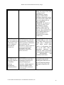
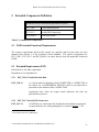
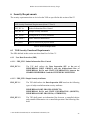
Belkin® Secure DVI-I KVM Switch Security Target EAL2 augmented ALC_FLR.3 Release Date: February 28, 2013 Document ID: 11-2098-R-0001 Version: 1.2 Prepared By: InfoGard Laboratories, Inc. Prepared For: Belkin International, Inc. 12045 E. Waterfront Drive Playa Vista, CA 90094 Belkin® Secure DVI KVM Switch Security Target Table of Contents INTRODUCTION AND DESCRIPTION ............................................................................................................................ 4 1.1 IDENTIFICATION ............................................................................................................................................... 4 1.2 OVERVIEW AND LOGICAL SCOPE ..................................................................................................................... 5 1.3 DOCUMENT CONVENTIONS .............................................................................................................................. 5 1.4 DOCUMENT TERMINOLOGY.............................................................................................................................. 6 1.4.1 ST Specific Terminology ........................................................................................................................ 6 1.4.2 Acronyms ............................................................................................................................................... 8 1.5 PROTECTION PROFILE OVERVIEW .................................................................................................................... 9 1.6 COMMON CRITERIA PRODUCT TYPE ................................................................................................................. 9 1.7 PHYSICAL BOUNDARIES ................................................................................................................................... 9 1.7.1 Evaluated Environment.......................................................................................................................... 9 1.7.2 Guidance Documents ........................................................................................................................... 12 1.8 ITEMS EXCLUDED FROM THE TOE ................................................................................................................. 12 2 CONFORMANCE CLAIMS .......................................................................................................................... 14 3 SECURITY PROBLEM DEFINITION ......................................................................................................... 15 3.1 SECURE USAGE ASSUMPTIONS ....................................................................................................................... 15 3.2 THREATS ........................................................................................................................................................ 15 3.3 ORGANIZATIONAL SECURITY POLICIES .......................................................................................................... 16 4 SECURITY OBJECTIVES ............................................................................................................................. 17 4.1 4.2 4.3 4.4 4.5 4.6 5 SECURITY OBJECTIVES FOR THE TOE ........................................................................................................... 17 SECURITY OBJECTIVES FOR THE OPERATIONAL ENVIRONMENT..................................................................... 18 MAPPING OF SECURITY ENVIRONMENT TO SECURITY OBJECTIVES ................................................................ 18 SECURITY OBJECTIVES RATIONALE ............................................................................................................... 19 SECURITY OBJECTIVES RATIONALE FOR THE OPERATIONAL ENVIRONMENT ................................................. 23 RATIONALE FOR ORGANIZATIONAL POLICY COVERAGE................................................................................ 23 EXTENDED COMPONENTS DEFINITION ............................................................................................... 24 5.1 TOE EXTENDED FUNCTIONAL REQUIREMENTS ............................................................................................. 24 5.2 EXTENDED REQUIREMENTS (EXT) ................................................................................................................ 24 5.2.1 EXT_VIR.1 Visual Indication Rule ...................................................................................................... 24 5.2.2 EXT_IUC.1 Invalid USB Connection .................................................................................................. 24 5.2.3 EXT_ROM.1 Read-Only ROMs ........................................................................................................... 25 5.3 RATIONALE FOR EXPLICITLY STATED SECURITY REQUIREMENTS ................................................................. 25 6 SECURITY REQUIREMENTS ..................................................................................................................... 26 6.1 TOE SECURITY FUNCTIONAL REQUIREMENTS ............................................................................................... 26 6.1.1 User Data Protection (FDP) ............................................................................................................... 26 6.1.2 Security Management (FMT) ............................................................................................................... 27 6.1.3 Protection of the TSF (FPT) ................................................................................................................ 28 6.2 RATIONALE FOR TOE SECURITY REQUIREMENTS ......................................................................................... 28 6.2.1 TOE Security Functional Requirements Tracing & Rationale ............................................................ 28 6.3 RATIONALE FOR IT SECURITY REQUIREMENT DEPENDENCIES ...................................................................... 30 6.4 DEPENDENCIES NOT MET .............................................................................................................................. 31 6.5 SECURITY ASSURANCE MEASURES ................................................................................................................ 31 6.6 RATIONALE FOR SECURITY ASSURANCE ........................................................................................................ 32 7 TOE SUMMARY SPECIFICATION ............................................................................................................ 33 © 2011 Belkin® International, Inc. and InfoGard Laboratories, Inc. 2 Belkin® Secure DVI KVM Switch Security Target 7.1 7.2 7.3 7.4 7.5 7.6 USER DATA PROTECTION (FDP) .................................................................................................................... 33 SECURITY MANAGEMENT (FMT) ................................................................................................................... 33 PROTECTION OF THE TSF (FPT) ..................................................................................................................... 33 VISUAL INDICATION (EXT_VIR) ................................................................................................................... 33 USB CONNECTION (EXT_IUC) ..................................................................................................................... 34 READ-ONLY MEMORY (EXT_ROM) ............................................................................................................. 34 List of Tables Table 1: Evaluated TOE and Environment Components .............................................................. 12 Table 2: TOE Security Objectives ................................................................................................ 18 Table 3: Operational Environment Security Objectives ............................................................... 18 Table 4: Threats & IT Security Objectives Mappings .................................................................. 19 Table 5: Extended SFR Components ........................................................................................... 24 Table 6: Functional Requirements ................................................................................................ 26 Table 7: SFR and Security Objectives Mapping........................................................................... 28 Table 8 - Objective to SFRs Rationale ......................................................................................... 30 Table 9: SFR Dependencies .......................................................................................................... 31 Table 10: Security Assurance Measures ...................................................................................... 32 © 2011 Belkin® International, Inc. and InfoGard Laboratories, Inc. 3 Belkin® Secure DVI KVM Switch Security Target Introduction and Description This section identifies the Security Target (ST), Target of Evaluation (TOE), conformance claims, ST organization, document conventions, and terminology. It also includes an overview of the evaluated product. 1.1 Identification Belkin Secure 2-port DVI-I KVM w/audio Part Number F1DN102B <or> Belkin Secure 4-port DVI-I KVM w/audio Part Number F1DN104B <or> Belkin Secure 2-port DVI-I KVM w/audio Plus Part Number F1DN102C <or> Belkin Secure 4-port DVI-I KVM w/audio Plus Part Number F1DN104C <or> Belkin Secure 4-port DVI-I Dual-Head KVM w/audio Part Number F1DN104E <or> Belkin Secure 4-port DVI-I Dual-Head KVM w/audio Plus Part Number F1DN104F <or> Secure 8-port Single-head DVI-I (Dual Link) KVM w/ audio and user authentication port Part Number F1DN108C <or> Secure 8-port Dual-head DVI-I (Dual Link) KVM w/ audio and user authentication port Part Number F1DN108F <or> Secure 16-port Single-head DVI-I (Dual-Link) KVM w/ audio and user authentication port Part © 2011 Belkin® International, Inc. and InfoGard Laboratories, Inc. 4 Belkin® Secure DVI KVM Switch Security Target Number F1DN116C All are version 111111 ST Identification: Belkin® Secure DVI-I KVM Switch Security Target EAL2 augmented ALC_FLR.3 ST Version: 1.2 ST Publish Date: February 28, 2013 ST Author: Ryan Day and Marvin Byrd, InfoGard Laboratories, Inc. PP Identification: Validated Protection Profile - Peripheral Sharing Switch for Human Interface Devices Protection Profile, Version 2.1, September 7, 2010 1.2 Overview and Logical Scope The Belkin® Secure KVM is a hardware device used to share peripheral devices with multiple computers. The peripheral devices supported are a mouse, keyboard, video display, and audio output. The KVM device is designed and evaluated to assure that no interactions with one computer can be intercepted by another system, thereby providing secure sessions with one system at a time. The Belkin® Secure KVM (referred to as the TOE in this document) supports one method of user interaction. The front panel of the TOE supports manual push-button selections to invoke the functions of the TOE. The TOE includes all security functionality offered within the physical scope of the TOE, except the functionality described in section 1.8, ‘Items Excluded from the TOE’. 1.3 Document Conventions Words which appear in SMALL CAPITALS are those which are formally defined in the Document Terminology section. The CC defines four operations on security functional requirements. The conventions below define the conventions used in this ST to identify these operations. When NIAP interpretations are included in requirements, the additions from the interpretations are displayed as refinements. Assignment: indicated with bold text Selection: indicated with underlined text Refinement: additions indicated with bold text and italics deletions indicated with strike-through bold text and italics © 2011 Belkin® International, Inc. and InfoGard Laboratories, Inc. 5 Belkin® Secure DVI KVM Switch Security Target Iteration: indicated with typical CC requirement naming followed by a lower case letter for each iteration (e.g., FMT_MSA.1a) Extended: indicated as per the applicable PP (e.g. EXT_VIR.1) The explicitly stated requirements claimed in this ST are denoted by the “EXT” extension in the unique short name for the explicit security requirement. 1.4 Document Terminology Please refer to CC Part 1 Section 4 for definitions of commonly used CC terms. 1.4.1 ST Specific Terminology Authorized User A USER who has been granted permission to interact with the TOE and all of its CONNECTED PERIPHERALS. Peripheral Data Information, including [buffered] STATE INFORMATION, sent from or to a PERIPHERAL. Plug and Play. A standardized interface for the automatic recognition and installation of interface cards and devices on a PC. Computer A programmable machine. The two principal characteristics of a computer are: it responds to a specific set of instructions in a welldefined manner, and it can execute a prerecorded list of instructions (a software program). For the purposes of this document, any electronic DEVICE controlling the MONITOR, and accepting signals from the KEYBOARD and POINTING DEVICE (if any) will qualify. Examples of computers under this definition are IBM-class personal computers (and so-called clones), desktop workstations, and control console INTERFACES into “mainframe” computers. State Information The current or last known status or condition, of a process, transaction, or setting. “Maintaining state” means keeping track of such data over time. Switch A DEVICE permitting a single set of PERIPHERALS to be shared among two or more COMPUTERS. Synonymous with TOE in this document. Residual Data Any PERIPHERAL DATA stored in a SWITCH. Port An external socket for plugging in communications lines and/or PERIPHERALS. Pointing Device A DEVICE, which converts relative positioning motion from a human operator into positioning information on a MONITOR. Examples of Pointing Devices include a mouse, trackball, joystick, and touchpad. Peripheral Port Group (“Group”)/ Peripheral Port Group ID © 2011 Belkin® International, Inc. and InfoGard Laboratories, Inc. 6 Belkin® Secure DVI KVM Switch Security Target A collection of HUMAN INTERFACE DEVICE PORTS treated as a single entity by the SWITCH. There is one Group for the set of SHARED PERIPHERALS and one Group for each SWITCHED COMPUTER directly CONNECTED to the SWITCH. Each SWITCHED COMPUTER Group has a unique logical ID. The shared Group ID is the same as that of the SWITCHED COMPUTER Group currently selected by the SWITCH. Peripheral A DEVICE that is logically and electrically (or electromagnetically) CONNECTED to a COMPUTER, but normally mounted outside of the COMPUTER enclosure. MONITORS, KEYBOARDS, and POINTING DEVICES are all peripherals. Output Device Any machine capable of representing information from a COMPUTER. This includes display screens, printers, plotters, and synthesizers. Monitor A COMPUTER OUTPUT surface and projecting mechanism that show text and other graphic images from a COMPUTER system to a user, using a Cathode Ray Tube (CRT), Liquid Crystal Display (LCD), Light-Emitting Diode (LED), gas plasma, active matrix, or other image projection technology. The display (the terms display and monitor are often used interchangeably) is usually considered to include the screen or projection surface and the DEVICE that produces the information on the screen. In some COMPUTERS, the display is packaged in a separate unit called a monitor. Displays (and monitors) are also sometimes called Video Display Terminals (VDTs). Also included in this category are tactile braille OUTPUT DEVICES. Keyboard A DEVICE which converts the physical action of a USER such as the depressing of one or more buttons into electronic signals corresponding to the bitwise symbol for a character in some form of electronic alphabet. The most common example is the typewriter-like keyboard found on most home COMPUTERS, but the definition also includes braille keypads among other DEVICES. Interface The CONNECTION and interaction between hardware, software, and the USER. Input Device Any machine that feeds data into a COMPUTER. This includes scanners, touch screens, and voice response systems. Human Interface Devices Those PERIPHERALS which primarily allow a USER to directly observe and/or modify the operation/status of a COMPUTER. Examples include a keyboard, video MONITOR, mouse, and an optical head tracker. Modems, printers, hard drives, and scanners are not such devices. Device A unit of hardware, outside or inside the case or housing for the essential COMPUTER that is capable of providing INPUT to the essential COMPUTER or of receiving OUTPUT or both. The term PERIPHERAL is sometimes used as a synonym for device or any INPUT/OUTPUT unit. Attribute (See Peripheral Port Group ID) © 2011 Belkin® International, Inc. and InfoGard Laboratories, Inc. 7 Belkin® Secure DVI KVM Switch Security Target Connected A state in which information can be intentionally transferred. Connection A path for information flow between two or more DEVICES. Group (See Peripheral Port Group) Object (See Peripheral Data and State Information) Shared Peripheral (See Peripheral Port Group) Subject (See Peripheral Port Group) Switched Computer (See Peripheral Port Group) User The human operator of the TOE. 1.4.2 Acronyms CCIB CCIMB CM DVI EAL EEPROM FCC ID ISO ISSE ISSO IT KVM LCD LED MAC PP PSS SFP ST TOE TSC TSF TSP VDT Common Criteria Implementation Board Common Criteria Interpretations Management Board Configuration Management Digital Video Interface Evaluation Assurance Level Electrically Erasable Programmable Read-Only Memory Federal Communications Commission Identification International Standards Organization Information Systems Security Engineering Information Systems Security Organization Information Technology Keyboard-Video-Mouse Liquid Crystal Display Light-Emitting Diode Mandatory Access Control Protection Profile Peripheral Sharing Switch Security Function Policy Security Target Target of Evaluation TSF Scope of Control TOE Security Functions TOE Security Policy Video Display Terminal © 2011 Belkin® International, Inc. and InfoGard Laboratories, Inc. 8 Belkin® Secure DVI KVM Switch Security Target 1.5 Protection Profile Overview The Protection Profile specifies U.S. Department of Defense minimum security requirements for PERIPHERAL SWITCHES; DEVICES which enable a single set of HUMAN INTERFACE DEVICES to be shared between multiple COMPUTERS. The profile limits the use of Universal Serial Bus (USB) connections to keyboard, mouse, and display. No other USB device shall be valid. The Protection Profile is consistent with Common Criteria Version 3.1: Part 2, and Part 3 conformant (Evaluation Assurance Level 2 augmented with ALC_FLR.2). 1.6 Common Criteria Product type The TOE is a KVM switch device classified as a “Peripheral Switch” for Common Criteria. The TOE includes both hardware and firmware components. 1.7 Physical Boundaries This section lists the hardware and software components of the product and denotes which are in the TOE and which are in the environment. 1.7.1 Evaluated Environment This table identifies hardware components and indicates whether or not each component is in the TOE. © 2011 Belkin® International, Inc. and InfoGard Laboratories, Inc. 9 Belkin® Secure DVI KVM Switch Security Target TOE or Environment Component Description TOE Belkin Secure 2-port DVI-I KVM w/audio Part Number F1DN102B TOE Hardware <or> Belkin Secure 4-port DVI-I KVM w/audio Part Number F1DN104B <or> Belkin Secure 2-port DVI-I KVM w/audio Plus Part Number F1DN102C <or> Belkin Secure 4-port DVI-I KVM w/audio Plus Part Number F1DN104C <or> Belkin Secure 4-port DVI-I Dual-Head KVM w/audio Part Number F1DN104E <or> Belkin Secure 4-port DVI-I Dual-Head KVM w/audio Plus Part Number F1DN104F <or> Secure 8-port Single-head DVI-I (Dual Link) KVM w/ audio and user authentication port Part Number F1DN108C <or> Secure 8-port Dual-head DVI-I (Dual Link) KVM w/ audio and user authentication port Part Number F1DN108F <or> Secure 16-port Single-head DVI-I (Dual-Link) KVM w/ audio and user authentication port Part Number F1DN116C © 2011 Belkin® International, Inc. and InfoGard Laboratories, Inc. 10 Belkin® Secure DVI KVM Switch Security Target Environment USB or PS/2 Mouse and keyboard compatible with: Microsoft IntelliMouse Explorer 2.0 and 3.0 Logitech Comfort Mouse and Keyboard Dell USB mouse models: 0CJ3339, CU036 Dell Keyboard models: SK-8115, 0N242F, L100, TH826 Shared Peripheral Port Group Member Environment Monitor – DVI-I (video) DVI dual-link Monitors Shared Peripheral Port Group Member Including, but not limited to:Apple Cinema HD display 30-inch Environment Dell Widescreen 30-inch HP Widescreen (LP3065) 30-inch Gateway XHD3000 30-inch Samsung 30-inch (305T) Dell Ultra sharp 2007FP, 20” , Analog and Digital connections Dell Ultra sharp E190S, 19” , Analog and Digital connections Dell Ultra sharp E228WFP, Analog and Digital connections Samsung 2343BWX 23” , Analog and Digital connections Samsung SyncMaster 712n Analog only monitor Belkin DVI/USB KVM Cables (as needed): P/N Description F1D9012b06 DVI/USB/AUD SKVM CBL, DVI-D M/M; USB A/B, 6' F1D9012b10 DVI/USB/AUD SKVM CBL, DVI-D M/M; USB A/B, 10' F1D9012b15 DVI/USB/AUD SKVM CBL, DVI-D M/M; USB A/B, 15' F1D9013b06 CAC USB A/B SKVM CABLE, 6' F1D9013b10 CAC USB A/B SKVM CABLE, 10' F1D9013b15 CAC USB A/B SKVM CABLE, 15' F1D9014b06 DUAL DVI/USB/AUD SKVM CBL, DVI-D M/M; USB A/B, 6' F1D9014b10 DUAL DVI/USB/AUD SKVM CBL, DVI-D M/M; USB A/B, 10' F1D9014b15 DUAL DVI/USB/AUD SKVM CBL, DVI-D M/M; USB A/B, 15' F1D9015b06 DVI-A male to HD 15 VGA Male, 6', USB A/B F1D9015b10 DVI-A male to HD 15 VGA Male, 10', USB A/B © 2011 Belkin® International, Inc. and InfoGard Laboratories, Inc. Cables for connection of Host Computers to Peripheral Port Group 11 Belkin® Secure DVI KVM Switch Security Target Environment Environment Audio Device (Speakers: supports 3.5mm connector) Host Computers Qty 2, or 4, 8, or 16 based on KVM used Any hardware platform supporting the following Operating Systems: Windows 2000 Professional –service pack 4 MS Windows XP (Home/Pro) –service pack 3 MS Windows 2003 Server – latest released service pack MS Windows Vista – 32/64bit MS Windows 7 – 32/64bit Apple OS X v10.4 and higher Red Hat Linux Desktop – latest released version Red Hat Enterprise Linux WS – latest released version Ubuntu 9.10 Linux – latest released version Shared Peripheral Group Member Operational Environmen t Host Computer resources with USB HID support and single or dual DVI monitor output support. Table 1: Evaluated TOE and Environment Components 1.7.2 Guidance Documents The following guidance documents are provided with the TOE upon delivery in accordance with EAL 2 requirements: Document Name Version Belkin® Secure DVI‐I KVM Common Criteria Supplement 1.01 Belkin® Secure DVI‐I KVM Switch with Audio User Manual Document Number 8820‐00764 Rev. A00 Belkin® Secure DVI‐I KVM Dual‐Head Switch with Audio User Manual Document Number 8820‐00762 Rev. A00 All documentation delivered with the product is germane to and within the scope of the TOE. 1.8 Items Excluded from the TOE This section identifies any items that are specifically excluded from the TOE. CAC switching or User Authentication device switching o A tamper label will be applied to the CAC port during manufacturing, and © 2011 Belkin® International, Inc. and InfoGard Laboratories, Inc. 12 Belkin® Secure DVI KVM Switch Security Target removal will not be allowed per guidance. DCU (Desktop Controller Unit or Remote Control) o The use of the optional DCU is not allowed per guidance. © 2011 Belkin® International, Inc. and InfoGard Laboratories, Inc. 13 Belkin® Secure DVI KVM Switch Security Target 2 Conformance Claims The TOE is Common Criteria (CC) Version 3.1R3 Part 2 Extended. The TOE is Common Criteria (CC) Version 3.1R3 Part 3 conformant at EAL2 (+ALC_FLR.3). The TOE is compliant with all International interpretations with effective dates on or before TBD. This TOE is conformant to the following Protection Profile: Peripheral Sharing Switch (PSS) for Human Interface Devices. Assurance Level: EAL 2 augmented with ALC_FLR.2 PP Version: 2.1, 7 September 2010. As a result, the Security Target directly uses text from this Protection Profile. The ALC_FLR.2 requirement of the PP is met through ALC_FLR.3 conformance. © 2011 Belkin® International, Inc. and InfoGard Laboratories, Inc. 14 Belkin® Secure DVI KVM Switch Security Target 3 Security Problem Definition This section contains assumptions regarding the security environment and the intended usage of the TOE and threats on the TOE and the Operational Environment. 3.1 Secure Usage Assumptions A.ACCESS An AUTHORIZED USER possesses the necessary privileges to access the information transferred by the TOE. USERS are AUTHORIZED USERS. A.MANAGE The TOE is installed and managed in accordance with the manufacturer’s directions. A.NOEVIL The AUTHORIZED USER is non-hostile and follows all usage guidance. A.PHYSICAL The TOE is physically secure. 3.2 Threats The asset under attack is the information transiting the TOE. In general, the threat agent is most likely (but not limited to) people with TOE access (who are expected to possess “average” expertise, few resources, and moderate motivation) or failure of the TOE or PERIPHERALS. T.INVALIDUSB The AUTHORIZED USER will connect unauthorized USB devices to the peripheral switch. T.RESIDUAL RESIDUAL DATA may be transferred between PERIPHERAL PORT GROUPS with different IDs. T.ROM_PROG The TSF may be modified by an attacker such that code embedded in reprogrammable ROMs is overwritten, thus leading to a compromise of the separation-enforcing components of the code and subsequent compromise of the data flowing through the TOE. T.SPOOF Via intentional or unintentional actions, a USER may think the set of SHARED PERIPHERALS are CONNECTED to one COMPUTER when in fact they are connected to a different one. T.STATE STATE INFORMATION may be transferred an ID other than the selected one. T.TRANSFER A CONNECTION, via the TOE, between COMPUTERS may allow information transfer. T.PHYSICAL The TOE may be physically tampered or modified, allowing unauthorized information flows. © 2011 Belkin® International, Inc. and InfoGard Laboratories, Inc. to a PERIPHERAL PORT GROUP with 15 Belkin® Secure DVI KVM Switch Security Target 3.3 Organizational Security Policies There are no Organizational Security Policies for this TOE. © 2011 Belkin® International, Inc. and InfoGard Laboratories, Inc. 16 Belkin® Secure DVI KVM Switch Security Target 4 Security Objectives This chapter describes the security objectives for the TOE and the Operational Environment. The security objectives are divided between TOE Security Objectives (for example, security objectives addressed directly by the TOE) and Security Objectives for the Operating Environment (for example, security objectives addressed by the IT domain or by non-technical or procedural means). 4.1 Security Objectives For The TOE This section defines the IT security objectives that are to be addressed by the TOE. Security Objective Description O.CONF The TOE shall not violate the confidentiality of information which it processes. Information generated within any PERIPHERAL GROUP COMPUTER CONNECTION shall not be accessible by any other PERIPHERAL GROUP with a different GROUP ID. O.INDICATE The AUTHORIZED USER shall receive an unambiguous indication of which SWITCHED COMPUTER has been selected. O.ROM TOE software/firmware shall be protected against unauthorized modification. Embedded software must be contained in mask-programmed or one-time-programmable read-only memory permanently attached (nonsocketed) to a circuit assembly. O.SELECT An explicit action by the AUTHORIZED USER shall be used to select the COMPUTER to which the shared set of PERIPHERAL DEVICES is CONNECTED. O.SWITCH O.USBDETECT 1 Single push button, multiple push button, or rotary selection methods are used by most (if not all) current market products. Automatic switching based on scanning shall not be used as a selection mechanism All DEVICES in a SHARED PERIPHERAL GROUP shall be CONNECTED to at most one SWITCHED COMPUTER at a time. The TOE shall detect any USB connection that is not a pointing device, keyboard, or display1 and will perform no interaction with that device after the initial identification. The TOE does not allow USB displays. © 2011 Belkin® International, Inc. and InfoGard Laboratories, Inc. 17 Belkin® Secure DVI KVM Switch Security Target O.TAMPER The TOE Device provides unambiguous detection of physical tampering to determine whether physical tampering with the TSF's devices or TSF's enclosure has occurred. Table 2: TOE Security Objectives 4.2 Security Objectives for the Operational Environment The following IT security objectives for the environment are to be addressed by the Operational Environment by technical means. Environment Security Objective OE.ACCESS Description The AUTHORIZED USER shall possess the necessary privileges to access the information transferred by the TOE. USERS are AUTHORIZED USERS. OE.MANAGE The TOE shall be installed and managed in accordance with the manufacturer’s directions. OE.NOEVIL The AUTHORIZED USER shall be non-hostile and follow all usage guidance. OE.PHYSICAL The TOE shall be physically secure. Table 3: Operational Environment Security Objectives 4.3 Mapping of Security Environment to Security Objectives The following table represents a mapping of the threats and assumptions to the security objectives defined in this ST. © 2011 Belkin® International, Inc. and InfoGard Laboratories, Inc. 18 X T.INVALIDUSB X T.PHYSICAL T.RESIDUAL O.USBDETECT O.TAMPER O.SWITCH O.SELECT O.ROM O.INDICATE O.CONF Belkin® Secure DVI KVM Switch Security Target X X T.ROM_PROG T.SPOOF X T.STATE X T.TRANSFER X X X Table 4: Threats & IT Security Objectives Mappings 4.4 Security Objectives Rationale Threat Objective Rationale T.INVALIDUSB The AUTHORIZED USER will connect unauthorized USB devices to the peripheral switch. O.USBDETECT The TOE shall detect any USB connection that is not a pointing device, keyboard, or display2 and will perform no interaction with that device after the initial identification. O.USBDETECT will detect the unauthorized connection so that it information from it can be ignored. T.RESIDUAL RESIDUAL DATA may be transferred between PERIPHERAL PORT GROUPS with different IDs O.CONF The TOE shall not violate the confidentiality of information, which it processes. Information generated within any PERIPHERAL GROUP COMPUTER CONNECTION shall not be accessible by any other PERIPHERAL GROUP O.CONF: If the PERIPHERALS can be CONNECTED to more than one COMPUTER at any given instant, then a channel may exist which would allow transfer of information from one to the other. This is particularly important for 2 The TOE does not allow USB displays. © 2011 Belkin® International, Inc. and InfoGard Laboratories, Inc. 19 Belkin® Secure DVI KVM Switch Security Target with a different GROUP ID. T.ROM_PROG The TSF may be modified by an attacker such that code embedded in reprogrammable ROMs is overwritten, thus leading to a compromise of the separation-enforcing components of the code and subsequent compromise of the data flowing through the TOE. O.ROM TOE software/firmware shall be protected against unauthorized modification. Embedded software must be contained in mask-programmed or one-time-programmable read-only memory permanently attached (non-socketed) to a circuit assembly. © 2011 Belkin® International, Inc. and InfoGard Laboratories, Inc. DEVICES with bi-directional communications channels such as KEYBOARD and POINTING DEVICES. Since many PERIPHERALS now have embedded microprocessors or microcontrollers, significant amounts of information may be transferred from one COMPUTER system to another, resulting in compromise of sensitive information. An example of this is transfer via the buffering mechanism in many KEYBOARDS. Further, the purpose of the TOE is to share a set of PERIPHERALS among multiple COMPUTERS. Information transferred to/from one SWITCHED COMPUTER is not to be shared with any other COMPUTER The threat of software (firmware) embedded in reprogrammable ROMs is mitigated by ensuring that the ROMs used in the TSF to hold embedded TSF data are not physically able to be reprogrammed. Thus, even if an interface does exist to the ROM containing the embedded TSF code, high confidence can be obtained that that code (stored in the ROM) will remain unchanged. 20 Belkin® Secure DVI KVM Switch Security Target T.SPOOF Via intentional or unintentional actions, a USER may think the set of SHARED PERIPHERALS are CONNECTED to one COMPUTER when in fact they are connected to a different one. O.INDICATE The AUTHORIZED USER shall receive an unambiguous indication of which SWITCHED COMPUTER has been selected. O.SELECT An explicit action by the AUTHORIZED USER shall be used to select the COMPUTER to which the shared set of PERIPHERAL DEVICES is CONNECTED. Single push button, multiple push button, or rotary selection methods are used by most (if not all) current market products. Automatic switching based on scanning shall not be used as a selection mechanism. O.INDICATE: The USER must receive positive confirmation of SWITCHED COMPUTER selection. O.SELECT: The USER must take positive action to select the current SWITCHED COMPUTER T.TRANSFER A CONNECTION, via the TOE, between COMPUTERS may allow information transfer. O.CONF The TOE shall not violate the confidentiality of information, which it processes. Information generated within any PERIPHERAL GROUPCOMPUTER CONNECTION shall not be accessible by any other PERIPHERAL GROUPCOMPUTER CONNECTION. O.SWITCH All DEVICES in a SHARED PERIPHERAL GROUP shall be CONNECTED to at most one SWITCHED COMPUTER at a time. O.CONF: If the PERIPHERALS can be CONNECTED to more than one COMPUTER at any given instant, then a channel may exist which would allow transfer of information from one to the other. This is particularly important for DEVICES with bi-directional communications channels such as KEYBOARD and POINTING DEVICES. Since many PERIPHERALS now have embedded microprocessors or microcontrollers, significant amounts of information may be transferred from one COMPUTER system to another, resulting in compromise of sensitive information. An example of this is transfer via the buffering mechanism in many © 2011 Belkin® International, Inc. and InfoGard Laboratories, Inc. 21 Belkin® Secure DVI KVM Switch Security Target KEYBOARDS. Further, the purpose of the TOE is to share a set of PERIPHERALS among multiple COMPUTERS. Information transferred to/from one SWITCHED COMPUTER is not to be shared with any other COMPUTER O.SWITCH: The purpose of the TOE is to share a set of PERIPHERALS among multiple COMPUTERS. It makes no sense to have, for example, video CONNECTED to one COMPUTER while a POINTING DEVICE is CONNECTED to another COMPUTER O.CONF The TOE shall not violate the may be transferred to confidentiality of information a PERIPHERAL PORT which it processes. Information GROUP with an ID generated within any PERIPHERAL GROUP COMPUTER other than the CONNECTION shall not be selected one. accessible by any other T.STATE STATE INFORMATION PERIPHERAL GROUP with a different GROUP ID T.PHYSICAL The TOE may be physically tampered or modified, allowing unauthorized information flows. O.TAMPER The TOE Device provides unambiguous detection of physical tampering to determine whether physical tampering with the TSF's devices or TSF's enclosure has occurred. © 2011 Belkin® International, Inc. and InfoGard Laboratories, Inc. If the PERIPHERALS can be CONNECTED to more than one COMPUTER at any given instant, then a channel may exist which would allow transfer of information from one to the other. This is particularly important for DEVICES with bi-directional communications channels such as KEYBOARD and POINTING DEVICES. The TOE provides mechanisms that provide unambiguous indication of a physical tampering attempt that might compromise the TSF. 22 Belkin® Secure DVI KVM Switch Security Target 4.5 Security Objectives Rationale for the Operational Environment Assumption A.NOEVIL The AUTHORIZED USER is non-hostile and follows all usage guidance. A.ACCESS An AUTHORIZED USER possesses the necessary privileges to access the information transferred by the TOE. USERS are AUTHORIZED USERS. A.MANAGE The TOE is installed and managed in accordance with the manufacturer’s directions. A.PHYSICAL The TOE is physically secure. Environmental Objective Addressing the Assumption OE.NOEVIL The AUTHORIZED USER shall be non-hostile and follow all usage guidance. Rationale OE.ACCESS The AUTHORIZED USER shall possess the necessary privileges to access the information transferred by the TOE. USERS are AUTHORIZED USERS. OE.MANAGE The TOE shall be installed and managed in accordance with the manufacturer’s directions. OE.PHYSICAL The TOE shall be physically secure. All authorized users are trustworthy individuals, having background investigations commensurate with the level of data being protected, have undergone appropriate training, and follow all user guidance. Restates the assumption. Restates the assumption. The TOE is assumed to be protected from physical attack (e.g., theft, modification, destruction, or eavesdropping). Physical attack could include unauthorized intruders into the TOE environment, but it does not include physical destructive actions that might be taken by an individual that is authorized to access the TOE environment. 4.6 Rationale For Organizational Policy Coverage There are no Organizational Policies for this TOE. © 2011 Belkin® International, Inc. and InfoGard Laboratories, Inc. 23 Belkin® Secure DVI KVM Switch Security Target 5 Extended Components Definition Extended Security Functional Requirements (Explicit) EXT_VIR.1 Visual Indication Rule EXT_IUC.1 Invalid USB Connection EXT_ROM.1 Read-Only ROMs Table 5: Extended SFR Components 5.1 TOE Extended Functional Requirements The security requirements listed in this section are explicitly stated as they have not been obtained from Section 2 of the Common Criteria Standard. The explicit requirements for EXT_VIR.1, EXT_IUC.1 and EXT_ROM.1 are taken directly from the applicable Protection Profile. 5.2 Extended Requirements (EXT) Hierarchical to: No other components. Dependencies: No dependencies. 5.2.1 EXT_VIR.1 Visual Indication Rule EXT_VIR.1.1 A visual method of indicating which COMPUTER is CONNECTED to the shared set of PERIPHERAL DEVICES shall be provided that is persistent for the duration of the CONNECTION. Application Note: Does not require tactile indicators, but does not preclude their presence. 5.2.2 EXT_IUC.1 Invalid USB Connection EXT_IUC.1.1 3 All USB devices connected to the Peripheral switch shall be interrogated to ensure that they are valid (pointing device, keyboard, display3). No The TOE does not allow USB displays. © 2011 Belkin® International, Inc. and InfoGard Laboratories, Inc. 24 Belkin® Secure DVI KVM Switch Security Target further interaction with non-valid devices shall be performed. 5.2.3 EXT_ROM.1 Read-Only ROMs EXT_ROM.1.1 TSF software embedded in TSF ROMs must be contained in maskprogrammed or one-time-programmable read-only memory permanently attached (non-socketed) to a circuit assembly. 5.3 Rationale for Explicitly Stated Security Requirements These Explicit SFRs are from the applicable Protection Profile. © 2011 Belkin® International, Inc. and InfoGard Laboratories, Inc. 25 Belkin® Secure DVI KVM Switch Security Target 6 Security Requirements The security requirements that are levied on the TOE are specified in this section of the ST. TOE Security Functional Requirements (from CC Part 2) FDP_IFC.1a Subset Information Flow Control FDP_IFF.1a Simple Security Attributes FMT_MSA.1 Management of Security Attributes FMT_MSA.3 Static Attribute Initialisation FPT_PHP.1 Passive detection of physical attack Table 6: Functional Requirements 6.1 TOE Security Functional Requirements The SFRs defined in this section are taken from Part 2 of the CC. 6.1.1 User Data Protection (FDP) 6.1.1.1 FDP_IFC.1 Subset Information Flow Control FDP_IFC.1.1 The TSF shall enforce the Data Separation SFP on the set of PERIPHERAL PORT GROUPS, and the bi-directional flow of PERIPHERAL DATA and STATE INFORMATION between the SHARED PERIPHERALS and the SWITCHED COMPUTERS. 6.1.1.2 FDP_IFF.1 Simple Security Attributes FDP_IFF.1.1 The TSF shall enforce the Data Separation SFP based on the following types of subject and information security attributes: PERIPHERAL PORT GROUPS (SUBJECTS), PERIPHERAL DATA and STATE INFORMATION (OBJECTS), PERIPHERAL PORT GROUP IDs (ATTRIBUTES). FDP_IFF.1.2 The TSF shall permit an information flow between a controlled subject and controlled information via a controlled operation if the following rules hold: © 2011 Belkin® International, Inc. and InfoGard Laboratories, Inc. 26 Belkin® Secure DVI KVM Switch Security Target Switching Rule: PERIPHERAL DATA can flow to a PERIPHERAL PORT GROUP with a given ID only if it was received from a PERIPHERAL PORT GROUP with the same ID. FDP_IFF.1.3 The TSF shall enforce the No additional information flow control SFP rules. FDP_IFF.1.4 The TSF shall provide the following: No additional SFP capabilities. FDP_IFF.1.5 The TSF shall explicitly authorize an information flow based on the following rules: No additional rules. FDP_IFF.1.6 The TSF shall explicitly deny an information flow based on the following rules: No additional rules. 6.1.2 Security Management (FMT) 6.1.2.1 FMT_MSA.1 Management of Security Attributes FMT_MSA.1.1 The TSF shall enforce the Data Separation SFP to restrict the ability to modify the security attributes PERIPHERAL PORT GROUP IDs to the USER. Application Note: An AUTHORIZED USER shall perform an explicit action to select the COMPUTER to which the shared set of PERIPHERAL devices is CONNECTED, thus effectively modifying the GROUP IDs associated with the PERIPHERAL DEVICES. 6.1.2.2 FMT_MSA.3 Static Attribute Initialization FMT_MSA.3.1 The TSF shall enforce the Data Separation SFP to provide restrictive default values for security attributes that are used to enforce the SFP. Application Note: On start-up, one and only one attached COMPUTER shall be selected. FMT_MSA.3.2 The TSF shall allow the None to specify alternative initial values to override the default values when an object or information is created. © 2011 Belkin® International, Inc. and InfoGard Laboratories, Inc. 27 Belkin® Secure DVI KVM Switch Security Target 6.1.3 Protection of the TSF (FPT) 6.1.3.1 FPT_PHP.1 Passive detection of physical attack FPT_PHP.1.1 The TSF shall provide unambiguous detection of physical tampering that might compromise the TSF. FPT_PHP.1.2 The TSF shall provide the capability to determine whether physical tampering with the TSF's devices or TSF's elements has occurred. 6.2 Rationale For TOE Security Requirements The section below demonstrates the tracing of Security Functional Requirements to Security Objectives and describes the applicable rationale based on direct reference from the applicable Protection Profile. FDP_IFC.1 X FDP_IFF.1 X O.USBDETECT O.TAMPER X FMT_MSA.1 X FMT_MSA.3 X X FPT_PHP.1 X EXT_ROM.1 EXT_VIR.1 O.SWITCH O.ROM O.SELECT O.INDICATE TOE Security Functional Requirements Tracing & Rationale O.CONF 6.2.1 X EXT_IUC.1 X Table 7: SFR and Security Objectives Mapping © 2011 Belkin® International, Inc. and InfoGard Laboratories, Inc. 28 Belkin® Secure DVI KVM Switch Security Target Objective O.CONF The TOE shall not violate the confidentiality of information, which it processes. Information generated within any PERIPHERAL GROUPCOMPUTER CONNECTION shall not be accessible by any other PERIPHERAL GROUPCOMPUTER CONNECTION O.INDICATE The AUTHORIZED USER shall receive an unambiguous indication of which SWITCHED COMPUTER has been selected Requirements Addressing the Objective FDP_IFC.1 (Subset Information Flow Control) FDP_IFF.1 (Simple Security Attributes) EXT_VIR.1 (Visual Indication Rule) O.ROM TOE software/firmware shall be protected against unauthorized modification. Embedded software must be contained in maskprogrammed or one-timeprogrammable read-only memory permanently attached (non-socketed) to a circuit assembly. EXT_ROM.1 (Read-Only ROMs) O.SELECT An explicit action by the AUTHORIZED USER shall be used to select the COMPUTER to which the shared set of PERIPHERAL DEVICES is CONNECTED. Single push button, multiple push button, FMT_MSA.1 (Management of Security Attributes) FMT_MSA.3 (Static Attribute Initialization) © 2011 Belkin® International, Inc. and InfoGard Laboratories, Inc. Rationale FDP_IFC.1: This captures the policy that no information flows between different PERIPHERAL PORT GROUP IDS. FDP_IFF.1: This requirement identifies the security ATTRIBUTES needed to detail the operation of a switch and the rules allowing information transfer. This requirement is a dependency of FDP_IFC.1. EXT_VIR.1: There must be some positive feedback from the TOE to the USER to indicate which SWITCHED COMPUTER is currently CONNECTED. Part 2 of the Common Criteria does not provide a component appropriate to express the requirement for visual indication. EXT_ROM.1 implements the O.ROM objective directly. While there might be other ways to protect embedded TSF code on a ROM (programmable or not), the requirement stipulates an easilyverifiable implementation that ensures that the TSF code will not be overwritten or modified. FMT_MSA.1: This restricts the ability to change selected PERIPHERAL PORT GROUP IDS to the AUTHORIZED USER. This requirement is a dependency of FMT_MSA.3. FMT_MSA.3: The TOE assumes a default PERIPHERAL 29 Belkin® Secure DVI KVM Switch Security Target or rotary selection methods are used by most (if not all) current market products. Automatic switching based on scanning shall not be used as a selection mechanism. O.SWITCH All DEVICES in a SHARED PERIPHERAL GROUP shall be CONNECTED to at most one SWITCHED COMPUTER at a time. O.USBDETECT The TOE shall detect any USB connection that is not a pointing device, keyboard, or display4 and disable that connection. O.TAMPER The TOE Device provides unambiguous detection of physical tampering to determine whether physical tampering with the TSF's devices or TSF's enclosure has occurred. PORT GROUP selection FDP_IFF.1 (Simple Security Attributes) EXT_IUC.1 (invalid USB Connection) FPT_PHP.1 (Passive detection of physical attack) based on a physical switch position or a manufacturer’s specified sequence for choosing among the CONNECTED COMPUTERS (CONNECTED here implies powered on). This requirement is a dependency of FDP_IFF.1 and FDP_ITC.1. FDP_IFF.1: This requirement identifies the security ATTRIBUTES needed to detail the operation of a switch and the rules allowing information transfer. This requirement is a dependency of FDP_IFC.1. EXT_IUC.1: Upon detection of an invalid USB connection, the switch will disable the connection and notify the user. FPT_PHP.1: The TOE is required to provide unambiguous detection of any potential physical modification or unauthorized internal access to the TOE Table 8 - Objective to SFRs Rationale 6.3 Rationale For IT Security Requirement Dependencies This section includes a table of all the security functional requirements and their dependencies and a rationale for any dependencies that are not satisfied. 4 The TOE does not allow USB displays. © 2011 Belkin® International, Inc. and InfoGard Laboratories, Inc. 30 Belkin® Secure DVI KVM Switch Security Target Functional Component Dependency Included FDP_IFC.1 FDP_IFF.1 Simple security attributes Yes FDP_IFC.1 Subset information flow control Yes FMT_MSA.3 Static attribute initialisation Yes FDP_IFC.1 Subset information flow control Yes FMT_SMF.1 Specification of management functions No FMT_SMR.1 Security roles No FMT_MSA.1 Management of security attributes Yes FMT_SMR.1 Security roles No FPT_PHP.1 None None EXT_ROM.1 None None EXT_VIR.1 None None EXT_IUC.1 None None FDP_IFF.1 FMT_MSA.1 FMT_MSA.3 Table 9: SFR Dependencies 6.4 Dependencies Not Met FMT_SMR.1 (Security Roles) dependency of FMT_MSA.1 and FMT_MSA.3 FMT_SMF.1 (Specification of Management Functions) dependency of FMT_MSA.1 The TOE is not required to associate USERS with roles; hence, there is only one “role”, that of USER. This deleted requirement, a dependency of FMT_MSA.1 and FMT_MSA.3, allows the TOE to operate normally in the absence of any formal roles. The TOE does not offer any management capabilities. 6.5 Security Assurance Measures The assurance measures provided for this Security Target are described in detail in evidence documentation to be provided to the evaluation team during the course of the evaluation of this TOE. Evaluation activities of the Security Target are not included, as they are performed before officially entering evaluation. © 2011 Belkin® International, Inc. and InfoGard Laboratories, Inc. 31 Belkin® Secure DVI KVM Switch Security Target Assurance Class Assurance components ADV: Development ADV_ARC.1 Security architecture description ADV_FSP.2 Security-enforcing functional specification ADV_TDS.1 Basic design AGD: Guidance documents AGD_OPE.1 Operational user guidance AGD_PRE.1 Preparative procedures ALC: Life-cycle support ALC_CMC.2 Use of a CM system ALC_CMS.2 Parts of the TOE CM coverage ALC_DEL.1 Delivery procedures ALC_FLR.3 Systematic Flaw Remediation ATE: Tests ATE_COV.1 Evidence of coverage ATE_FUN.1 Functional testing ATE_IND.2 Independent testing - sample AVA: Vulnerability assessment AVA_VAN.2 Vulnerability analysis Table 10: Security Assurance Measures 6.6 Rationale for Security Assurance EAL 2 + ALC_FLR.3 was chosen to provide a moderate level of independently assured security. The chosen assurance level is consistent with the threat environment. Specifically, that the threat of malicious attacks is not greater than basic and the product will have undergone a search for obvious flaws. The assurance security requirements for this Security Target are taken from Part 3 of the CC. These assurance requirements compose an Evaluation Assurance Level 2 as defined by the CC. © 2011 Belkin® International, Inc. and InfoGard Laboratories, Inc. 32 Belkin® Secure DVI KVM Switch Security Target 7 TOE Summary Specification 7.1 User Data Protection (FDP) The TOE will only allow PERIPHERAL DATA and STATE INFORMATION to flow from the PERIPHERAL PORT GROUP to one COMPUTER at a time based on the ID selected at a given time. This is implemented through the switching mechanism of the TOE. The TOE contains two separate switching modules; Audio, and HID-display modules. Both modules are managed by the controller. The controller receives inputs from the front panel and invokes state changes to each module, as needed. Unidirectional optical diodes are used in the PERIPHERAL PORT GROUP traffic. This information can only flow out to the COMPUTERs, removing the ability of COMPUTERS to interact with the TOE. This means that the only inputs the TOE acts upon are from the front panel. The TOE modules are unable to connect to multiple COMPUTERS simultaneously. The logic within each module is coded so that this is not possible. The controller module is programmed to implement the switching of the PERIPHERAL PORT GROUP to COMPUTERS as described herein. This logic is programmed into one-time-programmable memory that is physically protected. 7.2 Security Management (FMT) The TOE only accepts inputs from the AUTHORIZED USER to perform any switching through the front panel switching commands (push buttons). The TOE does not read any data passing through it (PERIPHERAL DATA). No interfaces are available for any PERIPHERAL DATA to use to control the TOE. The PERIPHERAL PORT GROUP is connected to COMPUTER #1 by default upon completion of the self-check. This cannot be modified. 7.3 Protection of the TSF (FPT) The TOE includes two tamper sensors. When activated, the sensor signals the controller to enter into a permanent tamper state, thereby disabling the TOE. The TOE will only flash all LEDs, indicating an error state. While the TOE is in the error state, the user is unable to pass any information through the TOE to any COMPUTER, requiring replacement of the TOE. This ensures that security is always maintained in the event of a physical attack. 7.4 Visual Indication (EXT_VIR) The front panel of the TOE is the only way to select a different COMPUTER. This requires the USER manually press a button corresponding to the desired COMPUTER and PERIPHERAL PORT GROUP ID. Once the COMPTER has been selected, an LED adjacent to the button selected will illuminate. This LED remains illuminated while the connection is maintained. Once the user selects another COMPUTER (by depressing a different button), the original LED © 2011 Belkin® International, Inc. and InfoGard Laboratories, Inc. 33 Belkin® Secure DVI KVM Switch Security Target will darken and the LED corresponding to the new COMPUTER will illuminate. 7.5 USB Connection (EXT_IUC) When a peripheral device is inserted into the TOE, or the TOE is initialized, the TOE will query the device for its USB class. In the case of Human Interface devices (HIDs), the TOE will only communicate with devices claiming a class of “03h” corresponding to the HID USB class. 7.6 Read-Only Memory (EXT_ROM) The memory of the TOE is a form of ROM. The flash memory located within the microcontroller includes industry-standard lock bits. These bits signal the controller to not allow any writing to the flash memory. These lock bits can only be modified through using an internal JTAG interface, which is disabled near the end of production. These protections are not able to be bypassed without having physical access to the system board. The anti-tamper system described in section 7.3 assures that undetected internal access is not possible. © 2011 Belkin® International, Inc. and InfoGard Laboratories, Inc. 34