1
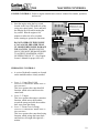
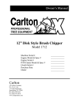
Model 7500
Machine Serial #
Engine Model & Spec #
Engine Serial #
Purchase Date
Dealer
Carlton
J.P.Carlton Company
Div. D.A.F. Inc.
121 John Dodd Road
Spartanburg, SC 29303
Ph. (864) 578-9335
Fax (864) 578-0210
www.stumpcutters.com
_____________
_____________
_____________
_____________
_____________
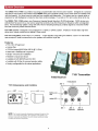
DIESEL ENGINE EXHAUST WARNING
CALIFORNIA
Proposition 65 Warning
Diesel engine exhaust and some of its constituents are
known to the State of California to cause cancer, birth
defects, and other reproduction harm.
7500
SAFETY ALERT
7500
SAFETY ALERT
7500
SAFETY ALERT
7500
SAFETY ALERT
7500
SAFETY ALERT
STUMP GRINDER LIMITED WARRANTY
J.P. Carlton Co. Inc., hereafter referred to as the “Manufacturer”, warrants each new Carlton Grinder to be free of
defects in workmanship and material for a period of one year.
This warranty takes effect upon delivery to the original retail purchaser. The manufacturer, at its option, will replace
or repair, at a point designated by the manufacturer, any parts which appear to have been defective in material or
workmanship. The manufacturer is not responsible for consequential damages.
This warranty will not apply if the grinder is not operated in a manner recommended by the manufacturer. The
following examples would void warranty:
1.
2.
3.
4.
The grinder has been abused.
The machine is involved in or damaged by an accident.
Repairs or attempted repairs were made without prior written authorization.
Including but not limited to repairs made due to normal wear.
The owner is responsible for all regular maintenance as explained in the operators’ manual. Neglect in regular
maintenance or failure to replace normal wear items such as teeth, pockets, lubrication oils, filters, belts, bearings,
etc. may void warranty.
This warranty is expressly in lieu of any other warranties, expressed or implied, including any implied warranty or
merchantability of fitness for a particular purpose and of any non-contractual liabilities including product liabilities
based upon negligence or strict liability. J.P. Carlton Co. Inc. will not be liable for consequential damages resulting
from breach of warranty.
IT IS NECESSARY TO RETURN THE WARRANTY VALIDATION FORM AND NOTIFY J.P. CARLTON
CO. INC. IN WRITING WITHIN TEN (10) DAYS FROM DELIVERY DATE TO VALIDATE THIS
WARRANTY.
NOTE: This warranty applies only to new and unused equipment or parts thereof manufactured by J.P. Carlton Co.
Inc. ANY MACHINES USED FOR LEASE OR RENTAL - WARRANTY IS LIMITED TO 90 DAYS FROM
FIRST DAY OF INITIAL SERVICE.
NOTICE: All power units and associated components are NOT warranted by J.P. Carlton Co. Inc. or their
dealers. It is the customers’ responsibility to return machine to the local engine distributor.
INFORMATION PHONE NUMBERS TO FIND YOUR LOCAL ENGINE & PARTS SERVICE CENTERS:
Honda ............................................ 1-770-497-6400 (GA-Eastern Time Zone)
Kohler Engines.............................. 1-800-544-2444 (Toll Free)
Briggs & Stratton Engines ........... 1-800-233-3723 (Toll Free)
Lombardini ................................... 1-770-623-3554 (GA-Eastern Time Zone)
Deutz Engines................................ 1-800-241-9886 (Toll Free)
John Deere Engines ...................... 1-800-533-6446 (Toll Free)
Caterpillar ..................................... 1-877-636-7658 (Toll Free)
Kubota ........................................... 1-847-955-2500 (IL-Central Time Zone)
Kawasaki Engines......................... 1-616-949-6500 (MI-Eastern Time Zone)
Wisconsin Engines ........................ 1-800-932-2858 (Toll Free)
Onan Engine ................................. 1-800-888-6626 (Toll Free)
In order to process any warranty claims, it is the owners’ responsibility to report claims promptly to us or our
authorized dealer from whom the equipment was purchased. It is necessary to include the following information on
any and all request for warranty:
1.
2.
3.
4.
Dealer from whom purchased
Date of delivery
Serial number of unit
Model number of unit
5.
6.
7.
8.
Engine make and serial number
Length of time in use
Date of failure
Nature of failure
STUMP GRINDER LIMITED WARRANTY
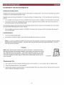
EXPLANATION OF LIMITED WARRANTY
The manufacturer will not reimburse the customer or dealer labor cost incurred for
installing “bolt-on” or “slip-on” items, such as pumps and motors, bearings, belts,
pulleys, etc. The manufacturer will provide replacement parts at no cost to the
customer for defective parts during the warranty period. Defective parts must be
returned to J.P. Carlton Company. It will be the customers’ responsibility to install
the replacement parts unless arrangements are made with the selling dealer.
The manufacturer will not reimburse travel cost to servicing dealer. It is the
customers’ responsibility to deliver machine to dealers facility, unless other
arrangements have been agreed to between the selling dealer and the customer.
The manufacturer may elect, at its discretion, to reimburse reasonable labor cost to
customer or dealer for major defect repairs. Prior approval must be obtained from
J.P. Carlton Company Inc.
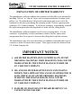
IMPORTANT NOTICE
1. AIR FILTER MAINTENANCE IS CRITICAL ON STUMP
GRINDING MACHINES. DIRT INGESTION WILL NOT BE
WARRANTED BY THE ENGINE MANUFACTURER OR
J.P. CARLTON COMPANY.
2. OIL AND OIL FILTER MAINTENANCE AND STAYING
WITHIN THE LIMITS OF THE ANGLE OF OPERATION IS
ALSO CRITICAL ON STUMP GRINDING MACHINES.
STARVING THE ENGINE FOR OIL WILL NOT BE
WARRANTED BY THE ENGINE MANUFACTURER OR
J.P. CARLTON COMPANY.
3. FAILURE TO MAINTAIN OUTBOARD BEARING CAN
CAUSE ENGINE FAILURE.
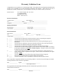
Warranty Validation Form
Congratulations on your purchase of a Carlton Stump Grinder. This product has been designed and manufactured to
provide years of profitable service while minimizing maintenance and downtime. Please take the time now to
complete this warranty validation form. This information is necessary for Carlton to instate your warranty.
Return Form To:
J.P. Carlton Company, Div. D.A.F. Inc.
121 John Dodd Road
Spartanburg, SC 29303
Phone: 1-864-578-9335
Purchaser Information:
Company Name:_______________________ Street Address:_____________________________
City:_________________________ State:__________ Zip Code:__________________________
Telephone:_______________________Contact:________________________________________
Machine Information:
Model Number :_______________________
Serial Number :________________________
Engine Model :________________________
Serial Number :________________________
Dealer Information:
Dealer Name:____________________ Street Address:___________________________
City: _______________________
State:__________
Zip Code:____________________
Contact Name: ____________________
1.
2.
3.
______
______
______
4.
5.
6.
7.
______
______
______
______
8.
______
9. ______
10. ______
11. ______
Customer has been instructed on operation and safety aspects of operating the equipment.
Customer has been advised not to reach into cutter wheel area.
Customer has been advised to stop machine and remove key before performing any type of
maintenance.
Customer has been warned not to operate the machine without the cutter wheel guard in place.
Customer has been furnished with all parts and operators manuals.
Customer has been instructed on equipment maintenance schedules and procedures.
Customer has been advise that the engine or power unit that is used on this machine is warranted
by the engine manufacturer and NOT J.P. Carlton Company. All engine warranty issues should
be addressed to the local engine dealer.
Customer understands the importance of air and oil filter maintenance, and the importance of
staying within the angle of operation of the engine. If either of these is not adhered to, the engine
warranty is VOID.
Customer understands to keep locking collars tight and purge bearings with grease.
All operation and warning decals are properly displayed on equipment.
Customer understands it is his responsibility to train all operators on operator safety.
I have inspected this equipment and find it in good working condition. To the best of my knowledge, the customer
and his personnel are aware of the above procedures.
Date: _______________
Signed: ____________________________________
Dealer Representative
The equipment has been thoroughly checked by the above named dealer representative, and I am
satisfied with his instructions.
Date: ________________
Signed: ___________________________________
Purchaser
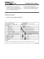
7500
TABLE OF CONTENTS
INTRODUCTION
FOREWORD
1
GENERAL INFORMATION
2
MACHINE FEATURES
3
MACHINE SPECIFICATIONS
4
OPERATION
SAFETY PRECAUTIONS
6
DAILY CHECKLIST
9
MACHINE CONTROLS
10
TOWING
17
MACHINE OPERATION
18
MAINTENANCE
MACHINE MAINTENANCE
22
LUBRICATION CHART
27
TROUBLESHOOTING GUIDE
28
MACHINE WIRING
30
LIGHTS & BRAKES ASSEMBLY
34
SERVICING CUTTER WHEEL
37
SERVICING HYDRAULICS
42
SERVICING BOOM PIVOT
44
SERVICING BELTS
45
SERVICING BEARINGS
53
SERVICING STUB SHAFT
62
HYDRAULIC ASSEMBLY
67
FRAME ASSEMBLY
76
PIVOT ASSEMBLY
82
ENGINE ASSEMBLY
84
ENGINE BELT ASSEMBLY
85
JACK SHAFT ASSEMBLY
87
POLY CHAIN® BELT ASSEMBLY
88
CUTTER WHEEL ASSEMBLY
89
PARTS
BACK
RADIO CONTROL MANUAL
7500
FOREWORD
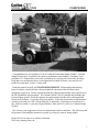
Congratulations on your purchase of a new Carlton® Professional Stump Grinder! Carlton®
Stump Grinders have a reputation for superior performance and reliability. A machine is not
profitable if it’s broken-down and we do our absolute best to help you avoid costly downtime.
Each and every machine has been over designed and overbuilt to ensure years and years of
trouble-free operation. In this, we take pride.
Read this manual carefully and TAKE RESPONSIBILITY for thoroughly familiarizing
yourself with the controls and the concepts behind the operation of this machine before
attempting to operate it. Slowly experiment with the controls and gradually work yourself up to
the full capabilities of this machine. The Carlton® Model 7500 is a durable and profitable professional stump grinder. Read this manual, the engine manual and the safety and operational
decals on the machine. Use proper safety precautions. Follow the instructions provided and use
common sense and your "OX" will perform like its namesake. If getting more work done in a
day, with less trouble, is your idea of good business, then you'll love your new Carlton® Stump
Grinder!
We welcome your suggestions on how we might better build our machines. We solicit any and
all questions concerning the operation or proper servicing of your new stump grinder.
Please feel free to write to us with any comments.
We'll enjoy hearing from you!
1
7500
GENERAL INFORMATION
The J. P. Carlton Company constantly strives to create the best equipment available in the stump
cutting industry. Therefore, the material in this manual is correct at the time of publication.
Carlton® reserves the right to make improvements, modifications and even discontinue features,
as we deem necessary to meet our goal. Carlton® also reserves the right to discontinue models
without any prior notification or obligation.
Inspect your new Carlton® Stump Grinder as soon as you receive it. Any damages incurred
during shipment are not warranted and therefore not covered repairs. You should have the truck
driver verify or acknowledge any damages caused during shipment. If not, contact the truck
lines as soon as possible with your complaint.
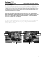
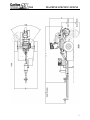
Any reference made to right, left, front or rear in relationship to the stump cutter is illustrated in
the following picture. Please refer to these any time you call your dealer or J. P. Carlton
Company for parts or assistance.
Front
Rear
Left
Front
Right
2
7500
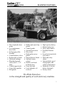
• Direct hydraulic drive
pump.
• Low maintenance
drive belts.
• Self-purging roller
bearings.
• Counterbalance valves.
• Replaceable rod ends.
• Hardened bushings.
• Blanchard ground
cutter wheel - 1 1/2"
thick.
• Carbide tipped teeth.
• Center lube spindles.
• Belt guards.
MACHINE FEATURES
• Rubber and metal chip
guards.
• Control guards.
• Optional hour meter.
• Key switch.
• High quality epoxy
primer.
• Dupont Imron® finish.
• Optional remote
control.
• Double wire braid
hydraulic hose.
• Large fuel tank.
• Large hydraulic oil
reservoir.
•
•
•
•
•
•
•
•
•
High capacity battery.
Marine battery box.
Heavy plate fenders.
Premium flotation
tires.
Swivel jack stand with
steel wheel.
Hitch and safety
chains.
Optional shake proof
towing lights with
coiled wiring harness.
Hydraulic or electric
brakes (Optional).
Factory tested.
We Pride Ourselves
in the strength and quality of each and every machine
3
7500
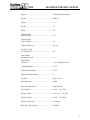
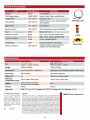
MACHINE SPECIFICATIONS
Engine .................................................................. 78 HP Turbo Deutz Diesel
Weight.................................................................. 4400 lbs.
Length .................................................................. 13’ 3”
Height .................................................................. 75”
Width ................................................................... 80”
Cutting Depth
Below Ground...................................................... 24”
Cutting Height
Above Ground...................................................... 46”
Cutter Head Swing............................................... 92” arc
Number of Teeth
on Cutter Wheel ................................................... 48
Cutter Wheel
Diameter W/Teeth................................................ 31”
Cutter Wheel
Thickness ............................................................. 1 1/2” Blanchard Ground
Jackshaft Bearings ............................................... 2 7/16”
Cutter Wheel Bearings......................................... 2 7/16”
Engine Stub Shaft Bearing................................... 2”
Tire Size............................................................... 8 Ply 9.5-16.5
Engine Belt Size................................................... 6B103
Poly Chain® Belt Size......................................... 14M-2380-68
Lift Cylinder ........................................................ 4”x12” - 1 3/4” Rod
Swing Cylinder .................................................... 3 1/2”x8” - 1 1/2” Rod
Tongue Cylinder .................................................. 3”x60” - 1 1/2” Rod
Fuel Tank Capacity .............................................. 25 Gallons
Hydraulic Tank Capacity ..................................... 4 Gallons
4
7500
MACHINE SPECIFICATIONS
5
7500
SAFETY PRECAUTIONS
Before operating the stump cutter, read this manual, the engine manual, and all the safety
decals on the machine. Know all parts of the machine and their functions, especially the
shut down procedures in case of emergency. No inexperienced person may operate
machine. Inexperience may cause injury.
SAFETY FIRST ALWAYS!
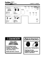
This is the Safety-Alert Symbol. This symbol is placed on the machine and in the
manual to alert the operator to the potential for bodily injury or death. The operator
should pay close attention to the instructions whenever they see this symbol.
The Safety-Alert Symbol will be accompanied by one of the following words:
DANGER, WARNING, or CAUTION
•
•
•
A DANGER symbol means that if the instructions are not followed the possibility of
serious personal injury or death is probable.
A WARNING symbol means that if the instructions are not followed there is a
possibility of serious personal injury or death.
A CAUTION symbol means there is an unsafe condition or practice that may cause
personal injury or property damage.
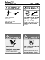
PERSONAL PROTECTION:
Wear face shield and hearing
protection
Do not wear loose-fitting
clothing
Tie back long hair
Do not wear jewelry
Keep clear of cutter wheel
Keep away from moving parts
Only operate in a well ventilated
area because of carbon monoxide
P/N 0700008
P/N 0700010
P/N 0700027
6
7500
SAFETY PRECAUTIONS
Be Safe and Practice Safe Operation using the following guidelines.
•
•
•
•
•
•
•
•
•
•
•
•
•
•
•
•
•
Any individual operating this machine must first read and
understand this manual, the engine manual, all component
manuals, and all safety decals on machine.
DO NOT permit children to operate machinery or to play
near machinery during operation.
Always wear face shield and hearing protection during
operation. Loud noise and flying debris may cause severe
injury.
Keep hands, feet, legs, clothing, hair and all other body
parts away from cutter wheel and other moving machine
parts to eliminate the possibility of injury.
Shut down machine completely and remove key before
removing debris from work area (i.e. clearing rocks, wood
chips, etc.).
DO NOT modify or change any part without written
approval from J. P. Carlton Company.
Do not ride, sit, stand, lay or climb anywhere on this
machine during operation, while running, or during
transport.
Do not move, position, or transport this machine while
cutter wheel is engaged.
DO NOT operate any machinery while under the influence
of alcohol or drugs (prescription, over the counter, or
otherwise).
Do not refill fuel tank while engine is hot, running, or
indoors. Danger of fire or explosion exists.
Fuel and its vapors are highly flammable and explosive.
Handle with care. Only use approved (red) fuel containers
for storage.
Do not store fuel containers near any open flames, sparks or
other sources of ignition.
Do not store equipment with fuel in the tank.
Battery fumes are explosive. Recharge battery in an open
area away from fire, sparks, or other sources of ignition.
Battery acid can cause severe burns. Keep away from eyes,
skin, and clothing.
Always remove battery before welding on equipment.
Never check for hydraulic leaks using hand or finger, use
cardboard or wood. Keep away from pressurized leaks.
Pressurized fluid can penetrate the skin and cause injury or
even death. Seek immediate medical attention if penetration
occurs. Always wear eye protection.
7
7500
SAFETY PRECAUTIONS
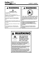
•
DO NOT OPERATE THE ENGINE AT AN ANGLE
GREATER THAN 25° OR SEVERE ENGINE DAMAGE
WILL OCCUR. PROPER ENGINE OIL LEVEL MUST BE
MAINTAINED TO ACHIEVE MAXIMUM ANGLE OF
OPERATION OF 25°. (See Engine Owner’s Manual for proper
oil level.)
•
Never allow spectators to stand and watch machine in operation
without proper hearing and eye protection and standing at a safe
distance. Loud noise and flying debris may cause severe injury.
Do not operate around water, gas, power or phone lines. Check
with property owner or call utilities if not sure.
Avoid fences and clear away other objects (i.e. sticks, stones,
metal, etc.).
Be aware of the possibility of foreign objects imbedded in or
buried around the stump. Do not cut crosswise of roots above
ground to prevent roots being thrown.
If unusual vibration occurs, stop engine immediately and correct
problem before continuing operation.
Keep all guards in place and properly secured during operation.
Keep all safety devices working properly and all other machine
parts in good working condition.
Never leave the controls unattended while in operation. Be sure
machine is not capable of operation when left unattended.
•
•
•
•
•
•
•
•
•
•
•
•
•
•
•
•
•
•
Stop engine and remove key when repairing or adjusting machine
or drive belts.
Keep engine in good condition, service as instructed in engine
manual.
Do not touch engine while running or hot (serious burns may
result).
Allow all machine parts to cool completely before servicing or
making adjustments. Hot machine parts can cause severe burns.
Do not run the machine without a complete number of teeth in the
cutter wheel tightened to the correct torque.
Do not place machine in free wheel without first placing tongue
stake in the ground.
Park machine on level surfaces only. Lower cutter head to the
ground and use wheel chocks to prevent unattended movement.
Do not operate stump cutter in dark, dim lit, or concealed areas.
Keep machine clean and clear of debris to eliminate fire hazard.
It is especially important to clean any oil or fuel spills to prevent
the danger of fire.
Keep cutter wheel skirt guards in good condition to help control
chips during grinding.
Keep safety and instructional decals clean and replace any that
are damaged, difficult to read, or missing. Decals may be
purchased from J.P. Carlton or an authorized dealer.
8
7500
•
•
•
•
•
•
•
•
•
•
•
Make sure safety pins and safety chock
are in position before towing. Always
crisscross safety chains when towing.
Check engine oil at dipstick. Add to full
mark, if required. Engine must be level
(see Machine Maintenance section).
Check hydraulic oil level. A sight glass
is located on the hydraulic tank. Add oil
if required.
Inspect dry air filters. REPLACE, if
necessary, WITH FACTORY AIR
FILTER ONLY. Do not blow out or tap
on ground. Replace inner safety filter
when dirty or when the outer air filter
has been changed 3 times. Do not blow
out the inner safety filter or tap on
ground. (See Engine Assembly section
for part numbers.)
Check condition of tires. Inflate to
proper pressure.
Check wheel lug nuts.
Inspect towing hitch, safety chains and
towing lights.
Check condition and tightness of engine
belts. (See Servicing Belts section)
New belts will stretch and become loose
as machine runs. Check belt tension
often when belts are new.
Check for any loose, broken, cracked, or
missing cutter teeth and pockets.
Tighten or replace any loose or damaged
teeth or pockets before running stump
cutter.
Inspect bolts, hydraulic fittings, wiring
harnesses, and hoses for looseness, wear,
or leakage. Replace if necessary.
Machines are equipped with purgable
bearings on the cutter wheel shaft and
the jackshaft. Purge with new grease
EVERYDAY.
DAILY CHECKLIST
PINS
PURGE BEARINGS WITH GREASE DAILY
9
7500
MACHINE CONTROLS
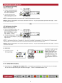
ENGINE CONTROLS - Refer to engine manufacturers owners’ manual for controls, operation,
and service.
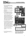
•
Start the engine using the key switch
located on the lower left hand side of the
swing-out control panel. Press and hold
the Murphy By-Pass while turning the
key switch. Run the engine a few
minutes to allow the oil to circulate
before starting to operate the functions.
OIL PRESSURE, OIL
TEMPERATURE, AND
ALTERNATOR GAUGES
ALSO PROVIDED
MURPHY BY-PASS
KEY SWITCH
DO NOT OPERATE THE ENGINE
AT AN ANGLE GREATER THAN
25° OR SEVERE ENGINE DAMAGE
WILL OCCUR. PROPER ENGINE
OIL LEVEL MUST BE MAINTAINED
TO ACHIEVE MAXIMUM ANGLE
OF OPERATION OF 25°. (See Engine
Owner’s Manual for proper oil level.)
HYDRAULIC CONTROLS
•
A series of hydraulic controls are located
on the machine and are clearly marked.
•
Lever 1 – Cutter Wheel (Lift)
(Shown as CUTTER HEAD –RIGHT/LEFT on
radio transmitter.)
•
•
This lever operates the cutter head lift
function, which raises and lowers the
cutter head.
Lever 2 – Tongue
This lever operates the tongue extension
function, which moves the machine
toward the stump and pulls the machine
back away from the stump.
Lever 3 – Boom Travel (Swing)
LEVER 1
LEVER 2
LEVER 3
(Shown as CUTTER HEAD –RIGHT/LEFT on
radio transmitter.)
This lever operates the cutter head swing
function, which swings the boom back
and forth in a left-right-left-right-left…
motion.
10
7500
MACHINE CONTROLS
SWING SPEED ADJUSTMENT
•
Adjust swing speed for smooth
operation. Turn valve counter-clockwise
to slow cutter head swing as engine
speed increases. Close valve by turning
clockwise to allow head to move side to
side at low engine RPM.
CUTTER WHEEL ENGAGEMENT
•
•
With the engine RPM at idle, engage the
cutter wheel by lifting the engine slide
lock and slowly pulling the engagement
lever toward the front of the machine. It
may be easier to lift the engine slide lock
if you first press down on the
engagement lever.
To disengage the cutter wheel, reduce
the engine RPM to idle and slowly push
the engagement lever back toward the
cutter wheel. The engine slide lock
should automatically go into place, make
sure it is locked in place.
CUTTER WHEEL ENGAGED
ENGINE SLIDE LOCKED
CUTTER WHEEL DISENGAGED
OPTIONAL HYDRAULIC CONTROLS
THROTTLE
•
If equipped, the throttle switch increases
or decreases engine RPM.
ENGAGER
•
If equipped, the engager switch engages
or disengages the cutter wheel.
THROTTLE & ENGAGER SWITCHES
11
7500
OPTIONAL REMOTE CONTROL
OPERATION – WIRED
• The control functions operate the same
on a remote control machine as they do
on a swing-out machine. Instead of
having the machine mounted control
levers as described earlier in this section,
there are toggle switches on the machine
control box and on the remote control
unit. The toggle switches on the
machine control panel can be used to
operate the machine for short-term
operation to test the operation of the
functions.
•
•
•
Use the switches on the remote
transmitter to operate the machine at the
job site. For a remote control machine
with a wired remote transmitter, turn the
Machine ON/Remote ON switch to
Remote On and turn the Engine switch
on the transmitter to RUN. Start the
engine using the key switch located on
the upper right hand side of the machine
control panel. Press and hold the
Murphy By-Pass while turning the key
switch. Run the engine a few minutes to
allow the oil to circulate before starting
to operate the functions. After the
engine has been running for a few
minutes, test the remote transmitter by
testing the functions for correct
operation. After testing the functions
and everything is operating correctly,
begin grinding the stump as described in
the Machine Operation section of this
manual.
On a remote machine, the Swing Speed
Adjustment control is installed on the
side of the machine control box.
Adjust swing speed for smooth
operation. Turn valve counter-clockwise
to slow cutter head swing as engine
speed increases. Close valve by turning
clockwise to allow head to move side to
side at low engine RPM.
MACHINE CONTROLS
REMOTE CONTROL MACHINE – TOGGLE SWITCHES
REMOTE PLUG
RECEIVER
PUSH TO
REMOTE ON
MURPHY
BY-PASS
KEY
SWITCH
WIRED REMOTE TRANSMITTER WITH 25’ CORD
SWING SPEED
ADJUSTMENT
12
7500
MACHINE CONTROLS
SAFETY
• NEVER SERVICE A MACHINE WITH THE ENGINE RUNNING, SEVERE
PERSONAL INJURY COULD OCCUR. TURN ENGINE OFF THEN REMOVE
IGNITION KEY AND DISCONNECT POSITIVE BATTERY CABLE TO AVOID
STARTING MACHINE ACCIDENTALLY.
• CUTTER WHEEL MUST BE DISENGAGED BEFORE TURNING ENGINE
ON/OFF AND BEFORE SERVICING A MACHINE. OTHERWISE SEVERE
PERSONAL INJURY COULD OCCUR AS WELL AS MACHINE DAMAGE.
• ALL MACHINE PARTS MUST COME TO A COMPLETE STOP AND HAVE
TIME TO COOL COMPLETELY BEFORE SERVICING A MACHINE OR
SEVERE INJURY COULD OCCUR, POSSIBLY SERIOUS BURNS AND/OR
DISMEMBERMENT.
• PLACE THE CUTTER WHEEL ON THE GROUND WHEN PERFORMING
SERVICE ON A MACHINE.
OPTIONAL RADIO CONTROL
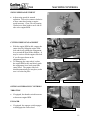
CONVERTING FROM WIRED TO
RADIO TRANSMITTER
• To change from a wired to a radio
(wireless) transmitter, remove the cover
on the control box. There are 3 bolts on
each side.
• Turn cover over and drill holes in the
control box wall for attaching the radio
control receiver; make sure the hole
locations match the bolt locations on the
radio receiver. Attach the radio receiver
to the control box and replace the cover.
• Use the wiring and connector diagrams,
in the radio control manual included at
the back of this manual, to wire directly
to the appropriate contacts of the
machine electronics. Contact your
Carlton dealer if you need assistance not
the radio control manufacturer.
• The radio transmitter and receiver will
be programmed at the factory when
purchased as a set.
REMOVE THE CONTROL BOX
COVER BOLTS (BOTH SIDES)
AND REMOVE COVER
DRILL HOLES IN THIS SIDE OF THE
COVER TO MOUNT THE RECEIVER
DRILL HOLES IN THE RIGHT SIDE OF THE COVER
(SHOWN ABOVE) AND MOUNT THE RADIO CONTROL
RECEIVER INSIDE.
THE RADIO CONTROL
RECEIVER, SHOWN AT
THE RIGHT, MUST BE
INSTALLED IN THE
CONTROL BOX
13
7500
MACHINE CONTROLS
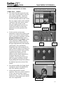
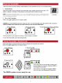
OPERATION – WIRELESS
•
•
•
•
•
•
•
•
THE CUTTER WHEEL MUST BE
DISENGAGED BEFORE STARTING
THE MACHINE.
To start the engine and radio control
transmitter, follow these instructions.
On the machine, turn the ignition key
switch to ON and the engine switch to
Remote On.
On the transmitter, press the E-STOP
button down.
Toggle any switch on the transmitter.
Twist the E-STOP button clockwise to
release. Release the E-STOP button
within 10 seconds to power up or the
unit will power down. When the
transmitter is operating there is a yellow
light that will be flashing, the light is
indicated in the picture at the right.
(Read the radio control manual for more
information on the meaning of different
lights and colors.) If the transmitter
doesn’t start, check the transmitter for
stuck switches, it will not start with a
switch in the ON position.
Now start the engine, turn the key switch
while pressing the by-pass switch to start
the machine. If the engine doesn’t start
right away and you have to restart it,
turn the key switch OFF and back ON.
Make sure the light on the transmitter is
still on, and restart the engine by turning
the key and pressing the by-pass switch.
If you lose the connection (light off),
repeat the procedure from the beginning
and perform each step exactly as
described. Test controls for proper
operation.
The E-STOP button turns off the
transmitter and the machine when it is
pressed down.
BY-PASS
SWITCH
KEY
SWITCH
PUSH SWITCH UP
TO REMOTE ON
LOW BATTERY /
FAULT LIGHT
TOGGLE ANY
SWITCH
E-STOP BUTTON
A YELLOW LIGHT
WILL BE FLASHING
WHEN TRANSMITTER
IS SENDING SIGNALS
TO THE RECEIVER
THE RADIO TRANSMITTER SHOWN HERE IS FOR A
3-FUNCTION MACHINE. IF YOUR MACHINE IS
EQUIPPED WITH A THROTTLE AND ENGAGER, YOU
WILL RECEIVE A TRANSMITTER WITH 5 FUNCTIONS.
THE LOW BATTERY AND RADIO ON LIGHTS MAY BE
IN A DIFFERENT LOCATION ON A 5-FUNCTION UNIT.
NEVER WELD ON A MACHINE WITH
RADIO CONTROLS WITHOUT FIRST
DISCONNECTING THE RECEIVER WIRE
HARNESS, OTHERWISE THE RADIO
RECEIVER WILL BE DESTROYED.
14
7500
MACHINE CONTROLS
PROGRAMMING – WIRELESS
•
•
•
If there is a problem with the receiver or
the transmitter and either has to be
replaced, you will need to program the
new unit to communicate with the
existing unit. Or if you have more than
one transmitter for this machine, it will
need to be programmed to communicate
with the existing receiver.
To program the transmitter and receiver,
you have to download the transmitter’s
unique code into the receiver. There are
complete instructions along with colored
illustrations in the radio control manual
included in the back of this manual.
To access the receiver, remove the cover
from the machine control box.
•
Remove the radio receiver panel by
unlatching the plastic tabs on either side
of the receiver; see the radio control
manual included in this manual at the
back. The receiver panel will now slide
out of the cap.
•
Follow the instructions in the radio
control manual to download the ID
Code. There are specific instructions
that need to be followed and
corresponding illustrations. The radio
control manual is included in the back of
this manual.
Push the receiver panel back up into the
cap until the tabs snap back into place.
•
•
REMOVE
COVER
RELEASE THE RADIO
RECEIVER CAP BY
UNLATCHING THE
TABS ON EACH SIDE
Always replace the machine cover when
maintenance or troubleshooting is
complete. DO NOT RUN MACHINE
WITHOUT ALL GUARDS & COVERS
IN PLACE AND SECURED.
15
7500
MACHINE CONTROLS
TROUBLESHOOTING
LOW BATTERY LIGHT
SEE THE RADIO CONTROL MANUAL
FOR ANY OPERATING PROBLEMS
WITH THE RADIO RECEIVER &
TRANSMITTER
(Included in the back of this manual)
•
•
•
First check the batteries to make sure
they are providing enough power to
operate the transmitter.
There is a low battery light on the
transmitter, when it starts flashing you
have approximately 10 hours of
operation left.
Remove the back cover on the
transmitter. Remove old batteries and
replace with new batteries. The
transmitter operates using 4 AA alkaline
batteries.
•
Next, open the cover on the machine
control box. You will need to be able to
see the lights on the receiver to compare
to the trouble indicators on the receiver
diagnostic list in the radio control
manual. Check the light configuration
and compare it to the Receiver
Diagnostic list in the radio control
manual.
•
If status light on radio receiver is
flashing red, a fuse is blown. To change
a fuse, remove the receiver panel from
the cap and change the fuse. Inspect
wiring for short circuits (e.g. bare wires).
If problem re-occurs, call for service.
Push the receiver panel back into the cap
until the tabs snap back into place.
•
REMOVE THE BACK COVER TO ACCESS THE
BATTERIES – THERE ARE 4 SCREWS HOLDING IT IN
PLACE. THE BATTERY COMPARTMENT IS LABELED
FOR CORRECT BATTERY ORIENTATION.
REMOVE
OR RAISE
COVER
COMPARE THE LIGHT CONFIGURATION ON THE
RECEIVER TO THE DIAGNOSTIC CHART IN THE RADIO
CONTROL MANUAL
Always replace the machine cover when
maintenance or troubleshooting is
complete. DO NOT RUN MACHINE
WITHOUT ALL GUARDS & COVERS
IN PLACE AND SECURED.
REPLACE FUSE
16
7500
TOWING GUIDE
SAFETY: NEVER ALLOW INEXPERIENCED DRIVERS TO TOW
MACHINERY. Always make sure ball size is same size as coupler on equipment.
•
•
•
•
•
•
•
•
•
•
•
•
•
•
Always make sure safety pins and chock block
are in place before towing.
Always make sure towing ball and hitch coupler
are the same size and that they are not worn.
Check hitch for secure installation and make
sure safety chains are properly installed.
Crisscross safety chains under hitch to provide
support in the event of failure. Chains may be
twisted to shorten to compensate for excessive
length. Should the tongue contact the ground at
highway speeds, the machine tongue may dig in
and catapult the machine into traffic. USE
YOUR SAFETY CHAINS.
When connecting machine to tow vehicle, take
care to ensure that the tongue of the stump
grinder rides level or slightly down in the front.
A proper amount of tongue weight is required to
allow machine to tow properly. Too little
tongue weight will result in wandering or
fishtailing.
Check towing lights for proper operation.
Never hitch or unhitch machine on anything but
level ground. Use chocks on wheels to prevent
inadvertent movement (no parking brakes).
Lock jack in traveling position before towing.
Use a tow vehicle that is rated to tow a machine
of this weight. Make sure the hitch is heavy
enough and built strong enough.
Towing will affect handling, allow for extra
stopping distances.
Start and stop gradually.
Tow at a safe, reasonable speed. Obey posted
speed limits.
Slow down over rough terrain.
Never tow with stump cutter motor running.
Never back up to a stump with cutter wheel
engaged.
SAFETY PINS
SAFETY CHAINS
TOW WITH MACHINE RIDING LEVEL
17
7500
MACHINE OPERATION
STARTING - READ ENGINE MANUFACTURERS OWNERS’ MANUAL BEFORE
STARTING.
•
•
•
•
•
•
Check all fluids before starting.
Drive belts must be disengaged before starting.
Inspect all connections, teeth, tires, etc. (See Daily Checklist).
Start engine at half speed and allow sufficient time for oil to circulate before proceeding.
Test controls for proper operation.
Avoid transversing slopes.
•
DO NOT OPERATE THE ENGINE AT AN ANGLE GREATER THAN 25° OR
SEVERE ENGINE DAMAGE WILL OCCUR. PROPER ENGINE OIL LEVEL MUST
BE MAINTAINED TO ACHIEVE MAXIMUM ANGLE OF OPERATION OF 25°. (See
Engine Owner’s Manual for proper oil level.)
DO NOT OPERATE AROUND WATER, GAS, POWER OR PHONE LINES. IF IN
DOUBT, CHECK BEFORE GRINDING.
WEAR FACE SHIELD AND HEARING PROTECTION.
KEEP CLEAR OF CUTTING WHEEL AND MOVING MACHINE PARTS.
KEEP SPECTATORS AWAY.
•
•
•
•
•
Position the machine at stump with cutter wheel
a slight distance away from stump. Do not
engage cutter wheel when backing up to
stump. Hitting the stump with cutter wheel
running will break the Poly Chain® belt.
•
Remove tongue safety pin before beginning to
cut stump.
18
7500
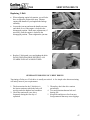
•
MACHINE OPERATION
Lift boom and remove boom chock block.
LIFT ENGINE SLIDE
LOCK HANDLE
•
•
•
•
•
Reduce engine RPM to idle.
Raise cutter head clear of stump.
Engage cutter head drive belts by pushing down
on engagement handle to relieve pressure on
engine slide stop. Lift slide stop and slowly pull
handle back to engage belts.
Increase engine RPM to full.
Test controls for proper operation, speed, and
unobstructed movement.
PULL THE ENGAGEMENT HANDLE
BACK SLOWLY TO ENGAGE
CUTTER WHEEL
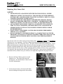
•
•
•
Cutter head swing speed should be adjusted to a
rate that will allow cutter wheel to pass through
stump smoothly. If jerking, bouncing or
significant drops in engine speed occur, swing
rate is too rapid and must be decreased.
Swing speed should be determined and adjusted
with the controls in the full open position.
A counter-rotating valve is located within the
hydraulic system to adjust this speed. Turning
the handle counter-clockwise will open the
bypass and slow swing action. Turning it
clockwise will increase swing rate.
SWING SPEED
ADJUSTMENT FOR
MANUALLY
OPERATED MACHINE
SWING SPEED ADJUSTMENT FOR
REMOTE MACHINE
19
7500
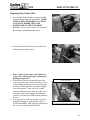
•
•
•
•
•
•
•
•
•
•
•
•
•
MACHINE OPERATION
Lower spinning cutter wheel to stump and make
a few light passes at stump to get a feel for the
cutting action.
Gradually increase cutting action and work
away at stump by swinging cutter wheel left-toright-to-left through stump in a sideways
motion. Smooth, effortless cutting lengthens
machine life, minimizes downtime and is more
profitable in the long run.
Continue cutting stump by adjusting cutting
wheel progressively lower until stump is cut
well below ground level.
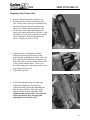
Swing cutter wheel clear of stump and extend
tongue to position machine closer to stump for
next series of passes and continue cutting.
Continue in this manner until stump has been
removed.
Larger stumps may require repositioning
machine to work at best advantages.
Raise cutter wheel clear of stump and return to
center position.
Withdraw tongue extension.
Reduce engine speed to idle and disengage drive
belts. DO NOT DISENGAGE DRIVE
BELTS AT A HIGH ENGINE SPEED.
Damage to belts and machine will occur.
DO NOT TURN OFF MOTOR. Engine must
be allowed to cool slowly at idle for 3-5 minutes
to avoid damage.
At low engine RPM cutter wheel swing speed
control needs to be closed for cutter head to
swing. Turn clockwise to close.
Turn off motor.
Allow cutter wheel to come to a full stop before
inspecting work area.
20
7500
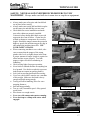
MACHINE OPERATION
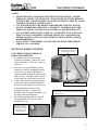
For optimal performance, the stump should be cut with the portion of the cutter wheel
shown. NEVER UNDERCUT THE STUMP. Undercutting the stump can cause severe
kickback, vibration and component damage. NEVER CUT THE STUMP FROM THE TOP.
The cutter wheel will throw debris up and toward the operator, instead of down and under the
machine.
21
7500
MACHINE MAINTENANCE
SAFETY
•
•
•
•
•
NEVER SERVICE A MACHINE WITH THE ENGINE RUNNING, SEVERE
PERSONAL INJURY COULD OCCUR. TURN ENGINE OFF THEN REMOVE
IGNITION KEY AND DISCONNECT POSITIVE BATTERY CABLE TO AVOID
STARTING MACHINE ACCIDENTALLY.
CUTTER WHEEL MUST BE DISENGAGED BEFORE TURNING ENGINE
ON/OFF AND BEFORE SERVICING A MACHINE. OTHERWISE SEVERE
PERSONAL INJURY COULD OCCUR AS WELL AS MACHINE DAMAGE.
ALL MACHINE PARTS MUST COME TO A COMPLETE STOP AND HAVE
TIME TO COOL COMPLETELY BEFORE SERVICING A MACHINE OR
SEVERE INJURY COULD OCCUR, POSSIBLY SERIOUS BURNS AND/OR
DISMEMBERMENT.
PLACE THE CUTTER WHEEL ON THE GROUND WHEN PERFORMING
SERVICE ON A MACHINE.
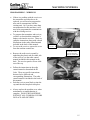
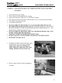
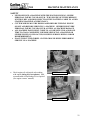
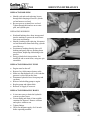
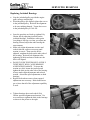
Check engine oil at dipstick; take reading
with engine sitting level (see photos). Add
recommended oil and change oil as required.
(See engine owners’ manual)
INCORRECT POSITION
CORRECT POSITION
22
7500
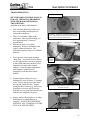
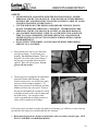
•
•
•
•
•
MACHINE MAINTENANCE
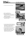
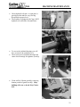
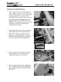
Check hydraulic oil tank. A sight glass is
provided on the tank for easy viewing.
Keep filled to proper level.
The machine is equipped with Citgo AW32
hydraulic oil at the time of manufacture.
To access the jackshaft bearings you will
have to remove the jackshaft cover.
Check setscrews in jackshaft bearings and
cutter wheel bearings for tightness (weekly).
Clean out Poly Chain® guard by removing
bottom portion of guard (weekly). Chip
buildup will wear or break Poly Chain®
belt.
23
7500
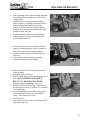
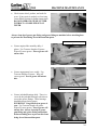
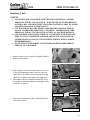
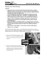
•
MACHINE MAINTENANCE
Check cutter wheel, pockets, and teeth for
wear. If any repair is needed, see Servicing
Cutter Wheel section for further instructions.
DO NOT OPERATE STUMP CUTTER
WITHOUT A COMPLETE SET OF
TEETH.
Always clean tip of grease gun fitting and grease fitting on machine before attaching hose
to prevent dirt from being forced into machine parts.
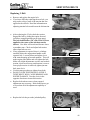
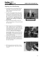
ENGINE SLIDE GREASE FITTING
•
Grease engine slide assembly daily, 6
places. Use Texaco® Starplex II grease.
Wipe off excess grease. Excess grease will
attract dirt.
•
Grease engagement lever weekly. Use
Texaco® Starplex II grease. Wipe off
excess grease. Excess grease will attract
dirt.
ENGAGEMENT LEVER GREASE FITTING
•
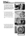
Grease jackshaft bearings daily. There is a
cover on the jackshaft bearings with slots to
access the grease fittings. These bearings
should be purged using grease
EVERYDAY. Purge until clean grease is
seen. Use Texaco® Starplex II grease.
Wipe off excess grease. Excess grease will
attract dirt. Always clean tip of grease
gun fitting and grease fitting on machine
before attaching hose to prevent dirt from
being forced into machine parts.
JACKSHAFT BEARING GREASE FITTING
24
7500
•
Grease cutter wheel shaft bearings daily.
These bearings should be purged using
grease EVERYDAY. Purge until clean
grease is seen. Use Texaco® Starplex II
grease. Wipe off excess grease. Excess
grease will attract dirt. Always clean tip
of grease gun fitting and grease fitting on
machine before attaching hose to prevent
dirt from being forced into machine
parts.
•
Grease the bearing supported stub shaft
every 1000 hours of operation using
Texaco® Starplex II grease. The grease
fitting is easily accessible behind the V-belt
guard. Apply grease using a hand held
grease gun until the pin extends from the
pressure relief valve (located 180°from
grease fitting on the bearing). Wipe off
excess grease. Excess grease will attract
dirt.
•
A grease fitting is on the end of the stub
shaft to grease the spline coupling. Apply 2
to 3 shots of grease approximately every
1000 hours of operation. Wipe off excess
grease. Excess grease will attract dirt.
DO NOT over grease, over greasing could
cause a hydraulic type lift on seals.
MACHINE MAINTENANCE
PIN
GREASE APPROXIMATELY EVERY
1000 HOURS OF OPERATION
25
7500
•
Grease bottom pivot hardened bushings
weekly. Use Texaco® Starplex II grease.
Wipe off excess grease. Excess grease will
attract dirt. The bottom pivot grease
fittings (3) are located on the tongue below
the battery box.
•
Grease spindles every 2 to 3 months.
Spindles are easy lube type. Remove rubber
grommet and grease at grease fitting until
grease is seen around grease fitting.
•
Grease tongue extension every 6 months
with a light coating of Texaco® Starplex II
grease.
MACHINE MAINTENANCE
26
7500
•
The model 7500, as well as all of our
machines, is built to be rugged performers.
Your new machine is sturdy and our design
goals are simplicity and reliability.
LUBRICATION CHART
•
A regularly scheduled maintenance
program will pay big dividends in machine
life, performance and avoided downtime.
Lubrication Schedule
•
USE TEXACO® STARPLEX II GREASE.
27
7500
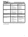
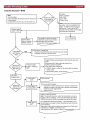
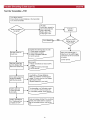
TROUBLESHOOTING GUIDE
COMPLAINT
CAUSE
CORRECTION
Engine will not start. (See Engine
Manufacturers’ Manual for further
information.)
Hydraulic system loss of power.
•
•
•
•
•
•
Loose ground wire.
Loose hot wire.
Dead battery.
Low oil.
Valve set too low.
Splined pump
coupling worn.
Bad cylinder.
Bad Pump.
Cutter head speed
adjustment screw
turned wide open.
•
•
•
•
•
•
Clean and tighten.
Clean and tighten.
Recharge or replace.
Refill with correct oil.
Adjust relief valve.
Remove pump coupler.
•
•
•
Belt tension too
loose.
Belt out of alignment.
Engaging or
disengaging belt at
high engine RPM.
Belt keeper too far
from belt.
Belt worn.
Pulley worn.
•
Replace cylinder packing.
Replace Pump.
Screw in speed
adjustment screw to close
bypass. Re-adjust for “no
bounce” cutting.
Tighten.
Swing cylinder loss of power.
•
•
•
Belt Squeal.
•
Belt jumping off.
•
•
•
•
•
Cutter wheel vibration.
Cutter wheel throwing teeth.
Cutter wheel breaking teeth.
•
•
Align Pulleys.
Only engage or disengage
belts at low engine
speeds.
•
Adjust keeper closer to
belt.
Replace belt.
Replace pulley.
Replace missing teeth.
Always replace pockets in
pairs across from each
other.
Install correctly with like
pairs of teeth directly
across from each other.
Replace pocket.
Clean pocket and replace
missing teeth.
Replace cutter wheel.
•
•
•
•
•
•
Tooth missing.
Pocket out of
balance.
•
Improper tooth
arrangement.
•
•
•
Bad pocket.
Dirt in pocket.
•
•
•
Cutter wheel worn
where tooth sits.
Teeth set too far out
of pocket.
•
•
•
Use gauge to set teeth
correctly.
28
7500
TROUBLESHOOTING GUIDE
COMPLAINT
CAUSE
CORRECTION
Cutter wheel stops turning.
•
•
•
•
•
•
•
Belt not engaged.
Belt loose.
Engine belt broke.
Poly Chain® belt broken.
Sheared key in shaft.
Broke cutter wheel shaft.
Belt guards rubbing on
jack shaft or cutter wheel
shaft.
Jackshaft or cutter wheel
bearings going bad.
Stub shaft bearing bad.
Grease fitting clogged.
Counter-balance valve is
out of adjustment.
•
•
•
•
•
•
•
Adjust yoke assembly.
Tighten belt.
Replace belt.
Replace belt.
Replace key.
Replace shaft.
Re-position guards off of
shafts.
•
Replace bearings.
•
•
•
Cylinder bad.
3-position switch on
machine control panel is in
off position.
6 pin connector pins are
touching and grounding
machine out.
Y-Connection in remote
cable pulled apart.
•
•
Replace bearing.
Replace fitting
Adjust counter-balance
valve to equalize swing
speed.
Replace cylinder.
Position switch on
machine to remote and
remote kill switch to on.
Spread pins apart on inside
of connector.
Roar in machine when cutter
wheel is engaged.
•
Bearing will not take grease.
Cutter head swings faster one
way than the other.
Machine will not run with
remote hooked up.
•
•
•
•
•
•
•
•
•
Reconnect wires in splice
in remote cable.
For all Radio Transmitter or Receiver problems, see the Radio Control Manual included at
the back of this manual.
29
3
5
7
4
6
8
R
BATTERY
STARTER
PRE-HEATER
ENGINE
CONNECTOR
10 9
1
2
BIG R
BIG R
BIG BK
(GROUND TO ENGINE)
BIG BL
58
30
40 AMP
FUSE
19
KEY
SWITCH
50
15/54
17
O
Y
BK
BIG BL/BK
BR
BK
BL
BY-PASS
GR
BL
Y/BK
86
87
87A
ENGINE
85
30
RELAY
BR/BK
BIG BK
STARTING SERIAL # 302 ('06)
BL
HOUR METER
ALT.
LIGHT
OIL TEMP
LIGHT
DIODE
85
86
30
OIL PRESS.
LIGHT
ACTUAL RELAY
CONNECTIONS
BL
DIODE
87
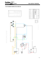
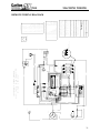
7500 MACHINE STANDARD WIRING DIAGRAM
W/KEY SWITCH, BY-PASS, & PRE-HEAT
87A
RED
YELLOW
ORANGE
PURPLE
GRAY
GREEN
BLUE
BLACK
BROWN
WHITE
RED/BLACK
ORANGE BLACK
YELLOW/BLACK
YELLOW/RED
ORANGE/RED
BLUE/BLACK
BLUE/RED
BROWN/BLACK
GREEN/BLACK
BLACK/YELLOW
BLACK/BLUE
BLACK/RED
BLACK/GREEN
BLACK/BROWN
7500-17D
CHECKED BY:
CURRENT
(AHF/1/11/10)
J.P. CARLTON CO. DIVISION DAF INC
PROFESSIONAL
TREE
EQUIPMENT
Carlton
EC # 030515-A - WAS 7500-5G
EC # 041020-B - ADDED PRE-HEATER
RELAY AND WIRING; HOUR METER POS.
WIRE WAS TO ENG. RELAY & NEG. WAS
SHOWN GROUND TO ENGINE.
EC # 070713-C - REMOVED PRE-HEATER
RELAY & REWIRED PRE-HEATER. REV'D
WIRES FROM ENGINE PLUG.
EC # 011110 - REVISED ENGINE
CONNECTOR.
=
=
=
=
=
=
=
=
=
=
=
=
=
=
=
=
=
=
=
=
=
=
=
=
COLOR CODES
R
Y
O
PR
GY
GR
BL
BK
BR
W
R/BK
O/BK
Y/BK
Y/R
O/R
BL/BK
BL/R
BR/BK
GR/BK
BK/Y
BK/BL
BK/R
BK/GR
BK/BR
7500
MACHINE WIRING
STANDARD WIRING DIAGRAM
30
30
58
BATTERY
STARTER
BIG BL
19
50
15/54
17
KEY
SWITCH
BIG R
BL
BIG BL/BK
Y/BK
BL/BK
R/BK
O
TERMINAL BOX
1
2
O
5
4
BL/BK
O
O
6
Y/BK
10
9
11
3
DIODE
5
13
4
12
14
6
DIODE
BL
BL
Y
R
Y/B
R
15
7
Y
BK
16
8
R
BIG R
BL
Y
BIG BL/BK
R
BIG BK
BIG BK
DIODE
BIG BK
Y/BK
85
30
BR/BK
ENGINE
O/BK
DIODE
EXT.
2
DIODE
O/BK
O/BK
DIODE
LIFT
3
DIODE
ELECTRO-HYDRAULIC
CONTROLS
O/BK
SWING
1
DIODE
BL
BR
86
87
87A
(GROUND TO BOLT ON DECK)
HOUR METER
RED FROM BREAKAWAY SWITCH
FOR ELECTRIC BRAKES
BL/BK
R/BK
R/BK
16 PIN CONNECTOR
2
1
O
LIFT
OIL PRESS.
LIGHT
EXT.
FUSE BOX
3
BK
ON/OFF
SWITCH
BL/BK
SWING
OIL TEMP
LIGHT
6AMP
20AMP
ALT.
LIGHT
BL
O/BK
PRE-HEATER
40AMP
O/BK
RELAY
O
O/BK
Y
BK
3
5
7
4
6
8
DIODE
ENLARGED VIEW
0/BK
10 9
1
2
ENGINE
CONNECTOR
BY-PASS SWITCH
GR
85
87
30
BL
SILVER SIDE OF
DIODE POINTS AWAY
FROM THE O/BK WIRE
1
2
3
4
5
6
7
8
9
10
11
12
13
PIN #
=
=
=
=
=
=
=
=
=
=
=
=
=
=
=
=
=
=
=
=
=
=
=
=
RED
YELLOW
ORANGE
PURPLE
GRAY
GREEN
BLUE
BLACK
BROWN
WHITE
RED/BLACK
ORANGE BLACK
YELLOW/BLACK
YELLOW/RED
ORANGE/RED
BLUE/BLACK
BLUE/RED
BROWN/BLACK
GREEN/BLACK
BLACK/YELLOW
BLACK/BLUE
BLACK/RED
BLACK/GREEN
BLACK/BROWN
COLOR CODES
R
Y
O
PR
GY
GR
BL
BK
BR
W
R/BK
O/BK
Y/BK
Y/R
O/R
BL/BK
BL/R
BR/BK
GR/BK
BK/Y
BK/BL
BK/R
BK/GR
BK/BR
ORANGE
BLACK
ORANGE
RED
RED/BLACK
YELLOW
YELLOW/BLACK
BLUE
BLUE/BLACK
ORANGE/RED
YELLOW/RED
BLACK/RED
BLUE/RED
COLOR
R7500-1
CHECKED BY:
PROFESSIONAL
TREE
EQUIPMENT
CURRENT
(AHF/1/10/10)
J.P. CARLTON CO. DIVISION DAF INC
Carlton
EC # 030515-H - CHG'D WIRE FROM KEY
SWITCH TO KILL SWITCH
ADDED GROUND WIRE TO 16 PIN CONNECTOR
& FROM BATTERY GROUND TO CENTRAL GROUND
EC # 030604-K - ADDED DIODES TO
CONTROLS & ADDED NOTE
EC # 041012-M - ADDED PRE-HEATER RELAY
& WIRING (WAS WIRED DIRECTLY TO KEY
SWITCH). FUSE NEXT TO 40AMP CHANGED
TO 50AMP. CHG'D JUMP WIRES TO BUS BAR.
EC # 051128-P - REWIRED
ELECTRO-HYDRAULIC CONTROLS, REARRANGED
WIRES, & TURNED DIODES AROUND; REMOVED
PRE-HEAT RELAY; REVISED JUNCTION BOX;
TURNED ON/OFF (KILL) SWITCH AROUND.
EC # 011010 - RENAMED SCHEMATIC FROM
7500-5P TO R7500-1. REVISED ENGINE
CONNECTOR-SWITCHED 6AMP CIRCUIT
BREAKER WITH 20 AMP CIRCUIT BREAKER.
LINKED 6AMP CIRCUIT BREAKER WITH 40AMP
CIRCUTI BREAKER WITH BUSSBAR.
GROUND
POWER
GROUND
SWING (R)
SWING (L)
LIFT (UP)
LIFT (DOWN)
EXTENSION (IN)
EXTENSION (OUT)
THROTTLE (UP)
THROTTLE (DOWN)
CLUTCH (ENGAGE)
CLUTCH (DIS-ENGAGE)
FUNCTION
16 PIN CONNECTOR DESCRIPTION
ACTUAL RELAY
CONNECTIONS
86
87A
7500 REMOTE WIRING DIAGRAM
W/KEY SWITCH, 16-PIN CONNECTOR,
BY-PASS, & PRE-HEAT
Y
7500
MACHINE WIRING
REMOTE WIRING DIAGRAM
31
3
2
1
SWING
O/BK
EXT.
3
2
1
BL
O/BK
3
2
1
BL/BK
Y
R
ENGINE
LIFT
R/BK
Y/BK
O/BK
O
BK
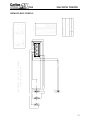
7500 REMOTE BOX WIRING DIAGRAM
W/16-PIN CONNECTOR
9
1
11
3
5
12 13
4
14
6
15
7
16
8
=
=
=
=
=
=
=
=
=
=
=
=
=
=
=
=
=
=
=
=
=
RED
YELLOW
ORANGE
PURPLE
GRAY
GREEN
BLUE
BLACK
BROWN
WHITE
RED/BLACK
ORANGE BLACK
YELLOW/BLACK
YELLOW/RED
ORANGE/RED
BLUE/BLACK
BLUE/RED
BROWN/BLACK
BLACK/YELLOW
BLACK/BLUE
BLACK/RED
1
2
3
4
5
6
7
8
9
PIN #
C7500-1
CHECKED BY:
CURRENT
(AHF/1/10/10)
J.P. CARLTON CO. DIVISION DAF INC
EC # 011010-RENAMED FILE FROM
7500-18D TO C7500-1.
R
Y
O
PR
GY
GR
BL
BK
BR
W
R/BK
O/BK
Y/BK
Y/R
O/R
BL/BK
BL/R
BR/BK
BK/Y
BK/BL
BK/R
COLOR CODES
ORANGE
BLACK
ORANGE/BLACK
RED
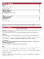
RED/BLACK
YELLOW
YELLOW/BLACK
BLUE
BLUE/BLACK
POWER IN
POWER OUT
GROUND
SWING (R)
SWING (L)
LIFT (UP)
LIFT (DOWN)
EXTENSION (IN)
EXTENSION (OUT)
16 PIN CONNECTOR
10
2
COLOR
16 PIN CONNECTOR DESCRIPTION
FUNCTION
7500
MACHINE WIRING
REMOTE BOX WIRING
32
58
30
BATTERY
STARTER
50
15/54
BIG BL
19
17
KEY
SWITCH
BL
BIG BL/BK
ALT.
LIGHT
BL/BK
R/BK
O
BL
BIG BL/BK
1
R
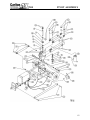
BL
Y
BIG R
FUSE BOX
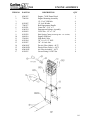
BL
SWING
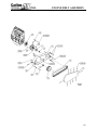
2
O
3
BK/W/R
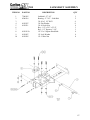
BK
ON/OFF
SWITCH
BL/BK
LEFT
RIGHT
TERMINAL BOX
Y/BK
BIG R
BL/R
5
4
BL/BK
O
OUT
O
IN
6
Y/BK
10
9
11
3
12
4
13
5
R/BK/W
DOWN
O
UP
14
6
W/R/BK
LIFT
DIODE
BL
BL
Y
R
Y/B
R
15
7
Y
BK
16
8
R/GR
O/GR
BL
BR/BK
ENGINE
DIODE
BIG BK
GR
BR
BK
O/BK
DIODE
EXT.
2
DIODE
O/BK
O/BK
DIODE
LIFT
3
DIODE
R
3
5
7
4
6
8
BK
10 9
1
2
B
O/BK
DIODE
ENLARGED VIEW
R 160
BL
A
ENGINE
CONNECTOR
BY-PASS SWITCH
ELECTRO-HYDRAULIC
CONTROLS
O/BK
SWING
1
DIODE
86
87
87A
O
(GROUND TO BOLT ON DECK)
HOUR METER
BL
Y/BK
RED FROM BREAKAWAY SWITCH
FOR ELECTRIC BRAKES
BL/BK
R/BK
R/BK
16 PIN CONNECTOR
2
1
W/R
EXT
OIL PRESS.
LIGHT
DIODE
85
RELAY
Y
30
O/BK
OIL TEMP
LIGHT
6AMP
20AMP
BL
O/BK
PRE-HEATER
40AMP
RED
ORANGE/GREEN
RED/GREEN
WHITE/RED
ORANGE/BLACK
BLUE/RED
ORANGE/RED
A6
A7
A8
A9
A10
A11
A12
PIN #
ORANGE
BLACK
ORANGE
RED
RED/BLACK
YELLOW
YELLOW/BLACK
BLUE
BLUE/BLACK
COLOR
B1
B2
B3
B4
B5
B6
B7
B8
B9
B10
B11
B12
85
=
=
=
=
=
=
=
=
=
=
=
=
=
=
=
=
=
=
=
=
=
=
=
=
RED
YELLOW
ORANGE
PURPLE
GRAY
GREEN
BLUE
BLACK
BROWN
WHITE
RED/BLACK
ORANGE BLACK
YELLOW/BLACK
YELLOW/RED
ORANGE/RED
BLUE/BLACK
BLUE/RED
BROWN/BLACK
GREEN/BLACK
BLACK/YELLOW
BLACK/BLUE
BLACK/RED
BLACK/GREEN
BLACK/BROWN
COLOR CODES
86
30
FLOW HIGH
GEAR (HIGH)
L. TRACK (FORWARD)
L. TRACK (REVERSE)
R. TRACK (FORWARD)
R. TRACK (REVERSE)
FACTORY CONFIG. ONLY
FACTORY CONFIG. ONLY
SPARE
SPARE
SPARE
SPARE
FUNCTION
OM7500-1
CHECKED BY:
PROFESSIONAL
TREE
EQUIPMENT
CURRENT
(AHF/1/11/10)
J.P. CARLTON CO. DIVISION DAF INC
Carlton
EC # 030515-H - CHG'D WIRE FROM KEY
SWITCH TO KILL SWITCH
ADDED GROUND WIRE TO 16 PIN CONNECTOR
& FROM BATTERY GROUND TO CENTRAL GROUND
EC # 030604-K - ADDED DIODES TO
CONTROLS & ADDED NOTE
EC # 041012-M - ADDED PRE-HEATER RELAY
& WIRING (WAS WIRED DIRECTLY TO KEY
SWITCH). FUSE NEXT TO 40AMP CHANGED
TO 50AMP. CHG'D JUMP WIRES TO BUS BAR.
EC # 060908-M3 - RMV'D PRE-HEATER
RELAY & WIRING; REWIRED PRE-HEATER.
(ADDED DIAGRAM BETWEEN M & P)
EC # 051128-P - REWIRED
ELECTRO-HYDRAULIC CONTROLS, REARRANGED
WIRES, & TURNED DIODES AROUND; REMOVED
PRE-HEAT RELAY; REVISED JUNCTION BOX;
TURNED ON/OFF (KILL) SWITCH AROUND.
EC # 060105-P2 - CORRECTED 16-PIN
CONNECTOR DESCRIPTION.
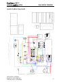
EC # 061013-R - ADDED OMNEX
CONNECTOR AND WIRING.
EC # 011110 - CHANGED NAME FROM 7500-5R
TO OM7500-1. REVISED ENGINE CONNECTOR
AND SWITCED 6AMP CIRCUIT BREAKER WITH
20 AMP CIRCUIT BREAKER. LINKED 6AMP
CIRCUIT BREAKER AND 40AMP CIRCUIT
BREAKER WITH BUSS BAR.
RED/WHITE
BLUE/WHITE
WHITE/BLACK
BLACK/RED
WHITE/RED/BLACK
RED/BLACK/WHITE
GREEN
GREEN/BLACK/WHITE
WHITE
ORANGE
PIN# COLOR
ACTUAL RELAY
CONNECTIONS
R
Y
O
PR
GY
GR
BL
BK
BR
W
R/BK
O/BK
Y/BK
Y/R
O/R
BL/BK
BL/R
BR/BK
GR/BK
BK/Y
BK/BL
BK/R
BK/GR
BK/BR
POWER IN
POWER OUT
POWER
SWING (RT)
SWING (LF)
LIFT (UP)
LIFT (DOWN)
EXTENSION (IN)
EXTENSION (OUT)
FUNCTION
SILVER SIDE OF
DIODE POINTS
AWAY FROM THE
O/BK WIRE
0/BK
1
2
3
4
5
6
7
8
9
SPARE
SPARE
GROUND
SPARE
SWITCHES TO
POWER W/LINK
POWER INPUT
LIFT (UP)
LIFT (DOWN)
SWING (R)
TRACKS (OUT)
SWING (L)
TRACKS (IN)
FUNCTION
16 PIN CONNECTOR DESCRIPTION
BLUE/BLACK
BLACK/WHITE
BLACK
GREEN/BLACK
BLACK/WHITE/RED
R160 CONNECTOR DIAGRAM
A1
A2
A3
A4
A5
PIN# COLOR
87
7500 REMOTE WIRING DIAGRAM
W/KEY SWITCH, 16-PIN CONNECTOR, R160 CONNECTOR,
BY-PASS, & PRE-HEAT
O/BK
87A
SEE RADIO CONTROL
MANUAL, INCLUDED IN
THIS MANUAL, FOR MORE
Y
7500
MACHINE WIRING
RADIO WIRING DIAGRAM
33
R
BIG BK
BIG BK
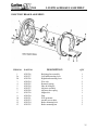
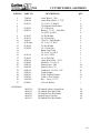
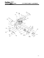
7500
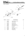
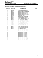
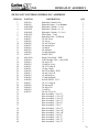
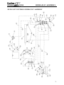
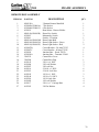
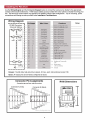
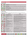
LIGHTS & BRAKES ASSEMBLY
LIGHT ASSEMBLY
ITEM NO
1
2
3
4
5
6
7
8
9
10
11
12
13
14
PART NO
0350008
0350004
0150140
0150218
0350046
3500163
0350050
0550211
0350044
0350045
0150141
0150301
0150221
7200267
DESCRIPTION
Coiled Connector Assembly
Connector Socket
1/4-20 x 3/4 HCS
1/4-20 Lock Nut
Breakaway Switch
Light Connector Bracket
1” Loom Clamp
Brake Drum w/studs & races
Tail Light Kit
Tag Light
#10 x 3/4 Machine Screw
#10 Flat Washer
#10 Lock Nut
Tail Light Bracket
QTY
1
1
4
4
1
1
3
2
2
1
4
8
4
34
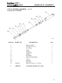
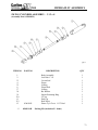
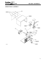
7500
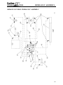
LIGHTS & BRAKES ASSEMBLY
ELECTRIC BRAKE ASSEMBLY
ITEM NO
1
2a
2b
3
4
5
6
7
8
9
10
11
12
13
PART NO
0550326
0550327
0550328
0550224
0550225
0550329
0550227
0550228
0550330
0550230
0550231
0550223
0550324
0550325
DESCRIPTION
Backing plate assembly
Left hand actuating lever
Right hand actuating lever
Wire clip
Retractor spring
Shoe & lining kit
Adjuster assembly
Adjuster shoe spring
Magnet kit
Plug
Wire grommet
Anchor post washer
Brake mounting bolt
Brake mounting nut
QTY
1
1
1
2
2
1
1
1
1
1
1
1
5
5
35
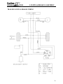
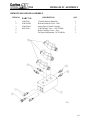
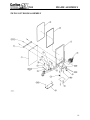
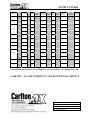
7500
LIGHTS & BRAKES ASSEMBLY
TRAILER LIGHTS & BRAKES WIRING
36
7500
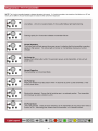
SERVICING CUTTER WHEEL
SAFETY
•
•
•
•
•
NEVER SERVICE A MACHINE WITH THE ENGINE RUNNING, SEVERE
PERSONAL INJURY COULD OCCUR. TURN ENGINE OFF THEN REMOVE
IGNITION KEY AND DISCONNECT POSITIVE BATTERY CABLE TO AVOID
STARTING MACHINE ACCIDENTALLY.
CUTTER WHEEL MUST BE DISENGAGED BEFORE TURNING ENGINE
ON/OFF AND BEFORE SERVICING A MACHINE. OTHERWISE SEVERE
PERSONAL INJURY COULD OCCUR AS WELL AS MACHINE DAMAGE.
ALL MACHINE PARTS MUST COME TO A COMPLETE STOP AND HAVE
TIME TO COOL COMPLETELY BEFORE SERVICING A MACHINE OR
SEVERE INJURY COULD OCCUR, POSSIBLY SERIOUS BURNS AND/OR
DISMEMBERMENT.
DO NOT OPERATE A MACHINE WITHOUT A COMPLETE SET OF TEETH
PROPERLY INSTALLED. EXCESSIVE MACHINE VIBRATION WILL OCCUR
CAUSING PREMATURE BEARING FAILURE AND OTHER EQUIPMENT
DAMAGE.
PLACE THE CUTTER WHEEL ON THE GROUND WHEN PERFORMING
SERVICE ON A MACHINE.
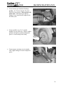
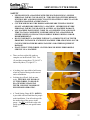
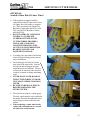
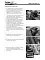
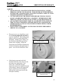
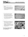
•
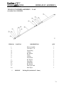
There are forty-eight (48) teeth to a
complete set on the model 7500. Two
(2) straights, twenty-three (23) left 45°’s
and twenty-three (23) right 45°’s.
•
A locking pin is provided to hold cutter
wheel in position during tooth removal
and re-installation.
Locking pin will only lock on outer
teeth. NEVER PLACE HAND ON
CUTTER WHEEL TO HOLD IN
PLACE WHILE CHANGING
TEETH. BE SURE TO REMOVE
PIN BEFORE OPERATING.
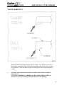
•
•
A Tooth Setting Gauge (P/N - 0450111)
is provided with each machine for proper
tooth installation. Line all teeth up with
the inside edge of the groove in the
gauge. Set ALL teeth to this edge with
gauge against pocket, not against cutter
wheel.
37
7500
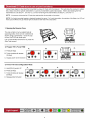
SERVICING CUTTER WHEEL
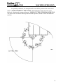
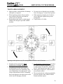
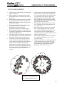
TOOTH ARRANGEMENT
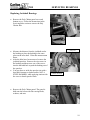
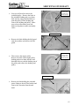
•
•
•
Inspect pockets, teeth and bolts for damage
and replace as required.
When replacing pockets, always replace
new pockets across from each other in
order to prevent vibration.
Replacement teeth must be carbide tipped
and have like design as provided with the
machine.
•
•
•
Use anti-seize on threads to prevent bolts
from “freezing up” in cutter wheel pockets.
When replacing complete set of teeth, be
sure to duplicate original factory tooth
arrangement.
Torque bolts to 150 ft/lbs.
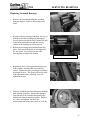
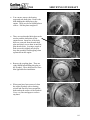
opposing outside pockets carry like arrangements of teeth to cancel vibration
•
•
Straight teeth are mounted in TWO
• Two Remaining Outside Pockets must have
45° teeth overlapping centerline of wheel
OPPOSING OUTSIDE POCKETS.
to make plunge cuts possible. Mount two
A straight tooth must have a 45° tooth
left 45° teeth opposite two right 45° teeth.
accompanying it in the same pocket set.
The opposite pocket sets should have this
• Inside pockets require 45° teeth mounted
same combination of straight and 45° teeth,
away from the wheel.
except with positions reversed. Mounting
• The second pocket in each group gradually
these teeth opposite each other on the cutter
goes back into the cutter wheel for half a
wheel cancels damaging vibration.
rotation and then repeats.
38
7500
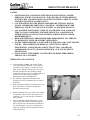
SERVICING CUTTER WHEEL
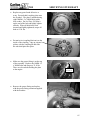
OPTIONAL:
Sandvik® Dura Disk II Cutter Wheel
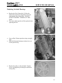
•
•
•
•
•
•
•
•
If the machine is supplied with the
optional Dura Disk II cutter wheel, there
are eighty-four (84) teeth to a complete
set. There are twenty (20) Short Plow
Bolt Bits (Carlton part #04501311) and
fifty-six (64) Plow Bolt Bits (Carlton
part #0450130).
DO NOT OPERATE A MACHINE
WITHOUT A COMPLETE
NUMBER OF TEETH IN THE
CUTTER WHEEL PROPERLY
INSTALLED. EXCESSIVE
MACHINE VIBRATION WILL
OCCUR CAUSING PREMATURE
BEARING FAILURE AND
EQUIPMENT DAMAGE.
A locking pin is provided to hold cutter
wheel in position during tooth removal
and re-installation.
The locking pin will only lock in the
deep slots of the outer teeth. Line the
slot up with the locking pin slot and
insert the pin to lock position. The pin
will need to be removed and reinserted
as wheel is rotated to change remaining
teeth.
NEVER PLACE YOUR HAND ON
THE CUTTER WHEEL TO HOLD
IT IN PLACE WHILE CHANGING
TEETH.
BE SURE TO REMOVE THE PIN
BEFORE OPERATING THE
STUMP CUTTER.
The teeth do not require a setting gauge.
The only requirement is to be installed in
the proper direction and tightened to the
proper torque as discussed in the next
section.
When replacing a cutter wheel tooth,
replace the tooth and nut as a set and
use anti-seize on the threads.
39
7500
SERVICING CUTTER WHEEL
TOOTH ARRANGEMENT
•
ROTATION
#1
#20
#2
C
LTO N
X
CAR LTO
R
CA
CA
X
OX
CA
RLTO
N
CAR
LT
L
CA
RLTO
CA R
CA
RLTO
N
CA
L
T
OX
RL
CA
N
ON
R
ON
CA RLTO
LTON
AR
LT
R
OX
TO N
RL
A
OX
X
#6
#16
C
O
X
A
OX
LT
R
X
N
TO
N
OX
L
ON
CA
L
R
LT
CA
N
RLT O
N
O
N
OX
LT
R
CA
O
OX
OX
LT
ON
OX
CA
R
CAR
C AR
CA R
L
T
T
OX
OX
ON
C
R
OX
C A RL T O
OX
TON
RL
N
N
RL
CA
R
TO
OX
C A R L TO
OX
A
#7
L
ON
TON
#15
C
T
RL
LT
CA
CA
R
CA
ON
OX
A
OX
CA
N
A
OX
C
ON
CA
CA
N
R LT O
OX
RL TO
OX
O
CA
OX
RL
O
ON
CA
ON
OX
CA
OX
LT
LT
R
RL T ON
TON
R LTON
RL
CA
R
X
T ON
ON
CA
N
RLTO
OX
ON
C
T
X
O
OX
AR
LT O N
N
OX
N
C
RL TO
TON
OX
TO
CA
OX
RL
O
C
RL
CA
ON
A
OX
CA
C
N
O
OX
N
T
X
X
TO
L
CA
R
LT
ON
N
L
#5
OX
O
O
L
N
N
C AR L TO
OX
OX
R
CA
R
X
LT
OX
O
OX
C AR
OX
N
OX
CAR
N
X
O
O
N
O
LT
OX
ON
ON
CA
T
TO
L
LT
ON
OX
LT
OX
ON
C AR
LT
T
OX
RLTO
#17
L
CAR
R
CA
#4
CAR
OX
CA
R
LT
L
TO
N
T
RL
CA
#17
TO
N
T
X
OX
C AR
CA
OX
R
L
OX
OX
R
CA
A
OX
N
C
RLTON
RL
T ON
O
N
C AR LT O
O
O
ON
N
OX
#18
N
N
CA
OX
N
CARLTO
O
O
#18
#3
A
CA
R
O
OX
#19
OX
OX
CA
RLTO
N
R
L
CA
OX
OX
O
N
OX
OX
N
ON
TO
L
LT
N
OX
CAR
CA R
T
O
#14
CA RLTO
CAR
RL
TON
OX
X
OX
X
C
A
O
O
OX
LTON
ON
AR
LT
R
X
N
C AR LTO
OX
N
RL TO
CA
CA
A
N
#12
X
It may be necessary to use a 1 1/4”
hole saw to remove debris around
nut to make tooth removal easier.
X
N
#9
#13
C
RLTO
C
LT
AR
TO
O
AR
LT ON
CA
C
L
O
#8
LT
N
CA
R
C
•
•
LTON
•
R
•
•
OX
•
•
N
•
Outside pocket teeth are Short Plow Bolt Bits.
These pockets are angled and welded in place.
You can switch teeth from one outside pocket
to a pocket that is the opposite direction to
prolong tooth life, such as switching a tooth
from a 20 R with a tooth from a 20 L pocket.
The cutting edge is the corner and this will turn
the opposite corner out for use.
These teeth are tightened with a Stover Lock
Nut. Torque on Stover locking nuts is not to
exceed 270 ft/lbs.
All teeth on cutter wheel sides are Plow Bolt
Bits. When changing these teeth you must
remove both teeth in the same pocket, one on
each side of the wheel. When the nuts are
torqued, the pocket is jammed and the teeth can
only be removed this way.
These teeth are tightened with a Locking Jam
Nut. Torque on locking jam nuts is not to
exceed 128 ft/lbs.
The pocket will receive wear when cutting and
can be switched from one side of the cutter
wheel to the other to prolong life. Remember
the teeth must be replaced in the original
position on each side of the wheel.
TO
•
•
Inspect pockets, teeth and nuts for damage and
replace as required.
When replacing a cutter wheel tooth, replace
the tooth and nut as a set and use anti-seize on
the threads.
When replacing teeth and pockets, also replace
the teeth and pockets across from each other
diagonally in order to maintain wheel balance
and prevent vibration.
All teeth and pockets are of a specific design
and must be replaced with original
manufacturer’s replacement parts.
Replacement teeth must be carbide tipped.
When replacing complete set of teeth, be sure
to duplicate original factory tooth arrangement.
SEE DIAGRAM BELOW.
The seating surfaces of the tooth and pocket are
formed, but make sure the tooth is inserted with
the carbide facing the direction of rotation.
The pictured view is the engraved side of the
wheel. The wheel is engraved with outside
pocket numbers, outside pocket angle/direction
(20 R or 20 L), and wheel rotation. (The
engraved side of wheel is marked left side of
wheel; this is for manufacturing purposes only.
It does not refer to the left side of the machine
as described in the General Information
section.)
L
•
RL
TON
C
OX
AR
L TO N
O
#11
#10
CARLTON SP7500 TRIUMPTH MANUAL
40
7500
SERVICING CUTTER WHEEL
TOOTH SHARPENING
Begin by chamfering shank back past edge of carbide. You do this because if it is
not back far enough the shank will hit the stump and not the carbide, thus causing a
lot of vibration. Once the shank is angled far enough back, then begin sharpening
carbide.
•
Cut shank with a standard rock and cut carbide with a silicone carbide or
diamond rock.
CAUTION: GRINDING CARBIDE CAN BE A HEALTH HAZARD. Use
facemask to prevent breathing in harmful material while grinding.
41
7500
SERVICING HYDRAULICS
SAFETY
• NEVER SERVICE A MACHINE WITH THE ENGINE RUNNING, SEVERE
PERSONAL INJURY COULD OCCUR. TURN ENGINE OFF THEN REMOVE
IGNITION KEY AND DISCONNECT POSITIVE BATTERY CABLE TO AVOID
STARTING MACHINE ACCIDENTALLY.
• CUTTER WHEEL MUST BE DISENGAGED BEFORE TURNING ENGINE
ON/OFF AND BEFORE SERVICING A MACHINE. OTHERWISE SEVERE
PERSONAL INJURY COULD OCCUR AS WELL AS MACHINE DAMAGE.
• ALL MACHINE PARTS MUST COME TO A COMPLETE STOP AND HAVE
TIME TO COOL COMPLETELY BEFORE SERVICING A MACHINE OR
SEVERE INJURY COULD OCCUR, POSSIBLY SERIOUS BURNS AND/OR
DISMEMBERMENT.
• RELEASE HYDRAULIC PRESSURE BEFORE PERFORMING ANY SERVICE
TO HYDRAULIC LINES OR OTHER COMPONENTS.
• FLUID UNDER PRESSURE CAN PENETRATE THE SKIN AND CAUSE SEVERE
INJURY. SEEK IMMEDIATE MEDICAL ATTENTION IF SKIN IS
PENETRATED. CHECK HOSES AND FITTINGS USING A BOARD OR
CARDBOARD; DO NOT USE HAND OR FINGER. ALWAYS WEAR EYE
PROTECTION.
• PLACE THE CUTTER WHEEL ON THE GROUND WHEN PERFORMING
SERVICE ON A MACHINE.
HYDRAULIC OIL & FILTER
•
•
•
•
•
Check hydraulic oil daily, with engine off and
cool, and replenish as necessary. A site glass is
provided for easy viewing. If oil can be seen in
glass, there is enough oil in the tank. Do not fill
the tank more than 7/8 full; operating at high
temperature will cause oil to expand and spill over
if tank is full. Tank capacity is 9 gallons.
Remember to replace and tighten cap.
The machine is equipped with Citgo AW32
hydraulic oil at time of manufacture; use same or
equivalent.
Drain and replace hydraulic oil at least once a year,
more often if oil is very dark or smells burnt.
Discard used oil properly.
Replace hydraulic filter every three to four months
of normal use. More often if used under severe
conditions. Use a 10-micron filter, available at
most locations.
Unscrew old filter and discard properly. Clean
filter housing and install new filter, making sure
old O-ring has been removed and new filter has a
new O-ring in place. Screw in new filter hand
tight only. Recheck oil level and refill if needed,
as described above.
42
7500
SERVICING HYDRAULICS
REPLACING ROD ENDS
•
•
Should a rod end need replacing, loosen
through bolt clamping rod end to cylinder
rod and unscrew rod end.
Reverse process to install new rod end.
Tighten through bolt and use new cotter
pins, and cylinder pins.
REPLACING BUSHINGS
•
•
•
•
Hardened bushings have been incorporated
into the machine to protect the main frame
from wear and damage.
Should a bushing need replacing, disconnect
rod end from main frame and swing cylinder
out of the way.
Position new bushing directly above old
bushing and gently tap new bushing down
into position, displacing old bushing in the
process.
Swing cylinder back into position. Reinstall rod end to main frame, using new pin
assemblies.
REPLACING HYDRAULIC PUMP
•
•
•
•
•
•
•
Engine must be shut off.
Remove key & disconnect battery cable.
Make sure that hydraulic oil is cool and that
pressure is relieved from the lines.
Disconnect hydraulic lines from pump and
cap them.
Remove bolts holding pump to engine.
Replace pump and tighten bolts.
Recheck oil supply in reservoir.
REPLACING HYDRAULIC HOSES
•
•
•
•
It is not necessary to drain the hydraulic
system to replace hoses.
Loosen fitting and drain oil into suitable
container for disposal. Remove old hose
and replace with new one.
Tighten fittings.
Check for adequate supply of oil in tank
before operating machine.
43
7500
SERVICING BOOM PIVOT
SAFETY
•
•
•
•
NEVER SERVICE A MACHINE WITH THE ENGINE RUNNING, SEVERE
PERSONAL INJURY COULD OCCUR. TURN ENGINE OFF THEN REMOVE
IGNITION KEY AND DISCONNECT POSITIVE BATTERY CABLE TO AVOID
STARTING MACHINE ACCIDENTALLY.
CUTTER WHEEL MUST BE DISENGAGED BEFORE TURNING ENGINE
ON/OFF AND BEFORE SERVICING A MACHINE. OTHERWISE SEVERE
PERSONAL INJURY COULD OCCUR AS WELL AS MACHINE DAMAGE.
ALL MACHINE PARTS MUST COME TO A COMPLETE STOP AND HAVE
TIME TO COOL COMPLETELY BEFORE SERVICING A MACHINE OR
SEVERE INJURY COULD OCCUR, POSSIBLY SERIOUS BURNS AND/OR
DISMEMBERMENT.
PLACE THE CUTTER WHEEL ON THE GROUND WHEN PERFORMING
SERVICE ON A MACHINE.
POP-OUT VALVE
•
Swing boom to the left to get to the boom
pivot grease fitting. Grease boom pivot
monthly. Do Not Over Grease. There is a
Pop-Out Valve above the grease fitting, if
the pin pops out enough grease has been
applied. Wipe off excess grease. Excess
grease will attract dirt.
•
The boom pivot is equipped with a hardened
shaft and Timken roller bearings. If the
boom becomes loose, you will need to apply
pressure to the bearings to tighten it. To
apply more pressure to the bearings, hold the
bottom nut where the cotter pin is. Remove
the top nut and tighten the second nut, which
will apply pressure to the roller bearings and
the boom swing. You can place cutter
wheel on ground and put slight pressure on
cutter wheel to adjust pivot bearings.
If for some reason you need to replace the main pivot bearings, you will have to remove the top
pin and slide the main pivot out and install the new bearings.
•
Boom must be placed in a fixture to hold steady when you remove the pivot pin. (SEE
PIVOT ASSEMBLY FOR BREAKDOWN)
44
7500
SERVICING BELTS
Replacing V-Belt
SAFETY
•
•
•
•
NEVER SERVICE A MACHINE WITH THE ENGINE RUNNING, SEVERE
PERSONAL INJURY COULD OCCUR. TURN ENGINE OFF THEN REMOVE
IGNITION KEY AND DISCONNECT POSITIVE BATTERY CABLE TO AVOID
STARTING MACHINE ACCIDENTALLY.
CUTTER WHEEL MUST BE DISENGAGED BEFORE TURNING ENGINE
ON/OFF AND BEFORE SERVICING A MACHINE. OTHERWISE SEVERE
PERSONAL INJURY COULD OCCUR AS WELL AS MACHINE DAMAGE.
ALL MACHINE PARTS MUST COME TO A COMPLETE STOP AND HAVE
TIME TO COOL COMPLETELY BEFORE SERVICING A MACHINE OR
SEVERE INJURY COULD OCCUR, POSSIBLY SERIOUS BURNS AND/OR
DISMEMBERMENT.
PLACE THE CUTTER WHEEL ON THE GROUND WHEN PERFORMING
SERVICE ON A MACHINE.
•
Remove front cover of engine belt guard, which is
held on with ten bolts.
•
Move engine back toward cutter wheel as far as it
will go by disengaging cutter wheel as shown at
right. This will remove tension from the belt and
allow you to remove and replace the engine belt.
The engine slide lock should automatically move
into position when the engine is disengaged, make
sure that it is locked.
•
ENGAGED
ENGINE SLIDE LOCK
•
DISENGAGED
Remove the belt keeper at the jackshaft pulley for
easier belt removal.
REMOVE THIS BELT KEEPER
45
7500
SERVICING BELTS
Replacing V-Belt
•
•
Remove and replace the engine belt.
If you have difficulty replacing the new belt, you
may need to relieve some of the tension that was
applied to the old belt. Read the information on
adjusting tension below and loosen the belt tension.
•
After replacing the V-belt, check the tension.
Engage the belt by sliding the engine forward
(reference engaged position on previous page).
The belt should deflect 3/8” with 25 lbs. of force
applied to the center of the belt between the
sheaves. New belts will stretch and become loose
as machine runs. Check and adjust belt tension
often when belts are new.
If any adjustment is required, there is a linkage
assembly below the engagement handle on the
operator side. Loosen jam nut and adjust clevis
with wrench turning up toward machine. This will
make engine slide further and will tighten the belt.
Make only slight adjustments at a time and recheck
tension; repeat as necessary until tension is correct.
Once proper tension is achieved, tighten jam nut
back onto clevis.
Use this same procedure to tighten loose belts.
DO NOT OVER TIGHTEN BELT; OVERLY
TIGHT BELTS WILL CAUSE BEARING AND
ENGINE DAMAGE. Turn the clevis in the
opposite direction to loosen belt tension.
Replace belts when worn or when repeated
adjustments are necessary. Belts should never get
so loose that all of the adjustment capability is
used.
•
•
•
•
•
JAM NUT
CLEVIS
Replace the belt keeper at the jackshaft pulley.
REPLACE THE BELT KEEPER
46
7500
SERVICING BELTS
Replacing V-Belt
•
•
•
When adjusting engine belt tension, you will also
have to adjust the engine slide stop. Shorten
engine slide handle as you lengthen the linkage
assembly.
Loosen the jam nut and turn the handle one turn
and check to see if the engine is locked in the
disengaged position. Make more adjustments, if
necessary, until the engine is locked in the
disengaged position. Then retighten the jam nut.
Replace V-belt guard cover and tighten the bolts.
DO NOT RUN MACHINE WITHOUT ALL
GUARDS IN PLACE AND SECURED.
GENERAL TENSIONING OF V-BELT DRIVES
Tensioning of belts on a V-belt drive is usually not critical. A few simple rules about tensioning
will satisfy most of your requirements:
1. The best tension for the V-belt drive is
the lowest tension at which the belts will
not slip under the highest load condition.
2. Check the tension on a new drive
frequently during the first day of
operation.
3. Thereafter, check the drive tension
periodically.
4. Too much tension shortens belt and
bearing life.
5. Keep belts and sheaves free from any
foreign material that may cause slippage.
47
7500
SERVICING BELTS
Replacing Poly Chain® Belt
SAFETY
•
•
•
•
•
NEVER SERVICE A MACHINE WITH THE ENGINE RUNNING, SEVERE
PERSONAL INJURY COULD OCCUR. TURN ENGINE OFF THEN REMOVE
IGNITION KEY AND DISCONNECT POSITIVE BATTERY CABLE TO AVOID
STARTING MACHINE ACCIDENTALLY.
CUTTER WHEEL MUST BE DISENGAGED BEFORE TURNING ENGINE
ON/OFF AND BEFORE SERVICING A MACHINE. OTHERWISE SEVERE
PERSONAL INJURY COULD OCCUR AS WELL AS MACHINE DAMAGE.
ALL MACHINE PARTS MUST COME TO A COMPLETE STOP AND HAVE
TIME TO COOL COMPLETELY BEFORE SERVICING A MACHINE OR
SEVERE INJURY COULD OCCUR, POSSIBLY SERIOUS BURNS AND/OR
DISMEMBERMENT.
PLACE THE CUTTER WHEEL ON THE GROUND WHEN PERFORMING
SERVICE ON A MACHINE.
DO NOT OPERATE A MACHINE WITHOUT A COMPLETE SET OF TEETH
PROPERLY INSTALLED. EXCESSIVE MACHINE VIBRATION WILL OCCUR
CAUSING PREMATURE BEARING FAILURE AND OTHER EQUIPMENT
DAMAGE.
Special care needs to be taken with your Poly Chain® belt. Alignment, tension, and cleanliness
of this belt are very important. The Poly Chain® belt needs to be checked for tension
approximately every 70 to 100 hours of use. The Poly Chain® belt must be running true. If you
adjust one bearing more than the other, the belt will run on an angle and will cause belt failure.
If a belt is broken straight across, this is the result of a shock load. Lost teeth on the belt are an
indication that the belt was loose. When replacing the Poly Chain® belt, do not try to pry belt on
over sprocket, this can break the fibers in the Poly Chain® belt. After you have installed or retensioned the Poly Chain® belt, you will have to re-adjust the engine belt for proper tension
•
Remove the Poly Chain® guard cover and
bottom cover. The cutter wheel must be
disengaged. (See the Machine Control section
for more information.)
•
Loosen, do not remove, the nuts on the bolts
that are holding the belt guard to the machine.
48
7500
SERVICING BELTS
Replacing Poly Chain® Belt
•
Loosen Poly Chain® belt by moving jackshaft
bearings back toward rear of machine. MARK
THE JACKSHAFT BEARINGS SO THAT
YOU KNOW WHERE THEY ARE
POSITIONED ON THE JACKSHAFT
PLATE. Loosen, do not remove, the four bolts
that hold the jackshaft bearings down.
•
Loosen the jam bolts in the back and move the
bearings toward cutter wheel.
•
Place a mark on the cutter wheel shaft next
to the cutter wheel bushing for replacing the
bushing and sprocket.
When the belt has been loosened, remove the
cutter wheel sprocket. Remove the three screws
in the bushing and then screw two of the screws
into the two threaded holes to push the bushing
out of the sprocket. Turn one screw a small
amount and then turn the other screw the same
amount to keep from damaging the bushing or
sprocket, work back and forth until the sprocket
is loose.
You may have to strike the sprocket rim with a
dead blow hammer or leather mallet, NOT A
STEEL HAMMER, while applying tension with
the two screws to break sprocket loose.
•
•
REPLACE SCREWS IN THREADED HOLES TO
REMOVE BUSHING
MAKE A MARK ON THE CUTTER WHEEL SHAFT
TO REPLACE THE BUSHING AND SPROCKET
49
7500
SERVICING BELTS
Replacing Poly Chain® Belt
•
•
•
•
•
•
Remove old belt and replace with new one.
Replace the belt over the jackshaft sprocket
first. Put the cutter wheel sprocket and the Poly
Chain® belt on the cutter wheel shaft at the
same time, with the sprocket inside the belt.
Put the cutter wheel tapered bushing on the
cutter wheel shaft and inside the sprocket. Push
the bushing as close to the position you marked
earlier as possible. Replace and tighten the
screws. Torque screws to 67 ft. lbs.
Tighten the belt by sliding the jackshaft
bearings back into the place that you had
marked on the jackshaft plate earlier. If the old
Poly Chain® belt had the tension adjusted, you
may not be able to get the bearing to move back
to the position marked earlier. Don’t try to
force the bearings back into that position or you
may damage the new belt.
Tighten the jam bolts.
Check belt alignment using a straight edge.
Adjust belt alignment by loosening one
jackshaft bearing jam bolt and tightening the
other bearings jam bolt. Make only slight
adjustments and recheck alignment. The
alignment and tension of the V-belt will also
need to be checked after changing and
adjusting the Poly Chain® belt.
50
7500
SERVICING BELTS
Replacing Poly Chain® Belt
•
•
•
•
To tighten the belt more if needed, loosen the
front bolts and tighten each of the back jam
bolts the same number of revolutions, to keep
the alignment true. Make only slight
adjustments at a time and recheck tension;
repeat as necessary until tension is correct.
Then once the belt is adjusted, tighten the front
bolts against the bearing. Recheck belt
alignment after tightening all bolts and nuts to
make sure the belt is sill aligned.
Use this same procedure to tighten loose belts.
DO NOT OVER TIGHTEN BELT; OVERLY
TIGHT BELTS WILL CAUSE BEARING
AND ENGINE DAMAGE. To loosen the
tension on a belt, loosen the jam bolt and tighten
the bolt on the other side of the bearing.
Always make slight, equal adjustments on both
bearings and recheck tension.
Replace belts when worn or when repeated
adjustments are necessary. Belts should never
get so loose that all of the adjustment capability
is used.
•
Retighten the bolts in the jackshaft bearings
when the tension is adjusted properly.
•
Retighten the bolts and nuts that are holding the
belt guard to the machine.
•
Replace belt guard cover and bottom. Tighten
the bolts. DO NOT RUN MACHINE
WITHOUT ALL GUARDS IN PLACE AND
SECURED.
51
7500
SERVICING BELTS
Replacing Poly Chain® Belt
52
7500
SERVICING BEARINGS
Replacing Jackshaft Bearings
SAFETY
•
•
•
•
NEVER SERVICE A MACHINE WITH THE ENGINE RUNNING, SEVERE
PERSONAL INJURY COULD OCCUR. TURN ENGINE OFF THEN REMOVE
IGNITION KEY AND DISCONNECT POSITIVE BATTERY CABLE TO AVOID
STARTING MACHINE ACCIDENTALLY.
CUTTER WHEEL MUST BE DISENGAGED BEFORE TURNING ENGINE
ON/OFF AND BEFORE SERVICING A MACHINE. OTHERWISE SEVERE
PERSONAL INJURY COULD OCCUR AS WELL AS MACHINE DAMAGE.
ALL MACHINE PARTS MUST COME TO A COMPLETE STOP AND HAVE
TIME TO COOL COMPLETELY BEFORE SERVICING A MACHINE OR
SEVERE INJURY COULD OCCUR, POSSIBLY SERIOUS BURNS AND/OR
DISMEMBERMENT.
PLACE THE CUTTER WHEEL ON THE GROUND WHEN PERFORMING
SERVICE ON A MACHINE.
In all Carlton® model Stump Grinders, you will find link belt bearings that are made to be
purged with grease. It is necessary to purge these bearings everyday until clean grease is seen.
CAUTION should be taken not to allow grease to build up inside the belt guards.
•
Remove the V-belt guard cover. Follow
instructions in the Servicing Belts section for
removing the engine belt.
•
Remove the jackshaft pulley. Remove the bolts
from the bushing and use them to screw into the
threaded holes in the bushing. Turn one bolt
only a slight amount and then turn the next bolt
the same amount. Work back and forth turning
the bolts in equal amounts until the bushing is
pushed out of the jackshaft pulley.
53
7500
SERVICING BEARINGS
Replacing Jackshaft Bearings
•
Remove the Poly Chain® guard cover and
bottom cover. Follow the instructions in the
Servicing Belts section to remove the Poly
Chain® belt.
•
Measure the distance from the jackshaft end to
the bushing to place the bushing in the same
place on the new shaft. Write this measurement
down.
After the belts have been removed, remove the
jackshaft sprocket. Remove the two screws in
the bushing and then screw one of the screws
into the threaded hole to push the bushing out of
the sprocket.
You may have to strike the sprocket rim with a
dead blow hammer or leather mallet, NOT A
STEEL HAMMER, while applying tension with
the screw to break sprocket loose.
•
•
•
SPROCKET
TAPERED BUSHING
Remove the Poly Chain® guard. The guard is
held onto the boom with four carriage bolts,
washers, and nuts.
54
7500
SERVICING BEARINGS
Replacing Jackshaft Bearings
•
Remove the four bolts holding the jackshaft
bearings in place. Remove old bearings and
shaft.
•
Replace with new bearings and shaft. Be sure to
turn the end of the jackshaft with the longest
keyway pocket toward the Poly Chain® belt side
of the boom and make sure that the locking
collars on the bearings are facing inward.
Bolt the new bearings and jackshaft back into
place. Just snug bolts down, do not tighten all
the way down, you will need to move the
bearings later to adjust belt tension.
•
BEARING COLLARS FACING INWARD
•
Replace the Poly Chain® guard and replace the
bolts, washers, and nuts that were removed
earlier. Tighten the bolts just enough to hold the
belt guard in place. The guard will need to slide
with adjustment of the jackshaft. You will
tighten these later.
•
Place the jackshaft sprocket and tapered bushing
back onto the jackshaft. Measure the distance
from the end of the jackshaft and position the
bushing the distance measured earlier. Replace
the screws and tighten. Recheck the
measurement and torque the screws to 36 ft. lbs.
55
7500
SERVICING BEARINGS
Replacing Jackshaft Bearings
•
•
•
•
•
Replace the Poly Chain® belt. Follow the
instructions in the Servicing Belts section for
replacing the Poly Chain® belt. DO NOT
ADJUST THE BELT TENSION AT THIS
TIME.
The cutter wheel sprocket will be replaced when
replacing the belt.
Line up Poly Chain® sprockets using a straight
edge.
Slide shaft through bearings to adjust in or out
to line sprockets up.
Replace the pulley on the jackshaft. Replace
screws, turning them just enough to start them
in the pulley.
56
7500
SERVICING BEARINGS
Replacing Jackshaft Bearings
•
•
•
•
•
•
•
Line the jackshaft pulley up with the engine
pulley using a straight edge.
When the pulleys are aligned, tighten the screws
in the jackshaft pulley. Recheck the alignment
to be sure nothing changed. Torque the screws
in the jackshaft pulley to 30 ft. lbs
Once the sprockets are lined up, tighten Poly
Chain® belt by adjusting jam bolts on the
jackshaft bearings. Remember at this point
everything is lined up, so when you adjust one
bearing forward, adjust the other bearing the
same amount.
Make only slight adjustments at a time and
recheck tension; repeat as necessary until
tension is correct. Then once the belt is
adjusted, retighten the bolts on the other side of
the bearings. Recheck belt alignment after
tightening all bolts and nuts to make sure the
belt is sill aligned.
DO NOT OVER TIGHTEN BELT; OVERLY
TIGHT BELTS WILL CAUSE BEARING
AND ENGINE DAMAGE. To loosen the
tension on a belt, loosen the jam bolts and
tighten the bolts on the other side of the bearing.
Always make slight adjustments and recheck
tension. Also make equal adjustments on both
bearings.
Replace belts when worn or when repeated
adjustments are necessary. Belts should never
get so loose that all of the adjustment capability
is used.
Tighten bearings down and recheck Poly
Chain® sprocket alignment and tension. Use
two wrenches to tighten the bolts in the bearings
as shown in the picture to the right.
57
7500
SERVICING BEARINGS
Replacing Jackshaft Bearings
•
There are two setscrews in each bearing lock
collar. Tighten one setscrew in each collar and
remove the other setscrew. Punch a start point
in the shaft and drill 3/8” diameter hole in
jackshaft just deep enough for setscrew to enter
shaft. Take care not to damage the screw
threads. Replace setscrew with LocTite 242
and tighten. Do this for all four setscrews. This
will help prevent shaft from spinning and
walking inside of bearing.
•
Finish tightening the nuts on the carriage bolts
holding the Poly Chain® belt guard in place.
Replace Poly Chain® belt guard cover and
bottom cover. Tighten the bolts. DO NOT
RUN MACHINE WITHOUT ALL GUARDS
IN PLACE AND SECURED PROPERLY.
•
•
Replace V-belt and check tension. Reference
Servicing Belts section for information on
checking and adjusting V-belt tension.
•
Replace engine belt guard cover. Tighten the
bolts. DO NOT RUN MACHINE WITHOUT
ALL GUARDS IN PLACE AND SECURED
PROPERLY.
58
7500
SERVICING BEARINGS
Replacing Cutter Wheel Bearings
SAFETY
•
•
•
•
•
NEVER SERVICE A MACHINE WITH THE ENGINE RUNNING, SEVERE
PERSONAL INJURY COULD OCCUR. TURN ENGINE OFF THEN REMOVE
IGNITION KEY AND DISCONNECT POSITIVE BATTERY CABLE TO AVOID
STARTING MACHINE ACCIDENTALLY.
CUTTER WHEEL MUST BE DISENGAGED BEFORE TURNING ENGINE
ON/OFF AND BEFORE SERVICING A MACHINE. OTHERWISE SEVERE
PERSONAL INJURY COULD OCCUR AS WELL AS MACHINE DAMAGE.
ALL MACHINE PARTS MUST COME TO A COMPLETE STOP AND HAVE
TIME TO COOL COMPLETELY BEFORE SERVICING A MACHINE OR
SEVERE INJURY COULD OCCUR, POSSIBLY SERIOUS BURNS AND/OR
DISMEMBERMENT.
DO NOT OPERATE A MACHINE WITHOUT A COMPLETE SET OF TEETH
PROPERLY INSTALLED. EXCESSIVE MACHINE VIBRATION WILL OCCUR
CAUSING PREMATURE BEARING FAILURE AND OTHER EQUIPMENT
DAMAGE.
PLACE THE CUTTER WHEEL ON THE GROUND WHEN PERFORMING
SERVICE ON A MACHINE.
In all Carlton® model Stump Grinders, you will find link belt bearings that are made to be
purged. It is necessary to purge these bearings everyday until clean grease is seen. CAUTION
should be taken not to allow grease to build up inside the belt guards.
•
Remove the Poly Chain® belt guard cover and
bottom cover. See the Servicing Belts section to
remove the Poly Chain® belt and cutter wheel
sprocket.
•
Remove the four bolts on the cutter wheel
bearings. The cutter wheel will be free from the
machine at this point. With the Poly Chain®
belt removed, you can start the machine and
raise the boom up.
59
7500
SERVICING BEARINGS
Replacing Cutter Wheel Bearings
•
•
•
•
•
•
Loosen the setscrews in the locking collars of
the bearings. You may need to heat bearing
collar to loosen the LocTite that was used
during assembly.
To remove the bearings from the cutter wheel
shaft, use a steel hammer to strike the bearing
housing until it cracks and breaks apart. Then
use a torch to cut the bearing race off the shaft.
Be very careful not to cut into the cutter wheel
shaft with the torch. Allow the shaft to cool
completely before starting to reassemble the
new bearings.
Replace new bearings making sure the lock
collars on the bearings are facing inward toward
the cutter wheel.
BEARING COLLARS FACING IN
There are two setscrews in each bearing lock
collar. Tighten one setscrew in each collar and
remove the other setscrew. Punch a start point
in the shaft and drill 3/8” diameter hole in cutter
wheel shaft just deep enough for setscrew to
enter shaft. Take care not to damage the
screw threads. Replace setscrew with LocTite
242 and tighten. Do this for all four setscrews.
This will help prevent shaft from spinning and
walking inside of bearing.
Note: if you are only replacing the bearings and
not the cutter wheel shaft, you do not have to
drill the points into the shaft. Just make sure to
line the holes in the collar up with the holes in
the cutter wheel shaft.
Bolt bearings and cutter wheel back to boom
box. Tighten the bolts. There are two nuts on
each bolt.
60
7500
SERVICING BEARINGS
Replacing Cutter Wheel Bearings
•
Replace the Poly Chain® belt. Follow the
instructions in the Servicing Belts section for
replacing and tensioning the Poly Chain® belt.
NOTE: Refer to SERVICING BELTS section for proper installation and tensioning of all belts.
(Alignment and tension of Poly Chain® belt is very important. See information on alignment
using straight edge in Replacing Jackshaft Bearings section of manual.)
•
After belt has been replaced and properly
adjusted, replace guard cover and end. Tighten
the bolts. DO NOT RUN MACHINE
WITHOUT ALL GUARDS IN PLACE AND
SECURED PROPERLY.
61
7500
SERVICING STUB SHAFT
SAFETY
•
•
•
•
•
•
NEVER SERVICE A MACHINE WITH THE ENGINE RUNNING, SEVERE
PERSONAL INJURY COULD OCCUR. TURN ENGINE OFF THEN REMOVE
IGNITION KEY AND DISCONNECT POSITIVE BATTERY CABLE TO AVOID
STARTING MACHINE ACCIDENTALLY.
CUTTER WHEEL MUST BE DISENGAGED BEFORE TURNING ENGINE
ON/OFF AND BEFORE SERVICING A MACHINE. OTHERWISE SEVERE
PERSONAL INJURY COULD OCCUR AS WELL AS MACHINE DAMAGE.
ALL MACHINE PARTS MUST COME TO A COMPLETE STOP AND HAVE
TIME TO COOL COMPLETELY BEFORE SERVICING A MACHINE OR
SEVERE INJURY COULD OCCUR, POSSIBLY SERIOUS BURNS AND/OR
DISMEMBERMENT.
PLACE THE CUTTER WHEEL ON THE GROUND WHEN PERFORMING
SERVICE ON A MACHINE.
The most service you should have to do
for the bearing supported stub shaft is
to grease it properly. The bearing grease
fitting is easily accessible behind the Vbelt guard. Another grease fitting is on
the end of the stub shaft to grease the
splines in the coupling. Follow the
instructions in the Machine Maintenance
section for frequency and application of
grease. Also see the Lubrication Chart.
BEARING SUPPORTED STUB SHAFT
GREASE FITTINGS
If the bearing supported stub shaft
should fail for any reason, these are the
procedures for replacement. First
remove the V-belt following the
instructions in the Servicing Belt Section
of the manual. Remove the engine belt
keepers instead of just loosening the
bolts and lay aside to put on new stub
shaft plate assembly.
REMOVE V-BELT GUARD COVER
AND FOLLOW INSTRUCTIONS FOR
REMOVING V-BELT.
62
7500
•
SERVICING STUB SHAFT
REMOVE
BOLTS AND
SCREW INTO
EXTRA HOLES
Next you will need to remove the
jackshaft pulley. Remove the bolts in
the jackshaft bushing and screw them
back into the empty threaded holes to
push the pulley off the bushing and
remove the bushing and pulley. Make
sure to keep all machine parts and
hardware together to make reassembly
easier.
REMOVE BOLTS
•
•
Remove the bolts holding the belt guard
onto the machine and remove the belt
guard.
REMOVE
BOLTS AND
SCREW INTO
EXTRA HOLES
Then remove the engine pulley.
Remove the bolts in the engine pulley
bushing and screw them into the extra
threaded holes to push the bushing out of
the pulley and remove the bushing and
pulley.
REMOVE BOLT
•
Remove the bolt holding the extended
grease fitting to the air filter bracket and
remove the extension from the stub
shaft.
63
7500
•
You can now remove the bearing
supported stub shaft plate. Remove the
bolts holding the shaft plate to the
engine. There are eleven 10MM bolts to
remove. Pull the plate straight off.
•
There are two threaded holes that can be
used to push the shaft plate off the
engine mount. Insert two of the bolts
that were removed from the stub shaft
plate and slowly screw them in until the
plate breaks loose. Leaving a couple of
bolts screwed in slightly may help to
keep the assembly from dropping when
separated from the engine.
•
Remove the coupling plate. There are
eight 10MM bolts holding this plate to
the flywheel. These bolts had LocTite®
blue applied before installation.
•
When parts have been removed, clean
the engine flywheel with a cleaning
solvent and check for burrs around the
holes and on the surface of the flywheel.
Use a very fine sand paper to remove
any burrs.
SERVICING STUB SHAFT
64
7500
•
Replace any parts found defective or
worn. Put stub shaft coupling plate onto
the flywheel. The plate is attached using
eight 10MM-1.5 x 20MM bolts with a
lock washer. Put LocTite® 242 (blue)
on the end of the bolt and lightly tighten
all bolts. When all bolts have been
inserted and lightly tightened, torque all
bolts to 35 ft. lbs.
•
Put anti-seize (coupling lubricant) on the
inside of the coupling. Line up external
splines with the coupling ID and slide
the stub shaft plate into place.
•
Make sure the grease fitting is on the top
of the assembly. Replace the 10MM-1.5
x 30MM bolts and torque to 35 ft. lbs.
There are eleven bolts holding the plate
to the engine.
•
SERVICING STUB SHAFT
GREASE
FITTING UP
Remove the grease fitting and replace
with the grease fitting extension supplied
with the machine.
65
7500
•
•
SERVICING STUB SHAFT
Bolt grease fitting to the air filter
bracket.
Before starting the engine, apply grease
to the grease fitting until the pin on the
opposite side of the stub shaft pops out
(see Machine Maintenance section for
more information).
•
Start replacing parts in the opposite
order in which they were removed.
Replace the V-belt guard and then
replace the engine and jackshaft pulleys.
Torque the bolts in the pulleys to 30 ft.
lbs. It will be easier to bolt the belt
keepers onto the stub shaft plate before
you put the engine pulley on.
•
Replace the V-belt and align the pulleys
as instructed in the Servicing Belt
Section of the manual. Adjust pulleys as
necessary to get the proper belt
alignment. Check belt tension and set as
described in Servicing Belt section. Belt
alignment and tension are very important
for long bearing life.
DO NOT RUN MACHINE WITHOUT
ALL GUARDS IN PLACE AND
SECURED PROPERLY.
66
7500
HYDRAULIC ASSEMBLY
REMOTE CONTROL HYDRAULIC ASSEMBLY
ITEM NO
1
2
3
4
5
6
7
8
9
10
11
12
13
14
15
16
17
18
19
20
21
22
23
24
25
26
27
28
29
PART NO
0300150A
0300142
0300105H
0300105L
0300105J
0300135C
0300135
0300220
0300218
0300234
0300245
0300205
0300236
0300217
0300237
0300215
0300238
0300239
DESCRIPTION
3 Station Remote Manifold
Hydraulic Pump - Tow Behinds
Hydraulic Cylinder - 3 x 60
Hydraulic Cylinder - 4 x 12
Hydraulic Cylinder - 3 1/2 x 8
Filter Head – 1 psi
Hydraulic Filter - 10 Micron
3/4MP-3/4MP90 - 5500-12
3/4JIC-3/4MP90 - 2501-12-12
3/4 JIC - 3/4 ORB - 6400-12
1/2 JIC-5/8ORB - 6400-8-10
3/8 MJIC- 3/8ORB90 - 6801-6
1/2 JIC-1/2 ORB- 6400-8
1/2JIC-3/4MP90 - 2501-8-12
3/8 JIC-3/8 ORB - 6400-6-6
3/8JIC-1/2MP90 - 2501-6-8
3/8 JIC - 1/2 MP - 2404-6-8
1/4 ORB Plug - 6408-4
Hose Assembly - 3/8 x 20”
Hose Assembly - 3/8 x 28”
Hose Assembly - 3/8 x 60”
Hose Assembly - 3/8 x 46”
Hose Assembly - 3/8 x 80”
Hose Assembly - 3/8 x 82”
Hose Assembly - 3/8 x 93”
Hose Assembly - 3/8 x 70”
Hose Assembly - 1/2 x 90”
Hose Assembly - 1/2 x 124”
Hose Assembly - 3/4 x 51”
QTY
1
1
1
1
2
1
1
1
1
1
1
1
1
1
8
7
1
5
1
1
1
1
1
1
1
1
1
1
1
67
7500
HYDRAULIC ASSEMBLY
REMOTE CONTROL HYDRAULIC ASSEMBLY
68
7500
HYDRAULIC ASSEMBLY
REMOTE MANIFOLD ASSEMBLY
ITEM NO
PART NO
1
2
3
4
5
6
0300150A
0300150AB
0300150AA
0300120A
DESCRIPTION
3 Station Remote Manifold
Rexroth Solenoid Valve - DO3
Swing Speed Control Cartridge
C/B Cartridge Valve – CBCG-LKN
Relief Cartridge Valve – Sun
Lift Speed Adjustment - NCCB-KAN
QTY
1
3
1
3
2
1
69
7500
HYDRAULIC ASSEMBLY
SWING OUT CONTROLS HYDRAULIC ASSEMBLY
ITEM NO
PART NO
1
2
3
4
5
6
7
8
9
10
11
12
13
14
15
16
17
18
19
20
21
22
23
24
25
26
27
28
29
30
31
32
33
34
35
36
37
38
39
40
41
42
43
44
0300130
0300142
0300105H
0300105L
0300105J
0300135C
0300135
0300257
0300236
0300258
0300223
0300210
0300225
0300240
0300137
0300122A
0300120
0300214
0300259
0300215
0300231
0300122
0300213
0300224
0300209
0300260
0300217
0300220
0300218
0300234
0300235
DESCRIPTION
Hydraulic Control Valve
Hydraulic Pump – Tow Behinds
Hydraulic Cylinder - 3 x 60
Hydraulic Cylinder - 4 x 12
Hydraulic Cylinder - 3 1/2 x 8
Filter Head – 15 psi
Hydraulic Filter - 10 Micron
1/2 orb-3/8 jic
1/2 orb-jic
1/2 orb-3/8 fp sw
3/8 mp-fp-fp tee
3/8 mp-jic
3/8 mp-fpsw
3/8 mp-mp nipple
Needle Valve
Swing Valve Body - XEB
C/B Cartridge Valve – cbca-LHN
3/8 mp-jic 90
3/8 mp-jic-jic tee
3/8 jic-1/2 mp 90
1/2 mp-3/8 mp
Lift Valve Body - ECB
1/4 mp-3/8 jic 90
1/2 mp-fp-fp tee
1/2 mp-mp nipple
In-Line Orifice - 3/16"
1/2 jic-3/4 mp 90
3/4 mp-mp 90
3/4 mp-jic 90
3/4 orb-jic
5/8 orb-1/2 jic 90
Hose Assembly - 3/4 x 51”
Hose Assembly - 1/2 x 153”
Hose Assembly - 1/2 x132”
Hose Assembly - 3/8 x 12”
Hose Assembly - 3/8 x 85”
Hose Assembly - 3/8 x 9”
Hose Assembly - 3/8 x 83”
Hose Assembly - 3/8 x 118”
Hose Assembly - 3/8 x 144”
Hose Assembly - 3/8 x 81”
Hose Assembly - 3/8 x 71”
Hose Assembly - 3/8 x 33”
Hose Assembly - 3/8 x 22”
QTY
1
1
1
1
2
1
1
4
2
2
2
2
1
1
1
1
3
4
2
6
1
1
1
1
1
1
1
1
1
1
1
1
1
1
1
2
1
1
1
1
1
1
1
1
70
7500
HYDRAULIC ASSEMBLY
SWING OUT CONTROLS HYDRAULIC ASSEMBLY
71
7500
HYDRAULIC ASSEMBLY
LIFT CYLINDER ASSEMBLY – 4 x 12
(Assembly Part # 0300105L)
ITEM NO
PART NO
DESCRIPTION
QTY
1
1
1
1
1
1
1
1
1
1
1
1
1
1
2
*3
4
*5
6
*7
*8
*9
*10
11
*12
13
030015S
Body Assembly
Lock Nut 1 1/4”-12
Crown Seal
Piston
O-Ring
Piston Rod
O-Ring
Bu-Washer
Square Retaining Ring
U-Cup
End Cap
Rod Wiper
Prince Cyl. Clevis 1 1/2" Rod
**
0300110J
Packing Kit (includes all * items)
72
7500
HYDRAULIC ASSEMBLY
SWING CYLINDER ASSEMBLY – 3 1/2 x 8
(Assembly Part # 0300105J)
ITEM NO
PART NO
DESCRIPTION
QTY
1
2
*3
4
*5
6
*7
*8
*9
*10
11
*12
13
0300105S
Body Assembly
Lock Nut 1”-14
Crown Seal
Piston
O-Ring
Piston Rod
O-Ring
Bu-Washer
Square Retaining Ring
U-Cup
End Cap
Rod Wiper
Prince Cyl. Clevis 1 1/2" Rod
1
1
1
1
1
1
1
1
1
1
1
1
1
**
030011OH
Packing Kit (includes all * items)
73
7500
HYDRAULIC ASSEMBLY
TONGUE CYLINDER ASSEMBLY – 3 x 60
(Assembly Part # 0300105H)
ITEM NO
PART NO
1
2
*3
*4
*5
6
*7
8
9
*10
*11
*12
13
*14
**
DESCRIPTION
Body Assembly
Lock Nut 1”-14
Piston Ring
O-Ring
Bu-Washer
Piston
O-Ring
Piston Rod
Bu-Washer
Snap Ring
Quad Ring
Bu-Washer
End Cap/Gland
Rod Wiper
0300110F
QTY
1
1
1
2
1
1
1
1
1
1
1
1
1
1
Packing Kit (includes all * items)
74
7500
HYDRAULIC ASSEMBLY
HYDRAULIC PUMP ASSEMBLY – (Part # 0300142)
ITEM NO
1
2
3
4
5
6
7
8
9
10
11
12
13
14
15
PART NO
DESCRIPTION
QTY
0300170
0300171
0300172
0300173
0300174
0300175
0300176
0300177
0300178
0300179
Bolts
Dowel Pins
Snap Ring
Front Plate
Back Plate
Bearing Case Assembly
Pump Body
Drive Gear
Idler Gear
Washer
4
4
1
1
1
1
1
1
1
4
0300180
0300181
0300182
0300183
Wear Plate
Seal
Back-Up Strip
Shaft Seal
2
2
2
1
03001421
Pump Rebuild Kit (includes items 3, 14 & 15)
75
7500
FRAME ASSEMBLY
BASE FRAME ASSEMBLY
ITEM NO
1
2
3
4
5
6
7
8
9
10
11
12
13
14
15
16
17
18
19
20
21
22
23
24
25
26
27
28
29
30
31
32
33
34
35
36
37
38
39
40
41
42
43
44
45
46
47
48
PART NO
7200180
0550312
0550313
0550314
0550316
0550012
0550317
0550318
0550215
0550217
0550216
0550319
3500142
3500143
3500145
0150605
0550004
0200003
0200004
7200165
7200166
7200177
7200189
7200190
0150117
0150303
0150207
7200118
0150133
0150307
0150211
7200154
7200155
0150304
0150206
3500261
3500260
0300299G
0150707
7200167
0350032D
0350032E
0150508
0300299G
7200178
7200179
7200195
7200196
DESCRIPTION
Frame Weldment
Rear Seal - 5200# EZ Lube
Inner Hub Bearing - 5200#
Inner Hub Bearing Race - 5200#
Hub w/Cups & Studs - 5200#
Tire Assembly
Outer Hub Bearing Race - 5200#
Outer Hub Bearing - 5200#
Spindle Washer
Tang Washer
Spindle Nut – 1”-14
Grease Cap for EZ Lube - 5200#
2” Bulldog Hitch
2 5/16” Bulldog Hitch
3” Pintle Hitch
Hitch Pin - 3/4 x 7 x 6 1/4
Trailer Jack – Tube Mount
Fuel Tank - 32 gallon
Tank Strap - 32 gallon
Deck Plate - R/H
Deck Plate 7500 L/H
Front Chip Guard - 7500
Chip Guard Front Bracket - 75
Chip Guard Side Bracket - 75
3/8-16 x 1” Carriage Bolt
3/8 Flat Washer
3/8-16 Lock Nut
Pan Guard
3/4-10 x 2 HCS
3/4 Flat Washer
3/4-10 Lock Nut
Fender - R/H
Fender - L/H
1/2 Flat Washer
1/2-13 Lock Nut
Fuel Return Tube
Fuel Pick-Up Tube - 32 gal.
Fuel Line - 5/16" ID (Return)
Hose Clamp - 5/16”
Deck Plate - L/H - Swing Out
Battery Box
Battery Box Strap Kit
Battery Bracket – 3/8x7x8.25
Fuel Line - 5/16" ID (Suction)
Front Pan Chip Guard - 75
Side Pan Chip Guard - 75
Front Pan Guard Bracket - 75
Side Pan Guard Bracket - 75
QTY
1
2
2
2
2
2
2
2
2
2
2
2
1
1
1
1
1
1
1
1
1
1
2
3
32
34
34
1
2
2
2
1
1
4
4
1
1
106”
4
1
1
1
1
94”
1
2
1
2
76
7500
FRAME ASSEMBLY
BASE FRAME ASSEMBLY
77
7500
FRAME ASSEMBLY
REMOTE BOX ASSEMBLY
ITEM NO
1
2
3
4
5
6
7
8
9
10
11
12
13
14
15
16
17
18
19
20
21
22
23
24
25
26
27
PART NO
0300150A
0350002(0350001A)
0350004(0350001C)
0350031
0200141(0200105R)
0350013
0350011
0200116(0200105M)
0200118(0200105O)
0200119(0200105P)
0350087B
0350087C
0350029
0350029A
3500232
3500280
0150145
0150404
0150207
0150116
0150212
0150102
0150140
0150218
0150402
0150117
0150303
DESCRIPTION
3 Station Remote Manifold
7 Pin Socket
6 Pin Socket
Hour Meter - Datcon /Hobbs
Deutz Key Switch
Momentary Switch
Switch - 2 Position
Deutz Light Bulb
Deutz Light Socket - Green
Deutz Light Socket - Red
Circuit Breaker - 20 Amp 72325
Circuit breaker - 40 Amp 72345
Junction Box – Fused 22070
Junction Box – Terminal 22010
Control Box Cover
Control Box Flap
3/8-16 x 6 HCS
3/8 Lock Washer
3/8 Lock Nut
5/16-18 x 1 HCS
5/16-18 Lock Nut
1/4-20 x 1 HCS
1/4-20 x 3/4 HCS
1/4-20 Lock Nut
1/4 Lock Washer
3/8-16 x 1” Carriage Bolt
3/8 Flat Washer
QTY
1
1
1
1
1
3
1
3
1
2
4
1
1
1
1
1
3
3
7
6
6
3
1
4
4
4
4
78
7500
FRAME ASSEMBLY
REMOTE BOX ASSEMBLY
79
7500
FRAME ASSEMBLY
SWING OUT BOOM ASSEMBLY
ITEM NO
1
2
3
4
5
6
7
8
9
10
11
12
13
14
15
16
17
18
19
20
21
22
23
24
25
26
PART NO
4100245
0400210
0400300
3500273
3500272
0150117
0150303
0150207
0300130
0150103
0150404
0350031
3500276
3500274
3500275
0150608
A150T08
0150503
0150502
3500247
DESCRIPTION
Swing Out Boom Weldment
Rubber Molding for Swing Out
Lexan - 3/16x20 1/4x32 1/4
Swing Out Boom Skirt
Skirt Bracket
3/8-16 x 1” Carriage Bolt
3/8 Flat Washer
3/8-16 Lock Nut
Control Valve
3/8-16 x 1 HCS
3/8 Lock Washer
Hour Meter - Datcon /Hobbs
Control Box Bottom Plate
Hose Top Bracket
Swing Out Locking Pin
Spring
Spacer
Roll Pin - 3/16 x 7/8 SS
Cotter Pin
( Bridge Pin - 1/8" #4 Zinc )
Swing Out Wear Pad
7/16-14 x 1 1/2 FHSCS
7/16-14 Lock Nut
0200141(0200105R) Deutz Key Switch
0200116(0200105M) Deutz Light Bulb
0200118(0200105O) Deutz Light Socket - Green
0200119(0200105P) Deutz Light Socket - Red
QTY
1
9 ft.
1
1
1
7
7
7
1
5
5
1
1
2
1
1
1
1
1
1
4
4
1
3
1
2
80
7500
FRAME ASSEMBLY
SWING OUT BOOM ASSEMBLY
81
7500
ITEM NO
♦
♦
♦
♦
♦
♦
♦
♦
♦
♦
♦
♦
1
2
3
4
5
6
7
8
9
10
11
12
13
14
15
16
17
18
19
20
21
22
23
24
25
26
27
28
29
30
31
32
33
PART NO
7200120
6500159
0500203
0500123
0500402
0500401
6500121
6500122
6500123(6500121A)
0150219
0150220
0150501
0150803
0300105R
6500189
0150310
0300105Q
0150123
0150124
0150308
0150801
A160T07
7200162
7200280
6500125
7200105
0150600
H752012
H752013
H752014
0300528
7200330
PIVOT ASSEMBLY
DESCRIPTION
QTY
7200 Pivot Weldment
Swing Pivot Shaft – 1 1/2"
Race – 65/75 #3820
Bearing – 1 1/2" 65/75 3876
Seal – 65/75 Bottom
Seal – 65/75 Top
Top Pivot Inner Bushing – 65/75
Bottom Pivot Bushing – 65/75
Top Pivot Bushing – 65/75
1 1/2-12 Hex Jam Nut
1 1/2-12 Hex Castle Nut – GR 5
Cotter Pin – 3/16” x 2”
Hardened Spring Bushing – 1.5”
Prince Cylinder Clevis 1” Rod
Lift Pivot Shaft 1 1/2"
1 1/4” Flat Washer
Captured Pin – Prince Cylinder
5/16-18 x 3/4 SHCP
5/16-18 x 3/4 FHSCP
1” SAE Flat Washer
Hardened Spring Bushing - 1”
Key 3/4x3/4x3
Pivot Leveler – 65/75
Pivot Gusset
Middle Pivot Tube
Pivot Tube
Grease Fitting – 1/4” NPT
Pop-Out Valve
Grease Hose Assembly – 44”
Grease Hose Assembly – 43.5”
Grease Hose Assembly – 45”
1/8 MP–1/4 JIC 45 – 2503-4-2
Grease Hose Coupling Weldment
1
1
2
2
1
1
1
1
1
2
3
19
6
3
1
4
8
6
6
4
6
2
2
2
1
1
4
1
1
1
1
3
1
PARTS # 23 & 24 ARE WELDED ON THE PIVOT ASSEMBLY AFTER THE BOOM IS LEVEL
#25 IS WELDED IN THE FRAME ASSEMBLY.
PART #26 IS WELDED IN THE PIVOT ASSEMBLY
CONSULT THE FACTORY BEFORE ORDERING THESE PARTS
82
7500
PIVOT ASSEMBLY
83
7500
ITEM NO
1
2
3
4
5
6
7
8
9
10
11
12
13
14
15
16
17
PART NO
0200107
7200346
0150407
7200157
0150501
4100154
0150603
0150502
4404110
3504109
0150104
0150207
0200105C
0200105D
0200105E
0150625
ENGINE ASSEMBLY
DESCRIPTION
Engine -78 HP Deutz Diesel
Engine Mounting Assembly
1/2-13 x 4" HH Bolt
1/2 Lock Washer
Belt Engagement Handle
Cotter Pin - 3/16” x 2”
Engagement Linkage Assembly
Clevis Pin - 1/2" x 1 3/8”
Hair Spring Cotter (Pin Bridge Pin - 1/8" #4 Zinc)
Engine Slide Rod
Slide Rod Collar
3/8”-16 x 2 1/2" HCS
3/8”-16 Lock Nut
Dtz Air Filter (Main) - 44/75
DtzAir Filter (Safety) - 44/75
Air Filter Assembly – 44/75
Grease Fitting 1/8 NPT Str
QTY
1
1
4
4
1
1
1
2
2
2
4
4
4
1
1
1
8
84
7500
ITEM NO
PART NO
1
2
3
4
5
6
7
8
9
10
11
12
13
14
15
16
17
18
19
20
21
22
23
24
25
26
27
28
29
30
0250109
0250181
0250110
0250127
0400110
7200254
7200257
7200121A
0150106B
0150407
0150304
0150206
0150118
0150404
0150303
0150207
050062
050060
0150303
A160T013
0150119B
ENGINE BELT ASSEMBLY
DESCRIPTION
Sheave - 75 Engine - 6B8.0
Bushing SF 1 1/2”
Sheave - 75 Jack Shaft
Bushing - 75 JS - SF 2 7/16"
Belt 6800 7200 7500 6B103
V-Belt Guard - 7500
V-Belt Guard Cover - 7500
Belt Keeper 7500 - Engine
1/2-13 x 1 1/4” HH Bolt
1/2 Lock Washer
1/2-13 x 1 1/4” Carriage Bolt
1/2 Flat Washer
1/2-13 Lock Nut
3/8-16 x 1” HH Bolt
3/8 Lock Washer
3/8 Flat Washer
3/8-16 Lock Nut
Round Tubing - 7/8” OD x 1/2” ID x 6” LG
1/2 x 7" SQHD Bolt
3/8-16 x 1 1/4” Carriage Bolt
Coupling - Deutz 60-80HP
10MM-1.5 x 20MM HHCS
10MM Lock Washer
Bearing Support StubShaft – 80HP
10MM-1.5 x 30MM HHCS
Grease Fitting Extension Unit
10MM-1.5 x 35MM HHCS
3/8 SAE Flat Washer
Key – 3/8” SQ. x 1 7/8”
3/8-16 Hex Nut (Welded in V-Belt Guard)
QTY
1
1
1
1
1
1
1
2
2
2
3
4
4
10
10
14
4
1
1
4
1
8
20
1
11
1
1
1
1
10
85
7500
ENGINE BELT ASSEMBLY
86
7500
ITEM NO
1
2
3
4
5
6
7
8
9
10
PART NO
7200185
0500116
0150307
0150211
0150115A
0150407
0150205
JACKSHAFT ASSEMBLY
DESCRIPTION
QTY
Jackshaft - 2 7/16”
Bearing - 2 7/16” – Link Belt
3/4-10 x 3 1/2" HCS
3/4 Flat Washer
3/4-10 Lock Nut
Key - 1/2" x 5/8” x 2 3/4"
Key - 1/2” Square x 3 1/4"
1/2-13 x 5 Square Head Bolt
1/2 Lock Washer
1/2-13 Hex Nut
1
2
4
8
4
1
1
4
4
8
87
7500
ITEM NO
PART NO
1
2
3
4
5
6
7
8
9
10
11
12
13
14
15
16
17
18
7200204
0400115
7200200
7200208
0150103
0150303
0150404
0150207
0250115B
0250115H
0250115N
0250115
0150212
0150116
0150304
0150407
0150206
POLY CHAIN® BELT ASSEMBLY
DESCRIPTION
PC Guard Cover - 7500
PC 6800 7200 7500
PC Guard - 7500
PC Guard Bottom
3/8-16 x 1 HCS
3/8 Flat Washer
3/8 Lock Washer
3/8-16 Lock Nut
PC Sprkt 14MX-29S-68Taper Lock
2517 2 7/16” Taper Lock Bushing
3525 2 7/16” Taper Lock Bushing
PC Sprocket - 65/75 CW
5/16-18 Lock Nut
5/16-18 x 1 HCS
1/2-13 x 1 1/2" Carriage Bolt
1/2 Flat Washer
1/2 Lock Washer
1/2-13 Lock Nut
QTY
1
1
1
1
9
9
9
9
1
1
1
1
4
4
4
4
4
4
88
7500
ITEM NO
1
2
3
4
5
6
7
8
9
10
11
12
13
14
15
16
17
18
19
20
21
22
23
24
25
26
27
PART NO
7200186
6500184
0150132
0150205
0500116
0150307
0150211
3500197
0150106A
0150304
0150206
0150118
0150207
6500128
0150605
0450105
0450104
0450110
0450101
0450102
0450103
A160T02
0150407
CUTTER WHEEL ASSEMBLY
DESCRIPTION
QTY
Cutter Wheel - 7500
Cutter Wheel Shaft – 2 7/16”
1/2-13 x 2 1/2” HHCS
1/2 Hardened Flat Washer
1/2-13 Hex Nut
Bearing - 2 7/16” – Link Belt
3/4-10 x4” lg. HCS
3/4 Flat Washer
3/4-10 Lock Nut
35/44/75 - Shaft Washer
1/2-13 x 1 1/2” HCS
1/2 Flat Washer
1/2-13 Lock Nut
Boom Chip Guard
3/4-10 x 6” Lg. HCS
3/8-16 x 1” HCS
3/8-16 Lock Nut
Cutter Wheel Flap – 65/75
Hitch Pin - 3/4 x 6 1/4
Smart Pocket - Thd.
Smart Pocket - C/S
Tooth Bolt - 5/8-18 x 2 3/4”
Tooth Straight
Tooth - Right 45 Degree
Tooth - Left 45 Degree
Key – 5/8 sq. x 3 1/2”
1/2 Lock Washer
1
1
6
12
12
2
4
4
9
2
5
8
4
1
1
1
1
1
1
24
24
48
2
23
23
1
1
OPTIONAL:
04501311
0450130
0450126
0450125
0450132
JP Sandvik- Short w Long Head
JP Sandvik Plow Bolt Tooth
JP Sandvik Plow Bolt Holder
Sandvik Stover Jam Nut
JP Sandvik Plow Bolt Holder
20
64
64
20
64
89
7500
CUTTER WHEEL ASSEMBLY
90
STUMP CUTTERS
MODEL
TYPE
ENGINE
HP
FUEL
CUTTING
DEPTH
CUTTING
HEIGHT
CUT
SWING
NO.
TEETH
WHEEL
DIA.
WHEEL
THICKNESS
TONGUE
EXTENSION
WEIGHT
(lbs.)
900H
WalkBehind
Honda
13
Gas
9"
21"
N/A
12
12.25"
.5"
N/A
220
SP2000
WalkBehind
Kohler
27
Gas
24"
27"
N/A
16
19"
.5"
N/A
695
SelfPropelled
Kohler
27
Gas
13"
34"
40" arc
20
21"
1"
30"
1,550
SelfPropelled
BriggsVanguard
35
Gas
13"
34"
40" arc
20
21"
1"
30"
1,650
SelfPropelled
Lombardini
28.7
Diesel
13"
34"
40" arc
20
21"
1"
30"
1,650
SP7015
SelfPropelled
Deutz Turbo
60
Diesel
15"
43"
70" arc
32
26.5"
1"
N/A
3,500
SP7015TRX
TrackMounted
Deutz Turbo
60
Diesel
15"
43"
70" arc
32
26.5"
1"
N/A
4,300
SP8018 TRX
TrackMounted
Deutz Turbo
78
Diesel
18"
43"
80" arc
32
26.5"
1"
N/A
5,420
HURRICANE
RS
TrackMounted
John Deere
Turbo
140
Diesel
25"
53"
360°
48
31"
1.5"
N/A
8,500
TrackMounted
John Deere
Turbo
140
Diesel
25"
72"
360°
64
36"
1.5"
N/A
12,000
TrackMounted
John Deere
Turbo
175
Diesel
25"
72"
360°
64
36"
1.5"
N/A
12,000
TrackMounted
John Deere
Turbo
250
Diesel
25"
72"
360°
64
36"
1.5"
N/A
12,000
3500D
TowBehind
Deutz Turbo
60
Diesel
15"
40"
80" arc
32
26.5"
1"
48"
2,900
7500
TowBehind
Deutz Turbo
78
Diesel
24"
46"
92" arc
48
31"
1.5"
60"
4,400
SP4012
HURRICANE
TRX
Call and ask about Carlton’s line of Chippers or visit our website: www.stumpcutters.com
CARLTON—QUALITY PRODUCTS AND EXCEPTIONAL SERVICE
Carlton Owner’s Manual
7500
Revised: 10/2008