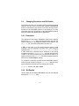
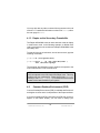
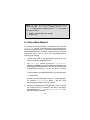
1
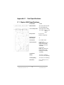
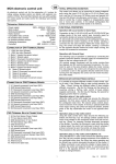
Raptor 4000/4000e Drivers
Installation and Reference
Solaris Manual
Copyright © 2008 Tech Source, Inc.
442 Northlake Blvd.
Altamonte Springs, FL 32701
(407) 262-7100
Publication: 65-0270-01
Rev. B March 25, 2008
Addendum Information
Date Released
March 25, 2008
Changes made to:
REVISION
NUMBER
CHANGES
DATE
A
Initial Release
9-12-07
B
Added support for dual head
3-25-08
The Tech Source logo and Tech Source Raptor are trademarks of
Tech Source, Inc.
Sun, Sun Microsystems, Sun Ultra, Sun Enterprise, Sun Blade,
and Solaris are trademarks or registered trademarks of Sun
Microsystems, Inc.
All other products or services mentioned in this document are
identified by the trademarks or service marks of their respective
companies or organizations. Tech Source, Inc. disclaims any
responsibility for any references to those trademarks herein.
All rights reserved. No part of this work may be reproduced in any
form or by any means without prior written permission of the
copyright owner.
RESTRICTED RIGHTS LEGEND: Use, duplication, or disclosure
by the U.S. Government is subject to restrictions of FAR 52.22714(g)(2)(6/87) and FAR 52.227-19 (6/87); or DFAR 252.2277015(b)(6/95) and DFAR 227.7202-3(a).
ii
The product described in this manual may be protected by one or
more U.S. patents, foreign patents, and/or pending patent
applications.
PREFACE
This publication documents the Tech Source, Inc. Raptor
4000/4000e series cards. This manual is intended for users who
incorporate the Tech Source, Inc. Raptor Cards into Sun PCI and
PCI Express systems.
This also serves as a guide to configuring and using X Windows
software. All systems vary to a degree. Knowledge of the features
of your system is helpful during the installation process.
Warranty
The Raptor cards are warranted for two (2) years from date of
shipment. During the warranty period, Tech Source, Inc. will, at its
discretion, repair or replace a defective component at its expense.
Freight charges associated with the repair or replacement of
components under warranty are to be shared by Tech Source, Inc.
and the customer. All customers, domestic and international, shall
bear the freight charges for the product return. Tech Source, Inc.
shall bear the outbound freight charges up to $20.00 (USD) per
returned product, whether domestic or international.
Any
additional freight charge shall be the responsibility of the customer.
We suggest that you contact your dealer first with any questions
you may have about the product. Unlimited technical support (via
telephone/facsimile/email) is provided for one (1) year from date of
shipment. The installation of any Tech Source, Inc.
hardware/software product is the sole responsibility of the
customer.
Tech Source, Inc. offers a continuing hardware/software support
program that provides telephone consultation and any required
hardware repair after the expiration of the warranty period. This
is a billable annual maintenance contract. Contact Tech
Source, Inc. for the available maintenance plans.
Customers will be charged an hourly rate plus materials
($350.00 USD minimum) for repairs and/or maintenance
performed by Tech Source, Inc. that are not covered by a Tech
Source, Inc. warranty or maintenance contract.
DOCUMENTATION IS PROVIDED “AS IS” AND ALL
EXPRESSED OR IMPLIED CONDITIONS, REPRESENTATIONS
AND WARRANTIES, INCLUDING ANY IMPLIED WARRANTY OF
MERCHANTABILITY, FITNESS FOR A PARTICULAR PURPOSE
OR NON-INFRINGEMENT, ARE DISCLAIMED, EXCEPT TO THE
EXTENT THAT SUCH DISCLAIMERS ARE HELD TO BE
LEGALLY INVALID.
ii
TABLE OF CONTENTS
1 Introduction
1.1 Overview
1.2 Conventions
1
1
2
2 Hardware Installation
2.1 Hardware Configurations Supported
2.2 Installation Instructions
3
3
3
3 Software Installation
3.1 Overview
3.2 Requirements
3.3 Installing Raptor 4000/4000e Card Driver Software
3.4 Changing Resolution and Bit-Depths
3.4.1 Resolution
3.5 atcconfig Utility
3.5.1 Interactive Configuration
3.6 Setting Raptor 4000/4000e as the Console (Optional)
5
5
5
6
8
8
9
9
11
4 Starting X
4.1 Overview
4.1.1 Starting the X server
4.1.2 xinit
4.1.3 Raptor as the Secondary Framebuffer
4.2 Common Desktop Environment (CDE)
4.3 Setting Bit-Depth on 4000/4000e Cards
4.4 MOX Modes
13
13
13
14
15
15
16
16
5 Uninstalling Software
5.1 Uninstalling Raptor Software
17
17
6
19
Technical Assistance
Appendix A: Console Resolution
21
TABLE OF CONTENTS (Cont'd)
Appendix B: Using Nvedit
B.1 NVRAM Edit Commands
29
29
Appendix C: Card Specifications
C.1 Raptor 4000 Specifications
31
31
ii
1
Introduction
1.1
Overview
Thank you for purchasing a Tech Source, Inc. Raptor graphics
card for use with your Sun PCI/PCI Express desktop/server. This
manual describes the installation and configuration of the Raptor
graphics card and the accompanying software. All systems vary
somewhat, therefore some knowledge of the features of your
system and a basic understanding of UNIX shell commands are
helpful during the software installation process.
From this point forward, Tech Source, Inc. will be referred to as
Tech Source or TSI.
The software runs on Sun PCI desktops/servers and supports the
Raptor 4000/4000e graphics cards. The software is provided on a
CD-ROM and consists of:
• Raptor device drivers for Solaris
• Raptor loadable module (DDX) for X Windows
• MOX extension loadable module and libraries
The following products are supported:
Raptor 4000
Supports 2048x2048 resolutions (digital and
analog) on a PCI bus.
Raptor 4000/e Supports 2048x2048 resolutions (digital and
analog) on a PCI Express bus.
The software supports Solaris 9 and 10. Please contact Tech
Source at: [email protected] if you need support for a
different version of Solaris OS.
©2008 Tech Source Inc.
1
Part #65-270-01
1.2
Conventions
This manual will follow certain conventions throughout.
Whenever a variable name, command name, directory, or filename
is used in a paragraph it will appear in a mono-spaced font.
At times the reader will be instructed to enter commands at a
prompt. In this case a transcript of a sample session will be
provided where a prompt will be followed by the commands the
reader is to enter. The entire transcript will be in a mono-spaced
font with the prompt in a normal weight and the user's entries in
bold.
The prompt used in a transcript varies depending on the
circumstances. The following are some common prompts and
when they are used:
prompt#
prompt%
ok
used when the user is required to have root
privileges
used when the user is not required to have root
privileges
prompt displayed when the user is in Boot PROM
mode
2
2
Hardware Installation
2.1
Hardware Configurations Supported
The Raptor cards have been tested on and currently support the
following Sun Microsystems workstations:
• Ultra 25
• Ultra 45
NOTE: If your Sun hardware (workstation) is not listed here, please
contact Tech Source for compatibility verification.
2.2
Installation Instructions
Installing a Raptor card is simple and consists of a few easy steps.
NOTE: Remember which cables go to which connectors. You
may want to label the cables and connectors before
disconnecting them.
Step 1: Shut down the system and turn the power OFF. Remove
the system’s cover along with any cables that prevent you
from doing so. Find an available PCI or PCI Express slot,
and remove the bracket and screw. Ground yourself by
touching the metal part of the case.
Step 2: Install the Raptor card firmly into the PCI or PCI Express
slot. Take care to press it evenly and snugly into the slot.
Once you are certain the card is installed properly in the
slot, secure it with the bracket screw.
Step 3: Secure the system cover and reattach any previously
removed cables, and connect the video cable to the
monitor.
©2008 Tech Source Inc.
3
Part #65-270-01
NOTE: Installation of Raptor4000/4000e driver software is
discussed in Section 3.3
NOTE: If the system is currently using a secondary TSI graphics
device, refer to Appendix A for configuring one of the cards as the
console. The console device is the screen on which the boot up
messages will appear. The monitor must be connected to the
console device before you proceed to one of the following software
installation chapters.
The Raptor card is now installed and the system is ready for
software installation. Refer to Chapter 3 for instructions on
installing the software.
4
3 Software Installation
3.1
Overview
This Chapter describes how to install and configure the Raptor
4000/4000/4000e cards. The software called “Raptor 4000/4000e
Drivers (Solaris)” currently supports the following cards:
•
•
Raptor 4000 (PCI card)
Raptor 4000e (PCI Express card)
NOTE: This software must be installed on your system prior to
running X Windows on these cards.
The software for the Raptor 4000/4000e cards is provided on a
CD-ROM or is available by FTP and is composed of the following
packages:
•
•
•
TSIafp
TSIafpw
TSImox
Device drivers for the Raptor 4000 cards.
DDX for the Raptor 4000 cards.
Device driver package for MOX capability.
NOTE: The current version of this software supports only the high
resolution head, which is the head closest to the PCI/PCI Express
bus.
3.2
Requirements
The following are prerequisites for installing the Raptor
4000/4000e drivers for Solaris:
©2008 Tech Source Inc.
5
Part #65-270-01
•
•
•
3.3
The system is running Solaris 9 or higher.
At least 2MB of disk space is available in /usr and /.
One or more of the cards listed in Section 4.1 are presently
installed in the system.
Installing Raptor 4000/4000e Card Driver
Software
The following are step-by-step instructions for installing the “Raptor
4000/4000e Drivers (Solaris)” software from a CD-ROM.
1.
Install a Raptor card in the computer as described in
Chapter 2.
2.
Boot the computer with the -r (reconfiguration) option by
performing the following steps:
•
•
•
Power ON the computer.
Wait until you see boot messages displaying on
the screen, then press and hold the Stop (L1)
key, and then press the A key.
At the ok prompt, type boot –r.
3.
After the system comes up, log in as root.
4.
Insert the CD-ROM labeled “Raptor 4000/4000e Drivers
(Solaris)” into the drive.
5.
If /cdrom/cdrom0 exists, the CD-ROM was
automatically mounted. Change directories to the CDROM by typing the following:
prompt# cd /cdrom/cdrom0/
If /cdrom/cdrom0 does not exist, mount the CD-ROM by
typing the following:
prompt#
mount -F hsfs -O -o
/dev/dsk/c0t6d0s0 /cdrom
6
ro
\
prompt# cd /cdrom/
6.
To install the software, type:
prompt# ./install_all
This script will ask you a number of yes-or-no questions
(generated by Sun's pkgadd installation program).
Answer these questions appropriately.
7.
To install the MOX module and libraries type:
prompt# cd /cdrom/cdrom0/mox
or
prompt# cd /cdrom/mox
[if the CD-ROM was mounted as outlined in Step 5 above]
prompt# pkgadd –d . TSImox
Note: You must install the MOX package in order to use the MOX
extension.
8.
Reboot the system to complete the installation.
One new device name is created in the /dev/fbs
directory for each head on a Raptor 4000/4000e card. It is
denoted by rapafp# for each Raptor 4000/4000e (where
# represents a minor number assigned by the operating
system). For example, /dev/fbs/rapafp0 is the first
head seen by the system, /dev/fbs/rapafp1 will be
the second head seen by the system.
©2008 Tech Source Inc.
7
Part #65-270-01
3.4
Changing Resolution and Bit-Depths
The default resolution can be determined using the Auto-Detect
feature if you are using a monitor that supports DDC2B/EDID
protocol. Connection to the monitor must occur during the boot
process for the DDC/EDID protocol to be effective. For more
information about the functionality of the DDC2B/EDID protocol
with your Raptor card, please refer to Appendix A.
3.4.1 Resolution
The resolution of the Raptor 4000/4000e card can be changed
through the atcconfig utility. By using this utility, the user can
select a resolution to be displayed, which will be written in the
OWconfig file. This utility is described in Section 3.5.
If DDC is not used, or if the monitor doesn’t report a valid
resolution, then the software will check for a valid resolution
specified in the /usr/openwin/server/etc/OWconfig file. If
a valid resolution is specified and a reference for the timing
numbers occurs in the rapafpresinfo file, then that resolution
is used. If the timing numbers are not specified or there is no
specific resolution in the OWconfig file, then the default resolution
will be set to 2048x2048@60, analog.
To override the resolution specified by the DDC/EDID protocol,
select the new resolution using the atcconfig utility and then
type the following command prior to starting the X server:
prompt#
3.4.2
setenv NO_DDC_CHECK
Bit Depths
The bit depth of the Raptor 4000/4000e card can be changed
through the atcconfig utility.
8
The following bit-depths are supported:
8
8+24
24
8+8
mox24
mox32
3.5
8-bit Pseudo Color
Simultaneous 8-bit PsuedoColor and 24-bit
True Color
24-bit True Color
Two 8-bit Normal 13-bit Group 5-bit Absolute
MOX, 8-bit Normal, 21-bit Group, 13-bit
Absolute
MOX, 8-bit Normal, 24-bit Group, 21-bit
Absolute
atcconfig Utility
After installation you can configure the X Window screen
resolution, bit-depth, and refresh rate for your monitor to be
different from the default settings. The atcconfig utility can be
used any time after installation to change these settings.
The next section describes how to use atcconfig to configure
the Raptor card.
3.5.1 Interactive Configuration
The atcconfig utility has an interactive menu-style interface
(See Figure 3.1). To use this program to configure your Raptor
card, type:
prompt# atcconfig
NOTE: If X Windows is running on the Raptor card(s) to be
configured, please exit out of it before running atcconfig. Failure to
do so could result in a corrupted screen for the remainder of the X
Window session.
The Raptor device(s) will be listed in the left column of the
configuration screen displayed by atcconfig. (See Figure 3.1).
©2008 Tech Source Inc.
9
Part #65-270-01
Figure 3.1 - atcconfig
A description of the commands in the utility is as follows:
Up/Down Arrow
selects the desired graphics device to
modify
Left/Right Arrow
Space Bar
selects the parameter to modify (e.g.
resolution, bit-depth, or sync)
modifies the parameter for the selected graphics
device (will bring up a menu
when applicable)
‘t’
puts a test pattern on the entire display (hit any key to
return to the main screen)
‘s’
saves current settings and exits
‘h’
help
‘q’
exits the program without saving
any changes.
10
3.6
Setting Raptor 4000/4000e as the Console
(Optional)
Refer to Appendix A for instructions on how to configure the
Raptor 4000/4000e card as the console framebuffer.
©2008 Tech Source Inc.
11
Part #65-270-01
This page intentionally left blank.
12
4
Starting X
4.1
Overview
This section describes how to start up X Windows on the Raptor
4000/4000e cards. The examples in this chapter use rapafp0 as
the device name.
Note: The device number corresponding to rapafp# of your card
is assigned by the operating system and could vary for each head.
The following table lists the different Raptor cards and their device
name locations. The device name will have the card’s minor
number appended to it. For example, the first instance of a Raptor
4000/4000e card will have a device name and number of
rapafp0 for the first head and rapafp1 for the second head.
The second instance will have a device name and number of
rapafp2 for the first head and rapafp3 for the other head.
Raptor Card
4000 (First Head)
4000 (Second Head)
4000e (First Head)
4000e (Second Head)
Device Name
/dev/fbs/rapafp0
/dev/fbs/rapafp1
/dev/fbs/rapafp2
/dev/fbs/rapafp3
4.1.1 Starting the X server
Determine the device for your card(s) by running the command,
dmesg | grep rapafp. Use the device name as the option to
the following commands. For the examples below, we assume that
the first head of your device is assigned as /dev/fbs/rapafp0
and the second head as /dev/fbs/rapafp1.
To start the Xserver type:
©2008 Tech Source Inc.
13
Part #65-270-01
prompt#
/usr/openwin/bin/X –dev /dev/fbs/rapafp0
This will start the Xserver only on the first head. If you want to start
the Xserver in multiscreen configuration on both heads, both
device names should be specified on the command line.
For example:
prompt# /usr/openwin/bin/X –dev /dev/fbs/rapafp0 \
–dev /dev/fbs/rapafp1
4.1.2 xinit
The xinit program can be directly used to start the X Window
System server. The xinit format is as follows:
xinit [[client] options] [ -- [server]
[display]
options ]
If no specific client program is given on the command line, xinit
will look for a file in the user's home directory called .xinitrc to
run as a shell script to start up client programs. If no such file
exists, xinit will use the following as a default:
xterm -geometry +1+1 -n login \
-display :0
If no specific server program is given on the command line, xinit
will look for a file in the user's home directory called
.xserverrc to run as a shell script to start up the server. If no
such file exists, xinit will use the following as a default:
X :0
Note that the following example assumes that a program named X
is in the current search path. The xinit script is located in the
/usr/openwin/bin directory.
To startup the server using xinit, type:
prompt% xinit -- /usr/openwin/bin/X -dev \
/dev/fbs/rapafp0
14
You may also add any other command line arguments to the end
of the line. For additional information on the use of xinit, refer to
the man page for xinit.
4.1.3 Raptor as the Secondary Framebuffer
The Raptor 4000/4000e card can work with other cards to display
in multi-screen mode. In the following example, an Nvidia video
card is assumed to be the console and a Raptor 4000/4000e is the
secondary card.
To start the X server on both cards, in multi-screen mode, type the
following commands:
prompt# cd /usr/openwin/bin/
prompt# xinit -- ./X -dev /dev/fbs/nfb0 \
-dev /dev/fbs/rapafp0
The assigned OpenWindows screen numbers correspond to the
order of the devices on the command line.
NOTE: In the above example, the rapafp device number is 0
and it corresponds to the first head of the Raptor card. This may
be different in your configuration. Please check in the /dev/fbs
directory or run dmesg | grep afp to obtain the correct device
number for the card installed on your system.
4.2
Common Desktop Environment (CDE)
Common Desktop Environment (CDE) is available with Solaris 2.5
and higher versions and it is independent of the Raptor software.
If you have installed CDE and would like the CDE login screen to
appear on the Raptor display, you will need to change your
©2008 Tech Source Inc.
15
Part #65-270-01
/usr/dt/config/Xservers file to include the following line:
:0 Local local-uid@console root \
/usr/openwin/bin/X :0 -dev /dev/fbs/rapafp0
You may add any other command line arguments to the end of the
line. In addition, since the graphics devices are dynamically
allocated during each reconfiguration boot, you should check your
/dev/fbs directory for the name of your Raptor device (e.g.
rapafp0 or rapafp1, etc.) or run dmesg |grep rapafp and
then modify the Xservers file accordingly.
When dtlogin is started, a login screen will appear on the Raptor
display. The user may log on to this display using the console
keyboard and mouse.
4.3
Setting Bit-Depth on 4000/4000e Cards
Raptor 4000/4000e cards support 8-bit, 24-bit, 8+24 bit, 8+8,
mox24 and mox32 modes. By default X Windows comes up in 24bit mode on these cards. Changes to the desired bit-depth can be
made by using the atcconfig utility (see Section 3.5).
4.4
MOX Modes
The following MOX modes apply to the Raptor 4000/4000e cards:
Mox16
mox24
mox32
MOX, 8-bit Normal, 13-bit Group, 5-bit Absolute
MOX, 8-bit Normal, 21-bit Group, 13-bit Absolute
MOX, 8-bit Normal, 32-bit Group, 24-bit Absolute
NOTE: Details of the MOX extension to X Server are in a
separate technical white paper. This may be obtained from Tech
Source.
16
5
Uninstalling Software
5.1
Uninstalling Raptor Software
To remove the Raptor 4000/4000e software packages type:
prompt# pkgrm TSIafp TSIafpw
To uninstall the Mox package, type:
prompt# pkgrm TSImox
WARNING: This uninstall procedure is not for use with older
versions of the Raptor software. It is important to use the
procedure, which was provided with the previous release to
uninstall a previous release.
To verify which Raptor packages are installed on your system, type
the following command:
prompt# pkginfo | grep TSI
This will list the packages from Tech Source that are installed on
your system.
©2008 Tech Source Inc.
17
Part #65-270-01
This page intentionally left blank.
18
6
Technical Assistance
6.1
Who to Call for Help
If you need help, please call our Technical Support Team at (800)
330-8301, or directly at (407) 262-7100 between the hours of
9:30am - 5:30pm EST Monday through Friday.
Please have the software part number, version, and serial number
for your Raptor card(s) available when contacting Tech Source in
order to expedite support. Please make a note of this information
in the area below:
DETAILS OF YOUR CARD(S):
P/N:
_________________________________
Model Name:
___________________________
Serial Number(s):
____________________
NOTE: Technical Assistance will be available only for products
under standard or extended warranty.
6.2
Email Address
Our email address is: [email protected].
International customers should use email or our fax line at (407)
339-2554.
6.3
Website
Detailed product information and Frequently Asked Questions
(FAQs), are available on our website located at:
http://www.techsource.com
©2008 Tech Source Inc.
19
Part #65-270-01
This page intentionally left blank.
20
Appendix A: Console Resolution
A.1 Overview
The Raptor 4000 series cards can be configured to be the console
in a typical SPARC desktop/server. The card has a default
console resolution and default depth as shown in the following
table:
Board
4000
4000e
Resolution
Auto Detect
Auto Detect
Refresh
-
Bits/Pixels
8
8
Sync
Separate/composite
Separate/composite
It is possible to change the default resolution on a Raptor
4000/4000e card. The procedures described in this appendix are:
•
•
•
•
EDID Auto-Detect feature
Output Device Method
Video-Mode Method
Video-Timing Method
This appendix includes a troubleshooting section describing
possible problems and answers associated with changing the
console resolution.
A.1.1 Reason for Changing the Console
Resolution
Normally the default console resolution is sufficient for most users.
An example of when you might be required to change the default
resolution is described below:
©2008 Tech Source Inc.
21
Part #65-270-01
•
If the monitor does not "sync up" at the default console
resolution, it may be necessary to choose a different console
resolution.
A.1.2 EDID Auto-Detect Feature
If you are using a monitor with DDC2B/EDID protocol the default
resolution will be determined using the Auto-Detect feature.
With this protocol, the Raptor 4000/4000e card first checks the
Detailed Timing and Established Timing Identifiers (taking the first
one supported) and then tries to match the Standard Timings.
NOTE: The monitor must be turned ON prior to booting the
system in order for a Raptor 4000/4000e series card to
communicate with it. Some adapters and cables may block this
signal.
If the Auto-Detect feature fails the card will default to
2048x2048@60,analog.
Other methods described in this appendix will override any
information obtained via EDID.
A.2 Output-Device Method
For systems with multiple displays, the output-device variable
provides a method to specify which should be used as the console.
When using a Sparc Ultra 25 or 45, please be aware that there is a
limitation in the number of characters you can assign to the
output-device variable. To avert this limitation, you will need to
use the devalias command to set your Raptor 4000/4000e card
as the console device.
The following steps will set a Raptor 4000/4000e card to display
console video by using the output-device variable. Be sure to
make a note of your configuration prior to changing your settings.
22
1.
Connect your cable to the appropriate connector on your
monitor and Raptor 4000/4000e card.
2.
At the prompt type:
ok show-displays
This command will list the installed graphics devices and a
prompt to enter a selection.
3.
Type the letter that corresponds to the Raptor card that you
want to use as the console device. Raptor cards can be
identified by looking for the string TSI in the list of device
names.
For example:
/pci@1e,600000/pci@0/pci@3/pci@0/TSI,rapafp@0
4.
At the ok prompt, type :
ok nvalias <alias name> <Control-Y>
This command will set the specified variable to the path of
the Raptor card. When you type <Control-Y>, the string of
the display that was selected in step 3 will be inserted in the
command line.
5.
The next step is to set the specified variable to the outputdevice. The command to do so is as follows:
At the ok prompt, type :
ok setenv output-device <alias name>
6.
Save your settings and reset the system by typing:
At the ok prompt, type :
ok reset-all
7.
Once the system is reset, all console messages will be
directed to the Raptor card.
©2008 Tech Source Inc.
23
Part #65-270-01
NOTE: To restore the default graphics device as the console
when using the output-device setting, set the outputdevice variable back to its default value of screen by typing the
following command:
ok setenv output-device screen
ok reset-all
A.3 Video-Mode Method
For systems with multiple displays, configurations made with the
video-mode method provide a process to specify which device
should be used as the console. The following steps will configure a
Raptor 4000/4000e card to display console video by using this
method. Be sure to make a note of your configuration prior to
changing your settings.
1. Connect your cable to the appropriate connector on your
monitor and Raptor 4000/4000e card.
2. The video-mode method requires the output-device
variable in NVRAM to be configured with the actual path of the
desired Raptor 4000/4000e card. The path can be determined
by searching for the string TSI in the / tree at the ok prompt.
To find the path to the 4000/4000e device, type the following:
ok show-devs
At least one entry containing the string TSI will be displayed.
For example, TSI,rapafp@#, where # will be a digit
representing your Raptor’s PCI slot number.
2. Use the entry displayed for the Raptor card to set your card as
the console device. For example, if the path to the Raptor
4000/4000e device TSI,rapafp@# is /pci@1f,4000, then
type the following command:
24
ok nvedit
0: devalias screen1 \
/pci@1e,600000/pci@0/pci@3/pci@0/TSI,rapafp@0
NOTE: Replace # with the digit representing your Raptor’s PCI
slot number.
3.
Type <Control-C> to exit the nvedit mode.
4.
To store your new settings type:
ok
nvstore
5. The variable use-nvramrc? must also be set to true in
order for the configuration in nvram to take effect.
To set this variable to true type:
ok
6.
setenv use-nvramrc? true
Save your settings and reset the system by typing:
At the ok prompt, type :
ok reset-all
8.
Once the system is reset, all console messages will be
directed to the Raptor 4000/4000e card.
NOTE: To restore the default graphics device as the console
when using the video-mode method, set the use-nvramrc?
variable to false as given below:
ok setenv use-nvramrc? false
ok reset-all
©2008 Tech Source Inc.
25
Part #65-270-01
A.4 Video-Timing Method
If all of the previously described methods fail for your configuration,
it is possible to specify the exact timing numbers for a particular
resolution. The last method for setting the console resolution also
uses nvedit. This method is more involved and requires
knowledge of all timing parameters for the desired resolution, and
is only meant for monitors whose resolutions are not available in
the video-mode method. Please refer to Appendix C for detailed
instructions on using nvedit.
NOTE: The video-timing method should be used only if the
previous methods have been unsuccessful.
26
A.5 Priority Scheme for the Console
Problem
Used the
method
described in the
Appendix to
configure the
console
resolution, but
the card still
defaults to
something other
than the
resolution
specified.
Solution
A priority scheme is used to determine the boot
console resolution. The Raptor 4000/4000e
firmware checks the various methods in the
order of priority discussed below. If it finds the
resolution from the current method, it uses it;
otherwise, it goes down the priority list to find
the resolution information. Finally, if there is no
resolution information, it uses the default
resolution. The resolution-setting methods are
enumerated in order of decreasing priority:
1. output-device method (Section A.2)
2. video-timing method (Section A.4)
3. video-mode method (Section A.3)
4. DDC2B/EDID (Section A.1.2)
5. Default resolution for the card
©2008 Tech Source Inc.
27
Part #65-270-01
This page intentionally left blank.
28
Appendix B:
B.1
Using Nvedit
NVRAM Edit Commands
This section discusses the use of NVRAM. The NVRAM is used
for setting resolution in the Video-Mode and Video-Timing
methods. To edit the NVRAM, type nvedit at the ok prompt.
There are several commands that you must use to edit the
variables in NVRAM:
<Backspace>
<Ctrl-l>
<Ctrl-p>
<Ctrl-n>
<Ctrl-b>
<Ctrl-f>
<Ctrl-u>
<Ctrl-k>
<Ctrl-u><Ctrl-k>
<Ctrl-c>
deletes the character preceding the cursor
lists NVRAM current values
moves to the previous line
moves to the next line
moves to the previous character
moves to the next character
deletes to the beginning of the line
joins the current and next line
deletes the current line
exits the NVRAM editor (back to the ok
prompt)
The changes will only take effect if they are stored using the
nvstore command entered at the ok prompt. Once the changes
are stored, the NVRAM must be enabled before the system will
execute it. This is done by setting the environment variable usenvramrc? to true. Type reset to reboot the system and make
the changes effective.
©2008 Tech Source Inc.
29
Part #65-270-01
This page intentionally left blank.
30
Appendix C: Card Specifications
C.1 Raptor 4000 Specifications
Frame Buffer:
256 MB
MOX Hardware:
Tech Source MOX 32 ASIC;
24 Layer Management
Color Lookup Table:
2048 entries from a palette
of 16 million colors + 2 AUX
256entry
maps
Bits per Pixel:
8, 16, 24 or 32
(software configurable)
Dynamic Color
Plane Groups:
32
I/O Interface:
PCI, 66 MHz, 64-bit
Video Connector:
DVI-Dual Link
Digital, up to 2048x2048
High Resolution Head
(Analog up to 360 MHz,
50Ω RGB)
DVI-Dual Link
Digital, up to 1920x1200
High Resolution Head
(Analog up to 330 MHz,
75Ω RGB)
Temperature
Rating:
©2008 Tech Source Inc.
0
0
10 to 50 C (operating)
0
0
-10 to 70 C (non-operating)
Humidity Rating:
10 to 90% (non-condensing)
Dimensions:
6.6 in. (168mm) x 4.37 in.
(111mm)
31
Part #65-270-01
C.2
Raptor 4000e Specifications
Frame Buffer:
256 MB
MOX Hardware:
Tech Source MOX 32 ASIC;
24 Layer Management
Color Lookup Table:
2048 entries from a palette
of 16 million colors + 2 AUX
256entry
maps
Bits per Pixel:
8, 16, 24 or 32
(software configurable)
Dynamic Color
Plane Groups:
32
I/O Interface:
PCI, 66 MHz, 64-bit
Video Connector:
DVI-Dual Link
Digital, up to 2048x2048
High Resolution Head
(Analog up to 360 MHz,
50Ω RGB)
DVI-Dual Link
Digital, up to 1920x1200
High Resolution Head
(Analog up to 330 MHz,
75Ω RGB)
Temperature
Rating:
32
0
0
10 to 50 C (operating)
0
0
-10 to 70 C (non-operating)
Humidity Rating:
10 to 90% (non-condensing)
Dimensions:
6.6 in. (168mm) x 4.37 in.
Tech Source
442 Northlake Blvd.
Altamonte Springs, Florida 32701 U.S.A.
www.techsource.com
Phone: (407) 262 7100
Email: [email protected]