1
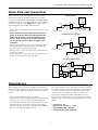
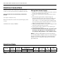
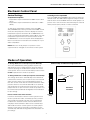
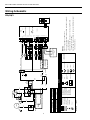
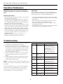
Envision Pool Heater Installation Manual
Pool Heater
Installation Information
Water Piping Connections
Chemical Use
Electrical
Startup Procedures
Preventive Maintenance
Troubleshooting
IM1009PN 07/10
ENVISION POOL HEATER INSTALLATION MANUAL
Table of Contents
General Introduction . . . . . . . . . . . . . . . . . . . . . . . . . . . . . . . . . . . . . . . . . . . . . . . . . . . . . . . . . . . 4
General Performance . . . . . . . . . . . . . . . . . . . . . . . . . . . . . . . . . . . . . . . . . . . . . . . . . . . . . . . . . . . 4
Installation . . . . . . . . . . . . . . . . . . . . . . . . . . . . . . . . . . . . . . . . . . . . . . . . . . . . . . . . . . . . . . . . . . . . 4
Water Flow and Connections . . . . . . . . . . . . . . . . . . . . . . . . . . . . . . . . . . . . . . . . . . . . . . . . . . . . 5
Chemical Use . . . . . . . . . . . . . . . . . . . . . . . . . . . . . . . . . . . . . . . . . . . . . . . . . . . . . . . . . . . . . . . . . . 5
Electrical Connections . . . . . . . . . . . . . . . . . . . . . . . . . . . . . . . . . . . . . . . . . . . . . . . . . . . . . . . . . . 6
Electrical Data . . . . . . . . . . . . . . . . . . . . . . . . . . . . . . . . . . . . . . . . . . . . . . . . . . . . . . . . . . . . . . . . . 6
Electronic Control Panel . . . . . . . . . . . . . . . . . . . . . . . . . . . . . . . . . . . . . . . . . . . . . . . . . . . . . . . . 7
Modes of Operation . . . . . . . . . . . . . . . . . . . . . . . . . . . . . . . . . . . . . . . . . . . . . . . . . . . . . . . . . . . . 7
Wiring Schematic . . . . . . . . . . . . . . . . . . . . . . . . . . . . . . . . . . . . . . . . . . . . . . . . . . . . . . . . . . . . . . 8
Startup Procedures . . . . . . . . . . . . . . . . . . . . . . . . . . . . . . . . . . . . . . . . . . . . . . . . . . . . . . . . . . . . 9
Preventive Maintenance . . . . . . . . . . . . . . . . . . . . . . . . . . . . . . . . . . . . . . . . . . . . . . . . . . . . . . . . 10
Troubleshooting . . . . . . . . . . . . . . . . . . . . . . . . . . . . . . . . . . . . . . . . . . . . . . . . . . . . . . . . . . . . . . 10
ENVISION POOL HEATER INSTALLATION MANUAL
Pool Heater
Safety Considerations
General Information
• Qualified personnel should perform installation,
maintenance, and service.
• Make sure all field wiring conforms to the heater
specifications and all national and local codes.
• Disconnect all power sources before performing any
maintenance or service to the heater.
You now own one of the most efficient and versatile pool
heaters on the market today. Your heat pump pool heater
will typically operate with a Coefficient of Performance
(COP) of 3.0 to over 5.0 depending on the operating
conditions. This means that your heater can supply 3-5
times as much heat to the pool as it consumes in electrical
power. In addition, it will still warm your pool even as
outdoor temperatures drop into the 40s.
Inspection
Immediately upon receipt, inspect cartons and their
contents for damage due to transit. Damage, if found,
should be noted on delivery papers and a claim filed with
the carrier. Also, check unit data plate to make sure you
have the proper model, before installing.
The information in this manual was prepared to assist in
the proper installation, operation, maintenance, and service
of your new heat pump pool heater. Please read the entire
manual and follow all instructions. Improper installation
and use can result in damage to the heater, unsatisfactory
operation, and may void the warranty. Retain this manual
for quick reference.
General Performance
Installation
The AC-1750B can produce 85,000 – 165,000 Btu/hr for
your pool heating needs depending upon the operating
conditions. At AHRI conditions of 80°F entering water
temperature (EWT) and 80/71°F dry bulb/wet bulb
entering air temperature (EAT) a COP of over 5 is possible
with an output of over 120,000 Btu/hr.
When selecting a location consider the following:
• Heater must be located outdoors (NOTE: The pool heater
will operate with a noise level of around 65 dbA.)
• Minimum of 24 in. of clearance on access/service side of
heater
• Minimum of 18 in. of clearance on all three air intake sides
of heater
• Minimum of 48 in. of clearance for air discharge (top of
unit)
• The heater should sit on a solid level surface sufficient
above grade to prevent water from entering it, and
allowing condensate to drain from base.
• The length of water piping and electric should be kept
to a minimum to avoid capacity loss and decreased
efficiency.
4
ENVISION POOL HEATER INSTALLATION MANUAL
Water Flow and Connections
Typical Installation
Water connections are made at the rear of the heater.
Both water in and out are labeled just above the water
connections. LEFT REAR = WATER OUT and RIGHT REAR
= WATER IN. Two in. unions are supplied and are made to
accept 2 in. rigid PVC pipe. NOTE: Unions can be used for
quick drainage of your heater and winterizing.
Heat Pump
Pool Heater
Filter
Pump
• Heater must be piped downstream from filter in the pool
return line.
• In-line chlorinators must be piped downstream from
heater. A check valve must be installed between the
heater and chlorinator to prevent drain back of the
chlorine when the pump is off. A chemical trap may
also be piped at least 6 in. above the height of the
chlorinator.
• When all the plumbing connections are complete, and
ample drying time is allowed, run the filter pump and
check the entire system for water leaks.
• Make sure filter is clean and there are no obstructions in
the filtering system.
• Proper water flow is essential to the performance of your
heater. The minimum flow rate is 20 gpm.
In
Out
Ball Valve - For Flow Rates
Greater than 70 gpm or
Pumps Larger than 1.5 H.P.
From Main Drain/Skimmer
Return
Installation with In-line Chlorinator
Heat Pump
Pool Heater
Pump
Filter
In
Out
Ball Valves
Chlorine
Gas Trap
From Main Drain/Skimmer
Automatic
Chlorinator
Return
Check Valve
Installation with Pool and Spa
Filter
Pump
3-Way
Valve
Heat Pump
Pool Heater
External
Pressure Switch
Pool
Spa
AutoChlor
Gas
Trap
3-Way
Valve
Chemical Use
Water quality must be checked regularly and maintained
within recommended limits at all times. Failure to maintain
the proper water quality will greatly reduce the life of your
heater.
The heat exchanger in your heat pump contains a titanium
inner tube with a PVC outer shell that will withstand almost
any water chemistry. While the heat exchanger provides
superior protection against poor water chemistry, it is
important to maintain adequate water quality to help
preserve other components in the system such as pumps
and filters. The following water quality guidelines are listed
below.
• Never add chemicals directly into skimmer.
• Automatic chlorinators must be piped downstream from
the heater. A check valve must be installed between
the chlorinator and heater to prevent raw chlorine from
draining back into the heater. A chemical trap may be
piped at least 6 in. above the chlorinator. See Installation
with In-line Chlorinator diagram above.
• pH Level 7.4 – 7.8
• Chlorine Concentration 1 – 5 ppm
• Total Alkalinity 100 – 200 ppm
• Calcium Hardness 100 – 300 ppm
5
ENVISION POOL HEATER INSTALLATION MANUAL
Electrical Connections
Wiring Main Power Supply
Field connections must comply with national and local
codes. The work must be done by a qualified electrician.
1. Remove the screws from the plastic front panel, located
on the control display side of the unit.
2. Remove the screws from the front panel of the control
box.
3. Route weather tight flexible conduit through the
opening at the base of the unit. Connect conduit to the
bottom of the electrical control enclosure to accept
either a 3/4 in. or 1 in. fitting. Mounting conduit directly
to the electrical control enclosure will ensure a moisture
tight seal, extending the life of the heater.
4. Attach grounding conductor to the ground lug provided
inside the electrical control enclosure.
5. Install L1 and L2 input conductors to the input lugs of
the compressor contactor.
6. Connect bond wire (at least #8 solid copper wire) from
bond lug on the right side of coil header plate to the
pool pump bonding terminal or other suitable location.
The pool heater must be permanently grounded and
bonded.
Use copper conductors only.
Disconnect all power sources before performing any work
on unit.
Standard Power Supply: 230/60/1
NOTE: According to NEC 680-22, all metal surrounding a
pool including pumps, handrails, rebar, etc. must be bonded
together to eliminate any difference in potential between
the parts. If a pool is properly installed, it has a bonding
grid established.
Electrical Data
Compressor
Model
Rated
Voltage
Voltage
Min/Max
RLA
LRA
Fan Motor
FLA
Total Unit
FLA
Min
Circ Amp
Max
Fuse/HACR
AC-1750B
230/60/1
207/254
26.9
134.0
2.8
29.7
36.4
60
NOTES: HACR circuit breaker in USA only. All fuses Class RK-5.
6
ENVISION POOL HEATER INSTALLATION MANUAL
Electronic Control Panel
Control Settings
Selecting Pool or Spa Mode
Temperature Setpoint
Press the POOL/SPA/STANDBY button until you reach the
desired mode. The LED indicator light will verify the mode
that has been selected. NOTE: When the mode jumper is in
position 2-3 or 3-4 the mode is determined by the external
water pressure (flow) switch or remote controller.
• Temperature setpoint maximum for POOL mode is 95°F
(35°C).
• Temperature setpoint maximum for SPA mode is 140°F
(40°C).
To change the temperature setpoint, press the POOL/
SPA/STANDBY button until you reach either POOL or SPA
mode, this will prompt the control to display the current
temperature setpoint. Hold either UP or DOWN button to
scroll to your desired temperature setpoint. Once your new
temperature setpoint has been reached, release the UP
or DOWN button. Your new setpoint will be displayed for
fifteen seconds then revert back to the actual pool or spa
water temperature.
NOTE: When the mode jumper is in position 3-4, the
setpoint must be changed on the remote control system.
Modes of Operation
Terminal Strip and Mode Configuration Pins
To Change Between Pool and Spa Setpoints Manually:
This is the default factory setting (jumper on pins 1-2)
and allows the use to change between the pool and spa
setpoints by using the mode button located on the front
control panel. The use of an external water pressure switch
IS NOT required for this mode of operation.
1
2
To Change Between Pool and Spa Setpoints Automatically:
This change can be done automatically as the water flow
is directed to either the pool or spa. The use of an external
water pressure switch in the spa piping IS necessary. A
two-wire control circuit must be connected from the water
pressure switch to the terminals 9 and 10 on the terminal
strip located in the electrical control enclosure. The mode
jumper must be on pins 2-3 for this mode of operation. See
the Terminal Strip and Mode Configuration Pins illustration
for pin settings.
3
Mode
Configuration Pins
Removable
Jumper
4
5
4
3
2
1
6
7
8
9
10
11
12
Terminal
Strip
Remote Thermostats and Controllers:
If a remote thermostat or another control system is to be
used to operate the heater, a normally open dry contact
can be made at terminals 11 and 12 on the terminal strip
located in the electrical control enclosure. Remove the
red jumper from terminals 11 and 12 on the terminal strip
and install the remote control system. The mode jumper
must be on pins 3-4 for this mode of operation. See the
Terminal Strip and Mode Configuration Pins illustration for
pin settings.
7
Electronic
Controller
8
Brown
Cap
Black
Black
Black
PTCR
Note 2
Blue
L2
T2
Orange
Cap
S
Red
R
97P675-01
12/1/09
Wire nut
Screw terminal field connection
Quick connect terminal
Optional block
Field line voltage wiring
Field low voltage wiring
Factory line voltage wiring
Factory low voltage wiring
CC
C
Bl ack
L1
T1
CC - Compressor contactor
DC - Defrost Cycle
WT - Water Temperature
HP - High pressure switch
LP - Low pressure switch
Fan - Fan relay
FS1 - Flow Switch 1
FS2 - Flow Switch 2
RM - Remote Automation
Jumper Setting
1&2
2&3
3&4
Table 1 - Jumper Configurations
Crankcase
Heater
Bl ack
Yellow
Brown
Application
Pool/Spa (1 Valve)
Pool/Spa (2 Valve)
Remote Automation
Note 1
4
RB
2
Gree n
Fan Motor
Compre ssor
P
Black
Com
Blue
230 V
G
Red
208 V
L1
Tr ansformer
Polarized connector
Thermistor
Capacitor
Relay coil
Relay Contacts N.O., N.C.
Switch -High pressure
Black
Red
Black
Black
Bl ue
Blue
Red
Red
TS
12
11
9
10
2
1
8
TS
7
6
5
4
3
Not Used
24
Red
FP
Bl ack
X1
Violet
X3
Gray
X3
X2
Orange
Gray
X2
Violet
Orange
X1
WAT
Yell ow
Ye llow
WAT
FP
Black
PIN 1
LP
LP
HP
Bl ue
Blue
Black
HP
CC
Black
CCG
F2
F1
C
PIN 1
Viol et
P2
P1
Bl k/Wht
Brown
Blue
Black
P3
1
3
See Table 1
2
P5
4
Remote Automation Jumper
Microprocessor Control
TEST
PIN
Interface Panel
NOTES:
1. Use only copper conductors.
2.Connect field wiring in grounded rain-tight conduit,
per rating plate.
3.Connect bond wire to pool steel using #8 solid
copper wire or larger.
4.All wiring must conform to national (NEC) and local
electrical codes.
Field Installed home
automation control. See
Table 1.
FS1
WT
DC
LP
HP
CC
Fan1
1 - Only on 105 models.
2 - Only on 080 models.
Notes:
Field Installed Flow
Switch. See Table 1.
FS2
Switch -Low pressure
T
Bl ack/White
24V
Yell ow
A
PS
Orange
Ground
Field wire lug
Legend
Unit
Po wer Su pply
208-230/60/1
Green
C
D
ENVISION POOL HEATER INSTALLATION MANUAL
Wiring Schematic
230/60/1
1
3
2
ENVISION POOL HEATER INSTALLATION MANUAL
Startup Procedures
Defrost Cycle
Before proceeding with this section make certain all
plumbing connections are airtight and leak-free.
The heat pump pool heater has automatic defrost. When
the outdoor temperature drops below 40°F, frost may
start to form on the evaporator coil. Frost buildup will be
heaviest on humid days when the temperature is between
35 – 40°F. During the defrost cycle, the Defrost LED will be
illuminated to indicate that the unit is defrosting. During
this time the fan is funning and the compressor is inactive.
Flow rates should not exceed 70 gpm maximum. Use of
an external bypass is necessary at 70 gpm and above.
Minimum flow rate is 20 gpm.
• Turn filter pump time clock to the ON position and set
filter pump hours. For initial heating, the pool heater
and filter pump may need to run continuously until your
desired temperature is reached. After initial heating is
achieved, the heater will run only to maintain desired
temperature.
• Turn power supply to heater ON.
• The amber Standby LED will be activated.
• Select POOL or SPA and set your desired water
temperature by scrolling either up or down.
• If your programmed water temperature is above the
actual water temperature, the red HEAT LED will light up
indicating HEAT mode. The can will start, and then the
compressor will start.
Internal Protection Analyzers
The heater is equipped with internal devices to monitor
and protect the integrity of the unit. Should an abnormal
condition occur, these devices will interrupt the operation
of the unit and may display the appropriate code on the
control panel.
Reducing Heat Loss - Pool Cover/Solar Blanket
We highly recommend the use of a pool cover/solar
blanket. Covering your pool is the single most cost effective
means of reducing heat costs from 50 – 70%. Heating
a pool without a cover is like heating a house without a
roof. They also reduce the amount of maintenance costs.
By reducing evaporation, covers reduce the quantity of
chemicals needed. Because evaporation accounts for about
70% of pool heat loss, the beneficial effect of using a pool
cover/solar blanket can be dramatic.
NOTE: Each time the compressor turns off, it is protected
by a 3 – 5 minute anti-short cycling delay.
Initial Heating
Initial heating may require you to run your heater and
filter pump continuously for at least 24 hours, or more,
depending on the following factors:
• Temperature difference between actual water
temperature and desired water temperature
• Size of pool
• Ambient air temperature, the cooler the air temperature,
the longer the heating time
• Heat loss (evaporative, convective, radiative, and
conductive)
• A pool cover/solar blanket may reduce initial heating
time by up to 50%
Wind Speed Reduction
Reducing wind velocity at the water surface reduces
convective and evaporative losses. Fences, trees, hills,
or tall hedges close to the pool perimeter are effective
windbreaks. Locate these obstructions to take maximum
advantage of their effectiveness as windbreaks, without
shading the pool surface from the sun.
9
ENVISION POOL HEATER INSTALLATION MANUAL
Preventive Maintenance
Winterizing
WARNING: Disconnect electrical power to unit before
starting any maintenance to prevent serious injury from
shock.
When the heater is exposed to freezing temperatures, it is
essential that all water within the unit be properly drained.
When water freezes, it expands, damaging piping.
Protecting the Heater
• Turn thermostat settings to OFF. Turn filter pump to OFF.
• Turn power to unit OFF (i.e. pull disconnect or turn circuit
breaker OFF).
• Disconnect water inlet and outlet unions at the back of
the unit, be careful no to lose rubber o-rings.
• Flush the heater piping out with fresh water to remove
any residual chemicals.
• Use low-pressure air or vacuum to remove water that has
accumulated inside the piping of the heater.
• Keep the pool filter system clean and free of restrictions
to ensure proper water flow.
• Check water chemistry regularly. Misuse of chemicals
will cause permanent damage to the heater and other
pool equipment. Manufacturers can void warranties for
damage as a result of poor water quality.
• Free airflow is essential. Keep the evaporator coil clean
and free of weeds, leaves, grass clippings, dirt, and other
debris that will decrease the airflow. Keep fences and
shrubs away from air inlets (sides and back of heater).
• Frequent rinsing of the evaporator with fresh water will
remove buildup from its surface. Always spray the coil
gently with a regular garden hose being careful no to
bend aluminum fins.
• Regular cleaning of the cabinet will improve its
appearance and extend the life of the finish.
Troubleshooting
1.
Check to be sure that the electrical power is ON. Reset
the breakers or replace fuses if necessary.
2. Check to be sure the electronic control panel is set
properly. The unit must be in either the POOL or SPA
mode and the desired temperature must be set above
the actual pool or spa temperature for the heater to
run. If an error code is displayed, reference the table
below to determine the cause.
3. Check to make sure the evaporator coil has enough
clearance and that there are no restrictions to its
airflow.
4. Certain ambient air conditions may cause the heater
to go into defrost mode. The defrost mode will be
indicated by the Defrost LED.
Error Code
Description
Little or no water flow
The pump is not running
The filter is dirty or clogged
Shortage of water to pump, air leak
Undersized pump
Valves not in correct position
Filter in backwash mode
Water pressure switch needs
adjustment or its defective
Internal Flow
Switch Open
Remote Mode
Same as above
FS
HP
High Pressure
Switch Open
Low water flow to heater
Defective high pressure switch
Low Pressure
Switch Open
Evaporator coil is dirty
Fan motor is not running
Low refrigerant pressure
Defective low pressure switch
PO
Water Thermistor
Open
Loose sensor wire
Defective water thermistor
HC
Water Thermistor
Closed
Wire terminals touching
Defective water thermistor
dO
Defrost Sensor
Open
Loose sensor wire
Defective defrost sensor
Dc
Defrost Sensor
Closed
Wire terminals touching
Defective defrost sensor
bO
Control Voltage
Below 18VAC
Low supply voltage to the unit
F1
LP
NOTE: It is normal for water to drip from the drain holes at
the base of the heater. The unit produces condensate when
it operates.
The following table lists error codes as the would appear
on the electronic control display. In the event that an
error does occur, check the possible causes list for the
corresponding error to correct the problem.
10
Possible Causes
Internal Flow
Switch Open
Manufactured by
WaterFurnace International, Inc.
9000 Conservation Way
Fort Wayne, IN 46809
www.waterfurnace.com
IM1009PN
07/10
Product: Type:
Document:
Envision Series
Pool Heater
Installation Manual
©2010 WaterFurnace International, Inc., 9000 Conservation Way, Fort Wayne, IN 46809-9794. WaterFurnace has a policy of continual product research and development and
reserves the right to change design and specifications without notice.