1
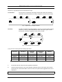
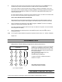
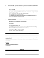
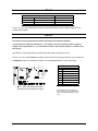
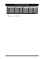
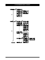
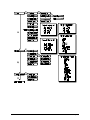
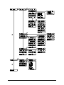
ADVISOR ® CD 3403 Installation Manual Software from version: V6.0 142714999-2 COPYRIGHT SLC BV 1996. All rights reserved. No part of this publication may be reproduced, transmitted, stored in a retrieval system, or transmitted in any form, or by any means - electronic, photocopying, recording, or otherwise - without the prior written permission of SLC BV. DISCLAIMER SLC BV makes no representations or warranties with respect to the contents hereof and specifically disclaim any implied warranties of merchantability or fitness for any particular purpose. Further SLC BV reserve the right to revise this publication and to make changes from time to time in the contents hereof without the obligation of SLC BV to notify any person of any such revision. HOW TO USE THIS MANUAL This manual contains installation details for the CD34. When used in conjunction with the Programming Manual and the User Manual, it provides the installation engineer with basic installation and programming information. Programming The 'Programming Manual' for the CD34 covers all necessary aspects of programming the system. Everybody involved in installing or maintaining this panel should have access to a copy of this manual. The 'Programming Manual’ is available from your ARITECH national office. The ‘Programming Map’ for the various systems can be found at the end of this manual. Installation manual for CD3403 Page 3 CONTENTS INSTALLATION GUIDELINES ......................................................................................................5 Before switching on the power ..................................................................................................... 6 Programming guide ..................................................................................................................... 7 Returning to default settings ........................................................................................................ 7 Leaving programming mode ........................................................................................................ 8 Dialler .......................................................................................................................................... 8 Other manuals ............................................................................................................................. 9 INSTALLATION GUIDE ............................................................................................................10 Wiring diagrams CD3403........................................................................................................... 10 Opening CD3008 / CD3048 keypads ......................................................................................... 11 Opening CD3009 / CD3049 keypads ......................................................................................... 11 CD3008 / CD3009 keypad .........................................................................................................12 CD3048 / CD3049 keypad ......................................................................................................... 12 Keypad back tamper .................................................................................................................. 13 Connection of a detector without memory .................................................................................. 14 Connection of a detector with Latch ........................................................................................... 14 Connection of a key switch ........................................................................................................ 15 Connection of a relay or an LED ................................................................................................ 15 Connection of an AS256 and AS294/394 sounder ..................................................................... 16 Connection of GS600/610/710/711 shock sensor ...................................................................... 17 Zones......................................................................................................................................... 18 Output........................................................................................................................................ 18 TECHNICAL SPECIFICATIONS ..................................................................................................19 PROGRAMMING MAP CD3403 ...............................................................................................20 Page 4 Installation manual for CD3403 INSTALLATION GUIDELINES The CD3403 control panel has been designed, assembled and tested to meet current standards of stability and resistance to electrical interference from the environment. If the following guidelines are followed, the system should give many years of reliable service. 1. Ensure that there is a good earth for the alarm system. A GOOD EARTH IS ESSENTIAL FOR EFFECTIVE RESISTANCE TO ELECTRICAL INTERFERENCE Do not forget to provide a (network) earth for the telephone dialler. 2. Maintain a good separation between low voltage and mains supply cables, and use separate points of entry into the control panel cabinet. 3. Avoid loops of wire inside the control panel and route cables so they do not lay on top or underneath the printed circuit board. The use of cable ties is recommended and improves neatness in the box. 4. Mains switching relays must NOT be fitted inside the control panel cabinet. The switching of these relays may cause electrical interference. 4.1 Use a relay with good insulation between the contacts and the coil. 4.2 Place a suppression diode (e.g. a 1N4001) across the relay coil. 4.3 Relays connected to open collector outputs of the alarm system should be rated at 12 volts DC with a coil impedance greater than 400 Ohms. 5. The remote bus cable is used for communication between the control panel and the keypads/expanders. The greatest care should therefore be taken when installing this cable. NEVER split this cable into separate cables. Do not use cables with wires which are used for TELEPHONE connections or for switching, for example, flashing lights, sirens or relays. 6. Avoid cable ducts and cable ways which contain mains power cables. This is particularly important when such ducts contain cables supplying electric motors, fluorescent lights or 3-phase power. If this is not possible, shielded cable should be used and the cable should be earthed at the control panel end ONLY. Installation manual for CD3403 Page 5 BEFORE SWITCHING ON THE POWER Detectors (or key switches) can be connected in two ways: Conventional: One zone each is required for both tamper and the alarm. Both zones should be closed with an end-loop resistor (4.7 kOhm). Program the ‘zones’ menu as ‘Alarm’ Figure 1. Separate alarm and tamper connection Dual loop: The alarm and tamper are placed together in one zone. The zone has two end-loop resistors (4.7 kOhm) to differentiate between alarm and tamper. Figure 2 shows how they are connected. Program the ‘zones’ menu as ‘Dual’. Figure 2. Joint connection of the alarm & tamper This connection method gives the following input values: The zone is Resistance Panel zone voltages Remote zone voltages Reaction on standby 3k5 - 6k2 2.1 - 2.8 V 4.7 - 6.8 V none triggered 6k6 - 11k7 2.9 - 3.6 V 6.9 - 8.6 V alarm open > 12k7 > 3.7 V > 8.7 V tamper short-circuited < 2k9 < 1.9 V < 4.6 V tamper Table 1. Operation of the inputs 1. Set the DIP switches of all the remote keypads and expanders. 2. Close the tamper switches on the remote keypads, expanders and the control panel. Also close all zones which can cause a direct alarm. If this is not done, the system will be triggered as soon as it is switched on. 3. Remove link JP1 from the PCB so that it returns to default settings. Page 6 Installation manual for the CD3403 4. Supply only mains power to the control panel. The system will power up in the ARMED state. Any zones that may be open will initiate a full alarm condition and the sounders will activate. Do not use a battery to power the system when installing or changing the installation. If there is a short circuit in the 12 volt power supply, the voltage regulators in the supply (together with the fuses) will prevent serious damage to the system The 12 volt power supply will decrease sharply in the event of a short circuit. If a short circuit should occur, remove the 12 volt connections one by one. When the connection with the short circuit is removed the power supply will return to 12 volts. NOTE: ONLY KEYPAD ONE IS OPERATIONAL. Every time power is removed from the system the control panel memorises its status. If power is restored to the panel, the system starts up again in this status (except if JP1 has been removed). 5. Enter ‘0’ followed by the default user code ‘1122’ at keypad 1. 'Disarm?’ is shown on the display. !‘ button. System then disarms after pressing the ‘! If the sirens have been activated, these will now stop. The status of the system or the time and date will now appear in the display. 6. "’ to return to Enter ‘0’ followed by the default engineer’s code ‘1278’ at keypad 1 and press ‘" programming mode. N.B. Do not forget to initialise additional keypads and expanders with the menu 5.2, ‘INSTALL REMOTE’ Replace JP1. PROGRAMMING GUIDE Always enter a ‘0’ before entering an engineer/user code to prevent errors ! ! Under keys 1 to 9 there are 3 letters of the alphabet: press the keys repeatedly to enter first the number, then the lower case letters and then the upper case letters. Keys 9 and 0 have special symbols such as the comma and space. The arrows move the cursor during entry. !’ to accept an entry. Press ‘! Cancel an entry by pressing ‘X’. End To delete a character, overwrite with another character or a space. DISPLAY ABC DEF GHI 1 2 3 JKL MNO PQR 4 5 6 STU VWX YZ 7 8 9 Cursor left # Accept Cursor right 0 " up down X Note: CD30xx stands for the keypads: CD3008, CD3048, CD3009 and CD3049 Figure 3. Keys on a CD30xx RETURNING TO DEFAULT SETTINGS There are two methods of returning the system (not the dialler) to default settings, these are: Installation manual for the CD3403 Page 7 1. 2. By removing the JP1. Subject to the ‘Engineers Lock’ not being programmed, this method will return the panel to default settings without the use of an engineer’s code. Proceed as follows: - Remove both the battery and the mains power. - Remove jumper JP1. - Connect the mains power. Only keypad 1 is operational. The software version is displayed on the other keypads (if present). As the default setting is “armed” any open zones will trigger the system and the sounders will activate. Enter ‘0’ followed by the default code ‘1122’ to disarm the system. Use code ‘1278’ to return to programming mode. If the default codes are invalid, the system has ‘Engineers Lock’ blocking programmed. If the current engineers’ code is known use procedure 2, if not, then replacement of the PCB is the only way to gain access to programming mode. By programming. Use this method if ‘Engineers Lock’ blocking is active and the engineers’ code is known. Proceed as follows: - KEYPAD ONE MUST BE USED FOR THIS PROCEDURE THE SYSTEM MUST BE DISARMED - Go to keypad 1. - Enter the installation engineers’ code. - Press ‘6’, ‘6’ and ‘1’ successively. You are now in the menu ‘Miscellaneous’, ‘Factory Prog. Menu’, ‘Default Settings’. ‘Are you sure?’ flashes in the display. - !’). ‘Wait ...’ appears in the display. Press accept (‘! - The system has now reverted to default settings. LEAVING PROGRAMMING MODE Before leaving programming mode use the ‘Show Open Zones’ facility under the ‘Maintenance’ menu (menu 1.3). If any zones shown are 24Hr zones (e.g. tamper or fire) the alarm will activate on leaving the engineers’ programming mode. If dual loop is programmed, the letter T will appear next to the zone number to indicate the tamper section of the loop is open. Procedure: a. Check for open 24Hr zones (see above). b. Press ‘X’ until ‘Goodbye’ is displayed. !’. c. Press accept ‘! DIALLER Page 8 Installation manual for the CD3403 The use of the RD6203 dialler is recommended. This dialler fits inside the control panel cabinet and is connected to the control panel’s PCB using the cable supplied. The dialler may be programmed via the keypad. A separate manual is available for the dialler. OTHER MANUALS Programming Manual CD3403 A fully documented programming information manual. User manual Details user options. Manager Manual A user manual which examines the options in more depth. Intended for the manager. Programming Manual RD6203 Documented information on programming the RD6203 dialler. Installation manual for the CD3403 Page 9 INSTALLATION GUIDE WIRING DIAGRAMS CD3403 Figure 4. CD3403 PCB Page 10 Installation manual for the CD3403 OPENING CD3008 / CD3048 KEYPADS Figure 5. Opening the CD3008 / CD3048 keypad OPENING CD3009 / CD3049 KEYPADS Lift up Push Remove screw if installed Push clip in with screwdriver and lift up cover Figure 6. Opening the CD3009 / CD3049 keypad Installation manual for the CD3403 Page 11 CD3008 / CD3009 KEYPAD Figure 7. CD3008 / CD3009 keypad CD3048 / CD3049 KEYPAD Figure 8. CD3048 / CD3049 keypad DATABUS PNL 19 20 21 22 REM A B C D Description + 12 Vdc GND data OUT data IN Table 2. Databus connections Page 12 Installation manual for the CD3403 KEYPAD BACK TAMPER • CD30xx base $. • When the keypad lid is not used, remove the hinge-slot blanking pieces from the base %and place them in the hinge-slot openings &. • For back tamper protection fix the screw through the hole into the wall '. Installation manual for the CD3403 Page 13 CONNECTION OF A DETECTOR WITHOUT MEMORY 4k7 1 2 4k7 A A 3 4 S S 6 7 5 Input zone Power supply Figure 9. Dual loop connection of a detector without memory CONNECTION OF A DETECTOR WITH LATCH 4k7 1 2 Power supply 4k7 A A 3 4 5 Input zone S S 6 7 8 M W 9 10 Output “Latch” Output “Walk test” Figure 10. Dual loop connection of a detector with latch Note: Before connecting, the cable between terminal 2 and terminal 10 should be removed! Page 14 Installation manual for the CD3403 CONNECTION OF A KEY SWITCH C NO 4k7 NC To “key” zone Key switch 4k7 C NC Tamper +12V 1K 1K To “Arm/Diarm” output To “System Clear” output Programme outputs for negative applied (-) Figure 11. Connection of a key switch with LED's CONNECTION OF A RELAY OR AN LED +12 Volt NC NO +12 Volt R = 820Ω Output C Output Figure 12. Connection of a relay or an LED on the output The resistor R is necessary to adjust the current. For most LED’s a current of approximately 15 mA is sufficient. The resistance calculation is as follows: R= V I = 13.8V − Vled 13.8V − 2V = = 787Ω 15 mA 15mA When rounded off this is 820 Ohms. Installation manual for the CD3403 Page 15 CONNECTION OF AN AS256 AND AS294/394 SOUNDER Figure 13. Connection of the AS294/394 & internal siren AS256 Programming CD3403 Beacon control Internal siren control 01 Int Sir Sy + 05 Int Sir Sy - External siren control 06 Ext Sir Sy + Table 3. Programming sirens Page 16 Installation manual for the CD3403 CONNECTION OF GS600/610/710/711 SHOCK SENSOR Figure 14. Connecting the GS710/711 with separate alarm & tamper loops Figure 15. Connecting the GS710/711 with combined alarm & tamper loops Installation manual for the CD3403 Page 17 ZONES Zone Types No. 1 2 to 10 Zone Options Standard Exit/Entry 1 Alarm Standard InCh In Table 4. Input default settings Zones 7 to 10 are only available when the panel is expanded using the plug-in CD3004 expander or the CD3048/3049 keypads. OUTPUT The outputs can be represented as switches that connect the output to ‘Negative.’ If you program an output for activation as ‘-’, the switch is closed on activation and the output is negative. If it programmed as ‘+’, on activation the switch is open and the output is +12 Vdc via the 4k7 resistor. Alternations to output programming only takes effect after leaving programming mode. Outputs 1 to 4 can provide 100mA, the outputs of the internal siren (5) and external siren (6) can switch 1A. ATTENTION: Outputs are switched to negative. Connect devices between +12V and the output. Output No. 1 2 3 4 5 6 Standard PA Fire Alarm Disarm/Arm Internal siren External siren + + + - Table 5. Default output settings Figure 16. LED or relay connection to outputs (dotted box shows the principle of an output) Page 18 Keypad buzzers are preprogrammed and cannot be accessed. Keypad output OB on CD3048/3049 keypads cannot be used. Installation manual for the CD3403 TECHNICAL SPECIFICATIONS Fuses Other F1 Internal siren 800 mA, fast 20x5 Type Average Max. F2 F3 F4 External siren Auxiliary power Battery 220VAC 800 mA, fast 800 mA, fast 3,15 A, slow 315 mA, fast 20x5 20x5 20x5 20x5 CD3008/CD3009 CD3048/CD3049 RD6203 CD3403 26 mA 30 mA 45 mA 80 mA 52 mA 55 mA 95 mA Table 6. CD34 fuse specifications Battery End of line resistors Installation manual for the CD3403 12 VDC, 7.2 Ah 4k7, 0.25W, 5% Page 19 PROGRAMMING MAP CD3403 Page 20 Installation manual for the CD3403 Installation manual for the CD3403 Page 21 Page 22 Installation manual for the CD3403 Installation manual for the CD3403 Page 23 Page 24 Installation manual for the CD3403