1
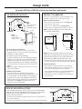
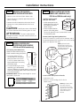
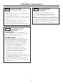
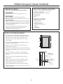
Design Guide with
Installation
Instructions
Fresh-Food Refrigerator
ZIFI240
ZIFS240
Bar Refrigerator with Icemaker
ZIBI240
ZIBS240
monogram.com
Safety Information
BEFORE YOU BEGIN:
WARNING:
Read these instructions completely and carefully.
• Use this appliance only for its intended purpose.
• Immediately repair or replace electrical service cords
that become frayed or damaged.
• Unplug the unit before cleaning or making repairs.
• Repairs should be made by a qualified service
technician.
IMPORTANT – Save these instructions
for local inspector’s use.
IMPORTANT – Observe all governing codes
and ordinances.
Note to Installer – Be sure to leave these
instructions with the Consumer.
Note to Consumer – Keep these instructions with
your Owner’s Manual for future reference.
AVERTISSEMENT :
• Il ne faut utiliser cet appareil que pour l’usage pour
lequel il a été construit.
• Il faut réparer ou remplacer immédiatement tout
cordon d’alimentation électrique effiloché ou
endommagé.
• Débranchez le réfrigérateur avant le nettoyage
ou toute intervention.
• Les réparations doivent être faites par un technicien
qualifié.
WARNING –
This appliance must be
properly grounded. See below.
AVERTISSEMENT –
Cet appareil doit être correctement mis à la terre.
Consulter ci-dessous.
If you received a damaged Fresh-Food Refrigerator
or Bar Refrigerator with Icemaker, you should
immediately contact your dealer or builder.
For Monogram local service in your area, call
1.800.444.1845
For Monogram service in Canada, call
1.800.561.3344
For Monogram Parts and Accessories, call
1.800.626.2002.
Skill Level – Installation requires basic mechanical
skills. Proper installation is the responsibility of the
installer. Product failure due to improper installation
is not covered under the GE Appliance Warranty.
monogram.com
GROUNDING THE FRESH-FOOD REFRIGERATOR OR BAR REFRIGERATOR
WITH ICEMAKER
IMPORTANT – Please read carefully.
FOR PERSONAL SAFETY, THIS APPLIANCE MUST BE PROPERLY GROUNDED.
The power cord of this appliance is equipped with a 3-prong (grounding) plug which mates with a standard 3-prong
(grounding) wall receptacle to minimize the possibility of electric shock hazard from this appliance.
Have the wall outlet and circuit checked by a qualified electrician to make sure the outlet is properly grounded.
Where a standard 2-prong wall outlet is encountered, it is your personal responsibility and obligation to have it replaced
with a properly grounded 3-prong wall outlet.
DO NOT, UNDER ANY CIRCUMSTANCES, CUT OR REMOVE THE THIRD
(GROUND) PRONG FROM THE POWER CORD.
DO NOT USE AN ADAPTER PLUG TO CONNECT THE REFRIGERATOR
TO A 2-PRONG OUTLET.
DO NOT USE AN EXTENSION CORD WITH THIS APPLIANCE.
2
Installation Instructions
CONTENTS
CARING FOR YOUR STAINLESS STEEL
Design Guide (For ZIFS240 and ZIBS240)
The Installation Space ............................................................................................4
Product Clearances ..................................................................................................4
Side-by-Side Installations ....................................................................................4
Design Guide (For ZIFI240 and ZIBI240)
The Installation Space ............................................................................................5
Product Clearances ..................................................................................................5
Side-by-Side Installations ....................................................................................5
Important Information
Parts Required..............................................................................................................3
Caring for Your Stainless Steel ..........................................................................3
Tools, Hardware ........................................................................................................3
Staining Wood Drawer Fronts ..........................................................................3
Install Water Line ......................................................................................................3
Installation Instructions
Step 1, Remove Packaging and Installation Parts ................................6
Step 2, Install Custom 3/4″ Door Panel and Handle
(ZIFI240 and ZIBI240 models only) ............................................................6, 7
Step 3, Leveling............................................................................................................7
Step 4, Connect Water Supply (ZIBI240 and ZIBS240 models only)..7
Step 5, Connect Power ..........................................................................................8
Step 6, Slide Product into Cutout......................................................................8
Step 7, Set Temperature Controls....................................................................8
ZTBSS1 Tubular Handle Kit ..................................................................................9
• Before installation or first use, we strongly advise that
you polish the stainless steel exterior and handle with
a commercially available stainless steel cleaner such as
Stainless Steel Magic.™ To preserve and protect the fine
finish, we also strongly advise that you apply stainless
steel cleaner monthly.
TOOLS/HARDWARE REQUIRED
• Adjustable wrench
• Carpenter’s glue (ZIFI240 and ZIBI240 models only)
• Screwdriver (ZIFI240 and ZIBI240 models only)
STAINING WOOD DRAWER FRONTS
The drawer fronts are unfinished cherry wood. During use,
oil from hands may accumulate and stain the wood.
• The drawer fronts may be stained and sealed to match
adjacent cabinetry.
• Apply the stain and sealer according to the manufacturer’s
instructions. To avoid unpleasant odor, keep the door open
to ventilate and allow the stain/sealer to dry completely
before using the product.
ZIFI240 AND ZIBI240 MODELS ONLY
PARTS REQUIRED
PARTS SUPPLIED
• Custom handle
• Assembled overlay panel
• Screws
• Handle side trim
• Optional black or
stainless steel toekick
INSTALL WATER LINE (ZIBI240 AND ZIBS240 MODELS ONLY)
• A cold water supply is required for automatic icemaker
operation. The water pressure must be between 20 and
120 p.s.i.
• The water line can enter the opening through
the floor or back wall. Route 1/4″ O.D. copper tubing or GE
SmartConnect™ kit between the cold water line and water
connection location, long enough to extend to the front of
the refrigerator.
• Install an optional water filter in the water line near the
refrigerator. A water filter is recommended in areas where
the water supply contains sand and particles. Installation
Instructions are packed with the filter.
NOTE: The only GE approved plastic tubing is supplied in
the GE SmartConnect™ Refrigerator Tubing kits. Do not use
any other plastic water supply line because the line is under
pressure at all times. Other types of plastic may crack or
rupture with age and cause water damage to your home.
GE SmartConnect™ Refrigerator Tubing Kits are available
in the following lengths:
2′ (0.6 m)
WX08X10002
15′ (4.6 m) WX08X10015
6′ (1.8 m)
WX08X10006
25′ (7.6 m) WX08X10025
Water Line
Water Line
Shaded Area
1/2"
Floor
9"
max.
10-1/2"
1-1/2"
min.
Shut off the main water supply.
Turn on the nearest faucet long enough to clear the line
of water.
• Install a shut-off valve (required) between the icemaker
water valve and cold water pipe in a basement or cabinet.
The shut-off valve should be located where it will be easily
accessible.
• Turn on the main water supply and flush debris. Run about
a quart of water through the tubing into a bucket. Shut off
water supply at the shut-off valve.
NOTE: Saddle type shut-off valves are included in many water
supply kits, but are not recommended for this application.
NOTE: Commonwealth of Massachusetts Plumbing Codes
248CMR shall be adhered to. Saddle valves are illegal and use
is not permitted in Massachusetts. Consult with your licensed
plumber.
3
Design Guide
For models ZIFS240 and ZIBS240 with Stainless Steel Doors and Handles
THE INSTALLATION SPACE
PRODUCT CLEARANCES
The Fresh-Food Refrigerator or Bar Refrigerator with
Icemaker is factory set for a 110° door swing.
Locate
Outlet
8-1/2"
10-1/2"
34-1/2"-35"
9"
9" Max.
Max.
24"
1-1/2"
1-1/2"
23-3/4" Min.
When installed in a corner:
• Allow 14″ minimum clearance on the hinge side
for a full 110° door swing.
• Allow 4″ min. clearance on the hinge side for
the 90° door swing and to allow racks to slide out.
NOTE: Clearances are based on the recommended
2-1/4″ handle standoff depth.
NOTE:
Water line location
for ZIBI240 or
ZIBS240 model only
23-3/4"
14" Minimum to Wall
NOTE:
Handle and
handle standoff 26"
depth is 2-1/4″. Including
Handle
90° Door
Swing
34-1/4"
to 34-3/4"
21-5/8"
110° Door
Swing
23-5/8"
23-3/4"
90°
110°
The cutout depth should be 24″
The cutout dimensions shown allow for a full door
swing and access to the pull-out racks when installed
in standard 24″ deep cabinets.
• All models may be used freestanding.
• If installing a stainless steel model between frameless
cabinets, a 1/2″ wide filler strip or side panel may be
needed on the hinge side. The filler strip will act as
a spacer between the case and adjacent cabinet door
swing. The width of the opening must include the filler
panels.
Note: The stainless steel door should be flush with the
surrounding cabinets.
4" Minimum to Wall
NOTE: Right hand models illustrated. Allow the same
clearances on the opposite side for left hand fresh food
models ZIFI240 and ZIFS240 only. Models ZIBI240 and
ZIBS240 are not available with left hand door swing.
• Test the door swing. Carefully open and close the door.
The door should not rub or catch on adjacent cabinetry.
Choose the location:
• These products may be closed in on the top and
three sides as long as the front is unobstructed for
air circulation and proper access to the door.
• Do not install these products where the temperature
will go below 55°F (13°C) or above 90°F (32°C).
• These products are not designed to be stacked one
over the other.
Additional Specifications
• A 120 volt 60Hz., 15 or 20 amp power supply is
required. An individual properly grounded branch circuit
or circuit breaker is recommended. Install a properly
grounded 3-prong electrical receptacle recessed into
the back wall as shown. Electrical must be located on
rear wall as shown. NOTE: GFCI (ground fault circuit
interrupter) is not recommended.
SIDE-BY-SIDE INSTALLATIONS
For a complete refreshment center, install a Fresh-Food Refrigerator
beside a Double Drawer Refrigerator, Beverage Center or Wine Chiller/
Wine Reserve. Or, install a Refrigerator with Icemaker beside
a Wine Chiller/Wine Reserve.
• A side-by-side installation requires at least a 47-1/2″ wide opening.
No trim kits required.
• Products must operate from separate, properly grounded receptacles.
4
Locate
Outlet
10-1/2"
10-1/2"
14"
34-1/2"-35"
15"
9"
9"
1-1/2"
47-1/2" Min.
24"
Design Guide
For models ZIFI240 and ZIBI240 with Custom Door Panels and Handles
PRODUCT CLEARANCES
THE INSTALLATION SPACE
The Fresh-Food Refrigerator or Bar Refrigerator with
Icemaker is factory set for a 110° door swing.
Locate
Outlet
8-1/2"
10-1/2"
34-1/2"-35"
9"
9" Max.
Max.
24"
1-1/2"
1-1/2"
23-3/4" Min.
When installed in a corner:
• Allow 16″ minimum clearance on the hinge side
for a full 110° door swing.
• Allow 4-1/2″ min. clearance on the hinge side for
the 90° door swing and to allow racks to slide out.
NOTE: Custom handle clearances may vary.
NOTE:
Water line location
for ZIBI240 or
ZIBS240 model only
16" Minimum to Wall
NOTE: If installing between
frameless cabinets, a 1/2″
wide filler strip or side panel
may be needed on the hinge
side. The filler strip will act as
a spacer between the door
case and adjacent cabinet
and will prevent interference
with the cabinet door swing. 24-7/8"
The width of the opening
must include the filler panels.
90° Door
Swing
21-5/8"
110° Door
Swing
34-1/4"
to 34-3/4"
23-5/8"
90°
23-3/4"
110°
The cutout depth should be 24″
The cutout dimensions shown allow for a full door
swing and access to the pull-out racks when installed
in standard 24″ deep cabinets.
• All models may be used freestanding.
• In a standard 24″ opening, the refrigerator door will
protrude 1-3/4″ forward of the adjacent cabinets.
4-1/2" Minimum to Wall
NOTE: Right hand models illustrated. Allow the same
clearances on the opposite side for left hand fresh food
models ZIFI240 and ZIFS240 only. Models ZIBI240 and
ZIBS240 are not available with left hand door swing.
• Test the door swing. Carefully open and close
the door. The door should not rub or catch on adjacent
cabinetry. NOTE: When installing custom panel and
handle, use above clearances as a general guide but
adjust according to the installation.
Choose the location:
• These products may be closed in on the top and
three sides as long as the front is unobstructed for
air circulation and proper access to the door.
• Do not install these products where the temperature will
go below 55°F (13°C) or above 90°F (32°C).
• These products are not designed to be stacked one
over the other.
Additional Specifications
• A 120 volt 60Hz., 15 or 20 amp power supply is
required. An individual properly grounded branch circuit
or circuit breaker is recommended. Install a properly
grounded 3-prong electrical receptacle recessed into
the back wall as shown. Electrical must be located on
rear wall as shown. NOTE: GFCI (ground fault circuit
interrupter) is not recommended.
Black or Stainless Steel Toekick Options
• These products are shipped with a stainless steel toekick
and a black toekick. For shipping purposes, one of the
toekicks will be secured to the back of the unit, and the
second will be installed on the unit. Keep the unused
toekick and any unused parts for future use.
ZTBSS1—Monogram stainless steel tubular handle
for 3/4″ thick custom panels. Order this kit from your
Monogram supplier.
SIDE-BY-SIDE INSTALLATIONS
For a complete refreshment center, install a Fresh-Food Refrigerator
beside a Double Drawer Refrigerator, Beverage Center or Wine Chiller/
Wine Reserve. Or, install a Refrigerator with Icemaker beside
a Wine Chiller/Wine Reserve.
• A side-by-side installation requires at least a 47-1/2″ wide opening.
No trim kits required.
• Products must operate from separate, properly grounded receptacles.
5
Locate
Outlet
10-1/2"
10-1/2"
14"
34-1/2"-35"
15"
9"
9"
1-1/2"
47-1/2" Min.
24"
Installation Instructions
STEP 1 REMOVE PACKAGING
AND INSTALLATION PARTS
STEP 2 INSTALL CUSTOM 3/4″ DOOR
PANEL AND HANDLE (CONT.)
(ZIFI240 and ZIBI240 models only)
• Remove corner blocks and foam drawer stops.
• Remove all packing material, tape and protective
plastic coverings.
• Remove the toekick attached to the back of the unit.
• Remove the custom panel attached to the front of
the unit.
Assemble overlay panels
Overlay Panel
with glue and screws.
• Center spacer panel on the
Spacer Panel
backer panel, left to right and
top to bottom. Secure the
panels with glue.
Backer Panel
• Center the spacer/backer
panel on the overlay panel.
Secure with glue and screws. Countersink all screws
into the backer panel.
CAUTION: Small objects are a choke hazard
for children. Remove and discard any parts not used.
ATTENTION : Les petits objets peuvent
étrangler les enfants. Il faut jeter toutes les pièces qui
ne sont pas utilisées.
Custom Panel Hinge Routing Dimensions
Use a 3/4″ router bit to cut a notch into the back side of
the assembled panel 3/8″ toward the front of the overlay
panel, 3/4″ deep and 7/8″ wide.
STEP 2 INSTALL CUSTOM 3/4″
DOOR PANEL AND HANDLE
NOTE: Right hand models
illustrated. Cut notches on the
opposite side for left hand fresh
food door swing models
ZIFI240 and ZIFS240.
(ZIFI240 and ZIBI240 models only)
3/4″ Overlay Panel Dimensions
Model ZIFI240 and ZIBI240 require
a field-installed overlay door panel.
Overlay
Panel
• The overlay panel must be
Door
secured to a 1/4″ thick backer
panel that slides into the trim.
A .10″ thick spacer panel must
be placed between the overlay
and backer panel.
1/4"
.10 Inch
Backer
• A custom handle of your choice,
Spacer
Panel
supplied by your cabinetmaker,
must be installed on this overlay panel. Countersink all
screws into the backer panel. Screws cannot protrude
from the backer panel.
IMPORTANT NOTE: Maximum total weight for custom
door panel is 25 pounds.
B
3/4″
7/8″
3/8″
3/8″
Back side
of custom
panel
7/8″
3/4″
Install custom door panel and handle:
• Open door to 90°.
• Remove 5 screws holding trim; lift off trim.
Retain screws.
3/4″ Overlay Panel Dimensions (in inches)
A (Width)
B (Height)
1/4″ Backer
23-3/16″
29-9/16″
0.10″ Spacer
22-1/2″
29-1/16″
3/4″ Overlay
23-5/8″
30″
NOTE: Right hand models
illustrated. Follow the
same instructions on the
opposite side for left hand
fresh food door swing
models ZIFI240 and
ZIFS240.
A
6
Installation Instructions
STEP 2 INSTALL CUSTOM 3/4″ DOOR
PANEL AND HANDLE (CONT.)
STEP 3 LEVEL
• Use an adjustable wrench
to turn the leveling legs and
raise or lower the product.
For built-in installation, adjust
the leveling legs slightly below
the bottom of the countertop.
INSTALLATION TIP:
Measure floor to underside
of countertop inside the
opening. If the room floor
Turn Right to Lower
is higher than the opening
Turn Left to Raise
floor, adjust the rear
leveling legs approximately
1/8" less than the opening height. Screw front legs all
the way in to shorten the height at the front. This will
allow you to slightly tip the unit into the opening. Once
in the correct position, the front legs can be adjusted to
level the product.
(ZIFI240 and ZIBI240 models only)
Install custom door panel and handle (cont.):
• A custom handle of your choice, supplied by your
cabinetmaker, must be installed onto the overlay panel
before the panels are slid into the trim. Countersink all
screws into the backer panel. Screws cannot protrude
from the backer panel.
Screws Must
Be Countersunk
Into Panel
Handle
Custom
Door Panels
• Slide overlay panel into the door trim.
STEP 4 CONNECT WATER SUPPLY
(ZIBI240 and ZIBS240 models only)
1/4″ Tubing
1/4″
Compression
Nut
Ferrule
(sleeve)
• Reinstall the side trim using the trim screws removed
earlier.
SmartConnect ™
Tubing
Refrigerator
Connection
• Locate and bring the water line tubing to the rear
of the cabinet.
• Turn the water on to flush debris from the line.
Run about a quart of water through the tubing
into a bucket, then shut off the water.
Copper Tubing:
• Slip a 1/4″ nut and ferrule over both ends of the copper
tubing. Insert the tube into the refrigerator connection
on the unit and tighten the nut.
• Turn on the water to check for leaks.
• Place the brushed decorative cover over the side trim
to hide the screw heads. Ensure side trim is aligned top
to bottom and front to back. Snap into place.
NOTE:
For shipping
purposes, the
brushed decorative
cover will be
secured to
the front of
the unit.
GE SmartConnect ™ Tubing:
• Insert the molded end of the tubing into the
refrigerator connection. Tighten the compression nut
until it is just hand tight.
• Tighten one additional turn with a wrench.
Overtightening can cause leaks!
• Turn on the water to check for leaks.
NOTE: Coil excess tubing length behind the unit.
7
Installation Instructions
STEP 5 CONNECT POWER
STEP 7 SET TEMPERATURE
CONTROLS
• Connect power cord plug to a properly grounded
receptacle.
• Check to make sure power is on by opening the door
to see if interior light turns on.
• Bar Refrigerator with Icemaker – The interior fan runs
all the time except during defrost cycle when the door
is open.
• Fresh-Food Refrigerator – The interior fan runs
all the time except when the door is open.
See the Owner’s Manual for further explanation of the fan.
• The temperature controls are preset. Refer to
the Owner’s Manual for more information. Allow
12–24 hours for the temperature to stabilize.
NOTE: The Fresh-Food Refrigerator or Bar Refrigerator with
Icemaker operate very quietly. You may not notice the unit
running, and when first installed, the fans and motor may
not come on immediately – this is normal. If the display is
lit and the light is working, the unit is operating.
STEP 6 SLIDE PRODUCT INTO
THE CUTOUT
CAUTION: Do not push against the door
panel with your knees. Do not push or lift the unit by
the door handle. Damage may occur!
ATTENTION : Ne poussez jamais
le panneau de la porte avec vos genoux. Ne poussez
jamais votre appareil ou ne le soulevez jamais par
la poignée de porte. Vous pouvez l’endommager.
• Open the door and gently push the unit back into
the opening with your hands against the sides.
Be careful not to entangle power cord.
• In a standard 24″ opening, the front face of
the stainless steel door will be flush with adjacent
cabinetry. A custom panel door may protrude
1-3/4″ beyond the surrounding cabinets.
• Check again to be sure the unit is level.
• If the unit is installed under a countertop, adjust
the leveling legs until the unit is resting firmly against
the underside of the countertop.
• If alignment with adjacent cabinetry is an issue,
use a shim to secure the unit against the underside
of the countertop.
8
ZTBSS1 Monogram Tubular Handle Kit
•
•
BEFORE YOU BEGIN:
TOOLS AND MATERIALS REQUIRED:
Read these instructions completely and carefully.
• Gloves to protect against sharp edges
• #2 Phillips screwdriver
• Drill and 1/4″ bit and 1/2″ spade bit
• Safety glasses
• Center punch
• Pencil
IMPORTANT:
Save these instructions for local inspector’s use.
•
IMPORTANT:
Observe all governing codes and ordinances.
• Note to Installer – Be sure to leave these instructions
with the Consumer.
• Note to Consumer – Keep these instructions with your
Owner’s Manual for future reference. This kit provides a
stainless steel tubular handle to coordinate with other
Monogram appliances.
THIS KIT INCLUDES
• Tubular handle
• 2 Mounting screws
• 2 Handle standoffs
• 2 Set screws for standoffs
• 2 Nuts
• 2 Washers
• Allen Wrench
• The tubular handle must be installed onto the 3/4″
thick portion of the custom wood panel before
the panel is secured to the door.
INSTALL THE TUBULAR HANDLE
• Use the handle as a template to locate and mark the
exact position of the screw holes. Be careful to avoid
interference with custom panel mounting screws.
7/8”
• Draw a pencil line, top to bottom and 7/8″ from the
outside edge.
30”
24-7/32”
• Hold the tubular handle against the appearance side,
centered on the marked line.
• Mark the screw hole locations at the center of the
handle attachment posts.
• Center punch the marked hole locations. Drill 1/4″ pilot
holes from the appearance side through the entire panel
thickness.
Custom
Framed
Panel
• Use a 1/2″ spade bit to drill 1/4″ to 5/16″ deep into
the back side of the panel. Insert washer (spacer) into
the hole.
Tubular
Handle
Handle
Standoff
• Install screw through the handle standoff and into
the pilot hole.
Handle
Attachment
Post
Washer
• Fasten nut onto the screw until the standoff is tight
against the panel. The screw hole on the standoff
should be pointing down toward the floor.
Nut
• Place handle attachment posts inside the standoffs.
Screw
• Use the Allen wrench to install the set screws. Tighten
handle to standoffs.
9
Set
Screw
Notes
10
Notes
11
NOTE: While performing installations described in this book,
safety glasses or goggles should be worn.
For Monogram® local service in your area, call
1.800.444.1845.
NOTE: Product improvement is a continuing endeavor
at General Electric. Therefore, materials, appearance
and specifications are subject to change without notice.
Pub. No. 31-51544-5
Part No. 197D5893P002
08-07 JR
Printed in Slovenia
GE Consumer & Industrial
Appliances
General Electric Company
Louisville, KY 40225
ge.com