1
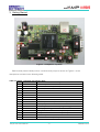
Users Manual
Design Gateway Co., Ltd.
Revision 1.3
(PD0606-6-00-01)
*** Please read this manual carefully before using JampII-mini ***
Revision History
Revision
Update-time
1.0
11 October 2549
Initial Release
1.1
10 January 2550
Update Install Redboot, Linux and rootfs
1.2
12 January 2550
Update jumper and connector cable
1.3
30 January 2550
Add board picture and connector layout description.
Recheck data in all table.
JampII-mini Users Manual
Description
-I-
PD0606-6-00-01
Table of Contents
1. Introducing JampII-mini Single Board Computer.............................................................................1
1.1. Software Requirement ..............................................................................................................1
1.2. Warranty Policy.........................................................................................................................1
1.3. Customer Support ....................................................................................................................1
2. JampII-mini Overview .......................................................................................................................2
2.1. Advanced Features ..................................................................................................................2
3. Getting Started..................................................................................................................................5
3.1. Assembly and Connections .....................................................................................................6
3.2. Operation..................................................................................................................................6
3.3. Configurations...........................................................................................................................6
4. JampII-mini Function Blocks.............................................................................................................8
4.1. EP9302......................................................................................................................................8
4.2. SDRAM .....................................................................................................................................8
4.3. FLASH.......................................................................................................................................9
4.4. USB...........................................................................................................................................9
4.5. UART 0 and 1 ...........................................................................................................................9
4.6. Ethernet...................................................................................................................................10
4.7. On-chip A/D............................................................................................................................10
4.8. GPIO .......................................................................................................................................10
4.9. Expansion Bus Connector......................................................................................................11
4.10. JTAG .......................................................................................................................................13
4.11. Power Requirement ................................................................................................................13
5. Software Description.......................................................................................................................14
5.1. Overview.................................................................................................................................14
5.2. JampII-mini Linux Code..........................................................................................................14
5.3. Redboot ..................................................................................................................................14
5.4. Download Utility......................................................................................................................14
5.5. minicom ..................................................................................................................................15
5.6. Boot-up JampII-mini ...............................................................................................................15
JampII-mini Users Manual
- II -
PD0606-6-00-01
6. Development Tools .........................................................................................................................17
6.1. Overview.................................................................................................................................17
6.2. Linux Development Tool Chain ..............................................................................................17
6.3. Host Computer Requirement..................................................................................................17
6.4. Hardware Connection.............................................................................................................17
6.5. Install Software Development Kit............................................................................................17
6.6. Loading Redboot....................................................................................................................18
6.7. Loading Linux Kernel, Root File System and boot script.......................................................18
6.8. Compile Linux Kernel .............................................................................................................20
6.9. Compile Redboot....................................................................................................................20
7. Application Development ...............................................................................................................22
7.1. Compile Application ...............................................................................................................22
7.2. Transfer and Running application on JampII-mini.................................................................22
8. Troubleshooting ..............................................................................................................................23
JampII-mini Users Manual
- III -
PD0606-6-00-01
1. Introducing JampII-mini Single Board Computer
JampII-mini Engineering Development Board is convenient and easy-to-operate evaluation
platform. JampII-mini provides the user with the ability to evaluate the EP9302 capabilities, and feature
set, which is delivered through a system, oriented engineering development board. Peripheral devices
such as analog audio input, analog audio output, 10/100 Ethernet, and RS-232 provide an effective
way to evaluate the EP9302 in a complete system environment. JampII-mini Development Board Kit
contains the following items:
- JampII-mini Board (See Processor Board section below for further details)
- Accessories
Power Supply +5V, 2A, 220V
Serial Cross Cable
LAN Cross Cable
Documentation and SDK CD
Getting Started Paper
All documentation, schematics, software, utilities, and related information is available from the
download section of the Cirrus Logic ARM Developer's web site, http://arm.cirrus.com and DesignGateway web site, http://www.design-gateway.com
1.1. Software Requirement
- Linux Fedora core 4: Workstation or add package development tools.
1.2. Warranty Policy
1. Product warranty is valid for 1 year from purchasing dare.
2. Warranty is void if any modification has been made to this product and any incorrect
operation from this manual or warranty sticker is torn or damaged.
3. In order to claim for product exchange or technical support within warranty period, official
receipt is required for unregistered customer as an evidence of purchasing whereas official
receipt is unnecessary for registered customer(please fill up registration card attached
herewith the product and send back to Design Gateway Co., Ltd.)
1.3. Customer Support
Customer can contact to [email protected] for support of any problem about JampIImini or visit our website at http://www.design-gateway.com.
JampII-mini Users Manual
-1-
PD0606-6-00-01
2. JampII-mini Overview
JampII-mini a low cost compact sized single board computer based on Cirrus Logic EP9302
processor. With a large peripheral set targeted to a variety of applications, JampII-mini is well suited
for industrial controls, digital media servers, audio jukeboxes, thin clients, point-of-sale terminals,
biometric security systems, and GPS devices will benefit from the EP9302's integrated architecture
and advanced features.
2.1. Advanced Features
The heart of JampII-mini is the EP9302 which is the one in a series of ARM920T based
processors. The ARM920T microprocessor core with separate 16 Kbytes 64-way set-associative
instruction and data caches is augmented by the MaverickCrunch™ coprocessor. This enables faster
than real-time compression of audio CDs. The proprietary MaverickKey™ unique hardware
programmed IDs provide an excellent solution to the growing concern over secure Web content and
commerce. MaverickKey IDs can also be used by OEMs and design houses to protect against design
piracy by presetting ranges for unique IDs.
The EP9302 is a high-performance, low-power RISC-based device built around a single
ARM920T microprocessor core. The ARM920T on the EP9302 functions with a maximum operating
clock rate of 200MHz and a power usage between 100mW and 750mW (dependent upon clock
speed). The ARM core operates from a 1.8V supply while the I/O operates at 3.3V. The low power
consumption makes it an idea platform for battery operated applications.
A high performance 1/10/100 Mbps Ethernet Media Access Controller (EMAC) is included
along with external interfaces to SPI and I2S Audio. A two-port USB host and two UART are included
as well.
The EP9302 is a high-performance, low-power RISC-based device built around an ARM920T
microprocessor core with a maximum clock rate of 200 MHz. The ARM core operates from a 1.8V
supply, while the I/O operates at 3.3V with a power usage between 100mW and 675mW.
The list below summarizes the features of JampII-mini.
- 200 MHz ARM920T Processor
16 Kbyte Instruction Cache
16 Kbyte Data Cache
Linux®, Microsoft® Windows® CE enabled MMU
100 MHz System Bus
JampII-mini Users Manual
-2-
PD0606-6-00-01
· MaverickCrunch™ Math Engine
· MaverickKey™ Security
- Integrated Peripheral Interfaces
SDRAM 16-bit 32MB
FLASH 16-bit 8 MB
Serial EEPROM 128kB (Optional)
Ethernet 10/100 Mbps
One UART RS232, one UART RS232/485
Two-port USB2.0 Full Speed Host (OHCI) (12 Mbits per second)
5 channel 12-bit Analog-to-Digital Converter Input
Audio input/output Interface (AC97) (Optional)
- Internal Peripherals
12 Direct Memory Access (DMA) Channels
Real-time Clock with software trims
Dual PLL controls all clock domains
Watchdog Timer
Two general purpose 16-bit timers
One general purpose 32-bit timer
One 40-bit Debug Timer
Interrupt Controller
Boot ROM
EP9302
JampII-mini is shipped with the Cirrus Logic EP9302 processor. For more information
regarding the EP9302 processor please see the EP9302 datasheet.
SDRAM
JampII-mini is shipped with 32MBytes of SDRAM.
FLASH
JampII-mini is shipped with 8MBytes of asynchronous Intel Strata-Flash.
EEPROM
The EDB9302 support serial EEPROM. This EEPROM can be used for parameter
storage or boot-code.
JampII-mini Users Manual
-3-
PD0606-6-00-01
USB
JampII-mini is shipped with two USB host connections.
UART 1
JampII-mini is shipped with a 9-pin interface.
UART 2
JampII-mini is shipped with the 3 wire UART 1 interface.
Audio Input (Optional)
JampII-mini is shipped with a single stereo audio input.
Audio Output (Optional)
JampII-mini is shipped with a single stereo audio output.
Ethernet
JampII-mini is shipped with a complete physical and MAC subsystem that is compliant
with the ISO/TEC 802.3 topology for a single shared medium with several stations. The EP9302
supports 1/10/100 Mbps transfer rates and interfaces to industry standard physical layer.
JampII-mini Users Manual
-4-
PD0606-6-00-01
3. Getting Started
Figure 3-1 JampII-mini Top View
Before starts please identify switch, connector and jumper as shown in Figure3-1, there
descriptions are listed in the following table.
Table 3-1 Switch, connector and jumper name
Item
Name
Description
A
J1
DC Jack input 5V
B
JP1
Boot mode selection (ASDOUT)
C
JP12
HDLC COF selection
D
JP11
HDLC INT selection
E
SW2
Power on reset switch
F
SW1
System reset switch
G
J3
GPIO connector
H
J6
Expansion bus connector
I
J11
UART output selector (RS-232 / RS-485)
J
J2
ADC input port
K
JP13
Connect system reset to JTAG programming port
L
J4
JTAG programming port
M
J8
Full speed USB device connector (USB1)
N
J9
Full speed USB device connector (USB0)
O
J13
RS-232 output
P
JP9
Boot mode selection (EECLK)
JampII-mini Users Manual
-5-
PD0606-6-00-01
Q
R
S
T
U
V
JP10
JP5
JP4
J14
J10
J5
Factory test input
Boot mode selection (BOOT 0)
Boot mode selection (BOOT 1)
DB9 RS-232 output
RS-485 output
Ethernet port connector
3.1. Assembly and Connections
In order to use JampII-mini, the user must first assemble and connect the peripherals to
JampII-mini, as described in the following procedure.
1. Place JampII-mini on a static free surface.
2. Make sure all of the jumpers are in the default position. See Table3-2 for more on jumper
setting.
3. Connect 5V regulated power supply to the board.
4. Connect serial cross cable between JampII-mini UART 1 (J13) and PC/terminal serial port.
5. Launch a terminal program such as HyperTerminal on the PC. Configure the serial port with the
following parameters: 57600 bits per second, 8 data bits, no parity, 1 stop bit, no flow control.
6. Connect the board to a local area network (optional). User can connect JampII-mini directly to
one computer with cross cable, or use ordinary Ethernet cable connects JampII-mini to hub.
3.2. Operation
When power is first apply all LED in JampII-mini will light up, after a short period the red LED
will turn off. If the red LED turns on for a very long period after power up, it is possible that hardware
may already damage. In this case, please contact Design Gateways tech support ([email protected]).
A few second after red LED turn off, the debug information will be displayed on the terminal
program. For more detail about software functionality, please see Chapter 5 Software Description
3.3. Configurations
Jumpers are used to configure JampII-mini to operate in different mode. The following table
lists all the settings for each jumper.
JampII-mini Users Manual
-6-
PD0606-6-00-01
Table 3-2 Jumper setting
Jumper
Function
JP1
ASDO
JP4
JP5
BOOT[1]
BOOT[0]
JP9
EECLK
JP10
JP13
Factory Test
JTAG Reset
JampII-mini Users Manual
Description
1-2 = boot from synchronous memory
2-3 = boot from asynchronous memory
2-3 = always use this configuration
1-2 = serial boot mode
2-3 = parallel boot mode
Open = Boot from internal boot code first
Short = Boot from external boot ROM directly
For factory test only, should left open in normal condition.
Open = Disable reset signal form JTAG connector
Short = Enable reset signal from JTAG connector
-7-
PD0606-6-00-01
4. JampII-mini Function Blocks
4.1. EP9302
JampII-mini Single Board Computer uses the Cirrus Logic EP9302 as the core processor on this
development board. The top-level features of EP9302 processor are the following:
· ARM920T RISC Core Processor
· 200 MHz / 200 MIPS Performance
· 16 Kbyte Instruction Cache
· 16 Kbyte Data Cache
· Linux and Windows CE enabled MMU
Note: Cirrus Logic to supply either a Linux port or a Windows CE port, including the
respective board support package (BSP).
· 100 MHz System Bus
· MaverickCrunchTM Math Engine
· MaverickKeyTM Security Features
· 16 bit SDRAM Interface (Up To 4 Banks)
· 16 bit SRAM / FLASH / ROM Interface
· Serial EEPROM Interface
· 10 / 100 Mbps Ethernet MAC
· Two UART
· Two-port USB Host
· 5 channel 12 bit ADC
· SPI Port
· Serial Audio Interface
· JTAG Interface
More detailed information regarding the EP9302 processor can be found at www.cirrus.com and
on the enclosed disk.
4.2. SDRAM
JampII-mini Users Manual
-8-
PD0606-6-00-01
The EP9302 features a unified memory address model where all memory devices are accessed
over a common address and data bus. The EP9302 can support a minimum of 1 to a maximum of 4
banks of 16-bit 100 MHz SDRAM. Additionally, JampII-mini installed with 32 MB SDRAM density.
4.3. FLASH
As previously stated, the EP9302 features unified memory address architecture. The EP9302 can
support either NAND or NOR types of non-volatile flash memory for program code storage. JampIImini is shipped with 8 Mbytes of flash memory, which is provided by Intel Strata FLASH memory
device.
4.4. USB
JampII-mini Single Board Computer provides two USB host connections (USB0-J9, USB1-J8).
The EP9302 USB host controller is configured for two root hub ports and features an integrated
transceiver for each port. The EP9302 integrates two USB 2.0 Full Speed host ports. These ports are
fully compliant to the OHCI USB 2.0 Full Speed specification (12 Mbps). The controller complies with
the OHCI specification for USB Revision 1.1. The USB ports are brought out by a standard double
deck USB type A connector.
4.5. UART 0 and 1
JampII-mini Single Board Computer is shipped with 2 UART interface. The UART 1 interface is
provided via a standard DB-9 connector. The signal designation is listed in the following tables.
Table 4-1 UART0 Connector (J14)
Pin No.
Signal Name
Pin No.
Signal Name
1
Not connect
2
RX
3
TX
4
Not connect
5
GND
6
Not connect
7
RTS
8
CTS
9
Not connect
JampII-mini Users Manual
-9-
PD0606-6-00-01
Table 4-2 UART1 Connector (J13)
Pin No.
Signal Name
Pin No.
Signal Name
1
TX
2
RX
3
GND
4.6. Ethernet
JampII-mini Single Board Computer is shipped with support for a complete Ethernet interface.
The EP9302 contains a MAC subsystem that is compliant with the ISO/TEC 802.3 topology for a single
shared medium with several stations. The Media Access Controller (MAC) within the EP9302 supports
1/10/100 Mbps transfer rates and interfaces to industry standard physical layer devices. JampII-mini is
shipped with a RJ45 connector, provides the physical layer interface.
4.7. On-chip A/D
JampII-mini Single Board Computer is shipped with a 5 channel 12 bit on-chip A/D converter.
The signal designation is listed in the following table.
Table 4-3 A/D Input Connector (J2)
Pin Number
Signal Name
Pin Number
Signal Name
1
Channel 2
2
Channel 4
3
Channel 1
4
Channel 3
5
Channel 0
6
Channel AGND
4.8. GPIO
JampII-mini Single Board Computer provides 20 general purpose I/O signals for external use.
The signal designation is listed in the following tables.
Table 4-4 GPIO Connector (J3) Signal List
Pin Number
Signal Name
Pin Number
Signal Name
1
3.3V
2
3.3V
3
EGPIO 5
4
EGPIO 9
5
CGPIO
6
EGPIO 8
7
EGPIO 3 / HDLC
8
EGPIO 2
9
FGPIO 0
10
EGPIO 4
JampII-mini Users Manual
- 10 -
PD0606-6-00-01
11
EGPIO 14
12
FGPIO 1
13
FGPIO 2
14
EGPIO 13
15
HGPIO 1
16
HGPIO 0
17
HGPIO 3
18
HGPIO 2
19
GND
20
GND
4.9. Expansion Bus Connector
The expansion bus connector is for system expansion, user can built their sub-system and
connect with JampII-mini through memory map the maximum bus width is 16-bit. The pin list and their
signal name are list in the following table.
JampII-mini Users Manual
- 11 -
PD0606-6-00-01
Table 4-5 Expansion Connector (J6) Signal List
Pin Number
1
3
5
7
9
11
13
15
17
19
21
23
25
27
29
31
33
35
37
39
41
43
45
47
49
Signal Name
GND
Data0
Data1
Data2
Data3
Data4
Data5
Data6
Data7
GND
Address0
Address2
Address4
Address6
Address8
Address10
Address12
Address14
GND
Read enable (active low)
Wait (active low)
Chip select 6
EGPIO12
EGPIO11
GND
JampII-mini Users Manual
Pin Number
2
4
6
8
10
12
14
16
18
20
22
24
26
28
30
32
34
36
38
40
42
44
46
48
50
- 12 -
Signal Name
GND
Data15
Data14
Data13
Data12
Data11
Data10
Data9
Data8
GND
Address1
Address3
Address5
Address7
Address9
Address11
Address13
Address15
GND
Write enable (active low)
Chip select 0
EGPIO15
EGPIO10
GND
GND
PD0606-6-00-01
4.10. JTAG
JampII-mini Single Board Computer is shipped with 8 pin JTAG connector. The JTAG provides
the user with the ability to debug system level programs. The signal designation is listed in the
following table.
Table 4-6 JTAG Connector Signal List
Pin Number
Signal Name
Pin Number
Signal Name
1
3.3V
2
TRST
3
TDI
4
TMS
5
TCK
6
TDO
7
RST
8
GND
4.11. Power Requirement
JampII-mini Single Board Computer requires regulated 5v DC.
Table 4-7 Power Supply Connector (J1)
JampII-mini Users Manual
Pin Number
Signal Name
1
5V DC
2
GND
- 13 -
PD0606-6-00-01
5. Software Description
5.1. Overview
This chapter provides information regarding the software that is shipped with JampII-mini
Board. The software included with the board is Linux with a few test applications and network utilities.
The Linux software provides the user with the ability to test some of the subsystems on JampII-mini
board. The download utility provides a means to program a binary image into the flash memory on
JampII-mini.
5.2. JampII-mini Linux Code
The pre-programmed software provides the user with the opportunity to test some of the
subsystems on JampII-mini via Linux. This software is programmed into the system FLASH located on
the board prior to shipment. The binary image of the shipped code is included on the CD that ships
with the board.
5.3. Redboot
RedBoot provides a simple interface for loading operating systems and applications onto
JampII-mini board. It can also serve as a debug platform for standalone programs using the GDB stub
that is built into RedBoot. RedBoot uses a serial console for its input and output. The default serial port
setting is 57600,8,N,1. It also supports the built-in Ethernet port and a flash file system and general
flash programming. The board is shipped with Redboot pre-installed. Please refer to Download Utility
section for instructions to reload Redboot. Please refer to documents at ECOS website
http://ecos.sourceware.org regarding how to rebuild Redboot.
5.4. Download Utility
The download utility provides the user with a tool for programming the flash memory on JampIImini with a binary image.
JampII-mini Users Manual
- 14 -
PD0606-6-00-01
5.5. minicom
minicom is a communication program which somewhat resembles the shareware program
TELIX but is free with source code and runs under most unices. Features include dialing directory
with auto-redial, support for UUCP-style lock files on serial devices, a seperate script language
interpreter, capture to file, multiple users with individual configurations, and more.
5.6. Boot-up JampII-mini
First, connect serial cross-cable between PC and JampII-mini. Run LminicomM terminal
application. Set baud rate 57600,8,N,1 non flow control. Next, power on JampII-mini board
+Ethernet eth0: MAC address 00:00:00:00:cc:33
IP: 192.168.11.250/255.255.255.0, Gateway: 192.168.11.254
Default server: 192.168.11.100, DNS server IP: 192.168.11.254
RedBoot(tm) bootstrap and debug environment [ROMRAM]
Non-certified release, version v2_0 - built 00:32:21, Jan 11 2007
Platform: Cirrus Logic EDB9302A Board (ARM920T) Rev A
Copyright (C) 2000, 2001, 2002, Red Hat, Inc.
RAM: 0x00000000-0x02000000, 0x00041e68-0x01fdd000 available
FLASH: 0x60000000 - 0x60800000, 64 blocks of 0x00020000 bytes each.
== Executing boot script in 3.000 seconds - enter ^C to abort
RedBoot> fis load initrd
RedBoot> fis load zImage
RedBoot> exec -r 0x01000000 -s 0x400000 -c "console=ttyAM0,57600 root=/dev/ram
rw"
Using base address 0x00100000 and length 0x0010d19c
Uncompressing Linux.............................................................
............. done, booting the kernel.
Linux version 2.6.8.1-crus2.0.2 ([email protected]) (gcc version 3.4.3)
#1 Wed Jan 10 20:53:07 ICT 2007
CPU: ARM920Tid(wb) [41129200] revision 0 (ARMv4T)
CPU: D VIVT write-back cache
CPU: I cache: 16384 bytes, associativity 64, 32 byte lines, 8 sets
CPU: D cache: 16384 bytes, associativity 64, 32 byte lines, 8 sets
Machine: edb9302A
Memory policy: ECC disabled, Data cache writeback
bank 0 start at 0xc0000000, length 0x00800000, mapped to 0xc0000000
bank 1 start at 0xc1000000, length 0x00800000, mapped to 0xc1000000
bank 2 start at 0xc4000000, length 0x00800000, mapped to 0xc4000000
bank 3 start at 0xc5000000, length 0x00800000, mapped to 0xc5000000
Built 1 zonelists
Kernel command line: console=ttyAM0,57600 root=/dev/ram rw
PID hash table entries: 512 (order 9: 4096 bytes)
Console: colour dummy device 80x30
Dentry cache hash table entries: 8192 (order: 3, 32768 bytes)
Inode-cache hash table entries: 4096 (order: 2, 16384 bytes)
Memory: 8MB 8MB 8MB 8MB = 32MB total
Memory: 25800KB available (1875K code, 502K data, 80K init)
Calibrating delay loop... 99.73 BogoMIPS
Mount-cache hash table entries: 512 (order: 0, 4096 bytes)
CPU: Testing write buffer coherency: ok
checking if image is initramfs...it isn't (no cpio magic); looks like an initrd
Freeing initrd memory: 4096K
NET: Registered protocol family 16
SCSI subsystem initialized
usbcore: registered new driver usbfs
usbcore: registered new driver hub
NetWinder Floating Point Emulator V0.97 (double precision)
JFFS version 1.0, (C) 1999, 2000 Axis Communications AB
JampII-mini Users Manual
- 15 -
PD0606-6-00-01
JFFS2 version 2.2. (C) 2001-2003 Red Hat, Inc.
ttyAM0 at MMIO 0x808c0000 (irq = 52) is a EP93XX
ttyAM1 at MMIO 0x808d0000 (irq = 54) is a EP93XX
ttyAM2 at MMIO 0x808e0000 (irq = 55) is a EP93XX
RAMDISK driver initialized: 16 RAM disks of 32768K size 1024 blocksize
loop: loaded (max 8 devices)
Using anticipatory io scheduler
edb93xxflash0: Found 1 x16 devices at 0x0 in 16-bit bank
Intel/Sharp Extended Query Table at 0x0031
cfi_cmdset_0001: Erase suspend on write enabled
Using buffer write method
6 RedBoot partitions found on MTD device edb93xxflash0
Creating 6 MTD partitions on "edb93xxflash0":
0x00000000-0x00040000 : "RedBoot"
0x00040000-0x00200000 : "zImage"
0x00200000-0x00600000 : "initrd"
0x00600000-0x007c0000 : "unallocated"
0x007c0000-0x007c1000 : "RedBoot config"
0x007e0000-0x00800000 : "FIS directory"
ep93xxusb ep93xxusb0: new USB bus registered, assigned bus number 1
hub 1-0:1.0: USB hub found
hub 1-0:1.0: 3 ports detected
usbcore: registered new driver usbhid
drivers/usb/input/hid-core.c: v2.0:USB HID core driver
ep93xx_udc: version 28-6-2005
USB Device Controller Chip ID :ffff test chipID is wrong
Are you sure the USB2 Slave Daughter Board Link on EDB931X?
ep93xx-udc: probe of ep93xx-udc0 failed with error -16
mice: PS/2 mouse device common for all mice
Advanced Linux Sound Architecture Driver Version 1.0.4 (Mon May 17 14:31:44 2004
UTC).
Cirrus Logic ep93xx i2s audio initialized
ALSA device list:
#0: Cirrus Logic ep93xx i2s audio
NET: Registered protocol family 2
IP: routing cache hash table of 512 buckets, 4Kbytes
TCP: Hash tables configured (established 2048 bind 4096)
NET: Registered protocol family 1
NET: Registered protocol family 17
RAMDISK: Compressed image found at block 0
EXT2-fs warning: feature flags set on rev 0 fs, running e2fsck is recommended
VFS: Mounted root (ext2 filesystem).
Freeing init memory: 80K
init started: BusyBox v1.1.3 (2007.01.10-17:20+0000) multi-call binary
eth0: No network cable detected!
Please press Enter to activate this console.
BusyBox v1.1.3 (2007.01.10-17:20+0000) Built-in shell (ash)
Enter 'help' for a list of built-in commands.
~ #
JampII-mini Users Manual
- 16 -
PD0606-6-00-01
6. Development Tools
6.1. Overview
This chapter provides a brief introduction to development tools that are available for the
EP9302 System-on-a-Chip processor. The central processing core on the EP9302 is a 200 MHz
ARM920T processor. The ARM920T RISC processing core is supported through various toolsets
available from third party suppliers. The typical toolset required for the code development is a
compiler, assembler, linker and a source-level code debugger. Code debugging is supported via the
on-chip JTAG interface.
6.2. Linux Development Tool Chain
The Linux development tool chain is included in the CD ROM come with JampII-mini board. A
host PC running Linux operating system is required to run the development tools. This guide assumes
user had basic Linux or Unix application development knowledge.
6.3. Host Computer Requirement
The host PC should run Redhat, SuSe, or other Linux distribution, a RS-232 serial port, at least
1GB free disk space, and a terminal program such as minicom.
6.4. Hardware Connection
A serial cross cable is required to connect JampII-mini to the host computer.
6.5. Install Software Development Kit
The ARM Linux Software Development Kit can be installed in any directory on the host system.
The following installing the ARM Linux Development software package.
1. Insert cd-rom SDK of JampII-mini
2. Copy and setup software package, executing the following commands,
#
#
#
#
#
mount /cdrom
mkdir /opt/jampII-mini
cp /cdrom/* /opt/jampII-mini/ –R (you can copy to another path)
cd /opt/jampII-mini
./setup.sh
*Your mounting point of CD-ROM maybe different
JampII-mini Users Manual
- 17 -
PD0606-6-00-01
3. Set up the directory path variable
# export PATH=$PATH:/usr/local/arm/3.4/bin:/usr/local/arm/3.2.1-elf/bin
The above command can be included in the shell resource file so it is executed every time you
login. For bash shell, a good place to put is in .bashrc in your home directory.
6.6. Loading Redboot
The following procedure will allow in-circuit programming of the flash memory via the EP9302
processor:
1) Power the board off.
2) Connect serial cross cable to UART1.
3) Set jumper 5 to connect pin 1 and 2 (JP5 factory default is pin 2 and 3).
4) Stop any program that might use the serial port that is connected to JampII-mini.
5) Run download utility (assuming download located in same directory as binary image)
# cd ./firmware
# ./download -b 57600 redboot.bin
*more detail use L./download --helpM
6) LWaiting for the board to wakeup...M message is displayed.
7) Power the board on.
8) Messages displayed regarding erasing, then programming the flash.
9) LSuccessfully programmed redboot.binM message displayed upon programming completion.
10) Power the board off.
11) Install jumper on pin 2 and 3 of JP5.
12) Power the board on.
6.7. Loading Linux Kernel, Root File System and boot script
The Redboot boot-loader provides to load Linux kernel and file system into FLASH memory, by
serial connection method can be used.
After power on JampII-mini board, the following message should be shown on the terminal
console on the host PC connected to JampII-mini board.
+EP93xx - no EEPROM, static ESA, or RedBoot config option.
No network interfaces found
JampII-mini Users Manual
- 18 -
PD0606-6-00-01
RedBoot(tm) bootstrap and debug environment [ROMRAM]
Non-certified release, version v2_0 - built 00:32:21, Jan 11 2007
Platform: Cirrus Logic EDB9302A Board (ARM920T) Rev A
Copyright (C) 2000, 2001, 2002, Red Hat, Inc.
RAM: 0x00000000-0x02000000, 0x00041e68-0x01fdd000 available
FLASH: 0x60000000 - 0x60800000, 64 blocks of 0x00020000 bytes each.
RedBoot>
A slightly different message will be displayed if the FLASH memory has been initialized and
programmed before.
Its possible to use bootp of Redboot to acquire network address automatically. For situation it is not
available, the following procedure can be used to configure a static IP address for the SBC.
6.7.1 Initail flash memory
The Redboot FLASH file system must be initialized in order to store data in the FLASH file
system. The following procedure is used to initialize the Redboot FIS.
RedBoot> fis init -f
About to initialize [format] FLASH image system - continue (y/n)? y
*** Initialize FLASH Image System
... Erase from 0x60040000-0x607c0000: ..........................................
..................
... Erase from 0x607e0000-0x607e0000:
... Erase from 0x60800000-0x60800000:
... Erase from 0x607e0000-0x60800000: .
... Program from 0x01fdf000-0x01fff000 at 0x607e0000: .
RedBoot>
6.7.2 Load Linux Kernel
The kernel image must be loaded into dynamic memory before it can be stored in the onboard
FLASH memory. To load Linux kernel, issue the following command at the terminal console connected
to JampII-mini board, after use command LloadM, User must start X-Modem transfer zImage file.
RedBoot> load -m x -b 0x00100000 –r
CCC
Raw file loaded 0x00100000-0x0020d19b, assumed entry at 0x00100000
xyzModem - CRC mode, 8613(SOH)/0(STX)/0(CAN) packets, 3 retries
RedBoot>
The above command will load Linux kernel image file into on board SDRAM. To store the
image into non-volatile FLASH memory, use the following command,
RedBoot> fis create zImage -b 0x00100000 -l 0x1c0000
... Erase from 0x60040000-0x60200000: ..............
... Program from 0x00100000-0x002c0000 at 0x60040000: ..............
... Erase from 0x607e0000-0x60800000: .
... Program from 0x01fdf000-0x01fff000 at 0x607e0000: .
RedBoot>
JampII-mini Users Manual
- 19 -
PD0606-6-00-01
6.7.3 Load Root File System
The default configuration of JampII-mini is using part of SDRAM as RAM disk for Linux
root file system. The ramdisk image must be stored in the on-board FLASH memory and loaded by
Redboot for the Linux kernel. The image must be loaded into dynamic memory before it can be stored
in the on board FLASH memory. To load the ramdisk file to SDRAM, enter the following commands at
the terminal console, immediately after entered the above serial download command, start X-Modem
transfer on the terminal program, the download process should start.
RedBoot> load -m x -b 0x01000000 -r
Raw file loaded 0x01000000-0x01301f61, assumed entry at 0x01000000
xyzModem - CRC mode, 24640(SOH)/0(STX)/0(CAN) packets, 3 retries
RedBoot>
The above commands will load ramdisk.gz file into on board SDRAM. To store the image into
non-volatile FLASH memory, use the following command,
RedBoot> fis create initrd -b 0x01000000 -l 0x400000
... Erase from 0x60200000-0x60600000: ................................
... Program from 0x01000000-0x01400000 at 0x60200000: ..........................
......
... Erase from 0x607e0000-0x60800000: .
... Program from 0x01fdf000-0x01fff000 at 0x607e0000: .
RedBoot>
6.7.4 Boot script
After load kernel and root file system into flash. You can set boot-script for boot-up to Linux.
RedBoot> fconfig
Run script at boot: true
Boot script:
Enter script, terminate with empty line
>> fis load initrd
>> fis load zImage
>> exec -r 0x01000000 -s 0x400000 -c "console=ttyAM0,57600 root=/dev/ram rw"
>>
Boot script timeout (1000ms resolution): 3
Use BOOTP for network configuration: false
Gateway IP address: 192.168.11.254
Local IP address: 192.168.11.250
Local IP address mask: 255.255.255.0
Default server IP address: 192.168.11.100
DNS server IP address: 192.168.11.254
Set eth0 network hardware address [MAC]: true
eth0 network hardware address [MAC]: 0x00:0x00:0x00:0x00:0xCC:0x33
GDB connection port: 9000
Force console for special debug messages: false
Network debug at boot time: false
Update RedBoot non-volatile configuration - continue (y/n)? y
RedBoot>
Multiple kernel images or root file systems can be stored in the on-board FLASH memory when
memory space permits.
6.8. Compile Redboot
JampII-mini Users Manual
- 20 -
PD0606-6-00-01
6.8.1 Configure Redboot
Configure Redboot In the ecos directory, executing the following commands,
# cd ./work/cirrus-arm-linux-2.0.2/ecos-2.0/
# export ECOS_REPOSITORY=$PWD/packages
# export PATH=$PATH:$PWD/tools/bin/
# mkdir redboot
# cd redboot
# ecosconfig new ep9302_a redboot
# ecosconfig import $ECOS_REPOSITORY/hal/arm/arm9/ep93xx/v2_0/misc/redboot_ROM
RAM.ecm
# ecosconfig tree
6.8.2 Compile Redboot
Once Linux kernel has been configured, it can be compiled using following commands
# make
The ecos should compile without error and the image file will be created.
Output file at install/bin/redboot.bin
6.9. Compile Linux Kernel
JampII-mini is shipped with Linux kernel version 2.6.8.1 with ARM patch and Cirrus Logic
specific patch. User can download other version of Linux kernels from http://arm.cirrus.com/files .
6.9.1 Configure Linux Kernel
Configure In the Linux kernel directory, executing the following commands,
# cd ./work/cirrus-arm-linux-2.0.2/linux-2.6.8.1/
# make menuconfig
If problem occurs, make sure the default PATH variable is set to the correct tool chain
directory
6.9.2 Compile Kernel
Once Linux kernel has been configured, it can be compiled using following commands
make (or make zImage)
# make
The Linux kernel should compile without error and the image file will be created.
Output file at arch/arm/boot/zImage
The system is now ready to use for application development.
JampII-mini Users Manual
- 21 -
PD0606-6-00-01
7. Application Development
7.1. Compile Application
After setup the ARM Linux Development software package, you can use command Larm-linuxgccM, Larm-linux-g++M and any linux-tools for arm-machine.
Test simple application by hello.c
# cd ./example
# arm-linux-gcc -o hello hello.c
# file hello
hello: ELF 32-bit LSB executable, ARM, version 1 (ARM), dynamically linked (uses
shared libs), not stripped
*you can check file type by command LfileM
7.2. Transfer and Running application on JampII-mini
After compile application on PC, you can transfer application from PC to JampII-mini on by FTP
client
7.2.1 Start vsFTP deamon for running service FTP server, executing the following commands
# /etc/init.d/vsftpd start
# Starting vsftpd for vsftpd:
[
OK
]
7.2.2 download application and running on JampII-mini, executing the following commands
# ftpget -v -u dg -p abc123 192.168.11.147 hello /home/dg/JampII-mini/example/
hello
# ./hello
Hello Design-Gateway
#
JampII-mini Users Manual
- 22 -
PD0606-6-00-01
8. Troubleshooting
This chapter provides Troubleshooting information. Search the entries in the Problem column in
order to find the item that best describes your situation. Then perform the corrective action in the same
row. If the problem persists, contact web board site, http://www.design-gateway.com/forum/ more
technical at http://arm.cirrus.com/forum/index.php
JampII-mini Users Manual
- 23 -
PD0606-6-00-01
54 BB Building 12th Fl., Room No.1201 Sukhumvit 21Rd. (Asoke),
Klongtoey-Nua, Wattana, Bangkok 10110 Thailand
Tel : 66(2)261-2277, Fax : 66(2)261-2290
www.design-gateway.com