1
Galaxy SXGA+ Series
Owner’s Manual
R9040355 (Galaxy 4 Long Life+) - R9040360 (Galaxy 6 Classic+)
R9040365 (Galaxy 9 High Contrast+) - R9040370 (Galaxy 12 High Brightness+)
R5976780/01
14/10/2005
Barco nv Simulation Products
600 Bellbrook Ave, Xenia OH 45385
Phone: +1 (937) 372 7579
Fax: +1 (937) 372 8645
E-mail: [email protected]
Visit us at the web: www.eis.barco.com
Barco nv Simulation Products
Noordlaan 5, B-8520 Kuurne
Phone: +32 56.36.82.11
Fax: +32 56.36.84.86
E-mail: [email protected]
Visit us at the web: www.barco.com
Printed in Belgium
Copyright ©
All rights reserved. No part of this document may be copied, reproduced or translated. It shall not otherwise be recorded, transmitted or
stored in a retrieval system without the prior written consent of Barco.
Changes
Barco provides this manual ’as is’ without warranty of any kind, either expressed or implied, including but not limited to the implied warranties or merchantability and fitness for a particular purpose. Barco may make improvements and/or changes to the product(s) and/or the
program(s) described in this publication at any time without notice.
This publication could contain technical inaccuracies or typographical errors. Changes are periodically made to the information in this
publication; these changes are incorporated in new editions of this publication.
Trademarks
Brand and product names mentioned in this manual may be trademarks, registered trademarks or copyrights of their respective holders.
All brand and product names mentioned in this manual serve as comments or examples and are not to be understood as advertising for
the products or their manufactures.
Guarantee and Compensation
Barco provides a guarantee relating to perfect manufacturing as part of the legally stipulated terms of guarantee. On receipt, the purchaser
must immediately inspect all delivered goods for damage incurred during transport, as well as for material and manufacturing faults Barco
must be informed immediately in writing of any complaints.
The period of guarantee begins on the date of transfer of risks, in the case of special systems and software on the date of commissioning,
at latest 30 days after the transfer of risks. In the event of justified notice of complaint, Barco can repair the fault or provide a replacement
at its own discretion within an appropriate period. If this measure proves to be impossible or unsuccessful, the purchaser can demand a
reduction in the purchase price or cancellation of the contract. All other claims, in particular those relating to compensation for direct or
indirect damage, and also damage attributed to the operation of software as well as to other services provided by Barco, being a component
of the system or independent service, will be deemed invalid provided the damage is not proven to be attributed to the absence of properties
guaranteed in writing or due to the intent or gross negligence or part of Barco.
If the purchaser or a third party carries out modifications or repairs on goods delivered by Barco, or if the goods are handled incorrectly,
in particular if the systems are commissioned operated incorrectly or if, after the transfer of risks, the goods are subject to influences not
agreed upon in the contract, all guarantee claims of the purchaser will be rendered invalid. Not included in the guarantee coverage are
system failures which are attributed to programs or special electronic circuitry provided by the purchaser, e.g. interfaces. Normal wear as
well as normal maintenance are not subject to the guarantee provided by Barco either.
The environmental conditions as well as the servicing and maintenance regulations specified in the this manual must be complied with by
the customer.
Federal Communications Commission (FCC Statement)
This equipment has been tested and found to comply with the limits for a class A digital device, pursuant to Part 15 of the FCC rules.
These limits are designed to provide reasonable protection against harmful interference when the equipment is operated in a commercial
environment. This equipment generates, uses, and can radiate radio frequency energy and, if not installed and used in accordance with
the instruction manual, may cause harmful interference to radio communications. Operation of this equipment in a residential area may
cause harmful interference, in which case the user will be responsible for correcting any interference.
Table of contents
TABLE OF CONTENTS
1. Safety Instructions . . . . . . . . . . . . . . . . . . . . . . . . . . . . . . . . . . . . . . . . . . . . . . . . . . . . . . . . . . . . . . . . . . . . . . . . . . . . . . . . . . . . . . . . . . . . . . . . . 5
1.1
1.2
1.3
1.4
Warnings . . . . . . . . . . . . . . . . . . . . . . . . . . . . . . . . . . . . . . . . . . . . . . . . . . . . . . . . . . . . . . . . . . . . . . . . . . . . . . . . . . . . . . . . . . . . . . . . . . . . . . . . . . . . . . . . . . . . . . . . . . . . . .
Restricted Access Location . . . . . . . . . . . . . . . . . . . . . . . . . . . . . . . . . . . . . . . . . . . . . . . . . . . . . . . . . . . . . . . . . . . . . . . . . . . . . . . . . . . . . . . . . . . . . . . . . . . . . . . . . .
FCC statement. . . . . . . . . . . . . . . . . . . . . . . . . . . . . . . . . . . . . . . . . . . . . . . . . . . . . . . . . . . . . . . . . . . . . . . . . . . . . . . . . . . . . . . . . . . . . . . . . . . . . . . . . . . . . . . . . . . . . . . .
Note . . . . . . . . . . . . . . . . . . . . . . . . . . . . . . . . . . . . . . . . . . . . . . . . . . . . . . . . . . . . . . . . . . . . . . . . . . . . . . . . . . . . . . . . . . . . . . . . . . . . . . . . . . . . . . . . . . . . . . . .. . . . . . . . . . .
5
5
6
6
2. Packaging and Dimensions . . . . . . . . . . . . . . . . . . . . . . . . . . . . . . . . . . . . . . . . . . . . . . . . . . . . . . . . . . . . . . . . . . . . . . . . . . . . . . . . . . . . . . 7
2.1
2.2
2.3
2.4
Box Content. . . . . . . . . . . . . . . . . . . . . . . . . . . . . . . . . . . . . . . . . . . . . . . . . . . . . . . . . . . . . . . . . . . . . . . . . . . . . . . . . . . . . . . . . . . . . . . . . . . . . . . . . . . . . . . . . . . . . . . . . . .
Projector Packaging . . . . . . . . . . . . . . . . . . . . . . . . . . . . . . . . . . . . . . . . . . . . . . . . . . . . . . . . . . . . . . . . . . . . . . . . . . . . . . . . . . . . . . . . . . . . . . . . . . . . . . . . . . . . . . . . . .
Lens Packaging. . . . . . . . . . . . . . . . . . . . . . . . . . . . . . . . . . . . . . . . . . . . . . . . . . . . . . . . . . . . . . . . . . . . . . . . . . . . . . . . . . . . . . . . . . . . . . . . . . . . . . . . . . . . . . . . . . . . . . .
Dimensions . . . . . . . . . . . . . . . . . . . . . . . . . . . . . . . . . . . . . . . . . . . . . . . . . . . . . . . . . . . . . . . . . . . . . . . . . . . . . . . . . . . . . . . . . . . . . . . . . . . . . . . . . . . . . . . . . . . . . . . . . . .
7
7
7
8
3. Installation Guidelines. . . . . . . . . . . . . . . . . . . . . . . . . . . . . . . . . . . . . . . . . . . . . . . . . . . . . . . . . . . . . . . . . . . . . . . . . . . . . . . . . . . . . . . . . . . . 11
3.1
3.2
3.3
3.4
3.5
3.6
3.7
General Installation Guidelines . . . . . . . . . . . . . . . . . . . . . . . . . . . . . . . . . . . . . . . . . . . . . . . . . . . . . . . . . . . . . . . . . . . . . . . . . . . . . . . . . . . . . . . . . . . . . . . . . . . . . 11
Restricted Access Location . . . . . . . . . . . . . . . . . . . . . . . . . . . . . . . . . . . . . . . . . . . . . . . . . . . . . . . . . . . . . . . . . . . . . . . . . . . . . . . . . . . . . . . . . . . . . . . . . . . . . . . . . 12
Projector Position . . . . . . . . . . . . . . . . . . . . . . . . . . . . . . . . . . . . . . . . . . . . . . . . . . . . . . . . . . . . . . . . . . . . . . . . . . . . . . . . . . . . . . . . . . . . . . . . . . . . . . . . . . . . . . . . . . . . 12
Configuration . . . . . . . . . . . . . . . . . . . . . . . . . . . . . . . . . . . . . . . . . . . . . . . . . . . . . . . . . . . . . . . . . . . . . . . . . . . . . . . . . . . . . . . . . . . . . . . . . . . . . . . . . . . . . . . . . . . . . . . . 13
Safety Area around the projector . . . . . . . . . . . . . . . . . . . . . . . . . . . . . . . . . . . . . . . . . . . . . . . . . . . . . . . . . . . . . . . . . . . . . . . . . . . . . . . . . . . . . . . . . . . . . . . . . . . 15
Realignment of the lamp in its reflector . . . . . . . . . . . . . . . . . . . . . . . . . . . . . . . . . . . . . . . . . . . . . . . . . . . . . . . . . . . . . . . . . . . . . . . . . . . . . . . . . . . . . . . . . . . . . 16
Lenses . . . . . . . . . . . . . . . . . . . . . . . . . . . . . . . . . . . . . . . . . . . . . . . . . . . . . . . . . . . . . . . . . . . . . . . . . . . . . . . . . . . . . . . . . . . . . . . . . . . . . . . . . . . . . . . . . . . . . . . . . . . . . . . 18
3.7.1 Available Lenses . . . . . . . . . . . . . . . . . . . . . . . . . . . . . . . . . . . . . . . . . . . . . . . . . . . . . . . . . . . . . . . . . . . . . . . . . . . . . . . . . . . . . . . . . . . . . . . . . . . . . . . . . . . . . . 18
3.7.2 Lens Selection . . . . . . . . . . . . . . . . . . . . . . . . . . . . . . . . . . . . . . . . . . . . . . . . . . . . . . . . . . . . . . . . . . . . . . . . . . . . . . . . . . . . . . . . . . . . . . . . . . . . . . . . . . . . . . . . 19
3.7.3 Lens Formulas . . . . . . . . . . . . . . . . . . . . . . . . . . . . . . . . . . . . . . . . . . . . . . . . . . . . . . . . . . . . . . . . . . . . . . . . . . . . . . . . . . . . . . . . . . . . . . . . . . . . . . . . . . . . . . . . 19
3.7.4 Adjusting the TLD (1.2:1) Lens . . . . . . . . . . . . . . . . . . . . . . . . . . . . . . . . . . . . . . . . . . . . . . . . . . . . . . . . . . . . . . . . . . . . . . . . . . . . . . . . . . . . . . . . . . . . . . . 19
3.7.5 Lens Installation. . . . . . . . . . . . . . . . . . . . . . . . . . . . . . . . . . . . . . . . . . . . . . . . . . . . . . . . . . . . . . . . . . . . . . . . . . . . . . . . . . . . . . . . . . . . . . . . . . . . . . . . . . . . . . . 20
3.7.6 Lens Adjustments . . . . . . . . . . . . . . . . . . . . . . . . . . . . . . . . . . . . . . . . . . . . . . . . . . . . . . . . . . . . . . . . . . . . . . . . . . . . . . . . . . . . . . . . . . . . . . . . . . . . . . . . . . . . . 20
3.7.6.1
Scheimpflug Adjustment . . . . . . . . . . . . . . . . . . . . . . . . . . . . . . . . . . . . . . . . . . . . . . . . . . . . . . . . . . . . . . . . . . . . . . . . . . . . . . . . . . . . . . . . . . . . . . . 20
3.7.6.1.1 Scheimpflug Adjustment Overview . . . . . . . . . . . . . . . . . . . . . . . . . . . . . . . . . . . . . . . . . . . . . . . . . . . . . . . . . . . . . . . . . . . . . . . . . . . . . . 20
3.7.6.1.2 Scheimpflug Locks . . . . . . . . . . . . . . . . . . . . . . . . . . . . . . . . . . . . . . . . . . . . . . . . . . . . . . . . . . . . . . . . . . . . . . . . . . . . . . . . . . . . . . . . . . . . . . . 21
3.7.6.1.3 Top–Bottom Scheimpflug Adjustment . . . . . . . . . . . . . . . . . . . . . . . . . . . . . . . . . . . . . . . . . . . . . . . . . . . . . . . . . . . . . . . . . . . . . . . . . . . 22
3.7.6.1.4 Left-Right Scheimpflug Adjustment. . . . . . . . . . . . . . . . . . . . . . . . . . . . . . . . . . . . . . . . . . . . . . . . . . . . . . . . . . . . . . . . . . . . . . . . . . . . . . 24
3.7.7 Cleaning the lens . . . . . . . . . . . . . . . . . . . . . . . . . . . . . . . . . . . . . . . . . . . . . . . . . . . . . . . . . . . . . . . . . . . . . . . . . . . . . . . . . . . . . . . . . . . . . . . . . . . . . . . . . . . . . 25
3.8 Battery Installation in the RCU . . . . . . . . . . . . . . . . . . . . . . . . . . . . . . . . . . . . . . . . . . . . . . . . . . . . . . . . . . . . . . . . . . . . . . . . . . . . . . . . . . . . . . . . . . . . . . . . . . . . . . 26
4. Connections. . . . . . . . . . . . . . . . . . . . . . . . . . . . . . . . . . . . . . . . . . . . . . . . . . . . . . . . . . . . . . . . . . . . . . . . . . . . . . . . . . . . . . . . . . . . . . . . . . . . . . . . 27
4.1
4.2
4.3
4.4
4.5
Power connection . . . . . . . . . . . . . . . . . . . . . . . . . . . . . . . . . . . . . . . . . . . . . . . . . . . . . . . . . . . . . . . . . . . . . . . . . . . . . . . . . . . . . . . . . . . . . . . . . . . . . . . . . . . . . . . . . . . 27
Switching On. . . . . . . . . . . . . . . . . . . . . . . . . . . . . . . . . . . . . . . . . . . . . . . . . . . . . . . . . . . . . . . . . . . . . . . . . . . . . . . . . . . . . . . . . . . . . . . . . . . . . . . . . . . . . . . . . . . . . . . . . 27
Switching to standby . . . . . . . . . . . . . . . . . . . . . . . . . . . . . . . . . . . . . . . . . . . . . . . . . . . . . . . . . . . . . . . . . . . . . . . . . . . . . . . . . . . . . . . . . . . . . . . . . . . . . . . . . . . . . . . . 28
Switching off . . . . . . . . . . . . . . . . . . . . . . . . . . . . . . . . . . . . . . . . . . . . . . . . . . . . . . . . . . . . . . . . . . . . . . . . . . . . . . . . . . . . . . . . . . . . . . . . . . . . . . . . . . . . . . . . . . . . . . . . . 28
Input Connections . . . . . . . . . . . . . . . . . . . . . . . . . . . . . . . . . . . . . . . . . . . . . . . . . . . . . . . . . . . . . . . . . . . . . . . . . . . . . . . . . . . . . . . . . . . . . . . . . . . . . . . . . . . . . . . . . . . 29
4.5.1 Input Facilities . . . . . . . . . . . . . . . . . . . . . . . . . . . . . . . . . . . . . . . . . . . . . . . . . . . . . . . . . . . . . . . . . . . . . . . . . . . . . . . . . . . . . . . . . . . . . . . . . . . . . . . . . . . . . . . . . 29
4.5.2 Input 1 . . . . . . . . . . . . . . . . . . . . . . . . . . . . . . . . . . . . . . . . . . . . . . . . . . . . . . . . . . . . . . . . . . . . . . . . . . . . . . . . . . . . . . . . . . . . . . . . . . . . . . . . . . . . . . . . . . . . . . . . . 29
4.5.3 Input 2 . . . . . . . . . . . . . . . . . . . . . . . . . . . . . . . . . . . . . . . . . . . . . . . . . . . . . . . . . . . . . . . . . . . . . . . . . . . . . . . . . . . . . . . . . . . . . . . . . . . . . . . . . . . . . . . . . . . . . . . . . 30
4.5.4 Inputs via RCVDS05 . . . . . . . . . . . . . . . . . . . . . . . . . . . . . . . . . . . . . . . . . . . . . . . . . . . . . . . . . . . . . . . . . . . . . . . . . . . . . . . . . . . . . . . . . . . . . . . . . . . . . . . . . . 31
4.6 Communication Connections. . . . . . . . . . . . . . . . . . . . . . . . . . . . . . . . . . . . . . . . . . . . . . . . . . . . . . . . . . . . . . . . . . . . . . . . . . . . . . . . . . . . . . . . . . . . . . . . . . . . . . . . 31
4.6.1 Linked System . . . . . . . . . . . . . . . . . . . . . . . . . . . . . . . . . . . . . . . . . . . . . . . . . . . . . . . . . . . . . . . . . . . . . . . . . . . . . . . . . . . . . . . . . . . . . . . . . . . . . . . . . . . . . . . . 31
4.6.2 RS232 (RS422) connection . . . . . . . . . . . . . . . . . . . . . . . . . . . . . . . . . . . . . . . . . . . . . . . . . . . . . . . . . . . . . . . . . . . . . . . . . . . . . . . . . . . . . . . . . . . . . . . . . . 35
4.6.3 Communication with peripherals . . . . . . . . . . . . . . . . . . . . . . . . . . . . . . . . . . . . . . . . . . . . . . . . . . . . . . . . . . . . . . . . . . . . . . . . . . . . . . . . . . . . . . . . . . . . . 35
4.7 Stereo Connections . . . . . . . . . . . . . . . . . . . . . . . . . . . . . . . . . . . . . . . . . . . . . . . . . . . . . . . . . . . . . . . . . . . . . . . . . . . . . . . . . . . . . . . . . . . . . . . . . . . . . . . . . . . . . . . . . 35
4.7.1 Single Channel Stereo Connections . . . . . . . . . . . . . . . . . . . . . . . . . . . . . . . . . . . . . . . . . . . . . . . . . . . . . . . . . . . . . . . . . . . . . . . . . . . . . . . . . . . . . . . . . 35
4.7.1.1
Left/Right Phasing Module (Input 3) . . . . . . . . . . . . . . . . . . . . . . . . . . . . . . . . . . . . . . . . . . . . . . . . . . . . . . . . . . . . . . . . . . . . . . . . . . . . . . . . . . . 35
4.7.2 Multi-Channel Stereo Connections . . . . . . . . . . . . . . . . . . . . . . . . . . . . . . . . . . . . . . . . . . . . . . . . . . . . . . . . . . . . . . . . . . . . . . . . . . . . . . . . . . . . . . . . . . . 36
4.7.2.1
Stereo Set Up . . . . . . . . . . . . . . . . . . . . . . . . . . . . . . . . . . . . . . . . . . . . . . . . . . . . . . . . . . . . . . . . . . . . . . . . . . . . . . . . . . . . . . . . . . . . . . . . . . . . . . . . . . 36
4.7.2.2
Single CADWall Configuration . . . . . . . . . . . . . . . . . . . . . . . . . . . . . . . . . . . . . . . . . . . . . . . . . . . . . . . . . . . . . . . . . . . . . . . . . . . . . . . . . . . . . . . . . 37
4.7.2.3
Multiple CADWall (Showroom Installation) . . . . . . . . . . . . . . . . . . . . . . . . . . . . . . . . . . . . . . . . . . . . . . . . . . . . . . . . . . . . . . . . . . . . . . . . . . . . 38
5. Getting Started. . . . . . . . . . . . . . . . . . . . . . . . . . . . . . . . . . . . . . . . . . . . . . . . . . . . . . . . . . . . . . . . . . . . . . . . . . . . . . . . . . . . . . . . . . . . . . . . . . . . . 41
5.1
5.2
5.3
RCU & Local keypad . . . . . . . . . . . . . . . . . . . . . . . . . . . . . . . . . . . . . . . . . . . . . . . . . . . . . . . . . . . . . . . . . . . . . . . . . . . . . . . . . . . . . . . . . . . . . . . . . . . . . . . . . . . . . . . . 41
Terminology overview . . . . . . . . . . . . . . . . . . . . . . . . . . . . . . . . . . . . . . . . . . . . . . . . . . . . . . . . . . . . . . . . . . . . . . . . . . . . . . . . . . . . . . . . . . . . . . . . . . . . . . . . . . . . . . . 41
Operating the projector . . . . . . . . . . . . . . . . . . . . . . . . . . . . . . . . . . . . . . . . . . . . . . . . . . . . . . . . . . . . . . . . . . . . . . . . . . . . . . . . . . . . . . . . . . . . . . . . . . . . . . . . . . . . . . 43
5.3.1 Switching On . . . . . . . . . . . . . . . . . . . . . . . . . . . . . . . . . . . . . . . . . . . . . . . . . . . . . . . . . . . . . . . . . . . . . . . . . . . . . . . . . . . . . . . . . . . . . . . . . . . . . . . . . . . . . . . . . . 43
5.3.2 Switching to standby . . . . . . . . . . . . . . . . . . . . . . . . . . . . . . . . . . . . . . . . . . . . . . . . . . . . . . . . . . . . . . . . . . . . . . . . . . . . . . . . . . . . . . . . . . . . . . . . . . . . . . . . . . 44
5.3.3 Switching off. . . . . . . . . . . . . . . . . . . . . . . . . . . . . . . . . . . . . . . . . . . . . . . . . . . . . . . . . . . . . . . . . . . . . . . . . . . . . . . . . . . . . . . . . . . . . . . . . . . . . . . . . . . . . . . . . . . 44
5.3.4 Temperature error DMD . . . . . . . . . . . . . . . . . . . . . . . . . . . . . . . . . . . . . . . . . . . . . . . . . . . . . . . . . . . . . . . . . . . . . . . . . . . . . . . . . . . . . . . . . . . . . . . . . . . . . . 44
5.4 Quick Set Up Adjustments . . . . . . . . . . . . . . . . . . . . . . . . . . . . . . . . . . . . . . . . . . . . . . . . . . . . . . . . . . . . . . . . . . . . . . . . . . . . . . . . . . . . . . . . . . . . . . . . . . . . . . . . . . 44
5.4.1 Quick Lens Adjustment . . . . . . . . . . . . . . . . . . . . . . . . . . . . . . . . . . . . . . . . . . . . . . . . . . . . . . . . . . . . . . . . . . . . . . . . . . . . . . . . . . . . . . . . . . . . . . . . . . . . . . . 44
5.4.2 Quick OSD Color Change . . . . . . . . . . . . . . . . . . . . . . . . . . . . . . . . . . . . . . . . . . . . . . . . . . . . . . . . . . . . . . . . . . . . . . . . . . . . . . . . . . . . . . . . . . . . . . . . . . . . 45
5.5 Using the RCU. . . . . . . . . . . . . . . . . . . . . . . . . . . . . . . . . . . . . . . . . . . . . . . . . . . . . . . . . . . . . . . . . . . . . . . . . . . . . . . . . . . . . . . . . . . . . . . . . . . . . . . . . . . . . . . . . . . . . . . 46
5.6 Controlling the Projector. . . . . . . . . . . . . . . . . . . . . . . . . . . . . . . . . . . . . . . . . . . . . . . . . . . . . . . . . . . . . . . . . . . . . . . . . . . . . . . . . . . . . . . . . . . . . . . . . . . . . . . . . . . . . 50
5.6.1 Common Address . . . . . . . . . . . . . . . . . . . . . . . . . . . . . . . . . . . . . . . . . . . . . . . . . . . . . . . . . . . . . . . . . . . . . . . . . . . . . . . . . . . . . . . . . . . . . . . . . . . . . . . . . . . . . 50
5.6.2 Projector Address . . . . . . . . . . . . . . . . . . . . . . . . . . . . . . . . . . . . . . . . . . . . . . . . . . . . . . . . . . . . . . . . . . . . . . . . . . . . . . . . . . . . . . . . . . . . . . . . . . . . . . . . . . . . . 50
5.6.3 RCU Address . . . . . . . . . . . . . . . . . . . . . . . . . . . . . . . . . . . . . . . . . . . . . . . . . . . . . . . . . . . . . . . . . . . . . . . . . . . . . . . . . . . . . . . . . . . . . . . . . . . . . . . . . . . . . . . . . 50
5.6.4 Input Selection . . . . . . . . . . . . . . . . . . . . . . . . . . . . . . . . . . . . . . . . . . . . . . . . . . . . . . . . . . . . . . . . . . . . . . . . . . . . . . . . . . . . . . . . . . . . . . . . . . . . . . . . . . . . . . . . 51
R5976780 GALAXY SXGA+ SERIES 14/10/2005
1
Table of contents
5.6.5
5.6.6
Picture Controls . . . . . . . . . . . . . . . . . . . . . . . . . . . . . . . . . . . . . . . . . . . . . . . . . . . . . . . . . . . . . . . . . . . . . . . . . . . . . . . . . . . . . . . . . . . . . . . . . . . . . . . . . . . . . . . 51
Menus on Local LCD Display. . . . . . . . . . . . . . . . . . . . . . . . . . . . . . . . . . . . . . . . . . . . . . . . . . . . . . . . . . . . . . . . . . . . . . . . . . . . . . . . . . . . . . . . . . . . . . . . . 52
6. Special Features. . . . . . . . . . . . . . . . . . . . . . . . . . . . . . . . . . . . . . . . . . . . . . . . . . . . . . . . . . . . . . . . . . . . . . . . . . . . . . . . . . . . . . . . . . . . . . . . . . . 53
6.1
6.2
i-Blend™ . . . . . . . . . . . . . . . . . . . . . . . . . . . . . . . . . . . . . . . . . . . . . . . . . . . . . . . . . . . . . . . . . . . . . . . . . . . . . . . . . . . . . . . . . . . . . . . . . . . . . . . . . . . . . . . . . . . . . . . . . . . . . 53
Stereo-Creator™ . . . . . . . . . . . . . . . . . . . . . . . . . . . . . . . . . . . . . . . . . . . . . . . . . . . . . . . . . . . . . . . . . . . . . . . . . . . . . . . . . . . . . . . . . . . . . . . . . . . . . . . . . . . . . . . . . . . . 54
7. Random Access . . . . . . . . . . . . . . . . . . . . . . . . . . . . . . . . . . . . . . . . . . . . . . . . . . . . . . . . . . . . . . . . . . . . . . . . . . . . . . . . . . . . . . . . . . . . . . . . . . . 57
7.1
7.2
7.3
Random Access Overview . . . . . . . . . . . . . . . . . . . . . . . . . . . . . . . . . . . . . . . . . . . . . . . . . . . . . . . . . . . . . . . . . . . . . . . . . . . . . . . . . . . . . . . . . . . . . . . . . . . . . . . . . . 57
Starting Up Random Access . . . . . . . . . . . . . . . . . . . . . . . . . . . . . . . . . . . . . . . . . . . . . . . . . . . . . . . . . . . . . . . . . . . . . . . . . . . . . . . . . . . . . . . . . . . . . . . . . . . . . . . . 58
File Service . . . . . . . . . . . . . . . . . . . . . . . . . . . . . . . . . . . . . . . . . . . . . . . . . . . . . . . . . . . . . . . . . . . . . . . . . . . . . . . . . . . . . . . . . . . . . . . . . . . . . . . . . . . . . . . . . . . . . . . . . . 59
7.3.1 File annotation . . . . . . . . . . . . . . . . . . . . . . . . . . . . . . . . . . . . . . . . . . . . . . . . . . . . . . . . . . . . . . . . . . . . . . . . . . . . . . . . . . . . . . . . . . . . . . . . . . . . . . . . . . . . . . . . 59
7.3.2 Possible file manipulations . . . . . . . . . . . . . . . . . . . . . . . . . . . . . . . . . . . . . . . . . . . . . . . . . . . . . . . . . . . . . . . . . . . . . . . . . . . . . . . . . . . . . . . . . . . . . . . . . . . 60
7.3.3 Starting Up File Service. . . . . . . . . . . . . . . . . . . . . . . . . . . . . . . . . . . . . . . . . . . . . . . . . . . . . . . . . . . . . . . . . . . . . . . . . . . . . . . . . . . . . . . . . . . . . . . . . . . . . . . 60
7.3.4 Load File . . . . . . . . . . . . . . . . . . . . . . . . . . . . . . . . . . . . . . . . . . . . . . . . . . . . . . . . . . . . . . . . . . . . . . . . . . . . . . . . . . . . . . . . . . . . . . . . . . . . . . . . . . . . . . . . . . . . . . 60
7.3.5 Edit WARP1 . . . . . . . . . . . . . . . . . . . . . . . . . . . . . . . . . . . . . . . . . . . . . . . . . . . . . . . . . . . . . . . . . . . . . . . . . . . . . . . . . . . . . . . . . . . . . . . . . . . . . . . . . . . . . . . . . . . 61
7.3.6 Edit WARP2 . . . . . . . . . . . . . . . . . . . . . . . . . . . . . . . . . . . . . . . . . . . . . . . . . . . . . . . . . . . . . . . . . . . . . . . . . . . . . . . . . . . . . . . . . . . . . . . . . . . . . . . . . . . . . . . . . . . 62
7.3.7 Changing the settings. . . . . . . . . . . . . . . . . . . . . . . . . . . . . . . . . . . . . . . . . . . . . . . . . . . . . . . . . . . . . . . . . . . . . . . . . . . . . . . . . . . . . . . . . . . . . . . . . . . . . . . . . 62
7.3.8 Correct value . . . . . . . . . . . . . . . . . . . . . . . . . . . . . . . . . . . . . . . . . . . . . . . . . . . . . . . . . . . . . . . . . . . . . . . . . . . . . . . . . . . . . . . . . . . . . . . . . . . . . . . . . . . . . . . . . . 63
7.3.9 Edit WARP2 File . . . . . . . . . . . . . . . . . . . . . . . . . . . . . . . . . . . . . . . . . . . . . . . . . . . . . . . . . . . . . . . . . . . . . . . . . . . . . . . . . . . . . . . . . . . . . . . . . . . . . . . . . . . . . . 65
7.3.10 Rename File. . . . . . . . . . . . . . . . . . . . . . . . . . . . . . . . . . . . . . . . . . . . . . . . . . . . . . . . . . . . . . . . . . . . . . . . . . . . . . . . . . . . . . . . . . . . . . . . . . . . . . . . . . . . . . . . . . . 65
7.3.11 Copy File . . . . . . . . . . . . . . . . . . . . . . . . . . . . . . . . . . . . . . . . . . . . . . . . . . . . . . . . . . . . . . . . . . . . . . . . . . . . . . . . . . . . . . . . . . . . . . . . . . . . . . . . . . . . . . . . . . . . . . 66
7.3.12 Delete File . . . . . . . . . . . . . . . . . . . . . . . . . . . . . . . . . . . . . . . . . . . . . . . . . . . . . . . . . . . . . . . . . . . . . . . . . . . . . . . . . . . . . . . . . . . . . . . . . . . . . . . . . . . . . . . . . . . . . 67
7.3.13 File Options . . . . . . . . . . . . . . . . . . . . . . . . . . . . . . . . . . . . . . . . . . . . . . . . . . . . . . . . . . . . . . . . . . . . . . . . . . . . . . . . . . . . . . . . . . . . . . . . . . . . . . . . . . . . . . . . . . . 67
7.4 Picture Tuning . . . . . . . . . . . . . . . . . . . . . . . . . . . . . . . . . . . . . . . . . . . . . . . . . . . . . . . . . . . . . . . . . . . . . . . . . . . . . . . . . . . . . . . . . . . . . . . . . . . . . . . . . . . . . . . . . . . . . . . 69
7.4.1 Starting Up Picture Tuning. . . . . . . . . . . . . . . . . . . . . . . . . . . . . . . . . . . . . . . . . . . . . . . . . . . . . . . . . . . . . . . . . . . . . . . . . . . . . . . . . . . . . . . . . . . . . . . . . . . . 69
7.4.2 Gamma . . . . . . . . . . . . . . . . . . . . . . . . . . . . . . . . . . . . . . . . . . . . . . . . . . . . . . . . . . . . . . . . . . . . . . . . . . . . . . . . . . . . . . . . . . . . . . . . . . . . . . . . . . . . . . . . . . . . . . . . 69
7.4.3 Input Balance 1 . . . . . . . . . . . . . . . . . . . . . . . . . . . . . . . . . . . . . . . . . . . . . . . . . . . . . . . . . . . . . . . . . . . . . . . . . . . . . . . . . . . . . . . . . . . . . . . . . . . . . . . . . . . . . . . 69
7.4.4 Input Balance 2 . . . . . . . . . . . . . . . . . . . . . . . . . . . . . . . . . . . . . . . . . . . . . . . . . . . . . . . . . . . . . . . . . . . . . . . . . . . . . . . . . . . . . . . . . . . . . . . . . . . . . . . . . . . . . . . 72
7.4.5 Windowing . . . . . . . . . . . . . . . . . . . . . . . . . . . . . . . . . . . . . . . . . . . . . . . . . . . . . . . . . . . . . . . . . . . . . . . . . . . . . . . . . . . . . . . . . . . . . . . . . . . . . . . . . . . . . . . . . . . . 73
7.4.5.1
Starting Up Windowing . . . . . . . . . . . . . . . . . . . . . . . . . . . . . . . . . . . . . . . . . . . . . . . . . . . . . . . . . . . . . . . . . . . . . . . . . . . . . . . . . . . . . . . . . . . . . . . . . 73
7.4.5.2
Blanking (Windowing) . . . . . . . . . . . . . . . . . . . . . . . . . . . . . . . . . . . . . . . . . . . . . . . . . . . . . . . . . . . . . . . . . . . . . . . . . . . . . . . . . . . . . . . . . . . . . . . . . . 73
7.4.5.3
Shift (Windowing). . . . . . . . . . . . . . . . . . . . . . . . . . . . . . . . . . . . . . . . . . . . . . . . . . . . . . . . . . . . . . . . . . . . . . . . . . . . . . . . . . . . . . . . . . . . . . . . . . . . . . . 75
7.4.5.4
Size (Windowing). . . . . . . . . . . . . . . . . . . . . . . . . . . . . . . . . . . . . . . . . . . . . . . . . . . . . . . . . . . . . . . . . . . . . . . . . . . . . . . . . . . . . . . . . . . . . . . . . . . . . . . 76
7.4.5.5
Geo Soft Edge. . . . . . . . . . . . . . . . . . . . . . . . . . . . . . . . . . . . . . . . . . . . . . . . . . . . . . . . . . . . . . . . . . . . . . . . . . . . . . . . . . . . . . . . . . . . . . . . . . . . . . . . . . 77
7.5 Geometry . . . . . . . . . . . . . . . . . . . . . . . . . . . . . . . . . . . . . . . . . . . . . . . . . . . . . . . . . . . . . . . . . . . . . . . . . . . . . . . . . . . . . . . . . . . . . . . . . . . . . . . . . . . . . . . . . . . . . . . . . . . . 78
7.5.1 Introduction. . . . . . . . . . . . . . . . . . . . . . . . . . . . . . . . . . . . . . . . . . . . . . . . . . . . . . . . . . . . . . . . . . . . . . . . . . . . . . . . . . . . . . . . . . . . . . . . . . . . . . . . . . . . . . . . . . . . 78
7.5.2 Starting Up Geometry. . . . . . . . . . . . . . . . . . . . . . . . . . . . . . . . . . . . . . . . . . . . . . . . . . . . . . . . . . . . . . . . . . . . . . . . . . . . . . . . . . . . . . . . . . . . . . . . . . . . . . . . . 78
7.5.3 Geometry file annotation. . . . . . . . . . . . . . . . . . . . . . . . . . . . . . . . . . . . . . . . . . . . . . . . . . . . . . . . . . . . . . . . . . . . . . . . . . . . . . . . . . . . . . . . . . . . . . . . . . . . . . 79
7.5.4 Setting up a new Geometry file. . . . . . . . . . . . . . . . . . . . . . . . . . . . . . . . . . . . . . . . . . . . . . . . . . . . . . . . . . . . . . . . . . . . . . . . . . . . . . . . . . . . . . . . . . . . . . . 79
7.5.5 Possible Geometry file manipulations . . . . . . . . . . . . . . . . . . . . . . . . . . . . . . . . . . . . . . . . . . . . . . . . . . . . . . . . . . . . . . . . . . . . . . . . . . . . . . . . . . . . . . . . 79
7.5.6 Load . . . . . . . . . . . . . . . . . . . . . . . . . . . . . . . . . . . . . . . . . . . . . . . . . . . . . . . . . . . . . . . . . . . . . . . . . . . . . . . . . . . . . . . . . . . . . . . . . . . . . . . . . . . . . . . . . . . . . . . . . . . 79
7.5.7 Edit . . . . . . . . . . . . . . . . . . . . . . . . . . . . . . . . . . . . . . . . . . . . . . . . . . . . . . . . . . . . . . . . . . . . . . . . . . . . . . . . . . . . . . . . . . . . . . . . . . . . . . . . . . . . . . . . . . . . . . . . . . . . 80
7.5.7.1
Introduction . . . . . . . . . . . . . . . . . . . . . . . . . . . . . . . . . . . . . . . . . . . . . . . . . . . . . . . . . . . . . . . . . . . . . . . . . . . . . . . . . . . . . . . . . . . . . . . . . . . . . . . . . . . . . 81
7.5.7.2
Start up . . . . . . . . . . . . . . . . . . . . . . . . . . . . . . . . . . . . . . . . . . . . . . . . . . . . . . . . . . . . . . . . . . . . . . . . . . . . . . . . . . . . . . . . . . . . . . . . . . . . . . . . . . . . . . . . . 82
7.5.7.3
Coarse . . . . . . . . . . . . . . . . . . . . . . . . . . . . . . . . . . . . . . . . . . . . . . . . . . . . . . . . . . . . . . . . . . . . . . . . . . . . . . . . . . . . . . . . . . . . . . . . . . . . . . . . . . . . . . . . . . 82
7.5.7.3.1 Start up . . . . . . . . . . . . . . . . . . . . . . . . . . . . . . . . . . . . . . . . . . . . . . . . . . . . . . . . . . . . . . . . . . . . . . . . . . . . . . . . . . . . . . . . . . . . . . . . . . . . . . . . . . . 82
7.5.7.3.2 Corner selection . . . . . . . . . . . . . . . . . . . . . . . . . . . . . . . . . . . . . . . . . . . . . . . . . . . . . . . . . . . . . . . . . . . . . . . . . . . . . . . . . . . . . . . . . . . . . . . . . . 82
7.5.7.3.3 Corner adjustment . . . . . . . . . . . . . . . . . . . . . . . . . . . . . . . . . . . . . . . . . . . . . . . . . . . . . . . . . . . . . . . . . . . . . . . . . . . . . . . . . . . . . . . . . . . . . . . 83
7.5.7.3.4 Side Bow selection . . . . . . . . . . . . . . . . . . . . . . . . . . . . . . . . . . . . . . . . . . . . . . . . . . . . . . . . . . . . . . . . . . . . . . . . . . . . . . . . . . . . . . . . . . . . . . . 85
7.5.7.3.5 Bow shaped pre-distortion set up. . . . . . . . . . . . . . . . . . . . . . . . . . . . . . . . . . . . . . . . . . . . . . . . . . . . . . . . . . . . . . . . . . . . . . . . . . . . . . . . 86
7.5.7.3.6 Coarse linearity adjustment using Side Bows. . . . . . . . . . . . . . . . . . . . . . . . . . . . . . . . . . . . . . . . . . . . . . . . . . . . . . . . . . . . . . . . . . . 87
7.5.7.3.7 Center selection . . . . . . . . . . . . . . . . . . . . . . . . . . . . . . . . . . . . . . . . . . . . . . . . . . . . . . . . . . . . . . . . . . . . . . . . . . . . . . . . . . . . . . . . . . . . . . . . . . 88
7.5.7.3.8 Center adjustment. . . . . . . . . . . . . . . . . . . . . . . . . . . . . . . . . . . . . . . . . . . . . . . . . . . . . . . . . . . . . . . . . . . . . . . . . . . . . . . . . . . . . . . . . . . . . . . . 89
7.5.7.4
Linearity adjustment . . . . . . . . . . . . . . . . . . . . . . . . . . . . . . . . . . . . . . . . . . . . . . . . . . . . . . . . . . . . . . . . . . . . . . . . . . . . . . . . . . . . . . . . . . . . . . . . . . . . 90
7.5.7.4.1 Start up . . . . . . . . . . . . . . . . . . . . . . . . . . . . . . . . . . . . . . . . . . . . . . . . . . . . . . . . . . . . . . . . . . . . . . . . . . . . . . . . . . . . . . . . . . . . . . . . . . . . . . . . . . . 90
7.5.7.4.2 Horizontal or Vertical Linearity selection . . . . . . . . . . . . . . . . . . . . . . . . . . . . . . . . . . . . . . . . . . . . . . . . . . . . . . . . . . . . . . . . . . . . . . . . 90
7.5.7.4.3 Horizontal Linearity adjustment . . . . . . . . . . . . . . . . . . . . . . . . . . . . . . . . . . . . . . . . . . . . . . . . . . . . . . . . . . . . . . . . . . . . . . . . . . . . . . . . . . 91
7.5.7.4.4 Vertical Linearity adjustment . . . . . . . . . . . . . . . . . . . . . . . . . . . . . . . . . . . . . . . . . . . . . . . . . . . . . . . . . . . . . . . . . . . . . . . . . . . . . . . . . . . . . 92
7.5.7.5
Fine . . . . . . . . . . . . . . . . . . . . . . . . . . . . . . . . . . . . . . . . . . . . . . . . . . . . . . . . . . . . . . . . . . . . . . . . . . . . . . . . . . . . . . . . . . . . . . . . . . . . . . . . . . . . . . . . . . . . . 94
7.5.7.5.1 Start up . . . . . . . . . . . . . . . . . . . . . . . . . . . . . . . . . . . . . . . . . . . . . . . . . . . . . . . . . . . . . . . . . . . . . . . . . . . . . . . . . . . . . . . . . . . . . . . . . . . . . . . . . . . 94
7.5.7.5.2 Horizontal or Vertical Linearity selection . . . . . . . . . . . . . . . . . . . . . . . . . . . . . . . . . . . . . . . . . . . . . . . . . . . . . . . . . . . . . . . . . . . . . . . . 94
7.5.7.5.3 Fine Horizontal or Vertical Linearity adjustment. . . . . . . . . . . . . . . . . . . . . . . . . . . . . . . . . . . . . . . . . . . . . . . . . . . . . . . . . . . . . . . . . 95
7.5.7.5.4 Bow Linearity selection . . . . . . . . . . . . . . . . . . . . . . . . . . . . . . . . . . . . . . . . . . . . . . . . . . . . . . . . . . . . . . . . . . . . . . . . . . . . . . . . . . . . . . . . . . 96
7.5.7.5.5 Bow Linearity adjustment . . . . . . . . . . . . . . . . . . . . . . . . . . . . . . . . . . . . . . . . . . . . . . . . . . . . . . . . . . . . . . . . . . . . . . . . . . . . . . . . . . . . . . . . 97
7.5.7.5.6 Quadrant selection . . . . . . . . . . . . . . . . . . . . . . . . . . . . . . . . . . . . . . . . . . . . . . . . . . . . . . . . . . . . . . . . . . . . . . . . . . . . . . . . . . . . . . . . . . . . . . . 98
7.5.7.5.7 Quadrant adjustment. . . . . . . . . . . . . . . . . . . . . . . . . . . . . . . . . . . . . . . . . . . . . . . . . . . . . . . . . . . . . . . . . . . . . . . . . . . . . . . . . . . . . . . . . . . . . 99
7.5.7.5.8 Local selection . . . . . . . . . . . . . . . . . . . . . . . . . . . . . . . . . . . . . . . . . . . . . . . . . . . . . . . . . . . . . . . . . . . . . . . . . . . . . . . . . . . . . . . . . . . . . . . . . .100
7.5.7.5.9 Local adjustment . . . . . . . . . . . . . . . . . . . . . . . . . . . . . . . . . . . . . . . . . . . . . . . . . . . . . . . . . . . . . . . . . . . . . . . . . . . . . . . . . . . . . . . . . . . . . . . .101
7.5.7.6
Shift . . . . . . . . . . . . . . . . . . . . . . . . . . . . . . . . . . . . . . . . . . . . . . . . . . . . . . . . . . . . . . . . . . . . . . . . . . . . . . . . . . . . . . . . . . . . . . . . . . . . . . . . . . . . . . . . . . . .102
7.5.7.7
Transport Delay . . . . . . . . . . . . . . . . . . . . . . . . . . . . . . . . . . . . . . . . . . . . . . . . . . . . . . . . . . . . . . . . . . . . . . . . . . . . . . . . . . . . . . . . . . . . . . . . . . . . . . .102
7.5.7.8
Blanking . . . . . . . . . . . . . . . . . . . . . . . . . . . . . . . . . . . . . . . . . . . . . . . . . . . . . . . . . . . . . . . . . . . . . . . . . . . . . . . . . . . . . . . . . . . . . . . . . . . . . . . . . . . . . . .104
7.5.7.8.1 Blanking Start up . . . . . . . . . . . . . . . . . . . . . . . . . . . . . . . . . . . . . . . . . . . . . . . . . . . . . . . . . . . . . . . . . . . . . . . . . . . . . . . . . . . . . . . . . . . . . . . .104
7.5.7.8.2 Blanking Active On . . . . . . . . . . . . . . . . . . . . . . . . . . . . . . . . . . . . . . . . . . . . . . . . . . . . . . . . . . . . . . . . . . . . . . . . . . . . . . . . . . . . . . . . . . . . . .104
7.5.7.8.3 Blanking Shape Start up . . . . . . . . . . . . . . . . . . . . . . . . . . . . . . . . . . . . . . . . . . . . . . . . . . . . . . . . . . . . . . . . . . . . . . . . . . . . . . . . . . . . . . . .105
7.5.7.8.4 Blanking Shape selections. . . . . . . . . . . . . . . . . . . . . . . . . . . . . . . . . . . . . . . . . . . . . . . . . . . . . . . . . . . . . . . . . . . . . . . . . . . . . . . . . . . . . .105
2
R5976780 GALAXY SXGA+ SERIES 14/10/2005
Table of contents
7.5.7.8.5 Blanking adjustment . . . . . . . . . . . . . . . . . . . . . . . . . . . . . . . . . . . . . . . . . . . . . . . . . . . . . . . . . . . . . . . . . . . . . . . . . . . . . . . . . . . . . . . . . . . .106
7.5.7.9
Electronic Soft Edge. . . . . . . . . . . . . . . . . . . . . . . . . . . . . . . . . . . . . . . . . . . . . . . . . . . . . . . . . . . . . . . . . . . . . . . . . . . . . . . . . . . . . . . . . . . . . . . . . . .107
7.5.7.9.1 Introduction to Soft Edge . . . . . . . . . . . . . . . . . . . . . . . . . . . . . . . . . . . . . . . . . . . . . . . . . . . . . . . . . . . . . . . . . . . . . . . . . . . . . . . . . . . . . . .107
7.5.7.9.2 Preparations. . . . . . . . . . . . . . . . . . . . . . . . . . . . . . . . . . . . . . . . . . . . . . . . . . . . . . . . . . . . . . . . . . . . . . . . . . . . . . . . . . . . . . . . . . . . . . . . . . . . .108
7.5.7.9.3 Soft Edge Start up. . . . . . . . . . . . . . . . . . . . . . . . . . . . . . . . . . . . . . . . . . . . . . . . . . . . . . . . . . . . . . . . . . . . . . . . . . . . . . . . . . . . . . . . . . . . . . .108
7.5.7.9.4 Switching on the Soft Edge . . . . . . . . . . . . . . . . . . . . . . . . . . . . . . . . . . . . . . . . . . . . . . . . . . . . . . . . . . . . . . . . . . . . . . . . . . . . . . . . . . . . .109
7.5.7.9.5 Soft Edge Shape Start up. . . . . . . . . . . . . . . . . . . . . . . . . . . . . . . . . . . . . . . . . . . . . . . . . . . . . . . . . . . . . . . . . . . . . . . . . . . . . . . . . . . . . . .109
7.5.7.9.6 Soft Edge Shape selections . . . . . . . . . . . . . . . . . . . . . . . . . . . . . . . . . . . . . . . . . . . . . . . . . . . . . . . . . . . . . . . . . . . . . . . . . . . . . . . . . . . .109
7.5.7.9.7 Basic Soft Edge Shape Set up . . . . . . . . . . . . . . . . . . . . . . . . . . . . . . . . . . . . . . . . . . . . . . . . . . . . . . . . . . . . . . . . . . . . . . . . . . . . . . . . . 110
7.5.7.9.8 Soft Edge Width Start up . . . . . . . . . . . . . . . . . . . . . . . . . . . . . . . . . . . . . . . . . . . . . . . . . . . . . . . . . . . . . . . . . . . . . . . . . . . . . . . . . . . . . . . 112
7.5.7.9.9 Soft Edge Width selections . . . . . . . . . . . . . . . . . . . . . . . . . . . . . . . . . . . . . . . . . . . . . . . . . . . . . . . . . . . . . . . . . . . . . . . . . . . . . . . . . . . . . 112
7.5.7.9.10 Basic Soft Edge Width Set up . . . . . . . . . . . . . . . . . . . . . . . . . . . . . . . . . . . . . . . . . . . . . . . . . . . . . . . . . . . . . . . . . . . . . . . . . . . . . . . . . . 113
7.5.7.10 Reset. . . . . . . . . . . . . . . . . . . . . . . . . . . . . . . . . . . . . . . . . . . . . . . . . . . . . . . . . . . . . . . . . . . . . . . . . . . . . . . . . . . . . . . . . . . . . . . . . . . . . . . . . . . . . . . . . . . 115
7.5.7.10.1 Start up . . . . . . . . . . . . . . . . . . . . . . . . . . . . . . . . . . . . . . . . . . . . . . . . . . . . . . . . . . . . . . . . . . . . . . . . . . . . . . . . . . . . . . . . . . . . . . . . . . . . . . . . . . 115
7.5.7.10.2 Coarse Reset. . . . . . . . . . . . . . . . . . . . . . . . . . . . . . . . . . . . . . . . . . . . . . . . . . . . . . . . . . . . . . . . . . . . . . . . . . . . . . . . . . . . . . . . . . . . . . . . . . . . 115
7.5.7.10.3 Linearity Reset . . . . . . . . . . . . . . . . . . . . . . . . . . . . . . . . . . . . . . . . . . . . . . . . . . . . . . . . . . . . . . . . . . . . . . . . . . . . . . . . . . . . . . . . . . . . . . . . . . 115
7.5.7.10.4 Reset Fine . . . . . . . . . . . . . . . . . . . . . . . . . . . . . . . . . . . . . . . . . . . . . . . . . . . . . . . . . . . . . . . . . . . . . . . . . . . . . . . . . . . . . . . . . . . . . . . . . . . . . . . 116
7.5.7.10.5 Reset Blanking/Soft Edge. . . . . . . . . . . . . . . . . . . . . . . . . . . . . . . . . . . . . . . . . . . . . . . . . . . . . . . . . . . . . . . . . . . . . . . . . . . . . . . . . . . . . . . 116
7.5.7.10.6 Reset All . . . . . . . . . . . . . . . . . . . . . . . . . . . . . . . . . . . . . . . . . . . . . . . . . . . . . . . . . . . . . . . . . . . . . . . . . . . . . . . . . . . . . . . . . . . . . . . . . . . . . . . . . 117
7.5.8 Rename . . . . . . . . . . . . . . . . . . . . . . . . . . . . . . . . . . . . . . . . . . . . . . . . . . . . . . . . . . . . . . . . . . . . . . . . . . . . . . . . . . . . . . . . . . . . . . . . . . . . . . . . . . . . . . . . . . . . . . 117
7.5.9 Copy . . . . . . . . . . . . . . . . . . . . . . . . . . . . . . . . . . . . . . . . . . . . . . . . . . . . . . . . . . . . . . . . . . . . . . . . . . . . . . . . . . . . . . . . . . . . . . . . . . . . . . . . . . . . . . . . . . . . . . . . . . 118
7.5.10 Delete . . . . . . . . . . . . . . . . . . . . . . . . . . . . . . . . . . . . . . . . . . . . . . . . . . . . . . . . . . . . . . . . . . . . . . . . . . . . . . . . . . . . . . . . . . . . . . . . . . . . . . . . . . . . . . . . . . . . . . . . 119
7.6 Stereo Options. . . . . . . . . . . . . . . . . . . . . . . . . . . . . . . . . . . . . . . . . . . . . . . . . . . . . . . . . . . . . . . . . . . . . . . . . . . . . . . . . . . . . . . . . . . . . . . . . . . . . . . . . . . . . . . . . . . . . . 119
7.6.1 Starting Up Stereo Options . . . . . . . . . . . . . . . . . . . . . . . . . . . . . . . . . . . . . . . . . . . . . . . . . . . . . . . . . . . . . . . . . . . . . . . . . . . . . . . . . . . . . . . . . . . . . . . . . . 119
7.6.2 Stereo Phase. . . . . . . . . . . . . . . . . . . . . . . . . . . . . . . . . . . . . . . . . . . . . . . . . . . . . . . . . . . . . . . . . . . . . . . . . . . . . . . . . . . . . . . . . . . . . . . . . . . . . . . . . . . . . . . . .120
7.6.3 Invert Stereo . . . . . . . . . . . . . . . . . . . . . . . . . . . . . . . . . . . . . . . . . . . . . . . . . . . . . . . . . . . . . . . . . . . . . . . . . . . . . . . . . . . . . . . . . . . . . . . . . . . . . . . . . . . . . . . . .121
7.6.4 Master Channel . . . . . . . . . . . . . . . . . . . . . . . . . . . . . . . . . . . . . . . . . . . . . . . . . . . . . . . . . . . . . . . . . . . . . . . . . . . . . . . . . . . . . . . . . . . . . . . . . . . . . . . . . . . . . .122
7.6.5 Stereo Mode . . . . . . . . . . . . . . . . . . . . . . . . . . . . . . . . . . . . . . . . . . . . . . . . . . . . . . . . . . . . . . . . . . . . . . . . . . . . . . . . . . . . . . . . . . . . . . . . . . . . . . . . . . . . . . . . .122
7.6.6 Dark Time . . . . . . . . . . . . . . . . . . . . . . . . . . . . . . . . . . . . . . . . . . . . . . . . . . . . . . . . . . . . . . . . . . . . . . . . . . . . . . . . . . . . . . . . . . . . . . . . . . . . . . . . . . . . . . . . . . . .123
7.6.7 Forced Asynchronous . . . . . . . . . . . . . . . . . . . . . . . . . . . . . . . . . . . . . . . . . . . . . . . . . . . . . . . . . . . . . . . . . . . . . . . . . . . . . . . . . . . . . . . . . . . . . . . . . . . . . . .125
7.6.8 Infitec+ (Optional) . . . . . . . . . . . . . . . . . . . . . . . . . . . . . . . . . . . . . . . . . . . . . . . . . . . . . . . . . . . . . . . . . . . . . . . . . . . . . . . . . . . . . . . . . . . . . . . . . . . . . . . . . . . .126
8. Installation Mode . . . . . . . . . . . . . . . . . . . . . . . . . . . . . . . . . . . . . . . . . . . . . . . . . . . . . . . . . . . . . . . . . . . . . . . . . . . . . . . . . . . . . . . . . . . . . . . . 129
8.1
8.2
8.3
8.4
Installation Mode Overview . . . . . . . . . . . . . . . . . . . . . . . . . . . . . . . . . . . . . . . . . . . . . . . . . . . . . . . . . . . . . . . . . . . . . . . . . . . . . . . . . . . . . . . . . . . . . . . . . . . . . . . .129
Starting Up Installation . . . . . . . . . . . . . . . . . . . . . . . . . . . . . . . . . . . . . . . . . . . . . . . . . . . . . . . . . . . . . . . . . . . . . . . . . . . . . . . . . . . . . . . . . . . . . . . . . . . . . . . . . . . . .129
Input Slots . . . . . . . . . . . . . . . . . . . . . . . . . . . . . . . . . . . . . . . . . . . . . . . . . . . . . . . . . . . . . . . . . . . . . . . . . . . . . . . . . . . . . . . . . . . . . . . . . . . . . . . . . . . . . . . . . . . . . . . . . .130
No Signal . . . . . . . . . . . . . . . . . . . . . . . . . . . . . . . . . . . . . . . . . . . . . . . . . . . . . . . . . . . . . . . . . . . . . . . . . . . . . . . . . . . . . . . . . . . . . . . . . . . . . . . . . . . . . . . . . . . . . . . . . . .131
8.4.1 Starting Up No Signal . . . . . . . . . . . . . . . . . . . . . . . . . . . . . . . . . . . . . . . . . . . . . . . . . . . . . . . . . . . . . . . . . . . . . . . . . . . . . . . . . . . . . . . . . . . . . . . . . . . . . . . .131
8.4.2 Changing the Background Color . . . . . . . . . . . . . . . . . . . . . . . . . . . . . . . . . . . . . . . . . . . . . . . . . . . . . . . . . . . . . . . . . . . . . . . . . . . . . . . . . . . . . . . . . . . .131
8.4.3 Changing the Shutdown Setting. . . . . . . . . . . . . . . . . . . . . . . . . . . . . . . . . . . . . . . . . . . . . . . . . . . . . . . . . . . . . . . . . . . . . . . . . . . . . . . . . . . . . . . . . . . . .132
8.4.4 Changing the Shutdown Time Setting. . . . . . . . . . . . . . . . . . . . . . . . . . . . . . . . . . . . . . . . . . . . . . . . . . . . . . . . . . . . . . . . . . . . . . . . . . . . . . . . . . . . . . .132
8.5 Lens Adjustment . . . . . . . . . . . . . . . . . . . . . . . . . . . . . . . . . . . . . . . . . . . . . . . . . . . . . . . . . . . . . . . . . . . . . . . . . . . . . . . . . . . . . . . . . . . . . . . . . . . . . . . . . . . . . . . . . . . .133
8.5.1 Starting Up Lens Adjustment . . . . . . . . . . . . . . . . . . . . . . . . . . . . . . . . . . . . . . . . . . . . . . . . . . . . . . . . . . . . . . . . . . . . . . . . . . . . . . . . . . . . . . . . . . . . . . . .133
8.5.2 Lens Zoom/Focus Adjustment. . . . . . . . . . . . . . . . . . . . . . . . . . . . . . . . . . . . . . . . . . . . . . . . . . . . . . . . . . . . . . . . . . . . . . . . . . . . . . . . . . . . . . . . . . . . . . .133
8.5.3 Lens Shift Adjustment . . . . . . . . . . . . . . . . . . . . . . . . . . . . . . . . . . . . . . . . . . . . . . . . . . . . . . . . . . . . . . . . . . . . . . . . . . . . . . . . . . . . . . . . . . . . . . . . . . . . . . .134
8.6 Changing the Menu Position . . . . . . . . . . . . . . . . . . . . . . . . . . . . . . . . . . . . . . . . . . . . . . . . . . . . . . . . . . . . . . . . . . . . . . . . . . . . . . . . . . . . . . . . . . . . . . . . . . . . . . .134
8.7 800–Peripheral . . . . . . . . . . . . . . . . . . . . . . . . . . . . . . . . . . . . . . . . . . . . . . . . . . . . . . . . . . . . . . . . . . . . . . . . . . . . . . . . . . . . . . . . . . . . . . . . . . . . . . . . . . . . . . . . . . . . .135
8.7.1 Starting Up 800–Peripheral. . . . . . . . . . . . . . . . . . . . . . . . . . . . . . . . . . . . . . . . . . . . . . . . . . . . . . . . . . . . . . . . . . . . . . . . . . . . . . . . . . . . . . . . . . . . . . . . . .135
8.7.2 Defining the Communication Protocol of the RCVDS05. . . . . . . . . . . . . . . . . . . . . . . . . . . . . . . . . . . . . . . . . . . . . . . . . . . . . . . . . . . . . . . . . . . .135
8.7.3 COM800 Protocol . . . . . . . . . . . . . . . . . . . . . . . . . . . . . . . . . . . . . . . . . . . . . . . . . . . . . . . . . . . . . . . . . . . . . . . . . . . . . . . . . . . . . . . . . . . . . . . . . . . . . . . . . . . .136
8.8 Configuration . . . . . . . . . . . . . . . . . . . . . . . . . . . . . . . . . . . . . . . . . . . . . . . . . . . . . . . . . . . . . . . . . . . . . . . . . . . . . . . . . . . . . . . . . . . . . . . . . . . . . . . . . . . . . . . . . . . . . . .136
8.9 OSD Color . . . . . . . . . . . . . . . . . . . . . . . . . . . . . . . . . . . . . . . . . . . . . . . . . . . . . . . . . . . . . . . . . . . . . . . . . . . . . . . . . . . . . . . . . . . . . . . . . . . . . . . . . . . . . . . . . . . . . . . . . .137
8.10 Internal Patterns . . . . . . . . . . . . . . . . . . . . . . . . . . . . . . . . . . . . . . . . . . . . . . . . . . . . . . . . . . . . . . . . . . . . . . . . . . . . . . . . . . . . . . . . . . . . . . . . . . . . . . . . . . . . . . . . . . . .137
9. Service Mode. . . . . . . . . . . . . . . . . . . . . . . . . . . . . . . . . . . . . . . . . . . . . . . . . . . . . . . . . . . . . . . . . . . . . . . . . . . . . . . . . . . . . . . . . . . . . . . . . . . . . 139
9.1
9.2
9.3
9.4
9.5
9.6
Service Mode Overview . . . . . . . . . . . . . . . . . . . . . . . . . . . . . . . . . . . . . . . . . . . . . . . . . . . . . . . . . . . . . . . . . . . . . . . . . . . . . . . . . . . . . . . . . . . . . . . . . . . . . . . . . . . .139
Build-up . . . . . . . . . . . . . . . . . . . . . . . . . . . . . . . . . . . . . . . . . . . . . . . . . . . . . . . . . . . . . . . . . . . . . . . . . . . . . . . . . . . . . . . . . . . . . . . . . . . . . . . . . . . . . . . . . . . . . . . . . . . . .139
Starting Up Service . . . . . . . . . . . . . . . . . . . . . . . . . . . . . . . . . . . . . . . . . . . . . . . . . . . . . . . . . . . . . . . . . . . . . . . . . . . . . . . . . . . . . . . . . . . . . . . . . . . . . . . . . . . . . . . . .139
Identification Screen . . . . . . . . . . . . . . . . . . . . . . . . . . . . . . . . . . . . . . . . . . . . . . . . . . . . . . . . . . . . . . . . . . . . . . . . . . . . . . . . . . . . . . . . . . . . . . . . . . . . . . . . . . . . . . . .140
Change Password . . . . . . . . . . . . . . . . . . . . . . . . . . . . . . . . . . . . . . . . . . . . . . . . . . . . . . . . . . . . . . . . . . . . . . . . . . . . . . . . . . . . . . . . . . . . . . . . . . . . . . . . . . . . . . . . . .141
Change Projector Address . . . . . . . . . . . . . . . . . . . . . . . . . . . . . . . . . . . . . . . . . . . . . . . . . . . . . . . . . . . . . . . . . . . . . . . . . . . . . . . . . . . . . . . . . . . . . . . . . . . . . . . . .141
9.6.1 Starting Up Change Projector Address . . . . . . . . . . . . . . . . . . . . . . . . . . . . . . . . . . . . . . . . . . . . . . . . . . . . . . . . . . . . . . . . . . . . . . . . . . . . . . . . . . . . .141
9.6.2 Changing the Projector Address . . . . . . . . . . . . . . . . . . . . . . . . . . . . . . . . . . . . . . . . . . . . . . . . . . . . . . . . . . . . . . . . . . . . . . . . . . . . . . . . . . . . . . . . . . . .142
9.6.3 Changing the Common Address . . . . . . . . . . . . . . . . . . . . . . . . . . . . . . . . . . . . . . . . . . . . . . . . . . . . . . . . . . . . . . . . . . . . . . . . . . . . . . . . . . . . . . . . . . . .142
9.7 Change Baudrate PC. . . . . . . . . . . . . . . . . . . . . . . . . . . . . . . . . . . . . . . . . . . . . . . . . . . . . . . . . . . . . . . . . . . . . . . . . . . . . . . . . . . . . . . . . . . . . . . . . . . . . . . . . . . . . . .143
9.8 Lamp Menu . . . . . . . . . . . . . . . . . . . . . . . . . . . . . . . . . . . . . . . . . . . . . . . . . . . . . . . . . . . . . . . . . . . . . . . . . . . . . . . . . . . . . . . . . . . . . . . . . . . . . . . . . . . . . . . . . . . . . . . . .143
9.8.1 Starting Up the Lamp Menu . . . . . . . . . . . . . . . . . . . . . . . . . . . . . . . . . . . . . . . . . . . . . . . . . . . . . . . . . . . . . . . . . . . . . . . . . . . . . . . . . . . . . . . . . . . . . . . . .143
9.8.2 Constant Light Output (CLO) . . . . . . . . . . . . . . . . . . . . . . . . . . . . . . . . . . . . . . . . . . . . . . . . . . . . . . . . . . . . . . . . . . . . . . . . . . . . . . . . . . . . . . . . . . . . . . . .144
9.8.3 Linked CLO . . . . . . . . . . . . . . . . . . . . . . . . . . . . . . . . . . . . . . . . . . . . . . . . . . . . . . . . . . . . . . . . . . . . . . . . . . . . . . . . . . . . . . . . . . . . . . . . . . . . . . . . . . . . . . . . . .145
9.8.4 Lamp Mode . . . . . . . . . . . . . . . . . . . . . . . . . . . . . . . . . . . . . . . . . . . . . . . . . . . . . . . . . . . . . . . . . . . . . . . . . . . . . . . . . . . . . . . . . . . . . . . . . . . . . . . . . . . . . . . . . .145
9.8.5 Target CLO Lumens . . . . . . . . . . . . . . . . . . . . . . . . . . . . . . . . . . . . . . . . . . . . . . . . . . . . . . . . . . . . . . . . . . . . . . . . . . . . . . . . . . . . . . . . . . . . . . . . . . . . . . . . .146
9.8.6 Lamp Runtime Warning. . . . . . . . . . . . . . . . . . . . . . . . . . . . . . . . . . . . . . . . . . . . . . . . . . . . . . . . . . . . . . . . . . . . . . . . . . . . . . . . . . . . . . . . . . . . . . . . . . . . . .147
9.9 Infitec-Wheel Index . . . . . . . . . . . . . . . . . . . . . . . . . . . . . . . . . . . . . . . . . . . . . . . . . . . . . . . . . . . . . . . . . . . . . . . . . . . . . . . . . . . . . . . . . . . . . . . . . . . . . . . . . . . . . . . . .147
9.10 Infitec-Wheel Preset . . . . . . . . . . . . . . . . . . . . . . . . . . . . . . . . . . . . . . . . . . . . . . . . . . . . . . . . . . . . . . . . . . . . . . . . . . . . . . . . . . . . . . . . . . . . . . . . . . . . . . . . . . . . . . . .147
9.11 Barco Logo. . . . . . . . . . . . . . . . . . . . . . . . . . . . . . . . . . . . . . . . . . . . . . . . . . . . . . . . . . . . . . . . . . . . . . . . . . . . . . . . . . . . . . . . . . . . . . . . . . . . . . . . . . . . . . . . . . . . . . . . . .147
9.11.1 Starting Up Logo . . . . . . . . . . . . . . . . . . . . . . . . . . . . . . . . . . . . . . . . . . . . . . . . . . . . . . . . . . . . . . . . . . . . . . . . . . . . . . . . . . . . . . . . . . . . . . . . . . . . . . . . . . . . .147
R5976780 GALAXY SXGA+ SERIES 14/10/2005
3
Table of contents
9.11.2 Barco Logo Status . . . . . . . . . . . . . . . . . . . . . . . . . . . . . . . . . . . . . . . . . . . . . . . . . . . . . . . . . . . . . . . . . . . . . . . . . . . . . . . . . . . . . . . . . . . . . . . . . . . . . . . . . . .148
9.11.3 Barco Logo Background . . . . . . . . . . . . . . . . . . . . . . . . . . . . . . . . . . . . . . . . . . . . . . . . . . . . . . . . . . . . . . . . . . . . . . . . . . . . . . . . . . . . . . . . . . . . . . . . . . . . .148
9.11.4 Shift Barco Logo . . . . . . . . . . . . . . . . . . . . . . . . . . . . . . . . . . . . . . . . . . . . . . . . . . . . . . . . . . . . . . . . . . . . . . . . . . . . . . . . . . . . . . . . . . . . . . . . . . . . . . . . . . . . .149
9.11.5 Hot Key . . . . . . . . . . . . . . . . . . . . . . . . . . . . . . . . . . . . . . . . . . . . . . . . . . . . . . . . . . . . . . . . . . . . . . . . . . . . . . . . . . . . . . . . . . . . . . . . . . . . . . . . . . . . . . . . . . . . . . .149
9.12 Preset Input Balance 1 . . . . . . . . . . . . . . . . . . . . . . . . . . . . . . . . . . . . . . . . . . . . . . . . . . . . . . . . . . . . . . . . . . . . . . . . . . . . . . . . . . . . . . . . . . . . . . . . . . . . . . . . . . . . .150
9.13 Preset Input Balance 2 . . . . . . . . . . . . . . . . . . . . . . . . . . . . . . . . . . . . . . . . . . . . . . . . . . . . . . . . . . . . . . . . . . . . . . . . . . . . . . . . . . . . . . . . . . . . . . . . . . . . . . . . . . . . .150
9.14 Electronic Convergence . . . . . . . . . . . . . . . . . . . . . . . . . . . . . . . . . . . . . . . . . . . . . . . . . . . . . . . . . . . . . . . . . . . . . . . . . . . . . . . . . . . . . . . . . . . . . . . . . . . . . . . . . . . .150
9.15 Diagnosis . . . . . . . . . . . . . . . . . . . . . . . . . . . . . . . . . . . . . . . . . . . . . . . . . . . . . . . . . . . . . . . . . . . . . . . . . . . . . . . . . . . . . . . . . . . . . . . . . . . . . . . . . . . . . . . . . . . . . . . . . . .151
9.15.1 Starting Up Diagnosis. . . . . . . . . . . . . . . . . . . . . . . . . . . . . . . . . . . . . . . . . . . . . . . . . . . . . . . . . . . . . . . . . . . . . . . . . . . . . . . . . . . . . . . . . . . . . . . . . . . . . . . .151
9.15.2 I 2C Diagnosis . . . . . . . . . . . . . . . . . . . . . . . . . . . . . . . . . . . . . . . . . . . . . . . . . . . . . . . . . . . . . . . . . . . . . . . . . . . . . . . . . . . . . . . . . . . . . . . . . . . . . . . . . . . . . . . .152
9.15.3 Formatter Diagnosis . . . . . . . . . . . . . . . . . . . . . . . . . . . . . . . . . . . . . . . . . . . . . . . . . . . . . . . . . . . . . . . . . . . . . . . . . . . . . . . . . . . . . . . . . . . . . . . . . . . . . . . . .152
9.15.4 SMPS Diagnosis . . . . . . . . . . . . . . . . . . . . . . . . . . . . . . . . . . . . . . . . . . . . . . . . . . . . . . . . . . . . . . . . . . . . . . . . . . . . . . . . . . . . . . . . . . . . . . . . . . . . . . . . . . . . .153
9.16 DynaColor™ . . . . . . . . . . . . . . . . . . . . . . . . . . . . . . . . . . . . . . . . . . . . . . . . . . . . . . . . . . . . . . . . . . . . . . . . . . . . . . . . . . . . . . . . . . . . . . . . . . . . . . . . . . . . . . . . . . . . . . . .153
9.16.1 Standard DynaColor™. . . . . . . . . . . . . . . . . . . . . . . . . . . . . . . . . . . . . . . . . . . . . . . . . . . . . . . . . . . . . . . . . . . . . . . . . . . . . . . . . . . . . . . . . . . . . . . . . . . . . . .154
9.16.1.1 Introduction to Standard DynaColor™. . . . . . . . . . . . . . . . . . . . . . . . . . . . . . . . . . . . . . . . . . . . . . . . . . . . . . . . . . . . . . . . . . . . . . . . . . . . . . . .154
9.16.1.2 Starting Up DynaColor™. . . . . . . . . . . . . . . . . . . . . . . . . . . . . . . . . . . . . . . . . . . . . . . . . . . . . . . . . . . . . . . . . . . . . . . . . . . . . . . . . . . . . . . . . . . . . .155
9.16.1.3 Standard Color Coordinates . . . . . . . . . . . . . . . . . . . . . . . . . . . . . . . . . . . . . . . . . . . . . . . . . . . . . . . . . . . . . . . . . . . . . . . . . . . . . . . . . . . . . . . . . .156
9.16.1.4 Standard Linked DynaColor™ . . . . . . . . . . . . . . . . . . . . . . . . . . . . . . . . . . . . . . . . . . . . . . . . . . . . . . . . . . . . . . . . . . . . . . . . . . . . . . . . . . . . . . . .158
9.16.2 Active Infitec+ DynaColor™ . . . . . . . . . . . . . . . . . . . . . . . . . . . . . . . . . . . . . . . . . . . . . . . . . . . . . . . . . . . . . . . . . . . . . . . . . . . . . . . . . . . . . . . . . . . . . . . . .158
9.16.2.1 Introduction to Active Infitec+ DynaColor™ . . . . . . . . . . . . . . . . . . . . . . . . . . . . . . . . . . . . . . . . . . . . . . . . . . . . . . . . . . . . . . . . . . . . . . . . . .158
9.16.2.2 Active Infitec+ Color Coordinates . . . . . . . . . . . . . . . . . . . . . . . . . . . . . . . . . . . . . . . . . . . . . . . . . . . . . . . . . . . . . . . . . . . . . . . . . . . . . . . . . . . . .159
9.16.2.3 Active Infitec+ Gain. . . . . . . . . . . . . . . . . . . . . . . . . . . . . . . . . . . . . . . . . . . . . . . . . . . . . . . . . . . . . . . . . . . . . . . . . . . . . . . . . . . . . . . . . . . . . . . . . . . .160
9.16.2.4 Active Infitec+ Linked DynaColor™. . . . . . . . . . . . . . . . . . . . . . . . . . . . . . . . . . . . . . . . . . . . . . . . . . . . . . . . . . . . . . . . . . . . . . . . . . . . . . . . . . .160
10. Standard Source Files . . . . . . . . . . . . . . . . . . . . . . . . . . . . . . . . . . . . . . . . . . . . . . . . . . . . . . . . . . . . . . . . . . . . . . . . . . . . . . . . . . . . . . . . . . 163
10.1 Table overview . . . . . . . . . . . . . . . . . . . . . . . . . . . . . . . . . . . . . . . . . . . . . . . . . . . . . . . . . . . . . . . . . . . . . . . . . . . . . . . . . . . . . . . . . . . . . . . . . . . . . . . . . . . . . . . . . . . . . .163
Index. . . . . . . . . . . . . . . . . . . . . . . . . . . . . . . . . . . . . . . . . . . . . . . . . . . . . . . . . . . . . . . . . . . . . . . . . . . . . . . . . . . . . . . . . . . . . . . . . . . . . . . . . . . . . . . . . . . . 165
4
R5976780 GALAXY SXGA+ SERIES 14/10/2005
1. Safety Instructions
1. SAFETY INSTRUCTIONS
1.1
Warnings
To prevent personnel injury
The customer should never attempt to disassemble the lamp casing or to dispose of the lamp casing other than by returning it to
BARCO.
To prevent injuries and physical damage, always read this manual and all labels on the system before connecting to the wall outlet,
or adjusting the projector.
To prevent injuries, take note of the weight of the projector. Minimum 4 persons are needed to carry the projector.
NEVER look into the lens ! Due to the high luminance damage to the eye can happen.
Before attempting to remove the projector’s cover, you must turn off the projector and disconnect from the wall outlet.
When performing set up work at a ceiling mounted projector, to prevent injury caused by falling objects or the system, set out a keep
out area.
Consult a professional structural engineer prior to suspending the ceiling mount from a structure not intended for that use. Always
ensure the working load limit of the structure supporting the projector.
The power input at the projector side is considered as the disconnect device. When mentioned to switch of the projector, to access
some parts inside, always disconnect the power cord at the projector side.
To prevent projector damage
If the Air Filters are not regularly replaced, the air flow inside the projector could be disrupted, causing overheating. Overheating
may lead to the projector shutting down during operation.
In order to ensure that correct airflow is maintained, and that the projector complies with Electromagnetic Compatibility requirements,
it should always be operated with all of it’s covers in place.
Ensure that nothing can be spilled on, or dropped inside the projector. If this does happen, switch off and unplug the mains supply
immediately. Do not operate the projector again until it has been checked by qualified service personnel.
The projector must always be mounted in a manner which ensures free flow of air into its air inlets and unimpeded evacuation of the
hot air exhausted from its cooling system. Heat sensitive materials should not be placed in the path of the exhausted air.
Special care should be used when DLP projectors are used in the same room as performant laser equipment. Direct or indirect
hitting of a laser beam on to the lens can severely damage the Digital Mirror Devices (TM) in which case there is a loss of warranty
To prevent battery explosion
Danger of explosion if battery is incorrectly replaced.
Replace only with the same or equivalent type recommended by the manufacturer.
Dispose of used batteries according to the manufacturer’s instructions.
1.2
Restricted Access Location
Installation in a Restricted Access Location
The projector can only be installed in a Restricted Access Location.
What is a Restricted Access Location (Definition)?
Definition of a Restricted Access Location:
A location for equipment where both of the following paragraphs apply:
•
Access can only be gained by SERVICE PERSONS or by USERS who have been instructed about the reasons for the restriction
applied to the location and about the precautions that shall be taken.
•
Access is through the use of the TOOL or lock and key, or other means of security, and is controlled by the authority responsible
for the location.
What are the Reasons for the Applied Restriction?
The Air Outlet Grill on the side of the Projector can reach high temperatures due to the High Light Output Range of the lamp.
R5976780 GALAXY SXGA+ SERIES 14/10/2005
5
1. Safety Instructions
Image 1-1
The Air Outlet Grill on the side of the Projector can reach high temperatures
WARNING:
Do not touch this Air Outlet Grill when the projector is switched on, respect a cool down period
of 10 minutes before touching this Grill, when switching off the projector!
1.3
FCC statement
Federal Communication Commission (FCC Statement)
This equipment has been tested and found to comply with the limits for a class A digital device, pursuant to Part 15 of the FCC
rules. These limits are designed to provide reasonable protection against harmful interference when the equipment is operated in a
commercial environment. This equipment generates, uses, and can radiate radio frequency energy and, if not installed and used in
accordance with the instruction manual, may cause harmful interference to radio communications. Operation of this equipment in a
residential area may cause harmful interference, in which case the user will be responsible for correcting any interference.
1.4
Note
Definitions
Definition Qualified service technicians or Qualified technicians : Persons having appropriate technical training and experience necessary to be aware of hazards to which they are exposed in performing a task and of measures to minimize the danger to themselves
or other persons.
Extra Safety manual
Read also safety instructions in separate manual (R5976125).
6
R5976780 GALAXY SXGA+ SERIES 14/10/2005
2. Packaging and Dimensions
2. PACKAGING AND DIMENSIONS
This chapter handles about the way the projector is packed and gives an overview of the dimensions.
•
Box Content
•
Projector Packaging
•
Lens Packaging
•
Dimensions
2.1
Box Content
Content
2.2
•
1 projector (weight ± 56 kg or 123.5 lbs without lens)
•
1 Remote Control Unit (RCU) + 2 Batteries 1,5V)
•
1 European and 1 American Power Cable
•
1 Owner’s Manual
Projector Packaging
Way of Packaging
The projector is packed in a carton box. To provide protection during transportation, the projector is surrounded with foam. The
package is secured with banding and fastening clips.
To unpack
1. Release the fastening clips.
2. Remove the banding. Handle as shown in the drawing. (image 2-1)
3. Take the projector out of its shipping carton and place it on a table.
PULL
TO OPE
Image 2-1
Save the original shipping carton and packing material, they will be necessary if you ever have to ship your
projector. For maximum protection, repack your projector as it was originally packed at the factory.
CAUTION:
Never transport the projector with the lens mounted on it !
Always remove the lens before transporting the projector.
2.3
Lens Packaging
Way of Packaging
Lenses are supplied as an individual item.
They are packed in a carton.
R5976780 GALAXY SXGA+ SERIES 14/10/2005
7
2. Packaging and Dimensions
2.4
Dimensions
Dimensions
The dimensions of the projector are given in mm and inch (25,4mm = 1 inch).
Image 2-2
Front View Dimensions
Image 2-3
Left View Dimensions
8
R5976780 GALAXY SXGA+ SERIES 14/10/2005
2. Packaging and Dimensions
Image 2-4
Top View Dimensions
R5976780 GALAXY SXGA+ SERIES 14/10/2005
9
2. Packaging and Dimensions
10
R5976780 GALAXY SXGA+ SERIES 14/10/2005
3. Installation Guidelines
3. INSTALLATION GUIDELINES
3.1
General Installation Guidelines
WARNING:
Before installing the projector, read first the safety instructions.
Ambient Temperature Conditions.
Careful consideration of things such as image size, ambient light level, projector placement and type of screen to use are critical to
the optimum use of the projection system.
Max. ambient temperature : 35°C or 95°F
Min. ambient temperature : 10°C or 50 °F
The projector will not operate if ambient air temperature falls outside this range (10°C-35°C or 50°F-95°F).
Storage temperature: -35°C to +65°C (-31°F to 149°F)
Humidity Conditions
Storage: 0 to 98 % RH Non-condensing
Operation: 0 to 95 % RH Non-condensing
CAUTION:
Harmful Environmental Contamination Precaution
Environment
Do not install the projection system in a site near heat sources such as radiators or air ducts, or in a place subject to direct sunlight,
excessive dust or humidity. Be aware that room heat rises to the ceiling; check that temperature near the installation site is not
excessive.
Environment condition check
A projector must always be mounted in a manner which ensures the free flow of clean air into the projectors ventilation inlets. For
installations in environments where the projector is subject to airborne contaminants such as that produced by smoke machines or
similar (these deposit a thin layer of greasy residue upon the projectors internal optics and imaging electronic surfaces, degrading
performance), then it is highly advisable and desirable to have this contamination removed prior to it reaching the projectors clean
air supply. Devices or structures to extract or shield contaminated air well away from the projector are a prerequisite, if this is not a
feasible solution then measures to relocate the projector to a clean air environment should be considered.
Only ever use the manufacturer’s recommended cleaning kit which has been specifically designed for cleaning optical parts, never
use industrial strength cleaners on the projector’s optics as these will degrade optical coatings and damage sensitive optoelectronics
components. Failure to take suitable precautions to protect the projector from the effects of persistent and prolonged air contaminants will culminate in extensive and irreversible ingrained optical damage. At this stage cleaning of the internal optical units will
be non-effective and impracticable. Damage of this nature is under no circumstances covered under the manufacturer’s warranty
and may deem the warranty null and void. In such a case the client shall be held solely responsible for all costs incurred during any
repair. It is the clients responsibility to ensure at all times that the projector is protected from the harmful effects of hostile airborne
particles in the environment of the projector. The manufacturer reserves the right to refuse repair if a projector has been subject to
wantful neglect, abandon or improper use.
Special Care for Laser Beams
Special care should be used when DLP projectors are used in the same room as performant laser equipment. Direct or indirect hitting
of a laser beam on to the lens can severely damage the Digital MicroMirror Devices™ in which case there is a loss of warranty
Which screen type ?
There are two major categories of screens used for projection equipment. Those used for front projected images and those for rear
projection applications.
Screens are rated by how much light they reflect (or transmit in the case of rear projection systems) given a determined amount
of light projected toward them. The ‘GAIN’ of a screen is the term used. Front and rear screens are both rated in terms of gain.
The gain of screens range from a white matte screen with a gain of 1 (x1) to a brushed aluminized screen with a gain of 10 (x10)
or more. The choice between higher and lower gain screens is largely a matter of personal preference and another consideration
called the Viewing angle. In considering the type of screen to choose, determine where the viewers will be located and go for the
R5976780 GALAXY SXGA+ SERIES 14/10/2005
11
3. Installation Guidelines
highest gain screen possible. A high gain screen will provide a brighter picture but reduce the viewing angle. For more information
about screens, contact your local screen supplier.
What image size? How big should the image be?
The projector is designed for projecting an image size : min 1.00m (3.3ft) to max 15 m (49.2ft) (depending on the ambient light
conditions), with an aspect ratio of 4 to 3.
3.2
Restricted Access Location
Installation in a Restricted Access Location
The projector can only be installed in a Restricted Access Location.
What is a Restricted Access Location (Definition)?
Definition of a Restricted Access Location:
A location for equipment where both of the following paragraphs apply:
•
Access can only be gained by SERVICE PERSONS or by USERS who have been instructed about the reasons for the restriction
applied to the location and about the precautions that shall be taken.
•
Access is through the use of the TOOL or lock and key, or other means of security, and is controlled by the authority responsible
for the location.
What are the Reasons for the Applied Restriction?
The Air Outlet Grill on the side of the Projector can reach high temperatures due to the High Light Output Range of the lamp.
Image 3-1
The Air Outlet Grill on the side of the Projector can reach high temperatures
WARNING:
Do not touch this Air Outlet Grill when the projector is switched on, respect a cool down period
of 10 minutes before touching this Grill, when switching off the projector!
3.3
Projector Position
Projector Position Guidelines
The lamp axis, as it is drawn on this picture, can be oriented according to the specifications:
12
•
pointed in any downward direction
•
up to 15° in an upward position.
R5976780 GALAXY SXGA+ SERIES 14/10/2005
3. Installation Guidelines
Image 3-2
Projector position
CAUTION:
3.4
Never operate the projector when turned with the inputs upwards.
Configuration
Which configuration can be used?
The projector can be installed to project images in four different configurations.
•
Front / Table
•
Front / Ceiling
•
Rear / Table
•
Rear / Ceiling
Positioning the projector
The Projector should be installed perpendicular with the screen on a distance PD and water leveled in both directions. The mounting
positions in following images are shown for a nominal lens position.
R5976780 GALAXY SXGA+ SERIES 14/10/2005
13
3. Installation Guidelines
Front Table
PD
Projector
Optical axis projection lens
Side view
SH
A
Screen
CD=SH/2+B-A
B
Floor
Projector
Optical axis projection lens
SW
Top view
Screen
SW
Back view
SH
Floor
Definitions on the abbreviation on the drawings:
A = Correction value.
B = Distance between floor and bottom of the screen.
CD = Total distance between projector and floor.
SW = Screen Width.
SH = Screen Height (Image height).
PD = Projector Distance, distance between screen and projector.
Image 3-3
Front Table Configuration
14
R5976780 GALAXY SXGA+ SERIES 14/10/2005
3. Installation Guidelines
Front Ceiling
Ceiling
B
CD=SH/2+B-A
Side view
Optical axis projection lens
A
SH
Projector
Screen
PD
Projector
Bottom view
Optical axis projection lens
SW
Screen
Ceiling
SH
Back view
SW
Definitions on the abbreviation on the drawings:
A = Correction value.
B = Distance between ceiling and top of the screen.
CD = Total distance between projector and ceiling.
SW = Screen Width.
SH = Screen Height (Image height).
PD = Projector Distance, distance between screen and projector.
Image 3-4
Front Ceiling Configuration
3.5
Safety Area around the projector
Safety Area
Make sure the projector is located so that the air inlets and outlets for the cooling system are not obstructed. Leave a safety area A
of about 1 meter on the left and the right side of the projector.
R5976780 GALAXY SXGA+ SERIES 14/10/2005
15
3. Installation Guidelines
Image 3-5
Safety Area
3.6
Realignment of the lamp in its reflector
WARNING: As the projector has to be opened, this procedure has to be performed by qualified service technician.
Why
With higher run times, the light output of the lamp will decrease, which results in a lower light output on the screen. This light output
decrease can be compensated by readjusting the position of the lamp.
A suggestion dialog box will be displayed when the projector is restarted after 100 hours and 250 hours. Once ENTER is pressed
when that box is open, this box will not be displayed again till the next alert point is reached.
Suggestion
Lamp runtime is
105 hours
It is advisable to
adjust the Z-axis
of the lamp to
obtain maximum
light output
(see owners manual)
<ENTER> to confirm
Menu 3-1
The user can now adjust the Z-axis by following the next procedure.
How to readjust.
1. On the side of the inputs, turn the captive screw a quarter counter clockwise.
2. Flip the cover to the left side and take off. (image 3-6)
3. Start up the adjustment mode and select Service. (menu 3-2)
4. Select Lamp. The Z-axis value indication (lamp menu in service mode) will be helpful while turning screw B . (menu 3-3)
5. Loosen the lock nut A, securing the position of the adjustable screw (B), on the back of the lamp casing (nutdriver 10). (image 3-7,
image 3-8)
6. Slowly turn the screw B (image 3-7, , image 3-8, using an Allen key of 3 mm, a little clockwise until the maximum value of the
Z-AXIS indication in the lamp menu is reached.
16
R5976780 GALAXY SXGA+ SERIES 14/10/2005
3. Installation Guidelines
7. Tighten the lock nut on the adjustable screw to secure its position (nutdriver 10).
ADJUSTMENT MODE
SERVICE
LAMP
Select a path from below :
IDENTIFICATION
CHANGE PASSWORD
CHANGE LANGUAGE
CHANGE PROJ. ADDRESS
SERIAL COMMUNICATION
NETWORK
LAMP
DIMMING
MORE...
Constant Light output [OFF]
Using [RS port]
Mode [NORMAL]
Serial number : R101111
Article number : R9840xxx
Run time : 10 hours
Remaining run time : 490
hours
Number of strikes : 10
Z_AXIS : 100
RANDOM ACCESS
INSTALLATION
SERVICE
Select with ↑ or ↓
then <ENTER>
<EXIT> to return
Select with ↑ or ↓
then <ENTER>
<EXIT> to return
Menu 3-2
Menu 3-3
Select with ↑ or ↓
then <ENTER>
<EXIT> to return.
Menu 3-4
Image 3-6
Lamp adjustment access
A
Image 3-7
Lamp Z-Axis alignment (Former lamp house)
R5976780 GALAXY SXGA+ SERIES 14/10/2005
17
3. Installation Guidelines
A
B
Image 3-8
Lamp Z-Axis alignment (Universal lamp house)
CAUTION:
3.7
Never turn the other screws ! These are factory aligned.
Lenses
Overview
3.7.1
•
Available Lenses
•
Lens Selection
•
Lens Formulas
•
Adjusting the TLD (1.2:1) Lens
•
Lens Installation
•
Lens Adjustments
•
Cleaning the lens
Available Lenses
Available Lenses
Fixed Lenses:
TLD (0.8:1) HB*
R9842040
TLD(1.2:1) HB*
R9840770
Motorized Zoom and Focus Lenses:
18
TLD (1.6–2.0:1) HB*
R9842060
TLD (2.0–2.8:1) HB*
R9842080
TLD (2.8–5.0:1) HB*
R9842100
TLD (5.0–8.0:1) HB*
R9842120
R5976780 GALAXY SXGA+ SERIES 14/10/2005
3. Installation Guidelines
3.7.2
Lens Selection
How to select a lens?
1. Determine the required screen width.
2. Determine the approximate position of the projector in the projection room with regard to the screen and measure the projectorscreen distance (PD).
3. Use the lens formulas to find the best corresponding PD with regard to the measured projector-screen distance for the required
screen width.
3.7.3
Lens Formulas
Lens Formulas
Metric formulas (meter)
Inch formulas (inch)
TLD (0.8:1) HB*
PD=0.77xSW+0.05
PD=0.77SW+1.97
TLD (1.2:1) HB*
PD=1.11xSW-0.01
PD=1.11xSW-0.39
TLD (1.6–2.0:1) HB*
PD min=1.47xSW-0.09
PD min=1.47xSW-3.54
PD max=1.85xSW-0.13
PD max=1.85xSW-5.12
PD min=1.85xSW-0.17
PD min=1.85xSW-6.69
PD max=2.62xSW-0.24
PD max=2.62xSW-9.45
PD min=2.58xSW-0.16
PD min=2.58xSW-6.30
PD max=4.70xSW-0.38
PD max=4.70xSW-14.96
PD min=4.52xSW-0.01
PD min=4.52xSW-0.39
PD max=7.53xSW-0.29
PD max=7.53xSW-11.42
TLD (2.0–2.8:1) HB*
TLD (2.8–5.0:1) HB*
TLD (5.0–8.0:1) HB*
Lens program to calculate the projector distance is available on the
http://www.barco.com/projection systems/customer services/lens program.asp
3.7.4
BARCO
web
side
:
Adjusting the TLD (1.2:1) Lens
How to adjust the TLD (1.2:1) lens?
1. Is the lens aperture barrel (A) set to F2.5?
If yes, This is the correct aperture setting to use the lens on the projector, adjusting is not necessary.
If no, Continue with step 2 to preform the adjustment.
2. Loosen the hexagon screw (B). (image 3-9)
3. Rotate the aperture barrel (A) until the F2.5 arrow matches the arrow on the body image 3-9.
4. Secure the position of the barrel by tightening the screw.
Image 3-9
Loosen the hexagon screw
R5976780 GALAXY SXGA+ SERIES 14/10/2005
19
3. Installation Guidelines
3.7.5
Lens Installation
How to install ?
Follow the next procedure:
1. Remove the foam rubber in the opening of the lens holder.
2. Take the lens assembly out of its packing material and remove the lens caps on both sides.
3. Move the handle (A) of the lens anchor system to the right. (image 3-10)
4. Push the lens, motors at the top, in the lens block gap horizontally, lining up the motor connector on the lens with the connector
on the lens block (B), until the lens clicks in the lens anchor system. (image 3-11)
Caution: On a table mounted projector, hold the projector when pushing the lens into the lens block to avoid sliding off from
the table.
Image 3-11
Mounted Lens
Image 3-10
Lens installation
3.7.6
Lens Adjustments
Overview
•
Scheimpflug Adjustment
When performing a Lens Adjustment, lens Adjustment patterns can be generated within the Installation menu.
3.7.6.1
Scheimpflug Adjustment
Overview
•
Scheimpflug Adjustment Overview
•
Scheimpflug Locks
•
Top–Bottom Scheimpflug Adjustment
•
Left-Right Scheimpflug Adjustment
3.7.6.1.1
Scheimpflug Adjustment Overview
Why performing the Scheimpflug Adjustment?
Scheimpflug Adjustment is needed If an image is still unsharp, even after the focus adjustment.
This means the image lies in a plane which is not parallel to the screen plane, as the deviation between the image plane and the
screen plane can be in both the Top-Bottom and Left-Right directions, it is necessary to proceed in two distinct steps in following
order).
20
R5976780 GALAXY SXGA+ SERIES 14/10/2005
3. Installation Guidelines
Scheimpflug Adjustment Overview
Scheimpflug
Adjustment
Image is sharp
everywhere?
Top-Bottom
Scheimpflug
Adjustment
No
Yes
Scheimpflug
Adjustment
is not necessary
Centre-Top
No
of the image
is focused in front
of the screen?
Centre-Bottom
Scheimpflug
Adjustment
Yes
Centre-Top
Scheimpflug
Adjustment
Left-Right
Scheimpflug
Adjustment
Centre-Left
No
of the image
is focused in front
of the screen?
Centre-Right
Scheimpflug
Adjustment
Yes
Centre-Left
Scheimpflug
Adjustment
Image 3-12
Scheimpflug Adjustment Overview
Necessary Tools
•
Piece of white cardboard.
•
Hexagon key 4 mm.
•
Nut spinner 10 mm.
3.7.6.1.2
Scheimpflug Locks
How to (un)lock the Scheimpflug Locks?
1. Use the hexagon key to unlock the Scheimpflug Locking Bolts. (image 3-13)
2. Rotate the Scheimpflug Locking Plate to get access to the Scheimpflug Bolts. (image 3-14)
3. Repeat step 1 till 2 for all 4 Scheimpflug Bolts.
4. When finished with the Scheimpflug Adjustment reverse this procedure to lock the position of the Scheimpflug Bolts.
Image 3-13
Use the hexagon key to unlock the Scheimpflug Locking Bolts.
R5976780 GALAXY SXGA+ SERIES 14/10/2005
21
3. Installation Guidelines
Image 3-14
Rotate the Scheimpflug Locking Plate to get access to the Scheimpflug Bolts
3.7.6.1.3
Top–Bottom Scheimpflug Adjustment
How to start the Top–Bottom Scheimpflug Adjustment?
1. Find out whether the centre-top or centre-bottom area of the image is focused in front of the screen. To do this, hold the piece
of white cardboard parallel to the screen plane and displace it from the screen towards the projector, along the line joining the
centre of the screen and the projection lens.
2. Is the centre-top area of the image focused in front of the screen?
If yes, Proceed with the Centre–Top Scheimpflug Adjustment.
If no, The centre-bottom area of the image is focused in front of the screen, proceed with the Centre–Bottom Scheimpflug Adjustment.
Centre–Top Scheimpflug Adjustment
1. Unscrew bolts A and B (max 1/8 th of a turn) and screw bolts C and D by approximately the same amount. (image 3-15, image 3-16)
2. Check if the top area of the image is still focused in front of the screen.
3. Repeat steps 1 and until the centre-top of the image is focused on the screen, together with the centre and centre-bottom areas).
A
B
D
C
Image 3-15
Unscrew bolts A and B and screw bolts C and D.
22
R5976780 GALAXY SXGA+ SERIES 14/10/2005
3. Installation Guidelines
Image 3-16
Centre–Top Scheimpflug Adjustment
Centre–Bottom Scheimpflug Adjustment
1. Screw bolt A and B (max 1/8 th of a turn) and unscrew bolt C and D by approximately the same amount. (image 3-17, image 3-18)
2. Check if the bottom area of the image is still focused in front of the screen.
3. Repeat steps 1 and 2 until the centre-bottom of the image is focused on the screen, together with the centre and centre-top
areas).
A
B
D
C
Image 3-17
Screw bolt A and B and unscrew bolt C and D.
Image 3-18
Centre–Bottom Scheimpflug Adjustment
R5976780 GALAXY SXGA+ SERIES 14/10/2005
23
3. Installation Guidelines
3.7.6.1.4
Left-Right Scheimpflug Adjustment
How to start the Left–Right Scheimpflug Adjustment?
1. By using the same piece of white cardboard, find out whether the centre–left or centre–right area of the image is focused in front
of the screen.
2. Is the centre–left area of the image focused in front of the screen?
If yes, Proceed with the Centre–Left Scheimpflug Adjustment.
If no, The centre-right area of the image is focused in front of the screen, proceed with the Centre–Right Scheimpflug Adjustment.
Centre-Left Scheimpflug Adjustment
1. Screw bolt A and C (max 1/8 th of a turn) and unscrew bolts B and D by the same amount. (image 3-19, image 3-20)
2. Check if the left area of the image is still focused in front of the screen.
3. Repeat steps 1 and 2 until the centre–left area of the image is focused on the screen (together with the centre and the centre–right
areas).
A
B
D
C
Image 3-19
Screw bolt A and C and unscrew bolts B and D by the same amount
Image 3-20
Centre-Left Scheimpflug Adjustment
Centre-Right Scheimpflug Adjustment
1. Unscrew bolt A and C (max 1/8 th of a turn) and screw bolts B and D by the same amount. (image 3-21, image 3-22)
2. Check if the right area of the image is still focused in front of the screen.
3. Repeat steps 1 and 2 until the centre–right area of the image is focused on the screen (together with the centre and the centre–left
areas).
24
R5976780 GALAXY SXGA+ SERIES 14/10/2005
3. Installation Guidelines
A
B
D
C
Image 3-21
Unscrew bolt A and C and screw bolts B and D by the same amount
Image 3-22
Centre-Right Scheimpflug Adjustment
3.7.7
Cleaning the lens
To minimize the possibility of damage to optical coatings, or scratches to lens surfaces, we have developed
recommendations for cleaning. FIRST, we recommend you try to remove any material from the lens by blowing
it off with clean, dry deionized air. DO NOT use any liquid to clean the lenses.
Necessary tools
Toraysee TM cloth (delivered together with the lens kit). Order number : R379058.
How to clean the lens ?
Proceed as follow :
1. Always wipe lenses with a CLEAN Toraysee TM cloth.
2. Always wipe lenses in a single direction.
Warning: Do not wipe back and forwards across the lens surface as this tends to grind dirt into the coating.
3. Do not leave cleaning cloth in either an open room or lab coat pocket, as doing so can contaminate the cloth.
4. If smears occur when cleaning lenses, replace the cloth. Smears are the first indication of a dirty cloth.
CAUTION: Do not use fabric softener when washing the cleaning cloth or softener sheets when drying the
cloth.
Do not use liquid cleaners on the cloth as doing so will contaminate the cloth.
Other lenses can also be cleaned safely with this Toraysee TM cloth.
R5976780 GALAXY SXGA+ SERIES 14/10/2005
25
3. Installation Guidelines
3.8
Battery Installation in the RCU
How are the batteries delivered ?
The batteries (not yet installed to save the battery life time) are delivered inside the plastic bag with the power cord.
How to install
1. Remove the battery cover on the backside of the remote control by pushing the indicated handle a little towards the bottom of
the RCU.
2. Lift up the top side of the cover at the same time.
3. Insert the 2 new 1,5 V batteries as indicated in the RCU. (image 3-23)
4. Put the battery cover back on its place.
3
1
2
RCU Top
+
Image 3-23
Battery installation
26
R5976780 GALAXY SXGA+ SERIES 14/10/2005
4. Connections
4. CONNECTIONS
Overview
•
4.1
Power connection
•
Switching On
•
Switching to standby
•
Switching off
•
Input Connections
•
Communication Connections
•
Stereo Connections
Power connection
AC Power cord connection
Use the supplied power cord to connect your projector to the wall outlet. Plug the female power connector into the male connector
at the left of the projector. The power input is 230 VAC.
Fuses
The projector is protected with an automatic circuit breaker of 15A which is built in into the power switch.
4.2
Switching On
How to switch on ?
1. Press the power switch to switch on the projector.
-
When ’0’ is visible, the projector is switched off.
-
When ’1’ is visible, the projector is switched on.
The projector starts in standby mode. The projector indication lamp is red.
Starting image projection
1. Press Stand by key once on the local keypad or on the remote control. (image 4-1)
The projector mode indication lamp will be green.
Or,
Press a digit button to select an input source.
F3
F2
F4
F1
F5
ADJ
EXIT
1
ENTER
9
0
7
8
5
6
TEXT
3
4
SHARPN
TINT
BRIGHTN
1
2
PHASE
COLOR
CONTRAST
PAUSE
TEXT
EXIT
STANDBY
PHASE
ENTER
PAUSE
9
0
7
8
5
6
3
4
BRIGHTN
1
2
CONTR
TREBLE
BASS
SHARPN
TINT
COLOR
BALANCE
VOL
Image 4-1
Stand by keys on RCU and local keypad
R5976780 GALAXY SXGA+ SERIES 14/10/2005
27
4. Connections
Lamp run time indication
The total lamp runtime for a safe operation is maximum 500 (Typical) or 1000 (Maximum) hours, do not use the lamp any longer.
Operating the lamp longer than 500 (Typical) or 1000 (Maximum) hours may damage the projector.
When the maximum lamp runtime hours is reached, the following warning will be displayed, from then on, each time the projector is
started up, this warning will be displayed.
Remaining
Lamp run time
20h
Image 4-2
Press ENTER to remove this warning.
Always replace with the same type of lamp, call a BARCO authorized service technician for this lamp replacement.
CAUTION: Using a lamp for more than 500 (Typical) or 1000 (Maximum) hours is dangerous as the lamp could
explode.
Lamp Light Output Indication
When starting up the projector, the center lumens measurement is performed, when the lamp light output is lower than 50 % of the
initial value, the lamp light output warning will be displayed.
WARNING
Lamp run time is X hours
The light output of the lamp
is less
than 50% of its initial value.
It is advisable to replace the
lamp
before damage occurs.
<ENTER> to confirm
Menu 4-1
Press ENTER to remove this warning.
4.3
Switching to standby
How to switch to standby?
1. Press Standby to switch the projector to standby.
4.4
Switching off
How to switch off the projector?
1. Press first Standby.
2. Let cool down the projector until the fans stop blowing, at least 15 min.
3. Switch off the projector with the power switch.
28
R5976780 GALAXY SXGA+ SERIES 14/10/2005
4. Connections
4.5
Input Connections
Overview
•
Input Facilities
•
Input 1
•
Input 2
•
Inputs via RCVDS05
4.5.1
Input Facilities
Input Facilities Overview
Image 4-3
Input Facilities
Input Number
Type Of Input
1
High Bandwidth RGB Input
2
DVI Input
3
Left/Right Phasing Module
Table 4-1
Input Facilities
4.5.2
Input 1
Input 1 specifications
Input 1 has 5 BNC Input Terminals for 5 Cable Input.
Which signals can be connected to input 1?
Input Signal
R
G
B
H
V
RGBHV
R
G
B
H
V
RGBS
R
G
B
S
–
RG SB
R
GS
B
–
–
How to select RGB on input 1?
1. Press the 1 key on the RCU or Local Keypad.
R5976780 GALAXY SXGA+ SERIES 14/10/2005
29
4. Connections
How to change the input slot setting?
1. Press ADJUST or ENTER key to start up the Adjustment Mode.
2. Push the cursor key ↑ or ↓ to select Installation. (menu 4-2)
3. Press ENTER to select.
The Installation menu will be displayed.
4. Push the cursor key ↑ or ↓ to select Input Slots. (menu 4-3)
5. Press ENTER to select.
The internal system will scan the inputs and displays the result in the Input Slots menu, only Input 1 is available. (menu 4-4)
6. Press ENTER to toggle between RGB-SS or RGB-SOG.
ADJUSTMENT MODE
INSTALLATION
Select a path from
below
INPUT SLOTS
CONTRAST ENHANCEMENT[OFF]
NO SIGNAL
LENS
MENU POSITION [CENTER]
800-PERIPHERAL
CONFIGURATION
OSD COLOR
INTERNAL PATTERNS
OPTION KEY
RANDOM ACCESS
INSTALLATION
SERVICE
INPUT SLOTS
SLOT SELECTION [AUTOMATIC]
X SLOT 1 : RGB - SOG
- SLOT 2 : DVI
Source 1
Select with ↑ or ↓
<ENTER> to toggle
<EXIT> to return
Select with ↑ or ↓
then <ENTER>
<EXIT> to return
Select with ↑ or ↓
then <ENTER>
Menu 4-2
Menu 4-3
Menu 4-4
Possible indications on the input slot menu.
•
RGS-SS [CV or HS&VS] = RGB analog signals, separate sync is composite sync or horizontal and vertical sync.
•
RGB-SOG = RGB analog signals with sync on green.
When changing from an analog signal on the RGB Input to the DVI Input the indication led on the front panel of the module will
switch from the RGB Input to the DVI Input.
4.5.3
Input 2
Input 2 specifications
Input 2 has a DVI plug for DVI input.
Which signals can be connected to input 2?
DVI signals with a maximum bandwidth of 160 MHz. can be connected to the DVI input connector.
Pin assignment for the DVI connector.
30
Pin 1
TMDS DATA2-
Pin 13
TMDS DATA3+
Pin 2
TMDS DATA2+
Pin 14
+5 Power
Pin 3
TMDS DATA2/4 Shield
Pin 15
Ground (for +5V)
Pin 4
TMDS DATA4-
Pin 16
Hot Plug Detect
Pin 5
TMDS DATA4+
Pin 17
TMDS DATA0-
Pin 6
DDC Clock
Pin 18
TMDS DATA0+
Pin 7
DDC Data
Pin 19
TMDS DATA0/5 Shield
Pin 8
No connect
Pin 20
TMDS DATA5-
Pin 9
TMDS DATA1-
Pin 21
TMDS DATA5+
Pin 10
TMDS DATA1+
Pin 22
TMDS Clock Shield
Pin 11
TMDS DATA1/3 Shield
Pin 23
TMDS Clock+
Pin 12
TMDS DATA3-
Pin 24
TMDS Clock-
R5976780 GALAXY SXGA+ SERIES 14/10/2005
4. Connections
How to select DVI on Input 2?
1. Press the 2 key on the RCU or Local Keypad.
4.5.4
Inputs via RCVDS05
Overview
When using a RCVDS05, the input configuration must be as follows:
Slot 1
RGB/Component
Slot 2
Not Used
When using a RCVDS05, it is recommended to use a 5-cable output module in the RCVDS. The outputs of this module has to be
connected to slot 1 of the projector.
4.6
Communication Connections
Overview
4.6.1
•
Linked System
•
RS232 (RS422) connection
•
Communication with peripherals
Linked System
CAUTION: Always use the Barco COM 800 Splitter, R9827941 (240V) or R9827948 (110V), when using the COM
800 protocol.
What can be done?
In a complex multi-channel setup, projectors can be controlled using the RS232 or COM800 Protocol.
CLO and Dynacolor™ can be controlled by both protocols, however by using the COM800 port for these 2 adjustments, the RS232
Port can still be used for general RS232 commands.
The following procedures will describe how to connect a RS232 Linked System and a COM800 Linked System.
How to connect a RS232 Setup?
1. Connect a Null Modem connector to the RS232 Input of the master–projector. (image 4-4)
2. Connect the output of the Null Modem connector to the RS232 Input of the first slave–projector (image 4-4).
3. Continue by connecting the RS232 Output of the first slave-projector to the RS232 Input of the second slave–projector (image 4-4).
4. Continue this daisy chain connection to connect all slave–projectors (image 4-4).
R5976780 GALAXY SXGA+ SERIES 14/10/2005
31
4. Connections
Master
Diagnostic Code
Two Way
hardwired
remote
Hardwired
remote
CTRL 3
CTRL 2
IR-Reciever
Green operational
Red Stand-by
Hardwired Sync OK
remote
CTRL 1
IR
RS 232/422 IN
RS 232/422 OUT
COMM PORT
10(/100)BASE-T
Read instructionsbefore
connecting periphals
Null Modem Connector
Slave 1
Diagnostic Code
Two Way
hardwired
remote
Hardwired
remote
CTRL 3
CTRL 2
IR-Reciever
Green operational
Red Stand-by
Hardwired Sync OK
remote
CTRL 1
IR
RS 232/422 IN
RS 232/422 OUT
COMM PORT
10(/100)BASE-T
Read instructionsbefore
connecting periphals
Slave 2
Diagnostic Code
Two Way
hardwired
remote
Hardwired
remote
CTRL 3
CTRL 2
IR-Reciever
Green operational
Red Stand-by
Hardwired Sync OK
remote
CTRL 1
IR
RS 232/422 IN
RS 232/422 OUT
COMM PORT
10(/100)BASE-T
Read instructionsbefore
connecting periphals
Image 4-4
RS232 Setup
Daisy Chain to next Slave ...
How to connect a COM800 Setup
Always use the Barco COM 800 Splitter, R9827941 (240V) or R9827948 (110V), when using the COM 800 protocol.
1. Use a data cable with at least 9 cores and 2 DB9 female connectors, just cross the pin 2 and pin 3 connection to make a Custom
Null Modem Cable. (image 4-5)
2. Use the Custom Null Modem Cable to connect the COM 800 port of the master-projector to the ’To Switcher’ port on the frontside
of the COM 800 Splitter. (image 4-6)
3. Continue by connecting the slave projectors to the ’To Proj.’ connectors on the backside of the COM 800 Splitter (image 4-6).
4. When dealing with more than 4 slave projectors, the ’To Proj.’ connectors on the backside of the COM 800 Splitter can also be
used to connect extra COM 800 Splitters (image 4-6).
32
R5976780 GALAXY SXGA+ SERIES 14/10/2005
4. Connections
DB9
Female
Connector
Pin Number 1 2 3 4 5 6 7 8 9
Pin Number 1 2 3 4 5 6 7 8 9
DB9
Female
Connector
Image 4-5
Make a Custom Null Modem Cable
R5976780 GALAXY SXGA+ SERIES 14/10/2005
33
4. Connections
Diagnostic Code
Two Way
hardwired
remote
Hardwired
remote
CTRL 3
CTRL 2
IR-Reciever
Green operational
Red Stand-by
Hardwired Sync OK
remote
CTRL 1
IR
RS 232/422 IN
RS 232/422 OUT
COMM PORT
10(/100)BASE-T
Read instructionsbefore
connecting periphals
Custom Null Modem Cable
Front
TO SWITCHER
TO IR RECEIVER
COMM 800 Splitter
COM 800 Splitter 1 (R9827941)
Back
TO PROJ.1
TO PROJ.2
Diagnostic Code
Hardwired
remote
CTRL 3
CTRL 2
TO PROJ.4
To Slave 2
To Slave 3
Slave 1
Two Way
hardwired
remote
TO PROJ.3
IR-Reciever
Green operational
Red Stand-by
Hardwired Sync OK
remote
CTRL 1
IR
RS 232/422 IN
RS 232/422 OUT
COMM PORT
10(/100)BASE-T
Read instructionsbefore
connecting periphals
Front
TO SWITCHER
TO IR RECEIVER
COMM 800 Splitter
COM 800 Splitter 2
Back
TO PROJ.1
Diagnostic Code
Hardwired
remote
CTRL 3
CTRL 2
TO PROJ.3
TO PROJ.4
To Slave 5
To Slave 6
Slave 4
Two Way
hardwired
remote
TO PROJ.2
IR-Reciever
Green operational
Red Stand-by
Hardwired Sync OK
remote
CTRL 1
IR
RS 232/422 IN
RS 232/422 OUT
COMM PORT
10(/100)BASE-T
Read instructionsbefore
connecting periphals
To next COMM 800 Splitter
Image 4-6
Com 800 Connection
34
R5976780 GALAXY SXGA+ SERIES 14/10/2005
4. Connections
4.6.2
RS232 (RS422) connection
Application
1.
2.
4.6.3
Remote control:
-
easy adjustment of projector via an IBM PC (or compatible) or MAC connection.
-
allow storage of multiple projector configurations and set ups.
-
wide range of control possibilities.
-
address range from 0 to 255.
Data communications: sending data to the projector or copying the data from the projector to a hard memory device (hard disc,
floppy, etc.).
Communication with peripherals
What is possible with an RCVDS05 connected.
•
Up to 20 inputs with the RCVDS 05 and 90 inputs when RCVDS’s are linked via the expansion module.
•
Serial communication with the projector.
•
Remote control buttons on the RCVDS to control the projector (source selection and analog settings).
•
The selected source number will be displayed on a 2 digit display and the selected input module will be indicated with a LED
on the rear.
For more information about the use of the RCVDS05, consult the owner’s manual of the RCVDS05.
What is possible with an VS05 connected.
The VS05 can switch up to 5 Composite Video sources, 3 Super Video sources and 1 RGB analog or component video source to
the projector. In addition, the audio signal proper to the source, can be switched to an audio amplifier. Order number : R9827890
For more information about the use of the VS05, consult the VS05 owner’s manual.
Connecting an IR Remote Receiver to the projector.
This infrared receiver unit makes it possible to control the projector from another room. There is a communication line cable between
the IR receiver and the projector or the RCVDS. The control information from the RCU can now be sent to the IR Remote Receiver.
The IR Remote Receiver displays the selected source on a 7-segment display.
4.7
Stereo Connections
4.7.1
Single Channel Stereo Connections
4.7.1.1
Left/Right Phasing Module (Input 3)
Purpose
The Left/Right Phasing module allows us to manipulate the Stereo Emitter Signal that activate the Stereo Glasses.
How to connect the stereo emitter signal?
1. Connect the stereo emitter signal from the Image Generator to the Mini DIN input of the Left/Right Phasing module. (image 4-7)
Note: On some IG’s, the Stereo Sync is already present in the Vertical Sync Signal.
2. Connect the IR emitters to the BNC output(s) of the Left/Right Phasing module.
R5976780 GALAXY SXGA+ SERIES 14/10/2005
35
4. Connections
Two Way
hardwired
remote
CTRL 3
Diagnostic Code
Hardwired
remote
IR-Reciever
Green operational
Red Stand-by
CTRL 2
HardwiredSync OK
remote
CTRL 1
IR
RS 232/422 IN
RS 232/422 OUT
COMM PORT 10(/100)BASE-T
Read instructionsbefore
connecting periphals
R
G
B
H/C
V
OUT
DVI INPUT
High Bandwidth RGB INPUT
Phased L/R SIGNAL
IN
Image Generator
L/R SIGNAL
IR Emitter
IR Emitter
Active Glasses
Image 4-7
Left/Right phasing module connections
4.7.2
Multi-Channel Stereo Connections
Overview
•
Stereo Set Up
•
Single CADWall Configuration
•
Multiple CADWall (Showroom Installation)
4.7.2.1
Stereo Set Up
How to Set Up the Stereo Parameters?
The Transport Delay Setting must be the same on all Projectors.
The Stereo Phase must be same on all projectors, first adjust the Stereo phase on the projector where the IR Emitter signal comes
from, then put the same value on the other projectors as well.
36
R5976780 GALAXY SXGA+ SERIES 14/10/2005
4. Connections
4.7.2.2
Single CADWall Configuration
This chapter will describe the Stereo Connections for e.g. a Triple-Channel CADWall Setup.
How to connect the Stereo Signals in a Single CADWall Configuration?
1. Connect the Stereo Sync Signal coming from the IG to the Stereo In Mini DIN Input of all the projectors used in the Multi-Channel
Configuration. (image 4-8)
Note: On some IG’s, the Stereo Sync is already present in the Vertical Sync Signal.
Note:
On some IG’s, the Stereo Sync is added to the Vertical Sync Signal.
2. Connect a ’Phased L/R Signal’ BNC Connector of the first projector to a ’Phased L/R Signal’ BNC Connector of the second
projector.
3. Continue until the Phased L/R Signal is connected ’Looped Through’ to all the projectors of the Multi-Channel Configuration.
4. Connect the ’IR Emitters to a free ’Phased L/R Signal’ BNC Connector.
All projectors will run on a common Stereo Sync (Phased L/R) Signal.
All Stereo IR Emitters will work in sync.
Projector 1
R
G
B
H/C
V
High Bandwidth RGB INPUT
OUT
DVI INPUT
IN
Phased L/R SIGNAL L/R SIGNAL
Image Generator
Projector 2
R
G
B
H/C
V
High Bandwidth RGB INPUT
OUT
DVI INPUT
IN
Phased L/R SIGNAL L/R SIGNAL
Projector 3
R
G
B
H/C
V
High Bandwidth RGB INPUT
OUT
DVI INPUT
IN
Phased L/R SIGNAL L/R SIGNAL
IR Emitter
IR Emitter
CadWall
Active Glasses
Image 4-8
Stereo Signal Connections in a Single CADWall Configuration
R5976780 GALAXY SXGA+ SERIES 14/10/2005
37
4. Connections
4.7.2.3
Multiple CADWall (Showroom Installation)
This chapter will describe the Stereo Connections for e.g. a setup with 2 Triple-Channel CADWalls in the same
room e.g. a Showroom. Both CADWalls have there own IG. We assume only the IG used by CADWall 1 has an
Synchronous Output Range.
It is possible to let CADWall 1 work synchronous with IG 1. The projectors of CADWall 2, that are in asynchronous mode, will then display the image at the frequency of IG 1.
Respect the following 2 rules when setting up such a configuration:
1. The IR Emitter must be connected to a projector running in Synchronous Mode.
2. All projectors connected to the synchronous IG must be set in Synchronous Mode.
3. All other projectors (CadWall2, CadWall3, ...) must be set in Forced Asynchronous Mode.
How to connect the Stereo Signals in a Multiple CADWall Configuration (Showroom Installation)?
1. The Stereo Sync Signal coming from both IG’s is connected to the Stereo In Mini DIN Inputs of both Multi-Channel Configurations.
(image 4-9)
Note: On some IG’s, the Stereo Sync is already present in the Vertical Sync Signal.
2. Connect a ’Phased L/R Signal’ BNC Connector of the first projector to a ’Phased L/R Signal’ BNC Connector of the second
projector.
3. Continue until the Phased L/R Signal is connected ’Looped Through’ to all the projectors of both Multi-Channel Configurations.
4. Connect the ’IR Emitters to a free ’Phased L/R Signal’ BNC Connector on a projector that is set to Synchronous Mode.
All projectors will run on a common Stereo Sync (Phased L/R) Signal.
All Stereo IR Emitters in the room will work in sync.
38
R5976780 GALAXY SXGA+ SERIES 14/10/2005
4. Connections
IR Emitter
IR Emitter
IR Emitter
Active Glasses
IR Emitter
Active Glasses
CadWall 1
CadWall 2
CadWall 1 = Projector 1+2+3
Projector 1
R
S
y
n
c
h
r
o
n
o
u
s
G
B
H/C
V
OUT
DVI INPUT
High Bandwidth RGB INPUT
IN
Phased L/R SIGNAL L/R SIGNAL
Image Generator 1
M
o
d
e
Projector 2
R
G
B
H/C
V
OUT
DVI INPUT
High Bandwidth RGB INPUT
IN
Phased L/R SIGNAL L/R SIGNAL
Projector 3
R
G
B
H/C
V
OUT
DVI INPUT
High Bandwidth RGB INPUT
IN
Phased L/R SIGNAL L/R SIGNAL
CadWall 2 = Projector 4+5+6
Projector 4
R
F
o
r
c
e
d
A
s
y
n
M
c
o
h
d
r
e
o
n
o
u
s
G
B
H/C
V
OUT
DVI INPUT
High Bandwidth RGB INPUT
IN
Phased L/R SIGNAL L/R SIGNAL
Image Generator 2
Projector 5
R
G
B
H/C
V
OUT
DVI INPUT
High Bandwidth RGB INPUT
IN
Phased L/R SIGNAL L/R SIGNAL
Projector 6
R
G
B
H/C
High Bandwidth RGB INPUT
V
OUT
DVI INPUT
IN
Phased L/R SIGNAL L/R SIGNAL
Image 4-9
Stereo Signal Connections in a Multiple CADWall Configuration
R5976780 GALAXY SXGA+ SERIES 14/10/2005
39
4. Connections
40
R5976780 GALAXY SXGA+ SERIES 14/10/2005
5. Getting Started
5. GETTING STARTED
Overview
•
RCU & Local keypad
•
Terminology overview
•
Operating the projector
•
Quick Set Up Adjustments
•
Using the RCU
•
Controlling the Projector
5.1
RCU & Local keypad
How controlling the projector ?
The projector can be controlled by the local keypad or by the remote control unit.
Location of the local keypad ?
The local keypad is located on the input side of the projector.
Remote control functions.
This remote control includes a battery powered infrared (IR) transmitter that allows the user to control the projector remotely. This
remote control is used for source selection, control, adaptation and set up.
Other functions of the remote control are :
•
5.2
switching between stand by and operational mode.
•
switching to "pause" (blanked picture, full power for immediate restarting)
•
direct access to all connected sources.
Terminology overview
Overview
The following table gives an overview of the different functionalities of the keys.
R5976780 GALAXY SXGA+ SERIES 14/10/2005
41
5. Getting Started
1
F3
F2
18
F4
F1
F5
ADJ
EXIT
2
3
0
7
8
5
6
TEXT
3
4
SHARPN
TINT
PHASE
COLOR
2
16
4
9
1
17
EXIT
STANDBY
15
ENTER
5
PAUSE
6
ENTER
PAUSE
8
9
CONTRAST
TEXT
7
BRIGHTN
10
14
9
0
7
8
5
6
3
4
1
2
TREBLE
BASS
13
PHASE
12
SHARPN
11
Stand-by
Pause/Park
Sharpness
Tint
TINT
Color
COLOR
BRIGHTN
Brightness
CONTR
BALANCE
Contrast
VOL
Image 5-1
RCU & Local Keypad overview
1
Function keys
user programmable keys with functions for direct access.
2
ADJ.
Adjust key, to enter the adjustment mode
3
Address key
(recessed key), to enter the address of the projector (between 0 and 9). Press the recessed
address key with a pencil, followed by pressing one digit button between 0 and 9.
4
Selection key (*)
to direct access the zoom/focus/shift functions.
5
PAUSE
to stop projection for a short time, press ’PAUSE’. The image disappears but full power is
retained for immediate restarting.
6
STBY
standby button, to start projector when the power switch is switched on and to switch off the
projector without switching off the power switch.
Attention : Switching to Standby. When the projector is running and you want to
go to standby, press the standby key for 2 seconds until the message ’Saving data,
please wait’ is displayed. Do not press any longer on the standby key otherwise
the projector will restart.
42
7
MUTE
not used
8
?
not used
9
Digit buttons
direct input selection.
10
Audio controls
not used
11
Picture controls
use these buttons to obtain the desired color setting.
12
Phase
used to remove the instability of the image.
13
FREEZ
press to freeze the projected image.
14
TEXT
when adjusting one of the image, e.g. controls during a meeting, the displayed bar scale
can be removed by pressing ’TEXT’ key first. To re-display the bar scale on the screen,
press ’TEXT’ key again.
15
ENTER
to start up the adjustment mode or to confirm an adjustment or selection in the adjustment
mode.
R5976780 GALAXY SXGA+ SERIES 14/10/2005
5. Getting Started
16
Cursor keys
to make menu selections when in the adjustment mode or to zoom/focus when the direct
access is active.
Comparison between the cursor keys and the use of the ’+’ and ’-’ keys on the local keypad
: RCU = local keypad
cursor key up = ’+’ key up
cursor key down = ’-’ key down
cursor key right = ’+’ key right
cursor key left = ’-’ key left
17
EXIT
to leave the adjustment mode or to scroll upwards when in the adjustment mode.
18
RCU operation indication
lights up when a button on the remote control is pressed. (This is a visual indicator to
check the operation of the remote control)
Table 5-1
5.3
Operating the projector
Overview
•
Switching On
•
Switching to standby
•
Switching off
•
Temperature error DMD
5.3.1
Switching On
How to switch on ?
1. Press the power switch to switch on the projector.
-
When ’0’ is visible, the projector is switched off.
-
When ’1’ is visible, the projector is switched on.
The projector starts in standby mode. The projector indication lamp is red.
Starting image projection
1. Press Stand by key once on the local keypad or on the remote control. (image 5-2)
The projector mode indication lamp will be green.
Or,
Press a digit button to select an input source.
F3
F2
F4
F1
F5
ADJ
EXIT
1
ENTER
9
0
7
8
5
6
TEXT
3
4
SHARPN
TINT
BRIGHTN
1
2
PHASE
COLOR
CONTRAST
PAUSE
TEXT
EXIT
STANDBY
PHASE
ENTER
PAUSE
9
0
7
8
5
6
3
4
BRIGHTN
1
2
CONTR
TREBLE
BASS
SHARPN
TINT
COLOR
BALANCE
VOL
Image 5-2
Standby key
R5976780 GALAXY SXGA+ SERIES 14/10/2005
43
5. Getting Started
Lamp Run time indication
see chapter "4. Connections", "Switching On", page 27
Lamp Light output indication
see chapter "4. Connections", "Switching On", page 27
5.3.2
Switching to standby
How to switch to standby?
1. Press Standby to switch the projector to standby.
Switching to Standby. When the projector is running and you want to go to standby, press the standby key for
2 seconds until the message ’Saving data, please wait’ is displayed. Do not press any longer on the standby
key otherwise the projector will restart.
5.3.3
Switching off
How to switch off the projector?
1. Press first Standby.
2. Let cool down the projector until the fans stop blowing, at least 15 min.
3. Switch off the projector with the power switch.
5.3.4
Temperature error DMD
Overview
When the temperature of one of the DMD is too low or too high the projector will be switched automatically to standby. Before
switching to standby, the following message appears for 3 seconds on the screen : ’DMD out of operating temperature range.
Automatic shutdown is activated.’.
A ’-t’ appears on the LED display to indicate the user that the projector is switched to standby due to DMD temperature problems.
Operating temperature range of the DMD : +10°C and +35°C.
ERROR
DMD out of operating
temperature
range
Automatic shutdown is
activated
Menu 5-1
5.4
Quick Set Up Adjustments
Overview
5.4.1
•
Quick Lens Adjustment
•
Quick OSD Color Change
Quick Lens Adjustment
What can be done?
This will adjust the zoom, focus, horizontal shift and vertical shift settings of the lens.
Quick Lens Adjustment
1. Press the * key to start up the Quick Lens Adjustment menu.
44
R5976780 GALAXY SXGA+ SERIES 14/10/2005
5. Getting Started
The Zoom/Focus Adjustment menu will be displayed. (image 5-3)
2. Push the cursor key ↑ or ↓ to zoom and ← or → to focus the image.
3. Press ENTER to continue with the Shift Adjustment menu.
The Shift Adjustment menu will be displayed. (image 5-4)
4. Push the cursor key ↑ or ↓ to shift the image up or down and ← or → to shift the image left or right.
Note: Due to optical and mechanical limitations each lens type has its own shift capability, following illustration shows the shift
capability for the available lenses in a Front / Table configuration. (image 5-5)
5. Press EXIT to leave the Quick Lens Adjustment menu.
LENS ADJUSTMENT ZOOM/FOCUS
LENS ADJUSTMENT SHIFT
ZOOM with or ,
FOCUS with
or
<ENTER> to shift
<EXIT> to return
SHIFT with or ,
or
<ENTER> to zoom/focus
<EXIT> to return
Image 5-3
Zoom/Focus adjustment menu
Image 5-4
Back View
Front / Table Configuration
Top
Left
Right
Bottom
TLD 0.8 :1
TLD 1.2 :1
TLD 1.6 - 2.0 :1
TLD 2.0 - 2.8 :1
TLD 2.8 - 5.0 :1
TLD 5.0 - 8.0 :1
65%
46%
R15,7
R12,74
R16,67
10%
17%
73%
90%
18%
18%
45°
15%
38%
50%
57%
Image 5-5
Shift Capability for the available lenses in a Front / Table configuration
5.4.2
Quick OSD Color Change
What can be done?
Quick change of the color of the highlighted items.
The highlighted items can be displayed in:
•
Red
•
Green
•
Yellow
R5976780 GALAXY SXGA+ SERIES 14/10/2005
45
5. Getting Started
How to change the On Screen Color
1. Press ADJUST or ENTER key to start up the Adjustment Mode.
2. Push the cursor key ↑ or ↓ to highlight Installation. (menu 5-2)
3. Press ENTER to select.
The OSD menu will be displayed. (menu 5-3)
4. Push the cursor key ↑ or ↓ to highlight the desired color.
5. Press ENTER to activate the selected color.
INSTALLATION
OSD COLOR
HIGHLIGHTED ITEM
INPUT SLOTS
CONTRAST ENHANCEMENT[OFF]
NO SIGNAL
LENS
MENU POSITION [CENTER]
800-PERIPHERAL
CONFIGURATION
OSD COLOR
INTERNAL PATTERNS
OPTION KEY
Select with ↑ or ↓
then <ENTER>
<EXIT> to return
Menu 5-2
5.5
RED
GREEN
YELLOW
Select with ↑ or ↓
<ENTER> to accept
<EXIT> to return
Menu 5-3
Using the RCU
Pointing directly to the IR Sensor
When using the wireless remote control, make sure you are within the effective operating distance, in a straight line: 30m (100ft).
The remote control unit will not function properly if strong light strikes the sensor window or if there are obstacles between the remote
control unit and the projector IR sensor.
46
R5976780 GALAXY SXGA+ SERIES 14/10/2005
5. Getting Started
Image 5-6
RCU to IR Sensors
R5976780 GALAXY SXGA+ SERIES 14/10/2005
47
5. Getting Started
The IR Communication Leds
•
Whenever the IR Sensor on the projector receives an IR signal the Red IR–Received Led will light up.
Image 5-7
IR-Received Led
•
In case there is IR communication between the RCU and the projector the Green IR–Acknowledged Led will light up.
Image 5-8
IR-Acknowledged Led
Pointing to the Reflective Screen
1. Point the front of the RCU to the reflective screen surface. (image 5-9)
48
R5976780 GALAXY SXGA+ SERIES 14/10/2005
5. Getting Started
Image 5-9
RCU to Reflective Screen
Hardwired Remote Input
1. Plug one end of the remote cable in the connector on the bottom of the RCU.
2. Plug the other end in the connector in the front panel of the projector labelled CTRL 1. (image 5-10)
Image 5-10
RCU to Hardwired Remote Input
When using the Hardwired Remote Input the IR Sensor on the projector is disabled, the projector can only be
controlled by the hardwired connected RCU.
R5976780 GALAXY SXGA+ SERIES 14/10/2005
49
5. Getting Started
5.6
Controlling the Projector
Overview
•
Common Address
•
Projector Address
•
RCU Address
•
Input Selection
•
Picture Controls
•
Menus on Local LCD Display
5.6.1
Common Address
What is Common Address 0?
Every projector has a Common Address default set to ’0’, when the RCU is set to address ’0’, every projector, without exception will
listen to the commands given by this RCU.
When to use Common Address 0?
•
Since the RCU is default set to address ’0’, this is used by default to control the projector in a single projector setup.
•
The Common Address is used to control multiple projectors using only a single RCU.
When to use Common Address 1?
Most RCU’s used by other electronic equipment are set to address ’0’, to disable the interference of other RCU’s the Common
Address of the projector(s) can be set to ’1’. When the projector’s RCU is set to address ’1’, every projector, without exception will
listen to the commands given by this RCU.
How to set the Common Address?
See ’Change Common Address’ in the chapter ’Service Mode’.
5.6.2
Projector Address
When to use the Projector Address?
To control a separate projector in a multiple projector setup.
What is the Projector Address?
Each projector can be set to an individual Projector Address, this can be set between ’0’ and ’255’.
In a Linked CLO and/or Dynacolor™ setup a maximum of 14 projectors can be linked, all projectors must have
a different projector address between 0 and 13 and all projectors must have the same baudrate.
Projector Address
Controlled by
0–9
RCU
0–255
Computer (IBM PC or compatible, Apple, ...)
Regardless of the Projector Address, the projector will still respond to a RCU set to address ’0’ or ’1’ through
the Common Address.
How to set the Projector Address?
See ’Change Projector Address’ in chapter ’Service Mode’.
5.6.3
RCU Address
The RCU Address can be any digit between ’0’ and ’9’.
50
R5976780 GALAXY SXGA+ SERIES 14/10/2005
5. Getting Started
How to set the RCU Address?
1. Press the recessed Address key with a pencil. (image 5-11)
The Projector Address for every projector in the room will be displayed as a 3 digit code in a text box on the screen.
2. Enter the RCU Address by pressing a single digit key, within 5 seconds after pushing the address key.
Note: If the Projector Address displays ’003’ press the digit key 3 on the RCU. Do not enter the 3 digit code ’003’, this will set
the RCU to address ’0’.
Note:
If no digit is entered within 5 seconds the RCU will return to the default ’0’ address.
F3
F2
F4
F1
F5
EXIT
ADJ
ENTER
PAUSE
TEXT
PHASE
9
0
7
8
5
6
3
4
TINT
2
1
SHARPN
TREBLE
BASS
COLOR
BRIGHTN
CONTR
BALANCE
VOL
Image 5-11
Address Key
5.6.4
Input Selection
How to select the desired input?
1. Press the digit key on the RCU corresponding with the desired input.
Digit Key
Type of Input
1
5x BNC Cable Input
2
DVI Input
Table 5-3
Input Selection
5.6.5
Picture Controls
How to use Picture Controls?
1. Push the + or – key of the desired Picture Control e.g. ’brightness’. (image 5-12)
A text box with a bar scale indication and function name of the control, e.g. ’brightness’ appears on the screen. The length of
the bar scale and the value of the numeric indication indicate the current memorized setting for this source. The length of the bar
scale and the value of the numeric indication will change whenever an adjustment is made. (image 5-13)
F3
F2
Brightness 50
F4
F1
F5
EXIT
ADJ
ENTER
PAUSE
TEXT
Image 5-13
Barscale indication
PHASE
9
0
7
8
5
6
3
4
TINT
2
1
TREBLE
BASS
SHARPN
COLOR
BRIGHTN
BRIGHTN
CONTR
BALANCE
VOL
Image 5-12
Picture Control key
R5976780 GALAXY SXGA+ SERIES 14/10/2005
51
5. Getting Started
Overview of the Picture Controls
Sharpness
Use the + button for a sharper picture.
Use the - button for a softer picture.
Tint
Not used
Color
Not used
Brightness
A correct ’brightness’ setting is important for good image reproduction.
Use the + button for a higher brightness.
Use the - button for a lower brightness.
Contrast
A correct ’contrast’ setting is important for good image reproduction. Adjust the contrast to the level
you prefer, according to room lighting conditions.
Use the + button for a higher contrast.
Use the - button for lower contrast.
5.6.6
Menus on Local LCD Display
Overview
When text is ’off’, no menus will be displayed on the projection screen. But on the local LCD display, it is still possible to scroll
through the menus. The menus will be displayed line by line in the same order as they were displayed on the projection screen.
Adjustments can be done while the projector is running without projecting the disturbing menus on the screen.
Use the cursor keys to scroll through the menus and press ENTER to activate the displayed menu.
52
R5976780 GALAXY SXGA+ SERIES 14/10/2005
6. Special Features
6. SPECIAL FEATURES
6.1
i-Blend™
What can be done?
The standard i-Blend™ feature will allow to set up a 2 or 3 channel system with a single high bandwidth PC working as IG.
A single high-bandwidth PC or workstation with an output >170 Mhz generates a wide high-resolution image, this is fed to all projectors. Each then selects the area to display, including the overlap, using the i-Blend™ functionality. Depending on the application,
Electronic or Optical Soft Edge Blending can be used.
The initial low-refresh rate image is upconverted to 112 Hz using the built-in Stereo Creator™.
Image 6-1
i-Blend™
How to set up an i-Blend™ System?
This procedure will describe how to set up a 2 channel system for a single high bandwidth PC with a pixel clock of 181,75 MHz.
1. Set the active pixels for projector 1 to 1400 and start pixel 0. (image 6-2)
2. Set the active pixels for projector 2 to 1400 and start pixel 1225.
This will give a total image with a resolution of 2625 x 1050 and an overlap of 175 pixels.
R5976780 GALAXY SXGA+ SERIES 14/10/2005
53
6. Special Features
Total Active Pixels: 2625
Active Pixels/Projector: 1400
Overlap Pixels: 175
Total
Active
Lines:
1050
Single High-Bandwidth PC
Total Pixels: 3410
Total Lines: 1066
Frequency: 50Hz
Image 6-2
i-Blend™
6.2
Stereo-Creator™
What can be done with Stereo-Creator™?
The Stereo-Creator™ is a market-leading, patented Barco technology, which enables you to drive up to three blended stereo Galaxy
projectors in native SXGA+ resolution with a single pipe image generator, without any need for external equipment.
A major advantage for the user is the Galaxy SXGA+ projectors’ direct feed of native SXGA+ high-resolution information. It contains
far more detail while omitting possible artifacts and delays caused by external scalers, warping and bending boxes.
54
R5976780 GALAXY SXGA+ SERIES 14/10/2005
6. Special Features
Bandwidth Scaler
WarpTM
&
Blend Box
Matrix Switch
Single Pipe IG
Output: 1480 x 1050 x 60 Hz
Native Resolution
1400 x 1050
Image 6-3
Stereo-Creator™
R5976780 GALAXY SXGA+ SERIES 14/10/2005
55
6. Special Features
56
R5976780 GALAXY SXGA+ SERIES 14/10/2005
7. Random Access
7. RANDOM ACCESS
Overview
•
Random Access Overview
•
Starting Up Random Access
•
File Service
•
Picture Tuning
•
Geometry
•
Stereo Options
7.1
Random Access Overview
Random Access Overview
•
File Service
-
Load
-
Edit Warp 1
-
Edit Warp 21
-
Rename
-
Copy
-
Delete
-
Options
o File Sort [Name/Index]
o File Load [Automatic/Manual]
o Serial File Load [On/Off]
•
Picture Tuning
-
Gamma
-
Input Balance
o White Balance
o Black Balance
o Default
-
Windowing
o
o
o
o
Blanking
Shift
Size
Geo Soft Edge [On/Off]
1. Only available in Stereo Mode
R5976780 GALAXY SXGA+ SERIES 14/10/2005
57
7. Random Access
•
Geometry
-
Load
-
Edit
o
o
o
o
o
Coarse
Linearity
Fine
Shift
Transport Delay
o Mode [Automatic/Manual]
o Transport Delay Setting
o Blanking/Soft Edge (Optional)
o Active [On/Off]
o Shape
o Soft Edge (Optional)
o Reset
o Coarse
o Linearity
o Fine
o Blanking/Soft Edge (Optional)
o Soft Edge (Optional)
o All
o All
•
7.2
-
Rename
-
Copy
-
Delete
Stereo Options1
-
Stereo Phase
-
Invert Stereo [Yes/No]
-
Master Channel [Left/Right]
-
Stereo Mode [Active/Passive]
-
Dark Time
-
Forced Asynchronous [Yes/No]
Starting Up Random Access
How to start up Random Access?
1. Press ADJUST or ENTER key to start up the Adjustment Mode. (image 7-1)
The Adjustment Mode menu will be displayed.
2. Push the cursor key ↑ or ↓ to select Random Access. (menu 7-1)
3. Press ENTER to select.
The Random Access menu will be displayed. (menu 7-2)
ADJUSTMENT MODE
RANDOM ACCESS
ADJUSTMENT MODE
Select a path from
below
FILE SERVICE
PICTURE TUNING
GEOMETRY
STEREO OPTIONS
RANDOM ACCESS
INSTALLATION
SERVICE
Source 1
Select with ↑ or ↓
then <ENTER>
Menu 7-1
58
Select with ↑ or ↓
then <ENTER>
<EXIT> to return
Menu 7-2
R5976780 GALAXY SXGA+ SERIES 14/10/2005
7. Random Access
Image 7-1
Adjust or Enter key
7.3
File Service
Overview
•
File annotation
•
Possible file manipulations
•
Starting Up File Service
•
Load File
•
Edit WARP1
•
Edit WARP2
•
Changing the settings
•
Correct value
•
Edit WARP2 File
•
Rename File
•
Copy File
•
Delete File
•
File Options
7.3.1
File annotation
How a file is built up
The file notation on a menu is built up in different parts. Let us have a look to these parts.
Take the following notation : xxxxxxxx.eee n ppppXppppi
xxxxxxxx
base name, 8 characters
eee
file extension
first character C : custom made file
first character S : standard file
The second and third character is used for a following number (= file
index). The file index for custom files : 01 to 20.
n
source number
ppppXpppp
active pixel rating
i
i or blank
i = interlaced file
blank = not interlaced
Table 7-1
R5976780 GALAXY SXGA+ SERIES 14/10/2005
59
7. Random Access
7.3.2
Possible file manipulations
Connecting a new source.
Before using a new source, a correct file has to be installed. The projector’s memory contains a list of files corresponding to the most
used sources. When the new source corresponds with one of these files, the file can be loaded and saved for future use. When
there is a little difference, the file can also be loaded and then edited until the source specs are reached.
File loading can be done automatically. Files with a ~ in front of the file name are temporary files. These files
will be deleted when switching to another source.
Possible file Manipulations
The following file manipulations are possible :
7.3.3
•
Load : installation of a file for a new source.
•
Edit : editing a loaded file to the source specs.
•
Rename : renaming a file.
•
Copy : copying a file.
•
Delete : deleting a file
•
Options : way of sorting the files.
Starting Up File Service
How to Start Up File Service?
1. Push the cursor key ↑ or ↓ to highlight File Service. (menu 7-3)
2. Press ENTER to select.
The File Service menu will be displayed. (menu 7-4)
RANDOM ACCESS
ADJUSTMENT MODE
FILE SERVICE
LOAD
EDIT WARP1
EDIT WARP2
RENAME
COPY
DELETE
OPTIONS
FILE SERVICE
PICTURE TUNING
GEOMETRY
STEREO OPTIONS
Select with ↑ or ↓
then <ENTER>
<EXIT> to return
Select with ↑ or ↓
then <ENTER>
<EXIT> to return
Menu 7-3
7.3.4
Menu 7-4
Load File
How to Start Up Load File?
1. Push the cursor key ↑ or ↓ to highlight Load. (menu 7-5)
2. Press ENTER to select.
The Load menu displays the corresponding files depending on the installed filter. (menu 7-6)
FILE SERVICE
LOAD
EDIT WARP1
EDIT WARP2
RENAME
COPY
DELETE
OPTIONS
Select with ↑ or ↓
then <ENTER>
<EXIT> to return
Menu 7-5
LOAD FILE
FILTER LIST [All]
Scr
resolution
Filename
xga_60.s01
1
1024x768
xga_60.c01
1
1024x760
xga_60.c02
1
1024x760
xga_60.c03
1
1024x760
---------------------------Active file : xga_60.c04
Select with ↑ or ↓ , →
<ENTER> to accept
<EXIT> to return
Menu 7-6
How to change the Filter List Setting?
1. Push the cursor key ↑ or ↓ to to highlight filter list.
60
R5976780 GALAXY SXGA+ SERIES 14/10/2005
7. Random Access
2. Press ENTER to toggle the annotation between brackets.
[ALL]
all files that can be loaded will be displayed
[FIT]
only the best fitting files will be displayed (with a distinction of ± 2 lines and line duration of ± 300 ns, if nothing
is found within this small area, the projector continues searching until it finds something).
How to Load a File?
1. Push the cursor key ↑ or ↓ to select the best fitting file. (menu 7-7)
2. Press ENTER to select.
A confirm Load file menu will be displayed with the newly created file and the one on which the new file is based on. (menu 7-8)
3. Press ENTER to confirm the new creation or EXIT to return to the load file menu.
LOAD FILE
FILTER LIST [All]
CONFIRM
LOAD FILE
Scr
resolution
Filename
xga_60.s01
1
1024x768
xga_60.c01
1
1024x760
xga_60.c02
1
1024x760
xga_60.c03
1
1024x760
---------------------------Active file : xga_60.c04
create file
xga_60.c02
based on file
xga_60.s01?
Select with ↑ or ↓ , →
<ENTER> to accept
<EXIT> to return
Menu 7-7
<ENTER> to return
<EXIT> to return
Menu 7-8
During a load file, the actual file is displayed next to the indication Active file.
When scrolling through the files, the image will be adapted according to the settings of the selected file ( on
line adaptation ) .
The image is not perfect?
If the displayed image is not correct after selecting the best fitting file, go to the Edit WARP1 menu, select the active file and change
the File Settings.
7.3.5
Edit WARP1
What can be done?
•
When a Mono Image is projected, within this menu, it is possible to change the File Settings of a selected source file.
•
When a Stereo Image is projected, within this menu, it is possible to change the File Settings for the Left Image of a selected
source file.
How to Start Up Edit WARP1 File?
1. Push the cursor key ↑ or ↓ to highlight Edit WARP1. (menu 7-9)
2. Press ENTER to select.
The Edit file adaptation menu will be displayed. (menu 7-10)
3. Select the file which must be edited (mostly the active file).
R5976780 GALAXY SXGA+ SERIES 14/10/2005
61
7. Random Access
The file name will be displayed in the upper right corner. (menu 7-11)
FILE SERVICE
EDIT FILE
LOAD
EDIT WARP1
EDIT WARP2
RENAME
COPY
DELETE
OPTIONS
Scr
resolution
Filename
xga_60.s01
1
1024x768
xga_60.c01
1
1024x760
xga_60.c02
1
1024x760
xga_60.c03
1
1024x760
---------------------------Active file : xga_60.c04
Select with ↑ or ↓
then <ENTER>
<EXIT> to return
Select with ↑ or ↓ , →
<ENTER> to accept
<EXIT> to return
Menu 7-9
7.3.6
Menu 7-10
EDIT FILE xga_60.c02
HORIZONTAL
TOTAL
1344
PIXELS
ACTIVE
1024
PIXELS
START
266
PIXELS
PERIOD
16.625 µs
VERTICAL (FIELD)
TOTAL
800 LINES
ACTIVE
760 LINES
START
37 LINES
READ AMDS
OPTIONS
↑ , ↓ , ← , → <ENTER>, <EXIT>
Menu 7-11
Edit WARP2
When available?
The Edit WARP2 adjustment is only available when a Stereo Image is projected, when projecting a Mono Image this item will be
grayed out in the File Service menu.
What can be done?
When a Stereo Image is projected, within this menu, it is possible to change the File Settings for the Right Image of a selected
source file.
How to Start Up Edit WARP2 File?
1. Push the cursor key ↑ or ↓ to highlight Edit WARP2. (menu 7-12)
2. Press ENTER to select.
The Edit file adaptation menu will be displayed. (menu 7-13)
3. Select the file which must be edited (mostly the active file).
The file name will be displayed in the upper right corner. (menu 7-14)
FILE SERVICE
EDIT FILE
LOAD
EDIT WARP1
EDIT WARP2
RENAME
COPY
DELETE
OPTIONS
Scr
resolution
Filename
xga_60.s01
1
1024x768
xga_60.c01
1
1024x760
xga_60.c02
1
1024x760
xga_60.c03
1
1024x760
---------------------------Active file : xga_60.c04
Select with ↑ or ↓
then <ENTER>
<EXIT> to return
Select with ↑ or ↓ , →
<ENTER> to accept
<EXIT> to return
Menu 7-12
7.3.7
Menu 7-13
EDIT FILE xga_60.c02
HORIZONTAL
TOTAL
1344
PIXELS
ACTIVE
1024
PIXELS
START
266
PIXELS
PERIOD
16.625 µs
VERTICAL (FIELD)
TOTAL
800 LINES
ACTIVE
760 LINES
START
37 LINES
READ AMDS
OPTIONS
↑ , ↓ , ← , → <ENTER>, <EXIT>
Menu 7-14
Changing the settings
Different methods
The 3 different methods to change a setting will be described hereafter. These methods are:
•
with the numeric keys on the remote control.
•
with the arrow keys selecting the changing digit.
•
with the arrow keys counting up or down.
How to change a setting with the numeric keys?
1. Push the cursor key ↑ or ↓ to highlight an item.
The color of the selected item will change.
2. Press ENTER to activate the digits.
3. Enter directly with the numeric keys on the RCU or local keypad the new value.
How to change a setting with the cursor keys?
1. Push the cursor key ↑ or ↓ to highlight an item.
62
R5976780 GALAXY SXGA+ SERIES 14/10/2005
7. Random Access
The color of the selected item will change.
2. Press ENTER to activate the digits.
3. Push the cursor key ← or → to select the changing digit.
4. Push the cursor key ↑ or ↓ to scroll to the desired digit.
5. When finished, press ENTER to confirm.
How to change a setting with the cursor keys and counting up or down?
1. Push the cursor key ↑ or ↓ to highlight an item.
The color of the selected item will change.
2. Press ENTER to activate.
3. Counting up or down by pushing the cursor key ← or →.
7.3.8
Correct value
What is already available during start up?
During the installation of a file with LOAD, the horizontal period, the total number of vertical lines and the interlaced mode are
automatically measured and filled in, in the menu table. These values will be available when starting up the EDIT procedure of an
active file.
CAUTION: Do not adjust these settings on an active file, they are used to identify the input source file.
How to find the correct values for the item in the Edit file menu?
Horizontal Total Pixels
If the value for "Horizontal Total Pixels" is wrong sampling mistakes (small vertical
bars with noisy and unsharp data in the projected image) will be seen especially in
high resolution images.
Use a pixel on/off pattern when adjusting the Horizontal Total Pixels.
Select "Total" and adjust the pixel quantity. Adjust for zero bars.
hint: if the number of bars increase, adjust in the other direction.
Active Pixels
The "Active Pixels" : determine the width of the window on the screen. This value is
normally given in the source specifications. If not, adjust until full image is displayed
(no missing pixels).
Horizontal Start
number of pixels between the beginning of the input signal and the start of the
video information in the signal.
Horizontal Period
already filled in with the correct value when active file.
Vertical Total Lines
already filled when an active file is selected to be edited
Active Lines
number of horizontal lines determining the height of the projected image. This value
is normally given in the specification of the source. If not, adjust until full image
height is displayed (no missing lines)
Vertical Start
number of lines between the start of the input signal and start of the image on
the screen.
Read AMDS
AMDS = automatic mode detection & synchronization
During the installation of a file with LOAD, the system automatically measured the
horizontal period, the total vertical lines and the interlaced mode. When selecting
Read AMDS, the system remeasures the above indicated items.
R5976780 GALAXY SXGA+ SERIES 14/10/2005
63
7. Random Access
How to install the correct settings for the options in the Edit file menu.
EDIT FILE OPTIONS
Source number
Clamp position
Clamp delay
Clamp width
Field select
Vertical refresh
Vertical sync polarity
1
[leading]
0
10
[both]
[sync]
[leading]
Select with ↑ or ↓
<ENTER> to toggle
↑ or ↓ to change value
<EXIT> to return
Menu 7-15
Clamp position
Clamping determines the black level of the signal. The clamp pulse can be related to the leading or
the trailing edge of the sync pulse. Use the ENTER key to toggle between [leading] and [trailing].
Clamp delay
The time between the leading edge of the clamp pulse and the locked edge of the sync pulse. Can be
any value between 0 and 255. Change the value by pushing the cursor key ↑ or ↓.
Clamp width
The width of the clamp pulse can be any value between 0 and 255. Change the value by pushing
the cursor key ↑ or ↓.
Trailinging edge
The source number of a non-active source can be changed to any other source number. This makes
it possible to create a file for future source numbers.
Leading edge
Source number
Sync
pulse
Clamp
pulse
Clamp Clamp
delay width
Image 7-2
Example for Clamp position [trailing]
Field select
Default [both]
The field select is only used for interlaced images. One frame of an interlaced image contains two
fields, an even and an odd field. The choice exists to project [both] fields on the screen or only the
[even] or [odd] field.
Use the ENTER key to toggle between [both], [even] and [odd].
If the active Stereo Compatibility Option is installed, the field select parameter will be changed
into a [left] and [right] selecting parameter which will be selectable for stereo files. This setting
will then be saved in the active image file.
Vertical refresh
[sync/async]
Vertical Sync Polarity:
[leading] or [trailing]
64
The way of updating the image information on the DMD panels. Not available for PAL-NTSC-SECAM
sources. Where this option will be displayed in gray.
•
For sources with a vertical frequency up to 62 Hz : the vertical refresh rate is the same as the
vertical frequency of the incoming source. This is a necessity to project moving images without
’motion artifacts’. For stationary images with a vertical frequency up to 62 Hz it is still possible to
use asynchronous refresh.
•
For sources with a vertical frequency higher than 62 Hz : the vertical refresh is different than the
vertical frequency of the incoming source. Synchronous refresh cannot be used.
The vertical refresh can be synchronized with the leading sync edge or trailing sync edge. Default on
[leading]. Toggling to [trailing] is only necessary for special applications where the trailing edge of the
sync signal has to be taken as a reference. Use the ENTER key to toggle between [leading] or [trailing]
R5976780 GALAXY SXGA+ SERIES 14/10/2005
7. Random Access
7.3.9
Edit WARP2 File
What can be done?
This item is only available when running in Stereo Mode.
How to Start Up Edit WARP2 File?
1. Push the cursor key ↑ or ↓ to highlight Edit WARP2.
2. Press ENTER to select.
The Edit file adaptation menu will be displayed. (menu 7-16)
EDIT FILE
Scr
resolution
Filename
xga_60.s01
1
1024x768
xga_60.c01
1
1024x760
xga_60.c02
1
1024x760
xga_60.c03
1
1024x760
---------------------------Active file : xga_60.c04
Select with ↑ or ↓ , →
<ENTER> to accept
<EXIT> to return
Menu 7-16
7.3.10 Rename File
How to Start Up File Rename?
1. Push the cursor key ↑ or ↓ to highlight Rename. (menu 7-17)
2. Press ENTER to select.
The Rename selection menu will be displayed. (menu 7-18)
3. Push the cursor key ↑ or ↓ to select a file name.
4. Press ENTER to select.
The Rename file menu will be displayed with the selected file name already filled in, leave in the ’From file name :’ area and in
the ’To file name :’ area. The first character in the ’To file name :’ area is highlighted.
FILE SERVICE
RENAME FILE
LOAD
EDIT WARP1
EDIT WARP2
RENAME
COPY
DELETE
OPTIONS
Scr
resolution
Filename
xga_60.s01
1
1024x768
xga_60.c01
1
1024x760
xga_60.c02
1
1024x760
xga_60.c03
1
1024x760
---------------------------Active file : xga_60.c04
Select with ↑ or ↓
then <ENTER>
<EXIT> to return
Select with ↑ or ↓ , →
<ENTER> to accept
<EXIT> to return
Menu 7-17
Menu 7-18
Changing the characters
1. Push the cursor keys ← or → to select the desired character. (menu 7-19)
Or,
Change that character by pushing the cursor keys ↑ or ↓. Numeric characters can be entered directly with numeric keys on the
RCU.
Or,
Press ENTER to confirm.
The renamed file is entered in the list of files.
2. Press EXIT to return to the Rename menu selection.
R5976780 GALAXY SXGA+ SERIES 14/10/2005
65
7. Random Access
No changes are made.
RENAME FILE
From file name:
xga_60.c02
To file name :
demo.c02
Select with ← or →
Reprogram with ↑ or ↓
<ENTER> to confirm
<EXIT> to return
Menu 7-19
7.3.11
Copy File
How to Start Up Copy File?
1. Push the cursor key ↑ or ↓ to highlight Copy. (menu 7-20)
2. Press ENTER to select.
The Copy selection menu will be displayed. (menu 7-21)
3. Push the cursor key ↑ or ↓ to select a file name.
4. Press ENTER to select.
The Copy file menu will be displayed with the selected file name already filled in, leave in the ’From file name :’ area and in the
’To file name :’ area. The first character in the ’To file name :’ area is highlighted.
FILE SERVICE
COPY FILE
LOAD
EDIT WARP1
EDIT WARP2
RENAME
COPY
DELETE
OPTIONS
Scr
resolution
Filename
xga_60.s01
1
1024x768
xga_60.c01
1
1024x760
xga_60.c02
1
1024x760
xga_60.c03
1
1024x760
---------------------------Active file : xga_60.c04
Select with ↑ or ↓
then <ENTER>
<EXIT> to return
Select with ↑ or ↓ , →
<ENTER> to accept
<EXIT> to return
Menu 7-20
Menu 7-21
Changing the characters
1. Push the cursor key ← or → to select the desired character. (menu 7-22)
Or,
Change that character by pushing the cursor keys ↑ or ↓. Numeric characters can be entered directly with numeric keys on the
RCU.
Or,
Press ENTER to confirm.
The copy file is entered in the list of files.
2. Press EXIT to return to the Copy menu selection.
No changes are made.
COPY FILE
From file name:
xga_60.c02
To file name :
demo.c02
Select with ← or →
Reprogram with ↑ or ↓
<ENTER> to confirm
<EXIT> to return
Menu 7-22
66
R5976780 GALAXY SXGA+ SERIES 14/10/2005
7. Random Access
7.3.12 Delete File
How to Use Delete File?
1. Push the cursor key ↑ or ↓ to highlight Delete. (menu 7-23)
2. Press ENTER to select.
The delete selection menu will be displayed. (menu 7-24)
3. Push the cursor key ↑ or ↓ to select a file name.
4. Press ENTER to select.
If [ALL] is selected, your password has to be entered before all files will be deleted.
A confirmation menu "Delete file name ?" is displayed. (menu 7-25)
5. Press ENTER to delete the file, press EXIT if you want to keep it.
Note: The active file cannot be deleted.
FILE SERVICE
DELETE FILE
LOAD
EDIT WARP1
EDIT WARP2
RENAME
COPY
DELETE
OPTIONS
Scr
resolution
Filename
xga_60.s01
1
1024x768
xga_60.c01
1
1024x760
xga_60.c02
1
1024x760
xga_60.c03
1
1024x760
---------------------------Active file : xga_60.c04
Select with ↑ or ↓
then <ENTER>
<EXIT> to return
Select with ↑ or ↓ , →
<ENTER> to accept
<EXIT> to return
Menu 7-23
Menu 7-24
CONFIRM
DELETE FILE
Delete file :
xga_60.c02
Select with ← or →
Reprogram with ↑ or ↓
<ENTER> to confirm
<EXIT> to return
Menu 7-25
7.3.13 File Options
How to Start Up File Options?
1. Push the cursor key ↑ or ↓ to highlight Options. (menu 7-26)
2. Press ENTER to select.
The option selection menu will be displayed.
FILE SERVICE
LOAD
EDIT WARP1
EDIT WARP2
RENAME
COPY
DELETE
OPTIONS
Select with ↑ or ↓
then <ENTER>
<EXIT> to return
Menu 7-26
File Sort
1. Push the cursor key ↑ or ↓ to highlight File Sort. (menu 7-27)
2. Press ENTER to toggle between [NAME] or [INDEX].
R5976780 GALAXY SXGA+ SERIES 14/10/2005
67
7. Random Access
This File Sort setting is default set to [NAME].
[NAME]
The files in the list will be sorted on the file name.
[INDEX]
The files in the list will be sorted on the file extension.
FILE OPTIONS
FILE SORT [NAME]
FILE LOAD [AUTOMATIC]
SERIAL FILE LOAD [OFF]
Select with ↑ or ↓
<ENTER> to accept
<EXIT> to return
Menu 7-27
File Load
1. Push the cursor key ↑ or ↓ to highlight File Load. (menu 7-28)
2. Press ENTER to toggle between [AUTOMATIC] or [MANUAL].
This File Load setting is default set to [AUTOMATIC].
[AUTOMATIC]
The projector will automatically load the file that is best suited for the selected Input Slot.
[MANUAL]
The user will select and load the desired file.
FILE OPTIONS
FILE SORT [NAME]
FILE LOAD [AUTOMATIC]
SERIAL FILE LOAD [OFF]
Select with ↑ or ↓
<ENTER> to accept
<EXIT> to return
Menu 7-28
Serial File Load
1. Push the cursor key ↑ or ↓ to highlight Serial File Load. (menu 7-29)
2. Press ENTER to toggle between [OFF] or [ON].
This Serial File Load setting is default set to [OFF].
[OFF]
The Serial File Load command is set to off.
[ON]
The projector is forced to load a file through RS232, all other means to load a file are disabled until Serial File
Load is set to off.
FILE OPTIONS
FILE SORT [NAME]
FILE LOAD [AUTOMATIC]
SERIAL FILE LOAD [OFF]
Select with ↑ or ↓
<ENTER> to accept
<EXIT> to return
Menu 7-29
68
R5976780 GALAXY SXGA+ SERIES 14/10/2005
7. Random Access
7.4
Picture Tuning
Overview
7.4.1
•
Starting Up Picture Tuning
•
Gamma
•
Input Balance 1
•
Input Balance 2
•
Windowing
Starting Up Picture Tuning
How to Start Up Picture Tuning?
1. Push the cursor key ↑ or ↓ to highlight Picture Tuning.
2. Press ENTER to select.
The Picture Tuning menu will be displayed. (menu 7-30)
PICTURE TUNING
GAMMA
INPUT BALANCE 1
INPUT BALANCE 2
WINDOWING
Select with ↑ or ↓
then <ENTER>
<EXIT> to return
Menu 7-30
7.4.2
Gamma
What can be done?
With the gamma correction adjustment, it is possible to match the Gamma of the IG and the Projector.
How to Start Up Gamma?
1. Push the cursor key ↑ or ↓ to highlight Gamma. (menu 7-31)
2. Press ENTER to select.
The Gamma barscale will be displayed.
3. Change the Gamma Value by pushing the cursor key ← or → until the desired value is reached.
Note: Default value of gamma : 1.9
4. Press EXIT to return to the Picture Tuning menu.
PICTURE TUNING
GAMMA
INPUT BALANCE 1
INPUT BALANCE 2
WINDOWING
Select with ↑ or ↓
then <ENTER>
<EXIT> to return
Menu 7-31
7.4.3
Input Balance 1
Why adjusting the Input Balance?
The input balance is normally correct adjusted in the factory. But due to signal distribution or signal transmission outputs a color
imbalance can be the result. This imbalance can be adjusted source by source for color critical applications. These adjustments
influence only the actual custom adjustment file. This procedure is not so easy and is best done or first demonstrated by an authorized Barco service technician.
R5976780 GALAXY SXGA+ SERIES 14/10/2005
69
7. Random Access
What can be done?
•
When a Mono Image is projected, within this menu, it is possible to adjust the Input Balance of the actual projected source.
•
When a Stereo Image is projected, within this menu, it is possible to adjust the Input Balance of the Left Image.
Steps to be taken
To adjust the input balance, the following steps have to be executed in the following order:
1.
The procedure is best done when using a source that can generate a full black and full white image.
2.
Start with the Black Balance.
3.
Continue with the White Balance.
The default values are normally loaded with the factory preset when selecting a source. If the image is not as
desired, continue with the next procedure.
How to Start Up Input Balance 1?
1. Push the cursor key ↑ or ↓ to highlight Input Balance 1. (menu 7-32)
2. Press ENTER to select.
The Input Balance menu will be displayed. (menu 7-33)
PICTURE TUNING
INPUT BALANCE
GAMMA
INPUT BALANCE 1
INPUT BALANCE 2
WINDOWING
WHITE BALANCE
BLACK BALANCE
DEFAULT
Select with ↑ or ↓
then <ENTER>
<EXIT> to return
Select with ↑ or ↓
then <ENTER>
<EXIT> to return
Menu 7-32
Adjust
red with ↑ or ↓
blue with ← or →
Menu 7-33
How to adjust the Black Balance?
1. Generate a full black image on the source. (image 7-3)
2. Push the cursor key ↑ or ↓ to highlight Black Balance and press ENTER to select. (menu 7-34)
3. Use the cursor keys ← and ↓ to lower the Black Level of the Blue and Red color.
4. Use the Brightness + or – key to adjust the Black Level of the Green Color until there is ±50% noise visible. (image 7-4)
5. Use the → and ↑ key to raise the Black Level of the Blue and Red Color until there is ±50% noise visible.
6. Press EXIT to return to Input Balance menu.
INPUT BALANCE
WHITE BALANCE
BLACK BALANCE
DEFAULT
Select with ↑ or ↓
then <ENTER>
<EXIT> to return
Adjust
red with ↑ or ↓
blue with ← or →
Menu 7-34
70
R5976780 GALAXY SXGA+ SERIES 14/10/2005
7. Random Access
Image 7-3
Full black image on the source
Image 7-4
Perfect Black Balance
How to adjust the White Balance?
1. Generate a full white image on the source. (image 7-5)
2. Push the cursor key ↑ or ↓ to highlight White Balance and press ENTER to select. (menu 7-35)
3. Use the cursor keys ← and ↓ to lower the Gain of the Blue and Red color.
4. Use the Contrast + or – key to adjust the Gain of the Green Color until there is ±50% noise visible. (image 7-6)
5. Use the → and ↑ key to raise the Gain of the Blue and Red Color until there is ±50% noise visible.
6. Press EXIT to return to Input Balance menu.
INPUT BALANCE
WHITE BALANCE
BLACK BALANCE
DEFAULT
Select with ↑ or ↓
then <ENTER>
<EXIT> to return
Adjust
red with ↑ or ↓
blue with ← or →
Menu 7-35
R5976780 GALAXY SXGA+ SERIES 14/10/2005
71
7. Random Access
Image 7-5
Full white image on the source
Image 7-6
Perfect White Balance
How to return to the Default Factory Preset?
1. Push the cursor key ↑ or ↓ to highlight Default and press ENTER to select. (menu 7-36)
The input balance is set to the default factory preset.
INPUT BALANCE
WHITE BALANCE
BLACK BALANCE
DEFAULT
Select with ↑ or ↓
then <ENTER>
<EXIT> to return
Adjust
red with ↑ or ↓
blue with ← or →
Menu 7-36
7.4.4
Input Balance 2
What can be done?
When a Stereo Image is projected, within this menu, it is possible to adjust the Input Balance of the Right Image.
Follow the same steps as described above in ’Steps to be taken’ see "Input Balance 1", page 69.
72
R5976780 GALAXY SXGA+ SERIES 14/10/2005
7. Random Access
How to Start Up Input Balance 2?
1. Push the cursor key ↑ or ↓ to highlight Input Balance 2. (menu 7-37)
2. Press ENTER to select.
The Input Balance menu will be displayed. (menu 7-38)
3. For more information on adjusting the White and Black Balance see "Input Balance 1", page 69.
PICTURE TUNING
INPUT BALANCE
GAMMA
INPUT BALANCE 1
INPUT BALANCE 2
WINDOWING
WHITE BALANCE
BLACK BALANCE
DEFAULT
Select with ↑ or ↓
then <ENTER>
<EXIT> to return
Select with ↑ or ↓
then <ENTER>
<EXIT> to return
Menu 7-37
7.4.5
Adjust
red with ↑ or ↓
blue with ← or →
Menu 7-38
Windowing
Overview
•
Starting Up Windowing
•
Blanking (Windowing)
•
Shift (Windowing)
•
Size (Windowing)
•
Geo Soft Edge
7.4.5.1
Starting Up Windowing
How to Start Up Windowing?
1. Push the cursor key ↑ or ↓ to highlight Windowing. (menu 7-39)
The Windowing menu will be displayed. (menu 7-40)
PICTURE TUNING
WINDOWING
GAMMA
INPUT BALANCE 1
INPUT BALANCE 2
WINDOWING
BLANKING
SHIFT
SIZE
GEO SOFT EDGE [ON]
Select with ↑ or ↓
then <ENTER>
<EXIT> to return
Select with ↑ or ↓
then <ENTER>
<EXIT> to return
Menu 7-39
7.4.5.2
Menu 7-40
Blanking (Windowing)
What can be done with Blanking (Windowing)?
With the Blanking function it is possible to black out the side(s) of the image while keeping the pre-distorted WARP 6™ geometry
settings of the image.
How to Start Up Windowing (Blanking)?
1. Push the cursor key ↑ or ↓ to highlight Blanking. (menu 7-41)
2. Press ENTER to select.
R5976780 GALAXY SXGA+ SERIES 14/10/2005
73
7. Random Access
The Blanking menu will be displayed. (menu 7-42)
WINDOWING
BLANKING
BLANKING
SHIFT
SIZE
GEO SOFT EDGE [ON]
TOP
BOTTOM
LEFT
RIGHT
RESET
Select with ↑ or ↓
then <ENTER>
<EXIT> to return
Select with ↑ or ↓
then <ENTER>
<EXIT> to return
Menu 7-41
Menu 7-42
How to use the Blanking (Windowing) adjustment?
1. Push the cursor key ↑ or ↓ to highlight the desired side e.g. Top. (menu 7-43)
2. Press ENTER to select.
A barscale indication will be displayed. (image 7-7)
3. Push the cursor keys to black out the side(s) of the image. (image 7-8)
BLANKING
TOP
BOTTOM
LEFT
RIGHT
RESET
Select with ↑ or ↓
then <ENTER>
<EXIT> to return
Menu 7-43
TOP BLANKING
0.0
Image 7-7
Top Blanking barscale
74
R5976780 GALAXY SXGA+ SERIES 14/10/2005
7. Random Access
Image 7-8
Blanking (Windowing) adjustment
How to reset the Blanking adjustment(s)?
1. Push the cursor key ↑ or ↓ to highlight Reset. (menu 7-44)
2. Press ENTER to reset all blanking adjustments.
BLANKING
TOP
BOTTOM
LEFT
RIGHT
RESET
Select with ↑ or ↓
then <ENTER>
<EXIT> to return
Menu 7-44
7.4.5.3
Shift (Windowing)
What can be done with Shift (Windowing)?
With the Shift function it is possible to shift the image while keeping the pre-distorted WARP 6™ geometry settings of the image.
How to Start Up the Shift adjustment?
1. Push the cursor key ↑ or ↓ to highlight Shift. (menu 7-45)
2. Press ENTER to select.
A barscale indication will be displayed. (image 7-9)
3. Push the cursor key ← or → to shift the image horizontally. (image 7-10)
R5976780 GALAXY SXGA+ SERIES 14/10/2005
75
7. Random Access
4.
Push the cursor key ↑ or ↓ to shift the image vertically. (image 7-11)
WINDOWING
BLANKING
SHIFT
SIZE
GEO SOFT EDGE [ON]
Select with ↑ or ↓
then <ENTER>
<EXIT> to return
Menu 7-45
H SHIFT
0.0
Image 7-9
Horizontal Shift barscale
Image 7-10
Horizontal Shift (Windowing) adjustment
Image 7-11
Vertical Shift (Windowing) adjustment
7.4.5.4
Size (Windowing)
What can be done with Size (Windowing)?
With the Size function it is possible to adjust the size of the image while keeping the pre-distorted WARP 6™ geometry settings of
the image.
76
R5976780 GALAXY SXGA+ SERIES 14/10/2005
7. Random Access
How to Start Up the Size adjustment?
1. Push the cursor key ↑ or ↓ to highlight Size. (menu 7-46)
2. Press ENTER to select.
A barscale indication will be displayed. (image 7-12)
3. Push the cursor key ← or → to adjust the horizontal size of the image. (image 7-13)
4. Push the cursor key ↑ or ↓ to adjust the vertical size of the image. (image 7-14)
WINDOWING
BLANKING
SHIFT
SIZE
GEO SOFT EDGE [ON]
Select with ↑ or ↓
then <ENTER>
<EXIT> to return
Menu 7-46
H SIZE
100
Image 7-12
H Size barscale indication
Image 7-13
Horizontal Size adjustment
Image 7-14
Vertical Size adjustment
7.4.5.5
Geo Soft Edge
What can be done with Geo Soft Edge?
When setting up a soft edge (see Electronic Soft Edge), these setting are applied on all sources (source files). With the Geo Soft
Edge toggle it is possible to disable the soft edge settings.
R5976780 GALAXY SXGA+ SERIES 14/10/2005
77
7. Random Access
Geo Soft Edge is default set to On.
How to change the Geo Soft Edge Setting?
1. Push the cursor key ↑ or ↓ to highlight Geo Soft Edge. (menu 7-47)
2. Press ENTER to toggle Geo Soft Edge [OFF] or [ON].
WINDOWING
BLANKING
SHIFT
SIZE
GEO SOFT EDGE [ON]
Select with ↑ or ↓
then <ENTER>
<EXIT> to return
Menu 7-47
7.5
Geometry
Overview
7.5.1
•
Introduction
•
Starting Up Geometry
•
Geometry file annotation
•
Setting up a new Geometry file
•
Possible Geometry file manipulations
•
Load
•
Edit
•
Rename
•
Copy
•
Delete
Introduction
What can be done with the Warp 6 TM Geometry adjustments ?
With the new Warp 6 TM ,fixed-matrix projectors can be used in a wide variety of curved-screen applications, ranging from straightforward cylindrical displays to the wildest shapes that can be imagined: by pre-distorting the image inside the projector, a correct
geometry can be achieved on curved screens, without requiring additional computational power on the IG’s side. Since Warp 6 TM is
integrated in the Pixel Map Processor, it is an elegant and user-friendly solution for even the most demanding applications.
Using the intuitive user interface, bows can be set up and modified in a flash, giving the user real-time access to the distortion
characteristics. For fine-tuning the image, the user has to access to individual grid points that can be shifted to their desired location.
7.5.2
Starting Up Geometry
How to Start Up Geometry?
1. Push the cursor key ↑ or ↓ to highlight Geometry. (menu 7-48)
2. Press ENTER to select.
78
R5976780 GALAXY SXGA+ SERIES 14/10/2005
7. Random Access
The Geometry files menu will be displayed. (menu 7-49)
RANDOM ACCESS
ADJUSTMENT MODE
FILE SERVICE
PICTURE TUNING
GEOMETRY
STEREO OPTIONS
LOAD
EDIT
RENAME
COPY
DELETE
Select with ↑ or ↓
then <ENTER>
<EXIT> to return
Select with ↑ or ↓
then <ENTER>
<EXIT> to return
Menu 7-48
7.5.3
GEOMETRY FILES
Menu 7-49
Geometry file annotation
How is a Geometry file built up ?
The file notation in the Geometry files menu is built up in different parts. Let us have a look to these parts.
Take the following notation : xxxxxxxx.eee
xxxxxxxx
base name, 8 characters
eee
file extension:
first character t : geometry preset file.
first character g : geometry user file.
The second and third character is used for a following number (= file
index). The file index for custom files : 00 to 63.
Table 7-9
7.5.4
Setting up a new Geometry file
How to set up a new Geometry file ?
1. Load the start up file: t_nodist.t01.
2. Select the EDIT menu and perform the necessary adjustments.
3. When leaving the EDIT menu a new geometry user file is automatically saved.
7.5.5
Possible Geometry file manipulations
What are the possible file manipulations ?
The following file manipulations are possible :
7.5.6
•
Load : setting up a new geometry set up.
•
Edit : editing a geometry file, when leaving the EDIT menu a geometry user file is automatically saved.
•
Rename : renaming a geometry file.
•
Copy : copying a geometry file.
•
Delete : deleting a geometry file
Load
How to start up ?
To start up the Load File menu, handle as follow :
1. Push the cursor key ↑ or ↓ to highlight Load. (menu 7-50)
2. Press ENTER to select.
R5976780 GALAXY SXGA+ SERIES 14/10/2005
79
7. Random Access
The Load File menu will be displayed. (menu 7-51)
GEOMETRY FILES
LOAD
EDIT
RENAME
COPY
DELETE
Select with ↑ or ↓
then <ENTER>
<EXIT> to return
Menu 7-50
LOAD FILE
PREVIEW[OFF]
Filename
geometry.g01
t_bowing.t06
t_bowlin.t02
t_keyst.t03
t_nodist.t01
------------------------------Active file : geometry.g01
Select with ↑ or ↓ , →
<ENTER> to accept
<EXIT> to return
Menu 7-51
How to change the Preview setting ?
1. Push the cursor key → to highlight Preview.
2. Press ENTER to toggle the Preview mode [OFF] [ON].
OFF
When highlighting a geometry file from the list, the geometry adjustments will be applied only when selecting a
file by pressing the ENTER key.
ON
The geometry adjustments are already applied when highlighting a file from the list, this will require some
processing time from the projector when scrolling through the list of available files.
How to Load a file ?
1. When starting a new set up ?
If yes, Push the ↓ key to highlight the “t_nodist.t01” filestep 2 (menu 7-52)
If no, When editing an existing set up push the ↑ or ↓ to highlight the corresponding user file .
2. Press ENTER to select.
The selected geometry file will become the active file and the Geometry files menu will be displayed again.
LOAD FILE
PREVIEW[OFF]
Filename
geometry.g01
t_bowing.t06
t_bowlin.t02
t_keyst.t03
t_nodist.t01
------------------------------Active file : geometry.g01
Select with ↑ or ↓ , →
<ENTER> to accept
<EXIT> to return
Menu 7-52
7.5.7
Edit
Overview
80
•
Introduction
•
Start up
•
Coarse
•
Linearity adjustment
•
Fine
•
Shift
•
Transport Delay
•
Blanking
•
Electronic Soft Edge
•
Reset
R5976780 GALAXY SXGA+ SERIES 14/10/2005
7. Random Access
7.5.7.1
Introduction
How does it work ?
•
The projected image on the screen is divided in 81 zones. Each zone represents a grid point that can be shifted to the desired
location. These grid points will interact on each other in a hierarchic way, adjusting a grid point on a certain hierarchic level will
affect all grid points underneath.
Image 7-15
81 grid points
Image 7-16
Hierarchic editing structure
•
On top of this hierarchy are the corner grid points, when adjusting these grid points all other points underneath will be adjusted.
•
At the bottom of the structure we find the local points, adjusting these points will not affect any other grid points.
•
The best results are obtained by applying the geometry settings in the same top to bottom order as listed in the menu interface.
R5976780 GALAXY SXGA+ SERIES 14/10/2005
81
7. Random Access
7.5.7.2
Start up
How to Start up the Edit mode ?
1. Push the cursor key ↑ or ↓ to highlight Edit in the Geometry Files menu. (menu 7-53)
2. Press ENTER to select.
The Guided Geometry Map menu will be displayed. (menu 7-54)
GEOMETRY FILES
GUIDED GEOMETRY MAP
LOAD
EDIT
RENAME
COPY
DELETE
COARSE
LINEARITY
FINE
SHIFT
TRANSPORT DELAY
BLANKING/SOFT EDGE
RESET
Select with ↑ or ↓
then <ENTER>
<EXIT> to return
Select with ↑ or ↓
then <ENTER>
<EXIT> to return
Menu 7-53
7.5.7.3
Menu 7-54
Coarse
Overview
•
Start up
•
Corner selection
•
Corner adjustment
•
Side Bow selection
•
Bow shaped pre-distortion set up
•
Coarse linearity adjustment using Side Bows
•
Center selection
•
Center adjustment
7.5.7.3.1
Start up
How to Start up the Coarse adjustment ?
1. Push the cursor key ↑ or ↓ to highlight Coarse in the Guided Geometry Map menu. (menu 7-55)
2. Press ENTER to select.
The Geometry Distortion menu will be displayed. (menu 7-56)
GUIDED GEOMETRY MAP
GEOMETRY DISTORTION
COARSE
LINEARITY
FINE
SHIFT
TRANSPORT DELAY
BLANKING/SOFT EDGE
corner left top
col = 0
row = 0
pixels x = 0
y = 0
RESET
subpixels x = 0
y = 0
Select with ↑ or ↓
then <ENTER>
<EXIT> to return
Menu 7-55
7.5.7.3.2
Menu 7-56
Corner selection
What can be done ?
With the Coarse Corner selection it is possible to adjust the basic geometry and size of the projected image.
How to select the Corners ?
1. Push the cursor key ↑ or ↓ to highlight the Coarse selection. (menu 7-57)
2. By default corner is already selected, if not, press ENTER until corner is displayed.
82
R5976780 GALAXY SXGA+ SERIES 14/10/2005
7. Random Access
3. Push the cursor key ← or → to select the desired Corner.
The COL & ROW (Column and Rows) indicator2 will show the corresponding position of the selected Corner and an indication
box will be displayed on the screen. (image 7-17)
GEOMETRY DISTORTION
corner left top
col = 0
row = 0
pixels x = 0
y = 0
subpixels x = 0
y = 0
Menu 7-57
Image 7-17
Coarse Corner selections
7.5.7.3.3
Corner adjustment
To change a setting, only the method using the arrow keys is mentioned in the following procedures, the
projector will need to recalculate every adjustment step.
For coarse adjustments it is also possible to enter the new value directly with the numeric keys on the RCU
or local keypad.
What is Pixel and Subpixel adjustment ?
Pixel
Coarse adjustment, this will shift the Corner in steps of 1 pixel
Subpixel
Fine tuning adjustment, this will shift the Corner in steps of 1/32 of a pixel
How to adjust the Corners ?
1. Push the cursor key ↑ or ↓ to select pixel x = 0 in the Geometry Distortion menu. (menu 7-58)
2. Push the cursor key ← or → to coarse shift the selected Corner in a horizontal way. (image 7-18)
3. Push the cursor key ↑ or ↓ to select pixel y = 0 in the Geometry Distortion menu. (menu 7-59)
2. This COL & ROW indicates the position of the selected grid point within the 81 zones.
R5976780 GALAXY SXGA+ SERIES 14/10/2005
83
7. Random Access
4. Push the cursor key ← or → to coarse shift the selected Corner in a vertical way (Follow this procedure in a similar way to adjust
any desired corner position). (image 7-19)
Note: Apply this procedure to perform a keystone correction: this is used to align the image if the projector is mounted at a non
standard projector angle. (image 7-20)
5. Use the subpixel adjustments to fine shift the selected corners.
6. Continue with the Coarse Side Bow adjustment or press EXIT to return to the Guided Geometry Map menu.
GEOMETRY DISTORTION
GEOMETRY DISTORTION
corner left top
corner left top
col = 0
row = 0
col = 0
row = 0
pixels x = 0
y = 0
pixels x = 0
y = 0
subpixels x = 0
y = 0
subpixels x = 0
y = 0
Menu 7-58
Menu 7-59
Image 7-18
Corner pixel x adjustment
Image 7-19
Corner pixel y adjustment
84
R5976780 GALAXY SXGA+ SERIES 14/10/2005
7. Random Access
Image 7-20
Keystone correction
7.5.7.3.4
Side Bow selection
What can be done ?
With the Coarse Side Bow selection it is possible to:
•
apply a bow shaped pre-distortion on the projected image.
•
perform a coarse linearity adjustment off the projected image.
How to select the Side Bows ?
1. Push the cursor key ↑ or ↓ to highlight the Coarse selection. (menu 7-60)
2. Press ENTER to scroll through the available Coarse selections until side bow is displayed. (menu 7-61)
3. Push the cursor key ← or → to select the desired Side Bow.
The COL & ROW (Column and Rows) indicator will show the corresponding position of the selected Side Bow and an indication
box will be displayed on the screen. (image 7-21)
GEOMETRY DISTORTION
GEOMETRY DISTORTION
corner left top
side bow top
col = 0
row = 0
col = 4
row = 0
pixels x = 0
y = 0
pixels x = 0
y = 0
subpixels x = 0
y = 0
subpixels x = 0
y = 0
Menu 7-60
Menu 7-61
R5976780 GALAXY SXGA+ SERIES 14/10/2005
85
7. Random Access
Image 7-21
Coarse Side Bow selections
7.5.7.3.5
Bow shaped pre-distortion set up
How to set up a bow shaped pre-distortion ?
We assume side bow top is selected.
1. Push the cursor key ↑ or ↓ to select pixel y = 0 in the Geometry Distortion menu. (menu 7-62)
2. Push the cursor key ← or → to coarse shift the selected Side Bow in a vertical way.
This will result in a bow shaped pre-distorted image (Follow this procedure in a similar way to apply the desired bow shaped
distortion). (image 7-22)
3. Use the subpixel adjustments to fine shift the selected side bow.
4. Continue with the Coarse Side Bow or Center adjustment or press EXIT to return to the Guided Geometry Map menu.
GEOMETRY DISTORTION
side bow top
col = 4
row = 0
pixels x = 0
y = 0
subpixels x = 0
y = 0
Menu 7-62
86
R5976780 GALAXY SXGA+ SERIES 14/10/2005
7. Random Access
Image 7-22
Bow shaped pre-distortions
7.5.7.3.6
Coarse linearity adjustment using Side Bows
The Linearity adjustment is best done when a reference test pattern is projected on the screen.
By pressing the * key on the RCU an internal hatch pattern is projected instead of the image data.
How to perform a coarse linearity adjustment by using the Side Bows?
We assume side bow top is selected.
1. Push the cursor key ↑ or ↓ to select pixel x = 0 in the Geometry Distortion menu. (menu 7-63)
2. Push the cursor key ← or → to coarse shift the selected Side Bow in a horizontal way.
3. Repeat step 1 to 2 for the Coarse side bow bottom selection.
This will shift the vertical center line, resulting in a coarse horizontal linearity adjustment (Follow this procedure in a similar way
to shift the horizontal center line). (image 7-23)
4. Use the subpixel adjustments to fine shift the selected Side Bows.
R5976780 GALAXY SXGA+ SERIES 14/10/2005
87
7. Random Access
5. Continue with the Coarse Center adjustment or press EXIT to return to the Guided Geometry Map menu.
GEOMETRY DISTORTION
side bow top
col = 4
row = 0
pixels x = 0
y = 0
subpixels x = 0
y = 0
Menu 7-63
Image 7-23
Using side bows to perform a coarse linearity adjustment
7.5.7.3.7
Center selection
What can be done ?
With the Coarse Center selection it is possible to perform a coarse bow correction on the projected image.
How to select the Center ?
1. Push the cursor key ↑ or ↓ to to highlight the Coarse selection.
88
R5976780 GALAXY SXGA+ SERIES 14/10/2005
7. Random Access
2. Press ENTER until center is displayed. (menu 7-64)
GEOMETRY DISTORTION
center
col = 4
row = 4
pixels x = 0
y = 0
subpixels x = 0
y = 0
Menu 7-64
Image 7-24
Coarse Center selection
7.5.7.3.8
Center adjustment
How to adjust the Center ?
1. Push the cursor key ↑ or ↓ to select pixel x = 0 in the Geometry Distortion menu. (menu 7-65)
2. Push the cursor key ← or → to coarse shift the Center in a horizontal way. (image 7-25)
3. Push the cursor key ↑ or ↓ to select pixel y = 0 in the Geometry Distortion menu. (menu 7-66)
4. Push the cursor key ← or → to coarse shift the Center in a vertical way. (image 7-26)
5. Use the subpixel adjustments to fine shift the Center.
6. When the Coarse adjustment is finished press EXIT to return to the Guided Geometry Map menu.
GEOMETRY DISTORTION
Menu 7-65
GEOMETRY DISTORTION
center
center
col = 4
row = 4
col = 4
row = 4
pixels x = 0
y = 0
pixels x = 0
y = 0
subpixels x = 0
y = 0
subpixels x = 0
y = 0
Menu 7-66
R5976780 GALAXY SXGA+ SERIES 14/10/2005
89
7. Random Access
Image 7-26
Center pixel y adjustment
Image 7-25
Center pixel x adjustment
7.5.7.4
Linearity adjustment
Overview
•
Start up
•
Horizontal or Vertical Linearity selection
•
Horizontal Linearity adjustment
•
Vertical Linearity adjustment
7.5.7.4.1
Start up
How to Start up the Linearity adjustment ?
1. Push the cursor key ↑ or ↓ to highlight Linearity in the Guided Geometry Map menu. (menu 7-67)
2. Press ENTER to select.
The Linearity menu will be displayed. (menu 7-68)
GUIDED GEOMETRY MAP
LINEARITY
COARSE
LINEARITY
FINE
SHIFT
TRANSPORT DELAY
BLANKING/SOFT EDGE
horizontal
coarse 0
right 0
center 0
RESET
Select with ↑ or ↓
then <ENTER>
<EXIT> to return
Menu 7-67
7.5.7.4.2
Menu 7-68
Horizontal or Vertical Linearity selection
What can be done with the Linearity adjustment ?
Within this Linearity adjustment mode it is possible to perform a coarse correction of the horizontal and vertical nonlinearity.
The Linearity adjustment is best done when a hatch pattern is projected on the screen.
By pressing the * key on the RCU an internal hatch pattern is projected instead of the image data.
90
R5976780 GALAXY SXGA+ SERIES 14/10/2005
7. Random Access
How to select the Horizontal or Vertical Linearity ?
1. By default horizontal is selected.
2. Press ENTER to toggle between horizontal and vertical.
7.5.7.4.3
Horizontal Linearity adjustment
How to adjust the Horizontal Linearity ?
A correct Horizontal Linearity is achieved when the distances between the vertical lines of the hatch pattern are equal or almost
equal from left to right.
1. Is Horizontal Linearity selected ?
If yes, go to step 2
If no, Push the cursor key ↑ or ↓ to highlight Vertical and press ENTER to toggle to Horizontal.
2. Push the cursor key ↑ or ↓ to highlight coarse. (menu 7-69)
3. Push the cursor key ← or → to perform a coarse linearity correction of both sides of the image. (image 7-27)
4. Push the cursor key ↑ or ↓ to highlight right. (menu 7-70)
5. Push the cursor key ← or → to correct the linearity of the right side of the image. (image 7-28)
6. Push the cursor key ↑ or ↓ to highlight center. (menu 7-71)
7. Push the cursor key ← or → to correct the linearity of the center of the image. (image 7-29)
8. Continue with the vertical linearity adjustment.
LINEARITY
LINEARITY
LINEARITY
horizontal
coarse 0
right 0
center 0
horizontal
coarse 0
right 0
center 0
horizontal
coarse 0
right 0
center 0
Menu 7-69
Menu 7-70
Menu 7-71
Image 7-27
Horizontal Linearity coarse adjustment
R5976780 GALAXY SXGA+ SERIES 14/10/2005
91
7. Random Access
Image 7-28
Horizontal Linearity right adjustment
Image 7-29
Horizontal Linearity center adjustment
7.5.7.4.4
Vertical Linearity adjustment
How to adjust the Vertical Linearity ?
A correct Vertical Linearity is achieved when the distances between the horizontal lines of the hatch pattern are equal or almost
equal from top to bottom.
1. Is Vertical Linearity selected ?
If yes, go to step 2
If no, Push the cursor key ↑ or ↓ to highlight Horizontal and press ENTER to toggle to Vertical.
2. Push the cursor key ↑ or ↓ to highlight coarse. (menu 7-72)
3. Push the cursor key ← or → to perform a coarse linearity correction of both sides of the image. (image 7-30)
4. Push the cursor key ↑ or ↓ to highlight bottom. (menu 7-73)
5. Push the cursor key ← or → to correct the linearity of the bottom side of the image. (image 7-31)
6. Push the cursor key ↑ or ↓ to highlight center. (menu 7-74)
7. Push the cursor key ← or → to correct the linearity of the center of the image. (image 7-32)
92
R5976780 GALAXY SXGA+ SERIES 14/10/2005
7. Random Access
8. When finishing the Linearity adjustments, press EXIT to return to the Guided Geometry Map menu.
LINEARITY
LINEARITY
LINEARITY
vertical
coarse 0
bottom 0
center 0
vertical
coarse 0
bottom 0
center 0
vertical
coarse 0
bottom 0
center 0
Menu 7-72
Menu 7-73
Menu 7-74
Image 7-30
Vertical Linearity coarse adjustment
Image 7-31
Vertical Linearity bottom adjustment
R5976780 GALAXY SXGA+ SERIES 14/10/2005
93
7. Random Access
Image 7-32
Vertical Linearity center adjustment
7.5.7.5
Fine
Overview
•
Start up
•
Horizontal or Vertical Linearity selection
•
Fine Horizontal or Vertical Linearity adjustment
•
Bow Linearity selection
•
Bow Linearity adjustment
•
Quadrant selection
•
Quadrant adjustment
•
Local selection
•
Local adjustment
7.5.7.5.1
Start up
How to Start up the Fine adjustment ?
1. Push the cursor key ↑ or ↓ to highlight Fine in the Edit menu. (menu 7-75)
2. Press ENTER to select.
The Geometry Distortion menu will be displayed. (menu 7-76)
GUIDED GEOMETRY MAP
GEOMETRY DISTORTION
COARSE
LINEARITY
FINE
SHIFT
TRANSPORT DELAY
BLANKING/SOFT EDGE
hor lin left top
col = 2
row = 0
pixels x = 0
y = 0
RESET
subpixels x = 0
y = 0
Select with ↑ or ↓
then <ENTER>
<EXIT> to return
Menu 7-75
7.5.7.5.2
Menu 7-76
Horizontal or Vertical Linearity selection
What can be done ?
Within this menu it is possible to fine tune the linearity of the projected image.
94
R5976780 GALAXY SXGA+ SERIES 14/10/2005
7. Random Access
The Linearity adjustment is best done when a hatch pattern is projected on the screen.
By pressing the * key on the RCU an internal hatch pattern is projected instead of the image data.
How to select the Horizontal or Vertical Linearity ?
1. Push the cursor key ↑ or ↓ to highlight the Fine selection. (menu 7-77)
2. By default hor lin is already selected, if not, press ENTER to scroll through the available Fine selections until hor lin or ver lin is
displayed.
3. Push the cursor key ← or → to select the desired horizontal or vertical linearity point.
The COL & ROW indicator will show the corresponding position of the selected grid point and an indication box will show the
selected grid point on the screen. (image 7-33)
GEOMETRY DISTORTION
hor lin left top
col = 2
row = 0
pixels x = 0
y = 0
subpixels x = 0
y = 0
Menu 7-77
Image 7-33
Fine horizontal or vertical linearity selections
7.5.7.5.3
Fine Horizontal or Vertical Linearity adjustment
How to adjust the Fine Horizontal or Vertical Linearity ?
We assume hor lin left top is selected.
1. Push the cursor key ↑ or ↓ to highlight pixel x = 0. (menu 7-78)
2. Push the cursor key ← or → to shift the selected grid point in a horizontal way.
3. Repeat step 1 to 2 for the Fine hor lin left bottom selection.
R5976780 GALAXY SXGA+ SERIES 14/10/2005
95
7. Random Access
This will result in a fine horizontal linearity adjustment (Follow this procedure in a similar way to perform a fine vertical linearity
adjustment). (image 7-34)
4. Use the subpixel adjustments to fine shift the selected grid point.
5. Continue with the Fine Bow Linearity adjustment or press EXIT to return to the Guided Geometry Map.
GEOMETRY DISTORTION
hor lin left top
col = 2
row = 0
pixels x = 0
y = 0
subpixels x = 0
y = 0
Menu 7-78
Image 7-34
Fine horizontal or vertical linearity adjustment
7.5.7.5.4
Bow Linearity selection
What can be done ?
Within this menu it is possible to perform a fine bow correction on the projected image.
How to select the Bow Linearity ?
1. Push the cursor key ↑ or ↓ to highlight the Fine selection. (menu 7-79)
2. Press ENTER to scroll through the available Fine selections until bow lin is displayed. (menu 7-80)
3. Push the cursor key ← or → to select the desired bow linearity point.
96
R5976780 GALAXY SXGA+ SERIES 14/10/2005
7. Random Access
The COL & ROW indicator will show the corresponding position of the selected grid point and an indication box will show the
selected grid point on the screen. (image 7-35)
GEOMETRY DISTORTION
GEOMETRY DISTORTION
hor lin left top
bow lin top
col = 2
row = 0
col = 4
row = 2
pixels x = 0
y = 0
pixels x = 0
y = 0
subpixels x = 0
y = 0
subpixels x = 0
y = 0
Menu 7-79
Menu 7-80
Image 7-35
Fine bow linearity selections
7.5.7.5.5
Bow Linearity adjustment
How to adjust the Bow Linearity ?
We assume bow top is selected.
1. Push the cursor key ↑ or ↓ to highlight pixel y = 0. (menu 7-81)
2. Push the cursor key ← or → to shift the selected grid point in a vertical way.
This will result in a fine bow correction on the projected image (Follow this procedure in a similar way to apply a fine bow correction
on any desired bow linearity selection). (image 7-36)
3. Use the subpixel adjustments to fine shift the selected grid point.
4. Continue with the Fine Quadrant adjustment or press EXIT to return to the Guided Geometry Map.
GEOMETRY DISTORTION
bow lin top
col = 4
row = 2
pixels x = 0
y = 0
subpixels x = 0
y = 0
Menu 7-81
R5976780 GALAXY SXGA+ SERIES 14/10/2005
97
7. Random Access
Image 7-36
Fine bow linearity adjustments
7.5.7.5.6
Quadrant selection
What can be done ?
Within this menu it is possible to perform a fine adjustment within a selected quadrant.
How to select the Quadrants ?
1. Push the cursor key ↑ or ↓ to highlight the Fine selection. (menu 7-82)
2. Press ENTER to scroll through the available Fine selections until quadrant is displayed. (menu 7-83)
3. Push the cursor key ← or → to select the desired quadrant point.
The COL & ROW indicator will show the corresponding position of the selected grid point and an indication box will show the
selected grid point on the screen. (image 7-37)
GEOMETRY DISTORTION
GEOMETRY DISTORTION
bow lin top
quadrant left top
col = 4
row = 2
col = 2
row = 2
pixels x = 0
y = 0
pixels x = 0
y = 0
subpixels x = 0
y = 0
subpixels x = 0
y = 0
Menu 7-82
98
Menu 7-83
R5976780 GALAXY SXGA+ SERIES 14/10/2005
7. Random Access
Image 7-37
Fine quadrant selections
7.5.7.5.7
Quadrant adjustment
How to adjust Quadrants ?
We assume quadrant top left is selected.
1. Push the cursor key ↑ or ↓ to highlight pixel Y = 0. (menu 7-84)
2. Push the cursor key ← or → to shift the selected grid point in a vertical way.
This will result in a fine adjustment within the selected quadrant (Follow this procedure in a similar way to apply a fine adjustment
on any desired quadrant). (image 7-38)
3. Use the subpixel adjustments to fine shift the selected grid point.
4. Continue with the Fine Quadrant adjustment or press EXIT to return to the Guided Geometry Map.
GEOMETRY DISTORTION
quadrant left top
col = 2
row = 2
pixels x = 0
y = 0
subpixels x = 0
y = 0
Menu 7-84
R5976780 GALAXY SXGA+ SERIES 14/10/2005
99
7. Random Access
Image 7-38
Fine quadrant adjustments
7.5.7.5.8
Local selection
What can be done ?
Within this menu it is possible to smooth away bumps and irregularities within the selected local zone of the projected image.
How to select the Local grid points ?
1. Push the cursor key ↑ or ↓ to highlight the Fine selection. (menu 7-85)
2. Press ENTER to scroll through the available Fine selections until local is displayed.
See menu 7-86.
3. Push the cursor key ↑ or ↓ to select col. (menu 7-87)
4. Push the cursor key ← or → to scroll through all available local grid points within this row.
An indication box will show the selected local grid point on the screen (Follow this procedure in a similar way to select any desired
local zone). (image 7-39)
GEOMETRY DISTORTION
GEOMETRY DISTORTION
quadrant left top
local
local
col = 2
row = 2
col = 1
row = 0
col = 1
row = 0
pixels x = 0
y = 0
pixels x = 0
y = 0
pixels x = 0
y = 0
subpixels x = 0
y = 0
subpixels x = 0
y = 0
subpixels x = 0
y = 0
Menu 7-85
100
Menu 7-86
GEOMETRY DISTORTION
Menu 7-87
R5976780 GALAXY SXGA+ SERIES 14/10/2005
7. Random Access
Image 7-39
Fine local grid point selections
7.5.7.5.9
Local adjustment
How to adjust the Local grid points ?
1. Push the cursor key ↑ or ↓ to select pixel x = 0 in the Geometry Distortion menu. (menu 7-88)
2. Push the cursor key ← or → to coarse shift the selected grid point in a horizontal way.
This will result in a fine adjustment within the selected local zone (Follow this procedure in a similar way to apply a fine adjustment
on any desired local zone). (image 7-40)
3. Use the subpixel adjustments to fine shift the selected grid point.
4. When finishing the Local grid point adjustment press EXIT to return to the Guided Geometry Map.
5. Press EXIT to return to the Edit menu.
GEOMETRY DISTORTION
local
col = 1
row = 0
pixels x = 0
y = 0
subpixels x = 0
y = 0
Menu 7-88
Image 7-40
Fine local adjustments
R5976780 GALAXY SXGA+ SERIES 14/10/2005
101
7. Random Access
7.5.7.6
Shift
What can be done with the Shift adjustment ?
With Shift adjustment it is possible to shift the whole image.
How to Start up Shift adjustment ?
1. Push the cursor key ↑ or ↓ to highlight Shift in the Edit menu. (menu 7-89)
2. Press ENTER to select.
The Geometry Distortion menu will be displayed. (menu 7-90)
GUIDED GEOMETRY MAP
GEOMETRY DISTORTION
COARSE
LINEARITY
FINE
SHIFT
TRANSPORT DELAY
BLANKING/SOFT EDGE
shift
pixels x = 0
y = 0
RESET
subpixels x = 0
y = 0
Select with ↑ or ↓
then <ENTER>
<EXIT> to return
Menu 7-89
Menu 7-90
How to use the Shift adjustment ?
1. Push the cursor key ↑ or ↓ to select Pixel x = 0 in the Geometry Distortion menu. (menu 7-91)
2. Push the cursor key ← or → to shift the whole image in a horizontal way.
3. Push the cursor key ↑ or ↓ to Pixel y = 0 in the Geometry Distortion menu. (menu 7-92)
4. Push the cursor key ← or → to shift the whole image in a vertical way.
5. Use the subpixel selections to fine shift the whole image.
6. Press EXIT to return to the Guided Geometry Map menu.
GEOMETRY DISTORTION
GEOMETRY DISTORTION
shift
shift
pixels x = 0
y = 0
pixels x = 0
y = 0
subpixels x = 0
y = 0
subpixels x = 0
y = 0
Menu 7-91
7.5.7.7
Menu 7-92
Transport Delay
What can be done with the Transport Delay
The first image data the projector receives from the Image Generator is the start of the first active line. However when a top side
bow pre-distortion is used, the first image data the projector needs is the image information that is halfway that first active line, to
gather all this information before projecting it on the screen, an adjustable Transport Delay is applied on the received image data.
102
R5976780 GALAXY SXGA+ SERIES 14/10/2005
7. Random Access
Image 7-41
Transport Delay basic principle
How to Start up the Transport Delay ?
1. Push the cursor key ↑ or ↓ to highlight Transport Delay in the Edit menu. (menu 7-93)
2. Press ENTER to select.
The Transport Delay menu will be displayed. (menu 7-94)
GUIDED GEOMETRY MAP
TRANSPORT DELAY
COARSE
LINEARITY
FINE
SHIFT
TRANSPORT DELAY
BLANKING/SOFT EDGE
MODE [AUTOMATIC]
TRANSPORT DELAY = 168
RESET
Select with ↑ or ↓
then <ENTER>
<EXIT> to return
Menu 7-93
Select with ↑ or ↓
then <ENTER>
<EXIT> to return
Menu 7-94
In a set up with 1 projector skip the following adjustment procedure and always leave the Transport Delay in
the default automatic mode.
How to adjust the Transport Delay ?
The following procedure is described for a system with 3 projectors, apply the same guidelines for a multi-projector set up.
1. Make sure the 3 projectors are set to the default [AUTOMATIC] Transport Delay mode. (menu 7-95)
Each projector will automatically correct the Transport Delay to a certain value, e.g.:
Projector #
Automatic Transport Delay
Projector 1
200
Projector 2
250
Projector 3
190
2. Leave the projector with the maximum value on [AUTOMATIC], in this case projector 2 with an Automatic Transport Delay of 250.
3. On Projector 1, push the cursor key to highlight Mode in the Transport Delay menu. (menu 7-96)
4. Press ENTER to toggle from [AUTOMATIC] to [MANUAL]. (menu 7-97)
5. Push the cursor key ↑ or ↓ to highlight Transport Delay. (menu 7-98)
6. Push the → cursor key to set the Transport Delay to the maximum value in the set up, in this case set the Transport Delay
manually to 250.
R5976780 GALAXY SXGA+ SERIES 14/10/2005
103
7. Random Access
7. Repeat step 3 to 6 for projector 3.
8. Press EXIT to return to the Guided Geometry Map menu.
TRANSPORT DELAY
TRANSPORT DELAY
TRANSPORT DELAY
MODE [AUTOMATIC]
MODE [AUTOMATIC]
MODE [MANUAL]
MODE [MANUAL]
TRANSPORT DELAY = 168
TRANSPORT DELAY = 168
TRANSPORT DELAY = 168
TRANSPORT DELAY = 168
Select with ↑ or ↓
then <ENTER>
<EXIT> to return
Select with ↑ or ↓
then <ENTER>
<EXIT> to return
Select with ↑ or ↓
then <ENTER>
<EXIT> to return
Select with ↑ or ↓
then <ENTER>
<EXIT> to return
Menu 7-95
7.5.7.8
Menu 7-96
Menu 7-97
TRANSPORT DELAY
Menu 7-98
Blanking
Overview
•
Blanking Start up
•
Blanking Active On
•
Blanking Shape Start up
•
Blanking Shape selections
•
Blanking adjustment
7.5.7.8.1
Blanking Start up
What can be done with Blanking ?
Blanking adjustments affect only the edges of the projected image and are used to frame the projected image on the screen and to
hide unwanted image information (or noise).
How to Start up Blanking ?
1. Push the cursor key ↑ or ↓ to highlight Blanking/Soft Edge within the Guided Geometry map menu. (menu 7-99)
2. Press ENTER to select.
The Blanking/Soft Edge menu will be displayed. (menu 7-100)
GUIDED GEOMETRY MAP
BLANKING/SOFT EDGE
COARSE
LINEARITY
FINE
SHIFT
TRANSPORT DELAY
BLANKING/SOFT EDGE
ACTIVE [OFF]
BLANKING
SOFT EDGE
RESET
Select with ↑ or ↓
then <ENTER>
<EXIT> to return
Select with ↑ or ↓
then <ENTER>
<EXIT> to return
Menu 7-99
7.5.7.8.2
Menu 7-100
Blanking Active On
How to switch Blanking Active On ?
1. Push the cursor key ↑ or ↓ to highlight Active in the Blanking/Soft Edge menu. (menu 7-101)
2. Press ENTER to switch Active [OFF] to [ON].
104
R5976780 GALAXY SXGA+ SERIES 14/10/2005
7. Random Access
See menu 7-102.
In the default setting Active is set to [OFF].
[OFF]
Blanking is disabled.
[ON]
Blanking is enabled.
BLANKING/SOFT EDGE
BLANKING/SOFT EDGE
ACTIVE [OFF]
BLANKING
SOFT EDGE
ACTIVE [ON]
BLANKING
SOFT EDGE
Select with ↑ or ↓
then <ENTER>
<EXIT> to return
Select with ↑ or ↓
then <ENTER>
<EXIT> to return
Menu 7-101
7.5.7.8.3
Menu 7-102
Blanking Shape Start up
How to Start Up the Blanking Shape menu ?
1. Push the cursor key ↑ or ↓ to highlight Blanking in the Blanking/Soft Edge menu. (menu 7-103)
2. Press ENTER to select.
The Shape menu will be displayed. (menu 7-104)
BLANKING/SOFT EDGE
SHAPE
ACTIVE [ON]
BLANKING
SOFT EDGE
top left
% of image = 0
%% of image = 0
Select with ↑ or ↓
then <ENTER>
<EXIT> to return
Menu 7-103
7.5.7.8.4
Menu 7-104
Blanking Shape selections
How to use the Blanking Shape selection ?
1. Push the cursor key ↑ or ↓ to highlight the first item in the Shape menu. (menu 7-105)
2. Press ENTER to scroll through the available coarse shape selections: top, bottom, left and right. (image 7-42)
3. Push the cursor key ← or → to scroll through the available fine shape selections.image 7-42
SHAPE
top left
% of image = 0
%% of image = 0
Menu 7-105
R5976780 GALAXY SXGA+ SERIES 14/10/2005
105
7. Random Access
Image 7-42
Shape selections
7.5.7.8.5
Blanking adjustment
What is % of image and %% of image adjustment ?
% of image
Coarse adjustment, this will shift the blending zone in steps of 1/100 of the total image shape.
%% of image
Fine adjustment, this will shift the blending zone in steps of 1/10000 of the total image shape.
How to adjust the Blanking Shape ?
We assume top left is selected.
1. Push the cursor key ↑ or ↓ to select % of image. (menu 7-106)
2. Push the cursor key ← or → to black out the left top side of the image (Follow this procedure in a similar way to apply a desired
blanking adjustment)image 7-42.
3. Use the %% of image adjustments to fine shift the selected grid point.
4. When finished press EXIT to return to the Blanking/Soft Edge menu.
5. Press EXIT to return to the Guided Geometry Map menu.
106
R5976780 GALAXY SXGA+ SERIES 14/10/2005
7. Random Access
6. Press EXIT to return to the Edit menu.
SHAPE
top left
% of image = 0
%% of image = 0
Menu 7-106
7.5.7.9
Electronic Soft Edge
Whenever Soft Edge is mentioned in this chapter this always refer to Electronic Soft Edge.
Overview
•
Introduction to Soft Edge
•
Preparations
•
Soft Edge Start up
•
Switching on the Soft Edge
•
Soft Edge Shape Start up
•
Soft Edge Shape selections
•
Basic Soft Edge Shape Set up
•
Soft Edge Width Start up
•
Soft Edge Width selections
•
Basic Soft Edge Width Set up
7.5.7.9.1
Introduction to Soft Edge
Why Soft Edge ?
When working in a multichannel setup the WARP 6™ and its extensive Soft Edge possibilities enable an image blending that gives
the appearance of a single view, thus achieving realistic immersion for the majority of simulation and virtual reality applications.
Image 7-43
WhySoft Edge ?
What is the Basic Principal of Soft Edge ?
The principle of edge blending is archived by linear modulation of the light output in the overlap zone so that the light output in that
zone equals the light output of the rest of the image.
R5976780 GALAXY SXGA+ SERIES 14/10/2005
107
7. Random Access
Adjustable overlapping area
Light output per image
100%
50%
image 1
image 2
Total composite light output
100%
50%
image 1
image 2
Image 7-44
Soft Edge Basic Principle
7.5.7.9.2
Preparations
Soft Edge Preparations
To ensure proper soft edge adjustment, be sure that the following adjustments are done perfectly on all projectors:
•
Convergence (Electronic Convergence).
•
Geometry.
•
Color Matching (Color Temperature, Input Balance, Gamma).
When projecting on a cylindrical screen, the adjustments mentioned above can be done by using the projector
adjustments in combination with Polaris.
Polaris is a Test Pattern Generator software that can generate a user-defined test pattern that is used to align
projection systems. It also has the ability to generate predefined patterns for standardized projection systems. The software is developed to run on IRIX (Order numbers for Polaris: R9898300 for a 6 months license,
R9893301 for a full license).
7.5.7.9.3
Soft Edge Start up
How to Start up Soft Edge ?
1. Push the cursor key ↑ or ↓ to highlight Blanking/Soft Edge menu. (menu 7-107)
2. Press ENTER to select.
The Blanking/Soft Edge menu will be displayed. (menu 7-108)
GUIDED GEOMETRY MAP
BLANKING/SOFT EDGE
COARSE
LINEARITY
FINE
SHIFT
TRANSPORT DELAY
BLANKING/SOFT EDGE
ACTIVE [OFF]
BLANKING
SOFT EDGE
Switch ON/OFF
in Windowing Menu
RESET
Select with ↑ or ↓
then <ENTER>
<EXIT> to return
Menu 7-107
108
Select with ↑ or ↓
then <ENTER>
<EXIT> to return
Menu 7-108
R5976780 GALAXY SXGA+ SERIES 14/10/2005
7. Random Access
7.5.7.9.4
Switching on the Soft Edge
How to switch on the Soft Edge?
The Soft Edge is switched On/Off inside the Windowing menu.
The Active [On] or [Off] menu item is grayed out an will only show the current soft edge status.
[OFF]
Soft Edge is disabled
[ON]
Soft Edge is enabled
7.5.7.9.5
Soft Edge Shape Start up
What can be done with the Soft Edge Shape menu ?
Before creating a soft edge, an overlap zone is created, the shape of this overlap zone is fully adjustable, within this menu the shape
of the blending zone is aligned with the shape of the overlap zone.
How to Start Up the Soft Edge Shape menu ?
1. Push the cursor key ↑ or ↓ to highlight Shape in the Blanking/Soft Edge menu. (menu 7-109)
2. Press ENTER to select.
The Shape menu will be displayed. (menu 7-110)
BLANKING/SOFT EDGE
SHAPE
ACTIVE [ON]
BLANKING
SOFT EDGE
top left
% of image = 0
%% of image = 0
Select with ↑ or ↓
then <ENTER>
<EXIT> to return
Menu 7-109
7.5.7.9.6
Menu 7-110
Soft Edge Shape selections
How the use the Soft Edge Shape selection ?
1. Push the cursor key ↑ or ↓ to highlight the first item in the Shape menu. (menu 7-111)
2. Press ENTER to scroll through the available coarse shape selections: top, bottom, left and right. (image 7-45)
3. Push the cursor key ← or → to scroll through the available fine shape selections.image 7-45
SHAPE
top left
% of image = 0
%% of image = 0
Menu 7-111
R5976780 GALAXY SXGA+ SERIES 14/10/2005
109
7. Random Access
Image 7-45
Shape selections
7.5.7.9.7
Basic Soft Edge Shape Set up
The following procedures will adjust the Shape of a basic Electronic Soft Edge set up with 2 projectors and
a 12.5 % overlap zone, apply the same procedures for every Electronic Soft Edge you want to create in a
multi-projector system.
Image 7-46
Basic Electronic Soft Edge set up
Be sure the Soft Edge Active mode is set to [ON] for both projectors.
110
R5976780 GALAXY SXGA+ SERIES 14/10/2005
7. Random Access
Setting up the Shape for Projector 1
1. Use the combination of ENTER and the cursor key ← or → to select right all. (menu 7-112)
2. Push the cursor key ↑ or ↓ to select % of image. (menu 7-113)
3. Push the cursor key ← or → to coincide the right side of the image of Projector 1 with the center of the overlap area. (image 7-47)
4. Use the subpixel selections for fine adjustments.
SHAPE
SHAPE
right all
right all
% of image = 0
%% of image = 0
% of image = 0
%% of image = 0
Menu 7-112
Menu 7-113
Image 7-47
Basic Shape set up for Projector 1
Setting up the Shape for Projector 2
1. Use the combination of ENTER and the cursor key ← or → to select left all. (menu 7-114)
2. Push the cursor key ↑ or ↓ to select % of image. (menu 7-115)
3. Push the cursor key ← or → to coincide the left side of the image of Projector 2 with the center of the overlap area. (image 7-48)
4. Use the subpixel selections for fine adjustments.
SHAPE
SHAPE
left all
left all
% of image = 0
%% of image = 0
% of image = 0
%% of image = 0
Menu 7-114
Menu 7-115
R5976780 GALAXY SXGA+ SERIES 14/10/2005
111
7. Random Access
Image 7-48
Basic Shape set up for Projector 2
7.5.7.9.8
Soft Edge Width Start up
When Soft Edge is not installed on the projector or when the Soft Edge Active mode is set to [OFF] this menu
item will be grayed out.
What can be done with the Soft Edge Width menu ?
Within this menu the width of the blending zone is set up.
How to Start up the Soft Edge Width menu ?
1. Push the cursor key ↑ or ↓ to highlight Soft Edge. (menu 7-116)
2. Press ENTER to select.
The Soft Edge Width barscale, displaying the width in % (Range from 00.0 to 25.5 %), will be displayed. (image 7-49)
BLANKING/SOFT EDGE
ACTIVE [ON]
BLANKING
SOFT EDGE
Select with ↑ or ↓
then <ENTER>
<EXIT> to return
Menu 7-116
SOFT EDGE WIDTH TOP
0.0
Image 7-49
The Soft Edge Width barscale
7.5.7.9.9
Soft Edge Width selections
How to use the Soft Edge Width selection ?
1. Press ENTER to scroll through all available Soft Edge Width selections: top, bottom, left and right. (image 7-50)
112
R5976780 GALAXY SXGA+ SERIES 14/10/2005
7. Random Access
Image 7-50
Soft Edge Width selections
7.5.7.9.10 Basic Soft Edge Width Set up
Setting up the Width for Projector 1 ?
1. Press ENTER until Right is selected. (image 7-51)
2. Push the cursor key ← or → to adjust the right width until it matches or exceeds the width of the overlap zone. (image 7-52)
3. Press EXIT to return to the Blanking/Soft Edge menu.
4. Press EXIT to return to the Guided Geometry Map menu.
5. Press EXIT to return to the Edit menu.
SOFT EDGE WIDTH RIGHT
0.0
Image 7-51
R5976780 GALAXY SXGA+ SERIES 14/10/2005
113
7. Random Access
Image 7-52
Basic Width set up for Projector 1
Setting up the Width for Projector 2 ?
1. Press ENTER until Left is selected. (image 7-53)
2. Push the cursor key ← or → to adjust the left width until it matches the right width of projector 1. (image 7-54)
3. Press EXIT to return to the Blanking/Soft Edge menu.
4. Press EXIT to return to the Guided Geometry Map menu.
5. Press EXIT to return to the Edit menu.
SOFT EDGE WIDTH LEFT
0.0
Image 7-53
Image 7-54
Basic Width set up for Projector 2
114
R5976780 GALAXY SXGA+ SERIES 14/10/2005
7. Random Access
7.5.7.10 Reset
Overview
•
Start up
•
Coarse Reset
•
Linearity Reset
•
Reset Fine
•
Reset Blanking/Soft Edge
•
Reset All
What can be done with Reset ?
With the Reset menu item, a selection, or all Geometry and Soft Edge adjustment values, can be reset to their default values.
7.5.7.10.1 Start up
How to Start up Reset ?
1. Push the cursor key ↑ or ↓ to highlight Reset in the Edit menu. (menu 7-117)
2. Press ENTER to select.
The Geometry Reset menu will be displayed. (menu 7-118)
GUIDED GEOMETRY MAP
GEOMETRY RESET
COARSE
LINEARITY
FINE
SHIFT
TRANSPORT DELAY
BLANKING/SOFT EDGE
COARSE
LINEARITY
FINE
BLANKING/SOFT EDGE
ALL
RESET
Select with ↑ or ↓
then <ENTER>
<EXIT> to return
Menu 7-117
Select with ↑ or ↓
then <ENTER>
<EXIT> to return
Menu 7-118
7.5.7.10.2 Coarse Reset
How to reset the Coarse adjustments ?
1. Push the cursor key ↑ or ↓ to highlight Coarse within the Geometry Reset menu. (menu 7-119)
2. Press ENTER to select.
A warning will be displayed . (menu 7-120)
3. Press ENTER to reset the Coarse adjustments
Or,
Press EXIT to return to the Geometry Reset menu.
GEOMETRY RESET
WARNING
COARSE
LINEARITY
FINE
BLANKING/SOFT EDGE
ALL
This action will
reset the selected
geometry settings!
are you sure?
Select with ↑ or ↓
then <ENTER>
<EXIT> to return
Menu 7-119
<ENTER> to confirm
<EXIT> to return
Menu 7-120
7.5.7.10.3 Linearity Reset
How to reset the Linearity adjustments ?
1. Push the cursor key ↑ or ↓ to highlight Linearity within the Geometry Reset menu. (menu 7-121)
R5976780 GALAXY SXGA+ SERIES 14/10/2005
115
7. Random Access
2. Press ENTER to select.
A warning will be displayed . (menu 7-122)
3. Press ENTER to reset the Linearity adjustments
Or,
Press EXIT to return to the Geometry Reset menu.
GEOMETRY RESET
WARNING
COARSE
LINEARITY
FINE
BLANKING/SOFT EDGE
ALL
This action will
reset the selected
geometry settings!
are you sure?
Select with ↑ or ↓
then <ENTER>
<EXIT> to return
Menu 7-121
<ENTER> to confirm
<EXIT> to return
Menu 7-122
7.5.7.10.4 Reset Fine
How to reset the Fine adjustments ?
1. Push the cursor key ↑ or ↓ to highlight Fine within the Geometry Reset menu. (menu 7-123)
2. Press ENTER to select.
A warning will be displayed . (menu 7-124)
3. Press ENTER to reset the Fine adjustments
Or,
Press EXIT to return to the Geometry Reset menu.
GEOMETRY RESET
WARNING
COARSE
LINEARITY
FINE
BLANKING/SOFT EDGE
ALL
This action will
reset the selected
geometry settings!
are you sure?
Select with ↑ or ↓
then <ENTER>
<EXIT> to return
Menu 7-123
<ENTER> to confirm
<EXIT> to return
Menu 7-124
7.5.7.10.5 Reset Blanking/Soft Edge
How to reset the Blanking/Soft Edge adjustments ?
1. Push the cursor key ↑ or ↓ to highlight Blanking/Soft Edge within the Geometry Reset menu. (menu 7-125)
2. Press ENTER to select.
The Soft Edge Reset menu will be displayed. (menu 7-126)
3. Push the cursor key ↑ or ↓ to highlight Soft Edge or All in the Soft Edge Reset menu.
Soft Edge
Only the Soft Edge Width values will be reset to their default values.
All
All Blanking/Soft Edge values will be reset to their default values.
4. Press ENTER to select the desired Blanking/Soft Edge Reset value.
A warning will be displayed . (menu 7-127)
5. Press ENTER to reset the selected Blanking/Soft Edge adjustments
116
R5976780 GALAXY SXGA+ SERIES 14/10/2005
7. Random Access
Or,
Press EXIT to return to the Geometry Reset menu.
GEOMETRY RESET
SOFT EDGE RESET
WARNING
COARSE
LINEARITY
FINE
BLANKING/SOFT EDGE
ALL
SOFT EDGE
ALL
This action will
reset the selected
geometry settings!
are you sure?
Select with ↑ or ↓
then <ENTER>
<EXIT> to return
Select with ↑ or ↓
then <ENTER>
<EXIT> to return
Menu 7-125
Menu 7-126
<ENTER> to confirm
<EXIT> to return
Menu 7-127
7.5.7.10.6 Reset All
How to reset the All geometry adjustments ?
1. Push the cursor key ↑ or ↓ to highlight All within the Geometry Reset menu. (menu 7-128)
2. Press ENTER to select.
A warning will be displayed . (menu 7-129)
3. Press ENTER to reset the All geometry adjustments
Or,
Press EXIT to return to the Geometry Reset menu.
GEOMETRY RESET
WARNING
COARSE
LINEARITY
FINE
BLANKING/SOFT EDGE
ALL
This action will
reset the selected
geometry settings!
are you sure?
Select with ↑ or ↓
then <ENTER>
<EXIT> to return
Menu 7-128
7.5.8
<ENTER> to confirm
<EXIT> to return
Menu 7-129
Rename
Start Up
To change the name of a selected file:
1. Push the cursor key ↑ or ↓ to highlight Rename. (menu 7-130)
2. Press ENTER.
The Rename selection menu will be displayed. (menu 7-131)
3. Push the cursor key ↑ or ↓ to select a file name.
4. Press ENTER to select.
The Rename file menu will be displayed with the selected file name already filled in, leave in the ’From file name :’ area and in
the ’To file name :’ area. The first character in the ’To file name :’ area is highlighted.
GEOMETRY FILES
RENAME FILE
LOAD
EDIT
RENAME
COPY
DELETE
Filename
geometry.g01
t_bowing.t06
t_bowlin.t02
t_keyst.t03
t_nodist.t01
------------------------------Active file : geometry.g01
Select with ↑ or ↓
then <ENTER>
<EXIT> to return
Select with ↑ or ↓ , →
<ENTER> to accept
<EXIT> to return
Menu 7-130
Menu 7-131
R5976780 GALAXY SXGA+ SERIES 14/10/2005
117
7. Random Access
Changing the characters
1. Push the cursor keys ← or → to select the desired character. (menu 7-132)
Or,
Change that character by pushing the cursor keys ↑ or ↓. Numeric characters can be entered directly with numeric keys on the
RCU.
Or,
Press ENTER to confirm.
The renamed file is entered in the list of files.
2. Press EXIT to return to the Rename menu selection.
No changes are made.
RENAME FILE
From file name:
geometry.g01
To file name :
demo.g01
Select with ← or →
Reprogram with ↑ or ↓
<ENTER> to confirm
<EXIT> to return
Menu 7-132
7.5.9
Copy
Start Up
To copy the name of a selected file :
1. Push the cursor key ↑ or ↓ to highlight Copy. (menu 7-133)
2. Press ENTER.
The Copy selection menu will be displayed. (menu 7-134)
3. Push the cursor key ↑ or ↓ to select a file name.
4. Press ENTER to select.
The Copy file menu will be displayed with the selected file name already filled in, leave in the ’From file name :’ area and in the
’To file name :’ area. The first character in the ’To file name :’ area is highlighted.
GEOMETRY FILES
COPY FILE
LOAD
EDIT
RENAME
COPY
DELETE
Filename
geometry.g01
t_bowing.t06
t_bowlin.t02
t_keyst.t03
t_nodist.t01
------------------------------Active file : geometry.g01
Select with ↑ or ↓
then <ENTER>
<EXIT> to return
Select with ↑ or ↓ , →
<ENTER> to accept
<EXIT> to return
Menu 7-133
Menu 7-134
Changing the characters
1. Push the cursor key ← or → to select the desired character. (menu 7-135)
Or,
Change that character by pushing the cursor keys ↑ or ↓. Numeric characters can be entered directly with numeric keys on the
RCU.
Or,
Press ENTER to confirm.
The copy file is entered in the list of files.
2. Press EXIT to return to the Copy menu selection.
118
R5976780 GALAXY SXGA+ SERIES 14/10/2005
7. Random Access
No changes are made.
COPY FILE
From file name:
geometry.g01
To file name :
demo.g01
Select with ← or →
Reprogram with ↑ or ↓
<ENTER> to confirm
<EXIT> to return
Menu 7-135
7.5.10 Delete
How to delete a Geometry file?
To delete a selected file out of the list of files :
1. Push the cursor key ↑ or ↓ to highlight Delete. (menu 7-136)
2. Press ENTER.
The delete selection menu will be displayed. (menu 7-137)
3. Push the cursor key ↑ or ↓ to select a file name.
4. Press ENTER to select.
If [all] is selected, your password has to be entered before all files will be deleted.
A confirmation menu "Delete file name ?" is displayed. (menu 7-138)
5. Press ENTER to delete the file, press EXIT if you want to keep it.
Note: The active file cannot be deleted.
GEOMETRY FILES
DELETE FILE
LOAD
EDIT
RENAME
COPY
DELETE
Filename
geometry.g01
t_bowing.t06
t_bowlin.t02
t_keyst.t03
t_nodist.t01
------------------------------Active file : geometry.g01
Select with ↑ or ↓
then <ENTER>
<EXIT> to return
Select with ↑ or ↓ , →
<ENTER> to accept
<EXIT> to return
Menu 7-136
7.6
Menu 7-137
CONFIRM
DELETE FILE
Delete file :
geometry.g01
Select with ← or →
Reprogram with ↑ or ↓
<ENTER> to confirm
<EXIT> to return
Menu 7-138
Stereo Options
Overview
7.6.1
•
Starting Up Stereo Options
•
Stereo Phase
•
Invert Stereo
•
Master Channel
•
Stereo Mode
•
Dark Time
•
Forced Asynchronous
•
Infitec+ (Optional)
Starting Up Stereo Options
Only available in Stereo Mode
The Stereo Options menu is only available when the projector is running in Stereo Mode = when a Stereo Source is provided by the
IG.
R5976780 GALAXY SXGA+ SERIES 14/10/2005
119
7. Random Access
When running in Mono Mode this item will be grayed out.
How to Start Up Stereo Options?
1. Push the cursor key ↑ or ↓ to highlight Stereo Options. (menu 7-139)
2. Press ENTER to select.
The Stereo Options menu will be displayed. (menu 7-140)
RANDOM ACCESS
ADJUSTMENT MODE
STEREO OPTIONS
STEREO PHASE
INVERT STEREO [YES]
MASTER CHANNEL [LEFT]
STEREO MODE [ACTIVE]
DARK TIME
FORCED ASYNCHRONOUS [NO]
INFITEC+ STEREO [NO]
FILE SERVICE
PICTURE TUNING
GEOMETRY
STEREO OPTIONS
WARNING
All projectors in the chain
must have the same setting
for Asynchronous Mode !
Select with ↑ or ↓ then
<ENTER>
Select with ↑ or ↓
then <ENTER>
<EXIT> to return
Menu 7-139
7.6.2
Menu 7-140
Stereo Phase
For Active Infitec+ , Phase can also be adjusted for optimal stereo separation
What can be done?
With Stereo Phase it is possible to apply an adjustable time delay on the stereo emitter signal.
Image
Frame Left
Frame Right
Frame Left
Without Stereo Phase Adjustment
Left
Stereo Sync
Right
Delay Time
With Stereo Phase Adjustment
Left
Stereo Sync
Right
t
Image 7-55
Stereo Phase Adjustment
How to adjust Stereo Phase?
1. Push the cursor key ↑ or ↓ to highlight Stereo Phase. (menu 7-141)
2. Press ENTER to select.
The Stereo Phase bar scale, displaying the Stereo Phase Adjustment Steps (1 Step = 400 nanoseconds, Range from 0 to 20.000),
will be displayed. (image 7-56)
120
R5976780 GALAXY SXGA+ SERIES 14/10/2005
7. Random Access
3. Push the cursor key ← or → for a fine adjustment of 1step, or push the ↑ or ↓ keys for a coarse adjustment of 100 steps.
Note: Adjustment is possible until a full frame delay is reached.
4. Press EXIT to return to the Stereo Options menu.
STEREO OPTIONS
STEREO PHASE
INVERT STEREO [YES]
MASTER CHANNEL [LEFT]
STEREO MODE [ACTIVE]
DARK TIME
FORCED ASYNCHRONOUS [NO]
INFITEC+ STEREO [NO]
WARNING
All projectors in the chain
must have the same setting
for Asynchronous Mode !
Select with ↑ or ↓ then
<ENTER>
Menu 7-141
STEREO PHASE
1500
Image 7-56
The Stereo Phase bar scale
7.6.3
Invert Stereo
What can be done?
With Invert Stereo we can invert the stereo emitter signal (Left eye opens when a right image is supplied to the projector)
We advise to set Invert Stereo ON, one frame delay is inherent to DLP technology.
Image
Frame Left
Frame Right
Frame Left
Without Invert Stereo Adjustment
Left
Stereo Sync
Right
With Invert Stereo Adjustment
Left
Stereo Sync
Right
t
Image 7-57
Invert Stereo Adjustment
R5976780 GALAXY SXGA+ SERIES 14/10/2005
121
7. Random Access
How to activate Invert Stereo?
1. Push the cursor key ↑ or ↓ to highlight Invert Stereo. (menu 7-142)
2. Press ENTER to toggle between [YES] or [NO].
3. Press EXIT to return to the Stereo Options menu.
STEREO OPTIONS
STEREO PHASE
INVERT STEREO [YES]
MASTER CHANNEL [LEFT]
STEREO MODE [ACTIVE]
DARK TIME
FORCED ASYNCHRONOUS [NO]
INFITEC+ STEREO [NO]
WARNING
All projectors in the chain
must have the same setting
for Asynchronous Mode !
Select with ↑ or ↓ then
<ENTER>
Menu 7-142
7.6.4
Master Channel
What can be done?
The Stereo IG will always provide a left + right image to the projector.
It is possible to force the projector into mono mode, by setting the Stereo Mode to Passive, only the left or the right image is displayed,
Use the Master Channel menu to select either the Left or the Right image, this Master Channel will be displayed when the Stereo
Mode is set to Passive.
How to Select Master Channel?
1. Push the cursor key ↑ or ↓ to highlight Master Channel. (menu 7-143)
2. Press ENTER to toggle between [LEFT] or [RIGHT].
3. Press EXIT to return to the Stereo Options menu.
STEREO OPTIONS
STEREO PHASE
INVERT STEREO [YES]
MASTER CHANNEL [LEFT]
STEREO MODE [ACTIVE]
DARK TIME
FORCED ASYNCHRONOUS [NO]
INFITEC+ STEREO [NO]
WARNING
All projectors in the chain
must have the same setting
for Asynchronous Mode !
Select with ↑ or ↓ then
<ENTER>
Menu 7-143
7.6.5
Stereo Mode
What can be done?
Stereo Mode is default set to Active, a Stereo Image is projected when provided by the IG.
However it is possible to display only the left or right image of the Stereo Image Pair, this is done by setting the Stereo Mode to
Passive.
Either the left or right image is projected, according to the Master Channel Selection.
How to Set Up Stereo Mode?
1. Push the cursor key ↑ or ↓ to highlight Master Channel. (menu 7-144)
2. Press ENTER to toggle between [ACTIVE] or [PASSIVE].
122
ACTIVE
The Projector will run in the default Stereo Mode, a stereo image is projected.
PASSIVE
The Projector will only display the left or right image of the Stereo Image, according to the Master Channel
Selection, either de left or right image is projected.
R5976780 GALAXY SXGA+ SERIES 14/10/2005
7. Random Access
3. Press EXIT to return to the Stereo Options menu.
STEREO OPTIONS
STEREO PHASE
INVERT STEREO [YES]
MASTER CHANNEL [LEFT]
STEREO MODE [ACTIVE]
DARK TIME
FORCED ASYNCHRONOUS [NO]
INFITEC+ STEREO [NO]
WARNING
All projectors in the chain
must have the same setting
for Asynchronous Mode !
Select with ↑ or ↓ then
<ENTER>
Menu 7-144
7.6.6
Dark Time
For Active Infitec+ , Dark Time can also be adjusted for optimal stereo separation
What can be done?
The principle of a pair of Stereo Glasses is quite simple:
1.
When the left image is projected, the left shutter is open, allowing the left eye to see the left image. The shutter for the right
eye is closed.
2.
During the blanking period, before projecting the right image, the left shutter is closed and the right shutter will open.
3.
The right image is projected, the right shutter is open, allowing the right eye to see the right image.
The ideal situation is when the opening/closing times of these shutters are in sync with the blanking time of DLP mirrors.
Opening + Closing = Blanking Time
Active
DLP Mirrors
Blanking Time
Left Shutter
e
Op
en
ing
Open
ing
t
os
Cl
S
r
e
Closed
o
Open
ing
s
Right Shutter
os
Cl
l
a
Op
en
ing
G
s
e
Closed
s
t
Image 7-58
Opening/closing times of the shutters in sync with the blanking time
Closing these shutters too late and/or opening too early will cause Cross-Talk.
R5976780 GALAXY SXGA+ SERIES 14/10/2005
123
7. Random Access
Opening Too Early and/or Closing Too Late
= Cross Talk
Active
DLP Mirrors
Blanking Time
Open
Left Shutter
os
Cl
t
ing
e
r
e
Op
en
ing
S
Closed
o
G
l
Right Shutter
os
Cl
Open
s
s
e
ing
Op
en
ing
a
Closed
s
t
Image 7-59
Shutters closing too late and/or opening too early cause Cross-Talk
Closing these shutters too quickly and/or opening too slowly will cause Color Artifacts.
Opening Too Late and/or Closing Too Early
= Color Artifacts
Active
DLP Mirrors
Blanking Time
Open
Left Shutter
os
Cl
t
ing
e
r
e
Op
en
ing
S
Closed
o
G
l
Right Shutter
s
s
e
ing
Op
en
ing
a
os
Cl
Open
Closed
s
t
Image 7-60
Shutters closing too early and/or opening too late cause Color Artifacts
Adjusting the Dark Time will allow an easy synchronization of the Blanking Period of the DLP mirrors with the opening/closing time
of the shutters in the Stereo Glasses.
How to Adjust Dark Time?
1. Push the cursor key ↑ or ↓ to highlight Dark Time. (menu 7-145)
124
R5976780 GALAXY SXGA+ SERIES 14/10/2005
7. Random Access
2. Press ENTER to select.
The Dark Time bar scale, displaying the width in % (Range from 0 to 100 %), will be displayed. (image 7-61)
3. Change the Dark Time Value by pushing the cursor key ← or → until the desired value is reached.
Note: By default Dark Time is set to maximum (100%).
4. Press EXIT to return to the Stereo Options menu.
STEREO OPTIONS
STEREO PHASE
INVERT STEREO [YES]
MASTER CHANNEL [LEFT]
STEREO MODE [ACTIVE]
DARK TIME
FORCED ASYNCHRONOUS [NO]
INFITEC+ STEREO [NO]
WARNING
All projectors in the chain
must have the same setting
for Asynchronous Mode !
Select with ↑ or ↓ then
<ENTER>
Menu 7-145
STEREO DARK TIME
100
Image 7-61
The Dark Time bar scale
7.6.7
Forced Asynchronous
What is Synchronous Mode?
When the IG provides a signal within the range from 96Hz to 108Hz, the projector will run Synchronous with the IG, this will give the
best result when projecting moving images.
What is Asynchronous Mode?
If the IG provides a signal that is not in the Synchronous Range (=96Hz to 108Hz), the projector will automatically run in Asynchronous Mode, the image will be displayed by the projector at 120Hz.
If the input is a Stereo Source and the frequency is in a range from 48Hz to 60 Hz, the image will be displayed
by the projector at 120Hz.
What is Forced Asynchronous Mode (What can be done)?
When projecting a non-moving image (e.g. CAD design) with an IG providing a signal within the range from 96Hz to 108Hz, the best
result is achieved by projecting the non-moving image in the Asynchronous Mode.
By using the Forced Asynchronous menu, the projector is forced into the Asynchronous Mode, giving the best result when projecting
an non-moving image.
How to Activate Forced Asynchronous?
1. Push the cursor key ↑ or ↓ to highlight Forced Asynchronous. (menu 7-146)
2. Press ENTER to toggle between [Yes] or [No].
Yes
The Projector will always run in Asynchronous Mode, projecting the image at 120Hz.
No
When the IG provides a signal within the range from 96Hz to 108Hz, the projector will run Synchronous with the
IG, if not the Projector will run in Asynchronous Mode (=120Hz).
R5976780 GALAXY SXGA+ SERIES 14/10/2005
125
7. Random Access
3. Press EXIT to return to the Stereo Options menu.
STEREO OPTIONS
STEREO PHASE
INVERT STEREO [YES]
MASTER CHANNEL [LEFT]
STEREO MODE [ACTIVE]
DARK TIME
FORCED ASYNCHRONOUS [NO]
INFITEC+ STEREO [NO]
WARNING
All projectors in the chain
must have the same setting
for Asynchronous Mode !
Select with ↑ or ↓ then
<ENTER>
Menu 7-146
7.6.8
Infitec+ (Optional)
Barco Infitec+
Barco Infitec+ is the latest stereo technology, it uses high-quality color filtering technology.
Barco Infitec+ delivers superior stereo separation without ghosting, with full freedom of motion, independent of head tilt.
The Galaxy SXGA+ can be delivered with the Passive Infitec+ or the Active Infitec+ option.
Active Infitec+ (Optional)
The optional Active Infitec+ built-in technology allows to produce excellent stereoscopic images with a single Galaxy+ projector.
As the incorporated Active Infitec+ capability can be switched ’On’ and ’Off’, this solution offers a high level of multi-functionality.
It can be used for applications where active stereo (without Infitec+) is preferred, or with the Active Infitec+ disabled, even to project
high brightness images in mono mode.
Passive Infitec+ (Optional)
The optional Passive Infitec+ built-in technology allows to produce excellent stereoscopic images with 2 Galaxy+ projector.
As the incorporated Passive Infitec+ capability can be switched ’On’ and ’Off’, this solution offers a high level of multi-functionality.
It can be used for applications where active stereo (without Infitec+) is preferred, or with the Passive Infitec+ disabled, even to project
high brightness images in mono mode.
Depending on the option installed, the menu item INFITEC+ STEREO will enable/disable the Passive Infitec+
or the Active Infitec+.
What is done?
This menu is used to enable or disable the Infitec+.
The Infitec+ setting is saved with the selected source file.
How to Activate Infitec+?
1. Push the cursor key ↑ or ↓ to highlight Infitec+ Stereo. (menu 7-147)
2. Press ENTER to toggle between [Yes] or [No].
Yes
Active/Passive Infitec+ is enabled
No
Active/passive Infitec+ is disabled
The following message will be displayed for approximately 30 seconds:
126
-
When switching the Infitec+ ’On’ or ’Off’.
-
When selecting a source file with the Infitec+ enabled.
-
When starting up, or shutting down, a projector with a source file with the Infitec+ enabled. (menu 7-148)
R5976780 GALAXY SXGA+ SERIES 14/10/2005
7. Random Access
3. Press EXIT to return to the Stereo Options menu.
STEREO OPTIONS
STEREO PHASE
INVERT STEREO [YES]
MASTER CHANNEL [LEFT]
STEREO MODE [ACTIVE]
DARK TIME
FORCED ASYNCHRONOUS [NO]
INFITEC+ STEREO [NO]
WARNING
All projectors in the chain
must have the same setting
for Asynchronous Mode !
Select with ↑ or ↓ then
<ENTER>
Menu 7-147
MESSAGE
Please wait
moving wheel for
INFITEC+
<EXIT> to return
Menu 7-148
R5976780 GALAXY SXGA+ SERIES 14/10/2005
127
7. Random Access
128
R5976780 GALAXY SXGA+ SERIES 14/10/2005
8. Installation Mode
8. INSTALLATION MODE
Overview
•
Installation Mode Overview
•
Starting Up Installation
•
Input Slots
•
No Signal
•
Lens Adjustment
•
Changing the Menu Position
•
800–Peripheral
•
Configuration
•
OSD Color
•
Internal Patterns
8.1
Installation Mode Overview
Installation Mode Overview
•
Input Slots
•
No Signal
•
Color [Blue/Black]
-
Shutdown [On/Off]
-
Shutdown Time
Lens
-
Zoom/Focus
-
Shift
•
Menu Position [Center/Edges]
•
800 Peripheral
•
•
•
8.2
-
-
Output Module [Standard/5 Cable]
-
Infrared [PPM/RC5]
Configuration
-
Front /Table
-
Front / Ceiling
-
Rear / Table
-
Rear / Ceiling
OSD Color
-
Red
-
Green
-
Yellow
Internal Patterns
-
Outline
-
Hatch
-
Color Bars
-
Multiburst
-
Checker Board
-
Purity
-
Page Char
-
Alpha-Numeric Chars
-
Character Sets
Starting Up Installation
How to Start Up Installation?
1. Press ADJUST or ENTER key to start up the Adjustment Mode.
R5976780 GALAXY SXGA+ SERIES 14/10/2005
129
8. Installation Mode
The Adjustment Mode menu will be displayed.
2. Push the cursor key ↑ or ↓ to highlight Installation. (menu 8-1)
3. Press ENTER to select.
The Installation menu will be displayed. (menu 8-2)
ADJUSTMENT MODE
INSTALLATION
Select a path from
below
INPUT SLOTS
CONTRAST ENHANCEMENT[OFF]
NO SIGNAL
LENS
MENU POSITION [CENTER]
800-PERIPHERAL
CONFIGURATION
OSD COLOR
INTERNAL PATTERNS
OPTION KEY
RANDOM ACCESS
INSTALLATION
SERVICE
Source 1
Select with ↑ or ↓
then <ENTER>
Menu 8-1
Select with ↑ or ↓
then <ENTER>
<EXIT> to return
Menu 8-2
Overview of the different settings of the Installation menu
8.3
•
Input slots: to set up the input priority
•
No signal: selection of a black or blue background color
•
Lens: to adjust the zoom/focus and the horizontal/vertical shift of the lens
•
Menu Position: to position the menu (picture settings: contrast, ...) in the center or at the edge of the screen
•
800 Peripheral: to select the type of output module and communication code used in the RCVDS 05
•
Configuration: to set the projector configuration settings
•
OSD color: to change the color of the highlighted item
•
Internal Patterns: selection of different patterns
Input Slots
What can be done?
The input configuration of the variable inputs is shown in the Input slots menu.
How to change the Input Slots Settings?
1. Push the cursor key ↑ or ↓ to highlight Input Slots. (menu 8-3)
2. Press ENTER to select.
The Input Slots menu will be displayed. (menu 8-4)
INSTALLATION
INPUT SLOTS
CONTRAST ENHANCEMENT[OFF]
NO SIGNAL
LENS
MENU POSITION [CENTER]
800-PERIPHERAL
CONFIGURATION
OSD COLOR
INTERNAL PATTERNS
OPTION KEY
Select with ↑ or ↓
then <ENTER>
<EXIT> to return
Menu 8-3
INPUT SLOTS
SLOT SELECTION [AUTOMATIC]
X SLOT 1 : RGB - SOG
- SLOT 2 : DVI
Select with ↑ or ↓
<ENTER> to toggle
<EXIT> to return
Menu 8-4
The indication in front of the digit means:
X : Valid Signal connected to the input.
- : No Valid Signal connected to the input.
How to change the Slot Selection?
1. Push the cursor key ↑ or ↓ to highlight Slot Selection.
130
R5976780 GALAXY SXGA+ SERIES 14/10/2005
8. Installation Mode
2. Press ENTER to toggle between [AUTOMATIC] or [MANUAL].
Note: The default setting for the Slot Selector is [AUTOMATIC].
[AUTOMATIC]
The projector will scan the inputs one by one, if one source is found, this source will
be projected, if different sources are found the priority is as follow (Input 1: 5 Cable
Input, Input 2: Computer).
[MANUAL]
The user will select the desired input.
Possible results for the fixed inputs (1&2)
Source
Indication
RGB analog
RGB-SS [CS OR HS&VS] : Separate Sync is Composite Sync or Horizontal & Vertical Sync
RGB-SOG : Sync On Green
DVI
DVI
What if a switcher is connected to the projector?
If a RCVDS (switched on) or VS05 is connected to the projector, it will be also indicated on the menu by adding +800 peripheral.
If no 800 peripheral indication is made on the menu, there are still two possibilities, no RCVDS or VS05 connected or RCVDS is
switched off.
When a 800 peripheral is connected to the projector, the input slots are not accessible with the cursor key to toggle their function.
8.4
No Signal
Overview
•
8.4.1
Starting Up No Signal
•
Changing the Background Color
•
Changing the Shutdown Setting
•
Changing the Shutdown Time Setting
Starting Up No Signal
How to Start Up No Signal?
1. Push the cursor key ↑ or ↓ to highlight No Signal. (menu 8-5)
2. Press ENTER to select.
The No Signal menu will be displayed. (menu 8-6)
INSTALLATION
NO SIGNAL
INPUT SLOTS
CONTRAST ENHANCEMENT[OFF]
NO SIGNAL
LENS
MENU POSITION [CENTER]
800-PERIPHERAL
CONFIGURATION
OSD COLOR
INTERNAL PATTERNS
OPTION KEY
COLOR [BLUE]
SHUTDOWN [OFF]
SHUTDOWN TIME 0 MIN
Select with ↑ or ↓
then <ENTER>
<EXIT> to return
Select with ↑ or ↓
then <ENTER>
<EXIT> to return
Menu 8-5
8.4.2
Menu 8-6
Changing the Background Color
What can be done?
When no source signal is present a Blue or Black background color will be displayed.
How to Change the Background Color?
1. Push the cursor key ↑ or ↓ to highlight Color. (menu 8-7)
R5976780 GALAXY SXGA+ SERIES 14/10/2005
131
8. Installation Mode
2. Press ENTER to toggle between the [Blue] or [Black] Background Color Setting.
NO SIGNAL
COLOR [BLUE]
SHUTDOWN [OFF]
SHUTDOWN TIME 0 MIN
Select with ↑ or ↓
then <ENTER>
<EXIT> to return
Menu 8-7
8.4.3
Changing the Shutdown Setting
What can be done?
Activating the Shutdown Setting will shut down the projector according to the Shutdown Time Setting.
How to change the Shutdown Setting?
1. Push the cursor key ↑ or ↓ to highlight Shutdown. (menu 8-8)
2. Press ENTER to toggle the Shutdown Setting [OFF] or [ON].
NO SIGNAL
COLOR [BLUE]
SHUTDOWN [OFF]
SHUTDOWN TIME 0 MIN
Select with ↑ or ↓
then <ENTER>
<EXIT> to return
Menu 8-8
8.4.4
Changing the Shutdown Time Setting
In case Shutdown is set to [OFF] this item will be grayed out.
What can be done?
This Shutdown Time can be set between 5 min. and 60 min.
How to Change the Shutdown Time Setting?
1. Push the cursor key ↑ or ↓ to highlight Shutdown Time. (menu 8-9)
2. Push the cursor key ↑ or ↓ to change the digits.
Or,
Enter the digits directly with the digit keys on the RCU.
NO SIGNAL
COLOR [BLUE]
SHUTDOWN [OFF]
SHUTDOWN TIME 0 MIN
Select with ↑ or ↓
then <ENTER>
<EXIT> to return
Menu 8-9
132
R5976780 GALAXY SXGA+ SERIES 14/10/2005
8. Installation Mode
8.5
Lens Adjustment
Overview
•
8.5.1
Starting Up Lens Adjustment
•
Lens Zoom/Focus Adjustment
•
Lens Shift Adjustment
Starting Up Lens Adjustment
What can be done?
This will adjust the zoom, focus, horizontal shift and vertical shift settings of the lens.
How to Start Up Lens Adjustment?
1. Push the cursor key ↑ or ↓ to highlight Lens. (menu 8-10)
2. Press ENTER to select.
The Lens Adjustment menu will be displayed. (menu 8-11)
INSTALLATION
LENS ADJUSTMENT
INPUT SLOTS
CONTRAST ENHANCEMENT[OFF]
NO SIGNAL
LENS
MENU POSITION [CENTER]
800-PERIPHERAL
CONFIGURATION
OSD COLOR
INTERNAL PATTERNS
OPTION KEY
ZOOM/FOCUS
SHIFT
Select with ↑ or ↓
then <ENTER>
<EXIT> to return
Select with ↑ or ↓
<ENTER> to select
<EXIT> to return
Menu 8-10
8.5.2
Menu 8-11
Lens Zoom/Focus Adjustment
How to adjust Zoom/Focus?
1. Push the cursor key ↑ or ↓ to highlight Zoom/Focus. (menu 8-12)
2. Press ENTER to select.
The Zoom/Focus Adjustment menu will be displayed. (image 8-1)
3. Push the cursor key ↑ or ↓ to zoom and ← or → to focus the image.
4. Press EXIT to return to the Lens Adjustment menu.
LENS ADJUSTMENT
ZOOM/FOCUS
SHIFT
Select with ↑ or ↓
<ENTER> to select
<EXIT> to return
Menu 8-12
R5976780 GALAXY SXGA+ SERIES 14/10/2005
133
8. Installation Mode
LENS ADJUSTMENT ZOOM/FOCUS
ZOOM with or ,
FOCUS with
or
<ENTER> to shift
<EXIT> to return
Image 8-1
Zoom/Focus adjustment menu
8.5.3
Lens Shift Adjustment
How to adjust the Horizontal/Vertical Shift?
1. Push the cursor key ↑ or ↓ to highlight Shift. (menu 8-13)
2. Press ENTER to select.
The Shift Adjustment menu will be displayed. (image 8-2)
3. Push the cursor key ↑ or ↓ to shift the image up or down and ← or → to shift the image left or right.
4. Press EXIT to return to the Lens Adjustment menu.
5. Press EXIT to return to the Installation menu.
LENS ADJUSTMENT
ZOOM/FOCUS
SHIFT
Select with ↑ or ↓
<ENTER> to select
<EXIT> to return
Menu 8-13
LENS ADJUSTMENT SHIFT
SHIFT with or ,
or
<ENTER> to zoom/focus
<EXIT> to return
Image 8-2
8.6
Changing the Menu Position
What can be done?
The Menu can be displayed in the bottom right corner or the center of the displayed image.
How to change the Menu Position?
1. Push the cursor key ↑ or ↓ to highlight Menu Position. (menu 8-14)
2. Press ENTER to toggle between [CENTER] or [EDGES].
134
R5976780 GALAXY SXGA+ SERIES 14/10/2005
8. Installation Mode
[EDGES]
The Menu will always be displayed in the bottom right corner.
[CENTER]
The Menu will always be in the middle of the image.
INSTALLATION
INPUT SLOTS
CONTRAST ENHANCEMENT[OFF]
NO SIGNAL
LENS
MENU POSITION [CENTER]
800-PERIPHERAL
CONFIGURATION
OSD COLOR
INTERNAL PATTERNS
OPTION KEY
Select with ↑ or ↓
then <ENTER>
<EXIT> to return
Menu 8-14
8.7
800–Peripheral
8.7.1
Starting Up 800–Peripheral
How to Start Up 800–Peripheral?
1. Push the cursor key ↑ or ↓ to highlight 800–Peripheral. (menu 8-15)
2. Press ENTER to select.
The 800–Peripheral menu will be displayed. (menu 8-16)
INSTALLATION
800-PERIPHERAL
INPUT SLOTS
CONTRAST ENHANCEMENT[OFF]
NO SIGNAL
LENS
MENU POSITION [CENTER]
800-PERIPHERAL
CONFIGURATION
OSD COLOR
INTERNAL PATTERNS
OPTION KEY
INFRARED [PPM]
CLO USING COM800: [NO]
Select with ↑ or ↓
then <ENTER>
<EXIT> to return
Menu 8-15
8.7.2
<ENTER> to toggle
<EXIT> to return
Menu 8-16
Defining the Communication Protocol of the RCVDS05
Which protocols are available ?
When a RCVDS05 is connected to the projector, the type of communication protocol used to communicate with the peripheral has
to be defined in the 800 peripheral menu.
•
PPM
•
RC5
Defining the Communication Protocol
1. Push the cursor key ↑ or ↓ to highlight Infrared. (menu 8-17)
2. Press ENTER to toggle between [PPM] or [RC5].
800-PERIPHERAL
INFRARED [PPM]
CLO USING COM800: [NO]
<ENTER> to toggle
<EXIT> to return
Menu 8-17
R5976780 GALAXY SXGA+ SERIES 14/10/2005
135
8. Installation Mode
8.7.3
COM800 Protocol
What can be done?
CLO and Dynacolor™ can be activated in a linked system setup using the RS232 Protocol + Ports, or by using the COM800 Protocol
+ Ports.
By using the COM800 Protocol + Ports, the RS232 Ports can be used for a RS232 linked setup, CLO and Dynacolor™ are received through the COM800 Ports, general RS232 commands are received through the RS232
Ports.
How to change the COM800 Protocol Activation?
1. Push the cursor key ↑ or ↓ to highlight CLO using COM800: [NO]. (menu 8-18)
2. Press ENTER to toggle between [NO] or [YES].
800-PERIPHERAL
INFRARED [PPM]
CLO USING COM800: [NO]
<ENTER> to toggle
<EXIT> to return
Menu 8-18
8.8
Configuration
What can be done?
The way of physical installation of the projector can be defined to the projector.
The following installation configurations are possible:
•
Front / Table
•
Front / Ceiling
•
Rear / Table
•
Rear / Table
How to set Configuration?
1. Push the cursor key ↑ or ↓ to highlight Configuration. (menu 8-19)
2. Press ENTER to select.
The configuration menu will be displayed. (menu 8-20)
3. Push the cursor key ↑ or ↓ to highlight the desired configuration e.g. Front / Table.
4. Press ENTER to confirm.
The Projector will display the image according to the selected configuration.
5. Press EXIT to return to the Installation menu.
INSTALLATION
CONFIGURATION
INPUT SLOTS
CONTRAST ENHANCEMENT[OFF]
NO SIGNAL
LENS
MENU POSITION [CENTER]
800-PERIPHERAL
CONFIGURATION
OSD COLOR
INTERNAL PATTERNS
OPTION KEY
FRONT/TABLE
FRONT/CEILING
REAR/TABLE
REAR/CEILING
Select with ↑ or ↓
then <ENTER>
<EXIT> to return
Select with ↑ or ↓
<ENTER> to accept
<EXIT> to return
Menu 8-19
136
Menu 8-20
R5976780 GALAXY SXGA+ SERIES 14/10/2005
8. Installation Mode
8.9
OSD Color
OSD = On Screen Display
What can be done?
The highlighted items in the menu can be displayed in:
•
Red
•
Green
•
Yellow
How to change the OSD Color ?
1. Push the cursor key ↑ or ↓ to highlight OSD Color. (menu 8-21)
2. Press ENTER to select.
The OSD color menu will be displayed. (menu 8-22)
3. Push the cursor keys to select the desired color.
4. Press ENTER to select.
5. Press EXIT to return to the Installation Mode menu.
INSTALLATION
OSD COLOR
HIGHLIGHTED ITEM
INPUT SLOTS
CONTRAST ENHANCEMENT[OFF]
NO SIGNAL
LENS
MENU POSITION [CENTER]
800-PERIPHERAL
CONFIGURATION
OSD COLOR
INTERNAL PATTERNS
OPTION KEY
Select with ↑ or ↓
then <ENTER>
<EXIT> to return
Menu 8-21
RED
GREEN
YELLOW
Select with ↑ or ↓
<ENTER> to accept
<EXIT> to return
Menu 8-22
8.10 Internal Patterns
What can be done?
The projector is equipped with different internal patterns which can be used for measurement purposes.
Available patterns
-
Outline
-
Hatch
-
Color bars
-
Multiburst
-
Checker board
-
Purity
-
Page Char
-
Alpha numeric char
-
Character Sets
How to select an Internal Patterns?
1. Push the cursor key ↑ or ↓ to highlight Internal Patterns. (menu 8-23)
2. Press ENTER to select.
The internal patterns menu will be displayed. (menu 8-24)
3. Push the cursor key ↑ or ↓ to select the desired pattern.
4. Press ENTER to select.
R5976780 GALAXY SXGA+ SERIES 14/10/2005
137
8. Installation Mode
The selected pattern will be displayed.
INSTALLATION
INTERNAL PATTERNS
INPUT SLOTS
CONTRAST ENHANCEMENT[OFF]
NO SIGNAL
LENS
MENU POSITION [CENTER]
800-PERIPHERAL
CONFIGURATION
OSD COLOR
INTERNAL PATTERNS
OPTION KEY
OUTLINE
HATCH
COLOR BARS
MULTIBURST
CHECKER BOARD
PURITY
PAGE CHAR
ALPHA-NUMERIC CHARS
CHARACTER SETS
Select with ↑ or ↓
then <ENTER>
<EXIT> to return
Select with ↑ or ↓
then <ENTER>
<EXIT> to return
Menu 8-23
138
Menu 8-24
R5976780 GALAXY SXGA+ SERIES 14/10/2005
9. Service Mode
9. SERVICE MODE
9.1
Service Mode Overview
Service Mode Overview
•
Identification
•
Change Password
•
Change Proj. Address
-
Projector Address
-
Common Address (RC5)
-
Common Address (PPM)
•
Change Baudrate PC
•
Lamp
-
Constant Light Output [Master/Slave]
-
Mode [Normal/Economic]
•
Infitec-Wheel Index
•
Infitec-Wheel Preset
•
Barco Logo
•
-
Status [On/Off]
-
Background [On/Off]
-
Shift
-
Hot Key [Text/Off]
Preset Input Balance Warp 1
•
Preset Input Balance Warp 2
•
Electronic Convergence
•
Diagnosis
-
•
9.2
I 2C
-
Formatter
-
SMPS
DynaColor
-
Color Coordinates
-
Exec. Linked Dynacolor
Build-up
Build-up
The service menu is build-up in two parts which are connected together with the ’more’ item. If the desired item is not in the list of
the displayed menu, select ’more’ with the cursor key and push ENTER to display the other items in the service menu.
9.3
Starting Up Service
How to Start Up Service?
1. Press ADJUST or ENTER key to start up the Adjustment Mode.
The Adjustment Mode menu will be displayed.
2. Push the cursor key ↑ or ↓ to highlight Service. (menu 9-1)
3. Press ENTER to select.
R5976780 GALAXY SXGA+ SERIES 14/10/2005
139
9. Service Mode
The Service menu will be displayed. (menu 9-2)
ADJUSTMENT MODE
SERVICE
Select a path from
below
IDENTIFICATION
CHANGE PASSWORD
CHANGE PROJ. ADDRESS
CHANGE BAUDRATE PC
LAMP
RANDOM ACCESS
INSTALLATION
SERVICE
MORE ...
Source 1
Select with ↑ or ↓
then <ENTER>
<EXIT> to return
Select with ↑ or ↓
then <ENTER>
Menu 9-1
Menu 9-2
Some items in the Service menu are password protected (when the password function is active). Enter the
password to continue. All other password protected items are now available if you stay in the adjustment
mode.
9.4
Identification Screen
What can be seen on the Identification Screen?
The title page screen shows the general information of the projector.
The following items will be displayed:
•
Type of projector
•
Proj. address
•
Software version
•
Configuration:
-
Front / Table
-
Front / Ceiling
-
Rear / Table
-
Rear / Ceiling
•
Baudrate PC: transfer speed for communication with an IBM PC (or compatible) or MAC. The baudrate of the projector must be
the same as the baudrate of the connected computer. When there is a difference, consult ’Change Baudrate PC’ in this chapter.
•
Text: Indicates if the on screen text information (picture setting textboxes: contrast,...) is enabled or not
•
Projector Serial number: indicates the fabrication number of the projector. This number can be useful when calling for technical
assistance.
•
Projector Run Time: gives the total run time since the first start up. All projectors leave the factory with a run time of approximately 24 hours.
How to display the Identification Screen?
1. Push the cursor key ↑ or ↓ to highlight Identification. (menu 9-3)
2. Press ENTER to select.
The Identification Screen will be displayed. (menu 9-4)
SERVICE
Barco Galaxy SXGA+
IDENTIFICATION
CHANGE PASSWORD
CHANGE PROJ. ADDRESS
CHANGE BAUDRATE PC
LAMP
Proj. address : 006
Soft. version: 1.50
Config : FRONT
TABLE
Baudrate PC : 57600
Text: ON
Serial No. : 1243439
Run Time : 164 hrs
MORE ...
Select with ↑ or ↓
then <ENTER>
<EXIT> to return
Menu 9-3
140
<EXIT> to return
Menu 9-4
R5976780 GALAXY SXGA+ SERIES 14/10/2005
9. Service Mode
9.5
Change Password
How to Change the Password?
1. Push the cursor key ↑ or ↓ to highlight Change Password. (menu 9-5)
2. Press ENTER to select.
The Change Password menu will be displayed. (menu 9-6)
4 ’_’ characters are displayed. A new password can be entered with the digit keys of the RCU or local keypad. Every time a digit
is entered, a ’X’ appears on the screen. The confirm new password is still grayed out.
3. Do you want to activate the new password?
If yes, Press ENTER to confirm the new password.
4 ’x’ characters are displayed in the confirm new password area. Key in your password again with the digit keys of the RCU or
the local keypad.
If the confirm new password entry is the same as the entered new password, the password is changed.
If no, Press EXIT if no changes have to be made.
SERVICE
CHANGE PASSWORD
IDENTIFICATION
CHANGE PASSWORD
CHANGE PROJ. ADDRESS
CHANGE BAUDRATE PC
LAMP
Enter new password
_ _ _ _
Confirm new password
_ _ _ _
MORE ...
Select with ↑ or ↓
then <ENTER>
<EXIT> to return
Menu 9-5
9.6
Select with ← or →
Reprogram with
numeric keys
<ENTER> to confirm
<EXIT> to return
Menu 9-6
Change Projector Address
What can done?
Within the Change Projector Address menu, following items can be changed:
•
Projector Address
•
Common Address
For more information on Common and Projector Address see ’Controlling the projector’ in the chapter ’Getting
Started’.
9.6.1
Starting Up Change Projector Address
How to Start Up Change Projector Address?
1. Push the cursor key ↑ or ↓ to highlight Change Proj Address. (menu 9-7)
2. Press ENTER to select.
The Change Projector Address menu will be displayed. (menu 9-8)
SERVICE
IDENTIFICATION
CHANGE PASSWORD
CHANGE PROJ. ADDRESS
CHANGE BAUDRATE PC
LAMP
CHANGE PROJECTOR ADDRESS
PROJECTOR ADDRESS 6
COMMON ADDRESS (RC5) 0
COMMON ADDRESS (PPM) 0
MORE ...
Select with ↑ or ↓
then <ENTER>
<EXIT> to return
Menu 9-7
Select with ↑ or ↓
then <ENTER>
Reprogram with ↑,↓,←,→
or numeric keys
<ENTER> to confirm
<EXIT> to return
Menu 9-8
R5976780 GALAXY SXGA+ SERIES 14/10/2005
141
9. Service Mode
9.6.2
Changing the Projector Address
How to Change the Projector Address?
1. Push the cursor key ↑ or ↓ to highlight Projector Address. (menu 9-9)
2. Press ENTER to select.
The actual address is filled in.
The first digit is highlighted.
CHANGE PROJECTOR ADDRESS
PROJECTOR ADDRESS 6
COMMON ADDRESS (RC5) 0
COMMON ADDRESS (PPM) 0
Select with ↑ or ↓
then <ENTER>
Reprogram with ↑,↓,←,→
or numeric keys
<ENTER> to confirm
<EXIT> to return
Menu 9-9
How to Enter the new Projector Address?
1. Enter the digits with the digit keys on the RCU or local keypad.
Or,
push the cursor keys ← or → to select a digit and change the value by pushing the cursor key ↑ or ↓ until the new value is reached.
Continue with the other digits on the same way. The individual address must be between 0 and 255.
In a Linked CLO and/or Dynacolor™ setup a maximum of 14 projectors can be linked, all projectors must have
a different projector address between 0 and 13.
9.6.3
Changing the Common Address
How to Change the Common Address?
1. Push the cursor key ↑ or ↓ to highlight the active Common Address e.g. (RC5). (menu 9-10)
2. Press ENTER to select.
CHANGE PROJECTOR ADDRESS
PROJECTOR ADDRESS 6
COMMON ADDRESS (RC5) 0
COMMON ADDRESS (PPM) 0
Select with ↑ or ↓
then <ENTER>
Reprogram with ↑,↓,←,→
or numeric keys
<ENTER> to confirm
<EXIT> to return
Menu 9-10
Entering the new Common Address
1. Enter with the digit keys on the RCU or the local keypad
Or,
pushing the cursor key ↑ or ↓ until the new value is reached.
Only addresses between 0 and 1 are valid.
142
R5976780 GALAXY SXGA+ SERIES 14/10/2005
9. Service Mode
9.7
Change Baudrate PC
What can be done?
The baudrate of the projector must be the same as the baudrate of the connected computer. Use this menu to change the baudrate
of the projector.
The following baud rates are available:
•
115200
•
57600
•
38400
•
19200
•
9600
•
4800
•
1200
How to Change Baudrate PC?
1. Push the cursor key ↑ or ↓ to highlight Change Baudrate PC. (menu 9-11)
2. Press ENTER to select.
The Change Baudrate PC menu will be displayed.
The actual baudrate will be highlighted. (menu 9-12)
3. Push the cursor key ↑ or ↓ to highlight the desired Baudrate.
4. Press ENTER to accept the selected Baudrate.
SERVICE
CHANGE BAUDRATE PC
IDENTIFICATION
CHANGE PASSWORD
CHANGE PROJ. ADDRESS
CHANGE BAUDRATE PC
LAMP
115200
57600
38400
19200
9600
9600
4800
1200
MORE ...
Select with ↑ or ↓
then <ENTER>
<EXIT> to return
Menu 9-11
9.8
Select with ↑ or ↓
<ENTER> to accept
<EXIT> to return
Menu 9-12
Lamp Menu
Overview
9.8.1
•
Starting Up the Lamp Menu
•
Constant Light Output (CLO)
•
Linked CLO
•
Lamp Mode
•
Target CLO Lumens
•
Lamp Runtime Warning
Starting Up the Lamp Menu
What can be done?
All information about the lamp is stored inside the lamp house and can be displayed via the projector software, no information can
be changed.
Following Lamp Information can be consulted:
Serial number
Unique serial number of the lamp
Article number
Article number of the lamp
Run time
Total time the lamp is used in this projector
R5976780 GALAXY SXGA+ SERIES 14/10/2005
143
9. Service Mode
Remaining run time
Time left before the lamp must be replaced. Using the lamp longer than the maximum run
time may damage the projector
Number of strikes
Total times the lamp is started up
Z-axis
Indication to adjust the Z-axis of the lamp, for more information see ’Re-adjusting the lamp
position in the lamp casing’ in chapter ’Installation Guidelines’
Table 9-1
Lamp Information
Following Lamp Settings can be changed:
•
Constant Light Output
•
(Lamp) Mode
How to Start Up the Lamp Menu?
1. Push the cursor key ↑ or ↓ to highlight Lamp. (menu 9-13)
2. Press ENTER to select.
The Lamp Menu will be displayed. (menu 9-14)
SERVICE
IDENTIFICATION
CHANGE PASSWORD
CHANGE PROJ. ADDRESS
CHANGE BAUDRATE PC
LAMP
MORE ...
Select with ↑ or ↓
then <ENTER>
<EXIT> to return
LAMP
CONSTANT LIGHT OUTPUT [ON]
LINKED CLO [SLAVE]
MODE [NORMAL]
TARGET CLO LUMENS: 10000
LAMP RUNTIME WARNING [MAXIMUM]
_________________________________
Serial number : 003706
Article number : R9840740
Run time : 140 hours
Remaining run time : 1360
hours
Number of strikes : 160
Z-axis : 100 units
_________________________________
Select with ↑ or ↓
<ENTER> to toggle
<EXIT> to return
Menu 9-13
Menu 9-14
9.8.2
Constant Light Output (CLO)
What can be done?
Projectors in a multichannel setup may have different Lamp Runtimes, this will result in a difference in light output between the
projectors.
Within this menu it is possible to track and maintain the brightness levels of the projectors, the projectors will deliver a Constant Light
Output = CLO.
In a multichannel setup (max 14.) it is possible to link the CLO–values of all projectors, this is done by means of a master–slave
projector setup. One projector will act as master, all slave–projectors will track and maintain the CLO setting of this master–projector.
In a Linked CLO and/or Dynacolor™ setup a maximum of 14 projectors can be linked, all projectors must have
a different projector address between 0 and 13 and all projectors must have the same baudrate.
The CLO setting of one projector must be in the master position, all others must be in the slave position.
In a setup with one single projector, CLO will not work at all, when this projector is set in the slave position.
How to Connect the Master–Slave Projectors?
1. Connect a RS232 Terminator (Order number Z3498823) to the ’RS232 In’ Input of the first projector in the chain.
2. Connect the RS232 Output of the first projector in the chain to the RS232 Input of the next projector.
3. Continue this daisy chain connection to connect all projectors in the set up.
How to Change the Constant Light Output Setting?
1. Push the cursor key ↑ or ↓ to highlight Constant Light Output. (menu 9-15)
144
R5976780 GALAXY SXGA+ SERIES 14/10/2005
9. Service Mode
2. Press ENTER to toggle CLO [On] or [Off].
LAMP
CONSTANT LIGHT OUTPUT [ON]
LINKED CLO [SLAVE]
MODE [NORMAL]
TARGET CLO LUMENS: 10000
LAMP RUNTIME WARNING [MAXIMUM]
_________________________________
Serial number : 003706
Article number : R9840740
Run time : 140 hours
Remaining run time : 1360
hours
Number of strikes : 160
Z-axis : 100 units
_________________________________
Select with ↑ or ↓
<ENTER> to toggle
<EXIT> to return
Menu 9-15
9.8.3
Linked CLO
Linked CLO will be grayed out when Constant Light Output is set to Off.
How to change the Linked CLO setting?
1. Push the cursor key ↑ or ↓ to highlight Linked CLO. (menu 9-16)
2. Press ENTER to toggle between the different Linked CLO settings.
Following CLO Settings are available:
[MASTER]
Master projector to control the CLO in a chain of projectors
[SLAVE]
Follows the master projector to adjust the CLO
[OFF]
To use the CLO functionality in case of a single, stand alone projector setup
Table 9-2
CLO Settings
LAMP
CONSTANT LIGHT OUTPUT [ON]
LINKED CLO [SLAVE]
MODE [NORMAL]
TARGET CLO LUMENS: 10000
LAMP RUNTIME WARNING [MAXIMUM]
_________________________________
Serial number : 003706
Article number : R9840740
Run time : 140 hours
Remaining run time : 1360
hours
Number of strikes : 160
Z-axis : 100 units
_________________________________
Select with ↑ or ↓
<ENTER> to toggle
<EXIT> to return
Menu 9-16
9.8.4
Lamp Mode
What can be done?
The Lamp can be set to the normal or economic mode.
This menu item is grayed out on the R9040355 (Galaxy 4 Long Life +).
How to change the Lamp Mode Setting?
1. Push the cursor key ↑ or ↓ to highlight Mode. (menu 9-17)
2. Press ENTER to toggle between the different Mode settings.
R5976780 GALAXY SXGA+ SERIES 14/10/2005
145
9. Service Mode
Following Mode Settings are available:
[NORMAL]
Normal Light Output
[ECONOMIC]
Reduced Light Output
Table 9-3
(Lamp) Mode Settings
LAMP
CONSTANT LIGHT OUTPUT [ON]
LINKED CLO [SLAVE]
MODE [NORMAL]
TARGET CLO LUMENS: 10000
LAMP RUNTIME WARNING [MAXIMUM]
_________________________________
Serial number : 003706
Article number : R9840740
Run time : 140 hours
Remaining run time : 1360
hours
Number of strikes : 160
Z-axis : 100 units
_________________________________
Select with ↑ or ↓
<ENTER> to toggle
<EXIT> to return
Menu 9-17
9.8.5
Target CLO Lumens
How to change the Target CLO Lumens Setting?
1. Push the cursor key ↑ or ↓ to highlight Target CLO Lumens. (menu 9-18)
2. Press ENTER to activate the digits.
3. Use the numeric keys and/or cursor keys to set Target CLO Lumens to the desired value.
Note: It is not possible to set the Target CLO Lumens to a value, higher than the maximum default value.
These are the maximum default Target CLO Lumens values for the Galaxy SXGA+ series.
Galaxy SXGA+ Projector
Productnumber
Maximum default Target CLO
Lumens value
Galaxy 6 Classic+ (Classic)
R9040360
6000 lumens
Galaxy 6 Classic+ in Contrast Enhancement
mode
R9040360
4700 lumens
Galaxy 12 HB+ (High Brightness)
R9040370
9500 lumens
Galaxy 12 HB+ in Contrast Enhancement mode
R9040370
7500 lumens
4. Press ENTER to confirm.
LAMP
CONSTANT LIGHT OUTPUT [ON]
LINKED CLO [SLAVE]
MODE [NORMAL]
TARGET CLO LUMENS: 10000
LAMP RUNTIME WARNING [MAXIMUM]
_________________________________
Serial number : 003706
Article number : R9840740
Run time : 140 hours
Remaining run time : 1360
hours
Number of strikes : 160
Z-axis : 100 units
_________________________________
Select with ↑ or ↓
<ENTER> to toggle
<EXIT> to return
Menu 9-18
146
R5976780 GALAXY SXGA+ SERIES 14/10/2005
9. Service Mode
9.8.6
Lamp Runtime Warning
What can be done?
The Lamp Runtime Warning of the projector can work in one of the following modes:
Maximum
The Lamp Runtime is displayed when the lamp is operated
longer than 1000 or 1500 (depending on the lamp type).
Typical
The Lamp Runtime is displayed when the lamp is operated
longer than 800 or 1200 (depending on the lamp type).
Lamp Runtime Warning
1. Push the cursor key ↑ or ↓ to highlight Target CLO Lumens. (menu 9-19)
2. Press ENTER to toggle between Maximum or Typical mode.
3. Press EXIT to return to the Service menu.
LAMP
CONSTANT LIGHT OUTPUT [ON]
LINKED CLO [SLAVE]
MODE [NORMAL]
TARGET CLO LUMENS: 10000
LAMP RUNTIME WARNING [MAXIMUM]
_________________________________
Serial number : 003706
Article number : R9840740
Run time : 140 hours
Remaining run time : 1360
hours
Number of strikes : 160
Z-axis : 100 units
_________________________________
Select with ↑ or ↓
<ENTER> to toggle
<EXIT> to return
Menu 9-19
9.9
Infitec-Wheel Index
CAUTION: Changing these settings may seriously affect the performance of the projector.
CAUTION: This adjustment can only be done by a Barco qualified service technician.
Infitec-Wheel Index
Do not change the Infitec-Wheel Index, always use the Stereo Phase adjustment to adjust the projector for a perfect Stereo Image ().
9.10 Infitec-Wheel Preset
Infitec-Wheel Preset
This menu item will reset the Infitec-Wheel Index to the factory preset.
9.11 Barco Logo
9.11.1
Starting Up Logo
What can be done?
The Barco can be added to the projected image, in overlay or on a background, on any place on the screen.
R5976780 GALAXY SXGA+ SERIES 14/10/2005
147
9. Service Mode
How to Start Up theBarco Logo?
1. Push the cursor key ↑ or ↓ to highlight More. (menu 9-20)
2. Press ENTER to select.
The other items in the Service menu will be displayed.
3. Push the cursor key ↑ or ↓ to highlight Barco Logo. (menu 9-21)
4. Press ENTER to select.
The Barco Logo menu will be displayed. (menu 9-22)
SERVICE
SERVICE
BARCO LOGO
IDENTIFICATION
CHANGE PASSWORD
CHANGE PROJ. ADDRESS
CHANGE BAUDRATE PC
LAMP
BARCO LOGO
PRESET INPUT BALANCE 1
PRESET INPUT BALANCE 2
ELECTRONIC CONVERGENCE
DIAGNOSIS
DYNACOLOR
STATUS [OFF]
BACKGROUND [OFF]
SHIFT
HOT KEY [OFF]
Select with ↑ or ↓
then <ENTER>
<EXIT> to return
Select with ↑ or ↓
<ENTER> to toggle/select
<EXIT> to return
MORE ...
Select with ↑ or ↓
then <ENTER>
<EXIT> to return
Menu 9-20
9.11.2
Menu 9-21
Menu 9-22
Barco Logo Status
How the Change the Barco Logo Status Setting?
1. Push the cursor key ↑ or ↓ to highlight Status. (menu 9-23)
2. Press ENTER to toggle Status [ON] or [OFF].
[ON]
Barco Logo will be displayed on the screen
[OFF]
Barco Logo will NOT be displayed on the screen
BARCO LOGO
STATUS [OFF]
BACKGROUND [OFF]
SHIFT
HOT KEY [OFF]
Select with ↑ or ↓
<ENTER> to toggle/select
<EXIT> to return
Menu 9-23
9.11.3
Barco Logo Background
How the Change the Barco Logo Background Setting?
1. Push the cursor key ↑ or ↓ to highlight Background. (menu 9-24)
2. Press ENTER to toggle Background [ON] or [OFF].
148
R5976780 GALAXY SXGA+ SERIES 14/10/2005
9. Service Mode
[ON]
Barco logo will be displayed on a black background
[OFF]
Barco logo will be displayed without any background
BARCO LOGO
STATUS [OFF]
BACKGROUND [OFF]
SHIFT
HOT KEY [OFF]
Select with ↑ or ↓
<ENTER> to toggle/select
<EXIT> to return
Menu 9-24
9.11.4
Shift Barco Logo
How the Adjust the Barco Logo Position?
1. Push the cursor key ↑ or ↓ to highlight Shift. (menu 9-25)
2. Press ENTER to select.
The Shift Adjustment menu will be displayed. (menu 9-26)
3. Use the cursor keys to shift the Barco Logo to the desired position on the screen.
4. Press EXIT to return to the Barco Logo menu.
BARCO LOGO
SHIFT
STATUS [OFF]
BACKGROUND [OFF]
SHIFT
HOT KEY [OFF]
Shift logo with ↑,↓,←,→
Select with ↑ or ↓
<ENTER> to toggle/select
<EXIT> to return
Menu 9-25
9.11.5
<EXIT> to return
Menu 9-26
Hot Key
How to Change the Hot Key Setting?
1. Push the cursor key ↑ or ↓ to highlight Hot Key. (menu 9-27)
2. Press ENTER to toggle the Hot Key Setting [ON] or [OFF].
[ON]
The TEXT key on the RCU is used to display or to remove the Barco Logo with one single push on this key
(only in operational mode)
[OFF]
No key on the RCU is used to display the Barco Logo
3. Press EXIT to return to the Service menu.
BARCO LOGO
STATUS [OFF]
BACKGROUND [OFF]
SHIFT
HOT KEY [OFF]
Select with ↑ or ↓
<ENTER> to toggle/select
<EXIT> to return
Menu 9-27
R5976780 GALAXY SXGA+ SERIES 14/10/2005
149
9. Service Mode
9.12 Preset Input Balance 1
CAUTION: Changing these settings may seriously affect the performance of the projector.
How to Start Up Preset Input Balance?
1. Push the cursor key ↑ or ↓ to highlight Preset Input Balance 1. (menu 9-28)
2. Press ENTER to select.
The following warning will be displayed: (menu 9-29)
Preset input balance is reserved to qualified service personnel. If you are not qualified, press EXIT to return to the Service menu.
SERVICE
WARNING
BARCO LOGO
PRESET INPUT BALANCE 1
PRESET INPUT BALANCE 2
ELECTRONIC CONVERGENCE
DIAGNOSIS
DYNACOLOR
PRESET INPUT BALANCE
is reserved to
qualified
service personnel
Select with ↑ or ↓
then <ENTER>
<EXIT> to return
Menu 9-28
<ENTER> to continue
<EXIT> to cancel
Menu 9-29
9.13 Preset Input Balance 2
CAUTION: Changing these settings may seriously affect the performance of the projector.
How to Start Up Preset Input Balance 2?
1. Push the cursor key ↑ or ↓ to highlight Preset Input Balance 2. (menu 9-30)
2. Press ENTER to select.
The following warning will be displayed: (menu 9-31)
Preset input balance is reserved to qualified service personnel. If you are not qualified, press EXIT to return to the Service menu.
SERVICE
BARCO LOGO
PRESET INPUT BALANCE 1
PRESET INPUT BALANCE 2
ELECTRONIC CONVERGENCE
DIAGNOSIS
DYNACOLOR
Select with ↑ or ↓
then <ENTER>
<EXIT> to return
Menu 9-30
WARNING
PRESET INPUT BALANCE
is reserved to
qualified
service personnel
<ENTER> to continue
<EXIT> to cancel
Menu 9-31
9.14 Electronic Convergence
CAUTION: Changing these settings may seriously affect the performance of the projector.
150
R5976780 GALAXY SXGA+ SERIES 14/10/2005
9. Service Mode
CAUTION:
This adjustment is best done by a qualified service technician.
What can be done?
The convergence of the projected image can be adjusted in this menu.
Following Convergence Adjustment Patterns are available:
•
Green
•
Blue On Green
•
Red On Green
•
Blue On Red
•
Hatch
How to adjust the Electronic Convergence?
1. Push the cursor key ↑ or ↓ to highlight Electronic Convergence. (menu 9-32)
2. Press ENTER to select.
The Convergence menu will be displayed.
3. Push the cursor key ↑ or ↓ to select the desired Convergence Adjustment Patterns, e.g. Blue on Green. (menu 9-33)
The selected Convergence Adjustment Patterns and Convergence Barscale will be displayed.
4. Use the cursor keys to adjust the Convergence of the projected image.
5. Press EXIT to return to the Convergence menu.
6. Press EXIT to return to Service menu.
SERVICE
CONVERGENCE
BARCO LOGO
PRESET INPUT BALANCE 1
PRESET INPUT BALANCE 2
ELECTRONIC CONVERGENCE
DIAGNOSIS
DYNACOLOR
GREEN
BLUE ON GREEN
RED ON GREEN
BLUE ON GREEN
HATCH
Select with ↑ or ↓
then <ENTER>
<EXIT> to return
Select with ↑ or ↓
then <ENTER>
<EXIT> to return
Menu 9-32
Menu 9-33
9.15 Diagnosis
Overview
•
Starting Up Diagnosis
•
I 2C Diagnosis
•
Formatter Diagnosis
•
SMPS Diagnosis
9.15.1 Starting Up Diagnosis
What can be done?
Following items can be checked using the Diagnosis menu:
•
I 2C Bus
•
Formatter Board
•
Switch Mode Power Supply (SMPS) Board
How to Start Up Diagnosis?
1. Push the cursor key ↑ or ↓ to highlight Diagnosis. (menu 9-34)
2. Press ENTER to select.
R5976780 GALAXY SXGA+ SERIES 14/10/2005
151
9. Service Mode
The Diagnosis menu will be displayed. (menu 9-35)
SERVICE
DIAGNOSIS
BARCO LOGO
PRESET INPUT BALANCE 1
PRESET INPUT BALANCE 2
ELECTRONIC CONVERGENCE
DIAGNOSIS
DYNACOLOR
I2C
FORMATTER
SMPS
Select with ↑ or ↓
then <ENTER>
<EXIT> to return
Select with ↑ or ↓
then <ENTER>
<EXIT> to return
Menu 9-34
Menu 9-35
9.15.2 I 2C Diagnosis
What can be done?
This info screen will give an overview of the Data, Command and Address status of the I²C controlled IC’s (Green box = OK, Red
Box = Error, the Box in the printed menu is shown as #).
Following IC’s are shown in the I 2C info screen.
•
Motor Driver
•
Light Sensor
•
Lamp Driver
•
Power Supply
•
Formatter
•
LCD Driver
•
Lamp Module
How to display the I 2C Diagnosis screen?
1. Push the cursor key ↑ or ↓ to highlight I2C. (menu 9-36)
2. Press ENTER to select.
The I2C Diagnosis screen will be displayed. (menu 9-37)
3. Press EXIT to return to the Service Mode menu.
DIAGNOSIS
I2C
FORMATTER
SMPS
Select with ↑ or ↓
then <ENTER>
<EXIT> to return
Menu 9-36
I2C DIAGNOSIS
MOTOR DRIVER
LIGHT SENSOR
LAMP DRIVER
POWER SUPPLY
FORMATTER
LCD DRIVER
LAMP MODULE
1AH
1CH
20H
30H
34H
88H
A0H
D C A
_____
# # #
# # #
# # #
# # #
# # #
# # #
# # #
_____
# # #
Scroll with ↑ or ↓
<EXIT> to return
Menu 9-37
9.15.3 Formatter Diagnosis
What can be done?
This info screen will give an overview of the status of the Formatter board.
How to display the Formatter Diagnosis screen?
1. Push the cursor key ↑ or ↓ to highlight Formatter. (menu 9-38)
2. Press ENTER to select.
The Formatter Diagnosis screen will be displayed. (menu 9-39)
152
R5976780 GALAXY SXGA+ SERIES 14/10/2005
9. Service Mode
3. Press EXIT to return to the Service Mode menu.
DIAGNOSIS
I2C
FORMATTER
SMPS
Select with ↑ or ↓
then <ENTER>
<EXIT> to return
Menu 9-38
FORMATTER
I2C (34H)
CONFIGURATION
INITIALISATION
SELF TEST
RED DISPLAY
GREEN DISPLAY
BLUE DISPLAY
OK
OK
OK
OK
OK
OK
OK
<EXIT> to return
Menu 9-39
9.15.4 SMPS Diagnosis
What can be done?
This info screen will give an overview of the status of the Switch Mode Power Supply (SMPS) board.
How to display the SMPS Diagnosis screen?
1. Push the cursor key ↑ or ↓ to highlight SMPS. (menu 9-40)
2. Press ENTER to select.
The SMPS Diagnosis screen will be displayed. (menu 9-41)
3. Press EXIT to return to the Service Mode menu.
DIAGNOSIS
I2C
FORMATTER
SMPS
Select with ↑ or ↓
then <ENTER>
<EXIT> to return
Menu 9-40
SMPS
I2C (30H)
AMBIENT TEMPERA
NTC
TILT SWITCH
MICRO SWITCH
LAMP TEMPERATUR
LPS MAINS
SMPS OUTPUT
OK
OK
OK
OK
OK
OK
OK
OK
<EXIT> to return
Menu 9-41
9.16 DynaColor™
This menu item is usefully when working with a multichannel setup.
It is advised to use Barco’s xRACU conrol unit to manage the ’linked’ DynaColor™of multiple projectors in a
multi-channel setup.
To connect the projectors follow the same guidelines as described in Constant Light Output.
In a Linked CLO and/or Dynacolor™ setup a maximum of 14 projectors can be linked, all projectors must have
a different projector address between 0 and 13 and all projectors must have the same baudrate.
R5976780 GALAXY SXGA+ SERIES 14/10/2005
153
9. Service Mode
9.16.1 Standard DynaColor™
9.16.1.1 Introduction to Standard DynaColor™
The Standard DynaColor™ menu items will be grayed out when Infact Stereo is set to ’On’ in the Stereo Options menu.
Standard DynaColor™
DynaColor™ will eliminate channel-to-channel color variations.
How to define color?
The CIE chromaticity diagram is one way to plot the colors the human eye can see.
Image 9-1
A projector can only reproduce a certain color gamut within this diagram. This color gamut is defined by the triangle formed by the
x, y coordinates of Red Green and Blue. These parameters are used by the DynaColor™ adjustment.
Image 9-2
Due to the tolerance on optical components the x, y values of this color gamut of each projector will differ.
154
R5976780 GALAXY SXGA+ SERIES 14/10/2005
9. Service Mode
Image 9-3
When working with a multichannel setup, these color differences between different projectors can be smooth out by matching the
color gamuts of the different projectors to a Common Color Gamut.
Image 9-4
9.16.1.2 Starting Up DynaColor™
How to Start Up DynaColor™?
1. Push the cursor key ↑ or ↓ to highlight Diagnosis. (menu 9-42)
2. Press ENTER to select.
The DynaColor menu will be displayed. (menu 9-43)
SERVICE
DYNACOLOR
BARCO LOGO
PRESET INPUT BALANCE 1
PRESET INPUT BALANCE 2
ELECTRONIC CONVERGENCE
DIAGNOSIS
DYNACOLOR
STANDARD
COLOR COORDINATES
EXEC. LINKED DYNACOLOR
Select with ↑ or ↓
then <ENTER>
<EXIT> to return
Menu 9-42
INFITEC+ STEREO
COLOR COORDINATES 1
COLOR COORDINATES 2
EXEC. LINKED DYNACOLOR 1&2
Select with ↑ or ↓
then <ENTER>
<EXIT> to return
Menu 9-43
R5976780 GALAXY SXGA+ SERIES 14/10/2005
155
9. Service Mode
9.16.1.3 Standard Color Coordinates
Color Coordinates Interface
Following parameters are available in the DynaColor™ interface:
Measured Values
These are the colors the projector displays when no color changes are made.
Red x, y
Cooprdinates for the Red point
Green x, y
Coordinates for the Green point
Blue x, y
Coordinates for the Blue point
White x, y
Coordinates for the White point
Red Y
Red light output
Green Y
Green light output
Blue Y
Blue light output
White Y
Maximum light output = 1
Desired Values
These are the colors you want the projector to display when the status is enabled
Red x, y
Coordinates for the Red point
Green x, y
Coordinates for the Green point
Blue x, y
Coordinates for the Blue point
White x, y
Coordinates for the White point
Status
Enables or disables DynaColor™
How to use the Color Coordinates menu?
We assume we have a basic setup with 2 projectors, the Dynacolor™ adjustment is done by using only the Dynacolor™ menu:
1. Enable Dynacolor™ on both projectors.
2. Assume the first projector has the following measured values. (menu 9-44)
3. Assume the second projector has the following measured values. (menu 9-45)
4. We start by setting both projectors to the common red coordinate. (image 9-5)
Tip:
Draw a quick sketch of both gamuts as a graphical help.
5. Display the internal color bar pattern on both projectors.
6. In the desired values, adjust the red coordinate to a common value for both projectors. (image 9-6)
Tip:
The color bar of the adjusted coordinate will no longer be displayed in case the coordinate is not present within the gamut
of the adjusted projector e.g. with the desired values for red set to x=660 and y= 318.
7. Select a coordinate that is present in the common gamut e.g. with the desired values for red set to x=633 and y= 328. (image 9-7)
8. Repeat step 5 to 6 for all coordinates on both projectors.
Both projectors will now operate within the same color gamut.
DYNACOLOR
MEASURED
x
R: 0.662
G: 0.306
B: 0.125
W: 0.287
y
0.323
0.682
0.069
0.396
DESIRED
x
R: 0.719
G: 0.306
B: 0.125
W: 0.287
Y
0.278
0.682
0.069
0.396
Y
0.087
0.846
0.067
1
STATUS: [ACTIVE]
y
0.305
0.641
0.080
0.377
DESIRED
x
R: 0.699
G: 0.372
B: 0.153
W: 0.278
y
0.256
0.641
0.085
0.369
Y
0.093
0.838
0.069
1
STATUS [ACTIVE]
<ENTER> to edit/confirm
<EXIT> to return
<ENTER> to edit/confirm
<EXIT> to return
press <*> for factory preset
press <?> for purity pattern
press <*> for factory preset
press <?> for purity pattern
Menu 9-44
156
DYNACOLOR
MEASURED
x
R: 0.658
G: 0.342
B: 0.142
W: 0.254
Menu 9-45
R5976780 GALAXY SXGA+ SERIES 14/10/2005
9. Service Mode
R2
330
320
310
R1
640
650
660
Image 9-5
Red coordinates for both projectors
R2
330
320
Rc
310
R1
640
650
660
Image 9-6
Coordinate is not present within the gamut of the adjusted projector
R5976780 GALAXY SXGA+ SERIES 14/10/2005
157
9. Service Mode
R2
330
Rc
320
310
R1
640
650
660
Image 9-7
Select a coordinate that is present in the common gamut
9.16.1.4 Standard Linked DynaColor™
How to execute Standard Linked DynaColor™?
1. Push the cursor key ↑ or ↓ to highlight Exec. Linked DynaColor. (menu 9-46)
2. Press ENTER to execute.
This will execute the Linked Dynacolor™ command, all projectors in the linked setup will be set to their Common Color Gamut.
3. Press EXIT to return to Service menu.
DYNACOLOR
STANDARD
COLOR COORDINATES
EXEC. LINKED DYNACOLOR
INFITEC+ STEREO
COLOR COORDINATES 1
COLOR COORDINATES 2
EXEC. LINKED DYNACOLOR 1&2
Select with ↑ or ↓
then <ENTER>
<EXIT> to return
Menu 9-46
9.16.2 Active Infitec+ DynaColor™
9.16.2.1 Introduction to Active Infitec+ DynaColor™
The Active Infitec+ menu items will only be available when Infact Stereo is set to ’On’ in the Stereo Options
menu.
Active Infitec+ DynaColor™
Infitec filtering causes a slight color difference between left and right eye channels (color gamut difference), especially visible in
saturated colors.
158
R5976780 GALAXY SXGA+ SERIES 14/10/2005
9. Service Mode
Infitec Right Eye Information
0.8
Normal Color Reproduction
0.7
0.6
0.5
0.4
0.3
0.2
Infitec Left Eye Information
0.1
0
0.1
0.2
0.3
0.4
0.5
0.6
0.7
0.8
Image 9-8
Infitec filtering causes a slight color difference between left and right eye channels.
DynaColor™ corrects this by creating identical color triangles for left and right eye, very close to the original color triangle.
0.8
0.7
0.6
0.5
0.4
DynaColor corrected
Active Infitec+
0.3
0.2
0.1
0
0.1
0.2
0.3
0.4
0.5
0.6
0.7
0.8
Image 9-9
DynaColor corrected Active Infitec+
9.16.2.2 Active Infitec+ Color Coordinates
How to use the Color Coordinates menu?
Set the color coordinates for both 1 and 2 to their Common Color Gamut as described above in the Standard Dynacolor™ proceduresee chapter "9. Service Mode", "Standard Color Coordinates", page 156.
R5976780 GALAXY SXGA+ SERIES 14/10/2005
159
9. Service Mode
The Gain functionality
The Gain menu item in the Dynacolor™ is used to eliminate ’color’ brightness differences in multi-channel applications.
Assume we have a 2 channel setup with 2 projectors, we will use the Linked Active Infitec+ Dynacolor™ command to match the
color triangles for the left and right eye of both projectors.
However there is still a possibility there is a slight difference in ’color’ brightness between both projectors.
The Gain menu-item is used to eliminate this color’ brightness problem.
The Gain settings are stored with the Color Coordinates settings after executing the Linked Active Infitec+
Dynacolor™ command, when performing a new Linked Active Infitec+ Dynacolor™ command, the Gain setting
will need to be adjusted.
9.16.2.3 Active Infitec+ Gain
What is Active Infitec+ Gain?
The Gain menu item in the Dynacolor™ is used to eliminate ’color’ brightness differences in multi-channel applications.
Assume we have a 2 channel setup with 2 projectors, we will use the Linked Active Infitec+ Dynacolor™ command to match the
color triangles for the left and right eye of both projectors.
However there is still a possibility there is a slight difference in ’color’ brightness between both projectors.
The Gain menu-item is used to eliminate this ’color’ brightness problem.
The Gain settings are stored with the Color Coordinates settings after executing the Linked Active Infitec+
Dynacolor™ command, when performing a new Linked Active Infitec+ Dynacolor™ command, the Gain setting
will need to be adjusted.
How to use Active Infitec+ Gain?
1. Push the cursor key ↑ or ↓ to highlight Color Coordinates 1. (menu 9-47)
2. Press ENTER to continue.
3. Push the cursor key ↑ or ↓ to highlight Gain. (menu 9-48)
4. Press ENTER to continue.
The Gain barscale will be displayed.
5. Change the Gain Value by pushing the cursor key ← or → until the desired value is reached.
6. Press EXIT to return to the Dynacolor menu.
DYNACOLOR
STANDARD
COLOR COORDINATES
EXEC. LINKED DYNACOLOR
INFITEC+ STEREO
COLOR COORDINATES 1
COLOR COORDINATES 2
EXEC. LINKED DYNACOLOR 1&2
Select with ↑ or ↓
then <ENTER>
<EXIT> to return
DYNACOLOR ACTIVE INFITEC+
MEASURED
x
R: 0.658
G: 0.342
B: 0.142
W: 0.254
y
0.305
0.641
0.080
0.377
DESIRED
x
R: 0.699
G: 0.372
B: 0.153
W: 0.278
y
0.256
0.641
0.085
0.369
Y
0.093
0.838
0.069
1
STATUS [ACTIVE]
GAIN
Menu 9-47
<ENTER> to edit/confirm
<EXIT> to return
press <*> for factory preset
press <?> for purity pattern
Menu 9-48
9.16.2.4 Active Infitec+ Linked DynaColor™
How to Execute Linked DynaColor™ 1 & 2?
1. Push the cursor key ↑ or ↓ to highlight Exec. Linked DynaColor 1 & 2. (menu 9-49)
2. Press ENTER to execute.
160
R5976780 GALAXY SXGA+ SERIES 14/10/2005
9. Service Mode
This will execute the Linked Dynacolor 1 & 2 command, all projectors in the linked setup will be set to their Common Color Gamut.
This is done by means of the following steps:
a) First, the left eye color coordinates (color coordinates 1), of all linked projectors, are set to their Common Color Gamut.
b) In the next step, the same is done for the right eye color coordinates (color coordinates 2).
c) In the final step, the Common Color Gamut for color coordinates 1 and 2 is calculated, all projectors in the linked setup are
set to this final Common Color Gamut.
3. Press EXIT to return to Service menu.
DYNACOLOR
STANDARD
COLOR COORDINATES
EXEC. LINKED DYNACOLOR
INFITEC+ STEREO
COLOR COORDINATES 1
COLOR COORDINATES 2
EXEC. LINKED DYNACOLOR 1&2
Select with ↑ or ↓
then <ENTER>
<EXIT> to return
Menu 9-49
R5976780 GALAXY SXGA+ SERIES 14/10/2005
161
9. Service Mode
162
R5976780 GALAXY SXGA+ SERIES 14/10/2005
10. Standard Source Files
10. STANDARD SOURCE FILES
10.1 Table overview
Table overview
The following standard source files are pre-programmed in the projector.
Ptot8
Pact9
Ltot10
Lact11
162,000
2160
1600
1250
1200
52,350
87,948
1680
1280
1047
1024
60,000
63,900
107,352
1680
1280
1065
1024
800x600
60,317
37,879
40,000
1056
800
628
600
vga_gr
640x480
59,941
31,469
25,175
800
640
525
480
xga_60
1024x768
60,000
48,360
64,996
1344
1024
806
768
sgi_108v
1280x1024
108,000
112,676
164.145
1460
1280
1041
1024
sgi_110v
1280x1024
110,000
114,286
167.160
1464
1280
1038
1024
hp_100v
1280x1024
100,000
108,108
187.488
1728
1280
1085
1024
sxga_96s
1280x1024
96,000
104,000
167,885
1600
1280
1093
1024
sxga_114s
1280x1024
114,000
124,600
199,363
1600
1280
1093
1024
xga_96s
1024x768
96,000
77,500
99,164
1280
1024
807
768
xga_120s
1024x768
120,000
96,700
123,955
1280
1024
807
768
sxga+_50
1280x1024
50,000
52,350
87,948
1680
1400
1047
1050
sxga+_60
1280x1024
60,000
63,900
107,352
1680
1400
1065
1050
Name3
Resolution4
Fvert
FHor
Fpix
Hz5
kHz6
MHz7
1600_60v
1600x1200
60,000
75,000
ews_50
1280x1024
50,000
ews_60
1280x1024
svga_60v
Table 10-1
3. Name: name of file, contains the settings.
4. Resolution: image resolution, when followed by ..i means interlaced.
5. Fvert Hz: vertical frame frequency of the source
6. FHor kHz: horizontal frequency of the source
7. Fpix MHz: pixel frequency
8. Ftot : total pixels on one horizontal line.
9. Pact: active pixels on one horizontal line.
10. Ltot: total lines in one field
11. Lact: active lines in one field.
R5976780 GALAXY SXGA+ SERIES 14/10/2005
163
10. Standard Source Files
164
R5976780 GALAXY SXGA+ SERIES 14/10/2005
Index
INDEX
Numerics/Symbols
% of image 106
%% of image 106
800 Peripheral 135
800–Peripheral 135
Starting Up 135
A
Active Infitec+ 159–160
Color Coordinates 159
Gain 160
Linked DynaColor™ 160
Active Infitec+ Color Coordinates 159
Active Infitec+ DynaColor™ 158
Introduction 158
Active Infitec+ Gain 160
Address 50
Common 50
Projector 50
RCU 50
Adjustment 52
Local LCD Display 52
Asynchronous 125
Mode 125
Available 18
Lenses 18
B
Background 131, 148
Barco Logo 148
Color 131
Changing 131
Barco 147–149
Logo 147–149
Background 148
Hot Key 149
Shift 149
Starting Up 147
Status 148
Baudrate PC 143
Change 143
Blanking 104–106
Active mode 104
Shape 105–106
Adjustment 106
Selection 105
Start up 105
Start up 104
Blanking (Windowing) 73
Box 7
Content 7
C
Change 141
Password 141
Cleaning 25
Lens 25
Coarse 82–83, 85–89
Center 88–89
Adjustment 89
Selection 88
Corner 82–83
Adjustment 83
Selection 82
Side Bow 85–87
Bow shaped pre-distortion 86
Coarse linearity adjustment 87
Selection 85
R5976780 GALAXY SXGA+ SERIES 14/10/2005
Start up 82
Color Coordinates 156
Standard 156
COM800 Protocol 136
Common 142
Address 142
Changing 142
Common Address 50
Communication 31, 135
Connections 31
Protocol 135
RCVDS05 135
Configuration 13, 37, 136
Single CADWall 37
Connections 27–29, 35–36, 44
Communication 35
peripherals 35
Input 29
Power 27
Stereo 35–36
Multi-Channel 36
Single Channel 35
Switching off 28, 44
Switching On 27
Constant Light Output (CLO) 144
Content 7
Controlling 50
Projector 50
Convergence 150
Electronic 150
Copy 66
File 66
D
Dark 123
Time 123
Delete 67
File 67
Diagnosis 151–153
Formatter 152
I 2C 152
SMPS 153
Starting Up 151
Dimensions 7–8
DynaColor™ 153–155, 158, 160
Active Infitec+ 158
Introduction 158
Linked 158, 160
Active Infitec+ 160
Standard 158
Standard 154
Introduction 154
Starting Up 155
E
Edit 61–62
WARP1 61
WARP2 62
Edit WARP2 65
File 65
Electronic 150
Convergence 150
Electronic Soft Edge 107
F
File 59–60, 65–67
Copy 66
Delete 67
Edit WARP2 65
165
Index
Load 60
Options 67
Rename 65
Service 59
File Service 59–60, 62–63
Annotation 59
Edit 62–63
Change settings 62
Values 63
Manipulations 60
Starting Up 60
Fine 94–101
Bow Linearity 96–97
Adjustment 97
Selection 96
Horizontal Linearity 94–95
Adjustment 95
Selection 94
Local 100–101
Adjustment 101
Selection 100
Quadrant 98–99
Adjustment 99
Selection 98
Start up 94
Vertical Linearity 94–95
Adjustment 95
Selection 94
Forced 125
Asynchronous 125
Forced Asynchronous 125
Mode 125
Formatter 152
Diagnosis 152
Fuses 27
G
Gamma 69
General 11
Installation Guidelines 11
Geo Soft Edge 77
Geometry 78, 81–82, 90, 94, 115
Edit 81–82, 90, 94
Coarse 82
Fine 94
Introduction 81
Linearity 90
Start up 82
Introduction 78
Reset 115
Starting Up 78
Geometry file 79–80, 117–119
Copy 118
Delete 119
Edit 80
File annotation 79
Load 79
Manipulations 79
Rename 117
Setting up 79
Geometry Reset 115–117
All 117
Blanking 116
Coarse 115
Fine 116
Linearity 115
Soft Edge 116
Start up 115
Getting 41
Started 41
Getting Started 41, 43–44
Operating the projector 43
RCU & local keypad 41
Switching On 43
Temperature error DMD 44
166
H
Hardwired Remote Input
Hot Key 149
Barco Logo 149
49
I
i-Blend™ 53
I 2C 152
Diagnosis 152
Identification 140
Screen 140
Infitec+ (Optional) 126
Infitec-Wheel 147
Index 147
Preset 147
Input 29, 49, 130
Connections 29
Hardwired Remote 49
Slots 130
Input 1 29
Input 2 30
Input 3 35
Input Balance 69, 72, 150
1 69, 150
Preset 150
2 72
Input Facilities 29
Input Selection 51
Installation 11, 129
Guidelines 11
Starting Up 129
Installation Guidelines 11, 16, 18, 26
Ambient Temperature 11
Battery Installation 26
Condition Check 11
Environment 11
General 11
Lamp positioning 16
Laser Beams 11
Lenses 18
Screen Type 11
Z-axis adjustment 16
Installation Mode 129
Overview 129
Internal 137
Patterns 137
Invert 121
Stereo 121
IR 46, 48
Communication Leds 48
Sensors 46
IR Communication Leds 48
IR Sensors 46
L
Lamp 28, 143, 145, 147
Menu 143
Starting Up 143
Mode 145
Run time 28
Runtime 147
Warning 147
Lamp Menu 143
Left/Right Phasing Module 35
Lens 19–20, 25, 44, 133–134
Adjustment 133
Starting Up 133
Cleaning 25
Focus 133
Adjustment 133
Formulas 19
Lens Adjustments 20
Quick 44
R5976780 GALAXY SXGA+ SERIES 14/10/2005
Index
Adjustment 44
Scheimpflug 20
Adjustment 20
Shift 134
Adjustment 134
Zoom 133
Adjustment 133
Lenses 18, 20
installation 20
Linearity 90–92
Adjustment 91–92
Horizontal 91
Vertical 92
Selection 90
Start up 90
Linked 31, 145
CLO 145
System 31
Load 60
File 60
Location 5, 12
Restricted Access 5, 12
Logo 147–149
Barco 147–149
Background 148
Hot Key 149
Shift 149
Starting Up 147
Status 148
M
Master 122
Channel 122
Menu 134
Position 134
Changing 134
Mode 145
Multi-Channel 36
Stereo 36
Connections 36
Multiple CADWall 38
Showroom Installation
38
N
No Signal 131
Starting Up 131
O
Operating the projector
Options 67
File 67
OSD 137
Color 137
OSD Color 45
Quick 45
Change 45
Position 12
Projector 12
Preset 150
Input Balance 150
1 150
2 150
Projector 7, 12, 50, 141–142
Address 141–142
Change 141
Changing 142
Controlling 50
Packaging 7
unpack 7
Position 12
Projector Address 50, 141
Change 141
Starting Up 141
Q
Quick Set Up 44
Adjustments 44
R
Random Access 57–58
Start Up 58
Random Access Overview 57
RCU 41, 46, 48–49
Hardwired Remote 49
Point 46, 48
IR Sensors 46
Reflective Screen 48
Terminology 41
Overview 41
Using 46
RCU Address 50
RCVDS05 31
Connections 31
Reflective Screen 48
Rename 65
File 65
Restricted Access 5, 12
Location 5, 12
RS232 35
Connection 35
RS422 35
Connection 35
S
43
P
Packaging 7
Lens 7
Projector 7
Password 141
Change 141
Patterns 137
Internal 137
Picture 51, 69
Controls 51
Tuning 69
Start Up 69
Picture Controls 51
Pixel 83
R5976780 GALAXY SXGA+ SERIES 14/10/2005
Safety Area 15
Safety Instructions 5–6
FCC statement 6
Note 6
Warnings 5
Scheimpflug 20–22, 24
Adjustment 20–22, 24
Left-Right 24
Locks 21
Overview 20
Top–Bottom 22
Selection 19
Service 139
Starting Up 139
service mode 139
build-up 139
Service Mode 139
Overview 139
Set Up 36
Stereo 36
Shift 102, 149
Barco Logo 149
Shift (Windowing) 75
Showroom Installation 38
167
Index
Multiple CADWall 38
Shutdown 132
Setting 132
Changing 132
Shutdown Time 132
Setting 132
Changing 132
Single CADWall 37
Configuration 37
Single Channel 35
Stereo 35
Connections 35
Size (Windowing) 76
SMPS 153
Diagnosis 153
Soft Edge 107–110, 112–113
Introduction 107
Preparations 108
Shape 109–110
Basic Set up 110
Selection 109
Start up 109
Start up 108
Switching On 109
Width 112–113
Basic Set up 113
Selections 112
Start up 112
Special Features 53
Standard 158
Linked DynaColor™ 158
Standard Color Coordinates 156
Standard DynaColor™ 154
Introduction 154
Standard Source Files 163
Starting Up 155
DynaColor™ 155
Status 148
Barco Logo 148
Stereo 35–36, 119–122
Connections 35–36
168
Multi-Channel 36
Single Channel 35
Invert 121
Mode 122
Options 119
Starting Up 119
Phase 120
Set Up 36
Stereo-Creator™ 54
Subpixel 83
Switching off 28, 44
Switching On 27, 43
Switching to standby 28, 44
Synchronous 125
Mode 125
T
Target 146
CLO 146
Lumens 146
Temperature 11
Ambient 11
TLD (1.2:1) Lens 19
Adjusting 19
Transport Delay 102
W
WARP1 61
Edit 61
WARP2 62
Edit 62
Windowing 73
Blanking 73
Start Up 73
Z
Z-axis adjustment
16
R5976780 GALAXY SXGA+ SERIES 14/10/2005
Revision Sheet
To:
Barco nv Simulation Products
Noordlaan 5, B-8520 Kuurne
Phone: +32 56.36.82.11, Fax: +32 56.36.84.86
E-mail: [email protected], Web: www.barco.com
From:
Date:
Please correct the following points in this documentation (R5976780/01):
page
R5976780
wrong
GALAXY SXGA+ SERIES
correct
14/10/2005


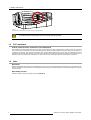
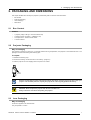
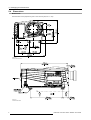


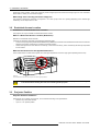


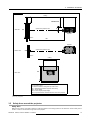

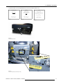
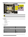
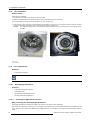
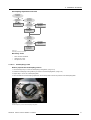
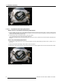


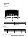
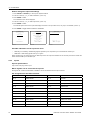
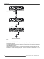
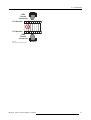
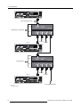
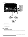
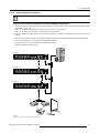
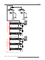

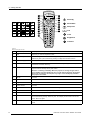
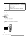
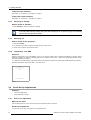

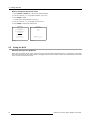
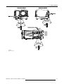
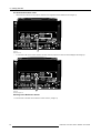

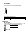
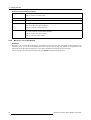

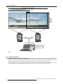


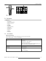
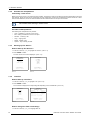
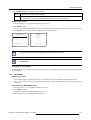
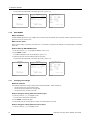


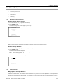

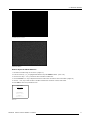


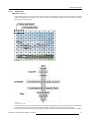
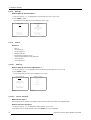
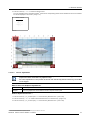


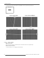
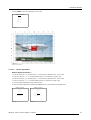
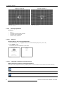
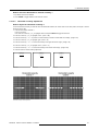


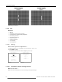


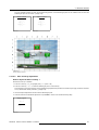

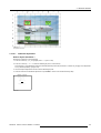
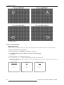


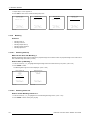
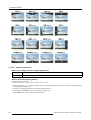


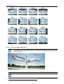
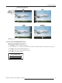


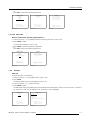

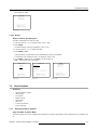


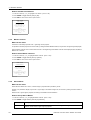
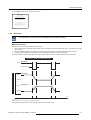
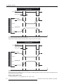

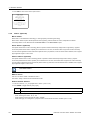


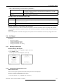
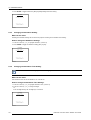
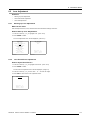
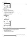


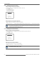
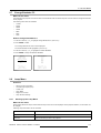
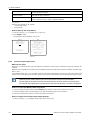
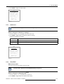

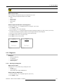
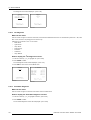

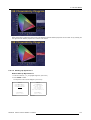

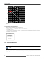
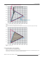
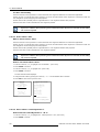

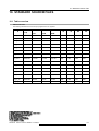


![SLM R12+ Performer [v05]](http://vs1.manualzilla.com/store/data/006791929_1-ebbedd3225f10ee802ba80a2e30391d2-150x150.png)
![SLM R12+ Performer [v05]](http://vs1.manualzilla.com/store/data/006296879_1-50504fc86d9979ae79ec928acfe3e08c-150x150.png)