1
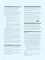
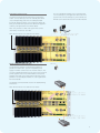
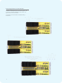
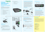
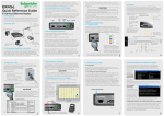
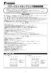
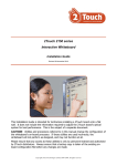
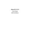
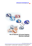
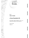
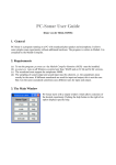
E Series Data Radio – EH450 Quick Start Guide
Quick Start Guide EH450
Hot Standby Base Station
Introduction
Welcome to the Quick Start Guide for the EH450
Hot Standby Base / Repeater Data Radio. This section
provides additional step-by-step instructions to install,
commission and operate the EH450 Hot Standby Base
Station. This document should be read in conjunction
with the EB450 Base Station Quick Start Guide.
The EH450 is a fully redundant, hot standby digital
data radio base / repeater station providing automatic
changeover facilities.
The EH450 is designed as a modular solution,
comprising 2 identical EB450 base station units
(standard) linked to a central, fail-safe monitoring
and changeover controller (Hot Standby Controller).
Either base station may be taken out for maintenance
without the need for any system down time. The
automatic changeover is triggered by out of tolerance
(alarm) conditions based on either RF and/or user data
throughput parameters.
Features and Benefits
•
Individual and identical base stations with separate
control logic changeover panel
•
Modules are hot swapable without user downtime
•
Flexible antenna options – single, separate Tx & Rx,
two Tx and two Rx
•
Increased sensitivity with receiver pre-amplifier
•
Both on-line and off-line units monitored
regardless of active status
•
Also refer to the common Features and Benefits
list of the E Series Data Radio
Base / Repeater Unit
Hot Standby Controller Unit
Base / Repeater Unit
Note: RF Connectors not used for ETSI Version
Rear View
1
E Series Data Radio – EH450 Quick Start Guide
Operational Description
Mounting and Environmental Considerations
The Hot Standby Controller (HSC) unit is a 1RU rack
mounted module that interfaces to two physically
separate base stations (each 2RU rack mounted
modules) via a number of RF and data cables.
The EH450 Hot Standby Base Station is housed as a
5RU 19” rack mounted set, encompassing 2 x 2RU Base
Station units and 1 x 1RU Hot Standby Controller unit. The mounting holes on the front panels should be used to
secure the units to the rack.
Both base stations are operating simultaneously and
both units are constantly receiving signals, however only
data from one base station, the “online” base station is
directed to the user equipment. The online base station
is the only base station transmitting at any time. The Hot
Standby Controller has the following functions:
•
Diplex the transmit and receive paths (Assuming
internal duplexer fitted) Tx only.
•
Amplify and split the incoming signal two ways so
both base stations receive at once.
•
Monitor status reports from both base stations
to identify faults and swap over the online base
station if required.
•
Switch the antenna via internal coaxial relay
duplexer to the online base station transmitter and
inhibit the offline base station from transmitting.
•
Switch the User A and B data ports through to the
online base station.
An optocoupler based switch in the base station
controller directs data to and from ports A and B on the
rear panel directly to ports A and B on the on-line base
station without any involvement from the Hot Standby
controller microcontrollers (apart from selecting the online base). This provides protection of the system from
failure of the microcontroller.
As well as ports A and B, each base has a system port.
The system port of each base station is interfaced to
the microcontroller on the Hot Standby controller. This
allows the microcontroller in charge of selecting the base
station to receive diagnostic messages from each base
station to decide their health.
The base station has it’s own system port on the rear
panel and this is interfaced to the Hot Standby Controller
Module. The HSC will route diagnostics at the rear panel
system port to and from the system ports of the base
stations.
Warning - RF Exposure
The radio equipment described in this user manual emits
low level radio frequency energy. The concentrated
energy may pose a health hazard depending on the type
of antenna used. In the case of:
Non-directional antenna - DO NOT allow people to come
within 0.5 metres (20 inches) of the antenna when the
transmitter is operating
Directional antenna - DO NOT allow people to come
within 6 metres (20 feet) of the antenna when the
transmitter is operating.
22
The unit should be mounted in a clean and dry location,
protected from water, excessive dust, corrosive fumes,
extremes of temperature and direct sunlight. Please allow
sufficient passive or active ventilation to allow the base
stations heatsink to operate efficiently.
All permanent connections are made at the rear of the
unit. This includes: Power, Antenna, Communications
Ports, Digital I/O and System Port. The front panel has an
additional System Port connection point for easy access.
The Base Station front panel system ports must not be
used while in this Hot Standby configuration.
Warning - System Port Priority
The base station front panel system port has priority over
the rear panel port, which is used for communication
between the base station and the Hot Standby Controller.
This is to permit service personnel to reconfigure the base
station module without disconnection from the Hot Standby
Controller. It should be noted however, that when the front
panel port is accessed, a changeover event will occur due to
lost communications with the Hot Standby Controller.
Compliance Information
FCC Notice
This equipment has been tested and found to comply
with the limits for a Class B digital device, pursuant to Part
15 of the FCC Rules. These limits are designed to provide
reasonable protection against harmful interference in a
residential installation. This equipment generates, uses,
and can radiate radio frequency energy and, if not installed
and used in accordance with the instruction, equipment
may cause harmful interference to radio communications.
However, there is no guarantee that interference will not
occur in a particular installation. If this equipment does
cause harmful interference to radio or television reception,
which can be determined by turning the equipment
off and on, the user is encouraged to try to correct the
interference by one or more of the following measures:
•
Re-orient to relocate the receiving antenna.
•
Increase the separation between the equipment and
receiver.
•
Connect the equipment into an outlet on a circuit
different to that which the receiver is connected.
•
Consult the dealer or an experienced radio/television
technician for assistance.
IC Notice
This Class B digital apparatus complies with Canadian
ICES-003.
Cet appariel numerique de la class B est conforme a la
norme NBM-003 du Canada.
E Series Data Radio – EH450 Quick Start Guide
Communications Ports
The A & B Data Ports and System Ports of each Base
Station connect directly to the Hot Standby Controller
units corresponding ports with the cables provided.
Ensure all clamping screws on the Data Port cables are
firmly secured and the System Port cables are clipped in
correctly. See figure below for further details.
The Hot Standby Controller units A & B Data Ports
connect directly to your application device and the
System Port connects directly to your local PC. See
ER450 Quick Start Guide Section for further details.
Note: Only the front or rear user System Port can be
used at any one time on the HSC.
Note: RF Connectors not used for ETSI version
Power Supply and Protection
The EH450 has facilities for dual power supplies to
provide for a redundant system. A separate power
supply should be used for each of the Base Station units.
The Hot Standby Controller unit has connections for dual
power supplies and it is recommended that the power
supplies from each of the Base Stations also be used to
power the Hot Standby Controller unit. See Figure below
for further details.
See ER450 Quick Start Guide Section for detailed wiring
information.
Note: RF Connectors not used for ETSI version
3 3
E Series Data Radio – EH450 Quick Start Guide
Connecting Antennas and RF Feeders
There are 3 primary antenna connection options. All
connectors used are standard N Type sockets. See
figures below for further details.
See ER450 Quick Start Guide for detailed wiring
information.
44
E Series Data Radio – EH450 Quick Start Guide
Front Panel Operation
Switches
System Port
Select Switch
There are two system port connection points, one on
the rear panel and one on the front panel. Both have the
same functionality and can be used for local diagnostics,
firmware front panel downloads and hot standby
controller testing. To access the system port use the
diagnostic/programming cable supplied.
The 3 position switch (1 / Auto / 2) on the front panel
provides the following functionality:
•
Position 1: base station 1 is forced into operation
•
Position Auto: changeover hardware will select the
on-line base station
•
Position 2: base station 2 is forced into operation
The select switch is also used to identify the target base
station for configuration programming.
Note: When connection is made to front panel system
port, rear system port is disabled.
Alarm Status LEDs
Select LEDs
There are 10 alarm LEDs on the front panel, five for
base 1 and five for base 2. These LEDs provide a
general indication of base station status. More detailed
base station status information is available by using the
diagnostic utility software.
•
Green - Auto Mode
The indicated alarms for each base station are:
•
Red - Remote Force
Freq.
=>
Frequency Error
•
Amber - Local Force
RxSig
=>
Receive Signal (RF) Error
2 Green Firmware Download Mode
Data
=>
Receive Data Error
2 Amber Test Mode
TxPower
=>
Transmit Power (RF) Error
2 Red Fatal Error - refer user manual
Supply
=>
DC Voltage Error
Reset Switch
The status of each alarm is represented as follows:
Adjacent to the select switch are two LEDs: These LEDs
indicate the current active base station.
This is a momentary close switch which when depressed
will reset all LED alarm indications.
Off
=>
Unknown
Green
=>
No Error
Red
condition
=>
Current (active) Error
=>
Recovered Error condition
Amber
Any active or recovered error LEDs will turn to green
after the reset alarms switch has been pushed or
remotely reset.
5 5
E Series Data Radio – EH450 Quick Start Guide
E-mail Technical Support
When e-mailing questions to our support staff, make
sure you tell us the exact model number (and serial
number if possible) of the Trio equipment you are
working with. Include as much detail as possible about
the situation, and any tests that you have done which
may help us to better understand the issue. If possible,
please include your telephone contact information
should we wish to further clarify any issues.
Contact Details
Technical Support: Europe, Africa, Middle East
Available: Monday to Friday 8:30am - 5:30pm
Central Europe Standard Time
Direct Worldwide: +31 (71) 579 1655
Email: [email protected]
Technical Support: The Americas
Available: Monday to Friday 8:00am - 6:30pm
Eastern Standard Time
Toll free within North America: 1-888-226-6876
Direct Worldwide: +1 (613) 591-1943
Email: [email protected]
Technical Support: Asia Pacific
Available: Monday to Friday 8:30am - 5:30pm
Australian Eastern Standard Time
Direct Worldwide: +61 3 8773 0100 Email: [email protected]
Information subject to change without notice.
© Copyright 2011Trio Datacom Pty Ltd. All rights reserved.
Issue: 06-11
6 6