1
E-Series Ethernet
Radio User Manual
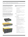
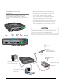
ER45e Remote Data Radio
EB45e Base Station
EH45e Hot Standby Base Station
Firmware version 5.5.0
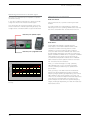
ER45e Remote Data Radio
EB45e Base Station
EH45e Hot Standby Base Station
1
Contents
Part A – Preface
3
Warranty3
Important Notice
3
Related Products
3
Other Related Documentation and Products
3
Revision History
3
Compliance Information 4
Safety4
Site Earthing
4
Safety Information
5
Part B – Ethernet E Series Overview
6
Definition of Ethernet E Series Radio
6
Ethernet E Series Product Range
6
Features6
Build Matrix
8
Part C – Network Types
12
Introduction Point-to-Point Networks (PTP)
Point-to-Multipoint Networks (PTMP)
Digipeater Systems
12
12
13
14
Part D – Features
15
Ethernet Features
15
SNMP Diagnostics
16
SNMP Notifications
16
Network Management and Remote Diagnostics 17
eDiags18
eConfig 19
Hot Standby Redundant Ethernet Connections 21
Ethernet Link Monitoring
21
Hot Standby Controller Shared IP
21
Terminal Servers
22
MODBUS gateway 25
Connectivity27
Radio and Modem Features
28
Security28
Part E – Getting Started
29
Understanding RF Path Requirements
29
Examples of Predictive Path Modelling
29
Power Supply and Environmental Considerations
33
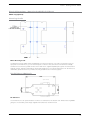
Physical Dimensions - Remote Data Radio - ER45e 34
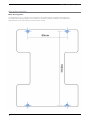
Physical Dimensions - Mounting Cradle/Din Rail Mount35
Mounting Cradle
35
Din Rail Mount (Optional)
35
Hole drilling template
36
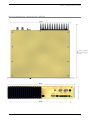
Physical Dimensions - Base Station - EB45e
37
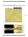
Physical Dimensions - Hot Standby Base - EH45e
38
ER45e Quick Start Guide
39
EB45e Quick Start Guide
46
EH45e Quick Start Guide
49
2
Part F – Quick Reference Guide
54
SNMP eDiags - Configuration
54
63
Part G – Commissioning & Maintenance
64
Power-up64
LED Indicators
64
Data Transfer Indications
64
Antenna Alignment and RSSI Testing
64
Link Establishment and BER Testing
64
VSWR Testing
64
Testing Ethernet Connectivity
65
Routine Maintenance Considerations
66
Ethernet E-Series Error LED indications
66
Part H – TView+ Management Suite Programmer67
Introduction67
Installation67
Programmer68
TView+ Front Panel
68
Part I – Appendices
85
Appendix A - Firmware Updates
85
Appendix B: Open Source License Acknowledgements90
Part J – Support Options
93
E-mail Technical Support
93
Part A - Preface
Part A – Preface
Warranty
Important Notice
All equipment supplied by Trio Datacom Pty Ltd (As
of 1 January 2009) is covered by warranty for faulty
workmanship and parts for a period of three (3) years
from the date of delivery to the customer. During
the warranty period Trio Datacom Pty Ltd shall, at its
option, repair or replace faulty parts or equipment
provided the fault has not been caused by misuse,
accident, deliberate damage, abnormal atmosphere,
liquid immersion or lightning discharge; or where
attempts have been made by unauthorised persons to
repair or modify the equipment.
© Copyright 2012 Trio Datacom Pty Ltd All Rights
Reserved
The warranty does not cover modifications to
software. All equipment for repair under warranty
must be returned freight paid to Trio Datacom Pty
Ltd or to such other place as Trio Datacom Pty Ltd
shall nominate. Following repair or replacement the
equipment shall be returned to the customer freight
forward. If it is not possible due to the nature of the
equipment for it to be returned to Trio Datacom Pty
Ltd, then such expenses as may be incurred by Trio
Datacom Pty Ltd in servicing the equipment in situ shall
be chargeable to the customer.
When equipment for repair does not qualify for
repair or replacement under warranty, repairs shall
be performed at the prevailing costs for parts and
labour. Under no circumstances shall Trio Datacom Pty
Ltd’s liability extend beyond the above nor shall Trio
Datacom Pty Ltd, its principals, servants or agents be
liable for the consequential damages caused by the
failure or malfunction of any equipment.
Related Products
ER45e Remote Data Radio
EB45e Base/Repeater Station
EH45e Hot Standby Base Station
This manual covers the operation of the E Series Ethernet
Radios. Specifications described are typical only and are
subject to normal manufacturing and service tolerances.
Trio Datacom Pty Ltd reserves the right to modify the
equipment, its specification or this manual without prior
notice, in the interest of improving performance, reliability
or servicing. At the time of publication all data is correct
for the operation of the equipment at the voltage and/
or temperature referred to. Performance data indicates
typical values related to the particular product.
This manual is copyright by Trio Datacom Pty Ltd. All
rights reserved. No part of the documentation or the
information supplied may be divulged to any third party
without the express written permission of Trio Datacom
Pty Ltd.
Same are proprietary to Trio Datacom Pty Ltd and
are supplied for the purposes referred to in the
accompanying documentation and must not be used
for any other purpose. All such information remains
the property of Trio Datacom Pty Ltd and may not be
reproduced, copied, stored on or transferred to any other
media or used or distributed in any way save for the
express purposes for which it is supplied.
Products offered may contain software which is
proprietary to Trio Datacom Pty Ltd. However, the offer of
supply of these products and services does not include
or infer any transfer of ownership of such proprietary
information and as such reproduction or reuse without
the express permission in writing from Trio Datacom
Pty Ltd is forbidden. Permission may be applied for by
contacting Trio Datacom Pty Ltd in writing.
Other Related Documentation and
Products
ER45e Quick Start Guide
TView+ Management Suite
Multiplexer Stream Router (MSR)
Revision History
Issue 10-12 (October 2012) - Added details for new
features available in firmware 5.5.0.
3
Part A - Preface
Compliance Information
Warning - RF Exposure
The radio equipment described in this user manual emits
low level radio frequency energy. The concentrated
energy may pose a health hazard depending on the type
of antenna used.
To satisfy EU and FCC requirements a minimum
separation distance should be maintained between the
antenna of this device and persons during operation as
per the table below.
Site Earthing
Ensure that the chassis mounting plate, power supply
(-) earth, RTU terminal device, and lightning arrester,
are all securely connected to the earth in the building
installation or a common ground point to which an earth
stake is attached.
R&TTE Notice (Europe)
Applies to models Ex45e-xxExx-xxx
In order to comply with the R&TTE (Radio &
Telecommunications Terminal Equipment) directive
1999/5/EC Article 3 (Low Voltage Directive 73/23/EEC),
all radio modem installations must include an external inline lightning arrestor or equivalent device that complies
with the following specifications:
• DC Blocking Capability - 1.5kV impulse (Rise
Time 10mS, Fall Time 700mS) (Repetition
10 Times) or 1.0kV rms 50Hz sine wave for 1
minute.
FCC Notice (Hot Standby Controller Only)
This equipment has been tested and found to comply
with the limits for a Class B digital device, pursuant to
Part 15 of the FCC Rules. These limits are designed
to provide reasonable protection against harmful
interference in a residential installation. This equipment
generates, uses, and can radiate radio frequency energy
and, if not installed and used in accordance with the
instruction, equipment may cause harmful interference
to radio communications. However, there is no
guarantee that interference will not occur in a particular
installation. If this equipment does cause harmful
interference to radio or television reception, which can
be determined by turning the equipment off and on, the
user is encouraged to try to correct the interference by
one or more of the following measures:
• Re-orient to relocate the receiving antenna.
• Increase the separation between the equipment
and receiver.
• Connect the equipment into an outlet on a
circuit different to that which the receiver is
connected.
• Consult the dealer or an experienced radio/
television technician for assistance.
IC Notice (Hot Standby Controller Only)
This Class B digital apparatus complies with Canadian
ICES-003. Cet appariel numerique de la class B est
conforme a la norme NBM-003 du Canada.
Safety
Warning: Where an ER45e is to be operated between
45°C and 70°C ambient, it must be installed in a
restricted access location.
Warning: Where an EB45e is to be operated between
50ºC and 70ºC, it must be installed in a restricted
access location.
4
Trio Datacom declares that the Ethernet E-Series radio
modem range are in compliance with the essential
requirements and other relevant provisions of the
Directive 1999/5/EC. Therefore Trio Datacom Ethernet
E-Series equipment is labelled with the following CEmarking.
0889
Co-Locating the ER45e remote (Europe)
The ER45E is a remote radio and should not be colocated with other transmitting equipment.
Part A - Preface
Safety Information
Read these instructions carefully, and look at the
equipment to become familiar with the device
before trying to install, operate, or maintain it.
The following special messages may appear
throughout this documentation or on the
equipment to warn of potential hazards or to call
attention to information that clarifies or simplifies
a procedure.
The addition of this symbol to a Danger or
Warning safety label indicates that an electrical
hazard exists, which will result in personal injury
if the instructions are not followed.
This is the safety alert symbol. It is used to
alert you to a potential personal injury hazards.
Obey all safety messages that follow this
symbol to avoid possible injury or death.
WARNING indicates a poentialy hazardous situation which, if not
avoided, can result in death or serious injury.
CAUTION indicates a potentially haradous situation which, if not
avoided, can result in minor or moderate injury.
CAUTION, used without the safety alert symbol, indicates a
potentially hazardous situation which, if not avoided, can result in
equipment damage.
WEEE Notice (Europe)
This symbol on the product or its packaging indicates
that this product must not be disposed of with other
waste. Instead, it is your responsibility to dispose of your
waste equipment by handing it over to a designated
collection point for the recycling of waste electrical
and electronic equipment. The separate collection
and recycling of your waste equipment at the time of
disposal will help conserve natural resources and ensure
that it is recycled in a manner that protects human
health and the environment. For more information
about where you can drop off your waste equipment
for recycling, please contact the dealer from whom you
originally purchased the product.
Dieses Symbol auf dem Produkt oder seinem Verpacken
zeigt an, daß dieses Produkt nicht mit anderer
Vergeudung entledigt werden darf. Stattdessen ist
es Ihre Verantwortlichkeit, sich Ihre überschüssige
Ausrüstung zu entledigen, indem es rüber sie zu
einem gekennzeichneten Ansammlungspunkt für
die Abfallverwertung elektrische und elektronische
Ausrüstung übergibt. Die unterschiedliche Ansammlung
und die Wiederverwertung Ihrer überschüssigen
Ausrüstung zu der Zeit der Beseitigung helfen,
Naturresourcen zu konservieren und sicherzugehen, daß
es in gewissem Sinne aufbereitet wird, daß menschliche
Gesundheit und das Klima schützt. Zu mehr Information
ungefähr, wo Sie weg von Ihrer überschüssigen
Ausrüstung für die Wiederverwertung fallen können,
treten Sie bitte mit dem Händler in Verbindung, von dem
Sie ursprünglich das Produkt kauften.
PLEASE NOTE
Electrical equipment should be installed, operated,
serviced, and maintained only by qualified
personnel. No responsibility is assumed by
Schneider Electric for any consequences arising
out of the use of this material.
5
Part B – E Series Overview
Part B – Ethernet E Series Overview
Definition of Ethernet E Series Radio
The E Series Ethernet radios are a range of wireless
modems designed for the transmission of data/
Ethernet communications for SCADA, telemetry and any
other information and control applications that utilise
ASCII messaging techniques. The E Series Ethernet
radios use advanced “digital” modulation and signal
processing techniques to achieve exceptionally high data
throughput efficiency using traditional licensed narrow
band radio channels.
These products are available in many frequency band
and regulatory formats, to suit spectrum bandplans, in
various continental regions. The range is designed for
both fixed point to point (PTP), and multiple address
(MAS) or point to multipoint (PTMP) systems.
Ethernet E Series Product Range
The E Series Ethernet product range consists of the
basic half duplex “Remote” radio modem, an extended
feature full duplex Remote radio modem, and ruggedised
Base Station variants, including an optional Hot
Standby controller to control two base station units in a
redundant configuration.
Features
Ethernet
• Maximum narrowband channel utilization with
• Smart peer to peer repeating
• Ethernet filtering
• Data Compression
• Flexible system configuration using IP Layer 3
transport & routing
• Advanced commissioning tools and remote
diagnostics including SNMP.
• RS-232 serial support via embedded terminal
server (UDP/TCP).
Security
• Secure operation with 128-bit AES encryption**
• Password protected remote configuration
including SNMP
Radio and Modem
• Up to 19,200 bps over-air data rates in 12.5 &
25kHz channels
• ChannelShare™ unique integrated C/DSMA
collision avoidance technology permits
simultaneous polling and spontaneous alarm
reporting operation in the same system.
• Improved scan times with fast data turnaround
ER45e Remote Radio
• Simplex, Half Duplex and Full Duplex (Full Duplex
with ERFD450 option)
• Reliable operation from -30o to + 70o C
• High performance transmitter with
overtemperature and high VSWR protection
• DIN Rail mounting kit option
Connectivity
EB45e Base / Repeater Station
• Independent Ethernet & Serial ports
• Compatible with most SCADA protocols:
Ethernet/IP & Serial (MODBUS / DNP-3 / IEC etc)
• Ethernet Port is 10/100Mbps (auto MDIX
sensing) IEEE 802.3
• Selectable 300 - 38.4 kbps asynchronous RS232 interface
• RS-232 serial support via embedded terminal
server (UDP/TCP).
• Separate on-line system port avoids the need to
interrupt user data for configuration access
EH45e Hot Standby Base Station
6
Part B – E Series Overview
Network Management and Remote Diagnostics
• Remote fully transparent Network Management
and Diagnostics
• Network wide operation from any radio modem
• Full SCADA style features such as database,
trending and networking
• Over-the-air modem reconfiguration
• Full graphical presentation (HMI)
• Note: Some features require TView+ software
• Radio is SNMP V1/V2c RFC-1213 compliant
and supports Trio E-Series radio diagnostics
parameters (including alarm generation via
traps).
7
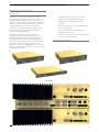
Part B – E Series Overview
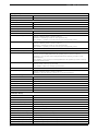
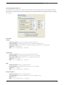
Build Matrix
Product Data Sheet Trio ER45e | ER450 Model Code
TBURER45x-aabbbcde represents the part number matrix
Model
Trio Radio ER450 & ER45e
TBURE
E-Series
Code
R
Code
45
Code
Select: Unit Type
Remote Station with full enclosure
Select: Generic Frequency Band
370 to 518 MHz
Select: Data Ports
0
Two serial ports
E
One Ethernet & one serial port
Code
Frequency (400MHz bands) – Frequencies to be specified at time of order
46
370 to 388 MHz (Tx & Rx)
47
380 to 396 MHz (Tx & Rx)
48
395 to 406 MHz (Tx & Rx)
50
403 to 417 MHz (Tx & Rx)
63
406 to 421 MHz (Tx & Rx)
64
415 to 430 MHz (Tx & Rx)
56
418 to 435 MHz (Tx & Rx)
57
428 to 444 MHz (Tx & Rx)
55
436 to 450 MHz (Tx & Rx)
51
450 to 465 MHz (Tx & Rx)
65
455 to 470 MHz (Tx & Rx)
52
465 to 480 MHz (Tx & Rx)
53
480 to 494 MHz (Tx & Rx)
60
490 to 500 MHz (Tx & Rx)
54
505 to 518 MHz (Tx & Rx)
A6
370 to 400 MHz (Tx & Rx)
B3
395 to 426 MHz (Tx & Rx)
B4
413 to 447 MHz (Tx & Rx)
B5
433 to 450 MHz (Tx & Rx)
C1
436 to 467 MHz (Tx & Rx)
C2
450 to 487 MHz (Tx & Rx)
C3
473 to 518 MHz (Tx & Rx)
Code
Select: RF Channel Data Rate & Bandwidth (Internal Modem)
F01
FCC (IC) 9600 / 19k2bps, 12.5kHz – provides M-Series 003 compatability
F02
FCC (IC) 19k2bps, 25kHz – Not for sale in North America
E01
ETSI 9600bps, 12.5kHz – provides M-Series 004 compatability
A01
ACMA 4800 / 9600bps, 12.5kHz – provides M-Series 001/002 compatability
A02
ACMA 9600 / 19K2bps, 25kHz
Code
Select: Encryption (subject to country of use)
D
No Encryption
X
No Encryption, full duplex option - requires external duplexer
E
Encryption*
Y
Encryption*, full duplex option - requires external duplexer
Code
H
Code
0
Select: Hazardous Area Approvals
Hazardous Environment Class 1 Div 2 Groups A, B, C & D
Hot Standby Configuration
Not used
Example: TBURER450-A6F01EH0 specifies: Trio ER450
remote station, two serial ports, frequencies to be
specified at time of order, FCC (IC) 12.5kHz, Encryption,
Class 1 Div 2. Export restrictions may apply. Contact
your local representative for more details.
* Export restrictions may apply. Contact your local
representative for more details.
8
Communications Standard:
FCC- Federal Communications Commission (USA)
IC- Industry Canada
ETSI - European Telecommunication Standards Institute
ACMA - Australian Communications and Media Authoroity
Part B – E Series Overview
Product Data Sheet Trio EB450 & EB45e Model Code
EB45x-aabbb-cde represents the part number matrix
Model
Trio Radio EB450 & EB45e
TBURE
E-Series
Code
Select: Unit Type
B
Code
45
Code
0
E
Code
Base / Repeater Station
Select: Generic Frequency Band
380 to 518 MHz
Select: Data Ports
Two serial ports
One Ethernet & one serial port
Frequency (400MHz bands) – Frequencies to be specified at time of order
47
380 to 396 MHz (Tx & Rx)
48
395 to 406 MHz (Tx & Rx)
50
403 to 417 MHz (Tx & Rx)
63
406 to 421 MHz (Tx & Rx)
64
415 to 430 MHz (Tx & Rx)
56
418 to 435 MHz (Tx & Rx)
57
428 to 444 MHz (Tx & Rx)
55
436 to 450 MHz (Tx & Rx)
51
450 to 465 MHz (Tx & Rx)
65
455 to 470 MHz (Tx & Rx)
52
465 to 480 MHz (Tx & Rx)
53
480 to 494 MHz (Tx & Rx)
60
490 to 500 MHz (Tx & Rx)
54
505 to 518 MHz (Tx & Rx)
A6
370 to 400 MHz (Tx & Rx)
B3
395 to 426 MHz (Tx & Rx)
B4
413 to 447 MHz (Tx & Rx)
B5
433 to 450 MHz (Tx & Rx)
C1
436 to 467 MHz (Tx & Rx)
C2
450 to 487 MHz (Tx & Rx)
C3
473 to 518 MHz (Tx & Rx)
Code
Select: RF Channel Data Rate & Bandwidth (Internal Modem)
F01
FCC (IC) 9600 / 19k2bps, 12.5kHz – provides M-Series 003 compatability
F02
FCC (IC) 19k2bps, 25kHz – Not for sale in North America
E01
ETSI 9600bps, 12.5kHz – provides M-Series 004 compatability
A01
ACMA 4800 / 9600bps, 12.5kHz – provides M-Series 001/002 compatability
A02
ACMA 9600 / 19K2bps, 25kHz
Code
Select: Diagnostics & Encryption
D
Diagnostics Only (No Encryption)
E
Diagnostics & Encryption*
Code
Select: Options
0
Separate Tx & Rx Antenna Ports
1
Configured for internal band reject duplexer. Duplexer not included. Contact local sales office for further details.
A
Code
0
20W RF Power Output**
Hot Standby Configuration
Not used
Example: TBURER450-A6F01EH0 specifies: Trio ER450
remote station, two serial ports, frequencies to be
specified at time of order, FCC (IC) 12.5kHz, Encryption,
Class 1 Div 2. Export restrictions may apply. Contact
your local representative for more details.
* Export restrictions may apply. Contact your local
representative for more details.
** Local regulatory conditions may prevent the use of
20W in some countries.
Communications Standard:
FCC- Federal Communications Commission (USA)
IC- Industry Canada
ETSI - European Telecommunication Standards Institute
ACMA - Australian Communications and Media Authoroity
9
Product Data Sheet Trio EH450 & EH45e Model Code
Part B – E Series Overview
EH45x-aabbb-cde represents the part number matrix
Model
Trio Radio EH450 & EH45e
TBURE
E-Series
Code
Select: Unit Type
H
Code
45
Code
Hot Standby Base / Repeater
Select: Generic Frequency Band
380 to 518 MHz
Select: Data Ports
0
Two serial ports
E
One Ethernet & one serial port
Code
Frequency (400MHz bands) – Frequencies to be specified at time of order
47
380 to 396 MHz (Tx & Rx)
48
395 to 406 MHz (Tx & Rx)
50
403 to 417 MHz (Tx & Rx)
63
406 to 421 MHz (Tx & Rx)
64
415 to 430 MHz (Tx & Rx)
56
418 to 435 MHz (Tx & Rx)
57
428 to 444 MHz (Tx & Rx)
55
436 to 450 MHz (Tx & Rx)
51
450 to 465 MHz (Tx & Rx)
65
455 to 470 MHz (Tx & Rx)
52
465 to 480 MHz (Tx & Rx)
53
480 to 494 MHz (Tx & Rx)
60
490 to 500 MHz (Tx & Rx)
54
505 to 518 MHz (Tx & Rx)
A6
370 to 400 MHz (Tx & Rx)
B3
395 to 426 MHz (Tx & Rx)
B4
413 to 447 MHz (Tx & Rx)
B5
433 to 450 MHz (Tx & Rx)
C1
436 to 467 MHz (Tx & Rx)
C2
450 to 487 MHz (Tx & Rx)
C3
Code
473 to 518 MHz (Tx & Rx)
Select: RF Channel Data Rate & Bandwidth (Internal Modem)
F01
FCC (IC) 9600 / 19k2bps, 12.5kHz – provides M-Series compatability
F02
FCC (IC) 19k2bps, 25kHz – Not for sale in North America
E01
ETSI 9600bps, 12.5kHz
A01
ACMA 4800 / 9600bps, 12.5kHz - provides M-Series compatability
A02
Code
D
E
Code
ACMA 9600 / 19k2bps, 25kHz
Select: Diagnostics & Encryption
Diagnostics Only (No Encryption)
Diagnostics & Encryption*
Select: Options
0
Separate Tx & Rx Antenna Ports
1
Internal base station band reject duplexers. No RF switching via Hot Standby Controller. Ref to Hot Standby configuration diagram. #
A
20W RF Power Output**
Code
Hot Standby Configuration
A
Separate Tx & Rx Antenna ports with RF switching via Hot Standby Controller
B
Dual Redundant External Duplexers (not included) with no RF switching via Hot Standby Controller
C
Internal hot standby controller band reject duplexers. No RF switching via Hot Standby Controller. Ref to Hot Standby configuration diagram. #
Example: TBUREH450-C2F01E0A specifies: Trio EH450
hotstandby repeater, two serial ports, frequencies to
be specified at time of order, FCC (IC) 9600/19K2bps,
12.5kHz, Diagnostics & Encryption, seperate Rx & Tx ports.
*Export restrictions may apply. Contact your local sales
office for details.
**Local regulatory conditions may prevent the use of 20W
in some countries.
10
#Note - Suitable duplex reference number is
TBURDUPLXBR450COD. The supply of duplexers is not
included in the reference number or in the price for any
reference number - the reference number only indicates
that equipment is configured for a particular duplexer
arrangement. If TBURDUPLXBR450COD duplexer is required
to be factory fitted then this must be clearly specified at time
of order. Contact local sales office for further details.
Part B – E Series Overview
EH45x Hot Standby Controller Configurations
EHHSC Hot Standby Controller Version
External Duplexer
TBUREH45x-xxxxxxxA
• 2 x TBUREB45-xxxxxxxx0
• 1 x TBUREHHSC-00A
TBUREH45x-xxxxxxxB
• 2 x TBUREB45x-xxxxxxx0
• 1 x TBUREHHSC-00B
Internal Duplexer (Band Reject only)
TBUREH45x-xxxxxx0C
• 2 x TBUREB45x-xxxxxx00
• 1 x TBUREHHSC-00C
– duplexer insider EHHSC*
TBUREH45x-xxxxxx1B
• 2 x TBUREB45x-xxxxxx10
– duplexer insider EB45x*
• 1 x TBUREHHSC-00B
– standard option B as above
EB45x
A
EB45x
EB45x
B
EB45x
EB45x
C
EB45x
EB45x
B
EB45x
Hot Standby Controller options
Description
Duplexer
Antenna Type
A
LNA & RF Relay
Fitted
Not Fitted
Separate
Tx & Rx Ant
B
No RF
connections
Not Fitted
No Antenna
C
LNA & RF Relay
Fitted
Band
Reject
Connection
Single
Antenna
(Tx/Rx)
#Note – Suitable duplexer reference number is
TBURDUPLXBR450COD. The supply of duplexers is
not included in the reference number or in the price
for any reference number – the reference number only
indicates that equipment is configured for a particular
duplexer arrangement. If TBURDUPLXBR450COD
duplexer is required to be factory fitted then this must
be clearly specified at time of order.
Contact local sales office for further details.
LNA (Low Noise Receiver Amplifier / Splitter)
RELAY (Coaxial Transmitter Switch)
DUPLEXER
11
Part C – Applications
Part C – Network Types
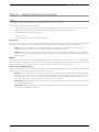
Introduction
Fundamental to understanding the use of E Series Ethernet Radios in your system is the need for a basic understanding
of the different types of radio network topologies (known as NETWORK TYPES) and the function of each radio within them
(known as RADIO MODES).
The following table provides a brief overview of each:
Network Types:
Point to Point (PTP): One Access Point radio is configured to communicate with a REMOTE radio in PTP mode.
Point to Multipoint (PTMP): One Access Point radio is configured to communicate with multiple REMOTE radio(s) a PTMP network
Multipoint to Multi point simplex frequency(MPMP): All units configured as Access Point with Carrier Detect Collision
Avoidance remote set in all.
Radio Modes:
Access Point: Defines the Access Point radio in a network. The function of the Access Point is to manage remotes or
access points.
Remote: A remote radio in the network. The function of a remote is to communicate with the Access Point either directly
or if it is the repeater, then through it.
Each type of network is described in the following diagrams.
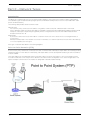
Point-to-Point Networks (PTP)
A Point to Point (PTP) network has one Access Point and one remote radio. Normally full duplex radios are installed, providing
full data throughput in each direction. Alternatively, half-duplex radios can also be implemented although collision avoidance
must be enabled.
Full Duplex radios have the advantage that they simulate a cable connection with respect to the connected device. Even
if one device transmits continuously it will not block the other device from sending data. This is useful for applications that
expect full duplex communications or that are not designated to be radio modem friendly.
12
Part C – Applications
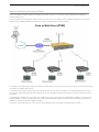
Point-to-Multipoint Networks (PTMP)
A Point to Multipoint (PTMP) network is normally chosen when one site (i.e.: The HOST) needs to broadcast messages to
multiple REMOTE sites.
Point to Multipoint (PTMP) operation requires the Access Point site to have adequate RF coverage of all Remote sites. A PTMP
offers the best available bandwidth and data latency when multiple remote sites are required.
Point to Multi-Point (PTMP)
In a multiple access radio system (MAS),user data is broadcast from one common site (the Access Point) to all others, either using
a half duplex or simplex radio channel.
To facilitate efficient data communication and support features such as collision avoidance, it is recommended that the Access
Point be a full duplex radio. Utilizing a half duplex access point is possible, however system restrictions and RF collissions must be
considered.
For serial data, the SCADA host must support an addressing system such as a DNP or MODBUS device address, since the Access
Point broadcasts this data to all remotes. Ethernet data is transported transparently and end devices will identify information for
themselves using the Ethernet/IP header information.
This type of system topology is the most efficient PTMP topology and should always be implemented if possible.
13
Part C – Applications
Digipeater Systems
A Point to Multipoint via repeater network is a variation of the Point To Multipoint network. It is normally chosen when the
site where the SCADA (i.e.: Data) entry point does not have adequate RF coverage of other Remote sites in the network. The
network diagram is shown below.
In this network topology, the Access Point radio is configured as a Repeater. The repeater should be located at a site with
adequate RF coverage to each of the remotes. The Repeater still behaves as an Access Point to the Remotes as in a Point
to Multipoint network, but the Repeater is configured to repeat data messages between remotes in the network. It therefore
allows peer to peer communication to occur between remotes.
Because the Access Point radio now needs to “Repeat” data, data latency for messages from the Host Application to/from
the Remotes will be longer. However, the Repeater/Access Point is normally a full duplex device and this means it is capable
of receiving and transmitting repeated data simultaneously.
All other aspects of the Point to Multipoint network apply to this network topology.
Point to Multi-Point Via a Repeater (PTMP/R)
14
Part D – Features
Part D – Features
Ethernet Features
Smart peer to peer repeating
Smart peer to peer repeating improves the available bandwidth in systems where peer to peer connectivity is required. The filtering is
implemented within the Access Point of a PTMP system. Essentially, it prevents the unnecessary repeating of Ethernet traffic which is
inherently point to point in nature (i.e. a TCP session). When two remote radios need to communicate with each other (often referred
to as Peer to Peer), the Access Point will repeat the traffic to provide peer to peer connectivity. However, if the traffic is from a remote
to a device connected to an Access point, then peer to peer repeating is not required and the Access Point will not repeat the traffic.
The Access Point learns what devices (MAC addresses) require repeating. By learning where devices are located on the network, the
route table does not require any special configuration or setup. If a messages has a broadcast address and peer to peer is enabled,
the message will be repeated. If peer to peer connectivity is not required, it can be disabled to prevent the unnecessary repeating of
broadcast traffic.
Ethernet filtering
Ethernet filtering provides an easy to configure Layer 2 filtering mechanism, which can prevent unnecessary Ethernet traffic
increasing channel loading. There are various different addressing methodologies that can be filtered, which include:
Unicast:
Unicast is an addressing methodology that delivers messages to a single network destination
identified by a unique address.
Multicast:
Multicast is an addressing methodology that delivers messages to a group of destination addresses
simultaneously in a single transmission. Spanning tree messages are an example of multicast
messages.
Broadcast:
Broadcast is an addressing methodology that delivers messages to every device on a network. The
broadcast address of a device is calculated from the subnet mask. If all devices within a network use a
common network mask, the broadcast address will also be common.
Although typical SCADA applications only require Unicast & ARP data, the filtering mechanism provides the option to allow:
• All Ethernet traffic
• Unicast & ARP only (ARP is primarily used by networks to identify which physical devices own which IP addresses).
• Unicast only (Only used when a MAC address table is statically assigned).
• Or allow traffic from a single MAC address only.
Although Spanning tree messages are multicast messages, they are also filtered out unless the user is allowing all Ethernet
traffic to pass. This is also to prevent unnecessary channel loading.
Data Compression
Ethernet SCADA data is highly compressible due to continuous sequences of ones and zeros. Compression will minimise the
amount of RF channel loading by compressing all Ethernet data transmitted that is sent over the air. Compression is applied
to all Ethernet data which can significantly improveme data throughput and latency.
15
Part D – Features
SNMP Diagnostics
The Ethernet E-Series can provide SNMP diagnostic data via an internal SNMP agent. The radio supports SNMP v1 & v2c along with
notifications which includes traps and informs. SNMP facilities include RFC1213, Ethernet diagnostics and radio diagnostics
The features and benefits of SNMP diagnostics include:
• SNMP messages/notifications can be sent to Clear SCADA or SNMP management software.
• SNMP notifications provide real time alarm reporting.
• Eliminates the need for radio polling.
• Radios can send diagnostic information via SNMP periodically (diagnostics heartbeat).
Schneider Electric supply .MIB files that can be imported into most major SNMP Management consoles. These .MIB files
define the contents of the SNMP parameters including a description for each parameter. The parameters are sorted into six
distinct groups. The general group, the radio group, the security group, the lan group, the error group and the notification
group. More information on SNMP can be found in Part F of this user manual.
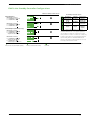
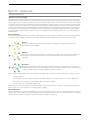
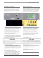
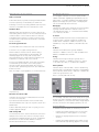
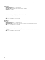
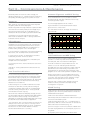
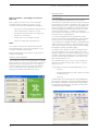
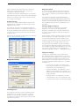
SNMP Notifications
As of Ethernet E-Series firmware version 5.5.0, the Ethernet E-Series has the capability to send SNMP notifications. An SNMP
notification is a message to inform a user that some sort of state of the radios has changed, these states include; input
voltage, temperature, Tx power, etc. There are two types of SNMP notifications available which are traps and informs.
• A trap is a single UDP message that is sent from the Ethernet E-Series to a user defined SNMP manger.
• An inform is still a UDP message, however, an inform requests a response to the UDP message sent. This allows
retries and time outs to be used within the radio.
Inform - (with response)
SNMP
manager
Trap - (no response)
Ethernet E-Series
Access Point
16
Ethernet E-Series Remote
that has fallen onto
battery backup voltage.
An SNMP notification has
been sent to the SNMP
management software.
Part D – Features
Network Management and Remote Diagnostics
Network wide operation from any radio modem
Remote diagnostics can be accessed from any radio to any other radio within a network. Using remote diagnostic will not
overload the RF channel or interfere with User data. For detailed information on TView+ diagnostics please refer to the TView+
diagnostics user manual.
Over the air firmware updates
TView+ Management Suite provides an over the air firmware update tool for Ethernet E-Series. The firmware update feature is speed
limited to prevent RF channel congestion and can broadcast to all of the remotes within an Ethernet E-Series system. Broadcasting
to all remotes has the benefit of upgrading the alternative firmware pack in many radios simultaniously, without the need to send
firmware to each remote radio individually. Due to the speed limiting of the firmware upgrade process, SCADA data will not be
blocked or interfered with while firmware packs are being transferred.
Each radio stores two sets of firmware. The current firmware pack is the firmware the radio is running from. The alternative
firmware pack is a secondary (optional) area where alternative firmware can be stored. When the alternative firmware pack has
been updated, it can then be activated which moves the alternative firmware into the current firmware pack area, and causes
the radio to reboot using the new firmware.
The firmware upgrade tool also provides the capability of individual activation or group activation, depending on user preference.
Firmware upgrades are typically done using “patch” files where only the difference between the current and target firmware is
actually sent. This reduces the over the air transmission of firmware data by 90%.
Remote reconfiguration
Remote configurations is designed for the remote (over the air) configuration of radios. There are two methods of performing
remote configurations:
• Via a serial connection: This method requires the serial number of the radio being targeted.
• Via eConfig (Ethernet connection): This method requires the serial number of the radio being targeted and the IP
address of the entry point radio (which must have the eConfig server enabled).
Over the air configurations provide the following benefits for users:
• Remote reconfigurations use a small amount of bandwidth to prevent any interference with User data.
• Eliminates the need for site visits when reconfigurations are required on remote sites.
17
Part D – Features
eDiags
eDiagnostics (also known as eDiags) is a feature of the TView+ Diagnostics software that encapsulates the TView+ Diagnostics
protocol in an Ethernet UDP/IP packet. Together with the eDiags server built into each Ethernet E-Series radio, the user can
monitor an entire Ethernet E-Series radio network using the TView+ Diagnostics software over an Ethernet LAN/WAN. This
eliminates the need for serial backbone to monitor using TView+.
For more information on the features and benefits of the TView+ Diagnostics software, please refer to the TView+
Management suite Suite Brochure and for additional technical details, the TView+ Diagnostics User Manual.
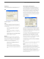
The Ethernet E-Series supports eDiags allowing radio diagnostics traffic to be carried over an IP cloud. The operation of
eDiags is as follows:
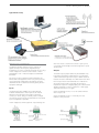
eDiags Port Settings
(1) The TView+ Diagnostics software is installed on a PC and the system design provides Ethernet connectivity between the
PC and the Diagnostics entry point radio of the Ethernet E-Series radio network.
(2) The TView+ Diagnostics software on the PC is configured with the following items:
• Create a list (database) of Ethernet E-Series radios that need to be polled for diagnostics. The IP address and eDiags
listening ports for each radio within the system should follow that of the Diagnostics Entry point radio. This will
minimise the amount of IP and Ethernet overhead transmitted over the air. The serial number for each unit must be
individually specified as well as any other information i.e Location/Name.
• Define a local listen port for incoming eDiags messages (ie: Diagnostics responses from the Diagnostics entry point
radio)
(3) Only the Diagnostics entry point radio needs to have eDiags configured and enabled. This prevents unnecessary
Ethernet/IP overhead frombeing sent over the narrowband channel.
• eDiags must be enabled (it is disabled by default)
• The eDiags local listen port must be configured. This is the port on which the eDiags server listens for incoming
eDiags polls from the TView+ Diagnostics software. The eDiags remote IP address & port must be configured. This is
the IP address of the PC running the TView+ Diagnostics software. The port is the eDiags listening port on the PC.
PC running TView+ Diagnostics
PC Locacl IP: 192.168.2.1
eDiags Local Listen Port: 4001
Diagnostics Entry point Radio
eDiags Settings for poll group
Local IP: 192.168.2.5
eDiags Local Listen Port: 4001
eDiags Remote IP: 192.168.2.1
eDiags Remote Port: 4001
*A secondary IP address can be
configured for redundant systems.
Every units eDiags settings should follow
that of the Diagnostics entry point radio.
Redundant
SCADA host
Remote unit
eDiags disabled
18
Remote unit
eDiags disabled
Remote unit
eDiags disabled
Part D – Features
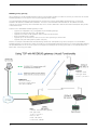
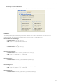
eConfig
eConfig allows access to the radio’s configuration via an Ethernet connection.
To read an Ethernet E-Series via eConfig, there must be one of two things first established:
1) eDiags enabled within entry point radio. (Note: the eDiags server is also called the eConfig server).
2) OR a terminal server installed.
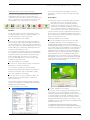
The example below will show how to perform eConfiguration using method 1 - eDiags enabled within the entry point radio.
• To begin with, the eDiags server must already be enabled & configured within the entry point radio. For configuration
instructions on eDiags, please refer to Part F - Quick Reference Guide.
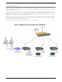
• The diagram below shows a typical point to point radio topology with eDiags enabled within the entry point radio.
PC:
IP: 192.168.2.10
Access Point:
Serial number: 600210
IP: 192.168.2.15
eDiags enabled
eDiags local port: 1040
Remote IP address: 192.168.2.10
Remote IP port: 1040
Remote Radio:
Serial number: 600220
IP: 192.168.2.16
eDiags Disabled
IP Cloud
Access Point
(radio system entry point)
Remote Radio
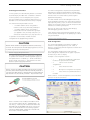
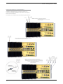
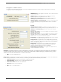
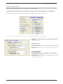
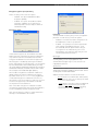
Example: Performing an eConfig read
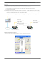
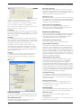
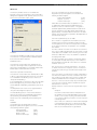
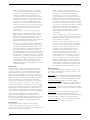
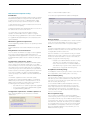
1) Open the E-Series TView+ Programmer and go to: Setting -> eConfig. As shown below.
Schneider Electric - Industry Business/Telemetry & Remote SCADA Solutions – Trio Wireless Connectivity Licensed Radio Training – Mat Del Vecchio , June 2011
1
19
Part D – Features
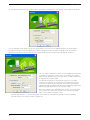
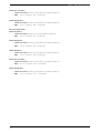
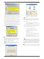
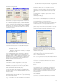
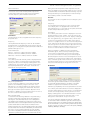
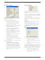
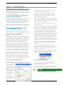
2) Once eConfig is selected as the communications port, Press the read button. This will open a new window shown below.
3) In this example, we are going to access the remote radio, so we must fill in the address details to ensure we target it.
in reference to the point to point diagram on the previous page we would fill the read unit details in with the following
information to access the remote radio. Once the details are filled, press OK and the eConfig read will commence.
• The unit’s serial number defines which unit the programmer will attempt
to establish a configuration session with. In this example, the Remote
radio is being targeted, however, any radio within the radio network may
be targeted via it’s serial number.
• The eConfig settings defines the Ethernet entry point to the radio
network. In this example, the Access point is the Ethernet Entry point
to the radio network. The eConfig server will behave as a transparent
mediator between the SCADA host PC and the radio being targeted (the
radio being targeted may also be the entry point radio).
• Note: the Local port can either be dynamic or static. if you select static,
the Local port must match the ‘Remote IP port’ setting in the target
radio. in this example is would be: 1040.
• Dynamic port selection - to use a local dynamic port, the radio you are performing a read on must be operating
firmware version 5.5.0 or later in order to support this.
20
Part D – Features
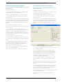
Hot Standby Redundant Ethernet Connections
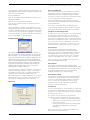
Ethernet Link Monitoring
The Ethernet Link monitoring feature has been designed to allow each base station in a hot standby arrangement to
monitor the Ethernet link to the SCADA host or Master RTU/PLC. Each base monitors the network for functional Ethernet
link connectivity by pinging a primary and a secondary IP address (typically the SCADA host(s)) and checking to see that
a response is received. This ensures that the Hot Standby arrangement does not change over to a base unit that has no
Ethernet link connectivity.
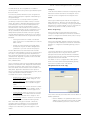
The following example shows how the Ethernet link monitoring works:
• Both base units in an EH Hot Standby “Ping Test” a Primary IP address (ie: Host A) to ensure the Ethernet network
path is healthy
• If the primary IP fails to respond, the link is declared a failure unless a secondary IP address is configured, then it will
be pinged (ie: Host B).
• In the event that both primary and secondary IP addresses do not respond to the ping test, the base declares its
“Ethernet” link has failed.
• If the failed base is online a hot standby change-over is initiated
• Ping test fail counters and wait times are user configurable.
• Time between pings and failure count threshold are user configurable.
Managed Switch configuration
Host A
• Each EB Base Ethernet port is connected to the managed
switch
• The MAC Address Cache Max-Age time in the switch should be
set to the minimum value (preferably 0) to disable caching in
the switch. This gives control of the MAC Address cache to the
online base which ensures fast link re-establishment after base
change over.
Switch/Router
Cisco 2900 or Similar
WAN
Managed Switch
Cisco 2960 or similar
IP Router
Host B
• The IP router can be configured to prevent
unnecessary Ethernet traffic being transmitted
over the SCADA radio network
• Spanning Tree Protocol and Broadcast Traffic
are typical sources of unwanted traffic
Hot Standby Controller Shared IP
The Hot Standby Controller Shared IP address can be used to access SNMP, Web server configuration menus, Telnet, eDiags,
eConfig and Terminal server functions within the “on-line” base. Each EB Base will still retain an individual IP address. Only the
“on-line” base will respond to the shared IP address.
When a Hot Standby changeover occurs, the new “on-line” base issues a Gratuitous ARP to inform any device with a MAC
cache (SCADA Host PC, Switch) that the MAC address has changed for the device owning the Common IP Address.
21
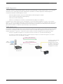
Part D – Features
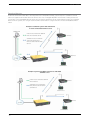
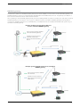
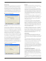
Terminal Servers
A terminal server allows serial data to be transported over a LAN/WAN. Normally, systems require a standalone terminal
server to integrate external serial devices at remotes sites into a managed LAN/WAN. The Ethernet E-Series provides the
functionality of two embedded terminal serves which avoids the requirement for an external terminal server. The examples
below show two systems, one using an external terminal server and one using the Ethernet E-Series embedded terminal
server.
Example: Traditional system without Ethernet
E-Series embedded Terminal server
SCADA HMI
IP Connection between SCADA
HMI and Terminal Server
Serial Connection between
Terminal Server, Base,
Remote and external serial
device
Remote
Serial Device
Remote
Terminal Server
Base
Serial Device
Example: System using Ethernet E-Series embedded
Terminal server
IP Connection between SCADA
HMI and Base
Remote
Serial Connection between
Base, Remote and external
serial device
Serial Device
Remote
Base
Serial Device
22
Part D – Features
Terminal Server (Virtual) Mode
When operating in virtual terminal server mode, the remote radio provides the same functionality as if there was an external
terminal server at the entry point of the system (typically a base station).
The virtual terminal server is designed to minimize the over the air bandwidth requirements by converting IP encapsulated
serial data into raw serial data. The result is that serial data can be carried over the RF channel much more efficiently than IP
encapsulated serial data, which contains additional IP and Ethernet MAC overhead for each packet of serial data transmitted.
Features of the Embedded terminal server include:
•
•
•
•
•
•
Support two independent fully configurable Virtual terminal servers.
Supports three transport protocols; TCP, UDP and PPP.
Supports three modes of TCP operation; Client mode, Server mode and Client/Server mode.
User configurable port numbers.
Supports up to 4 simultaneous TCP connections when operating in server mode.
Supports trunk and user port mode (Refer to part G user port and trunk port)
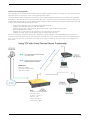
Below is an example of serial data carried over a LAN/WAN using TCP transport to the embedded terminal server of the
Ethernet E-Series base. Essentially, the Virtual Terminal server behaves as if an external terminal server was placed between
the IP connection (from the cloud) and the serial port of the entry point radio, the entry point radio in this example is the
base station.
SCADA host:
TCP client creating
connection to Base station
192.168.5.5:4001
Base:
Interface : Virtual Terminal A
Port Type : User
Tx SID = 1, Rx SID =1
Protocol : TCP
Mode : TCP Server
Local IP Port : 4001
23
Part D – Features
Device Srv (Server) Mode
When operating in device server mode, the remote radio provides the same functionality as if there was an external device
server at each remote site.
Device Server mode provides an easily configurable mechanism for transporting serial traffic that does not have any built in
addressing. The benefit of the device server feature is that device addressing can be performed using IP addresses for non
addressable serial protocols, without the need of external terminal servers or managing serial devices using the IP address of
the remote radio.
Features of the device server are the same as the features of the virtual terminal server on the previous page.
The diagram below shows a typical setup using the device server functionality in remote radios.
SCADA host:
TCP client creating
connection to ER45e #1
192.168.5.10:4001
24
Remote #1:
Interface : Device Server
Protocol : TCP
Mode : TCP Server
Local IP Port : 4001
inactivity timeout: 30s
Part D – Features
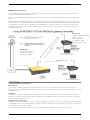
MODBUS gateway
The Ethernet E-Series has a MODBUS Gateway feature that can be enabled to function like an external MODBUS gateway. The
MODBUS gateway is a protocol converter between MODBUS/TCP and MODBUS RTU protocols. The gateway is an addition to
both the Device Server and Virtual Terminal Server features.
When operating in virtual MODBUS gateway mode, the remote radio provides the same functionality as if there was an external
MODBUS gateway at the entry point of the system. In traditional systems, standalone MODBUS gateways were required to
convert the IP MODBUS TCP protocol to MODBUS RTU, the example below shows a traditional MODBUS TCP system using a
stand alone MODBUS gateway.
Example: Traditional system without Ethernet
E-Series embedded MODBUS gateway
IP Connection between SCADA
HMI and MODBUS gateway
Remote
Serial Connection between
Terminal Server, Base,
Remote and external serial
device
Serial Device
Remote
MODBUS
gateway
Base
Serial Device
Example: System using Ethernet E-Series embedded
MODBUS gateway
IP Connection between SCADA
HMI and Base
Remote
Serial Connection between
Base, Remote and external
serial device
Serial Device
Remote
Base
Serial Device
25
Part D – Features
MODBUS gateway (Virtual)
When operating in Virtual MODBUS gateway mode, the remote radio provides the same functionality as if there was an external
MODBUS gateway at the entry point of the system (typically a base station).
The virtual MODBUS gateway ports are designed to minimise the over the air bandwidth requirements by converting IP
MODBUS TCP data into MODBUS RTU serial data . The result is that MODBUS RTU serial data can be carried over the RF
channel much more efficiently than IP MODBUS TCP, which contains additional IP and Ethernet MAC overhead for each packet
of data transmitted.
Features of the embedded MODBUS gateway include:
•
•
•
•
•
•
Support two independent fully configurable Virtual MODBUS gateways.
Supports two transport protocols; TCP and UDP.
Supports two modes of TCP operation; Client mode and Server mode.
User configurable port numbers.
Supports up to 16 simultaneous TCP connections when operating in server mode.
Supports user port mode (Refer to part G user port)
Below is an example of MODBUS RTU serial data being carried over a LAN/WAN using TCP to transport to the embedded
MODBUS gateway of the Ethernet E-Series. Essentially, the Virtual MODBUS gateway behaves as if an external MODBUS gateway
was placed between the IP connection (from the cloud) and the serial port of the entry point radio. In the example below, the
base station is the entry point radio.
Remote:
Interface : Serial
Port Type : User
Tx SID = 1, Rx SID =1
SCADA host:
TCP client creating
connection to Base station
192.168.5.5:30030
Base:
Interface : Virtual MODBUS gateway
Port Type : User
Tx SID = 1, Rx SID =1
Protocol : TCP
Mode : TCP Server
Local IP Port : 30030
26
Part D – Features
MODBUS gateway (remote)
When operating in MODBUS gateway (remote) mode, the remote radio provides the same functionality as if there was an
external MODBUS gateway at each remote site.
Features of the MODBUS gateway (remote) are the same as the features of the MODBUS gateway (virtual) on the previous
page.
MODBUS gateway mode provides an easily configurable mechanism for transporting serial traffic over an IP network (LAN/
WAN). The result of the MODBUS gateway feature is that the limitation of MODBUS addressing (0-255) can be ignored as
the IP address of the radio can be used giving unlimited addresses to external equipment such as RTUs or PLCs. Below is
an example of a typical system using the MODBUS gateway (remote) feature at each remote site to avoid the limitation of
MODBUS addressing.
Remote #1:
Interface : MODBUS gateway
Protocol : TCP
Mode : TCP Server
Local IP Port : 4001
inactivity timeout: 30s
SCADA host:
TCP client creating
connection to ER45e #1
192.168.5.10:4001
Connectivity
Independent Ethernet & Serial ports
Ethernet Port
The Ethernet E-Series is equiped with a single Ethernet port. This port is compatible with most Ethernet protocols. The
Ethernet Port is 10/100Mbps, auto MDI/MDIX sensing (NO cross over cables required). The Ethernet port operates in a Layer
2 Bridge mode.
Serial Port
The Ethernet E-Series is equipped with a single Serial port. This port is compatible with most RS-232 SCADA & Telemetry
protocols. The port’s Interface speed is user selectable (300 - 38.4 kbps asynchronous). A physical Serial port can interface
with an embedded terminal server.
Separate on-line system port
The separate system port avoids the need to interrupt user data for configuration access. The system port is always enabled
– compatible with the TView+ E&K programming cable and provides diagnostics and configuration access without requiring a
reboot or going into any special modes.
The system port also provides the ability to activate the transmitter for diagnostics and commissioning tests.
27
Part D – Features
Radio and Modem Features
Radio
Remotes are available in half duplex & simplex modes (useful for remote sites in PTMP systems). They are also available in a
full duplex version (useful for PTP links). Full duplex allows Tx & Rx operation to occur simultaneously.
Power Supply
The ER45e remote will operate between a DC voltage range of 10 - 30V (13.8VDC Nominal). This eliminates the requirement
of DC-DC converters on sites operating at 24VDC.
Ethernet E-Series base stations and hot standby controllers operate between a DC voltage range of 11 - 16 V (13.8VDC
Nominal).
Collision Avoidance
ChannelShare™ unique integrated C/DSMA collision avoidance technology permits simultaneous polling and spontaneous alarm
reporting operation in the same system. Collision avoidance operates on the principle of one device, called the collision avoidance
master, managing remote access to the RF channel.
Collisions will occur on the receiving channel of the master, due to two or more remotes transmitting simultaneously. ChannelShare™
minimizes the chance of collisions by using the collision avoidance master to inform remotes when access to the RF channel is
available.
Remotes will check whether the master is allowing access to the channel before a transmission occurs. If the channel is free,
the remote will transmit, if the channel is busy, the remote will buffer the message and execute a small random delay (in case
multiple remotes have data to send), then attempt to access the channel again.
There are two different modes of operation that ChannelShare™ can use:
Carrier Detect - which uses the TX carrier of the collision avoidance master to indicate if channel is busy
Digital - which requires a permanently keyed (transmitting) collision avoidance master.
In this mode the busy state of the channel is indicated by a digital data stream bit constantly transmitted by the master. This
mode of collision avoidance has a smaller collision window than the carrier detect mode.
In digital collision avoidance mode, the remote radio can be programmed for two types of operation:
Remote Tx data ‘Priority’:(Original remote default)
• Tx Priority only observes the digital collision avoidance masters channel busy flag. Essentially this mode waits for the
channel busy bit to be clear then it will send any data it needs to.
Remote Rx data ‘Priority’:
• In some Ethernet systems, particularly where multiple threads are started (ie: browsing web pages), a problem can occur
due to the half-duplex nature of the radio. The problem may occurs because the remote will prioritising Tx data, which may
potentially corrupt incoming Rx data. To prevent this, enabled the Remote Rx data Priority mode. Rx Priority does not only
observe the digital collision avoidance masters channel busy flag, but also gives priority to incoming data being received.
Essentially this mode waits for incoming data to be complete, then it sends the data (proving the channel busy flag is still
clear).
TM
Multistream
functionality (SID codes)
Due to the non addressable nature of Serial only data, Stream Identification (SID) codes have been implemented to give users
the ability to route Serial messages to their correct destinations. Addresses can be implemented between a range of 0-255.
These SID codes will create virtual circuits between sites to allow message routing.
Serial Digipeater Operation
The Ethernet E-Series has the ability to internally repeat serial data packets to provide stand alone repeater facilities without the
need for external intelligence.
Security
Secure operation with 128-bit AES encryption**
The 128-bit AES encryption feature can provide an encrypted channel that prevents eaves-dropping and snooping. The
effort for configuration is minimal as the radio automatically adjusts, to keep packet transport compatible (i.e.: MODBUS
messages are not broken up). Enabling encryption requires additional overhead depending on packet sizes being sent. For
more detailed information, refer to Trio tech note TN80.
Password Protected Configurations
Configuration information can be protected by a user definable password. When a password is set, the programmer will
request the password each time the radio is read. No configuration information can be displayed or changed without the
correct entry of the password.
28
Part E – Getting Started - ER45e
Part E – Getting Started
Understanding RF Path Requirements
A radio modem needs a minimum amount of received RF signal to operate reliably and provide adequate data throughput.
In most cases, spectrum regulatory authorities will also define or limit the amount of signal that can be transmitted, and the
transmitted power will decay with distance and other factors, as it moves away from the transmitting antenna.
It follows, therefore, that for a given transmission level, there will be a finite distance at which a receiver can operate reliably
with respect to the transmitter.
Apart from signal loss due to distance, other factors that will decay a signal include obstructions (hills, buildings, foliage),
horizon (effectively the bulge between two points on the earth), and (to a minimal extent at UHF frequencies) factors such as
fog, heavy rain-bursts, dust storms, etc.
In order to ascertain the available RF coverage from a transmitting station, it will be necessary to consider these factors. This
can be done in a number of ways, including
(a)
using basic formulas to calculate the theoretically available signal - allowing only for free space loss due to distance,
(b)
using sophisticated software to build earth terrain models and apply other correction factors such as earth curvature
and the effects of obstructions, and
(c)
by actual field strength testing.
It is good design practice to consider the results of at least two of these models to design a radio path.
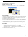
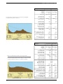
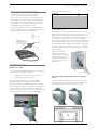
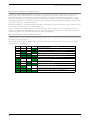
Examples of Predictive Path Modelling
Clear line of site
Radio path with good signal levels, attenuated only by
free space loss.
Obstructed Radio Path
goodpath.pl3
Major Repeater Site
Field Site
Elevation (m)
Latitude
Longitude
Azimuth
756.69
031 04 37.49 S
150 57 26.34 E
297.05
309.67
030 56 24.00 S
150 38 48.00 E
117.21
Antenna Type
Antenna Height (m)
Antenna Gain (dBi)
Antenna Gain (dBd)
ANT450/6OM
40.00
8.15
6.00
ANT450/9AL
5.00
11.15
9.00
TX Line Type
TX Line Length (m)
TX Line Unit Loss (dB/100 m)
TX Line Loss (dB)
Connector Loss (dB)
LDF4-50
40.00
6.79
2.72
2.00
LDF4-50
5.00
6.79
0.34
2.00
Frequency (MHz)
Path Length (km)
Free Space Loss (dB)
Diffraction Loss (dB)
Net Path Loss (dB)
Radio Type Model
TX Power (watts)
TX Power (dBW)
Effective Radiated Power (watts)
Effective Radiated Power (dBW)
RX Sensitivity Level (uv)
RX Sensitivity Level (dBW)
RX Signal (uv)
RX Signal (dBW)
RX Field Strength (uv/m)
Fade Margin (dB)
Raleigh Service Probability (%)
450.00
33.33
115.99
0.00
103.75
EB450
103.75
ER450
5.00
6.99
6.71
8.27
0.71
-140.00
1.00
0.00
4.63
6.66
1.26
-135.00
45.93
-103.75
453.14
36.25
99.976
102.70
-96.76
545.42
38.24
99.985
29
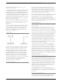
Part E – Getting Started - ER45e
obstpath.pl3
This path has an obstruction that will seriously degrade
the signal arriving at the field site.
Major Repeater Site
Elevation (m)
Latitude
Longitude
Azimuth
703.83
030 43 55.92 S
150 38 49.51 E
180.10
309.67
030 56 24.00 S
150 38 48.00 E
0.10
Antenna Type
Antenna Height (m)
Antenna Gain (dBi)
Antenna Gain (dBd)
ANT450/6OM
40.00
8.15
6.00
ANT450/9AL
5.00
11.15
9.00
TX Line Type
TX Line Length (m)
TX Line Unit Loss (dB/100 m)
TX Line Loss (dB)
Connector Loss (dB)
LDF4-50
40.00
6.79
2.72
2.00
LDF4-50
5.00
6.79
0.34
2.00
Frequency (MHz)
Path Length (km)
Free Space Loss (dB)
Diffraction Loss (dB)
Net Path Loss (dB)
Radio Type Model
TX Power (watts)
TX Power (dBW)
Effective Radiated Power (watts)
Effective Radiated Power (dBW)
RX Sensitivity Level (uv)
RX Sensitivity Level (dBW)
RX Signal (uv)
RX Signal (dBW)
RX Field Strength (uv/m)
Fade Margin (dB)
Raleigh Service Probability (%)
longpath.pl3
Antenna Type
Antenna Height (m)
Antenna Gain (dBi)
Antenna Gain (dBd)
This path requires greater mast height to offset the earth
curvature experienced at such a distance (73km).
TX Line Type
TX Line Length (m)
TX Line Loss (dB)
Connector Loss (dB)
Frequency (MHz)
Path Length (km)
Free Space Loss (dB)
Diffraction Loss (dB)
Net Path Loss (dB)
30
450.00
23.04
112.78
16.71
117.25
117.25
EB450
ER450
5.00
6.99
6.71
8.27
0.71
-140.00
1.00
0.00
4.63
6.66
1.26
-135.00
9.70
-117.25
95.74
22.75
99.470
21.70
-110.26
115.23
24.74
99.665
Repeater Site
Elevation (m)
Latitude
Longitude
Azimuth
Effect of Earth Curvature on Long Paths
Field Site
221.26
032 01 21.63 S
142 15 19.26 E
217.12
ANT450/6OM
40.00
8.15
6.00
Far Field Site
75.58
032 33 00.00 S
141 47 00.00 E
37.37
ANT450/9AL
5.00
11.15
9.00
LDF4-50
40.00
6.79
2.72
2.00
450.00
73.46
122.85
22.94
133.55
LDF4-50
5.00
6.79
0.34
2.00
133.55
Radio Type Model
TX Power (watts)
TX Power (dBW)
Effective Radiated Power (watts)
Effective Radiated Power (dBW)
RX Sensitivity Level (uv)
RX Sensitivity Level (dBW)
EB450
5.00
6.99
6.72
8.27
0.71
-140.00
ER450
1.00
0.00
4.64
6.66
1.26
-135.00
RX Signal (uv)
RX Signal (dBW)
RX Field Strength (uv/m)
Fade Margin (dB)
Raleigh Service Probability (%)
1.49
-133.55
14.65
6.45
79.735
3.32
-126.56
17.64
8.44
86.656
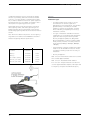
Part E – Getting Started - ER45e
There are basically two types of antennas – omnidirectional and directional.
Omnidirectional antennas are designed to radiate signal
in a 360 degrees segment around the antenna. Basic
short range antennas such as folded dipoles and ground
independent whips are used to radiate the signal in a
“ball” shaped pattern. High gain omni antennas such as
the “co-linear” compress the sphere of energy into the
horizontal plane, providing a relatively flat “disc” shaped
pattern which goes further because all of the energy is
radiated in the horizontal plane.
Directional antennas are designed to concentrate the
signal into “beam” of energy for transmission in a single
direction (i.e. For point-to-point or remote to base
applications).
Beamwidths vary according to the antenna type, and so
can be selected to suit design requirements. The most
common UHF directional antenna is the yagi, which
offers useable beam widths of 30-50 degrees. Even
higher “gain” is available using parabolic “dish” type
antennas such as gridpacks.
Antenna Gain
By compressing the transmission energy into a disc or
beam, the antenna provides more energy (a stronger
signal) in that direction, and thus is said to have a
performance “gain” over a basic omni antenna. Gain
is usually expressed in dBd, which is referenced to a
standard folded dipole. Gain can also be expressed
in dBi, which is referenced to a theoretical “isotropic”
radiator. Either way, if you intend to send and receive
signals from a single direction, there is advantage in
using a directional antenna - both due to the increased
signal in the wanted direction, and the relatively
decreased signal in the unwanted direction (i.e.
“Interference rejection” properties).
Tuning the Antenna
Many antennas are manufactured for use over a wide
frequency range. Typical fixed use antennas such as folded
dipoles and yagis are generally supplied with the quoted
gain available over the entire specified band range, and do
not require tuning. Co-linear antennas are normally built to a
specific frequency specified when ordering.
With mobile “whip” type antennas, it is sometimes necessary
to “tune” the antenna for the best performance on the
required frequency. This is usually done by trimming
an antenna element whilst measuring VSWR, or simply
trimming to a manufacturer supplied chart showing length vs
frequency. These antennas would normally be supplied with
the tuning information provided.
Antenna Placement
When mounting the antenna, it is necessary to consider the
following criteria:
The mounting structure will need to be solid enough to
withstand additional loading on the antenna mount due to
extreme wind, ice or snow (and in some cases, large birds).
For omni directional antennas, it is necessary to consider the
effect of the mounting structure (tower mast or building) on
the radiation pattern. Close in structures, particularly steel
structures, can alter the radiation pattern of the antenna.
Where possible, omni antennas should always be mounted
on the top of the mast or pole to minimise this effect. If
this is not possible, mount the antenna on a horizontal
outrigger to get it at least 1-2m away from the structure.
When mounting on buildings, a small mast or pole (2-4m)
can significantly improve the radiation pattern by providing
clearance from the building structure.
For directional antennas, it is generally only necessary to
consider the structure in relation to the forward radiation
pattern of the antenna, unless the structure is metallic, and
of a solid nature. In this case it is also prudent to position
the antenna as far away from the structure as is practical.
With directional antennas, it is also necessary to ensure that
the antenna cannot move in such a way that the directional
beamwidth will be affected. For long yagi antennas, it is often
necessary to install a fibreglass strut to stabilise the antenna
under windy conditions.
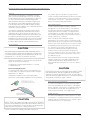
Alignment of Directional Antennas
This is generally performed by altering the alignment of the
antenna whilst measuring the received signal strength. If the
signal is weak, it may be necessary to pre-align the antenna
using a compass, GPS, or visual or map guidance in order
to “find” the wanted signal. Yagi antennas have a number of
lower gain “lobes” centred around the primary lobe. When
aligning for best signal strength, it is important to scan the
antenna through at least 90 degrees, to ensure that the
centre (strongest) lobe is identified.
When aligning a directional antenna, avoid placing your
hands or body in the vicinity of the radiating element or the
forward beam pattern, as this will affect the performance of
the antenna.
RF Feeders and Protection
The antenna is connected to the radio modem by way
of an RF feeder. In choosing the feeder type, one must
31
Part E – Getting Started - ER45e
compromise between the loss caused by the feeder,
and the cost, flexibility, and bulk of lower loss feeders.
To do this, it is often prudent to perform path analysis
first, in order to determine how much “spare” signal can
be allowed to be lost in the feeder. The feeder is also a
critical part of the lightning protection system.
All elevated antennas may be exposed to induced or
direct lightning strikes, and correct grounding of the
feeder and mast are an essential part of this process.
Gas discharge lightning arresters should also be fitted to
all sites.
Note: All ETSI installations require the use of a lightning
surge arrestor in order to meet EN60950. See Part A Preface for lightning arrestor specifications.
Common Cable Types
450MHz
@
Loss per meter
@ 450MHz
Loss per 10m
RG58C/U
0.4426dB4.4dB
RG213/U
0.1639dB1.6dB
FSJ1-50 (¼” superflex)
0.1475dB
1.5dB
LDF4-50 (1/2” heliax)
0.0525dB
0.52dB
LDF5-50 (7/8” heliax)
0.0262dB
0.3dB
32
Modem
Modulation Types
• The radio modem utilises a DSP to control
the modulation of transmit signals and
demodulation of received signals. This provides
greater flexibility in the ability of the radio
modem to support new modulation schemes
whilst maintaining compatibility with existing
modulation schemes.
• The type of modulation available for selection
is dependent on the model of radio. Modulation
types are sorted using the following criteria:
Country of Approval (FCC, ETSI, ACA), Radio
Channel Bandwidth (12.5kHz or 25kHz), Radio
Mode (E Series, M Series or D Series) and over
the air speed (2400bps, 4800bps, 9600bps,
19k2bps).
• Only modulation schemes suitable for the radio
model in use are available for selection. Please
consider the following notes when choosing a
modulation.
• Country of Approval :
FCC : for use in North America and other countries
who use FCC approved radios.
ACA : for use in Australia and New Zealand.
ETSI : for use in Europe and other countries who
use ETSI approved radios.Simplex, Half Duplex and
Full Duplex (Full Duplex with ERFD450 option)
Part E – Getting Started - ER45e
Power Supply and Environmental Considerations
General
When mounting the equipment, consideration should be
given to the environmental aspects of the site. The cabinet
should be positioned so that it is shaded from hot afternoon
sun, or icy cold wind. Whilst the radios are designed for
harsh temperature extremes, they will give a longer service
life if operated in a more stable temperature environment.
In an industrial environment, the radio modems should be
isolated from excessive vibration, which can destroy electronic
components, joints, and crystals.
The cabinet should provide full protection from moisture,
dust, corrosive atmospheres, and residues from ants and
small vermin (which can be corrosive or conductive). The
radio modem will radiate heat from the in-built heatsink, and
the higher the transmitter duty cycle, the more heat will be
radiated from the heatsink. Ensure there is sufficient ventilation
in the form of passive or forced air circulation to ensure that
the radio is able to maintain quoted temperature limits.
Power Supply
Operating Voltage Range
CAUTION
The power supply should provide a clean, filtered DC source.
The ER45e modem is designed and calibrated to operate from
a 13.8VDC regulated supply, but will operate from 10-30 volts
(filtered) DC, or 11-16 volts For an EB45e or EH45e.
The ER45e Device will operate between a DC Voltage
Range of 10 - 30V (13.8VDC Nominal). if the operating
voltage is exceeded the E series Ethernet remote will self
protect by opening its internal fuse.
The EB/EH45e models operate between 11-16VDC
(13.8VDC Nominal).
Reverse Polarity Protection
The internal power supply circuitry of the ER45e has an
in series diode. The fuse will not blow if reverse voltage is
applied that is <= 30V DC.
The EB/EH45e models DO NOT have reverse polarity
protection, if reverse polarity is applied the units fuse will blow.
The power supply must be able to supply sufficient
current to provide clean filtered DC under the full current
conditions of the radio modem (i.e. When transmitting
full RF power). See Section L - Specifications for more
details of the power supply requirements.
Solar Applications
In solar or battery-backed installations, a battery
management unit should be fitted to cut off power to
the radio when battery levels fall below the minimum
voltage specification of the radio. In solar applications,
a solar regulation unit MUST ALSO be fitted to ensure
that the radio (and battery) is protected from excessive
voltage under full sun conditions.
When calculating solar and battery capacity
requirements, the constant current consumption will be
approximately equal to the transmit current multiplied by
the duty cycle of the transmitter, plus the receive current
multiplied by the (remaining) duty cycle of the receiver.
The Tx/Rx duty cycle will be entirely dependent on
the amount of data being transmitted by the radio
modem, unless the device has been configured for
continuous transmit, in which case the constant current
consumption will be equal to the transmit current only
(at 100% duty cycle).
Note: Operation below the minimum specified supply
voltages could result in poor radio performance. If the
supply voltage falls below 10Vdc the radio will shut
down. Normal radio startup will not occur until 10Vdc is
supplied.
CAUTION
Ensure that the chassis mounting plate, power supply (-) earth,
RTU terminal device, and lightning arrester, are all securely
earthed to a common ground point to which an earth stake is
attached. Please pay particular attention to 24Vdc PLC systems
using DC-DC converters to supply 13.8Vdc.
High Temperature Foldback
The ER45e will foldback the Transmit power by 6dBm
if the internal temperature sensor detects +70 degrees
Celsius or greater. If the remote is in foldback mode and
the temperature is measured +67 degrees Celsius or
lower, the power will return to its original state.
VSWR Sensing
CAUTION
The ER45e will foldback the Transmit power to +31dBm
if a VSWR of 3:1 or greater is detected. If the remote is in
foldback mode and a VSWR level of 2:1 or lower is taken,
the power will return to its original state.
Caution: There is NO readily serviceable internal fuse for an EB45e
or EH45e, and therefore they both MUST be externally fused with a
fuse and fuse holder (EB45e: 5 amp fast-blow fuse, EB45e(20W):
8 amp fast blow fuse, EH45e: 1 amp slow blow fuse).
NOTE: The ER45e has a readily serviceable internal fuse.
33
Part E – Getting Started - ER45e
Physical Dimensions - Remote Data Radio - ER45e
34
Part E – Getting Started - ER45e
Physical Dimensions - Mounting Cradle/Din Rail Mount
ER45e only (Optional)
Mounting Cradle
ER45e Mounting Cradle
The ER45e mounting cradle comes standard with the x4 mounting posts. If you want to purchase a new unit
equip with the Din Rail mount, you can either request to have the units sent with the Din Rail mount already
screwed onto the mounting cradle or have the Din Rail mount supplied separately along with x4 screws and x4
washers (screws: 3x8 Pan head, Washers: 3mm Spring washers). In the case of attaching the Din rail mounts to
older radios, please ensure that you radio’s mounting cradle has the x4 mounting posts.
Din Rail Mount (Optional)
3.5mm Din Rail
Din Rail Mount
The Din Rail Mount is an optional feature. The Mount is screwed onto the bottom of an ER45e Mounting Cradle
giving the unit the ability to be simply ‘clipped’ and Locked onto 3.5mm Din Rail.
35
Part E – Getting Started - ER45e
Hole drilling template
ER45e Mounting Cradle
The image below is a 1:1 scale of the mounting plate of an E-Series remote. This page can be printed off
and used as a hole drilling template. Once you print the template out please measure it and compare your
measurements to the specs printed to ensure scaling is correct.
36
Part E – Getting Started - ER45e
Physical Dimensions - Base Station - EB45e
*Note: 459mm
for 20W version
Base
37
Part E – Getting Started - ER45e
Physical Dimensions - Hot Standby Base - EH45e
*Note: 459mm
for 20W version
Base
38
Part E – Getting Started - ER45e
ER45e Quick Start Guide
Mounting and Environmental Considerations
Introduction
The ER45e radio comes complete with a mounting
cradle and is attached to a panel or tray by means of
screws or bolts, using the hole slots provided.
Welcome to the Quick Start Guide for the ER45e
Ethernet Radio. This guide provides step-by-step
instructions, with simple explanations to get you up-andrunning.
Note: In high power or high temperature applications,
it is desirable to mount the radio with the heatsink
uppermost to allow ventilation for the heatsink.
The radio should be mounted in a clean and dry location,
protected from water, excessive dust, corrosive fumes,
extremes of temperature and direct sunlight. Please
allow sufficient passive or active ventilation to allow the
radio modem’s heatsink to operate efficiently.
CAUTION
ER45e Connections Layout
System
Data
Port
LAN
Port
Warning: Where an ER45e is to be operated between 45°C
and 70°C ambient, it must be installed in a restricted access
location to reduce the risk of somebody being burt.
DC
input
Antenna
Typical Radio Setup
Omni-Directional or
Direction Yagi Antenna
Lightning
Arrestor
Ethernet E-Series
Mains Supply
Ethernet Device (RTU/PLC)
Connected to LAN port
Regulated Power Supply
(110/220VAC to 13.8
VDC Nominal)
Laptop/PC running TView+
Diagnostics Connected to
System Port
39
Part E – Getting Started - ER45e
Connecting Antennas and RF Feeders
The RF antenna system should be installed in
accordance with the manufacturers notes.
The RF connector used on the E Series radios are N
Type female connectors. Always use good quality low
loss feeder cable, selected according to the length
of the cable run. Ensure all external connections are
waterproofed using amalgamating tape.
Preset directional antennas in the required direction
using a compass, GPS, or visual alignment and ensure
correct polarisation (vertical or horizontal).
TView+ Adaptor Configuration:
System
Port
Pin 1
Pin 2
Pin 3
Pin 4
Pin 5
Pin 6
Pin 7
Pin 8
Description
System port data out (RS232)
System port data in (RS232)
Factory Use Only - Do not connect
Shutdown
Programming Use Only (Grounded)
Factory Use Only - Do not connect
Ground
External PTT
DB9 Female
Pin 2
Pin 3
No Connection
No Connection
Pin 5
No Connection
Pin 5
No Connection
Special user pinouts:
Shutdown (Pin 4) - Active low for power save function In
order to put the radio into Shutdown mode, tie pin 4 to a
digital output on a SCADAPack, RTU or similar device. When
it is desired to turn the radio off, switching this digital output
must connect the radio’s pin 4 to ground. The (earth)
ground of both devices would also need to be tied together
as a common reference. (Pin 7 on the radio’s System port)
A 2 wire cable between SCADAPack and radio system port
is all that’s required, with an RJ-45 connector on the radio
end. The Shutdown pin may be left floating for the radio to
remain powered.
External PTT (Pin 8) Provides a manual PTT
override facility for enabling
the transmitter. For testing
this can be activated by
connecting PTT (Pin 8 ) to
Gnd (Pin 7).
Communications Ports
System Port – RJ45
The System Port (available front and rear on EB/EH45e)
is a multi-function interface used for:
• Programming / Configuration of the radio
• Remote Diagnostics connections
To access these functions use the TView+ Cable
assembly (RJ45 Cable and RJ45 to DB9 Adaptor).
The TView+ Cable is a standard CAT 5 RJ-45 (Male) to
RJ-45 (Male) patch cable. It is intended for RS232 serial
communications only and should not be connected
directly into an Ethernet port of a PC. The Cable must be
used in conjunction with the RJ-45 to DB9 Adaptor.
40
Cross Over cable (Trunking System Port to System
Port)
Some circumstances require a user to trunk the system
ports of two units using an RJ45 cross over cable. Follow
the diagram below to create the cross over cable.
Part E – Getting Started - ER45e
Data Port
RS232 Connector Pin outs (DCE)
Data Port, Female DB9
The Data Port is wired as a RS232 DCE, configurable for
no handshaking (3-wire) interface, or for hardware or
software (X-on/X-off) flow control. In most systems flow
control is not required, in which case only 3 wires need
to be connected between the radio and the application
device.
Typical pins used:
• Pin 2 (RxD) - data output from the radio modem,
• Pin 3 (TxD) - data input to the radio modem,
• Pin 5 (SG) - signal ground.
41
Part E – Getting Started - ER45e
LAN Ethernet Port
Performing a Factory Default
The LAN port is a 10/100 Base-T compliant port using an
RJ-45 connector. These ports support both TIA/EIA-568-A
& B wiring as they have Auto MDI/MDIX Auto Sensing. This
means you can use both straight-through and cross-over
type CAT-5 or better patch cables. All RJ45 connectors
must utilize mating plugs that include an integral locking
tab.
Please read the following notes carefully.
Configuration errors with Ethernet connections can
be difficult to find and resolve. It is strongly recommended
that you follow these guidelines.
IP Address and Factory Default Reset
The factory default IP address of an E Series Ethernet
radio is 192.168.2.15. If you do not know the IP address
of the E Series Ethernet radio you can either read the unit
using the TView programmer or perform a factory default.
A factory reset will cause all previous configuration settings
to be erased and returned to the factory default values. A
factory default can be initiated by applying DC power to the
radio (wait 45 seconds), depress the factory default switch
using a paper clip or similar object and keep the switch
depressed for 5 seconds until all five LEDs illuminate solid
GREEN indicating the radio will return to the factory default
settings. Please wait 45 seconds for the factory default
reset process to complete.
Factory Default Button
If termination of a cable is required, then the following
wiring arrangement should be followed (Compliant with TIA/
EIA-568-A).
Note: Maximum differential voltage : 5v, 50mA max through each differential
pair.
Note: If 100-BaseT connection speed is required, CAT-6
Shielded cable should be used for installation to comply
with ETSI EMC directives.
42
Part E – Getting Started- ER45e
Activating the Transmitter
In most systems, the transmitter by default is controlled
automatically by the radio when it has data to transmit.
In some systems, such as full duplex point-to-point
links or full duplex point-to-multipoint base stations, it is
desirable to run the transmitter all the time (hot keyed).
Two mechanisms are provided to do this:
• The radio modem can be configured to
transmit continuously whenever powered, or
• The radio modem can be configured to
transmit whenever an external RTS signal (Pin
7) is applied to one (or either) user ports. (To
simulate an external RTS input, loop pins 6 to 7).
To operate in these modes, the radio must be
configured via the programming software.
CAUTION
Caution: When a radio is configured to transmit continuously,
ensure an RF load is present BEFORE applying power to the unit,
to prevent high levels of reverse power.
Power Supply Requirements
The ER45e Ethernet modem is designed and calibrated
to operate from a filtered 13.8Vdc regulated supply, but
will operate from a 10-30Vdc (11-16Vdc for EB45e &
EH45e) range. See Section L - Specifications for more
details on power supply requirements
CAUTION
Caution: There is NO readily serviceable internal fuse for an EB45e
or EH45e, and therefore they both MUST be externally fused with a
fuse and fuse holder (EB45e: 5 amp fast-blow fuse, EB45e(20W): 8
amp fast blow fuse, Hot standby controller: 1 amp slow blow fuse).
The ER45e is designed to self protect from permanent
damage if the voltage exceeds 30VDC. The radio may
need to be returned for service if this occurs. The ER45e
remotes have an in Series Diode to protect against
applied reverse polarity.
The radio modem can also be damaged if there is any
potential difference between the chassis-ground, RS232
signal ground, power (-) input, or antenna coaxial shield.
Before connecting any wiring, ensure all components are
earthed to a common ground point.
Connect the antenna, RS 232 plug and LAN plug
BEFORE applying power to the unit.
Lastly, before inserting the power plug, please re-check
that the polarity and voltage on the power plug is correct
using a multimeter.
TView+ Management Suite
Radio Configuration
This TView+ Management Suite allows a number of
features including: Configuration (Local - serial, or
Remote - over-the-air), Remote Diagnostics Facilities and
Firmware Upgrades.
The configuration wizard can be used to provide
Quick Start generic templates for the types of systems
architecture you wish to employ.
Example: Local configuration session –
• 1
Attach the programming cable from
the PC to the System Port of the radio
• 2
Launch TView+ & Select
“Programmer”
• 3
Select “Read” the radio
• 4
Change the configuration as required
• 5
Select “Write” the parameters back to
the radio
Refer to Part G – TView+ Management Suite for detailed
operation of advanced features.
NOTE: The ER45e has a readily serviceable internal
fuse Trio Part number: Part No. SM%FUSSQ5A) 5A
Fast Acting – Littelfuse part numbers 0451005. MRL,
0453005.MR and 0448005.MR can be used. These
fuses can be obtained from the following suppliers:
Farnell P/N: 9922199RL, Digikey P/N: F2587CT-ND,
Mouser P/N: 576-0451005.MRL
43
Part E – Getting Started- ER45e
Optimising the Antenna for best RX signal
Once the unit is operational, it is important to optimise
the antenna tuning.
In the case of a directional antenna, it will be necessary
to align the antenna for the best received signal.
This can be done by using the (0-5VDC) output on Pin
9 of the Data Port to indicate signal strength (RSSI). This
voltage can be converted to dBm using the chart below.
LED Indicators & Test Outputs
Radio is Powered
If all the LEDs are off, no power is reaching the radio
modem.
Successful power-up is indicated by the “PWR” LED
indicating a continuous (healthy) GREEN state. Note that
this LED is turned RED when the transmitter is active.
Data Port, Pin 9, RSSI output
Radio Errors
Data Port, Pin 5, Signal Ground
Analog RSSI Output Characteristics - E Series Data Radio
Note (1): If external voltage is too high (>30Vdc)
radio damage may occur. If the external voltage is
too low (<10Vdc) the radio may not operate within
specifications.
5
4.5
RSSI (DC Volts)
4
3.5
3
2.5
2
1.5
1
0.5
0
-120
-110
-100
-90
-80
-70
-60
-50
-40
RF Level (dBm)
Please note that the RSSI table values are for indicative
use only.
44
Internal radio management software monitors
many aspects of the radio hardware. Under certain
circumstances radio faults may prevent normal
operation. In the event that these fault conditions
occur, the radio will enter an ERROR state and this will
be indicated by flashing ALL LEDs RED, then flashing a
pattern of GREEN or AMBER LEDs. The pattern of GREEN
LEDs represents the specific type of error that has
occurred. All other patterns indicate serious hardware
errors. Please record this pattern and return the result
with the service return information.
Note (2) and (3): If the radio receiver or transmitter
frequencies are programmed outside the specified
frequency ranges (model type dependent), then normal
radio operation may not be possible. In this case, use
TView+ to set the receiver and/or transmitter frequencies
to be within the specified range. If this error occurs
and the frequencies are within the specified frequency
ranges (model type dependent), the radio will need to be
returned for service.
Part E – Getting Started- ER45e
Received Signal Indicator
Verifying Operational Health
The “RX/SYNC” LED is used to indicate the state of the receiver.
It is possible to verify the operation of the radio modem
using the indicators provided by the unit. The state
of the transmitter and receiver, and data flow can be
interpreted by the indicator LEDs (see below).
If the LED is off, no signal is being received.
A RED indication shows that an RF carrier is being
received, but no data stream can be decoded. This
will briefly happen at the very start of every valid
received transmission or may indicate the presence of
interference, or another user on the channel.
A continuous GREEN indication shows that the modem
is locked and synchronised to the incoming signal,
and has excellent Bit Error Rate (BER). Any losses of
synchronisation (BER errors) are shown as a visible RED
flicker of the LED.
Note: LAN Port and Data Port’s RxD and TxD will be
Active on Data Flow
Full Duplex – PTP Master or Slave
Note: This might only be apparent on a PTMP slave when
only receiving.
Full Duplex – PTMP Master Tx
Half Duplex – PTMP Slave Rx
Data Flow “breakout” LEDs
There are also two LEDs to indicate data flow into and
out of the two user ports.
Input data to be transmitted is shown as a RED flash,
and received data to be output to the port is shown as a
GREEN flash.
Half Duplex – Master or Slave (Tx)
If data is alternately flowing in and out quickly, then the
indicator appears orange.
Half Duplex – Master or Slave (Rx)
45
Part E – Getting Started - EB450
EB45e Quick Start Guide
20W Power Amplifier option
Introduction
The 20W power amplifier is primarily used for the purpose of
overcoming Tx combiner losses. In such cases of a 20W power
amplifier being required, an Rx preamp may also be required.
Welcome to the Quick Start Guide for the EB45e Base
/ Repeater Ethernet Radio. This guide provides step-bystep instructions, with simple explanations to get you
up-and-running.
Note: 20W power amplifier options may not be available in all
Countries. Please contact the factory to confirm availability.
Mounting and Environmental Considerations
Power Supply and Protection
The EB45e Base Station is housed in a 2RU 19” rack
enclosure. The 4 mounting holes on the front panel should
be used to secure the unit to the rack.
The power supply should provide a clean, filtered DC
source. The EB45e Ethernet Radio is designed and
calibrated to operate from a 13.8VDC regulated supply,
but will operate from 11-16 volts (filtered) DC.
The radio should be mounted in a clean and dry location,
protected from water, excessive dust, corrosive fumes,
extremes of temperature and direct sunlight. Please allow
sufficient passive or active ventilation to allow the radio
modem’s heatsink to operate efficiently.
All permanent connections are made at the rear of the unit.
This includes: Power, Antenna, Communications Ports, Digital
I/O and System Port. The front panel has an additional System
Port connection point for easy access.
CAUTION
Warning: Where an ER45e is to be operated between 45°C and
60°C ambient, it must be installed in a restricted access location
to reduce the risk of somebody being burnt.
The power supply must be able to supply sufficient
current to provide clean filtered DC under the full current
conditions of the radio modem (i.e. When transmitting
full RF power). See Section L - Specifications for more
details of the power supply requirements.
Connecting Antennas and RF Feeders
See ER45e Quick Start Guide
CAUTION
Caution: There is NO readily serviceable internal fuse for an EB45e
or EH45e, and therefore they both MUST be externally fused with a
fuse and fuse holder (EB45e: 5 amp fast-blow fuse, EB45e(20W):
8 amp fast blow fuse, hot standby controller: 1 amp slow blow fuse).
Full Duplex Considerations
Communications Ports
The EB45e is designed for continuous full duplex
transmission. An automatic thermostatically controlled fan
will operate whenever the internal temperature exceeds 40
degrees Celsius and turn off again when the temperature
goes below 35 degrees Celsius.
See ER45e Quick Start Guide Section
External Duplexer Considerations
The EB45e is normally supplied with separate Tx and Rx
ports for connection to an external duplexing system.
Depending on the frequency band of operation and the Tx/Rx
frequency split, internal band reject duplexers are available.
46
TView+ Management Suite - Radio
Configuration
See ER45e Quick Start Guide Section
Optimising the Antenna for VSWR and best RX
signal
See ER45e Quick Start Guide Section
Part E – Getting Started - EB450
Typical Radio Setup
Digital Inputs and Outputs
The EB45e provides a facility for two channels of
digital user inputs and outputs (Digital User I/O).
Information on how to control and monitor this I/O using
TView+ Diagnostics can be found in Part G - TView+
Management Suite - Remote Diagnostics & Network
Controller.
All user I/O is optocoupled for isolation between the
EB45e and uses equipment. When using the I/O facility
the I/O electrical characteristics and ratings must be
observed. Failure to observe these ratings may result in
equipment damage.
Inputs
Two User Inputs are available. They have identical
interface characteristics. Each input has an internal
resistance of 470 Ohms. Some form of switching
contact (i.e: switch, relay) is normally used to change
the state of the input. Both an isolated and non-isolated
input configuration is possible.
when the switch is closed. If the switch is open (or not
connected) TView+ diagnostics will recognise the inputs
as being OFF.
Outputs
Two User Outputs (Open Collector) are available. They
have identical interface characteristics. The maximum
current allowed through each output is 20mA. External
resistors must be used keep the current below this value.
Each output has an internal resistance of 100 Ohms.
Ohms law can be used to calculate the resistance
required for a specific voltage (keeping the current below
20mA). Nominally 1K Ohm is used for a +13v8 supply
and 330 Ohms for a +5v supply.
When the OUTPUT is OFF, V = Vs. No current will flow
when output is off.
When the OUTPUT is ON, V = nominally 2.3 volts .
Current is set by resistor.
TView+ Diagnostics will recognise an input as being ON
Is
47
Part E – Getting Started - EB450
LED Indicators & Test outputs
Bar Graph Indicators
Radio is Powered
The bar graph indicators on the front panel provide
variable information regarding the performance of the
Base Station. To enable / disable the bar graph display
depress the Display ON / OFF button. The display will
turn off automatically after 5 minutes.
If all the LEDs are off, no power is reaching the radio modem.
Successful power-up is indicated by the “PWR” LED
Indicating a continuous (healthy) GREEN state. Note that
this LED is turned RED when the transmitter is active.
Hardware Error
hardware errors are indicated on the status LEDs by all
LEDs flashing RED at a rate of 1Hz. This indicates internal
communications to the exciter has been lost. Contact
Schneider Electric Support to confirm course of action.
The base station may need to be returned to Schneider
Electric for repair.
Received Signal Indicator
The “RX/SYNC” LED indicates the state of the receiver.
If the LED is off, no signal is being received.
A RED indication shows that an RF carrier is being
received, but no data stream can be decoded. This
will briefly happen at the very start of every valid
received transmission or may indicate the presence of
interference, or another user on the channel.
A continuous GREEN indication shows that the modem
is locked and synchronised to the incoming signal,
and has excellent Bit Error Rate (BER). Any losses of
synchronisation (BER errors) are shown as a visible RED
flicker of the LED.
Note: This might only be apparent on a PTMP slave when
DC Supply:
Indicates the supply input voltage at the exciter module.
Typically 13.8Vdc.Indication: <10Vdc no LED’s on,
10-10.9VDC LED’s RED, 11-15.6Vdc All LED’s GREEN,
>=15.7Vdc last LED RED.
Tx Power:
Indicates forward RF power output as measured at the
TX antenna port. Typically +37dBm or +43dBm for
a 20W version. Indication: <20dBm no LED’s on, 2040.6dBm (11.5W) LED’s GREEN, >=40.7dBm last LED
RED.
Tx Drive:
Indicates exciter drive level. Typically +20dBm.
Indication: <10dBm no LED’s on, 10.0-25.9dBm LED’s
GREEN, >=26.0dBm last LED RED.
Rx Sig:
Indicates receive signal strength. Typically -85 to
-65dBm. Indication: <-120dBm no LED’s on, -120 to
-110.1dBm LED’s RED, >=-110dBm LED’s GREEN.
RxFreq. Offset:
Indicates offset of receiver AFC - useful in determining
frequency drift. Typically 0kHz. Indication: Single GREEN
LED to indicate current value, <-3.6kHz or >+3.6kHz LED
is RED. No signal, all LED’s OFF.
Note: 5 second peak hold circuitry.
only receiving.
Data Flow “breakout” LED
Test Mode
There are also two LEDs to indicate data flow into and
out of the two user ports.
The Bar Graph indicators have a Test Mode, which cycles
all LED’s for correct operation (before returning to their
normal operation). To activate this mode, simply depress
the ON / OFF button while applying power to the unit.
Input data to be transmitted is shown as a RED flash,
and received data to be output to the port is shown as a
GREEN flash.
If data is alternately flowing in and out quickly, then the
indicator appears Orange.
LAN activity LED
The “Active/Link” LED is used to indicate the state of the
LAN port. If the LED is OFF, there is no activity at all on
the LAN port. A GREEN indication shows an established
Ethernet link. The LED will flash AMBER to indicate
Ethernet data transmission is occurring.
48
Factory Default
To Perform a factory default on an EB45e you must:
•
Depress the Display ON/OFF button until the LED
indicators begin to flash. (Approx 15 seconds)
•
Release the Display ON/OFF button for at least 1
Second.
•
Depress the Display ON/OFF button again unit the
LED indicators stop flashing. (Approx 15 seconds)
Part E – Getting Started - EH450
EH45e Quick Start Guide
Introduction
Welcome to the Quick Start Guide for the EH45e
Hot Standby Base / Repeater Station. This section
provides additional step-by-step instructions to install,
commission and operate the EH45e Hot Standby Base
Station. This document should be read in conjunction
with the EB45e Base Station Quick Start Guide.
• Individual and identical base stations with
separate control logic changeover panel
• Modules are hot swapable without user
downtime
• Flexible antenna options – single, separate Tx &
Rx, two Tx and two Rx
The EH45e is a fully redundant, hot standby digital
Ethernet radio base / repeater station providing
automatic changeover facilities.
• Both on-line and off-line units monitored
regardless of active status
The EH45e is designed as a modular solution,
comprising 2 identical EB45e base station units
(standard) linked to a central, fail-safe monitoring
and changeover controller (Hot Standby Controller).
Either base station may be taken out for maintenance
without the need for any system down time. The
automatic changeover is triggered by out of tolerance
(alarm) conditions based on either RF and/or user data
throughput parameters.
• Also refer to the common Features and Benefits
list of the E Series Data Radio
Operational Description
Features and Benefits
Base / Repeater Unit
Base / Repeater Unit
Hot Standby Controller Unit
Rear View
49
Part E – Getting Started - EH450
The Hot Standby Controller (HSC) unit is a 1RU rack
mounted module that interfaces to two physically
separate base stations (each 2RU rack mounted
modules) via a number of RF and data cables.
Both base stations are operating simultaneously and
both units are constantly receiving signals, however only
data from one base station, the “online” base station is
directed to the user equipment. The online base station
is the only base station transmitting at any time. The Hot
Standby Controller has the following functions:
• Diplex the transmit and receive paths
(Assuming internal duplexer fitted), TX Only.
• Amplify and split the incoming signal two ways
so both base stations receive at once.
The Hot Standby arrangement can monitor two devices
on the non-wireless side of the base stations. for more
information on Ethernet Link monitoriing, please refer to
part D - Features.
Mounting and Environmental Considerations
The EH45e Hot Standby Base Station is housed as a
5RU 19” rack mounted set, encompassing 2 x 2RU Base
Station units and 1 x 1RU Hot Standby Controller unit.
The mounting holes on the front panels should be used
to secure the units to the rack.
• Monitor status reports from both base stations
to identify faults and swap over the online base
station if required.
The unit should be mounted in a clean and dry location,
protected from water, excessive dust, corrosive fumes,
extremes of temperature and direct sunlight. Please
allow sufficient passive or active ventilation to allow the
radio modem’s heatsink to operate efficiently.
• Switch the antenna via internal coaxial relay
duplexer to the online base station transmitter
and inhibit the offline base station from
transmitting.
All permanent connections are made at the rear of the
unit. This includes: Power, Antenna, Communications
Ports, Digital I/O and System Port. The front panel has an
additional System Port connection point for easy access.
• Switch the User port and the Data port through
to the online base station.
The Base Station front panel system ports must not be
used while in this configuration.
An optocoupler based switch in the base station
controller directs data to and from ports A and B on the
rear panel directly to the Data Port on the on-line base
station without any involvement from the Hot Standby
controller microcontrollers (apart from selecting the online base). This provides protection of the system from
failure of the microcontroller.
As well as the Data Port, each base has a system port.
The system port of each base station is interfaced to
the microcontroller on the Hot Standby controller. This
allows the microcontroller in charge of selecting the base
station to receive diagnostic messages from each base
station to decide their health.
The base station has it’s own system port on the rear
panel and this is interfaced to the Hot Standby Controller
Module. The HSC will route diagnostics at the rear panel
system port to and from the system ports of the base
stations.
Please note:
The base station front panel system port has
priority over the rear panel port, which is used for
communication between the base station and the Hot
Standby Controller. This is to permit service personnel
to reconfigure the base station module without
disconnection from the Hot Standby Controller. It should
be noted however, that when the front panel port is
accessed, a changeover event will occur due to lost
communications with the Hot Standby Controller.
50
Ethernet Port Link monitoring
Part E – Getting Started - EH450
Communications Ports
The Data Port and System Port of each Base Station
connect directly to the Hot Standby Controller units
corresponding ports with the cables provided. Ensure
all clamping screws on the Data Port cables are firmly
secured and the System Port cables are clipped in
correctly. See figure below for further details.
The Hot Standby Controller units B Data Port connects
directly to your application device and the System Port
connects directly to your local PC. See EH45e Quick
Start Guide Section for further details.
Note: Only the front or rear User System Port can be
used at any one time on the Hot Standby Controller.
Power Supply and Protection
The EH45e has facilities for dual power supplies to
provide for a redundant system. A separate power
supply should be used for each of the Base Station units.
The Hot Standby Controller unit has connections for dual
power supplies and it is recommended that the power
supplies from each of the Base Stations also be used to
power the Hot Standby Controller unit. See Figure below
for further details. See ER45e Quick Start Guide Section
for detailed wiring information.
External in-line Fuse
(1A) Slow blow
External in-line Fuse
(6A Fast blow for 5W versions)
(8A Fast blow for 20W versions)
External in-line Fuse
(1A) Slow blow
External in-line Fuse
(6A Fast blow for 5W versions)
(8A Fast blow for 20W versions)
51
Part E – Getting Started - EH450
Connecting Antennas and RF Feeders
There are 3 primary antenna connection options. All
connectors used are standard N Type sockets. See figures
below for further details.
See ER45e Quick Start Guide for detailed wiring information.
52
Part E – Getting Started - EH450
Front Panel Operation
Switches
Alarm Status LEDs
Select Switch
There are 10 alarm LEDs on the front panel, five for
base 1 and five for base 2. These LEDs provide a general
indication of base station status. More detailed base
station status information is available by using the
diagnostic utility software.
The 3 position switch (1 / Auto / 2) on the front panel
provides the following functionality:
• Position 1: base station 1 is forced into
operation
• Position Auto: changeover hardware will select
the online base station
• Position 2: base station 2 is forced into
operation
The select switch is also used to identify the target base
station for configuration programming.
Adjacent to the select switch are two LEDs: These LEDs
indicate the current active base station.
Select LEDs
• Green - Auto Mode
• Red - Remote Force
• Amber - Local Force
2 Green Firmware Download
2 Amber Test Mode
2 Red Fatal Error - refer User Manual
Reset Switch
This is a momentary close switch which when depressed
will reset all LED alarm indications.
System Port
There are two system port connection points, one on
the rear panel and one on the front panel. Both have the
same functionality and can be used for local diagnostics,
firmware front panel downloads and hot standby
controller testing. To access the system port use the
diagnostic/programming cable supplied.
The indicated alarms for each base station are:
Freq.
=>
Frequency Error
RxSig
=>
Receive Signal (RF) Error
Data
=>
Receive Data Error
TxPower=>
Transmit Power (RF) Error
Supply =>
DC Voltage Error
The status of each alarm is represented as follows:
OFF=> Unknown
Green
=>
No Error
Red
=>
Current (active) Error condition
Amber =>
Recovered Error condition
Any active or recovered error LEDs will turn to green after
the reset alarms switch has been pushed or remotely reset.
Base Station LED Error indicators in Hot standby
arrangement
Ethernet Link monitoring LED error indication: This error
is indicated by the four Status LEDs on the front panel of
the base station all illuminating solid red for 5 seconds,
then all the status LEDs on the front panel turning off for
5 seconds. This slow flashing will continue until the base
in this error mode can successfully ping it’s configured
primary or secondary Ethernet link IP address.
Note: When connection is made to front panel system
rear system port is disabled.
53
Part F – Quick Reference Guide
Part F – Quick Reference Guide
SNMP
As of Ethernet E-Series Firmware version 5.5.0, SNMP with notifications is supported.
The Ethernet E-Series SNMP Interface supports:
• Supports RFC1213 (Unit name, Unit Location, Firmware, Uptime, etc) Note: Details about RFC1213 and the SNMP
parameters included in this standard can be found in this link: http://www.ietf.org/rfc/rfc1213.txt
• Supports Radio and Ethernet Diagnostics.
• SNMP V1 & V2c
• SNMP notifications which include traps and informs
Notifications
Ethernet E-Series notifications are unsolicited SNMP messages designed to inform a user of a change in state within the Ethernet
E-Series that may cause an issue on the radio system. The Ethernet E-series supports two types of notifications:
• Traps: Traps are low bandwidth consuming UDP notifications that have no requirement for a response. If the
message is lost along the way to the destination IP address, the message will be lost.
• Informs: Informs are essentially traps that requires a response from the destination IP address once an inform has
been sent. This gives informs more reliability getting to a destination as the Ethernet E-Series will support retries and
timeout periods.
MIB Files
Distributed with the Ethernet E-Series firmware are three MIB files which provide structure definitions for the SNMP objects. The
MIBs are suitable for importing into most common SNMP browsers including Castle Rock. Definitions for each SNMP object are
noted as comments in the MIB files. Only a summary of these objects are noted in this user manual.
Status Levels for SNMP Parameters
There are a maximum of three status levels for the Ethernet E-Series SNMP parameters. Each one is also represented with a status
number. The status levels and corresponding numbers are as follows:
• Normal - 1: The ‘Normal’ status level will be displayed within a notification when a parameter has recovered from an
alarm state. For example: the input voltage to the Ethernet E-Series drops below 9VDC, this will cause a ‘critical alarm’
notification to be sent. Once the input voltage has recovered back to normal operating voltage, a ‘Normal’ status
notification will be sent to inform a user that the critical error has recovered.
• User alarm - 2: A ‘User alarm’ notification will be sent when a parameter within the Ethernet E-Series falls out-side of
the user defined alarm limits.
• Critical alarm - 3: A ‘Critical alarm’ notification will be sent when a parameter within the Ethernet E-Series falls outside of the unit’s hardware specification.
54
Part F – Quick Reference Guide
ER45e MIB - Summary of SNMP Parameters Supported
Object name
Object description
General Group:
serialNumber
Serial number of the E-Series
modelNumber
Model number of the E-Series
hardwareRevision
Hardware revision of the E-Series
radioType
The type of radio module in the E-Series
firmwareRevision
The firmware revision of the E-Series
date
The date as reported by the E-Series
time
The time as reported by the E-Series
utcTimeOffset
Time offset from UTC for the E-Series local time zone
upTime
The uptime of the E-Series
primaryNtpServer
Primary Network Time Protocol (NTP) domain name
cpuLoad
Average CPU utilisation (%) for the past 15 minutes
supplyVoltage
Supply Voltage of the E-Series in mV
temperatureC
The internal temperature of the E-Series (degrees C)
temperatureF
The internal temperature of the E-Series (degrees F)
ipAddress
The IP address of the E-Series
Radio Group:
radioMode
The operating mode of the radio
radioReceivedPackets
Number of packets received from the radio link
radioTrasnmittedPackets
Number of packets transmitted over the radio link
radioForwardPowerTable
Table of radio forward powers
radioReversePowerTable
Table of radio Reverse powers
radioVswrTable
Table of radio VSWR’s
radioRssiTable
Table of RSSI values
radioDataRate
The over-the-air data rate of the E-Series
modulationRecord
The modulation record of the E-Series
txFrequency
Radio’s transmit frequency (Hz)
rxFrequency
Radio’s receive frequency (Hz)
muteThreshold
Radio’s mute threshold (dBm)
syncLostCount
Lost synchronization count
rxSignalLostCount
Receive signal lost count
rxGoodFrameCount
Good frames received
rxGoodByteCount
Good bytes received
rxBadFrameCount
Bad frames received
rxAverageGoodFrameSize
Average received good frame size
rxAverageFrameRate
Average receive frame rate
rxChannelOccupancy
Receive channel occupancy
rxSlidingChannelOccupancy
Sliding channel occupancy
rxChannelUtilisation
Receive channel utilisation
txByteCount
Received bytes count
txFrameCount
Transmit frame count
txAverageFrameSize
Transmit average frame size
txAverageFrameRate
Transmit average frame rate
txChannelUtilisation
Transmit channel utilisation
radioFrequencyError
Radio frequency error (Hz)
55
Part F – Quick Reference Guide
Security Group:
snmpVersion
SNMP version in use
encryptionEnabled
Encryption status
LAN Group:
lan1LinkStatus
LAN1 link status
lan1LinkSpeed
LAN1 link speed
lan1LinkMode
LAN1 link mode
Error Group:
rxPllLocked
Received PLL lock status
radioVswrErrorTable
Table of Vswr alarms
externalSupplyVoltageErrorState
External supply voltage
Normal = Operating within normal conditions,
UserAlarm = Operating outside of user specified limits,
CriticalAlarm = Operating outside of factory specified operating limits.
temperatureErrorState
Internal temperature
Normal = Operating within normal conditions,
UserAlarm = Operating outside of user specified limits,
CriticalAlarm = Operating outside of factory specified operating limits.
radioRssiErrorTable
Table of radio RSSI alarm states
radioTxPowerErrorTable
Table of radio tx power alarms
globalErrorState
Global Monitored Alarm
Normal = All monitored parameters are operating within normal conditions,
UserAlarm = One or more monitored parameters are operating outside of user
specified limits,
CriticalAlarm = One or more monitored parameters are operating outside of factory
specified operating limits.
syncErrorState
Sync status alarm
Normal = Radio currently synchronized,
CriticalAlarm = Radio not currently synchronized.
txPllLocked
Transmit PLL lock status
radioFrequencyErrorState
Frequency error state.
Normal = Operating within normal conditions,
UserAlarm = Receive frequency error out of user specified limits.
Base Station Group:
frontPanelFirmwareVersion
Front-panel firmware version
digitalInput1
Digital input 1 value
digitalOutput1
Digital output 1 value
digitalInput2
Digital input 2 value
digitalOutput2
Digital output 2 value
baseOnline
Base station is online status
baseForceOnline
Force base station off or online
Notification Group:
notificationPllLock
PLLs Locked
notificationVswr
High VSWR
notificationTemperature
Temperature
notificationSupplyVoltage
Supply voltage notification
notificationRssi
RSSI out of range
notificationTxPower
Tx power out of range
notificationSync
Sync status changed
notificationIpAddressChanged
The IP address has been changed
notificationGlobalErrorChanged
The global error status has changed
notificationDiagnostic
Periodic diagnostic information
notificationFrequencyErrorChanged The frequency error status has changed
notificationDigitalInput1Notification Base station digital input 1 state changed notification
notificationDigitalInput2Notification Base station digital input 2 state changed notification
56
Part F – Quick Reference Guide
EH45e MIB - Summary of SNMP Parameters Supported
Object name
Object description
General Group:
hscSerialNumber
Serial number of the hot standby controller
hscFirmwareVersion
Firmware version of the hot standby controller
hscBaseSelectionMode
Selected base station
hscOnlineBase
Online base station.
hscChangeOverEventCounter
Change over event counter of the hot standby controller
Radio Group:
base1FrequencyErrorState
Base 1 frequency error state
base1RxSignalErrorState
Base 1 receive signal error state
base1DataErrorState
Base 1 data error state
base1TxPowerErrorState
Base 1 transmit power error state
base1DcPowerErrorState
Base 1 dc power error state
base2FrequencyErrorState
Base 2 frequency error state
base2RxSignalErrorState
Base 2 receive signal error state
base2DataErrorState
Base 2 data error state
base2TxPowerErrorState
Base 2 transmit power error state
base2DcPowerErrorState
Base 2 dc power error state
resetAlarmOnHotStandby
Reset alarms on hot standby controller. Reset change over counter.
Notification Group:
notificationBaseChangeOver
Base station changeover notification
notificationBase1FrequencyErrorChanged Base station 1 frequency error state changed notification
notificationBase1RxSigErrorChanged
Base station 1 receive signal error state changed notification
notificationBase1DataErrorChanged
Base station 1 data error state changed notification
notificationBase1TxPowerErrorChanged
Base station 1 transmit power error state changed notification
notificationBase1DCPowerErrorChanged
Base station 1 DC power error state changed notification
notificationBase2FrequencyErrorChanged Base station 2 frequency error state changed notification
notificationBase2RxSigErrorChanged
Base station 2 receive signal error state changed notification
notificationBase2DataErrorChanged
Base station 2 data error state changed notification
notificationBase2TxPowerErrorChanged
Base station 2 transmit power error state changed notification
notificationBase2DCPowerErrorChanged
Base station 2 DC power error state changed notification
57
Part F – Quick Reference Guide
Configurations of SNMP Parameters
To configure the SNMP Parameters within the E-Series programmer, read the E-Series and goto: SNMP Setup. The following
configuration window will be displayed.
SNMP Enabled: This will toggle the operation of the internal Ethernet
E-Series SNMP agent.
SNMP Version: This allows the user to configure the Ethernet
E-Series to operate using SNMP protocols 1 or 2c.
SNMP Read community string: This is the community string for
reading (getting) SNMP objects from the Ethernet E-Series.
SNMP Read/Write community string: This is the community string
for reading and writing (setting) SNMP objects within the Ethernet
E-Series.
General:
SNMP Notification Version: This allows the user to configure the
Ethernet E-Series to send notifications using SNMP protocols 1 or 2c.
SNMP Trap community string: This is the community string for
Notifications.
Manager 1 IP Address: This is the IP address the Ethernet E-Series
will send notifications to.
Manager 2 IP Address: This is the IP address the Ethernet E-Series
will send notifications to if enabled in addition to other manager IP
addresses set. This is used in redundant systems.
Use informs: This toggles between notification types. When enabled,
informs will be sent, if disabled, traps will be sent.
Inform timeout: This parameter is only available when informs are
enabled. This is the amount of time in seconds the Ethernet E-Series
will wait for a response after it has sent an inform. Once the timeout
reaches 0, a retry will be sent.
Inform retry: This parameter is only available when informs are
enabled. This is the amount of retries theEthernet E-Series will
attempt to perform before the inform is discarded.
Enable Diagnostics Heartbeat: This toggles the operation of the
Diagnostics heartbeat notification.
Heartbeat: The heartbeat notification used to provide diagnostic information on n Ethernet E-Series. A notification is sent periodically,
where the time between heartbeat notifications is defined by the user. The group of diagnostic parameters included within each heartbeat
notification include: system name, system location, serial number, model number, temperature (Deg C), temperature (Deg F), supply
voltage, system up time, global error state, Tx Power, VSWR and RSSI.
• OID: .1.3.6.1.4.1.33302.20.10.13
Global error: The Global error notification is used to indicate changes of state within a group of alarm parameters. These alarm parameters
include: Voltage, temperature, Tx Power, VSWR, PLL Lock alarm, sync alarm, fatal alarm and old protocol alarm.
• Status level states: Normal (1), User alarm (2) and Critical alarm (3).
• User alarm limits: defined by each user defined parameter limit.
• Critical alarm limits: Varies for each parameter.
• Hysteresis: Varies for each parameter.
• OID:.1.3.6.1.4.1.33302.20.10.12
58
Part F – Quick Reference Guide
Customising SNMP notifications
Customisations can be made on which SNMP notifications will be active along with the limits that will trigger a notification.
To configure which notifications are enabled, see the User Alarm notification management section found within the User
Alarms tab, to configure the limits of each user alarm, also see the User alarms Tab. The configurable notifications available
are as follows:
User Alarms
Voltage:
• Status level states: Normal (1), User alarm (2) and Critical alarm (3).
• User alarm limits: Configurable upper and lower limit, 10000 to 30000 (mVDC).
• Critical alarm limits: Lower hardware limit: 9500 (mVDC), Upper hardware limit: 30500 (mVDC).
• Hysteresis: +/- 500 (mVDC).
• OID: .1.3.6.1.4.1.33302.20.10.6 - ER45E.mib
Temperature:
• Status level states: Normal (1), User alarm (2) and Critical alarm (3).
• User alarm limits: Configurable upper and lower limit, -40 to +70 (Deg C).
• Critical alarm limits: Upper hardware limit: +75 (Deg C). (No lower limit).
• Hysteresis: +/- 5 (Deg C).
• OID: .1.3.6.1.4.1.33302.20.10.5 - ER45E.mib
RSSI:
• Status level states: Normal (1) and User alarm (2).
• User alarm limits: Configurable upper and lower limit, -140 to 0 (dBm).
• Hysteresis: +/- 10 (dBm).
• OID: .1.3.6.1.4.1.33302.20.10.7 - ER45E.mib
Rx Frequency Error:
• Status level states: Normal (1) and User alarm (2).
• User alarm limits: Upper limit, 0 to 3000 (Hz), Lower limit, -3000 to 0 (Hz),
• Hysteresis: None.
• OID: .1.3.6.1.4.1.33302.20.10.14 - ER45E.mib
59
Part F – Quick Reference Guide
Transmit power:
• Status level states: Normal (1) and User alarm (2).
• User alarm limits: Configurable upper and lower limit, 0 to +40 (dBm).
• Hysteresis: +/- 10 (dBm).
• OID: .1.3.6.1.4.1.33302.20.10.8 - ER45E.mib
VSWR:
• Status level states: Normal (1), User alarm (2) and Critical alarm (3).
• User alarm limits: Optional limit, 1.5:1, 2:1 or 3:1
• Critical alarm limits: hardware limit: >10:1.
• Hysteresis: None.
• OID: .1.3.6.1.4.1.33302.20.10.4 - ER45E.mib
Critical Alarms
PLL Lock error:
• Status level states: Normal (1) and Critical alarm (3).
• Critical alarm limits: No limits, if the radio detects a PLL lock alarm it will send a Critical alarm notification.
• OID: .1.3.6.1.4.1.33302.20.10.2 - ER45E.mib
Sync error:
• Status level states: Normal (1) and Critical alarm (3).
• Critical alarm limits: No limits, if the radio loses synchronisation with an upstream device, it will send a Critical alarm
notification.
• OID: .1.3.6.1.4.1.33302.20.10.9 - ER45E.mib
60
Part F – Quick Reference Guide
Hot Standby controller notifications
HSC alarms are only configurable during the configuration of a base station. See the user definable HSC notifications below.
HSC Alarms
The HSC notifications are configured within each base station of the hot standby arrangement. The online base will
transparently interrogate the hot standby controller for HSC alarms.
A base station can also utilize the input state change notifications when it is a stand alone unit.
Enable HSC Input 1 state change:
• Status level states: OFF (0) and ON (1).
• OID: .1.3.6.1.4.1.33302.20.10.20 - ER45E.mib
Enable HSC Input 2 state change:
• Status level states: OFF (0) and ON (1).
• OID: .1.3.6.1.4.1.33302.20.10.21 - ER45E.mib
Enable Changeover Event:
• Status level states: Base 1 is online (1) and Base 2 is online (2).
• OID: .1.3.6.1.4.1.33302.20.10.1 - EH45E.mib
Base One Notifications
Enable Freq Error:
• Status level states: Normal (1), Recovered Alarm (2) Alarm (3).
• OID: 1.3.6.1.4.1.33302.21.10.2 - EH45E.mib
Enable RxSig Error:
• Status level states: Normal (1), User alarm (2) and Critical alarm (3).
• OID: 1.3.6.1.4.1.33302.21.10.3 - EH45E.mib
Enable Data Error:
• Status level states: Normal (1), User alarm (2) and Critical alarm (3).
• OID: 1.3.6.1.4.1.33302.21.10.4 - EH45E.mib
61
Part F – Quick Reference Guide
Enable Tx Power Error:
• Status level states: Normal (1), User alarm (2) and Critical alarm (3).
• OID: 1.3.6.1.4.1.33302.21.10.5 - EH45E.mib
Enable Supply Error:
• Status level states: Normal (1), User alarm (2) and Critical alarm (3).
• OID: 1.3.6.1.4.1.33302.21.10.6 - EH45E.mib
Base Two Notifications
Enable Freq Error:
• Status level states: Normal (1), Recovered Alarm (2) Alarm (3).
• OID: 1.3.6.1.4.1.33302.21.10.7 - EH45E.mib
Enable RxSig Error:
• Status level states: Normal (1), User alarm (2) and Critical alarm (3).
• OID: 1.3.6.1.4.1.33302.21.10.8 - EH45E.mib
Enable Data Error:
• Status level states: Normal (1), User alarm (2) and Critical alarm (3).
• OID: 1.3.6.1.4.1.33302.21.10.9 - EH45E.mib
Enable Tx Power Error:
• Status level states: Normal (1), User alarm (2) and Critical alarm (3).
• OID: 1.3.6.1.4.1.33302.21.10.10 - EH45E.mib
Enable Supply Error:
• Status level states: Normal (1), User alarm (2) and Critical alarm (3).
• OID: 1.3.6.1.4.1.33302.21.10.11 - EH45E.mib
62
Part F – Quick Reference Guide
eDiags - Configuration
eDiags is only typically enabled within the entry point radio of a radio network.
To configure eDiags, first read the radio you wish to enable the eDiags server within using the TView+ Management suite
programmer. For further details on TView+ Management suite, refer to part H – TView+ Management Suite - Programmer.
The configuration window for eDiags can be found within the Diagnostics Setup button shown below.
Within the Diagnostics Setup window you will find the configuration parameters for the eDiags server.
Enable: This will toggle the operation of the internal eDiags server.
Local Port: The local port refers to the local IP listening port the
eDiags server will use
Primary Controller
Remote IP Address: This is the IP address of the PC running TView+
Management suite (Diagnostics or configurator) or Clear SCADA.
Remote IP Port: This is the port is the eDiags listening port on the
PC.
Secondary Controller
Remote IP Address: This is the IP address of the Secondary/
Redundant PC running TView+ Management suite (Diagnostics or
configurator) or Clear SCADA.
Remote IP Port: This is the port is the eDiags listening port on the
Secondary/Redundant PC.
63
Part G – Commissioning & Maintenance
Part G – Commissioning & Maintenance
Power-up
Upon power up, the radio will self test and shortly after
the green power LED will be displayed.
Failure of the power LED to light indicates no power, or failure
of the fuse due to incorrect polarity or over-voltage. Or you
may have the System port of the unit plugged into your
network, this will cause the radio to go into shutdown mode.
Other failure such as fatal internal errors will initiate
error modes as detailed in Part E - Getting Started: LED
Indicators and Test Outputs.
LED Indicators
Will depend on the system architecture. If the device is
a remote site receiving a base station with a constant
carrier, then the RXSIG/SYNC LED should be green to
indicate healthy reception of the wanted signal.
If the site has been configured as a constantly transmitting
base station, then the PWR/TX LED should show red.
Antenna Alignment and RSSI Testing
Once the RXSIG LED is lit, it is possible to confirm
RX signal strength and align a directional antenna by
monitoring the RSSI output.
This DC voltage appears at Pin 9 of Port B.
A ground reference can be obtained from chassis
ground or Pin 5 of Port A or B.
The chart below shows Pin 9 voltage as it relates to
signal strength.
Analog RSSI Output Characteristics - E Series Data Radio
5
4.5
4
RSSI (DC Volts)
Check DC power connector for correct voltage (1030VDC for ER45e and 11-16VDC for EB45e and EH45e)
and polarity, BEFORE plugging in the power connector.
3.5
3
2.5
2
1.5
1
0.5
0
-120
-110
-100
-90
-80
-70
-60
-50
-40
RF Level (dBm)
Please note that the RSSI table values are for indicative
use only.
In other types of systems, TX and RX bursts would be
indicated by the RX or TX LED’s as above.
Link Establishment and BER Testing
Data flow to and from the data port is indicated by the
TXD/RXD LED for the data port.
Once communications has been established, it is
possible to confirm the packet error rate performance of
the radio path, and thus estimate the BER figure.
The “Active/Link” LED is used to indicate the state of the
LAN port.
(See Part E – Getting Started: LED Indicators and Test
Outputs.)
Data Transfer Indications
Bi-colour LEDs are provided to indicate RS232 data
being transmitted and received on the data port. A RED
flash indicates a byte (or bytes) of incoming data from
the serial line which will be transmitted to air, and a green
flash indicates a byte of data received “off air” being
released onto the serial line.
If data is being sent to the radio modem and the Data
LED does not flash RED, this may indicate a wiring or
configuration problem. Check that the TX and RX data
lines are correctly wired (see Part E – Getting Started:
LED Indicators and Test Outputs).
Also check that character set and parity settings (i.e. N,8,1
etc) are set identically at the terminal and the radio modem.
Note that some incorrect settings of the character set
parameter can still produce transmittable data, even though
the data will not be understood by the application.
The “Active/Link” LED is used to indicate the state of the
LAN port. If the LED is OFF, there is no activity at all on
the LAN port. A GREEN indication shows an established
Ethernet link. The LED will flash AMBER to indicate
Ethernet data transmission is occurring.
There are a number of tools provided to do this. The
easiest is to use the “indicative packet error test”
provided within the TView+ Diagnostics under “statistical
performance tools”. Alternatively, it is possible to use
hyper terminal, or other packet test instruments or PC
programs to run end to end or perform “loopback” testing.
Please note that when using a “loopback plug” some
understanding of the packetising process is necessary,
since each “test message’ must be carried in a single
packet for meaningful results to be obtained.
Note also that in PTMP systems, allowance must be
made for collision potential if other data is being
exchanged on the system.
VSWR Testing
VSWR testing is achieved using specialized VSWR testing
equipment, or a “Thruline” power meter that measures
forward and reverse power.
VSWR is the ratio between forward and reflected
transmitter power, and indicates the health and tuning of
the antenna and feeder system.
VSWR should be better than 2 to 1, or expressed as a
power ratio, <6dB or no more than 25%. To activate the
radio’s transmitter for VSWR testing, use:
a) An RTS loop (PTT via RTS must first be enabled within
the radio via programmer. On the DB9 port, tie pins 7 &
8 together.
b) A system port PTT plug with pins 7&8 shorted.
64
Part G – Commissioning & Maintenance
Testing Ethernet Connectivity
This is the sequence of steps required for configuring
two Ethernet E-Series in a point-to-point network. One
will be configured as an Access Point and the other as a
Remote.
Step 1 - RF and DC power connection
Connect a whip antenna or suitable attenuation to the
N-Type antenna connector of both radios.
Ensure the whip antennas you are using are for the
correct frequency otherwise a high VSWR error may
occur.
Check the DC polarity and ensure the DC voltage is
between 10V and 30V with a maximum current capacity
of 1Amp (nom 500mA). Incorrect polarity or excessive
voltage may result in a blown fuse!
Step 2 - Power Up Radios
Apply DC power to the radios. The “Pwr” LED should now
be solid GREEN.
Wait 45 seconds for the boot up sequence to be
complete. This will be indicated when the Sync/NoRx LED
flashes at a rate of once a second.
Step 3 - Preliminary Configuration
IP Address and Factory Default
The default IP address of the Ethernet E-Series radio is
192.168.2.15. Configuraition of the Ethernet E-Series
is done via the TView+ Management software. The IP
address can be set back to the factory default setting by
factory defaulting the unit.
This can be done by powering up the radio (wait 45
seconds), depress the factory default switch using a
paper clip or similar thin blunt wire and keep the switch
depressed for 5 seconds. All 4 LEDs will illuminate solid
GREEN indicating the radio will return to factory default
settings. Please wait 30 seconds with the factory default
reset process to occur.
Ethernet Configuration Ping Test
Connect your PC LAN Port to the Ethernet Ports (LAN).
The corresponding Link/Activ LAN LED will illuminate
continuously Green. If data is being transferred, the Link/
Activ LAN LED may also flash Amber.
To verify your PC can communicate with the J-Series you
should first use the “ping” utility to test the connection to
the Ethernet Port.
Open up a command window on your PC by going to the
“Start” -> Run and typing “CMD” then OK. Then type “ping
192.168.2.15” which is the default address of the radio.
If both the radio and PC have their LAN port connection
and configuration correct, the radio will respond to the
ping. If this is not the case, check you network settings.
65
Part G – Commissioning & Maintenance
Routine Maintenance Considerations
The Ethernet E-Series hardware itself does not require routine maintenance. However all radio products contain crystal
frequency references, and the stability of these crystals changes with time. The effect of this is that the product will
slowly drift off frequency, and eventually it will require re-calibration. E 45e radios are designed with high quality, low drift
specification references, to ensure a long maintenance free lifespan. The length of this lifespan will depend on the severity
of temperature extremes in the operating environment, but is normally 3–5 years. Extended frequency drift can be detected
using TView+ Diagnostics “Freq error” parameter.
Generally, re-calibration is achieved by replacing the radio in the field with a spare, and returning the radio to a service centre
for re-calibration and specification testing at moderate cost.
Routine maintenance should be performed on external equipment subject to greater environmental stresses including
antennas, RF feeder cables, backup batteries and cooling fans (if required). This maintenance should include testing of site
commissioning figures such as received signal strength, VSWR, P/S voltage etc.
Ethernet E-Series Error LED indications
Fatal error indications are indicated with by only flashing all the red LEDs. This sort of error indication requires the radio to be
returned to the factory for service.
Serious error indications will be indicated by illuminating all the red LEDs followed by an error specific sequence of green
LEDs as shown in the table below.
Port A Port B Rx/Sync Tx/Pwr
Error Type
Supply Voltage Error
Factory default failed – try factory defaulting again
Configuration error – try reconfiguring again
Firmware upgrade error – try uploading firmware again
Reverted to factory default due to internal error
IP Address not set (only in DHCP mode)
*Tx Synth Out Of Lock
*Rx Synth Out Of Lock
*Tx & Rx Synth Out Of Lock
Configuration record not found
Over Temperature Error (PA output power has folded back)
VSWR Error (PA output power has folded back)
66
Part H – TView+ Management Suite - Programmer
Part H – TView+ Management Suite - Programmer
Introduction
This manual covers the installation and operation of
the Ethernet E-Series TView+ Management Suite which
incorporates 3 utilities:
• Programmer for configuration of the radio RF
parameters, system parameters and data ports
• Diagnostics* for real-time monitoring and
logging of radio performance parameters
• Firmware Update for loading new firmware
releases into the radio data modem
All utilities can be run on any IBM compatible computer
running Windows 2000® and above. This section
describes use of the programmer and firmware Update
utilities in detail. Users should refer to the separate
WinDiags User Manual for information about this utility.
The programmer is used to set configuration parameters
within the ER45e data radio modem and EB45e base
station. The utility permits configuration of modems
connected directly to the PC as well as over the air to a
remote unit. Configuration parameters can be saved to a
disk file for later retrieval, or used for clone programming
of other modems.
All configuration parameters are held in non-volatile
memory (NVRAM) on the Data Radio Modem.
Configuration is fully programmable via the Systems
Port using the programming adaptor and cable supplied.
Disassembly of the unit is not required for any reason
other than for servicing.
The diagnostics utility permits monitoring and logging of
radio performance parameters for the E 45e Ethernet
radio Range, E Series* and M Series* data radio
modems and base stations. It supports homogeneous
systems of radios as well as mixed systems of E 45e,
E450 and M450 series radios.
The firmware update utility permits field upgrade of the
firmware in an ER45e Ethernet radio modem, EB45e
base station and EH45e hot standby unit connected
directly to the PC. For front panel and controler firmware
updates, an E-Series programming cable is required to
be connected to the units system port. To load firmware
into a radio, IP connectivity is required.
* Requires the optional DIAGS Network Management and
Remote Diagnostic Facility to be installed - per radio.
Installation
Unit Connection
Programmer and Diagnostics Utilities
The unit is connected to the PC using the supplied
DB9-RJ45 adaptor cable (part no. TView+ Cable) for
local configuration changes or diagnostic monitoring.
The cable should be connected to the RJ45 System Port
of the unit and a valid PC serial port (e.g. COM 1) DB9
connector.
(See Part E - Getting Started: Communications Ports)
Global Firmware Update Utility
All firmware upgrades performed to an Ethernet E-Series
must be done via the unit’s LAN port.
Software
Please take a moment to read this important information
before you install the software.
The installation of this Software Suite is a 2 step process.
Step 1 completes the typical installation of the TView+
Management Suite and will install the Programming
Software together with the E 45e documentation.
Step 2 installs the Diagnostic Software and is optional.
This step is only required if your radios have Remote
Diagnostics enabled.
STEP 1: Installation - TView+ Management Suite
Note: If a previous version of the TView+ Management
Suite has been installed on your PC, you must uninstall it
via Control Panel “Add/Remove Programs”.
• Close down all other programs currently
running.
• Place the CD-ROM in the drive on the PC.
• Using Windows Explorer locate the files on the
CD-ROM.
• In Windows Explorer double click on the file
called TView+_(Version#)_install.exe
• After the installer starts follow directions.
67
Part H – TView+ Management Suite - Programmer
Programmer
STEP 2: Installation - TView Diagnostic Software
(Optional)
Note: If a previous version of the “TView WinDiags”
software has been installed on your PC, you must
uninstall it via Control Panel “Add/Remove Programs”.
• Close down all other programs currently running.
• Place the CD-ROM in the drive on the PC.
• Using Windows Explorer open the “Diagnostics”
directory on the CR-ROM.
• Double click on the file called setup.exe
• After the installer starts follow directions.
Other:
The current E Series Ethernet Manuals are supplied
and installed as part of the TView+ Management Suite
installation in Adobe Acrobat format.
Adobe Acrobat Reader is provided on the CD-ROM for
installation if required.
TView+ Front Panel
When started the TView+ front panel appears. The larger
buttons permit each of the five utilities to be started. The
diagnostics button may be greyed out if this utility has
not been installed or found in the correct file directory.
Access to Advanced Set-up Parameters and an exit
facility are provided by the remaining 2 buttons.
Main Window
When first started, the programmer is in file mode as
indicated by the mode field at the bottom right of the panel
shown below. In this mode it is possible to open a previously
saved configuration file, or configure various programming
options and save the configuration to a file. Also when first
started the programmer will be in ER450 mode. The Mode
can be switched by going to -> Modem -> E-Series and
selecting ER-45e, or simply connect locally to an ER45e unit
and select read on the programmer.
To commence programming a unit (radio remote or base
station) a session must first be established by using the “READ”
function. If you have a Hot Standby Set-up and are locally
connected to the Hot Standby Controller, The programmer will
read the currently ‘active’ Base. To select which base you want
‘active’ there is a switch on the front panel of the Hot Standby
Controller that controls active base toggling.
The READ function reads the current configuration from
the unit and displays it in the main window. The “mode”
displays changes to local or remote depending on the type
of session selected at the read function. Several options in
the main window may be blanked out until a session has
been established with a unit.
Note: Changing any item on the menu will in general not
take effect until data is written back to the unit using the
“WRITE” function.
The procedure to follow for normal programming of unit is:
• Read unit
• Configure parameters (or Open a previously saved
configuration file)
• Write unit
Several modems of the same radio type can be programmed
with the same configuration using the clone facility described in
Clone Mode. It is important to note that when using this facility
the cloned radio should be of the same type to ensure it does
not operate outside its capability.
68
Part H – TView+ Management Suite - Programmer
Pull Down Menus and Toolbar Buttons
The items on the pull-down menus can be selected
either directly with a mouse or using the ALT key in
combination with a HOT KEY (e.g. ALT-F to select the file
menu). Several of the functions within each menu are
also available on the toolbar (click once to select).
This function terminates the program. The user is
requested to confirm this selection before exiting the
application.
Modem Menu
The file menu allows the user to load (open) or save
configuration data as well as to quit the program. The
files are saved with an “.cfg” file extension
This radio menu allows configuration data to be read
from and written to the unit (remote radio or
base station) using the selected PC serial port
connection (see Settings menu). The action of
reading the configuration establishes a session with
the unit. Communications is maintained with the
unit to ensure that the session remains open. If the
session has been lost due to data transmission errors or
disconnection of the programming cable it will need to
be re-established to ensure any updated configuration is
written successfully to the unit.
Open (also available on the toolbar)
Read (also available on the toolbar)
This function is used to load an existing configuration
file that can be used to directly program the radio or to
use as a starting point to edit configuration parameters.
Note that a session must be established with the unit by
initially reading the configuration parameters from the
unit prior to being written to a unit.
This function establishes a session with the unit, reads
configuration data from the unit and displays it in the
programmer main window. When selected a dialogue
window appears prompting the user to choose whether the
unit to read is local (connected directly to the serial port or
remote (connected over the air to the unit connected to
serial port). Unit no. (Serial no.) must be entered and the
stream SID code is “on” (default =0)). After configuration
data is read from the unit it is available for editing and
writing back to the unit or saving to a file. The progress of
data transfer to or from the unit is indicated by a message
window as well as a rotating indicator in the bottom right
hand corner of the main window.
File Menu
If in file mode the modulation type will not be displayed.
If in local/remote mode and a file that was saved from
local/remote mode is opened, then modulation type
will be imported and used, but only if it is valid for
the connected hardware. If not, then the unit’s read
modulation type will be used.
Save (also available on the toolbar)
This function is used to save the current configuration
parameters to a file for future recall.
If in “file mode” only basic RF, Port and System
parameters are saved and re called. If in local/remote
mode then modulation type is saved and re called.
Print (also available on the toolbar)
This function prints out the configuration data to the
default printer in a standard format. There are no
options for this item.
This should be used if a complete record is required
for site/unit configuration. Firmware/Modulation/Diags/
Hardware type are all printed.
Exit (also available on the toolbar)
Write (also available on the toolbar)
This function writes configuration data displayed in the
main window to the unit and reboots the unit. When
selected a dialogue window appears prompting the user
to confirm whether to proceed. A progress indicator
in the bottom right hand corner of the main window is
displayed while data is being read. This selection is only
available if a session has been previously established and
maintained with the unit.
This dialogue provides a facility for reversing any remote
configuration changes that cause unexpected results resulting
in the device reverting to previous configuration if contact is lost.
69
Part H – TView+ Management Suite - Programmer
Choose “Make changes and resume contact” to safeguard
changes. Some parameter changes (such as frequency
change) will, by definition, automatically result in lost contact.
Choose “Make changes anyway and finish” to complete
intentional changes which will result in lost contact.
After configuration data has been written, the session with
the unit is closed and the programmer reverts to file mode.
Note: In general, any change made on the programmer
screen must be written to the unit (using the write
function) to become permanently stored. However,
changes to Power adjust, Mute adjust and Tx/Rx trim take
immediate effect to allow test and adjustment prior to
permanent storage via the write function.
Clone Mode
This function permits writing of the same configuration
data to several units. This feature is normally used for
configuring data radio modems connected locally.
The procedure is:
• Read the configuration from the first unit.
• Configure the parameters (or open a previously
saved configuration file).
The user is prompted via a series of dialogue windows to
select the desired configuration that can then be written
to the unit (remote radio or base station).
• Select Clone Mode (Modem menu).
• Write the configuration to the first unit.
• The changes will take effect when unit is
repowered.
• Connect the next unit.
• Write the next unit which establishes a session
and recognises the unit serial number and type,
which then configures the unit
• Repower the unit for changes to take effect
Cancel Session (also available on the toolbar)
This function closes the session with unit and puts
the programmer back into file mode. All configuration
changes are discarded including changes to Power
Adjust, Mute Adjust and Tx/Rx Trim.
Wizard (also available on toolbar)
This function permits the user to select standard
configurations after the configuration from a unit has
been read or a file opened.
70
• Repeat the last 3 steps for the remaining units.
Settings
This menu permits selection of the PC serial port (COM1 to
COM 99 if available) to be used for communications with
the unit. COM1 is the default selection and if a different port
is to be used it must be set before establishing a session
by reading the configuration from a unit. Whilst a session is
established with a unit this menu can not be accessed.
Help
The Help buttons within the Programmer will automatically
take you to section within the user manual when you click it.
Part H – TView+ Management Suite - Programmer
eConfig
econfig can be used to perform radio reconfigurations via an Ethernet connection. For a detailed example on how to use
eConfig, please refer to part F.
Units serial number: defines which unit the programmer will
attempt to establish a configuration session with. You must enter
a valid Ethernet E-Series radio serial number (must be between 0
and 999999).
Local Port:
• Dynamic: This allows a dynamic port selection. Ensure
you have the latest available firmware activated within
your radio to ensure this feature is available.
• Static: This defines the IP port number TView+ will listen
on during the configuration read. Range is 1 to 65535.
Remote IP Address: This is the IP address of the network entry
point radio (must have eConfig server enabled). This must be a
valid IPV4 IP address.
Remote IP Port: The IP Port TView+ will address during a
configuration read. Range is 0 to 65535.
71
Part H – TView+ Management Suite - Programmer
Ethernet Port Configuration
The Ethernet E Series radios have the option to manually
configure your IP parameters (Static) or have the unit
obtain IP information automatically (DHCP).
Static IP configuration - Once Static has been selected,
you can manually configure your IP parameters.
Note: The Ethernet E-Series will currently act as a layer 2
device, and NOT as a layer 3 router.
IP Address:
your IP address gives your radio a host/network interface
identification and network location address. This will allow
Ethernet Data packets to be delivered to specific nodes
within your network.
Net-Mask:
The Net-Mask will block access to the radio itself from other
devices outside its configured mask range. The subnet mask
of the radio will not prevent the transmission of Ethernet data
entering the Ethernet port from external devices.
An example of where the radio’s subnet mask would
have bearing is a terminal server application, where if the
remote IP address parameter in the radio is set outside
of the subnet mask the message will be forwarded to the
gateway address instead.
Gateway:
The Gateway is the node within your network, typically
a router, that your unit will send data to when the
destination of an Ethernet Packet falls outside of the
units Net-Mask.
Advanced:
Allow ARP and Unicast:
Allowing ARP and Unicast traffic to only be sent over the air
will filter out all other protocols such as spanning tree and
broadcast messages which can be produced by a typical LAN/
WAN and overwhelm a narrow band radio link.
Allow Unicast only:
Allowing Unicast traffic to only be sent over the air will filter out
all other protocols such as spanning tree, broadcast and ARP
messages which can be produced by a typical LAN/WAN and
overwhelm a narrow band radio link.
Allow traffic from single MAC only:
Allowing traffic from a single MAC address will allow all
protocols from the specified MAC address and filter out all
other traffic from any other MAC address.
Ethernet Link Monitoring
This section provides the configurable parameters for redundant
Ethernet Link monitoring. These parameters are only available
within a Base station unit in a Hot Standby arrangement. The
configurable parameters for this feature include:
Enable Ethernet Link Monitoring:
This tick box enables the Link monitoring feature.
Target IP Address (Primary):
This parameter is the destination IP address the Base station
will ping to ensure the Ethernet link to the primary device is
always connected. If the destination IP fails the ping test and
has been declared a failure, the base will attempt a ping test
with the secondary IP Address. If the secondary IP address has
not been configured or the secondary destination IP fails the
ping test and has been declared a failure, the online Base will
initiate a hot standby change over.
Target IP Address (Secondary):
This parameter is the destination IP address the Base station
will ping to ensure the Ethernet link to the secondary device
is connected. The base will only begin this secondary link
monitoring after the primary link has failed the ping test and has
been deemed a failure. The Base will always attempt to ping the
Primary IP address before each ping of the secondary IP address
to check if the primary path is once again available. If the primary
link has been re-established after it has been declared a failure,
the base will stop monitoring the secondary link.
Time Between Pings:
This Parameter is the amount of time between pings or
how frequently the base will check the Ethernet link. The
time between pings is in seconds and has a configurable
range of 5 to 3600.
Failure Count Threshold:
This parameter is the amount of failed pings the base
will allow before the link has been deemed a failure. The
configurable range is 1 to 255
HSC Shared IP
The Hot Standby Controller Shared IP address allows 2 base
stations in a hot standby pair to share a single IP address
Ethernet Filtering
This section provides the configurable parameters for MAC
layer filtering. The various options of MAC filtering include:
Allow all Ethernet traffic:
Allowing all Ethernet traffic to be sent over the air will
effectively turn the MAC layer filtering OFF.
72
Enable Shared IP:
This tick box enables the Shared IP address feature.
HSC Shared IP:
This parameter is the IP address the Hot standby will share
between the 2 base stations.
Part H – TView+ Management Suite - Programmer
Data Port Configuration
In both cases data is sent over the radio channel in
variable length frames and delineation of these frames is
dependent on the configuration selected as well as the
characteristics of the data stream received at the data
port.
The packet layer configuration options which can be
selected are:
Standard (live framing)
Data from this user ports is multiplexed for transmission
over the air. The Data Port can be configured separately
for the Character layer (Data speed, number of data bits,
number of stop bits, parity), Packet layer and Handshaking
(flow control). The Data Port must be enabled if required.
You can do this by setting the check box at the top of its
configuration section.
Character Layer
With standard live framing data received from the host
by the modem is immediately placed into a frame and
transferred onto the radio channel. This minimises “store
and forward” delays in the data transmission.
If a stream of characters is received by the modem, then
several characters at a time may be placed into the
same frame. The number of characters in the frame
depends mainly on the respective baud rates of the user
port and the primary channel baud rate of the modem,
as well as the level of overheads experienced on the
radio channel and the user data stream.
There are two standard formats and a custom format that
can be selected by checking the appropriate control button
to the left of the description. The standard formats are:
• 9600,N,8,1 (data speed = 9600 bps, no parity, 8
data bits, 1 stop bit)
• 4800,N,8,1 (data speed = 4800 bps, no parity, 8
data bits, 1 stop bit)
A non-standard format can be selected via the Custom
button that displays a dialogue box to permit selection of
data speed, parity, number of data bits and stop bits. Once
selected the OK button should be used to complete the
selection. The custom selection is also displayed in the
main window below the Custom button.
Packet Layer
There are two standard configurations and a custom
configuration which can be selected by checking the
appropriate control button to the left of the description.
There are essentially two basic modes of operation for the
packet assembler and disassembler (PAD).
The first is where the PAD operates in a standard mode
with data received at the port being immediately sent over
the radio channel.
The second is a store and forward or delayed mode where
whole data packets are received from the port before being
sent over the radio channel.
In both cases data is sent over the radio channel in variable
length
The number of data bits associated with the user data
stream will also have an effect on the average size of a
frame. For instance the number of stop bits, and number
of data bits per character.
The system designer must choose the best compromise
of all the above items to ensure the most efficient
method of data transmission.
Note: The first few characters are always packetised and
sent by itself regardless of all the above variables.
Modbus
This selection configures the PAD driver with options
automatically set to implement the MODBUS protocol,
e.g. 5 mSec timer.
Custom
Other configurations of the PAD driver can be selected
via the Custom button which displays a dialogue box
to permit selection of several configuration options as
follows:The diagnostics controller package uses the SLIP
protocol to communicate between base station and
remote modems.
DNP-3 / IEC870
This selection configures the PAD driver to implement
the DNP-3 Protocol and IEC870 Protocol.
Pull Down Menu Selection 73
Part H – TView+ Management Suite - Programmer
The PAD driver can be configured for a number of
vendor specific protocols by selecting the desired option.
Custom Format
This selection permits PAD driver to be configured in a
variety of ways and requires a greater understanding of
the system design.
For the modem to successfully transmit its packets
(or frames) of data over the radio channel, it must be
told on what basis to delineate data packets received
at the data port. Once the end of a data packet has
been received at the port the data frame is closed
and transmission over the radio channel commences.
Delineation of data packets can be configured to occur
via any combination ofA pre-defined minimum time
delay between packets received at the port. Typically
the time delay would reflect the absence of a couple of
characters in the data stream at the specified user port
baud rate.
• Limiting the maximum number of characters
which can be put in the data frame sent over the
radio channel.
• Receipt of a selected end of message (EOM)
character at the port. An ASCII carriage return
(character 13) is often used for this purpose.
As each data frame to be transmitted over the radio
channel has overhead data consisting of checksums and
SID codes. The system designer must determine the
best compromise between the ratio of overhead versus
user data which depends on packet size and user data
packet transmission latency.
SLIP / DIAGNOSTICS
SLIP is a well known protocol for transferring binary data
packets over a data link. Each data packet is delineated
by <FEND> characters, and a substitution mechanism
exists that allows these characters to be included in the
data packet. Appendix B describes the SLIP protocol
which is used extensively in UNIX™ based systems, and is
closely associated with TCP/IP networks.
Transport
There are three different methods of transporting serial
data that has been received on the data port. These
methods can be configured via the transport menu.
Serial:
Selecting the serial tranport method will configure the
radios data port to apply the SID rules defined in the
stream setup to any in comming or out going serial data
transmissons. For further detail on how to configure the
stream setup, please see Part G, Stream Setup.
Device Srv (Server):
Selecting the device server transport method will
configure the radios data port to behave as a terminal
server. To configure the terminal server, select IP Setup.
Modbus GW (Gateway):
Selecting the MODBUS gateway transport method will
configure the radios data port to behave an a MODBUS
gateway. To configure the MODBUS gateway, select IP
Setup.
IP Setup:
The IP Setup provides the option between 3 different
layer two protcols when using the Device server
transport method: TCP, UDP and PPP and 2 different
layer two protocols when using the MODBUS gateway
transport method: TCP and UDP
For details on how to configure TCP or UDP, please
refer to the virtual terminal server/MODBUS gateway
instructions in part G of this user manual.
PPP: (Device Server mode only)
The fields which can be configured are:
• Character Input timer: Set the input timer value
in ms or enter zero to disable. Range 0 - 255.
• Maximum Frame Size: Set the maximum number
of characters or enter zero to disable. Range 0 4095.
• Minimum Frame Size: Set the maximum number
of characters or enter zero to disable. Range 1 255. Only available when AES Encryption is on.
• EOM Character: Select the check box to the left
of the description to enable and enter the EOM
character as a decimal value. Range 0 - 255.
• LIVE Framing: Select the check box to the left of
the description to enable live framing mode.
Note : When AES encryption has been turned ON,
the packet layer is modified to suit the fixed format
requirements of AES encryption. This may result in
changes to the data latency and throughput in some
modes.
74
Once PPP is selected, the window willl show the Client IP
address parameter.
• Client IP Address: This parameter defines the IP
address of the destination remote that the radio
will be establishing the Point to Point link with.
Part H – TView+ Management Suite - Programmer
Advanced
This button provides access to the advanced
features of the port configuration. When selected a
dialogue box appears which permits selection of the
source of the port DCD output signal.
The host controller must act as Data Terminal
Equipment (DTE) and supplies to the modem the
following interface signals :
Data Terminal Ready (DTR)
Request To Send(RTS)
Transmit Data Input
(TXD)
DCD: DCD has several modes of operation. It is set
to TRUE when data is being transferred from the
modem to the host - RXD line active. The signal is
asserted approximately 500ms before the start bit of
the first character in the data stream and remains for
approximately 1 character after the last bit in the data
stream. The other modes of operation are dependent on
the advanced settings.
DSR: DSR is permanently set to TRUE.
CTS: The CTS is a signal from the modem to the host
informing the host that the modem is able to accept
incoming data on the TXD line. It responds to the actions
of the RTS line similar to the operation of a “standard”
line modem.
Disabled
This selection disables the DCD output on the port.
This selection is not permissible if hardware based
flow control has been selected.
RF Carrier Detect
This selection causes DCD to be asserted at the
onset of a an RF signal that is higher than the mute
setting. This will generally occur several milliseconds
before data is transmitted from the port.
Data Detect (RS485 Flow Control)
This selection causes DCD to be asserted when data
is about to be transmitted from the port. This option
is not available if handshaking is set to “None” or
“Xon/Xoff”.Handshaking
If the standard PAD is selected (i.e. Any settings apart
from SLIP/Diagnostics), then flow control can be
either hardware handshaking, XON/XOFF protocol or
none.
The XON/XOFF flow control is not supported when
using the SLIP/Diagnostics protocol.
The Handshaking section of the screen allows the
selection of either of the handshaking methods as
well as allowing handshaking to be disabled.
Details of the two handshaking methods are given
below.
Hardware
The modem acts as Data Communications
Equipment (DCE) and supplies to the host controller
the following interface signals:
Data Set Ready Data Carrier Detect Clear To Send Receive Data Output
The CTS is FALSE if the RTS line is FALSE. Once the RTS
line is set to TRUE (signalling that the host wants to send
some data to the modem on the TXD line), then the CTS
will be set TRUE within 1ms, if the modem is capable of
accepting more data.
The CTS line will be set to FALSE if the transmit buffer
in the modem exceeds 4075 bytes, or the number of
queued frames exceeds 29 to ensure that no overflow
condition can occur.
RTS: The RTS line is used for two reasons. The first is
to assert the CTS line in response to RTS. The RTS line
can also be used to key up the transmitter stage of the
modem.
DTR: The DTR line is used for flow control of data being
sent from the modem to the host controller. When the
host is able to accept data it sets this line to TRUE, and
if data is available within the modem, it will be sent to
the host. If the host cannot accept any more data, then
it sets the DTR to FALSE, and the modem will stop all
transmissions to the host.
Permits selection of the source for the port DCD output
signal.
Xon/Xoff
If the flow control mechanism is XON/XOFF then
the modem uses the standard ASCII control codes
of DC1 {^Q=11(Hex)=17(Dec)} for XON and DC3
{^S=13(Hex)=19(Dec)} for XOFF. The DTR input line
is totally ignored.
Note: There is no substitution mechanism employed
in the XON/XOFF protocol, so care must be taken
when transferring binary data to ensure that invalid
flow control characters are not generated.
(DSR)
(DCD)
(CTS)
(RXD)
75
Part H – TView+ Management Suite - Programmer
RF Parameters
This section of the main window permits adjustment
of transmitter and receiver, radio channel modulation
scheme, frequency trim and advanced features.
Although the transmit power has been adjusted it must be
written to NVRAM using the modem “Write” function to ensure
it is retained after the modem is rebooted. Selecting “stop test”
will stop and leave you in power adjust box. “Cancel” will stop
test and take you back to the main window.
Receiver
The receiver can be configured for receive frequency and
mute level.
Frequency
The required receive frequency in MHz can be entered
in the display field. The programmer checks that the
selected frequency is in the range for the particular model
of radio and provides warnings if not.
Transmitter
The transmitter can be configured for transmit frequency
and power level.
Frequency
The required transmit frequency in MHz can be entered in
the display field. The programmer checks that the selected
frequency is in the range for the particular model of radio and
provides warnings if it is not.
Power Parameters
Remote - Minimum: 15dBm, Maximum: 38dBm
5W Base - Minimum: 30dBm, Maximum: 38dBm
20W Base - Minimum: 37dBm, Maximum: 43dBm
Power Adjust
The currently selected transmit power is displayed below
the button in dBm. The power level can be adjusted by
selecting this button which displays a dialogue box. The
up/down keys, or a typed in value, can be used to select
the required power level in dBm steps. There are two
methods for setting the power.
Using Factory Calibration
To use the factory calibration of the radio the desired
power is set immediately using the OK button in the
dialogue box. This method permits the transmit power
to be set without energising the transmitter. Note that
although the transmit power has been adjusted it must
be written to NVRAM using the modem “Write” function to
ensure it is retained after a power on reset.
Using a Power Meter
To overcome manufacturing variations in the power setting
a more accurate setting of power can be achieved by the
selecting the “Test With Meter” button in the dialogue box.
This displays another dialogue box warning the user that the
transmitter is about to be energised and that the power meter
used should be able to handle at least 10 Watts from the
modem. Selecting OK in this warning dialogue box will energise
the transmitter which will also be indicated by the red transmit
LED on the unit. The power is adjusted using the up/down
keys until the required power level is obtained. Selecting OK
will retain the power setting and turn the transmitter off. Note:
76
Mute Adjust
The currently selected mute level is displayed in the main
window below the button in dBm. The mute level can be
adjusted by selecting this button which displays a dialogue
box. The up/down keys, or a typed in value, can be used
to select the required mute level in dBm steps. Whilst a
session is in progress with a unit the mute level adjustment
is live. Selecting OK will retain the mute level setting. Note
that although the mute level has been adjusted it must be
written to NVRAM using the modem “Write” function to
ensure it is retained after the modem is rebooted.
Whilst the modem is capable of receiving extremely
weak radio signals, and successfully extracting the data
content from the waveforms the mute level should be
set to assist the modem in filtering out unwanted signals.
Unwanted signals can be the result of background noise or
interference. The mute level should be set at a level above
these unwanted signals and at a level low enough to detect
the wanted signal. Detection of a received signal above the
mute level is indicated by the “RxSig” LED on the unit.
Modulation
The radio modem utilises a DSP to control the modulation
of transmit signals and demodulation of received signals.
This provides greater flexibility in the ability of the radio
modem to support new modulation schemes whilst
maintaining compatibility with existing modulation schemes.
The currently selected modulation scheme is displayed in
the main window below the select button. The modulation
scheme can be adjusted by selecting this button which
displays a dialogue box. The desired modulation scheme
can then be selected from the pull-down menu in the
dialogue box and retained using the OK button.
The type of modulation available for selection is dependent
on the model of radio. Modulation types are sorted using the
following criteria : Country of Approval (FCC, ETSI, ACA), Radio
Channel Bandwidth (12.5kHz or 25kHz), Radio Mode (E Series,
M Series, D Series or Legacy) and over the air speed (2400bps,
4800bps, 9600bps, 19k2bps).
Part H – TView+ Management Suite - Programmer
Only modulation schemes suitable for the radio model in use
are available for selection. Please consider the following notes
when choosing a modulation:
Country of Approval :
FCC : for use in North America and other countries who use
FCC approved radios.
ACA : for use in Australia and New Zealand.
ETSI : for use in Europe and other countries who use ETSI
approved radios.
Legacy Modulation Schemes: Some modulation types
are specifically for backwards compatibility. This includes
D Series compatibility mode. These legacy modes should
only be chosen when backward compatibility is required
as their performance is inferior to the generic modulation
schemes (bandwidth and RF sensitivity).
Tx/Rx (Frequency) Trim
The currently selected frequency trim, which is common to
both transmitter and receiver, is displayed in the main window
below the button in Hz. The frequency trim can be adjusted
live by selecting this button which displays a dialogue box. The
up/down keys can be used to select the required frequency
offset in steps pre-determined by the radio modem. Selecting
OK will retain the frequency trim setting. Note that although
the frequency trim has been adjusted it must be written to
NVRAM using the modem “Write” function to ensure it is
retained after the modem is rebooted.
This facility permits correction for drifts in the frequency
reference caused by component aging. For example,
a standard crystal may vary in fundamental frequency
operation over 1 year by one part per million. An
adjustment range of ± 10ppm, displayed in Hz, has been
allowed for and if this is insufficient the unit should be
returned to the dealer/factory for re-calibration.
Advanced
Receiver Full Duplex
This check box should only be ticked when the radio is
operating in “full duplex” mode and with a “full duplex”
hardware platform. For standard half-duplex remotes
this option should not be ticked. For other modes please
consult the factory for further information.
Note: This parameter is set in the factory to the correct
state and should not be altered without factory consultation.
System Parameters
This section of the main window configures the PTT
control, collision avoidance, stream setup for routing of
data, advanced features and provides unit information.
PTT (Press To Transmit) Control
RF transmission can be configured to occur permanently,
automatically on data received on the Serial Port, or
RTS being asserted on the Serial Port. A PTT timeout
facility can be configured to limit the period for which the
transmitter is enabled. Each option is selected by setting
the control to the left of the description on the main
window. When PTT is active the “Tx” LED on the unit is
illuminated and RF power is being fed to the antenna.
Permanent Tx
This will cause the transmitter to be permanently
enabled (keyed) and displays another dialogue box
warning the user that the transmitter will be energised
immediately after the configuration is written to the
unit. Selecting OK confirms this setting. The other PTT
selections are disabled when this option is selected.
Note: This option is only available for full duplex units
when being programmed locally.
Auto On Data
This will cause the transmitter to be enabled (keyed)
automatically on data received at the Serial Port and included
in a complete frame for transmission over the radio channel.
The maximum period for which the transmitter will be
enabled is limited by the PTT timeout setting.
From Serial Port RTS
This will cause the transmitter to be enabled (keyed) on
Serial Port RTS being asserted. The maximum period
for which the transmitter will be enabled is limited by
the PTT timeout setting. Applications which rely on
establishing a link ahead of data being transferred
require this method of activation.
PTT Timeout
The PTT timeout facility is used to disable the transmitter
if it exceeds the designated time. The timeout value can
range from 1 to 255 seconds and the facility is disabled
by setting a zero value.
The timeout value chosen for this should be set
according to system requirements which may include:
• Prevention of a remote unit remaining keyed up
and locking out all other remote units in a point
to multipoint system.
• Limiting the period a remote unit remains keyed
up to prevent battery drain in a low power
application.
Note: If a PTT timeout occurs before completion of a
data transmission data will be lost.
77
Part H – TView+ Management Suite - Programmer
Stream Setup
This button brings up a dialogue box with multiple tabs
to allow you to configure your various ports SIDs. The
Stream Identifier (SID) codes are used by the modem
as an addressing mechanism for various types of data
stream routing. A SID code is always placed at the start
of each data frame as it is sent over the radio channel.
The receiving modems use this SID to determine how
to route the data message. The range in 0 - 255, serial
ports must not use the same SIDs as Ethernet data.
Ethernet Port Stream Setup
User Port
This option is selected by clicking on the User Port button
and filling in the RxSID and TxSID fields to the right. The radio
comes preconfigured with default values.
In User Port mode all SID code operations are performed
transparently to the user data. Data placed into a user port
which has been assigned a specified SID code, will only be
received by a modem at the other end of the radio link that
has a user port assigned with the same SID code. The SID
code is added by the radio modem to the user data and
removed by the radio modem before user data is outputted
to the serial port.
Two SID codes values are available in user port mode RxSID
and TxSID. The RxSID rule is applied to the data being
received by the modem, and the TxSID is applied to the data
being transmitted by the modem. This allows for different
transmit and receive codes if required, but generally they
would be both the same.
By default the Ethernet Stream Identifier Code (SID) is
set to 250.
The SID numeric is appended onto the front of each
Ethernet packet sent over the air. This allows receivers to
filter wanted messages apart from unwanted messages.
When a unit is in Bridge mode, the Bridge SID parameter
will become accessible (Default Bridge SID is set to 251).
This allows you to control the direction of data flow.
(Bridge mode is a future release). The SID parameter
should be configured to match your access point’s SID
(or upstream unit) and the Bridge SID parameter should
be configured to match your remote’s SID off that bridge
or Downstream unit. (Bridge mode is a future release).
Peer to peer repeating is only available within an Access
point. When Enabled, the Access point will repeat data
that is received on the Ethernet SID, however, if the
message recieved in addressed to a MAC address that
is known to be connected to it’s local LAN port, the
message will instead be sent to the LAN port and will not
be Transmitted over the air. This reduces the amount of
congestion on the narrow band channel.
Serial Port Stream Setup
A situation where Tx and Rx SID codes may be different
is in a repeater configuration. In this type of application all
data sent to the repeater will be “repeated”. Thus by having
different Tx and Rx codes, a control unit will not “hear” its own
transmission, and remotes will not hear the reply from any
other remote. For more information please consult the Trio
E Series training material available as a slide show from our
website, www.triodatacom.com
The diagnostics facility also uses SID codes. The diagnostics
data simply uses a different data stream to the user data,
but is processed internally by the modem. If access to the
diagnostics facility is required, the data port concerned, must
have the same SID codes assigned to them, default is 0,0.
Alternatively the System port can be used, which is 19.2K,
Slip and has TxSID and RxSID 0,0 fixed
Trunk Streams
In the Trunk Streams mode, data that is inputted into the
modem for transmission must already have a SID code
appended to the start of the data packet. This mode requires
the use of a “SLIP” interface as configured using the packet
layer.
Trunk Steam mode is normally used in conjunction with Trio
Diagnostics software, when connection to a MSR Stream
Router or when connecting radios together such as a backto-back connections as used in multiple point to point links.
In Trunk Stream mode a range of SID codes can be
transmitted and received via a data port. The range is
specified when this mode is selected. In a typical application,
such as a back to back connection as used in a multiple point
to point links, where all data (including diagnostics) from one
radio needs to be “trunked” through to the other radio, the
range used is 0 to 255.
Repeat/Translate Configuration
The modem is capable of operating in a repeater mode.
One Repeat Range is available to be configured, however,
if a second repeat range is required, the user port must be
disabled. Data received from the radio channel with an
appended SID that falls between the unit’s repeat range/s is
passed directly to the transmitter, and placed back onto the
radio channel.
The repeater must receive a complete frame of data before
it is retransmitted. In some systems this store and forward
delay
78
Part H – TView+ Management Suite - Programmer
may be significant, and careful selection of maximum
frame sizes configured at the source unit must be
considered to minimise the delay.
To enable the mode select “Repeat Range” in the Type field
and specify the range of SID codes for which will be repeated.
Maximum of 2 repeat ranges can be used, ensure there
is no overlap of SID ranges.
Translate Streams
This function is similar to repeat streams however it also
translates the SID code from one value to another as the
repeating function occurs.
This mode can be used to controlled data repeating in
systems where more than one repeater is required, such
as store and forward system or pipe-lines. If translate is
not used then a ‘Ping Pong’ effect would occur between
to adjacent sites.
Maximum of 16 translates can be used. Do not translate
from the same SID more than once.
Diagnostics Repeat
This option can be toggled on and off by clicking the
button. Some applications will require that a repeater
unit in a point to multipoint system repeats diagnostics
frames only.
This will be the case when the system diagnostics
controller is connected to a remote unit in the system,
and it polls the system population from this point. The
master unit must retransmit any diagnostic frames that
are not addressed to itself onto the remainder of the
population.
Automatic Diagnostic Reports
This option allows the configuration of automatic
diagnostics. This option automatically appends
diagnostics messages when user data is transmitted.
This option can be toggled on and off by clicking the
“Enable” button.
Minimum Report Interval : Specifies the amount of time
before a diagnostics message is appended to the next
user data message.Default setting is 3600 seconds.
Diagnostic Stream: Specifies the SID code used for the
automatic diagnostics message. Default setting is 0
Controller Destination Address: Specifies the address
of the Diagnostics Controller Software that is receiving
the automatic messages and displaying them. This value
must match that specified in the TView diagnostics
software configuration. Range is 1 - 999. Default setting
Diagnostics Setup
eDiags Port Settings
eDiags can be enabled here via the Enabled check
box. enabling eDiags in a radio will allow it to act as an
ethernet entry point for Diagnostics. only radio that are
going to be used as an eDiags entry should have this
featur enabled. The entry point radio must know have it
local port configured to allow Diagnostics to send UDP
messages to it.
• Local IP Port: This defines the radios local IP
port that it will b listening on. this information is
required when setting up diagnostics.
• Controller IP Address: This parameter is the IP
address of the Computer running eDiags. This is
required so that the radio knows where to send
eDiags messages.
• Controller IP Port: This Parameter is the Port
number eDiags is using. This is required so that
the radio knows where to send eDiags messages.
Polled Diagnostics
The Diagnostics Processor can be configured to listen
for diagnostics on a range of SID codes. The factory
default is SID code 0 (From Stream 0 To Stream 0).
The diagnostics responses are sent back over the same
stream as the questions.
79
Part H – TView+ Management Suite - Programmer
Virtual Terminal Server
The virtual ports are designed to minimise the over the air
bandwidth requirements by converting either IP encapsulated
serial data into raw serial data or IP MODBUS TCP/UDP into
MODBUS RTU. The result is that serial data can be carried over
the RF channel much more efficiently than IP encapsulated
serial data or IP MODBUS TCP/UDP, which contains additional
IP and Ethernet MAC overhead for each packet transmitted.
The Virtual ports replace a need for an external terminal
server or MODBUS gateway to be placed between the IP
connection (from the cloud) and the serial port of the entry
point radio. For an example for virtual terminal servers or
MODBUS gateways, please refer to Part D.
Disabled:
This check box will disable the virtual port when selected.
User Port:
This check box will enable the virtual port as a terminal server
in user port mode, this means that any serial data sent over
the air from this unit, will have Trio’s SID addressing appended
to it. for detailed information on SID addressing please see
Part G - User port.
Trunk Streams:
This check box will enable the virtual port as a terminal server
in trunk mode, this means that any serial data sent over the
air from this unit, will be trunked using Trio’s SID addressing
mechanism. for further information on SID addressing please
see Part G Trunk Streams.
Modbus Gateway:
This check box will enable the virtual port as a MODBUS
gateway, this means that any IP MODBUS TCP/UDP message
that comes in on the Modbus gateway’s port, will be converted
to MODBUS RTU (Serial) and transmitted over the air.
IP Setup:
The IP Setup button will allow you to configure the virtual port
as if it were a basic terminal server or Modbus gateway. The
first drop down box gives the option between two different
Layer 2 protcols: TCP or UDP. When selected, each of these
protocols will reveal different configuration parameters.
TCP:
When TCP is selected, the options of Client, Server or Client/
Server will appear. Each option must be correctly defined in
order for the device to behave in the desired manner.
Client:
Selecting Client will cause the device to interact with a
TCP server that is locally conected to the LAN port. The
client must be configured to know what the IP address and
port number the Server uses to establish a session. These
parameters must be defined in the bottom half of the IP
Setup window. When data is received from the server, the
client will then strip all ethernet headers from the data and
pass the serial data only to the user port for SID appending.
• Primary Remote IP Address: This parameter
defines the primary destination IP address of a TCP
encapsulated packet.
• Primary Remote IP Port: This parameter defines the
port number that the device who owns the Primary
IP address is listening on. The port range is 1 to
49151.
• Secondary Remote IP Address: This parameter
defines the secondary or ‘alternate’ IP address that
TCP messages will be sent to when the Primary IP
address becomes unavailable. If there is no secondary
IP address in your system, this paramter may be left
blank.
• Secondary Remote IP Port: This Parameter defines
the Port number of the Secondary IP address. The
port range is 1 to 49151.
• Inactivity Timeout: The inactivity timeout parameter
will start counting down when there has been no
user data being past between the client and server.
The timeout range is 1 to 10000.
• Retry Count: This parameter defines how many
retrys to establish a new TCP connection with a
server. The retry range is 0 to 255.
• MODBUS RTU timeout: This parameter defines the
period of time the radio will for a response bofore
delcaring a sent message lost. The MODBUS RTU
timeout range is 1 to 256 seconds. (MODBUS
gateway mode only).
Server:
Selecting Server will cause the device to interact with a TCP
client that is locally conected to the LAN port. The Server must
be configured to know what port number to listen on to be
able to establish a session. The TCP server can establish upto
4 different TCP connection at one time with different servers. If
a client device establishes a connection and does not end the
session, this can cease the available connections. An inactivity
timeout time must be defined, so as to prevent this from
occuring. These parameters must be defined in the bottom half
of the IP Setup window. When data is received from the client,
the server will then strip all ethernet headers from the port and
pass the serial data only to the user port for SID appending.
• Local IP Port: This will define the IP port the device is
required to listen on to receive messages. The local
port range is 1 to 49151.
• Inactivity Timeout: The inactivity timeout parameter
will start counting down when there has been no
user data being past between the client and server.
The timeout range is 1 to 10000.
80
Part H – TView+ Management Suite - Programmer
Client/Server:
Selecting Client/Server will configure a device to act as
both a client and a server as described previously.
UDP:
SID Routing Mode & SID Assignment:
Once the Virtual port has received TCP/UDP serial
encapsulated frames via the LAN port, the frames will be
down to raw serial data. The serial data is then passed
to the virtual user port, the user port will handle the data
differently depending on whther it is configured as a user
port or a trunk port. For detailed information regarding
user ports and trunk streams please see part G - Serial
Port setup. When serial data is received from over the air
and the SID codes match the virtual port, the serial data is
encapsulated within ethernet by the virtual port and sent
out of the LAN port.
Collision Avoidance
Once UDP is selected, the option between Static or
Dynamic will appear.
Static:
A static UDP connection must know what Port to listen
on and what IP address and IP port to send data to.
These parameters are defined in the bottom half of the
IP Setup window.
• Local IP Port: This will define the IP port the
device is required to listen on to receive
messages.
• Primary Remote IP Address: This parameter
defines the primary destination IP address of a
UDP packet.
• Primary Remote IP Port: This parameter defines
the port number that the device who owns the
Primary IP address is listening on.
Dynamic:
A dynamic UDP connection does not need to know
the destination IP address or port number of any one
device. Any message that is received by the dynamic
device will have the IP address of the sending device
embedded into it, this allows the dynamic device to
know who to send the message back to.
• Local IP Port: This will define the IP port the
dynamic device is required to listen on to
receive messages.
• Inactivity Time Out: The device device will
discard a TCP session between it’s self and a
client, once the time out time has reached zero.
This is from the last message received from the
client.
In a point to multipoint system the master unit (usually a
base station) can transmit at any time and the remotes
will all receive the broadcast signal. However, if more than
one remote unit transmits at a time, then a collision will
occur during the multiple transmissions, resulting in a loss
of data from one or more units.
Two collision avoidance mechanisms have been included
in the modem. The standard (Digital) method utilises
a signalling channel which is embedded in overhead
data transmitted over the radio channel. The second
method utilises detection of a carrier signal to postpone
transmission of data. Both methods require configuration
of several options for successful operation.
The desired option for collision avoidance is selected by
checking the control button to the left of the description
on the main window.
None
When selected this turns off all collision avoidance mechanisms.
This should only be used in point to point applications.
Digital
This is the standard method of collision avoidance and
utilises a channel busy indication bit in the signalling channel
transmitted to all remotes for control. When selected a
dialogue box appears and several options must be configured:
Note: Digital collision avoidance requires the collision
avoidance master to be perminently transmitting to
inform remote when the channel is available. If the master
is not transmiting this information, remotse will not be
allowed to transmit at all.
81
Part H – TView+ Management Suite - Programmer
• Mode – “Master” or “Remote”. When the master
unit receives a valid transmission from a remote
unit it sets the channel busy indication bit. This
busy bit is interpreted by the other remotes to
not transmit. Once the transmission from the first
remote ends the master unit resets the busy bit to
indicate the channel is now clear to transmit on.
The master unit, which is normally a base station,
takes about 5ms to detect a transmission from a
remote unit and set the channel busy indication bit
on the radio channel. During this period collision
of remote transmissions can still occur and is
unavoidable.
Note: The master must be permanently keyed.
• Backoff Method – “Retry after Tx Attempt” or “Delay
before Tx Attempt”. The method chosen is system
dependent and can only be configured if the mode
is “remote”. The former is best used when data
responses from remotes are largely asynchronous. The
latter is best used when this is not the case.
• Backoff Timing – “Maximum Slots”, “Time per Slot”. This
can only be configured if the mode is “remote”. When
a remote is ready to transmit data but it finds the busy
bit from the master set it holds back its transmission
for a random “backoff” time after which it tries to
transmit data again. This ensures that modems waiting
to be allowed to transmit do not re-attempt to do so at
the same time. The “Maximum Slots” (1 to 16) and the
“Time per Slot” (1 to 255ms) are used to calculate the
backoff time by multiplying the slot time by a random
number between 1 and the maximum slot number.
For example if the time per slot is 30ms and the
maximum slots is 4, the random backoff times can be
30, 60, 90 or 120ms.
Data Priority
Tx Data ‘Priority’: Tx Prioroity only observes the digital
collision avoidance masters channel busy flag. This flag
is only set active when the collision avoidance master is
receiving data from a remote. If the collision avoidance
master is transmitting data, the channel busy flag is not set
and remote units will transmit over the top of incomming
data. As the remotes are typically half duplex, the remote
will not be capable of receiving and transmitting data
simotaniously. Essentially this mode waits for the channel
busy bit to be clear then it will send any data it needs to.
Rx Data ‘Priority’: As well as observing the channel busy flag
rules, the remote radio also prevents it’s transmissions from
energizing if it is receiving data from the master. Once the
incoming data is complete and the busy flag is checked and
is off then a response from this remote will be transmitted.
As the channel busy indication bit is critical for reliable
operation default interpretation of this bit is defined in the
remote units. If the master modem stops transmission (or has
not yet started) the remote will interpret that the channel is
busy and will not transmit until the master comes on line.
Carrier Detect
This method of collision avoidance utilises a carrier
transmitted to all remotes to indicate that the radio
channel is busy. When selected a dialogue box appears and
several options must be configured:
82
• Mode – “Master” or “Remote”. When the
master unit receives a valid transmission from
a remote unit it transmits a carrier signal to
indicate busy. Of course the master will also
initiate a transmission if it has data to send. The
transmitted carrier is interpreted by the other
remotes to not transmit. Once the transmission
from the first remote ends the master unit stops
transmission to indicate the channel is now clear
to transmit on. The master unit, which is normally
a base station, takes about 5ms to detect a
transmission from a remote unit and transmit
a carrier signal. During this period collision of
remote transmissions can still occur and is
unavoidable.
• Note: The master can only be a full duplex unit
and cannot be permanently transmitting. For half
duplex and simplex systems all units should be
set as “Remote” (no Master).
• Backoff Timing – “Maximum Slots”, “Time per
Slot”. This can only be configured if the mode
is “remote”. When a remote is ready to transmit
data but it detects a carrier signal from the
master set it holds back its transmission for
a random “backoff” time after which it tries
to transmit data again. This ensures that
modems waiting to be allowed to transmit do
not re-attempt to do so at the same time. The
“Maximum Slots” (1 to 16) and the “Time per
Slot” (1 to 255ms) are used to calculate the
backoff time by multiplying the slot time by a
random number between 1 and the maximum
slot number. For example if the time per slot is
30ms and the maximum slots is 4, the random
backoff times can be 30, 60, 90 or 120ms.
Unit Information
The information displayed is intended to assist the user
to identify the radio modem as well as support should
their services be needed.
Model Type refers to the type of unit. The ER45e is a remote
unit and the EE45e is a exciter inside a Ethernet base station
unit. Gen III will be noted where Gen III hardware is detected.
Freq Band & Bandwidth refers to the frequency band
supported by the radio as well as the channel bandwidth. For
example 51A02 is a type 51 band with a 25kHz channel.
Serial Number is unique to each unit and is set within the
unit at time of production as well as included on the label
fixed to the unit.
Firmware Pack refers to the firmware package version
installed in the radio. There are several components
associated with microcontroller and DSP firmware installed
and a single version number is used to identify them.
Diags Installed is set to yes or no depending on whether
the diagnostics key has been set in the unit.
Part H – TView+ Management Suite - Programmer
Unit Information (Details)
Radio Mode (Ethernet)
There are two different Ethernet modes you can
configure your radio to be. (Bridge mode is a future
release).
Access Point - Defines the Access Point in a Network.
The function of the access point is to manage remotes
beneath it. There must be one and only one Access
point per Radio network.
More detailed information is also available to assist in
identifying components installed in the unit (remote,
base station or hot standby).
The additional information provided is:
• Controller Rev refers to the microcontroller
firmware component version for the radio.
• DSP Code Rev refers to the DSP firmware
component version for the radio.
• Processor Board ID refers to the processor board
identification number and hardware revision
information for the radio.
Remote - A remote radio in the network. The function
of a remote is to communicate with the Access Point
directly.
Security
Within the Security menu you will notice you have
three available tabs to select from.
Please note that all parameters within the security
menu are NOT saved within a saved configuration.
Security features can only be written in a live
programming session.
SNMP
• RF Deck ID refers to the RF deck board
identification number and hardware revision
information inside the radio.
• Production Build Code refers to the automated
production test and calibration sequence used
during manufacture of the radio.
• Hardware indicates whether the radio is half or
full duplex.
• Unit Type indicates whether the unit is
recognised as a remote or base station.
• Tx and RX Frequency Range indicates the
frequency range for which the radio is capable of
being operated in.
In the case of a base station unit the following additional
information is provided:
• Base Firmware Pack refers to the firmware
package version installed in the base station
(front panel) controller which is separate to the
radio installed. There are several components
associated with this firmware package and a
single version number is used to identify them.
• Base Controller Rev refers to the microcontroller
firmware component version for the base
station.
Within this tab you will notice 3 selectable options:
• Disabled - This will Disable the SNMP
functionality of the radio.
• SNMP V1 - will enable the Radio to use SNMP
V1 RFC1213
• SNMP V2 - will enable the Radio to use SNMP
V2 RFC1213.
Whenever you enable SNMP V1 or V2 you are required
to enter two community strings. The community
strings define the relationship between an SNMP server
system and the client systems. This strings acts like a
password to control the clients’ access to the server.
• Read community string - allows Read only
access to the unit’s SNMP data.
• Write community string - allows write only
access to the unit.
83
Part H – TView+ Management Suite - Programmer
Encryption (option upon purchase)
Within this tab you will notice two options:
• Disabled - This option will disable the radios
encryption capability.
• Enabled - This option will enable the radios
encryption capability. Once selected, you
will be required to enter an alpha-numeric or
hexadecimal string
Encryption Setup
Password
The Password tab is used to give your units configuration
protection. You will notice you have two options:
•
Disabled - This allows the radios configuration can
be read/written to without a password.
•
Enabled - This prompts the user for a password
upon starting a programming session. To set
the Password, write an alpha numeric string of
no longer than 16 characters long into to the
Password box, then write the same string into the
confirm password box beneath it.
128 bit AES Encryption can be enabled in the radio.
Radios that have 128-bit AES encryption enabled can
only communicate with other radios that have AES
encryption enabled and use the same encryption key.
Messages
AES Encryption is enabled by selecting the Enabled
button and entering an “Encryption key”. The “Encryption
key” must be between 8 and 16 characters long. The key
can contain ASCII or hexadecimal characters. When entering
hexadecimal characters, the format must be “0xDD” where
DD is a sequence of hexadecimal digits. (0-9,A-F).
Status Bar
When a radio configuration is read from a radio that
already has AES encryption enabled, the encryption
key will be shown as “**************” in the programmer
to indicated encryption is enabled. Since there is no
mechanism to see the encryption in plain text you must
ensure the encryption key is recorded in a safe and
secure place for future reference.
Note : When AES encryption is enabled in the radio,
the Serial Port packet layer settings may be modified to
ensure compatibility with AES encryption mode.
Note : AES encryption is subject to export restrictions
and may not be available in all countries.
84
The message window provides a log of error messages
occurring during use of the programmer utility.
Several error messages may occur as a result of an
inappropriate selection.
The status bar is located at the bottom of the main window
and provides information regarding communication actions
occurring with the radio data modem.
Additional fields located on the status bar include:
• Unit ID refers to the identification label used by
the diagnostics utility. This is currently the same
as the unit’s serial number.
• Mode refers to the type of session established.
It can be a File, Local indicating a local port
connection to the unit or Remote indicating
communications is via a radio channel.
Part I – Appendices
Part I – Appendices
Appendix A - Firmware Updates
Firmware updates on an Ethernet E-Series radio can be
perfomred in two different ways: Locally connected and
remotely connected (over the air). Appendix A will describe
how to perform both methods.
Locally connected Remote and Exciter
Firmware update Overview
It is recommended that all cabling to the unit be disconnected
prior to commencing firmware update to minimise any
interruption to the process or disturbances of signals on cables
still connected. All other TView+ Management Suite utilities
should also be exited during the firmware update process.
Please down load the Latest Firmware Pack from the Trio
website At: http://www.triodatacom.com/scada_supp.php
Firmware Update Method for Radios
Serial No: 600000 or above.
To perform a Local Firmware update on an E series
Ethernet Radio you must follow the following instruction to
establish a connection to it’s embedded HTML Web server.
IP Address and Factory default Reset
The IP address of the radio can be read using the TView+
Programmer. If you can not read the unit’s IP address then
you can factory default the radio. The factory default IP
address of the ER45e is 192.168.2.15. A factory default
reset will cause all previous configuration setting to be
erased and returned to the factory default values.
A factory default on a remote can be initiated by applying
DC power to the radio (wait 45 seconds), depress the
factory default switch by using a paper clip or a similar
object and keep the switch depressed for 5 seconds until
all 4 LEDs illuminate solid GREEN indicating the radio will
return to the factory defaults settings. Please wait 30
seconds for the factory default reset process to complete.
A factory default on a Base station can be initiated by
applying DC power to the radio (wait 45 seconds). Then
depress the Display ON/OFF switch until the Display LEDs
begin to flash (Approx 15 seconds), then release the
button for at least 1 second, then depress it again until the
front LED indicators stop flashing (Approx 15 seconds).
indicated by a solid green power LED. It takes about 45
seconds for the radio to fully power up.
2) Disconnect you PC from any other internet/LAN
networks. Failure to do so may create a conflict in IP
addresses or the ER45e might not meet the subnet
mask specified by you network.
3) Connect your PC Ethernet Port to the units LAN Port
using an RJ-45 Patch Cable. Cross over cables will also
work. Successful cable connection is indicated be a solid
Green “Link LED on the LAN port.
Note: The LAN port will also flash amber when data is
being transferred.
4) Ensure your PC LAN Port is configured for a suitable IP
address. You can do this by configuring the LAN settings
via the control panel. Navigate to your Windows “Start”
button and open Control Panel -> Network Connections
-> Local Area Connection -> Properties. Scroll down
and select “Internet Protocol (TCP/IP) and the click on
Properties. You will now see the window as shown. Ensure
“Obtain IP Address Automatically” is NOT selected. It is
recommended that you manually specify a compatible
IP Address. In this example, a factory default radio is
being Firmware upgraded. The IP address of the radio is
192.168.2.15 and a compatible IP address for the PC
would be 192.168.2.1. Click OK to accept the changes.
Note: Check with your Network Administrator before
allocating IP addresses as each LAN/WAN network is
different.
5) You should start your web browser and insert the
IP address of the ER45e into the URL. In this case, we
type “192.168.2.15” and the configuration page is now
displayed in the browser.
Note: You may need to disable a web proxy (if in use) or
disable or modify your local firewall to ensure security
rules allow access to the ER45e’s IP address.
Connection to Embedded HTML Server
Performing a Firmware Update
The ER45e Radio contains an embedded Web Server. To
Perform a Firmware upgrade in the ER45e, you will need
to connect your PC
to the LAN port of
your radio, and direct
your browser to the IP
address of the locally
connected unit. It is
strongly recommended
that you follow
these guidelines for
successful connection
to the radio.
Once you have entered the Radios embedded HTML
home page. Up the top of the page there are some
buttons, select the Maintenance.
Allow a few moments for the Firmware Update page to
load. Once the page has loaded, you should be able to
1) Ensure the ER45e
is powered and has
fully booted. This is
85
Part I – Appendices
see two headings, “Firmware” and “Upload Firmware
Pack”. Underneath the Firmware heading you will be able
to see;
Your current firmware version and your alternate
firmware version (your radio may not have one).
Underneath you Upload Firmware Pack heading, you will
be able to see
“Select TPK File” and a Browse Button.
Click on the Browse button and Select the Firmware
TPK file you have downloaded from the Trio Datacom
Website (www.triodatacom.com) that you wish to
upgrade to. Once selected press the “Upload Firmware”
button that is to the right of the browse button.
Wait until the Firmware Pack has uploaded. Once the
Firmware pack has uploaded successfully, you will notice
that it now appears in the ‘Alternate Firmware’ section.
Click the “Activate Alternate” button to the right side the
Alternate Firmware section.
Once successfully activated you will notice that the
Firmware pack you have upgraded to will now be under
the “Current Firmware” section.
86
Part I – Appendices
Base Station Display Firmware Update
Hot Standby Controller Firmware Update
Note: Base Station Display Firmware Updates can only be
performed Locally.
Note: Hot Standby Controller Firmware Updates can only
be performed Locally.
Installation Instructions:
Installation Instructions:
1. Update of the front panel firmware uses the firmware update
utility supplied with the TView+ Management Suite.
1. Update of the hot standby firmware uses the firmware update
utility supplied with the TView+ Management Suite.
2. Start the firmware update utility from the TView+ front panel.
2. Start the firmware update utility from the TView+ front panel.
3. In the firmware update utility select device type as “Base
Station Front Panel”
3. In the firmware update utility select device type as “Hot
Standby Controller”.
4. Select the file containing the firmware update package using
the “Open Firmware Package” button at the bottom of the main
window. After opening the file the browse window will close and
a description of the firmware package will appear in the main
window.
4. Select the file containing the firmware update package using
the “Open Firmware Package” button at the bottom of the main
window. After opening the file the browse window will close and
a description of the firmware package will appear in the main
window.
5. Ensure that the base station is powered.
6. Connect the “TView+ cable” to the front or rear system port
of the base station.
7. On the base station front panel depress and hold the
“Display On/Off” button, then momentarily depress the firmware
update switch using a suitable probe before releasing the
“Display On/Off” button. The firmware update switch is located
behind the small hole (not labelled) in the front panel below the
“Display On/Off” button.
Note: Display Status LEDs will be lit in this Mode.
8. Initiate the firmware update process using the “Write” button
at the bottom of the main window. Another logging window will
appear.
9. The logging window will display the progress of each firmware
block transferred and when complete a success dialogue box
appears. Click OK to close this dialogue box and click “Exit” in the
main window to exit the firmware update utility.
Note: If a mismatch occurs between selected file and device
type, an error message will appear.
10. Re power the base station to enable the new firmware.
5. Ensure that the hot standby controller is powered.
6. Connect the “TView+ cable” to the front or rear system port of
the hot standby controller. .
7. On the hot standby controller front panel, depress and
hold the “Reset Alarms” button, then momentarily depress the
firmware update switch using a suitable thin probe. Now release
the “Reset Alarms” button. The two LEDs either side of the
“Select” switch should turn green indicating the hot standby
controller is in firmware updating mode.
Note : The firmware update switch is located behind the small
hole (not labelled) in the front panel to left of “Reset Alarm”
button.
8. Initiate the firmware update process using the “Write” button
at the bottom of the main window. Another logging window will
appear.
9. The logging window will display the progress of each firmware
block transferred and when complete a success dialogue box
appears. Click OK to close this dialogue box and click “Exit” in the
main window to exit the firmware update utility.
Note: If a mismatch occurs between selected file and device type,
an error message will appear.
10. Repower the hot standby controller to enable the new
firmware.
87
Part I – Appendices
Global Firmware Update Facility
Select the “E45e Firmware Update” Button.
Introduction
Once selected, the global firmware update tool will appear.
The TView+ Programming software provides a facility to perform
Global firmware updates to every Ethernet E Series radio within
a network over the RF channel. The Global firmware update
facility uses two techniques to limit the impact on user data.
1. Data rate limiting which trickles the data onto the RF channel
at 5% of the channel capacity.
2. Differential firmware packs dramatically reduce the size of the
file needed to be sent over the RF channel.
The combination of these two features allows seamless
operation of SCADA traffic while the update is in progress.
If every radio is being upgraded from the same version of firmware,
the upgrade will take approximately 8 hours to complete at an RF
speed of 9600bps.
Minimum Programmer Requirements
TView+ Programming software Version 3.19.1 (Build 44) onwards
Connection
Ethernet cable between the PC and the LAN port of the entry point
radio.
Early Firmware version Instructions
Check the Version of Firmware in the target unit to be upgraded.
If it is Version 5.0.3 Rev 3056 or earlier please refer to the
Legacy Radio Firmware Upgrade Patch instructions at the end of
the Global Firmware update instructions before proceeding any
further.
Configuration requirements - Radios
SNMP is the transport protocol utilized by the firmware update
process. Before remote firmware updating can occur, SNMP
must be enabled (V1 or V2c but must all be the same) within all
of the target Ethernet E-Series radios and have the read/write
Community string set to the same password, this password will
be later entered in the firmware upgrade window of TView. Note
when setting up SNMP in the radios the read and read/write
community strings must be different otherwise SNMP writes will
not work.
The firmware upgrade tool sends the firmware update
messages to the networks broadcast address. The broadcast
address of any Ethernet device is calculated from the units IP
address and Subnet Mask. This means that the subnet mask in
the following items must all match exactly the same:
• Each radio within the network being firmware upgraded
• The PC that is performing the global firmware upgrade
• The global firmware upgrade tool
Configuration requirements - Firmware update tool
Open TView+ Programming suite and select the Firmware
update button.
88
Network Address:
This parameter defines the IP Address of the network. Otherwise
known as Subnet IP, Base Address or Subnet ID (This is not the
same as the Subnet ID found within the K/J series radios).
Mask:
The mask to be applied to define the Subnet. Otherwise known as
Netmask. The Mask must match the Subnet mask set within all of
the target radios as well as that of the PC.
Note: For information on how to determine what your network
address and subnet mask is, please see your network specialist
or refer to a network calculator such as the one found at this
address: (http://ipcalc.nmonitoring.com/).
• Example: If your radio IP addresses are all in the range
192.168.1.1 to 192.168.1.254 and your subnet
mask is 255.255.255.0 then the Network Address is
192.168.2.0. If your system is more complex than this
please refer to ”http://ipcalc.nmonitoring.com/”.
Read/Write Community String:
The Read/Write Community String must match that set within all
of the target radios. (Unless following patch instructions)
Discover Button (Auto):
If you do not wish to search through your entire subnet range, a
manual entry can be used instead of the auto discover button.
if you wish to use the manual entry system please skip this step
and see ‘Discover (Manual entry)’.
Once the Network Address, Mask & Read/Write Community
String Parameters have been filled correctly, the “Discover”
Button may be selected. The Status bar at the bottom of the
window will begin searching for any unit that falls within the
subnet Mask. Any units that are discovered will be populated
within the Unit List window.
Discover (Manual entry):
If you know all of the IP addresses, masks and read/write
community strings of the units you wish to firmware upgrade in
your network, a manual entry can be made instead of selecting
the Discover button. Within the Unit List simply click inside the
white blank box underneath ‘IP’ and fill in your units IP address,
once completed press enter, you will notice a new row appear
for an additional unit if required, this will continue to happen
after every IP address added to the list. Now fill in your units
MASK and Community string.
Part I – Appendices
Verify Selected Button:
Once the units have either been discovered automatically or
have been manually entered, ensure that the units that require
firmware upgrading are checked in the ‘Select’ column. Once
the units are selected, click the “Verify Selected” button. This will
verify that each of the selected units will respond again. If the
units were manually entered, the verification will also pull in the
current and alternate firmware packs for each selected unit.
Once the verification is complete, you must select the firmware
you want to load into the radios. To do this, you can click the
‘Browse...’ button to select a Firmware pack. Current firmware
packages can be downloaded form the Trio website (www.
triodatacom.com). Select the global Firmware Zip package
(Firmware-Patch-ER45e-Rx.x.x-xxxx.zip). This zip package
contains multiple patch files. The global firmware update tool will
select the correct patch file within the zip file for each radio within
the un to be sent to the selected radios by selecting the ‘Browse’
button at the top of the page. Please ensure the selected radios
are not running Firmware version 5.0.3 Rev 3056 or earlier. If
they are please refer to the Client Patch instructions if not done
already.
Once the Firmware Pack is selected the upload may commence.
This is done by Selecting the ‘Upload Firmware’ button. This
process will take some time.
After the Upload process is complete, the new Firmware will
be loaded into each radios alternate firmware pack waiting
for activation, to active the new firmware click the ‘Activate
Alternate’ button.
Delete Selested Button:
The ‘Delete Selected’ button allows the user to remove
unwanted discovered or verified units from the Unit List.
Legacy Radio Firmware Upgrade Patch
If a target radio is running Firmware version 5.0.3 Rev 3056 or earlier,
a client patch file must be loaded into the units alternate firmware
pack location before a global firmware update is performed, do
not try to activate the Client Patch file. The Client Patch file can be
remotely or locally loaded via a unit’s web browser. The Client Patch
file is not a large file (approx 100K) but web browsing to a remote
unit uses a large amount of bandwidth. The most up to date Client
Patch file is available from the Trio website (www.triodatacom.com)
and will have naming convention: FW-UpgradeClientPatch-ER45eRx.x.x-xxxx.tpk
If the Client Patch file has been loaded correctly into a unit,
the global firmware update tool will display the patch file in the
alternate firmware pack position as shown below when the unit
is discovered.
Once the Client Patch has been successfully loaded into the
units alternate firmware pack, please proceed with the Global
Firmware upgrade instructions
89
Appendix B: Open Source
License Acknowledgements
Schedule 1
If this product contains open source software licensed under Version 2 of the
“GNU General Public License” then the license terms below in this Schedule
2 will apply to that open source software. If You would like a copy of the GPL
source code in this product on a CD, TRIO Datacom will mail to You a CD with
such code for $9.99 plus the cost of shipping, upon request.
The license terms below in this Schedule 2 are from the public web site at http://
www.gnu.org/copyleft/gpl.html
GNU GENERAL PUBLIC LICENSE
Version 2, June 1991
Copyright c 1989, 1991 Free Software Foundation, Inc.51 Franklin Street, Fifth
Floor, Boston, MA 02110-1301, USA
Everyone is permitted to copy and distribute verbatim copies of this license
document, but changing it is not allowed.
Preamble
The licenses for most software are designed to take away your freedom to
share and change it. By contrast, the GNU General Public License is intended
to guarantee your freedom to share and change free software–to make sure
the software is free for all its users. This General Public License applies to most
of the Free Software Foundation’s software and to any other program whose
authors commit to using it. (Some other Free Software Foundation software is
covered by the GNU Lesser General Public License instead.) You can apply it to
your programs, too.
When we speak of free software, we are referring to freedom, not price. Our
General Public Licenses are designed to make sure that you have the freedom
to distribute copies of free software (and charge for this service if you wish), that
you receive source code or can get it if you want it, that you can change the
software or use pieces of it in new free programs; and that you know you can do
these things.
To protect your rights, we need to make restrictions that forbid anyone to deny
you these rights or to ask you to surrender the rights. These restrictions translate
to certain responsibilities for you if you distribute copies of the software, or if you
modify it. For example, if you distribute copies of such a program, whether gratis
or for a fee, you must give the recipients all the rights that you have. You must
make sure that they, too, receive or can get the source code. And you must show
them these terms so they know their rights.
We protect your rights with two steps: (1) copyright the software, and (2) offer
you this license which gives you legal permission to copy, distribute and/or
modify the software. Also, for each author’s protection and ours, we want to
make certain that everyone understands that there is no warranty for this free
software. If the software is modified by someone else and passed on, we want its
recipients to know that what they have is not the original, so that any problems
introduced by others will not reflect on the original authors’ reputations.
Finally, any free program is threatened constantly by software patents. We wish to
avoid the danger that redistributors of a free program will individually obtain patent
licenses, in effect making the program proprietary. To prevent this, we have made it
clear that any patent must be licensed for everyone’s free use or not licensed at all.
The precise terms and conditions for copying, distribution and modification follow.
TERMS AND CONDITIONS FOR COPYING, DISTRIBUTION AND
MODIFICATION
0. This License applies to any program or other work which contains a notice
placed by the copyright holder saying it may be distributed under the terms of
this General Public License. The “Program”, below, refers to any such program
or work, and a “work based on the Program” means either the Program or any
derivative work under copyright law: that is to say, a work containing the Program
or a portion of it, either verbatim or with modifications and/or translated into
another language. (Hereinafter, translation is included without limitation in the
term “modification”.) Each licensee is addressed as “you”. Activities other than
copying, distribution and modification are not covered by this License; they are
outside its scope. The act of running the Program is not restricted, and the output
from the Program is covered only if its contents constitute a work based on the
Program (independent of having been made by running the Program). Whether
that is true depends on what the Program does.
1. You may copy and distribute verbatim copies of the Program’s source code as
you receive it, in any medium, provided that you conspicuously and appropriately
publish on each copy an appropriate copyright notice and disclaimer of warranty;
keep intact all the notices that refer to this License and to the absence of any
warranty; and give any other recipients of the Program a copy of this License along
with the Program. You may charge a fee for the physical act of transferring a
90
copy, and you may at your option offer warranty protection in exchange for a fee.
2. You may modify your copy or copies of the Program or any portion of it,
thus forming a work based on the Program, and copy and distribute such
modifications or work under the terms of Section 1 above, provided that you also
meet all of these conditions:
a. You must cause the modified files to carry prominent notices stating that you
changed the files and the date of any change.
b. You must cause any work that you distribute or publish, that in whole or in
part contains or is derived from the Program or any part thereof, to be licensed
as a whole at no charge to all third parties under the terms of this License. If
the modified program normally reads commands interactively when run, you
must cause it, when started running for such interactive use in the most ordinary
way, to print or display an announcement including an appropriate copyright
notice and a notice that there is no warranty (or else, saying that you provide a
warranty) and that users may redistribute the program under these conditions,
and telling the user how to view a copy of this License. (Exception: if the Program
itself is interactive but does not normally print such an announcement, your
work based on the Program is not required to print an announcement.) These
requirements apply to the modified work as a whole. If identifiable sections of
that work are not derived from the Program, and can be reasonably considered
independent and separate works in themselves, then this License, and its terms,
do not apply to those sections when you distribute them as separate works.
But when you distribute the same sections as part of a whole which is a work
based on the Program, the distribution of the whole must be on the terms of this
License, whose permissions for other licensees extend to the entire whole, and
thus to each and every part regardless of who wrote it. Thus, it is not the intent of
this section to claim rights or contest your rights to work written entirely by you;
rather, the intent is to exercise the right to control the distribution of derivative or
collective works based on the Program. In addition, mere aggregation of another
work not based on the Program with the Program (or with a work based on the
Program) on a volume of a storage or distribution medium does not bring the
other work under the scope of this License.
3. You may copy and distribute the Program (or a work based on it, under
Section 2) in object code or executable form under the terms of Sections 1 and 2
above provided that you also do one of the following:
a. Accompany it with the complete corresponding machine-readable source
code, which must be distributed under the terms of Sections 1 and 2 above on a
medium customarily used for software interchange; or,
b. Accompany it with a written offer, valid for at least three years, to give any
third party, for a charge no more than your cost of physically performing source
distribution, a complete machine-readable copy of the corresponding source
code, to be distributed under the terms of Sections 1 and 2 above on a medium
customarily used for software interchange; or,
c. Accompany it with the information you received as to the offer to distribute
corresponding source code. (This alternative is allowed only for non-commercial
distribution and only if you received the program in object code or executable
form with such an offer, in accord with Subsection b above.) The source code
for a work means the preferred form of the work for making modifications to it.
For an executable work, complete source code means all the source code for all
modules it contains, plus any associated interface definition files, plus the scripts
used to control compilation and installation of the executable. However, as a
special exception, the source code distributed need not include anything that is
normally distributed (in either source or binary form) with the major components
(compiler, kernel, and so on) of the operating system on which the executable
runs, unless that component itself accompanies the executable. If distribution of
executable or object code is made by offering access to copy from a designated
place, then offering equivalent access to copy the source code from the same
place counts as distribution of the source code, even though third parties are not
compelled to copy the source along with the object code.
4. You may not copy, modify, sublicense, or distribute the Program except as
expressly provided under this License. Any attempt otherwise to copy, modify,
sublicense or distribute the Program is void, and will automatically terminate your
rights under this License. However, parties who have received copies, or rights,
from you under this License will not have their licenses terminated so long as
such parties remain in full compliance.
5. You are not required to accept this License, since you have not signed it.
However, nothing else grants you permission to modify or distribute the Program
or its derivative works. These actions are prohibited by law if you do not accept this
License. Therefore, by modifying or distributing the program (or any work based on
the Program), you indicate your acceptance of this License to do so, and all its terms
and conditions for copying, distributing or modifying the Program or works based on it.
6. Each time you redistribute the Program (or any work based on the Program),
the recipient automatically receives a license from the original licensor to copy,
distribute or modify the Program subject to these terms and conditions. You
may not impose any further restrictions on the recipients’ exercise of the rights
granted herein. You are not responsible for enforcing compliance by third parties
to this License.
Schedule 2
If this product contains open source software licensed under the OpenSSL
license:
7. If, as a consequence of a court judgment or allegation of patent infringement
or for any other reason (not limited to patent issues), conditions are imposed
on you (whether by court order, agreement or otherwise) that contradict the
conditions of this License, they do not excuse you from the conditions of this
License. If you cannot distribute so as to satisfy simultaneously your obligations
under this License and any other pertinent obligations, then as a consequence
you may not distribute the Program at all. For example, if a patent license
would not permit royalty-free redistribution of the Program by all those who
receive copies directly or indirectly through you, then the only way you could
satisfy both it and this License would be to refrain entirely from distribution of
the Program. If any portion of this section is held invalid or unenforceable under
any particular circumstance, the balance of the section is intended to apply and
the section as a whole is intended to apply in other circumstances. It is not the
purpose of this section to induce you to infringe any patents or other property
right claims or to contest validity of any such claims; this section has the sole
purpose of protecting the integrity of the free software distribution system, which
is implemented by public license practices. Many people have made generous
contributions to the wide range of software distributed through that system in
reliance on consistent application of that system; it is up to the author/donor
to decide if he or she is willing to distribute software through any other system
and a licensee cannot impose that choice. This section is intended to make
thoroughly clear what is believed to be a consequence of the rest of this License.
This product includes software developed by the OpenSSL Project for use in the
OpenSSL Toolkit. (http://www.openssl.org/). This product includes cryptographic
software written by Eric Young ([email protected]). This product includes
software written by Tim Hudson ([email protected]). In addition, if this Linksys
product contains open source software licensed under the OpenSSL license
then the license terms below in this Schedule 3 will apply to that open source
software. The license terms below in this Schedule 3 are from the public web
site at http://www.openssl.org/source/license.html. The OpenSSL toolkit stays
under a dual license, i.e. both the conditions of the OpenSSL License and the
original SSLeay license apply to the toolkit. See below for the actual license
texts. Actually both licenses are BSD-style Open Source licenses. In case of
any license issues related to OpenSSL please contact openssl-core@openssl.
org. OpenSSL License Copyright c 1998-2007 The OpenSSL Project. All rights
reserved. Redistribution and use in source and binary forms, with or without
modification, are permitted provided that the following conditions are met:
8. If the distribution and/or use of the Program is restricted in certain countries
either by patents or by copyrighted interfaces, the original copyright holder
who places the Program under this License may add an explicit geographical
distribution limitation excluding those countries, so that distribution is permitted
only in or among countries not thus excluded. In such case, this License
incorporates the limitation as if written in the body of this License.
9. The Free Software Foundation may publish revised and/or new versions of the
General Public License from time to time. Such new versions will be similar in
spirit to the present version, but may differ in detail to address new problems or
concerns. Each version is given a distinguishing version number. If the Program
specifies a version number of this License which applies to it and “any later
version”, you have the option of following the terms and conditions either of that
version or of any later version published by the Free Software Foundation. If the
Program does not specify a version number of this License, you may choose any
version ever published by the Free Software foundation.
10. If you wish to incorporate parts of the Program into other free programs
whose distribution conditions are different, write to the author to ask for
permission. For software which is copyrighted by the Free Software Foundation,
write to the Free Software Foundation; we sometimes make exceptions for this.
Our decision will be guided by the two goals of preserving the free status of
all derivatives of our free software and of promoting the sharing and reuse of
software generally.
NO WARRANTY
11. BECAUSE THE PROGRAM IS LICENSED FREE OF CHARGE, THERE
IS NO WARRANTY FOR THE PROGRAM, TO THE EXTENT PERMITTED
BY APPLICABLE LAW. EXCEPT WHEN OTHERWISE STATED IN WRITING
THE COPYRIGHT HOLDERS AND/OR OTHER PARTIES PROVIDE
THE PROGRAM “AS IS” WITHOUT WARRANTY OF ANY KIND, EITHER
EXPRESSED OR IMPLIED, INCLUDING, BUT NOT LIMITED TO, THE IMPLIED
WARRANTIES OF MERCHANTABILITY AND FITNESS FOR A PARTICULAR
PURPOSE. THE ENTIRE RISK AS TO THE QUALITY AND PERFORMANCE
OF THE PROGRAM IS WITH YOU. SHOULD THE PROGRAM PROVE
DEFECTIVE, YOU ASSUME THE COST OF ALL NECESSARY SERVICING,
REPAIR OR CORRECTION.
12. IN NO EVENT UNLESS REQUIRED BY APPLICABLE LAW OR AGREED
TO IN WRITING WILL ANY COPYRIGHT HOLDER, OR ANY OTHER
PARTY WHO MAY MODIFY AND/OR REDISTRIBUTE THE PROGRAM AS
PERMITTED ABOVE, BE LIABLE TO YOU FOR DAMAGES, INCLUDING
ANY GENERAL, SPECIAL, INCIDENTAL OR CONSEQUENTIAL DAMAGES
ARISING OUT OF THE USE OR INABILITY TO USE THE PROGRAM
(INCLUDING BUT NOT LIMITED TO LOSS OF DATA OR DATA BEING
RENDERED INACCURATE OR LOSSES SUSTAINED BY YOU OR THIRD
PARTIES OR A FAILURE OF THE PROGRAM TO OPERATE WITH ANY
OTHER PROGRAMS), EVEN IF SUCH HOLDER OR OTHER PARTY HAS
BEEN ADVISED OF THE POSSIBILITY OF SUCH DAMAGES.
END OF TERMS AND CONDITIONS
END OF SCHEDULE 1
1. Redistributions of source code must retain the above copyright notice, this list
of conditions and the following disclaimer.
2. Redistributions in binary form must reproduce the above copyright notice, this
list of conditions and the following disclaimer in the documentation and/or other
materials provided with the distribution.
3. All advertising materials mentioning features or use of this software must
display the following acknowledgment: “This product includes software
developed by the OpenSSL Project for use in the OpenSSL Toolkit. (http://www.
openssl.org/)”
4. The names “OpenSSL Toolkit” and “OpenSSL Project” must not be used to
endorse or promote products derived from this software without prior written
permission. For written permission, please contact [email protected].
5. Products derived from this software may not be called “OpenSSL” nor
may “OpenSSL” appear in their names without prior written permission of the
OpenSSL Project.
6. Redistributions of any form whatsoever must retain the following
acknowledgment: “This product includes software developed by the OpenSSL
Project for use in the OpenSSL Toolkit http://www.openssl.org/)”
THIS SOFTWARE IS PROVIDED BY THE OpenSSL PROJECT ``AS IS’’
AND ANY EXPRESSED OR IMPLIED WARRANTIES, INCLUDING, BUT
NOT LIMITED TO, THE IMPLIED WARRANTIES OF MERCHANTABILITY
AND FITNESS FOR A PARTICULAR PURPOSE ARE DISCLAIMED. IN NO
EVENT SHALL THE OpenSSL PROJECT OR ITS CONTRIBUTORS BE
LIABLE FOR ANY DIRECT, INDIRECT, INCIDENTAL, SPECIAL, EXEMPLARY,
OR CONSEQUENTIAL DAMAGES (INCLUDING, BUT NOT LIMITED TO,
PROCUREMENT OF SUBSTITUTE GOODS OR SERVICES; LOSS OF USE,
DATA, OR PROFITS; OR BUSINESS INTERRUPTION) HOWEVER CAUSED
AND ON ANY THEORY OF LIABILITY, WHETHER IN CONTRACT, STRICT
LIABILITY, OR TORT (INCLUDING NEGLIGENCE OR OTHERWISE) ARISING
IN ANY WAY OUT OF THE USE OF THIS SOFTWARE, EVEN IF ADVISED OF
THE POSSIBILITY OF SUCH DAMAGE.
This product includes cryptographic software written by Eric Young (eay@
cryptsoft.com). This product includes software written by Tim Hudson (tjh@
cryptsoft.com).
Original SSLeay License Copyright c 1995-1998 Eric Young (eay@cryptsoft.
com) All rights reserved. This package is an SSL implementation written by Eric
Young ([email protected]). The implementation was written so as to conform
with Netscape’s SSL. This library is free for commercial and non-commercial
use as long as the following conditions are adhered to. The following conditions
apply to all code found in this distribution, be it the RC4, RSA, lhash, DES,
etc., code; not just the SSL code. The SSL documentation included with this
distribution is covered by the same copyright terms except that the holder is Tim
Hudson ([email protected]).
Copyright remains Eric Young’s, and as such any Copyright notices in the code
are not to be removed. If this package is used in a product, Eric Young should
be given attribution as the author of the parts of the library used. This can be in
the form of a textual message at program startup or in documentation (online or
textual) provided with the package.
Redistribution and use in source and binary forms, with or without modification,
are permitted provided that the following conditions are met:
1. Redistributions of source code must retain the copyright notice, this list of
conditions and the following disclaimer.
2. Redistributions in binary form must reproduce the above copyright notice, this
91
list of conditions and the following disclaimer in the documentation and/or other
materials provided with the distribution.
3. All advertising materials mentioning features or use of this software must
display the following acknowledgement: “This product includes cryptographic
software written by Eric Young ([email protected])” The word ‘cryptographic’
can be left out if the routines from the library being used are not cryptographic
related.
If 4. You include any Windows specific code (or a derivative thereof) from the
apps directory (application code) you must include an acknowledgement: “This
product includes software written by Tim Hudson ([email protected])”
THIS SOFTWARE IS PROVIDED BY ERIC YOUNG ``AS IS’’ AND ANY
EXPRESS OR IMPLIED WARRANTIES, INCLUDING, BUT NOT LIMITED TO,
THE IMPLIED WARRANTIES OF MERCHANTABILITY AND FITNESS FOR
A PARTICULAR PURPOSE ARE DISCLAIMED. IN NO EVENT SHALL THE
AUTHOR OR CONTRIBUTORS BE LIABLE FOR ANY DIRECT, INDIRECT,
INCIDENTAL, SPECIAL, EXEMPLARY, OR CONSEQUENTIAL DAMAGES
(INCLUDING, BUT NOT LIMITED TO, PROCUREMENT OF SUBSTITUTE
GOODS OR SERVICES; LOSS OF USE, DATA, OR PROFITS; OR BUSINESS
INTERRUPTION) HOWEVER CAUSED AND ON ANY THEORY OF LIABILITY,
WHETHER IN CONTRACT, STRICT LIABILITY, OR TORT (INCLUDING
NEGLIGENCE OR OTHERWISE) ARISING IN ANY WAY OUT OF THE USE
OF THIS SOFTWARE, EVEN IF ADVISED OF THE POSSIBILITY OF SUCH
DAMAGE.
THIS SOFTWARE IS PROVIDED BY THE COPYRIGHT HOLDERS AND
CONTRIBUTORS ``AS IS’’ AND ANY EXPRESS OR IMPLIED WARRANTIES,
INCLUDING, BUT NOT LIMITED TO, THE IMPLIED WARRANTIES OF
MERCHANTABILITY AND FITNESS FOR A PARTICULAR PURPOSE ARE
DISCLAIMED. IN NO EVENT SHALL THE COPYRIGHT HOLDERS OR
CONTRIBUTORS BE LIABLE FOR ANY DIRECT, INDIRECT, INCIDENTAL,
SPECIAL, EXEMPLARY, OR CONSEQUENTIAL DAMAGES (INCLUDING,
BUT NOT LIMITED TO, PROCUREMENT OF SUBSTITUTE GOODS
OR SERVICES; LOSS OF USE, DATA, OR PROFITS; OR BUSINESS
INTERRUPTION) HOWEVER CAUSED AND ON ANY THEORY OF LIABILITY,
WHETHER IN CONTRACT, STRICT LIABILITY, OR TORT (INCLUDING
NEGLIGENCE OR OTHERWISE) ARISING IN ANY WAY OUT OF THE USE
OF THIS SOFTWARE, EVEN IF ADVISED OF THE POSSIBILITY OF SUCH
DAMAGE.
END OF SCHEDULE 4
The license and distribution terms for any publicly available version or derivative
of this code cannot be changed. i.e. this code cannot simply be copied and put
under another distribution license [including the GNU Public License.]
END OF SCHEDULE 2
Schedule 3
If this product contains open source software from the NTP project, refer to the
following license:
*******************************************************************************************
* Copyright (c) David L. Mills 1992-2007
* Permission to use, copy, modify, and distribute this software and its
documentation for any purpose with or without fee is hereby granted, provided
that the above copyright notice appears in all copies and that both the copyright
notice and this permission notice appear in supporting documentation, and
that the name University of Delaware not be used in advertising or publicity
pertaining to distribution of the software without specific, written prior
permission. The University of Delaware makes no representations about the
suitability this software for any purpose. It is provided “as is” without express or
implied warranty. ******************************************************************************************
END OF SCHEDULE 3
Schedule 4
If this product contains open source software from the NetSNMP project:
Part 1:
Copyright 1989, 1991, 1992 by Carnegie Mellon University Derivative Work 1996, 1998-2000 Copyright 1996, 1998-2000 The Regents of the University of
California All Rights Reserved Permission to use, copy, modify and distribute
this software and its documentation for any purpose and without fee is hereby
granted, provided that the above copyright notice appears in all copies and
that both that copyright notice and this permission notice appear in supporting
documentation, and that the name of CMU and The Regents of the University of
California not be used in advertising or publicity pertaining to distribution of the
software without specific written permission.
Part 2:
Copyright (c) 2001-2003, Networks Associates Technology, Inc Portions of this
code are copyright (c) 2001-2003, Cambridge Broadband Ltd. Copyright © 2003
Sun Microsystems, Inc., 4150 Network Circle, Santa Clara, California 95054,
U.S.A Copyright (c) 2003-2004, Sparta, Inc All rights reserved.
Redistribution and use in source and binary forms, with or without modification,
are permitted provided that the following conditions are met:
Redistributions of source code must retain the above copyright notice, this list
of conditions and the following disclaimer.
Redistributions in binary form must reproduce the above copyright notice, this
list of conditions and the following disclaimer in the documentation and/or other
materials provided with the distribution.
Neither the name of the Networks Associates Technology, Inc nor the names of
its contributors may be used to endorse or promote products derived from this
software without specific prior written permission.
92
Part J – Support Options
Part J – Support Options
E-mail Technical Support
When e-mailing questions to our support staff, make
sure you tell us the exact model number (and serial
number if possible) of the Trio equipment you are
working with. Include as much detail as possible about
the situation, and any tests that you have done which
may help us to better understand the issue. If possible,
please include your telephone contact information
should we wish to further clarify any issues.
Technical Support: Europe, Africa, Middle East
Available: Monday to Friday 8:30am - 5:30pm
Central Europe Standard Time
Direct Worldwide: +31 (71) 579 1650
Email: [email protected]
Technical Support: The Americas
Available: Monday to Friday 8:00am - 6:30pm
Eastern Standard Time
Toll free within North America: 1-888-226-6876
Direct Worldwide: +1 (613) 591-1943
Email: [email protected]
Technical Support: Asia Pacific
Schneider electric Autralia - Customer care
Available: Monday to Friday 8:30am - 5:00pm
Australian Eastern Standard Time
Direct Worldwide: +1300 369 233
Email: [email protected]
Information subject to change without notice.
© Copyright 2012 Trio Datacom Pty Ltd. All rights reserved.
Issue: 10-12
93