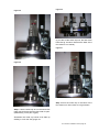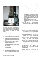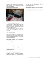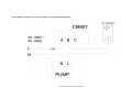
1
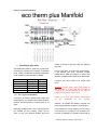
eco hometec
ecotherm underfloor heating
For that feeling of comfort!!
INSTALLATION &
USER MANUAL
eco hometec
Unit 11E
Carcroft Enterprise Park
Carcroft
Doncaster
DN6 8DD
Tel. 01302 722266
Fax. 01302 728634
e.mail. [email protected]
http://www.eco-hometec.co.uk
C:\Users\tim.bartlett\Documents\Marketing Backup\Manuals Various\underfloor heating1 files\Final
Protected Versions\eco hometec new build installation manual Nov 2008 Emetti MF & ICMA BV.doc\
eco hometec has a policy of continuous improvement and reserves the right to change any specification
without notice. Your statutory rights are not affected.
14 1 Filling & Pressurising the system 16 Pre-installation requirements 4 1.13 Opening Flow Meters 16 1.1 Screed Subfloor 4 1.2 Moisture barrier 4 1.3 Edge insulation strips 5 1.4 Expansion joints 5 2 Flooring screed 5 1.5 Flooring screed 5 1.6 Heat insulation 5 1.7 Floor irregularities 6 1.8 Pressure testing 6 1.9 Placing and Fixing the Manifold 6 1.10 eco hometec manifold 6 3 15 Filling the system 18 16 Pressurising the system 18 17 Starting up your system 19 1.14 Structural concrete: 19 1.15 Screed floors 19 1.16 Dry biscuit screed for timber floors 19 1.17 Anhydrite floor 22 18 Commissioning the System 22 19 Additives & Inhibitors 22 Distribution pipe work 7 1.11 Floor Types and Suitability 7 4 Installing the UFH pipe work 8 5 Installing Blue templates 10 6 Grip rails 11 20 Floor Finishes Suitable for Floor
Heating 22 21 How to run your floor Heating System
– using Setback. 23 1.18 With the System Control unit. 23 1.12 Tacker Gun 12 7 Manual Stapling By Hand 12 8 Wood floors on solid floors 12 9 Timber suspended ground floor. 13 10 Restrictions on Floor Depths 13 11 Suspended 1st & 2nd Floors. 14 1.19 Suggested operation 23 22 Maintenance 23 23 23 Fault finding: First check the following 24 Problem Solving 25 Figure 24 Placing and Fixing the Manifold 15 12 Fixing the manifold 15 13 Connecting pipes to manifold 15 underfloor heating1 new build installationl manual page 3
1
7. Make sure you fit the expansion edge
insulation strips.
Pre-installation requirements
8. Please check you have been delivered
all components to complete installation
in accordance with these instructions.
Check your order corresponds with
1. Your invoice
9. Make sure the system is filled in line
with instructions and pressure tested to
6bar before the floors are put down.
This procedure not only ensures the
system is watertight but helps to
maintain the pipe shape during the
screeding process.
2. Your CAD drawing and pipe schedule
(this is to optimize roll lengths and will
tell you which circuit to take of which
roll).
3. Check you have the appropriate fixings
for the installation & insulation
4. Check
your
floor
construction
corresponds with the CAD drawing &
fixings
Prior to the beginning of installation work,
windows and doors should be in place and
interior walls finished in order to ensure correct
location of pipework
The installation of this equipment should be
carried out by a competent person and in
accordance with the relevant, Building
Regulations, Model Water Bylaws and the
Building Standards (Scotland) Regulations.
eco hometec shall not be responsible for any
damage or loss resulting from failure to carefully
observe the instructions given.
The subfloor must be clearly swept and free of
mortar residues before eco hometec system
boards are put in place, to ensure that moulded
floor templates lie evenly on the subfloor. Other
trades should be excluded until installation is
completed.
1.1
Installers should read this manual carefully.
Responsibility for finished system function
and operation rests with the installer.
Please pay attention to the following points.
1. Make sure you understand the design
and pay careful attention to pipe
spacing.
2. Where pipes pass through walls they
must be sleeved.
3. The CAD drawing supplied contains
information on pipe centres and pipe run
lengths read it.
4. Please ensure all timber joist notching
complies with building regulations.
5. The software calculates the total amount
of pipe required to complete the
installation.
Please make sure you
optimise pipe supplied by calculating –
before cutting – optimum lengths to be
cut from each roll – please see CAD for
cutting list.
6. eco hometec accept no responsibility
for
pipe shortages as a result of
mistakes or failure to optimise pipe
cutting.
eco hometec installation manual page 4
Screed Subfloor
The subfloor below the floor heating system
must not contain joints, steps or cracks, etc.
The working surface of the screed subfloor
should be swept clean and be free of surface
irregularities, mortar residues, pipes and pipe
slots. Only under these conditions is a uniform
flooring construction ensured.
1.2
Moisture barrier
A moisture barrier may be required for
basements or cellars. The barrier protects
against ascending and lateral moisture. In all
cases, the decision to install a moisture barrier
depends on the particular construction
circumstances and should be made on a caseby-case basis.
The sealing of building components should then
be carried out.
If using Polystyrene floor
insulation in selecting materials it should be
ensured that only solvent-free polystyrene
compatible materials are used. Compatibility
with styrofoam is an absolute requirement.
Tarred cardboard, etc. or patching and sealing
substances containing solvents may not be
used.
Best suited for such purposes are
asphalt-coated sealing tapes and plastic foils.
Abutments should be overlapped and heatsealed.
1.3
Edge insulation strips
Edge insulation strips permit the free expansion
of flooring screed and prevents the transmission
of impact sound to adjacent walls. The edge
insulation strips must extend from the subfloor to
the upper edge of the flooring layer and allow at
least 5mm for movement of the flooring screed.
The eco hometec edge insulation should be
applied against all ascending construction
elements such as walls, door frames or
columns.
1.4
Expansion joints
IMPORTANT: No single area of screed should
exceed 40m2. Edging strip to form an expansion
joint should separate areas greater than this.
Create expansion joints by inserting a section of
edge insulation strip between two system
boards.
Figure 1 Expansion joints
2
Flooring screed
Standard flooring screed (1:4 with fibres is
recommended) can be applied over eco
hometec floor heating systems.
The thickness of concrete layers used in the
various constructions corresponds to the
stability category specified for residential
buildings. In most cases, a layer of 70mm
(50mm above the upper pipe surface) is
appropriate for direct embedding of the system.
For flooring screed subject to increased stress
and strain, e.g. warehouses, workshops, etc.,
flooring screed thicknesses are to be adjusted
upwards according to actual static conditions.
Depending upon the intended use, a special
construction configuration may be required.
Anhydrite concretes containing anhydrite
binders as specified in DIN 4208 have no
negative effect on floor heating system
components.
The low heat conduction factor should be taken
into account, however. When using anhydrite
concrete, appropriate insulation should be
applied to protect against inflowing concrete.
1.5
Flooring screed
Aggregate: gravel sand 0/8mm
Mixture: cement :aggregates = 1:4 + fibres By
weight (50kg cement = 225kg sand = approx.
26-28 shovels) + fibres.
+ 16-18 litre water to mix it
(water quantity depends on moisture content of
sand)
1.6
Joints are to be placed:
•
above existing building expansion joints
at corresponding positions and in
matching lengths
•
as field borders
•
as edge joints against all adjacent
building elements and built-in fixtures
Both flow and return pipes are run through the
screed expansion joint and sleeved 400mm
minimum either side.
Heat insulation
eco hometec UFCH can be permanently built
into solid concrete or screeded floors. Insulation
is built into the floor as required by current
Building Regulations.
IMPORTANT: Insulation thickness to comply
with local building regulations and to
satisfaction of Building Inspectors.
underfloor heating1 installation manual page 5
1.7
Floor irregularities
Where piping has already been installed on a
subfloors prior to system board installation, a
compensation layer of styrofoam can be laid to
provide a level surface on which to place the
system boards.
System boards GTFN-F and GTFN-D can be cut
with a profile cutter to fit over existing piping
segments - a cost-effective alternative to the
construction of a compensation layer. In no
case, however, should granular fillers (e.g.
sand) be used to build a compensation layer, as
they are subject to hollowing, which can easily
cause damage to pipe systems.
1.8
Pressure testing
A test of heating system seal is performed at a
pressure of 4bar before flooring screed is
poured. This pressure is to be maintained until
screed application is completed in order to
ensure that any leaks are identified immediately.
1.9
Placing and Fixing the Manifold
Place & install the manifold according to your
CAD drawing
eco hometec installation manual page 6
Although the control unit/ manifold has a built-in
pump with a low noise level, we advise not to
install the unit close to a bed, in a bedroom or
behind a timber partition wall. Any noise could
be increased due to the “sound box” effect
created by the timber partitioning. The manifold
should be fixed level and approximately 600mm
above the finished floor.Ample space should be
given to the manifold in order that the unit and
pump can be serviced in the future.
1.10
eco hometec manifold
Designed for ease of installation and to take up
minimum wall space the eco hometec manifold
offers the following benefits.
1. Flow & return temperature gauges.
2. Fixing kit.
3. Automatic air vents
4. Flow meters
5. Isolating valves
Figure 2 eco hometec manifold
3
means of fixing to the floor and the underlay
they use.
Distribution pipe work
The table below offers a guide only to pipe work
and sizing according to the number of manifold
ports. Extra consideration should be made if the
route includes excessive bends or fittings.
Ports/Circuits
2–7
2–7
8 - 10
8 - 10
11 - 20
1.11
F & R Length
<14m
>14m
<4m
>4m
Pipe Dia.
22mm
28mm
22mm
28mm
28mm
If this is too thick, (it should not exceed 2mm),
it will insulate your floor. Concrete, screed,
natural stone, slate and ceramic or quarry tiles
all allow excellent heat transfer and heat output.
Linoleum and Vinyl must be no thicker than
5mm.
Important: ensure when gluing Lino/Amtigo to
the concrete or screed that the concrete or
screed is dry and all moisture is out. Get the
heating running to dry out the floor.
Floor Types and Suitability
To ensure & achieve optimal heat output and
temperatures, you require good contact between
the floor structure and floor covering with no air
gaps.
Generally speaking thick cork & soft woods are
not suitable for floor heating. Watch out for
some of the new laminate boards and their
Failing to do this could cause condensation
on
the
underside
of
the
flooring.
Carpets - All carpets are suitable, however, the
total carpet thickness should not exceed 12mm.
If the carpet has a foam backing it must not be
more than 3mm. Underlay is not necessary, the
function of Underlay is to prevent wear & tear on
underfloor heating1 installation manual page 7
the underside of the carpet, however usually a
thinner, cheaper type is used - approx 3mm with
no air pockets.
The carpet can be laid loose, tensioned or glued
to
the
floor.
Chipboard, Ply, Wood, Laminate flooring - good
contact with the floor is essential, avoiding air
gaps, membranes for laminate flooring, must not
be thicker than 2mm with no air pockets. Start
up the heating to dry out the concrete or screed
- ensure the concrete or screed is dry with all
moisture out prior to applying any wood finish.
Hardwood flooring – wood should have a
moisture content of not higher than 10%.
The total wood thickness should not exceed
22mm, ensure the concrete or biscuit is dry and
all moisture is eliminated, prior to applying ANY
wood finish – start up the heating to dry out the
concrete or screed.
NB. with all floor coverings, laminates, tiles,
adhesives, grouts etc. check with the
manufacturer prior to installation to confirm their
suitability for use with under floor heating.
Carpets etc should not exceed TOG value of 1.
4
Installing the UFH pipe work
According to the floor construction method
specified the following types of fixings are
available.
1. eco hometec floor templates: Plastic
board with studs to clip the pipes in
between.
1. Plastic staples: Pipes stapled to an
insulation which has a woven or plastic
membrane attached to it.
2. Timber hammer clips: Plastic clips with
nail attached, for use with joisted floor
3. Clip rails: Plastic rail nailed through the
insulation on to the concrete floor by
means of a plastic nail in to a pre-drilled
8mm hole.
Identify and familiarise yourself with which
method you are using.
Make sure site is clear of water and debris, clear
any rubbish and sweep clean the entire area.
eco hometec under floor central heating can be
eco hometec installation manual page 8
permanently built into solid concrete or screed
floors. Insulation is either built either into or
layed onto the floor as required by current
Building Regulations.
The following instructions show how to
install your underfloor heating system on a
solid concrete or block and beam floor.
On a ground floor a minimum of 65mm foil
backed insulation should be laid on top of the
concrete slab or block and beam floor. The
damp proof membrane should be laid below the
concrete slab On a first floor a minimum of
30mm foil backed insulation should be laid on
top of the block and beam floor.
You only need another membrane above the
insulation if you are having a liquid screed
instead of a dry screed.
Ensure the insulation is laid flat and that there
are no gaps in the insulation.
IMPORTANT: Prior to installing the manifold or
any pipe you should have a clear understanding
of either the CAD drawing with pipe layouts or, if
you do not have a CAD, where you intend to fix
the pipes and at what pipe centres.
Tip
If installing without a CAD then draw out your
design on a piece of graph paper to a suitable
scale that fits your room. It is important that
pipes do not cross over and no circuit is greater
than 100m long. As a guide you will need pipe
at the following amounts.
a) 100mm centres 10m per 1m2
b) 150mm centres 6.7m per 1m2
c) 200mm centres 5m per 1m2
Mark your manifold position on the paper and
then draw in your circuit. Circuit patterns can be
form one of those below.
The pipe loops can be laid out in various
patterns however the optimum pipe layout is
normally achieved by mixing the flow and return
pipes so that the pipe with the highest flow
temperature is adjacent to the pipe with the
lowest return temperature. This is commonly
referred to as a reversed return or counter spiral
layout.
Examples of these patterns can be seen below:
Serpentine patterns allow for the hottest water to
border the exterior perimeter (highest heat loss
areas). The water temperature is highest at the
coldest walls and will decrease as it flows
through the pipe towards the centre of the
room.
Figure 3 Pipe patterns
Counter flow patterns differ from serpentine in
that the supply and return pipes are laid out next
to each other, creating an average temperature
between them.
Remember the following:
1. Pipes should be laid in a continuous
length.
2. The maximum circuit length is 100m.
3. Connections must not be made in the
area to be screeded.
4. Pipes must not cross over.
5. Do not forget to allow for connection
lengths back to the manifold in overall
circuit design and length.
6. If you area requires more than 100m
divide it in half and fit two circuits of
similar length.
EG. Room area 13m2
pipes at 100mm centres pipe required
130m. Fix with two circuits of 65m.
Figure 4 Installing the floor insulation
Install the foam expansion strip around the
entire perimeter of the area to be heated and
across door ways or openings. Fix the strip in
underfloor heating1 installation manual page 9
place by pushing black plastic staples through
the strip and into the floor insulation or by using
large head clout nails to fix the strip to the walls.
Figure 7 Fixing Blue templates
Figure 5 Fixing the edge insulation
Take the next template and position it on top of
the first one with the cut outs in the same
position and press into place.
IMPORTANT: If you are going to use a liquid
screed you need to use an expansion strip with
a thin polythene strip attached to it.
Figure 8 Overlapping templates
Figure 6 Edging strip for liquid and pumped
screeds
Fix the templates to the insulation using red
plastic nails or staples.
Figure 9 Securing down blue templates
This polythene strip must be taped to the
membrane that has been laid on top of the
insulation with specialist floor screed tape in
order to ensure a watertight seal.
5
Installing Blue templates
When fitting the blue templates lay the first one
in the right hand corner of the room with the cut
out at at the far top left corner the other cut out
will be diagonally opposite in the right hand
corner. This is important to ensure correct
interlocking of templates.
Take the next template and position it on top of
the first one with the cut outs in the same
position and press into place.
eco hometec installation manual page 10
When all the templates have been fitted the
heating pipe is simply 'walked in' in line with the
CAD or design and is then after pressurising
and testing is permanently covered by screed.
Figure 10 Walking in pipe
6
Grip rails
These should be fixed to floor insulation using
pipe staples 500mm apart and across the
planned pipe work direction.
Figure 11 Fixing grip rails
The ecotherm floor templates hold the pipe
against movement when screeding. Optimum
screed depth is 65mm from panel base.
IMPORTANT: If using pumped or self levelling
screed care must be taken to ensure all gaps
are sealed and no screed can get underneath
the templates or insulation. Failure to observe
this may lead to the templates floating on the
screed with must be avoided. Pouring the
screed from the middle is recommended as the
weight of screed helps to stop the floor from
floating.
IMPORTANT: No single area of screed should
exceed 40m2. Edging strip to form an expansion
joint should separate areas greater than this.
Create expansion joints by inserting a section of
edge insulation strip between two system
boards.
Both flow and return pipes are run through the
screed expansion joint and sleeved 400mm
minimum either side.
Figure 12 Pipe work should then be fixed into the
grip rails.
Use staples to fix pipes as they are turned to
hold them into place.
Figure 13 Fixing pipe turns
When fixing to grip rails keep the coil laid flat on
the floor and roll it out in front of you.
Alternatively, a second person can roll out the
pipe ahead of you whilst you fix the pipe.
underfloor heating1 installation manual page 11
Figure 14 Fixing pipe
1.12
Tacker Gun
If you are stapling the pipe directly to the
insulation with tacker gun load the gun with
staples.
Figure 16 Tacker clips
7
Manual Stapling By Hand
If you are stapling the pipe directly to the
insulation keep the coil laid flat on the floor and
roll it out in front of you.
Figure 15 Loading tacker gun
The staples should be placed over the pipe and
into insulation at a minimum of 500mm centres.
Space them as needed to hold the pipe firmly in
place when bending the pipe at circuit ends.
Alternatively, a second person can roll out the
pipe ahead of you whilst you staple it to the
insulation.
Figure 17 Hand stapling
8
Wood floors on solid floors
If installing a wood floor on top of a solid floor
then an alternative fixing method is to fix 100mm
timber supports to concrete sub floor at
400mmm centres. 50mm Kingspan or For these
type of floors we recommend fixing sterling or
equivalent boards to the underside of the joists.
Staples come in strips of 30 ready to load onto
dispenser.
eco hometec installation manual page 12
Figure 18 Floor design when fixing wooden floor
on concrete base.
The pipes are then fixed in line with the CAD
design to the insulation. Finally the sand and
cement mix 1:8 is installed between the joists
level with the underside of the finished floor.
Please note:
When installing under floor
heating in timber floors a large quantity of pipe
will need to pass across the joists.
The joists will require substantial notching and
this will inevitably weaken them.
Figure 19 Pipe layout between joists at 100mm
centres.
IMPORTANT: When calculating floor joist
dimensions do not forget to allow enough depth
to accommodate pipe work and notches.
Figure 20 Timber ground floors
Timber frame houses with suspended ground
floor installations will require an alternative
installation.
10 Restrictions on Floor Depths
9
Timber suspended ground floor.
For these type of floors we recommend fixing
sterling or equivalent boards to the underside of
the joists.
Next fix 25mm x 50mm battons down the length
of the joists so the top edge is 100mm lower
than the finished floor.
For installations with restrictions on floor depths
or
overall
ceiling
heights
then
eco
hometecoffers a dry system board with an
overall depth of 22mm. The system is suitable
for refurbishments or new constructions where
height restrictions apply and normal installation
methods are not possible.
Rockwool or equivalent insulation bats are laid
on top of the boarding between the joists to
finish level with the previously fixed battons.
This system is ideal for timber framed properties
or where structural restrictions do not allow the
loading of ceilings with a sand and cement
biscuit mix.
Next cut and lay 50mm Kingspan or equivalent
on top of the battons and above the Rockwool.
The system utilizes wood-fibre boards with a
thickness of 22 mm.
When fixing to joists and 600mm centres
additional timber support may be required if the
Rockwool is not compacted enough to support
the insulation properly.
There are two types of boards.
The first has routed grooves at 150mm centres
along the length of the board, the second one is
provided with routed wheels to enable the pipe
underfloor heating1 installation manual page 13
to be returned and installed according to the
CAD design.
Edge insulation is fixed around the perimeter
walls and the boards are simply laid and fixed
across the joists in line with the supplied CAD
and can be cut to shape with a standard wood
saw.
When calculating floor joist dimensions, allow
enough depth to accommodate the UFH pipe
work and notches.
Figure 22 Suspended Floor System joists at
400mm
The pipe is the fixed into the grooves in line with
the CAD drawings. To finish the installation and
to lock the pipes and boards in place the whole
system should be covered with 3mm hardboard
screwed to the plates.
Dimensions of both types of boards are identical
at 900/1350mm.
The thermal conductivity
coefficient of the heating board material is 0,1
W/mK, the specific gravity amounts to 750
kg/m3.
25mm of Kingspan or equivalent
insulation should be fitted beneath the system
boards.
The preferred method of installation and an
alternative to notching the joists is to install
on counter battons as in the diagram below.
Figure 23 System installed on top of existing
suspended first floor.
Figure 21 Dry system Boards
Check your CAD drawing for individual room
pipe centres.
Figure 29 below shows typical pipes layout with
pipes fitted between joists at 200mm centres.
11 Suspended 1st & 2nd Floors.
ecotherm UFCH can be installed simply
between the joists of a suspended floor.
However, in order to maximise the efficiency
and output we recommend laying a weak mix of
sand and cement around the pipes and between
the joists immediately under the finished floor.
This gives the floor extra thermal mass and
improves the overall output and performance of
your heating system.
IMPORTANT:
When installing under floor
heating in timber floors a large quantity of pipe
will need to pass across the joists.
The joists will require substantial notching and
this will inevitably weaken them.
eco hometec installation manual page 14
Figure 24 Placing and Fixing the Manifold
12 Fixing the manifold
Place & install the manifold according to your
CAD drawing.
Although the manifold has a pump with a low
noise level, we advise not to install the unit close
to a bed, in a bedroom or behind a timber
partition wall.
Any noise could be increased due to the “sound
box” effect created by the timber partitioning.
Generally the manifold is mounted 600mm
above the floor and should be level. It can be
mounted at a different height, upside down or on
a different floor to the one being heated.
Discuss this with your technician.
1. Once this area has been installed, the
pipe should be cut & connected to the
front valve of the manifold and labeled.
2. If the pipe length is longer than the
required area, several rooms may be
coming from 1x larger coil, the pipe itself
is clearly marked at every metre, to
allow you to check how much pipe has
been used.
3. Repeat the above until all ports have
been installed & connected to the
manifold.
Pipes passing through the screed and up to the
manifold should be sleeved 600mm either side.
Ample space should be given to the manifold in
order that the unit can be serviced in the future.
13 Connecting pipes to manifold
1. Pipes should be cut straight with a pipe
cutter.
2. Do not use a saw of any type.
3. Slide nut & compression ring over the
pipe & push hose pillar completely into
the pipe.
4. Push the hose pillar with euro cone into
the valve while holding the pipe, keep
pushing upwards until nut is tightened,
eco hometec installation manual page 15
tighten nut hand tight & turn 1 x further
turn with spanner.
5. DO NOT OVERTIGHTEN
6. Make sure pipes/ circuits are labeled
14 Filling & Pressurising the system
Figure 25 Filling & Pressurising
Figure 26 Flow meters
A test of heating system seal is performed at a
pressure of 6 bar before flooring screed is
poured. This pressure is to be maintained until
screed application is completed in order to
ensure that any leaks are identified immediately.
Step 1 Lift up the white cap so it covers the flow
gauge nut as in fig 29 below.
Figure 27 Lift up the white cap
System can be pressurized for testing purposes
with water.
REMEMBER: You must be extremely careful
to avoid frost unless anti freeze has been
added to the water.
Recommended anti freeze is Alphi 11 from
Fernox.
1.13
Opening Flow Meters
The following steps show how to open each port
to allow water to circulate through the system.
This is in addition to opening the blue turn
buttons on the top rack, (the return), of the
manifold.
eco hometec installation manual page 16
(If you take off the white cap completely, the flow
meter should look like the fig 30 below although
the flow gauge could have been unscrewed and
be in a higher position as shown in fig 31 below.
Figure 28
Figure 30
(If you take off the white cap now, the flow meter
looks like fig 33 below. Note that the base of the
flow meter is now raised.)
Figure 31
Figure 29
Step 3 Push the white cap to the base of the
flow meter so it clicks down as in fig 34 below.
Step 2 Use the white cap to turn the whole flow
meter anti-clockwise until the flow meter is open.
(Alternatively, use a pair of grips)
Remember the white cap needs to be lifted up
halfway to cover the flow gauge nut.
eco hometec installation manual page 17
Figure 32
9. Open first turn button (return rail) fully by
turning anti-clockwise.
10. Open flow meter valve on same circuit by
the following procedure:
Unclip white plastic flow meter cap from
metal base, (with the aid of a flat head
screwdriver), and lift up slightly.
Hold white cap over black plastic
hexagonal nut so top of white cap is
level with bottom of transparent section
of flow meter.
Turn white cap anti clockwise so black
nut and black plastic base of flow meter
valve turn with it. Flow meter valve will
move upwards and will open after about
five full turns.
Water will now flow through circuit.
Click white cap back down on its metal
base.
11. Air vent caps need to be unscrewed to
allow air to escape. Let water flow around
circuit until there is a continuous flow of
water through drain pipe with no air
bubbles.
You can now twist the flow gauge clockwise or
anti-clockwise which adjusts the flow rate when
the under floor heating system is in operation.
For the time being leave the flow adjuster about
halfway between the highest and lowest
position.
15 Filling the system
1. Close isolating valves on manifold
2. Connect suitable filling pipes to drain and
fill points.
3. Route pipe connected to drain point on
return rail of manifold to suitable discharge
spot.
4. Connect pipe from fill point on flow rail of
manifold to cold water supply.
5. All turn buttons (return rail) will be closed
as supplied. They can be closed by turning
them clockwise.
6. All flow meter valves (flow rail) will be
closed as supplied.
7. Turn on cold water supply at source.
8. Open valves on drain point and fill point by
turning in the direction indicated on the
valve.
eco hometec installation manual page 18
12. When circuit is full and vented adjust flow
meter by turning black nut clockwise until
red marker shows a reading of
approximately 2-3 L/min.
13. Close circuit by turning turn button (return
rail) clockwise as far as it will go. Flow of
water should stop immediately, if not, there
is still air left in pipe.
14. Repeat steps 9 to 13 for next circuit on
manifold until all circuits are filled and
vented.
15. Once all circuits are filled and vented,
open all turn buttons so that water is
flowing through all circuits.
16. Close valve on return rail drain point and
let pressure build for a few seconds before
closing valve on flow rail fill point.
16 Pressurising the system
Now that system is filled it needs to be
pressurised to 6bar in order to test that it is
completely sealed.
Pressurise system to 6 bar using a
Rothenberger pump or similar connected to the
fill point. Leave for 10 minutes. After this time
pressure should have dropped by no more than
1 or 2 bar.
If pressure drops significantly, check system for
leaks and make sure all connections are tight
but not over tightened.
Figure 33 Pressurising the system
you can raise the temperature to 250C &
increase daily by 100C.
Note: Cracking may occur, this is not important
as it is being covered any way
You can apply a stronger mix i.e. 4: 1 this will
allow contractors to walk over the screed without
it crumbling up. Prior to the wooden floor being
fixed.
17 Starting up your system
The system can be started without room stats
being connected, this is to allow a “drying out
period “ as long as the Regulating stat & safety
stat are fitted to the manifold
To accommodate this, power the boiler, &
system pump & manifold pump through the
safety stat.
1.14
Structural concrete:
If the pipes are fitted into a structural concrete
floor and is more than 4 weeks old, the system
can run @a temperature of 500C – this you set
using the regulating stat.
Boiler setting should be 700C & by pass @
manifold should be open, if the boiler is not of
the condensing type.
1.15
Screed floors
Screed floors should also be at least 4 weeks
old, however on initial start up, start off with
temperatures of 250C, then can be increase
every other day by 5C until 500C has been
reached, this slower process to avoid cracking &
curling of the screed.
1.16
Dry biscuit screed for timber floors
Dry biscuit screed for timber floors should be
allowed to dry naturally for 2- 3 days after which
eco hometec installation manual page 19
22mm Blending Valve for use with all manifolds up to and including 9 port
Dimensions
Description
Thermostatic blending valve available with 22mm
compression connections. RWC wax capsule technology
ensures stable mixed water temperature. Suitable for
blending the flow and return to achieve a stable system
temperature in underfloor heating systems up to 200
square metres.
22mm
130mm
Product Range
HEAT 219 058
22mm Compression
Performance
2.5
95mm
43mm
Pressure (Bar)
2
Specifications
1.5
1
0.5
0
0
10
20
30
40
50
60
70
Temperature setting range:
Flow supply temperature:
Return supply temperature:
Temperature stability:
Working pressure, static:
Working pressure, dynamic:
Flow rate (L/M)
Materials
Body:
Internal brass components:
Seals:
Spring:
Piston:
Fittings:
Cast gunmetal, nickel plated
DZR brass
Nitrile elastomer
Stainless steel
Polysulfone polymer
DZR brass
30°C to 60°C
85°C max.
5°C - 75°C
+ 2°C - 22mm
10 Bar max
6 Bar max.
0.2 Bar min.
How to Specify
Blending valve with 22mm compression connections for
underfloor heating systems up to 200 sq meters. (Select
appropriate range code).
Guarantee
All RWC products undergo strict performance tests prior to
despatch, and are guaranteed against faulty materials and
workmanship for one year from date of purchase. This is in
addition to any statutory rights.
Typical Installation
FLOW TO
MANIFOLDS
(OR LOOPS)
RELIANCE
HEATGUARD UFH
MIXING VALVE
CIRCULATING
PUMP
RETURN FROM
MANIFOLDS
(OR LOOPS)
ZONE
VALVE
ISOLATING
VALVES
Contacts:
Sales Enquiries
Telephone:
Fax:
E-Mail:
+44 (0)1386 712400 +44 (0)1386 47148
+44 (0)1386 47028
+44 (0)1386 422217
[email protected]
[email protected]
Technical Support
Reliance Water Controls
Worcester Road, Evesham,Worcestershire, WR11 4RA, UK
Tel: +44 (0)1386 47148 Fax: +44 (0)1386 47028 www.rwc.co.uk
HEATUFH-002-10/02 P2
RWC reserves the right to make changes to the product which may affect the accuracy of information contained in this leaflet
© Reliance Water Controls, Oct 2002
28mm Blending Valve for use with 10,11 and 12 port manifolds
Dimensions
Description
Thermostatic blending valve available with 28mm
compression connections. RWC wax capsule technology
ensures stable mixed water temperature. Suitable for
blending the flow and return to achieve a stable system
temperature in underfloor heating systems up to 300
square metres.
28mm
146
Product Range
HEAT 115 002
28mm Compression
Performance
139
57
All dimensions in mm unless stated
Pressure Loss (Bar)
2.5
Specifications
2.0
Temperature setting range:
Flow supply temperature:
Return supply temperature:
Temperature stability:
Working pressure, static:
Working pressure, dynamic:
1.5
1.0
0.5
0
1
2
3
Flow (m3/h)
4
6
5
Ambient to 60°C
85°C max.
5°C - 75°C
+ 3°C
16 Bar max
6 Bar max.
0.2 Bar min.
How to Specify
Materials
Body:
Internal brass components:
Seals:
Spring:
Piston:
Fittings:
Cast gunmetal
DZR brass
Nitrile elastomer
Stainless steel
Polysulfone polymer
DZR brass
Typical Installation
Blending valve with adjustable temperature indicated on
the cap and 28mm compression connections for underfloor
heating systems up to 300 sq meters. (Select appropriate
range code).
Guarantee
All RWC products undergo strict performance tests prior to
despatch, and are guaranteed against faulty materials and
workmanship for one year from date of purchase. This is in
addition to any statutory rights.
FLOW TO
MANIFOLDS
(OR LOOPS)
RELIANCE
HEATGUARD UFH
MIXING VALVE
CIRCULATING
PUMP
RETURN FROM
MANIFOLDS
(OR LOOPS)
ZONE
VALVE
ISOLATING
VALVES
Contacts:
Sales Enquiries
Telephone:
Fax:
E-Mail:
+44 (0)1386 712400 +44 (0)1386 47148
+44 (0)1386 47028
+44 (0)1386 422217
[email protected]
[email protected]
Technical Support
Reliance Water Controls
Worcester Road, Evesham,Worcestershire, WR11 4RA, UK
Tel: +44 (0)1386 47148 Fax: +44 (0)1386 47028 www.rwc.co.uk
UFH28-001-10/02 P2
RWC reserves the right to make changes to the product which may affect the accuracy of information contained in this leaflet
© Reliance Water Controls, Oct 2002
1.17
refer to CAD drawing. If temperature is
to low boiler may need adjusting.
Anhydrite floor
19 Additives & Inhibitors
Anhydrite floor should be left dry naturally for 10
days, after which the temperature can be set to
300C & stepped up 100C each following week to
an absolute maximum running temperature 50600C.
IMPORTANT: If higher temperatures are used,
the water molecules within the screed will
evaporate and the screed will turn to powder
dust.
18 Commissioning the System
1. Confirm that the pipe stat is fitted at this
final stage and check that all flow
meters are opened 1 turn.
The following additives have been approved for
the system and will not invalidate your
guarantee.
They are all Fernox Products called
1. MB 1 – Inhibitor
2. Cupinol - Inhibitor
3. Alphi 11 – Inhibitor & Antifreeze
If you live in an area with exposure to severe
frost or leave the property unattended in the
winter, we recommend you use Alphi 11 – a
combined Inhibitor & Antifreeze
See the product details for quantity required.
2. Switch the programmer to manual and
ensure that it is calling for heat.
3. There should be no actuators fitted on
this circuit, the manifold should pump
should run and the zone valve should
open.
4. The boiler should fire up.
5. Disconnect all actuators from
manifold starting with zone 1.
the
6. Turn the zone 1 room stat fully up.
7. After 3 minutes the actuator should
open
and
the
plastic
window
background display should change to
red.
8. Fit the actuator to the appropriate valve
on the manifold (on large floor areas
there may be more than 1 actuator
check CAD).
9. Now turn off zone one and activate zone
two it is important to work methodically
like this to ensure that the correct room
stat is operating the appropriate
actuator.
10. Repeat process until all actuators are
checked.
11. Check system pressure is @ 1.5 bar &
no further air is coming out of air vents.
12. Check that the temperature on the flow
gauge reaches the required temperature
eco hometec installation manual page 22
For your calculation, each group/zone on your
system represents approx 12.5 litres of water.
20 Floor Finishes Suitable for Floor
Heating
Generally speaking to ensure & achieve optimal
heat output, you require good contact with no air
gaps.
Cork & new soft woods are not suitable for floor
heating. Watch out for ome of the new laminate
boards, their means of fixing to the floor & foam
membranes used.
Foam membranes should be kept to the
absolute minimum i.e. not more than 2mm
Any stone finish, concrete, screed, natural
stone, ceramic, quarry tiles or slate allows
excellent heat transfer.
Linoleum etc. Amtigo and other vinyl types are
all suitable –
IMPORTANT: ensure when gluing to the
concrete or screed that the concrete or screed is
dry and all moisture is removed – the heating
should have run for a sustained period of time to
ensure the concrete /screed is dry, failing to do
this, could cause condensation on the underside
of the flooring & consequential “bubbling” or
delaminating.
Carpets (including underlay) should not exceed
12mm, this can be laid directly on 19mm
chipboard flooring, if using a suspended, timber
joist system or directly on to the concrete floor.
If the carpet has a foam back this must not be
more than 3mm.
Underlay is not necessary - the function of
underlay nowadays is to protect the underside of
your carpet from wear & tear. Normally a
thinner, cheaper type is used - approx 3mm.
The carpet can be then laid loose, tensioned or
even glued to the floor. When glued the heat
output is higher.
Wood Finish: Hardwood flooring or Laminates
Good contact is essential, avoiding air gaps.
Moisture content of hardwood must not exceed
10%
The total thickness should not exceed 22mm.
Ensure the concrete or biscuit is dry and
moisture has been removed prior to applying
any wood.
Failing to do so can lead to condensation under
the wood which in turn will make the wood
expand.
21 How to run your floor Heating
System – using Setback.
The system is designed to provide heat at the
temperature requested by the room stat when
the programmer is on. At other times the system
will maintain a background temperature, which
can be preset. This is called setback.
1.18
With the System Control unit.
The programmer provides power to the room
stats when the required heating program is on.
The room stats regulate the room to the required
temperature.
When the programmer is in the off state, for
instance when you are out during the day or
overnight, the setback room stat will override the
programmer and bring the system on if the
temperature where it is located falls below its
setting 160C is a typical setting for this.
The set back stat should be in a location that is
typical of the temperature of the house. Halls,
landings, dining rooms and living rooms are
good choice.
Airing cupboards, above the manifold or in boiler
rooms are not suitable for the stat location.
1.19
Suggested operation
For best results set your system to come on two
hours before getting up and to run down two
hours before going to bed.
Most Important ;
Remember – room stats are thermostats/
sensors, NOT ON & OFF buttons.
DO NOT adjust your room stats, more than a
degree or two at a time
Avoid dramatic swings from Low to High
settings – simply adjust +/- 10C to 20C
Chilly?
Simply turn the room stats up 10C – 20C.
Too warm?
Simply turn the thermostat down by only 10C –
20C.
Finally, once you are HAPPY and satisfied
with the temperatures/ settings - leave them
alone & forget about them….!!
22 Maintenance
Pressure on your system should be checked
regularly, this should be @ 1.5bar, if not top up
using filling loop.
23 Fault
finding: First check the
following
1. Ensure all back valves area open by
having the screw driver slot – vertical.
2. Ensure all front valves are open, by
removing white caps & thermal
actuators, check pin in valve moves
freely in & out.
eco hometec installation manual page 23
3. Ensure return valve to boiler is open, by
having screwdriver slot vertical
4. If regulating valve is low, this should be
set @ 500C - 700C.
5. Remove regulation valve & check if pin
on valve moves freely – in & out.
6. Reconnect regulation valve,
pump on manifold is running.
check
7. Check boiler pump is running.
8. If system is properly filled according to
instructions the flow temperature
(bottom temp gauge) should be higher
than return temperature (top temp
gauge) – the difference between the 2 x
temperatures should be approx 100C –
ONCE the system is up to temperature.
9. Please remember the Initial “warm up or
run in time in a concrete/screed floor is
approx 4 to 8 hours before it comes up
to temperature.
eco hometec installation manual page 24
24 Problem Solving
Symptons
Flow pipe gets hot, return stays cool, even after
many hours running, temperature on flow side not
increasing.
Flow & Return pipes both hot, but temperature on
floor low.
Pump not running, after being off for summer, floor
does not want to heat up, pump seized.
Room stat calling for heat, but no power to the
pump.
One room warm, other cold.
One room not getting warm.
Noise in system.
Room gets too warm.
Checks/Remedies
Insufficient flow from boiler to manifold turn up
speed of boiler pump.
Flow & return to manifold wrong way round or
manifold pump not running.
Switch off pump, remove chrome screw in centre of
pump, insert screw driver & turn shaft by hand to
free shaft, replace chrome screw and switch pump
back on.
Safety stat on the manifold locked out or faulty,orr
electrical connection problems.
Check correct thermal heads on correct manifold
ports.
Air lock – flush through. Back valve on this circuit
closed – open. Blockage or kink in pipes.
Rubber washers on manifold fixing points not fitted
or too tight. Manifold fitted on stub partition, acting
like sound box. Tension on copper flow & return
pipes.
Air in system – due to wrong filling
procedure
No thermostatic control. Not connected to correct
manifold port. Thermal head faulty/broken. Room
stat faulty/broken.
eco hometec installation manual page 25
Figure 34 Typical Wiring Schematic for multi room control with Danfoss wiring centre
eco hometec installation manual page 26
Figure 35 Wiring example when only using CM907, high limit thermostat and pump.
eco hometec installation manual page 27