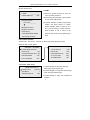
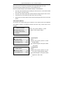
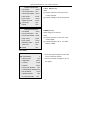
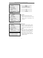
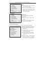
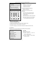
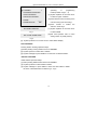
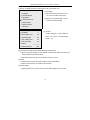
1
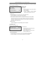
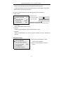
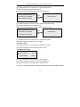
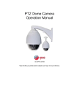
IR PTZ Dome Camera
Read this Manual carefully before installation and keep it for future reference.
Operation Manual of P T Z Dome Camera
Notice:
Precautions:
1.Non-techinician is forbidden to operate this dome device before
reading this manual thoroughly.
2.Cut the power supply off before operating the dome device to avoid
damage caused by improper operation.
3.Interior of the Dome device are precision optical and electrical device.
Heavy pressure, shock and other incorrect operations should be
prevented. Otherwise, may cause damage on product.
4.Please do not remove and disassemble any internal parts of Dome
video camera by self in order to avoid normal usage being impacted.
There is no part inside the device, which can be repaired by users
themselves.
5.All the wiring of the dome device should be conducted strictly
according to the wiring instruction. When necessary, thunder-proof,
surge-proof and other protecting measures should be carried out.
6.Please do not use the product under the situations of exceeding
specified temperature, humidity or power supply specifications.
1
Operation Manual of P T Z Dome Camera
Content
Chapter 1 Product Overview ...................................................................................... 4
1.1 Performance Instructions............................................................................ 4
1.2 Feature Functions Instruction..................................................................... 4
Chapter 2 Menu setting............................................................................................... 7
2.1 Operation instructions ................................................................................ 7
2.2 Main menu ................................................................................................. 7
2.3 Dome information ...................................................................................... 8
2.4 Display Options.......................................................................................... 8
2.4.1 Camera Name Setup............................................................................ 9
2.5 Control Options.......................................................................................... 9
2.5.1 Dome Addr Setup................................................................................ 9
2.5.2 Control Option Operation.................................................................. 10
2.6 Camera Options........................................................................................ 10
2.6.1 Zoom and Focus ................................................................................ 10
2.6.2 Camera Exposure ...............................................................................11
2.6.3 Others ................................................................................................ 13
2.7 Function Programming............................................................................. 14
2.7.1 Preset ................................................................................................. 14
2.7.2 Program VectorScan .......................................................................... 16
2.7.3 Pattern ............................................................................................... 17
2.7.4 Sector Setup ...................................................................................... 19
2.7.5 Mask Zone......................................................................................... 20
2.7.6 Mask Color........................................................................................ 20
2.7.7 Motion ............................................................................................... 21
2.8 System setup............................................................................................. 22
2.8.1 Clear Memory ................................................................................... 23
2.8.2 Restore Def Setting ........................................................................... 23
2.8.3 Color System..................................................................................... 23
2.8.4 Dome Reset ....................................................................................... 23
2.8.5 IR Module Setup ............................................................................... 23
2
Operation Manual of P T Z Dome Camera
Chapter 3 Short-cut Operations and Specification of Dome Device ............... 24
Chapter 4 Trouble Shooting of Dome Device ..................................................... 27
3
Operation Manual of P T Z Dome Camera
Chapter 1 Product Overview
1.1 Performance Instructions
¾
Address of Dome device is from 0~255. The number (address) of dome device in
the control system is setup by the hardware (8-digit on and off switch) of dome
device.
¾
Integrated multi-protocol and auto protocol differentiation. Note: The dome device
only auto differentiate controller of the first communication.
¾
Pan 360 degree continuous scanning.
¾
Tilt 90 degree action plus 2 degree angle adjustment. Plus the 2 degree
adjustment, the view angle can be 90 or 92 degree.
¾
Pan manual operation speed can be 0.1 to 150 degree per second.
¾
Tilt manual operation speed can be 0.1 to 55 degree per second.
¾
128 preset positions.(A fixed position that aimed by the dome camera, which can
be set and revised by user arbitrarily)
¾
The maximum running speed when preset position is being called can reach 240
degree per second with accuracy of ±0.1 degree.
¾
Compatible with many kinds of Module Camera.(Sony, Hitachi, Sanyo, Yoke, CNB,
LG, Haitron, Samsung, Dahua)
¾
Power supply: AC 24V/3A.
¾
Easy installation interface.
¾
Pass environmental protection grade IP66 (outdoor type).
¾
Adopts long distance RS-485 transmission mode.
Transmission speed, i.e. Baud rate is selectable. (2400bps/4800bps/9600bps
/19200bps).
1.2 Feature Functions Instruction
¾
English operation menu and function display.
¾
Camera name and operation position and angle display.(The name of the camera
can be edited and the coordinate angle of the dome device can be displayed on the
4
Operation Manual of P T Z Dome Camera
screen.)
¾
Operation crosshair function.(Enable this option, the target can be captured more
effectively with crosshair on the screen.)
¾
Three PTZ tours operation with 8 minutes record of each tour.(Can real-time
monitor and record the action of manual operation)
¾
Six group of programmable vector scans.(including scan speed, dwell time, preshot
and interruption between tours)
¾
Auto flip function with 10 degree move up.
¾
24 sectors of programmable sectional mask.(Can mask part of the sectors of
camera, which differs depending on different types of camera)
¾
8 sectors of programmable sectional display.(Can display the name and nature of
concrete position shooting by the camera)
¾
Auto enter function running after self-test of the dome device and auto enter
function running when there is no transmission.(Dwell time can be set from 5 to 999
seconds)
¾
Freeze video picture function.(frozen picture function)
¾
Operation return function.(after executing operation return, the dome device will
return to the previous operation)
¾
Intelligent manual scan function.(execute this function in manual pan operation, you
can adjust the manual pan operation)
¾
Intelligent power off real time memory.(If power is cut off when a certain function is
in operation, the dome device can resume working at where the power is cut off.)
¾
High efficient 3-dimension scan.
¾
Camera zoom in speed limit function.(When it is zooming in, the speed
of the dome device will auto slow down.)
¾
Remote setting of dome address.
¾
The world's most advanced high-power infrared lamp technology:
a. Infrared light power conversion efficiency, heat small, long life, low power, less
5
Operation Manual of P T Z Dome Camera
than 5 watts, Subversion of the traditional infrared lighting quick decline fatal
shortcoming
b. Use its power can be considered as a single point of light source characteristics,
developed a variable angle infrared light With the perspective of the size of the
change in one machine simultaneously follow the changes to ensure the infrared
light is neither wasted nor flashlight effect, to maximize the use of infrared light,
the subversion of the traditional large volume of long-range needs of the practice
of tens of watts
6
Operation Manual of P T Z Dome Camera
Chapter 2 Menu setting
2.1 Operation instructions
Menu operation instruction
To make a selection, move the joystick in the Up or Down direction. The on-screen
arrow points to the selected option. Using the joystick to the Left or Right position you
can change the value of your selection or enter the submenu for the selected option.
Press the button CLOSE on the keyboard controller to exit the menu or return to the
previous menu(one layer up)
Number setup.
¾
Joystick Left or Right when programming to select preset.
¾
Press OPEN to confirm, open and display the number selection cursor
¾
Joystick Left or Right to select the number to be entered
¾
Press OPEN to confirm selection. The selected number is displayed on the
corresponding data bit.
¾
Number of respective data bits are input as above.
¾
Press CLOSE to exit or return to the previous menu level when programming is
done.
2.2 Main menu
95+SHOT+ACK to enter the main menu of the dome as illustrated down.
TITLE
TITLE
1 LANGUAGE
ENGLISH
2 DOME INFORMATION
3 DISPLAY OPTIONS
4 CONTROL OPTIONS
5 CAMERA OPTIONS
6 FUNCTION PROGRAMMING
7 SYSTEM SETUP
The title may be different with different type
of dome.
1. Language Setup
Language: English.
2. Dome Information
Joystick down to move the cursor to press
OPEN or joystick left or right to move the
joystick to enter the menu.
3. Display Options
Display dome info or function.
7
Operation Manual of P T Z Dome Camera
4. Control Options
Set the pan or tilt and camera of the dome manually or auto compatible with the entire
control system. User individualized operation setting.
5.Camera Options
Set camera function.
6. Function Programming
Program and execute PTZ and VectorScan etc.
7. SYSTEM SETUP
System setup, Including, restore default setup clear memory, color system,
dome reset.
2.3 Dome information
Joystick down to move the cursor to press OPEN or joystick left or right to move the
joystick to enter the menu.
CAMERA
TITLE
TITLE
: xxxx
The title may be different with different type
PROTOCOL : xxxx
of dome.
BAUDRATE : xxxx
DOME ID
: xxx
VERSION
: xxx
IRIS CLOSE TO
Display camera type\ protocol\
baundrate\dome ID\ software version
EXIT
2.4 Display Options
Set the display of dome info or function.
Operation steps
DISPLAY OPTIONS
[1].Joystick up/down to move the cursor to
1 CAMERA NAME SETUP
2 COORDINATES
ON
3 START_UP SCR MSG
ON
4 CROSSHAIRS
ON
select Display Options
[2].Joystick left/right to enter Display Option
[3].Joystick up/down to select either one of the
sub-menu
[4].Joystick left/right to select ON/OFF
8
Operation Manual of P T Z Dome Camera
2.4.1 Camera Name Setup
Set the camera name
1.NAME
CAMERA NAME SETUP
1 NAME
___________
2 NAME DISPLAY
OFF
[1].Move the joystick up/down to move the
cursor to select the Name.
[2].Move the joystick left/right or press OPEN
to enter name editing menu.
PLEASE ENTER:
[3].Joystick left/right to select programming
WELCOME_________
position and press OPEN to confirm,
joystick left/right again to select( 0~9 or
ABCDEFGHIJKLN
A~Z ). Press OPEN to confirm selection.
OPQRSTUVWXYZ
Press CLOSE to exit or return to the
0123456789_
previous menu level when programming is
IRIS OPEN WHEN DONE
done.
IRIS CLOSE TO EXIT
2.5 Control Options
Set Auto Flip、Auto Focus、Auto AE, etc Move the joystick left/right or press
OPEN to enter control options
6 VECTORSCAN STILL OFF
CONTROL OPTIONS
1 DOME ADDR STETUP
7 AUTO FOCUS
OFF
OFF
2 AUTO FLIP
ON
8 AUTO AE
3 PROPORTIONAL SPD
ON
9 VECTORSCAN AF
OFF
4 PAN REVERSE
OFF
10 -2 TILT LIMIT
OFF
5 TILT REVERSE
OFF
11 SPEED LIMIT
OFF
2.5.1 Dome Addr Setup
1. Joystick left/right to setup the addr type.
DOME ADDR SETUP
1 ADDR TYPE
2 DOME ID
3 BROADCAST ID
PHYSIC
1
OFF
addr type through Physic/Logic.
2.Joystick left/right to change the dome ID(only
when addr type selects logic).
3.Joystick left/right to setup the broadcast ID
ON/OFF.
9
Operation Manual of P T Z Dome Camera
2.5.2 Control Option Operation
Move the cursor to select Auto Flip/Proportional Speed/Pan Reverse/ Tilt
Reverse/VectorScan Still/VectorScan AF/-2 Tilt Limit/Speed Limit.
Move the joystick left/right or press OPEN to Display on/off/PTZ/Z/OFF
¾
Auto Flip: If the camera lens auto rotates pan 180° then tilt 10° to auto track forward
when the lens goes down tilt 90°.
¾
Auto AE: If the camera is AE when the dome device changes its pan or tilt or zoom.
¾
VectorScan AF: If the camera AF when vector scan is running.
¾
Speed Limit: the moving speed of dome device matching the video ratio to lower the
speed.
2.6 Camera Options
As the dome can support many type of cameras, so the camera menu will be different
with different cameras, the following camera menu take Sony camera menu as an
example.
CAMERA OPTIONS
Move the joystick left/right or press
1 ZOOM AND FOCUS
OPEN to enter Camera options.
2 CAMERA EXPOSURE
3 OTHERS
2.6.1 Zoom and Focus
ZOOM AND FOCUS
1 ZOOM SPEED
2 DIGITAL ZOOM
3 AF SENSITIVITY
1. Zoom Speed
7
ON
Steps:
[1].Move the joystick up/down to select
HIGH
ZOOM SPEED.
[2]. Joystick left/right to setup the camera
ratio speed.
2. Digital Zoom
ZOOM AND FOCUS
1 ZOOM SPEED
2 DIGITAL ZOOM
3 AF SENSITIVITY
7
ON
HIGH
Steps:
[1].Move the joystick up/down to move
the cursor to select DIGITAL ZOOM.
[2].Joystick left/right to setup the camera
digital zoom ON or OFF.
10
Operation Manual of P T Z Dome Camera
3.AF Sensitivity
ZOOM AND FOCUS
1 ZOOM SPEED
2 DIGITAL ZOOM
3 AF SENSITIVITY
7
ON
Steps:
[1].Move the joystick up/down to move
the cursor to select AF Sensitivity.
HIGH
[2].Joystick
left/right
to
setup
AF
Sensitivity function of the camera
2.6.2 Camera Exposure
CAMERA EXPOSURE
1 AE MODE
AUTO
2 SLOW SHUTTER
OFF
3 SHUTTER SPEED
AUTO
4 IRIS LEVEL
AUTO
5 AGC LEVEL
AUTO
6 BRIGHT LEVEL
AUTO
7 SPOT AE
OFF
8 WDR
OFF
1.AE Mode
Steps:
[1].Move the joystick up/down to move
the cursor to select AE Mode.
[2].Joystick left/right to set up camera
in command of different switchover
(AUTO/MANUAL/IRIS etc.)
CAMERA EXPOSURE
1 AE MODE
AUTO
2. Slow Speed
2 SLOW SHUTTER
OFF
Steps:
3 SHUTTER SPEED
AUTO
[1].Joystick up/down to move the cursor
4 IRIS LEVEL
AUTO
5 AGC LEVEL
AUTO
6 BRIGHT LEVEL
AUTO
7 SPOT AE
OFF
8 WDR
OFF
to select SLOW SHUTTER.
[2].Joystick left/right to set up SLOW
SPEED ON or OFF.
11
Operation Manual of P T Z Dome Camera
3. Shutter Speed(Shutter Speed works
4. Iris (IRIS works under Manual/IRIS
under Manuel/Shutter MD)
MD)
Steps:
Steps:
[1].Joystick up/down to move the
cursor to select Shutter MD
[1].Joystick Up/Down to move the
[2].Joystick left/right to set up Shutter
[2].Joystick Left/right to set up the
cursor to select IRIS LEVEL
Speed
size of IRIS
CAMERA EXPOSURE
CAMERA EXPOSURE
1 AE MODE
AUTO
1 AE MODE
AUTO
2 SLOW SHUTTER
OFF
2 SLOW SHUTTER
OFF
3 SHUTTER SPEED
AUTO
3 SHUTTER SPEED
AUTO
4 IRIS LEVEL
AUTO
4 IRIS LEVEL
AUTO
5 AGC LEVEL
AUTO
5 AGC LEVEL
AUTO
6 BRIGHT LEVEL
AUTO
6 BRIGHT LEVEL
AUTO
7 SPOT AE
OFF
7 SPOT AE
OFF
8 WDR
OFF
8 WDR
OFF
(It
works
under
5. AGC Level(AGC Level works
6.
under Manual MD)
AUTO/MANUALMD)
Steps:
Steps:
[1].Joystick Up/Down to move the
[1].Joystick up/down to move the cursor to
Bright
level
select Bright level.
cursor to select AGC Level.
[2].Joystick left/right to set up Bright level.
[2].Joystick Left/right to set up the
value of AGC Level.
CAMERA EXPOSURE
CAMERA EXPOSURE
1 AE MODE
AUTO
1 AE MODE
AUTO
2 SLOW SHUTTER
OFF
2 SLOW SHUTTER
OFF
3 SHUTTER SPEED
AUTO
3 SHUTTER SPEED
AUTO
4 IRIS LEVEL
AUTO
4 IRIS LEVEL
AUTO
5 AGC LEVEL
AUTO
5 AGC LEVEL
AUTO
6 BRIGHT LEVEL
AUTO
6 BRIGHT LEVEL
AUTO
7 SPOT AE
OFF
7 SPOT AE
OFF
8 WDR
OFF
8 WDR
OFF
12
Operation Manual of P T Z Dome Camera
CAMERA EXPOSURE
1 AE MODE
AUTO
2 SLOW SHUTTER
OFF
3 SHUTTER SPEED
AUTO
4 IRIS LEVEL
AUTO
5 AGC LEVEL
AUTO
6 BRIGHT LEVEL
AUTO
7 SPOT AE
OFF
8 WDR
OFF
7.Spot
AE(OFF/ON)
Steps:
[1].Joystick Up/Down to move the cursor
to select Spot AE.
[2].Joystick Left/right to set up the Spot AE
CAMERA EXPOSURE
1 AE MODE
AUTO
2 SLOW SHUTTER
OFF
3 SHUTTER SPEED
AUTO
4 IRIS LEVEL
AUTO
5 AGC LEVEL
AUTO
6 BRIGHT LEVEL
AUTO
7 SPOT AE
OFF
8 WDR
OFF
8.WDR(OFF/ON)
Needs support from camera:
Steps:
[1].Joystick up/down to move the cursor
to select WDR.
[2].Joystick left/right to set up
the status
pattern of WDR.
2.6.3 Others
OTHERS
1 SHARPNESS
5
2 BACK LIGHT
OFF
3 WB MODE
AUTO
4 R GAIN
AUTO
5 B GAIN
AUTO
6 VERTICAL MIRROR
1. Move the joystick up/down to move the
cursor to select the options.
2. Move the joystick Left/Right to set up
the options.
OFF
7 HORIZONTAL MIRROR OFF
8 IR SW MODE
9 STABILIZATION
10 FUNCTION OSD
AUTO
OFF
ON
13
Operation Manual of P T Z Dome Camera
2.7 Function Programming
FUNCTION PROGRAMMING
Preset option
1 PRESET
1. Move the joystick left/right or press
2 VECTORSCAN
OPEN to enter Function Programming
3 PATTERN
options.
2. Move the joystick up/down to move the
4 SECTOR SETUP
cursor to select the preset options.
5 MASK ZONE
3. Move the joystick Left/Right or press
6 MASK COLOR
OPEN to enter preset options.
7 MOTION
2.7.1 Preset
1.Number
[1].Move the joystick left/right or press OPEN to enter the number editing programming.
PS: Program the number of preset position.
[2].Move the joystick left/right to select the number editing (numeral line 0~9),press
OPEN to confirm the selection. Press CLOSE to exit when your selection done.
PRESET
1 NUMBER
INPUT RANGE:
1
1~50
2 SET PRESET
001
3 CALL PRESET
0123456789
4 DELETE PRESET
5 NAME
64~77 102~165
____________
6 NAME DISPLAY
IRIS CLOSE WHEN DONE
OFF
2.Set Preset
[1].Move the cursor to select preset position.
[2].Move the joystick left/right or OPEN to enter the setting(ensure the preset position
data you desire to save)
[3].Press OPEN to finalize your selection, then the screen displays STORED and
return to the previous menu level. Or press CLOSE to return to the previous menu
14
Operation Manual of P T Z Dome Camera
level. without save your selection.
PRESET
1 NUMBER
1
2 SET PRESET
IRIS OPEN WHEN DONE
3 CALL PRESET
4 DELETE PRESET
5 NAME _____________
6 NAME DISPLAY
OFF
STORED
3.Call Preset
PRESET
1 NUMBER
1
2 SET PRESET
Call Preset
[1].Move the joystick left/right or press
OPEN. The lens auto switch to current
preset position corresponding to the
edited No.
3 CALL PRESET
4 DELETE PRESET
5 NAME
____________
6 NAME DISPLAY
OFF
4. Delete Preset
PRESET
Delete preset
1 NUMBER
1
[1].Program the desired deleting number
2 SET PRESET
referring to Number Setup Section so
3 CALL PRESET
as to select the preset position to be
4 DELETE PRESET
deleted.
5 NAME
_____________
6 NAME DISPLAY
OFF
[2].Move the cursor to select Delete
Preset Move the joystick left/right or
press OPEN to enter the Delete Preset.
ARE YOU SURE TO DO THIS?
[3].Press OPEN to confirm the selection
IRIS OPEN TO CONFIRM
and exit. Press CLOSE to cancel the
IRIS CLOSE TO CANCEL
selection and exit.
15
Operation Manual of P T Z Dome Camera
5. Name
PRESET
Name
1 NUMBER
1
2 SET PRESET
cursor to select the Name.
3 CALL PRESET
[2].Move the joystick left/right or press
4 DELETE PRESET
5 NAME
OPEN to enter name editing menu.
____________
6 NAME DISPLAY
[1].Move the joystick up/down to move the
OFF
(Please refer to name setting section of
Camera Name Setup)
6. NameDisplay
PRESET
NameDisplay
1 NUMBER
1
Setup On/Off display on the direction
2 SET PRESET
name preset.
3 CALL PRESET
[1].Move the cursor to select name
4 DELETE PRESET
5 NAME
display.
_____________
6 NAME DISPLAY
OFF
[2].Move the joystick left/right to set ON
or OFF of the name display.
2.7.2 Program VectorScan
Function: User can make different auto scan according to various inspection.
FUNCTION PROGRAMMING
1 PRESET
2 VECTORSCAN
3 PATTERN
4 SECTOR SETUP
5 MASK ZONE
6 MASK COLOR
7 MOTION
Programming VectorScan instruction
[1].Joystick Up/Down to select Program
VectorScan.
[2].Joystick Left/Right or press OPEN to
enter the programming.
[3].Joystick Up/Down to select pending
programming serial number(number
range:1~6).
[4].Move the Joystick
to select and enter
the items of Program a VectorScan
(items include:name/number/SP/dwell).
16
Operation Manual of P T Z Dome Camera
VECTORSCAN
1 NUMBER
I:Name
Pr:stands for Preset Position.
1
2 PROGRAM A VECTORSCAN
Vs:stands for VectorScan.
3 RUN A VECTORSCAN
Pt: stands for PTZ Tour.
4 DELETE A VECTORSCAN
II:Number Programming-selection
based on the name.
PROGRAM VECTORSCAN 1
NAME NUM
SP DWELL
III:SP-Set up the speed of Preset.
IV:Dwell
1.
Vectorscan running operation steps:
2.
I:Select pending Vectorscan track in
Number menu
3.
II:Joystick Up/Down to select Vectorscan
4.
III:Joystick Left/Right or press OPEN to
... ...
run the selected Vectorscan track
16.
IRIS CLOSE WHEN DONE
DELETE A VECTORSCAN
Vectorscan track deletion steps:
[1]:Select pending deleting vectorscan track in Number menu.
[2]:Joystick Up/Down to select Delete a VectorScan.
[3]:Joystick Left/Right or press OPEN to delete the selected vectorscan track.
2.7.3 Pattern
Function: User can program three traces simulating manual operation.
FUNCTION PROGRAMMING
1 PRESET
2 VECTORSCAN
3 PATTERN
4 SECTOR SETUP
5 MASK ZONE
PATTERN
Pattern Operation Steps:
[1].Joystick Up/Down to move the
cursor to select Pattern.
[2].Joystick Left/Right or press OPEN
to enter the menu.
6 MASK COLOR
7 MOTION
17
Operation Manual of P T Z Dome Camera
[3].Joystick Up/Down to select pending
PATTERN
1 NUMBER
operating
1
programming
Pattern(number range:1~3).
2 PROGRAM A PATTERN
[4].Joystick Up/Down to move the cursor
3 RUN A PATTERN
to select Program a Pattern.
4 DELETE A PATTERN
5 NAME
or
______
6 NAME DISPLAY
[5].Press OPEN to enter recording of the
manual running trace.as left Fig 1.
OFF
[6].Press
CLOSE
to
finalize
the
selection. as left Fig 2.
IRIS OPEN TO BEGIN
[7].Joystick Up/Down to move the cursor
to select NAME.
Fig 1
IRIS CLOSE WHEN DONE
[8].Edit name (Please refer to name
setting section of preset position)
Fig 2
[9]. Joystick Up/Down to move the cursor to select Name Display.
RUN A PATTERN
Running Pattern Tracking Operation Steps:
[1].Select pending running Pattern trace from NUMBER.
[2].Joystick Up/Down to select Run a Pattern.
[3].Joystick Left/Right or press OPEN to run the trace of selected Pattern.
DELETE A PATTERN
Delete Pattern Operation Steps:
[1].Select pending Delete Pattern trace from NUMBER.
[2].Joystick Up/Down to select Delete a Pattern.
[3].Joystick Left/Right or press OPEN to enter and Click OPEN to delete
the trace of selected Pattern as below Fig 3~Fig 4
18
Operation Manual of P T Z Dome Camera
2.7.4 Sector Setup
Function: To display the sector name when dome in the setted area
FUNCTION PROGRAMMING
1 PRESET
Sector Setup:
[1].Move the joystick up/down to move
2 VECTORSCAN
the cursor to select sector setup.
3 PATTERN
[2].Move the joystick left/right or press
4 SECTOR SETUP
OPEN to enter the setting.
5 MASK ZONE
6 MASK COLOR
7 MOTION
SECTOR SETUP
1 NUMBER
1
2 PAN START POS
0.0
3 PAN END POS
0.0
4 TILT START POS
0.0
5 TILT END POS
0.0
6 NAME
7 NAME DISPLAY
[1]. Number
Joystick left/right or press OPEN to
select the sector number(number
range:1~8).
________
OFF
[2].Pan Start POS \Pan End POS\Tilt Start POS\ Tilt End POS
⑴.Move the joystick left/right or press OPEN to select a Pan Start Point \Pan End
Point\ Tilt Start Point\ Tilt End Point.
⑵.IRIS OPEN when done or press CLOSE to exit but not save.
[3].Name
⑴.Select the sector name and press OPEN to enter name editing.
⑵.Edit the name referring to preset setup instruction.
[4].Name Display
Joystick Up/Down to move the cursor to select Name Display of ON or OFF.
19
Operation Manual of P T Z Dome Camera
2.7.5 Mask Zone
Function: User can protect the partial area by mask setting from the whole monitoring
area according to the situation.
MASK ZONE
1 NUMBER
MASK ZONE
1
2 MASK EDIT
3 MASK DISPLAY
[1].Number
⑴.Joystick Up/Down to move the cursor to
OFF
select NUMBER.
⑵.Joystick Left/Right to select pending
editing mask areas(from area1-24).
[2].Mask Edit
⑴.Joystick Up/Down to move the cursor to select Mask Zone.
⑵.Joystick Left/Right or press OPEN to enter editing.
⑶.Press OPEN to edit the mask zone, capture the mask point. Press NEAR,
FAR (set the mask area in pan action), WIDE, TELE (set the mask area in
tilt action) to adjust the area of mask zone. Press CLOSE to exit when done
and return to upper stage menu.
[3].Mask Display
Joystick Left/Right to set up the display name of ON/OFF.
2.7.6 Mask Color
Function: set the mask color.
MASK COLOR
1 MASK COLOR
GRAY5
2 SEMI-TRANSPARENCY OFF
[1]. Mask color
⑴. Joystick Up/Down to move the cursor
to select MASK COLOR.
⑵.Joystick Left/Right to move the cursor
to select the Mask color.
[2]. Semi-transparency
⑴.Joystick Up/Down to move the cursor to select SEMI-TRANSPAREN.
⑵.Joystick Left/Right to set up the Semi-transparency of ON/OFF.
20
Operation Manual of P T Z Dome Camera
2.7.7 Motion
MOTION
MOTION
[1].Move the joystick left/right or press
1 PARK ACTION
OPEN to enter sub-menu.
2 POWER ON ACTION
[2].The menu of “AUTO TRACK SETUP”
3 LIMIT OPERATION
is invalid.
4 AUTO TRACK SETUP <NA>
Park action function
PARK ACTION
1 ACTION
The lens will auto return to the assigned
NONE
2 NUMBER
preset position or perform certain motion
1
3 PARK TIME
using command set by user when the
120SEC
camera does not receive orders from
controlling device.
[1].Move the joystick left/right or press OPEN to enter the PARK ACTION.
⑴.Action
Ⅰ.Move the joystick left/right or press OPEN to enter the Action panel.
Ⅱ.Joystick left/right to select Action. Action by None/Preset/VectorScan/
Pattern/PanScan/AutoScan.
⑵.Number
Ⅰ.Select the Number and press OPEN or move the joystick left/right to enter
Number editing.
Ⅱ. Setup method: referring to preset setup instruction.
⑶.Park Time
Ⅰ.Select the Park Time and press OPEN or move the joystick left/right to enter
Park Time (time range:1-999).
Ⅱ.Setup method: referring to preset setup instruction.
[2].Select the Power on Action and
POWER ON ACTION
1 ACTION
2 NUMBER
VECTORSCAN
move the joystick left/right or press
1
OPEN to enter the Power on Action.
21
Operation Manual of P T Z Dome Camera
⑴. Select the Action and move the joystick left/right or press OPEN to enter Action.
Actionincludes:None/Preset/VectorScan/Pattern/PanScan/AutoScan
⑵.Select the Number and move the joystick left/right or press OPEN to enter. Setup
method: refer to preset setup instruction.
[3]. Move the joystick left/right or press OPEN to enter the Limit Operation.
⑴.Start Position
Move the joystick
LIMIT OPERATION
1 START POSITION
0.0
2 END POSITION
0.0
3 DIRECTION
RIGHT
4 OPERATION
OFF
left/right or press OPEN
IRIS OPEN WHEN DONE
Press open to save and exit, or press close to exit
⑵. End Position
Refer to Start Position setting section.
⑶.Direction
Move the joystick left/right to select the Direction(left or right).
⑷.Operation
Select the OPERATION and move the joystick left/right set up the Operation of
ON/OFF.
2.8 System setup
PARK ACTION
[1].Move the joystick left/right or press
1 CLEAR MEMORY
OPEN to enter submenu.
2 RESTOR DEF SETTING
3 COLOR SYSTEM
NTSC
[2].Move Joystick left/right to setup the
options.
4 DOME RESET
5 IR MODULE SETUP
22
Operation Manual of P T Z Dome Camera
2.8.1 Clear Memory
[1].Joystick Up/Down to move the cursor to select Clear Memory.
[2].Joystick Left/Right or press OPEN to enter.
[3].Press OPEN to Clear Memory or press CLOSE to cancel.
ARE YOU SURE TO DO THIS
IRIS OPEN TO CONFIRM
IRIS CLOSE TO CANCEL
Press
OPEN
PLEASE WAIT...
2.8.2 Restore Def Setting
[1].Joystick Up/Down to move the cursor to select Restore Def Setting.
[2].Joystick Left/Right or press OPEN to enter.
[3].Press OPEN to Restore Def Setting or press CLOSE to cancel.
ARE YOU SURE TO DO THIS
IRIS OPEN TO CONFIRM
IRIS CLOSE TO CANCEL
Press
OPEN
PLEASE WAIT...
2.8.3 Color System
[1].Joystick Up/Down to move the cursor to select Color System.
[2].Joystick Left/Right to select the PAL or NTSC.
2.8.4 Dome Reset
[1].Joystick Up/Down to move the cursor to select Dome Reset.
[2].Joystick Left/Right or press OPEN to reset the dome.
2.8.5 IR Module Setup
IR MODULE SETUP
1 IR CONTROL
AUTO
2 IR SW DELAY
10SEC
[1].Joystick Up/Down to move the cursor to IR CONTROL.
[2].Joystick Left/Right to select the IR control AUTO/ON/OFF.
[3].Joystick Up/Down to move the cursor to IR SW DELAY.
[4].Joystick Left/Right to select the IR Switch delay 5SEC/10SEC/15SEC/30SEC/45SEC.
23
Operation Manual of P T Z Dome Camera
Chapter 3
Short-cut Operations and Specification of Dome
Device
1.Short-cut operation table
Number
of preset
Control Object
position
position
Record line
51
52
Call preset
scanning speed
Pan-Tilt Control
Save preset position
Run cruise track
Start line
Set line scanning starting
scanning
point
Set line scanning ending
53
point
Background light
On
Off
Day/Night*
Auto
Color
Camera related
Camera menu
Camera function OSD
OSD*
On\Off
On\Off
58
Digital zoom*
On
Off
59
Focus*
Auto
Manual
60
Iris*
Auto
Manual
Auto
Manual
Indoor
Outdoor
ATW
One push WB
Long distance
Short distance
55
56
57
compensation*
61
62
White balance*
63
79
Set line scanning
mode
80
81
Run pattern 1
Run pattern
82
83
Run pattern 2
Run pattern 3
Run vector
Run vectorscan 1
84
Run vectorscan 2
85
Run vectorscan 3
86
Run vectorscan 4
24
Operation Manual of P T Z Dome Camera
87
Run vectorscan 5
88
Run vectorscan 6
89
Picture freeze*
On
Dynamic preset
Call dynamic
point
preset point
94
Dome reset
Reset dome
95
Main menu
Call main menu
96
Set the auto flip
On
91
101
Pan continuous
Off
Off
On
scanning
Notes:
1.These functions differs depending on different types of camera.
Description of the preset point:
Preset point of the position: 1~50, 64~77,102~165 (totally 128)
Function short-cut preset point: 51~63, 78~101
Note: Dome operation will be different due to controller’s different specs.
Preset point setting:
Press “No.” + “Shot” + “ON” .
Call Preset point:
Press “No.” + “Shot” + “ACK”.
Clear Preset point:
Press “No.” + “Shot” + “OFF”.
2. Description of “cruise track” function:
¾ When enter “51+SHOT+ON”, the device is enabled system default cruise track. The
device will auto scan point by point from No.1 preset position to No.16 preset position.
If certain position has not been preset or been cleared after preset, “cruise track” will
not scan them.
¾ Dwell time of the preset position is 2 seconds.
¾ About other 6 cruise tracks operation, please refer operation manual of the keyboard
controller. Different controller is with different operation.
25
Operation Manual of P T Z Dome Camera
3. Description of “Line-Scanning” function:
¾
Dome device will auto line-scan between two specified points.
¾
User can set the start point by “52+SHOT+ON” and end point by “53+SHOT+ON”.
¾
Line scanning speed set: user keep a manual line scan speed three seconds above,
then
through“51+SHOT+ACK”
to
save
the
speed
as
line
scan
speed,
use“52+SHOT+ACK” to enable the line scan.
¾
Dwell time of line-scanning between “starting point” and “ending point” is 2 seconds.
4. Intelligent manually pan continuous scan:
¾
When user use joystick for pan scan monitoring, keep manually 3 seconds, then
press“101+SHOT+ACK”, the dome can go on with the scan speed and monitor
position automatically .
26
Operation Manual of P T Z Dome Camera
Chapter 4
Trouble Shooting of Dome Device
1.Problem description: After power on without any response, not lock motor nor
images.
Possible reason: The power circuit maybe have some problem
Solution: Check the power cable is connected to power of AC24V.
2. Problem description: After power on, the dome device rotate normally, but no
character nor image display
Possible reason: The character monitor switch is off
Solution: Switch on the character monitor according to the menu instruction
3. Problem description: After self-test of the dome device, menu cannot be displayed
Possible reason: Wrong operation
Slution:Call+95+ACK to open
4. Problem description: Distorted character or image
Possible reason: Interfered by exterior electronic signal (noise) or the camera is
directed to the monitor screen
Solution: Grounding the dome device or shut off the surrounding big
electronic
devices(electric, HF, signal generating) equipment, or rotate the camera
5. Problem description: Self-test is normal, but can not control the device.
Possible reason: Wrong setting
Solution: Set the protocol, baud rate and address of dome device Check the circuit
6. Problem description: Insensitive control of dome device
Possible reason: Line contact undesirable or faulty
Solution: Check the control circuit
7. Problem description: Auto action of dome device periodically
Possible reason: No transmission auto “call back” function is set to the dome device
Solution: Called this setting
27