1
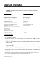
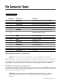
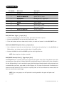
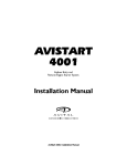
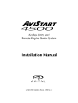
2
Maxx
Installation Guide
© 2002 Directed Electronics, Inc. Vista, CA N840002 5-02
Table of Contents
Important Information . . . . . . . . . . . . . . . . . . . . . . . . . . . . . . . . . . . . . . . . . . . . . . . . . . . . . . . 3
System Components . . . . . . . . . . . . . . . . . . . . . . . . . . . . . . . . . . . . . . . . . . . . . . . . . . . . . . . . 3
Required Installation Tools . . . . . . . . . . . . . . . . . . . . . . . . . . . . . . . . . . . . . . . . . . . . . . . . . . . 3
Recommended Procedures . . . . . . . . . . . . . . . . . . . . . . . . . . . . . . . . . . . . . . . . . . . . . . . . . . . . 3
Installation Procedures . . . . . . . . . . . . . . . . . . . . . . . . . . . . . . . . . . . . . . . . . . . . . . . . . . . . . . . 4
Control Unit . . . . . . . . . . . . . . . . . . . . . . . . . . . . . . . . . . . . . . . . . . . . . . . . . . . . . . . . . . . . . 4
Antenna . . . . . . . . . . . . . . . . . . . . . . . . . . . . . . . . . . . . . . . . . . . . . . . . . . . . . . . . . . . . . . . 4
Valet Switch . . . . . . . . . . . . . . . . . . . . . . . . . . . . . . . . . . . . . . . . . . . . . . . . . . . . . . . . . . . . . 4
LED Indicator . . . . . . . . . . . . . . . . . . . . . . . . . . . . . . . . . . . . . . . . . . . . . . . . . . . . . . . . . . . . 4
Siren . . . . . . . . . . . . . . . . . . . . . . . . . . . . . . . . . . . . . . . . . . . . . . . . . . . . . . . . . . . . . . . . . 4
Ultrasonic Sensitivity Adjustment . . . . . . . . . . . . . . . . . . . . . . . . . . . . . . . . . . . . . . . . . . . . . . . 5
Ultrasonic Sensors . . . . . . . . . . . . . . . . . . . . . . . . . . . . . . . . . . . . . . . . . . . . . . . . . . . . . . . . . 5
Pin Connector Charts . . . . . . . . . . . . . . . . . . . . . . . . . . . . . . . . . . . . . . . . . . . . . . . . . . . . . . . . 6
18-Pin Connector (P1) . . . . . . . . . . . . . . . . . . . . . . . . . . . . . . . . . . . . . . . . . . . . . . . . . . . . . . 6
10-Pin Connector (P2) . . . . . . . . . . . . . . . . . . . . . . . . . . . . . . . . . . . . . . . . . . . . . . . . . . . . . . 8
Final Wiring Connections. . . . . . . . . . . . . . . . . . . . . . . . . . . . . . . . . . . . . . . . . . . . . . . . . . . . . 9
System Status/Diagnostic Charts . . . . . . . . . . . . . . . . . . . . . . . . . . . . . . . . . . . . . . . . . . . . . . . 10
LED System Status Indicator . . . . . . . . . . . . . . . . . . . . . . . . . . . . . . . . . . . . . . . . . . . . . . . . . 10
Specific Zone Intrusion Identification . . . . . . . . . . . . . . . . . . . . . . . . . . . . . . . . . . . . . . . . . . . 10
Chirp/Indicator Light Flash Interpretation. . . . . . . . . . . . . . . . . . . . . . . . . . . . . . . . . . . . . . . . . 11
Door Lock Diagrams . . . . . . . . . . . . . . . . . . . . . . . . . . . . . . . . . . . . . . . . . . . . . . . . . . . . . . . . . 12
Personal Identification Number (PIN) . . . . . . . . . . . . . . . . . . . . . . . . . . . . . . . . . . . . . . . . . . . . 17
Entering Your PIN . . . . . . . . . . . . . . . . . . . . . . . . . . . . . . . . . . . . . . . . . . . . . . . . . . . . . . . . 17
Programmable Features . . . . . . . . . . . . . . . . . . . . . . . . . . . . . . . . . . . . . . . . . . . . . . . . . . . . . . 18
Programming Table for System Features . . . . . . . . . . . . . . . . . . . . . . . . . . . . . . . . . . . . . . . . . . 19
Programming Table for Remote Controls . . . . . . . . . . . . . . . . . . . . . . . . . . . . . . . . . . . . . . . . . . 20
Final Testing Checklist . . . . . . . . . . . . . . . . . . . . . . . . . . . . . . . . . . . . . . . . . . . . . . . . . . . . . . 21
Certificate of Installation . . . . . . . . . . . . . . . . . . . . . . . . . . . . . . . . . . . . . . . . . . . . . . . . . . . 21
Wiring Diagrams . . . . . . . . . . . . . . . . . . . . . . . . . . . . . . . . . . . . . . . . . . . . . . . . . . . . . . . . . . . 22
2
© 2002 Directed Electronics, Inc.
Important Information
IMPORTANT! The Avital Maxx2 system is designed to be installed in any petrol powered vehicle with
a 12 volt battery.
system components
required installation tools
One Avital Maxx2 Control Unit
Voltmeter
One Prewired 18-Pin Connector Harness
Wire Strippers/cutters
One Prewired 10-Pin Connector Harness
Electric Drill & Bits
One Prewired Valet Switch
Convoluted Tubing *
One Prewired Status LED
Soldering Iron
One 4-Button 10-Channel Remote Control
Wire Crimpers
One 2-Button 3-Channel Remote Control
Shrink Tube or Electrical Tape
Two Ultrasonic Transducers
Phillips Screwdriver
One Battery Back-up Siren with Mounting Bracket
One Hardware Pack
One Owner’s Guide
One Certificate of Installation
Two Avital Window Decals
* Optional
recommended procedures
1. Test all circuits with a voltmeter.
2. Make all wiring connections using solder and heatshrink using the procedure below. Do NOT twist wires or
use scotch-lock connectors.
•
Strip half an inch of insulation from the wires you are going to solder and slide a piece of shrink tubing
over one of them.
•
Join the wires together, then heat the wires with a soldering iron whilst touching solder to the wires
until the solder melts.
•
Pull the wires to test the solder joint, then position the loose shrink tube over the solder joint and gently
heat with a hot air gun so that it tightly seals and insulates.
3. Keep extensions as short as possible. Use the same gauge wires for short extensions and larger gauge wires
for longer extensions.
4. Before installing, discuss the placement of the LED indicator and Valet switch with the vehicle’s owner.
5. Turn off interior light(s) or remove interior light fuse to prevent battery drain.
© 2002 Directed Electronics, Inc.
3
Installation Procedures
Control Unit
CAUTION: The Avital Maxx2 control unit must be installed inside the vehicle. Under no circumstances should the unit be installed under the bonnet or other similarly hostile environment.
1. Select a location under the dash that will allow you to use the screws to securely fasten the control unit.
2. Mount the control unit as high as possible to ensure maximum range.
3. Do not mount the control unit near moving parts.
4. Avoid areas that are in the direct path of air blowing from the heater vents.
5. Route wires from this point, leaving slack for ease of service.
Antenna
1. Do not shorten or lengthen the antenna.
2. Route the antenna away from the control unit.
3. Keep the antenna as far away from metal and wire harnesses as possible to optimise range.
Valet Switch
1. Discuss placement with the vehicle’s owner.
2. Choose a location for the Valet switch that is convenient for the owner to access.
3. Drill a 7mm hole and mount the switch.
LED Indicator
1. Discuss placement with the vehicle’s owner.
2. Choose a location that is visible from both sides of the vehicle.
3. Drill a 7mm hole.
4. Insert the LED into the black mounting collar.
5. Push the LED and collar into the 7mm hole.
Siren
1. Choose a location in the engine compartment away from high temperature engine components, moving parts
and direct exposure to water.
2. Make sure the siren and siren wires cannot be seen or reached from below the vehicle.
3. Mount the siren with the two self-tapping screws to a solid metal surface.
4. Route the siren cable through the firewall into the passenger compartment.
5. Make the wire connection as per the diagram on page 23.
4
© 2002 Directed Electronics, Inc.
Ultrasonic Sensors
1. Choose a location at the top of the A-pillar on both driver and passenger sides.
2. Mount the sensors using the screws provided or by inserting the mounting tabs between the dashboard and
windscreen pillar.
3. Angle the sensors towards the top centre of the rear window. If mounted at the top of the A-pillars make
sure the ultrasonic position does not affect use of the sunvisor.
4. Route the sensor cables to the control module and plug-in.
Ultrasonic Sensitivity Adjustment
1. Follow the instructions for entering program mode on page 19. Enter program branch number 19 on page 20
listed as "Ultrasonic Sensor Test and Adjustment Mode."
2. Once in this mode the system LED will flash ON and the siren will chirp if movement is detected inside the
vehicle.
3. The sensitivity adjuster is found on the side of the main Alarm/Immobiliser Control Unit. Insert a small screwdriver into the adjustment hole and turn the screw clockwise to increase sensitivity or anti-clockwise to
decrease sensitivity.
4. Move your arm through an open window on the vehicle as if attempting to remove an item from the seat.
The LED should illuminate and the siren should chirp to detect the movement. If it does not, then increase
the sensitivity in small increments until the optimum position is reached and the sensors do pick up the
movement. Do not over adjust the sensors as the system will false alarm. The sensitivity level should be left
at the minimum setting where the sensors pick up movement in the rear seating position.
5. When satisfied with the final sensitivity setting, you may exit Installer Ultrasonic setup mode by either
turning off the ignition or by pressing any remote control button. Program mode exit will be confirmed by
two siren chirps (one short and one long chirp).
© 2002 Directed Electronics, Inc.
5
Pin Connector Charts
18-Pin Connector (P1)
Pin Number
Wire Colour
Description
1
WHITE/BLUE
Channel 4 Accessory (-) Pulsed or Timed Output
2
PINK/BLACK
Second Stage Unlock (-) Output
3
VIOLET/WHITE
Arm/Disarm (-) Output (300mA maximum)
4
GREY/BLACK
Channel 5 Accessory (-) Pulsed or Latched Output
5
BROWN
Coded Link for Siren
6
RED/WHITE
Channel 2 Accessory (-) Pulsed for Boot Release
7
8
9
Pre-Wired to Ultrasonic Sensors
10
WHITE
Indicator Light Output
11
BLACK with WHITE TAG
Indicator Light Polarity (+) or (-) Input Select
12
WHITE
Indicator Light Output
13
BLUE/BLACK
Unlock Common
14
VIOLET
Unlock Normally Open
15
BROWN/BLACK
Unlock Normally Closed
16
WHITE/BLACK
Lock Normally Closed
17
VIOLET/BLACK
Lock Normally Open
18
GREEN/BLACK
Lock Common
WHITE/BLUE Channel 4 Accessory (-) Output (P1/1)
CAUTION: Do not use this output to roll-up windows on vehicles not equipped with "Total-close."
The WHITE/BLUE wire can be programmed to provide a (-) output from one second to two minutes. The wire can
also be programmed to automatically activate when the alarm system is armed. This output can be used to activate headlights, roll-up/down windows and close sunroofs on vehicles equipped with factory "Total-close."
PINK/BLACK Second Stage Unlock (-) Output (P1/2)
The alarm has onboard relays to lock and unlock the doors. It also incorporates a PINK/BLACK (-) output wire
that will allow the customer to operate a Two-Stage Unlock feature. The second stage unlock wire provides a 400
mA, 0.75 second (-) output when activated.
CAUTION: Ask the customer at the time of installation whether they require this feature. Verify the
type of central locking system the vehicle has. Carefully follow the door lock/unlock diagrams on
pages 12-16.
6
© 2002 Directed Electronics, Inc.
1. Press the
button once and the driver’s door only will unlock.
2. Press the
button again within three seconds and the passenger doors will unlock.
VIOLET/WHITE Arm/Disarm (-) Output (300 mA maximum) (P1/3)
The VIOLET/WHITE wire can be connected to a pager or used to drive a relay when adding extra sirens. This wire
pulses to ground (-) when the siren chirps and will stay at ground for as long as the siren is sounding.
GREY/BLACK Channel 5 Accessory (-) Output (P1/4)
The GREY/BLACK wire can be programmed to provide a PULSED 0.75 second ground (-) or LATCHED output. If the
remote control button is continuously pressed when programmed for a PULSED output, the signal will stay at
ground for as long as the button is held. If the remote control button is pressed when programmed for a LATCHED
output, the signal will stay at ground until such time as the button is pressed a second time.
BROWN Coded Link for Siren (P1/5)
The BROWN wire is the siren's data connection. This wire controls whether the siren should chirp or sound, etc.
Connect the BROWN wire to the BROWN siren wire.
NOTE: Do not connect anything other than the system siren to this wire or damage may occur.
RED/WHITE (P1/6)
The RED/WHITE wire provides a 0.75 second ground (-) output when the alarm is disarmed only. This is ideal for
boot release. If the remote control button is continuously pressed, the signal will stay at ground for as long as
the button is held.
NOTE: Most boot releases are switched positive and require an additional relay.
2 BLACK Screened Wires Pre-Wired to Ultrasonic Sensors (P1/7, 8, & 9)
These wires are to be plugged into the two ultrasonic sensors.
2 WHITE & BLACK with WHITE TAG Indicator Lights (P1/10, 11, & 12)
1. If the indicator lights are positive trigger, connect the BLACK wire with WHITE tag to the constant positive
(+) battery terminal through the 20 amp fuse provided.
NOTE: Do not connect the BLACK wire with WHITE tag to the control unit BLACK wire with RED tag.
2. If the indicator lights are negative (-) trigger, connect the BLACK wire with WHITE tag to the control unit
BLACK wire with GREEN tag.
3. Connect the WHITE wires to the left and right indicator light wires on the vehicle.
On-Board Door Lock Relays (P1/13-P1/18)
For installation instructions, see Door Lock Diagrams beginning on page 12.
© 2002 Directed Electronics, Inc.
7
10-Pin Connector (P2)
Pin Number
Wire Colour
Description
1
NOT USED
Not Used
2
BLUE/WHITE
Boot Trigger (-) Input
3
BLACK with ORANGE TAG
Ignition Sense (+) Input
4
BLACK/WHITE
Normally Closed (-) Trigger Input
5
GREY
Prewired To Valet Switch
6
ORANGE
Armed (-) Output
7
BLUE
Bonnet Trigger (-) Input
8
GREEN
(-) Door Trigger Input, Interior Light
Illumination (-) Output
9
BLACK with GREEN TAG
12 volt (-) Input x2
10
BLACK with RED TAG
12 volt (+) Input
BLUE/WHITE Boot Trigger (-) Input (P2/2)
1. Locate the vehicle boot pin switch that shows ground when the boot is opened.
2. Connect the BLUE/WHITE wire to the vehicle boot switch wire.
3. If the vehicle does not have a boot switch, install a pin switch and connect it to the BLUE/WHITE wire.
BLACK with ORANGE TAG Ignition Sense (+) Input (P2/3)
1. Use a voltmeter to locate the one wire that shows 12 volts when the ignition key is in the ON, CRANK and
RUN positions, and 0 volts when the ignition key is in the OFF position.
2. Connect the BLACK wire with the ORANGE tag to the vehicle ignition wire.
NOTE: Remove tag from wire after connection.
BLACK/WHITE Normally Closed (-) Trigger Input (P2/4)
The BLACK/WHITE wire is a normally closed input as opposed to the systems sensor, door, & boot/bonnet inputs which
are normally open. Some vehicles are factory fitted with normally closed bonnet pin switches which can be connected to
this wire. Or alternatively, it can be connected to ground after being looped through external ancillary equipment such
as mountain bikes, spot lamps, spare wheels, in-dash CD players, etc. The input can also be used for connection to a
heated rear window switched wire. This last option is especially useful as if the rear windscreen was removed whilst the
alarm was armed the alarm would trigger.
NOTE: If you are not going to use this Input then it must be grounded or the system will report a malfunction.
8
© 2002 Directed Electronics, Inc.
GREY Prewired to Valet Switch (P2/5)
The GREY wire is switched to ground whenever the valet switch is pressed.
ORANGE Armed (-) Output (P2/6)
The ORANGE wire will provide a ground (-) output for as long as the alarm is Armed. It does not provide a ground
when the system is Disarmed.
BLUE Bonnet Trigger Input (P2/7)
1. Locate the vehicle bonnet pin switch that shows ground when the bonnet is opened.
2. Connect the BLUE wire to the BLUE siren wire. Connect the bonnet switch to the BLUE wire exiting the siren
harness at the siren.
3. If the vehicle does not have a bonnet switch, install a pin switch and connect it to the BLUE wire exiting
the siren harness at the siren.
GREEN Door Trigger/Interior Light Illumination (P2/8)
The system has a negative door trigger input. If the vehicle door trigger is negative (-) switching, connect the
alarm GREEN wire to the vehicle door trigger wire. For vehicles that have a positive door trigger, a relay will need
to be added to provide the GREEN wire with a negative when the door is open.
NOTE: When the alarm is remotely disarmed, the GREEN wire will provide a negative output to turn
the interior lights on.
BLACK with GREEN TAG, BLACK with RED TAG Power and Ground Connections (P2/9 & 10)
CAUTION: Do not plug in the system fuses until the final step below.
1. Connect the BLACK wire with RED tag to one of the supplied fuse assemblies.
2. Connect the BLACK wires with GREEN tags to separate chassis ground locations.
3
Connect the empty fuse assembly(s) to the positive battery post.
NOTE: This wire must be a minimum of 14 gauge.
Final Wiring Connections
1. Inspect all alarm wiring. Make sure all wires are connected.
2. Install the 5 amp fuse in the BLACK wire with RED tag fuse assembly.
3. Install the 20 amp fuse in the BLACK wire with WHITE tag fuse assembly (if the vehicle indicator lights are
positive).
NOTE: Remove tags from wires after connection.
© 2002 Directed Electronics, Inc.
9
System Status/Diagnostic Charts
LED System Status Indicator
LED
Status
Off
System is disarmed.
On
In Valet mode.
Double Flash
System is armed.
Triple Flash
More than three consecutive incorrect Valet
codes have been entered (system ignores
Valet switch for two minutes).
Flashing in Cycles
See "Specific Zone Intrusion Identification"
chart below.
Rapid Flash
Passive arming countdown.
Specific Zone Intrusion Identification
If the alarm has been triggered, the siren will chirp three times upon remote disarm. Turn the ignition ON and
count the LED flashes. Each flash cycle is repeated two more times giving three cycles in total.
10
LED
Zone
Input Description
Three Flashes
Optional Sensor 2
Dual Zone 4-pin
Four Flashes
Door Trigger Input (-)
P2 Pin 8 GREEN
Five Flashes
Boot/Bonnet Trigger
P2 Pin 2 BLUE/WHITE or Pin 7 BLUE
Six Flashes
Normally Closed Trigger Input (-)
P2 Pin 4 BLACK/WHITE
Seven Flashes
Ultrasonic Sensor
P1 Pin7/8/9 Ultrasonic sensors
Eight Flashes
Ignition Trigger
P2 Pin 3 BLACK with ORANGE Tab
© 2002 Directed Electronics, Inc.
Chirp/Indicator Light Flash Interpretation
When you press the remote buttons, the system will respond with chirps and indicator light flashes. This is to
indicate the system status and to alert you to any active trigger or sensor input.
Number of chirps and flashes
Explanation
1 chirp, 1 flash
Disarming of the alarm.
2 chirps, 2 flashes
Arming of the alarm.
3 chirps, 3 flashes
Disarmed and there was an intrusion attempt.
2 chirps and flashes,
then 3 more chirps and flashes
Armed and a door is ajar.
2 chirps and flashes,
then 4 more chirps and flashes
Armed and there is a sensor input active
(automatically bypassed).
2 chirps and flashes, then 5 more chirps and flashes
Armed and there is a boot, bonnet, or normally closed
trigger input active (automatically bypassed).
© 2002 Directed Electronics, Inc.
11
12
© 2002 Directed Electronics, Inc.
© 2002 Directed Electronics, Inc.
13
14
© 2002 Directed Electronics, Inc.
© 2002 Directed Electronics, Inc.
15
16
© 2002 Directed Electronics, Inc.
Personal Identification Number (PIN)
Each system has an individual four-digit PIN. In order to access Valet mode or any of the programmable features,
you must first enter the PIN, one number at a time.
NOTE: To enter a zero, simply turn the ignition on and then off without pressing the Valet switch.
Entering Your PIN
1. Turn the ignition key to the ON position.
2. Enter the first number in your PIN. Press and release the Valet switch the same number of times as the first
digit in your PIN. Example: If your PIN is 2345, press the Valet switch two times.
3. Turn the ignition key OFF.
4. Turn the ignition key to the ON position.
5. Enter the second number in your PIN. Press and release the Valet switch the same number of times as the
second digit in your PIN. Example: If your PIN is 2345, press the Valet switch three times.
6. Turn the ignition key OFF.
7. Turn the ignition key to the ON position.
8. Enter the third number in your PIN. Press and release the Valet switch the same number of times as the third
digit in your PIN. Example: If your PIN is 2345, press the Valet switch four times.
9. Turn the ignition key OFF.
10. Turn the ignition key to the ON position.
11. Enter the last number in your PIN. Press and release the Valet switch the same number of times as the last
digit in your PIN. Example: If your PIN is 2345, press the Valet switch five times.
12. Turn the ignition key OFF. If you have entered the correct code you will hear two chirps (one short and one
long). Should you hear five rapid chirps, the correct code has not been entered. Begin entering your PIN from
the beginning.
13. To enter Valet mode, now turn the ignition on and press and hold the Valet switch for three seconds until
the LED illuminates constantly. The system will automatically exit Valet mode the next time the ignition is
switched ON.
© 2002 Directed Electronics, Inc.
17
Programmable Features
All system features and remote control features are accomplished by entering your Personal Identification Number
(PIN) by following steps 1-12 on page 18, then pressing the Valet switch a preset number of times to access the
feature you wish to program.
The system also allows you to add new remote controls in one step and delete lost or stolen remote controls.
1. Programming cannot be accessed while the system is in Valet mode indicated by the LED permanently lit.
Remove the system from Valet mode by turning on the ignition. The LED should turn off automatically.
2. Select the feature you wish to program from the Programming Table for System Features or the Programming
Table for Remote Controls sections of this guide. Note the number of chirps associated with that feature.
3. Follow steps 1-12 in the Entering Your Pin section of this guide.
4. Begin to press and release the Valet switch. The siren will chirp once each time you press and release the
Valet switch.
5. Continue pressing and releasing the Valet switch, counting the siren chirps.
NOTE: Stop when you reach the number of chirps associated with your chosen feature. The system
LED will give confirmation of the feature status. If the LED is ON, the feature is ON. If the LED is
OFF, the feature is OFF.
6. Follow the "Secondary Action" listed in the programming table. You will hear one or two chips and the system
LED will give you confirmation that you have changed the feature.
7. After you have programmed the feature you have chosen, you can exit programming by turning the ignition
key OFF. You will hear two chirps to confirm exit of program mode. If you wish to program additional features, leave the ignition ON and press the Valet switch again. The system will advance to the next feature.
Continue pressing and releasing the Valet switch until you have reached your next chosen feature.
18
© 2002 Directed Electronics, Inc.
Programming Table for System Features
Feature
Factory Setting
No. of Chirps
Passive Arming
ON
2
Press
button. The siren will chirp
once for OFF, twice for ON.
Passive Arm with Door Lock
OFF
3
Press
button. The siren will chirp
once for OFF, twice for ON.
Auto Rearm and Door Lock
ON
4
Press
button. The siren will chirp
once for OFF, twice for ON.
Ignition Controlled
Lock/Unlock
ON
5
Press
button. The siren will chirp
once for OFF, twice for ON.
2.5 Seconds
6
Press
button. The siren will chirp
once for 0 seconds, twice for 2.5 seconds.
1 Second
7
Press
button. The siren will chirp
once for 3 seconds, twice for 1 second.
ON
8
Press
button.The siren will chirp
once for OFF, twice for ON.
1 Second
9
Press
Press
OFF
10
Press
button. The siren will chirp
once for OFF and twice for ON.
Channel 5 Accessory
Output
Pulsed
11
Press
button. The siren will chirp
once for Latched, twice for Pulsed.
Indicator Light Flash
Confirmation
ON
12
Press
button. The siren will chirp
once for OFF, twice for ON.
Door Ajar Indication
ON
13
Press
button.The siren will chirp
once for OFF, twice for ON.
Single
14
Press
button. The siren will chirp
once for Single, twice for Dual.
Double Lock Pulse
Single Pulse
15
Press
button. The siren will chirp
once for Single Pulse, twice for Double
Pulse.
Double Unlock Pulse
Single Pulse
16
Press
button. The siren will chirp
once for Single Pulse, twice for Double
Pulse.
Pin Code Digits 1 and 2
Factory Selected
17
Press
button, 1 to 9 times to set
first digit of PIN code. Press
button, 1 to
9 times to set the second digit of PIN code.
If you require a 00 (zero, zero) in the PIN
code, press
+
buttons at the same
time.
Pin Code Digits 3 and 4
Factory Selected
18
Press
button, 1 to 9 times to set
third digit of PIN code. Press
button, 1
to 9 times to set fourth digit of PIN code.
If you require a 00 (zero, zero) in the PIN
code, press
+
buttons at the same
time.
—
19
See Explanation on Page 5.
Programmable 0 or 2.5
Second Delay for Ignition
Controlled Door Lock/Unlock
Door Lock/Unlock
Duration (1-3 second)
Arm/Disarm Siren Chirps
Channel 4 Accessory
Output Duration
Channel 4 Auto
Activation Upon
Remote Arming
Dual Sensor trigger Mode
Ultrasonic Sensor Test
and Adjustment Mode
© 2002 Directed Electronics, Inc.
Secondary Action
button to start timer.
button to stop the timer.
19
Programming Table for Remote Controls
Feature
Factory Setting
Arm/Disarm/Panic
Two Stage Unlock
Button Channel 1
No. of Chirps
Secondary Action
20
Press any remote button(s). The siren will
chirp once for confirmation.
Accessory(-) Output for
Boot Release (disarmed only)
Button Channel 2
21
Press any remote button(s). The siren will
chirp twice for confirmation.
Silent Arm/Disarm
Button Channel 3
22
Press any remote button(s). The siren will
chirp 3 times for confirmation.
Accessory(-) Output Timed
Button Channel 4
23
Press any remote button(s). The siren will
chirp 4 times for confirmation.
Button Channel 5
24
Press any remote button(s). The siren will
chirp 5 times for confirmation.
Button Channel 6
25
Press any remote button(s). The siren will
chirp 6 times for confirmation.
Accessory(-) Output
Pulsed/Latched
Remote Sensor Bypass
+
+
All Channel Learn
—
26
Press
button. The siren will chirp
once to confirm factory preset order.
Instant Code Deletion
—
27
Wait 3 seconds. The siren will chirp twice.
All remotes are erased from memory.
NOTE: When assigning channels to different buttons from factory you must "All Channel Learn" a
transmitter and then change the individual assignments with feature number 20 to 25 as required.
20
© 2002 Directed Electronics, Inc.
Final Testing Checklist
■ In the "Recommended Procedures" section on page 3, you removed the interior light fuse. You must now
replace it, shut the vehicles doors, boot and bonnet and arm the alarm by pressing the
button (indi-
cated by LED double flash sequence). If you connected the alarm to the vehicles central locking the doors
should lock, the siren should chirp twice and the indicators should flash twice.
■ Unlock and open a door. The alarm should sound and indicators should flash. Press the
button to reset
the siren. Follow this procedure for every trigger point (all doors, boot/tailgate and bonnet). When all trigger
points have been tested disarm the alarm fully by pressing the
or
button twice.
■ Open a window. Arm the alarm system, wait at least 20 seconds and then reach inside the car to trigger the
Ultrasonic sensors. The alarm should sound. Press the
button to reset the siren and turn the ignition
on. Again, the alarm should sound. Fully disarm the system.
■ Test the Valet PIN code is working by entering Valet mode. Turn the ignition on. The LED should turn off and
the system will exit Valet mode automatically.
■ Test the remote control range. Stand approximately 50 feet from the car and press the
or
button.
The alarm should arm/disarm.
Certificate of Installation
After Installation and testing you must fill out the certificate of installation. Once you have filled out all information on the certificate the customer must sign and date it. Distribute the copies as follows:
White (top) copy - Customer
Blue copy - Customer’s insurance broker
Pink copy - Directed Electronics UK Office
Green Copy - Installing Dealer
© 2002 Directed Electronics, Inc.
21
Wiring Diagrams
NOTE: The current draw for the entire security system when in the armed state is 20mA. Power
supply voltage range is 9 volts to 15 volts.
22
© 2002 Directed Electronics, Inc.
NOTE: Remove all tags from wires after connection.
© 2002 Directed Electronics, Inc.
23