1
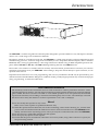
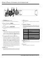
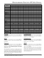
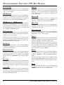
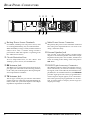
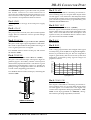
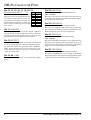
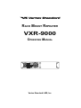
RACK MOUNT REPEATER
VXR-9000
OPERATING MANUAL
Vertex Standard LMR, Inc.
VXR-9000 FM REPEATER OPERATING MANUAL
VXR-9000 FM REPEATER OPERATING MANUAL
INTRODUCTION
The VXR-9000 is commercial-grade 50-watt FM repeater designed to provide reliable two-way full-duplex communications over a wide range of environmental conditions.
Designed to mount in a standard 19-inch rack, the VXR-9000 is crafted using the latest computer-aided design and
manufacturing processes, to ensure a high level of reliability to users. Important channel frequency data is stored in
EEPROM, and is easily programmable by a Servicing Technician or Dealer using an IBM compatible personal computer and the FIF-10A (or FIF-12) + CT-104A USB Programming Interface and CE60 Software.
Please take a few minutes to read this manual carefully. The information presented here will allow you to derive
maximum performance from your VXR-9000. After reading it, keep this manual handy for quick reference, in case
questions arise later on.
Important Note: Internal service work, programming, and accessory installations should only be performed by your
authorized Vertex Standard Dealer. Dangerous conditions and/or possibly illegal operation may result from improper
setup, programming, or internal modifications.
SAFETY/WARNING INFORMATION
The antenna(s) used for this transmitter must be fixed-mounted on outdoor permanent structures with a
separation distance of at least 1.4 m from all persons during normal operation and must not exceed an antenna
gain of 0 dBd. This device must be restricted to work related operations in an Occupational/Controlled RF
exposure Environment, not exceeding a maximum transmitting duty factor of 50%. The antenna(s) used with
this device must satisfy the antenna co-location requirements of 47 C.F.R. 1.1307(b)(3).
NOTICE!
Do not modify this repeater for any reason.
Refer service of this repeater to qualified technicians only.
When the repeater become abnormal, such as the overheating, smoke smell of burning, etc., turn the main
power switch off and disconnect the Main Power Source connector from the rear of the VXR-9000 immediately. Also disconnect any backup power source you may have connected to the rear of the VXR-9000.
Do not place any combustible material near the repeater.
Do not spray any liquid over the repeater.
Ensure that the power and antenna connections are securely made, using cables with excess capacity for
the power being utilized.
VXR-9000 FM REPEATER OPERATING MANUAL
1
FRONT PANEL CONTROLS & CONNECTORS
POWER (O/I) Switch
This is the main power switch for the repeater.
Power Indicator (MAIN)
This LED glows green when the main power source
is used.
Power Indicator (BACKUP)
This LED glows red when the backup power source
is used.
MIC Jack
Connect the microphone plug to this jack. This jack
is also used for writing and reading channel frequency or other configurations via the USB Port of
the PC on which the clone editor (CE60) is running.
Programmable Function (PF) Key
Six pushbuttons on the front panel are programmable function (PF) keys, each with an orange indicator inside. Each key can be programmed with two
functions, one for a “long” press and one for a “momentary” press. The PF key functions may be customized, via programming by your VERTEX STANDARD dealer, to meet your communications network requirements. Note that some functions may
require the purchase of optional internal accessories. The possible PF key features and functions are
explained on the pages to follow.
TX Indicator
This LED glows red when the repeater is transmitting.
Numeric Display
This display consists of two 7-segment LEDs, indicating the channel number during normal operation.
If an abnormal condition arises, an error code will be
displayed:
DISPLAY
DESCRIPTION
01 - 32
PC
UL
HI
SC
LC
E1
E2
E5
E7
E3, E4, E6, E9
Channel Number
Clone Active
PLL Unlock
High temperature in PA Unit
Scan Active
Front Panel Keys are Locked
PTT key is Disabled
Cooling Fan is Disabled
Low Voltage in Backup Battery
PA Unit Abnormality
Contact your Dealer
BUSY Indicator
This LED glows green when the receiving channel
is busy.
Speaker
The internal speaker is located here.
VOL Knob
This control knob adjusts the output level of the front
speaker and external speaker jack on the back panel.
2
VXR-9000 FM REPEATER OPERATING MANUAL
PROGRAMMABLE FUNCTION (PF) KEY DETAILS
FUNCTION
PF-1 KEY
PRESS PRESS & HOLD
PF-2 KEY
PRESS PRESS & HOLD
PF-3 KEY
PRESS PRESS & HOLD
PF-4 KEY
PRESS PRESS & HOLD
PF-5 KEY
PRESS PRESS & HOLD
PF-6 KEY
PRESS PRESS & HOLD
CH DOWN
CH UP
COMPANDER
CTCSS/DCS ENC
CTCSS/DCS DEC
CW ID
TWO TONE DEC
CW ID SIGNAL
CW MESSAGE 1
CW MESSAGE 2
CW MESSAGE 3
CW MESSAGE 4
CW MESSAGE 5
CW MESSAGE 6
CW MESSAGE 7
CW MESSAGE 8
DC POWER SAVE
ENCRYPTION
ENCRYPTION CODE
KEY LOCK
LOCAL PTT
MONITOR
MONITOR M
MULTI TONE
PANEL INDICATOR
REMOTE
REPEAT
RESET
SCAN
SQUELCH
TEST TONE
TEST TONE M
TOT
TRANSMIT
TX POWER MID
TX POWER LOW
CH DOWN
CTCSS/DCS ENC
Press (or Press and hold in for one second) the PF key
assigned to “CH Down” to step to the next-lower operating channel.
Press (or Press and hold in for one second) the PF key
assigned to “CTCSS/DCS Enc” to turn the CTCSS/DCS
Encoder “On” or “Off” (toggle).
CH UP
CTCSS/DCS DEC
Press (or Press and hold in for one second) the PF key
assigned to “CH Up” to step to the next-higher operating channel.
Press (or Press and hold in for one second) the PF key
assigned to “CTCSS/DCS Dec” to turn the CTCSS/DCS
Decoder “On” or “Off” (toggle).
COMPANDER
CW ID
Press (or Press and hold in for one second) the PF key
assigned to “Compander” to turn the Compander circuit “On” or “Off” (toggle). This function is only activated on the “Narrow Channel Spread” of the “Base
Transceiver” mode.
Press (or Press and hold in for one second) the PF key
assigned to “CW ID” to turn the CW Identifier feature
“On” or “Off” (toggle).
The Compander IC contains two variable gain circuits
configured for compressing and expanding the dynamic
range of the repeater’s transmitted and received audio
signal. When you enable this function, the signal-tonoise ratio can be improved by reducing the transmitted audio dynamic range.
VXR-9000 FM REPEATER OPERATING MANUAL
When the CW ID feature is set to “On,” your station’s
callsign will be superimposed on the outbound signal,
in Morse Code, at the beginning of every transmission.
Programming of the callsign is performed by your VERTEX STANDARD dealer.
3
PROGRAMMABLE FUNCTION (PF) KEY DETAILS
TWO TONE DEC
MONITOR
Press (or Press and hold in for one second) the PF key
assigned to “Two Tone Dec” to turn the 2-Tone Decoder
“On” or “Off” (toggle).
Press (or Press and hold in for one second) the PF key
assigned to “Monitor” to cancel CTCSS and DCS squelch
decoding, so as to enable reception of signals present
on the channel that do not contain a matching CTCSS
tone or DCS code.
CW ID SINGLE
Press (or Press and hold in for one second) the PF key
assigned to “CW ID Single” to send the station callsign,
via Morse Code, once. Programming of the callsign is
performed by your VERTEX STANDARD dealer.
MONITOR M
This function provides to “Monitor” to cancel CTCSS
and DCS squelch decoding, so long as the PF key assigned to “Monitor M” is pressed and held in.
CW MESSAGE 1 - CW MESSAGE 8
Press (or press and hold in for one second) the PF key
assigned to “CW Message 1 - 8” to send a pre-programmed Morse Code message on the transmitted signal. Programming of the message(s) is performed by
your VERTEX STANDARD dealer.
MULTI TONE
Press (or Press and hold in for one second) the PF key
assigned to “Multi Tone” to switch the Tone Table between “Main” and “Sub.”
PANEL INDICATOR
DC POWER SAVE
Press (or Press and hold in for one second) the PF key
assigned to “DC Power Save” to turn the DC Power Save
feature “On” or “Off” (toggle).
When DC Power Save feature is set to “ON,” activate
the various power save feature (determined from your
VERTEX STANDARD dealer) while the repeater operates from the Backup Power Source.
Press (or Press and hold in for one second) the PF key
assigned to “Panel Indicator” to turn the Front Panel’s
Illumination “On” or “Off” (toggle).
REMOTE
Press (or Press and hold in for one second) the PF key
assigned to “Remote” to toggle the operating mode between the “Remote” mode and “Local” mode.
Press (or Press and hold in for one second) the PF key
assigned to “Encryption” to turn off the Optional Encryption Unit temporarily.
When the “Remote” mode is selected, the repeater operates according to the control instructions received from
the external device (connected to the ACC jack on the
rear panel). While in the “Local” mode, the repeater operates from the front panel’s PF keys.
ENCRYPTION CODE
REPEAT
Press (or Press and hold in for one second) the PF key
assigned to “Encryption Code” to select the Encryption
Code (determined from your VERTEX STANDARD
dealer; require the FVP-35 Rolling Code Encryption
Unit).
Press (or Press and hold in for one second) the PF key
assigned to “Repeat” to toggle the operating mode between the “Repeater” mode and “Base Transceiver”
mode.
ENCRYPTION
KEY LOCK
Press (or Press and hold in for one second) the PF key
assigned to “Key Lock” to lock the repeater’s front panel
keys (except “Key Lock” key); this feature can be enabled to prevent repeater settings from being disturbed.
LOCAL PTT
Press (or Press and hold in for one second) the PF key
assigned to “Local PTT” to enable (“On”) or disable
(“Off”) operation using a PTT switch connected to the
front panel’s Microphone Jack.
4
For normal operation, set this key to the “Repeat” mode.
When the “Base Transceiver” mode is selected, you can
speak into the microphone to use this repeater as a transceiver.
RESET
Press (or Press and hold in for one second) the PF key
assigned to “Reset” to reset (same function as the
POWER switch “off” and “on”) the repeater.
VXR-9000 FM REPEATER OPERATING MANUAL
PROGRAMMABLE FUNCTION (PF) KEY DETAILS
SCAN
TOT
Press (or Press and hold in for one second) the PF key
assigned to “Scan” to start scanning. To stop scanning,
press (or Press and hold in for one second) this key again.
Press (or press and hold in one second) the PF key assigned to “TOT” to turn the Time-Out Timer feature
“On” or “Off” (toggle).
The scanning feature is used to monitor multiple channels programmed into the repeater.
When the TOT feature is set to “On,” the repeater will
return to the “Receive” mode automatically after a preset time of continuous transmission (determined via
programming by your VERTEX STANDARD dealer).
This function is only activated on the “Base Transceiver”
mode.
SQUELCH
Press (or Press and hold in for one second) the PF key
assigned to “Squelch” to override the Squelch action
(CTCSS, DCS, and Noise Squelch), so as to hear any signal present on the operating channel.
TEST TONE
Press (or Press and hold in for one second) the PF key
assigned to “Test Tone” to generate the Test Tone Signal, as programmed by your VERTEX STANDARD
dealer.
Press (or Press and hold in for one second) this key again
to stop the generation of the Test Tone. This is a toggle
function.
Press (or Press and hold in for one second) this key while
press and holding the PTT switch to transmit the Test
Tone Signal, as programmed by your VERTEX STANDARD dealer.
TEST TONE M
TRANSMIT
Press (or Press and hold in for one second) the PF key
assigned to “Transmit” to enable (“On”) or disable
(“Off”) the transmission of the VXR-9000.
TX POWER MID
Press (or Press and hold in one second) the PF key assigned to “TX Power Mid”to set the transmitter power
to the “Mid” level.
Press (or press and hold in one second) this key again to
return to the “Original” power level (determined via
programming by your VERTEX STANDARD dealer).
This function is ignored on the channel which is programmed to the transmitter power to the “Mid” or
“Low” level by your VERTEX STANDARD dealer.
TX POWER LOW
Press (or Press and hold in one second) the PF key assigned to “TX Power Low”to set the transmitter power
to the “Low” level.
This function provides momentary generation of the
above-referenced Test Tone signal, so long as the PF key
assigned to “Test Tone M” is pressed and held in.
Press (or press and hold in one second) this key again to
return to “Original” power level (determined via programming by your VERTEX STANDARD dealer).
Press this key while press and holding the PTT switch
to transmit the Test Tone Signal, as programmed by your
VERTEX STANDARD dealer.
This function is ignored on the channel which is programmed to the transmitter power to the “Low” level
by your VERTEX STANDARD dealer.
VXR-9000 FM REPEATER OPERATING MANUAL
5
REAR PANEL CONNECTORS
BACKUP
B A CK U P
RX
MAIN
TX
INPUT
DC 13.6V
GND
EXT
ACC
Backup Power Source Terminals
If available, a backup 13.6 Volt power source, such
as a rechargeable battery, may be connected here.
When the Battery Charge switch (located on the PA
Unit) is set to “ON,” a “trickle” charge current is
present here while the repeater is operating from
the “Main Power Source.”
Circuit Protection Fuse
Two 15-Amp blade fuses, for the “Main” and
“Backup” power sources, are installed here.
RX Antenna Jack
This BNC-type coaxial jack accepts the receiver input signal, for connection to the receiving antenna,
or the “RX” jack on the duplexer. The input impedance requirement is 50 Ohms.
TX Antenna Jack
This N-type coaxial jack provides the transmitter
output signal, for connection to the transmitting antenna, or the “TX” jack on the duplexer. The output
impedance requirement is 50 Ohms.
6
Main Power Source Connector
The primary DC power source should be connected
here. The power requirements are 13.6 V DC at 12
Amps, continuous duty.
External Speaker Jack
This 3.5-mm, 2-pin jack provides variable audio
output for an external speaker. The audio output
impedance at this jack is 4 to 16 Ohms, and the level
varies according to the setting of the front panel's
VOL knob.
DSUB 25-pin Accessory Connector
This DB-25F connector allows the repeater to be remote-controlled by an external controller. Analog
I/O signals, such as TX Audio In, Discriminator Output, RSSI, etc. are available. Moreover, the VXR-9000
provides eight ports that can be programmed for
various input or output signals, or for control functions. Each port may be programmed as to its function, its status (input or output), and its logic (for
output ports only).
VXR-9000 FM REPEATER OPERATING MANUAL
DB-25 CONNECTOR PORT
The VXR-9000 repeater is provided with a 25-pin DB25F female connector for interconnections to
accessories.Use a DB-25M 25-pin male connector to connect accessories to the repeater. The pins on the accessory connector are explained in detail as follows:
Pin 5: TX ATT
Pin 1: GND
This output is intended for controlling an external coaxial switching relay. It is an open drain output which
can sink approx. 1.5 A when active. The delay time which
is between the repeater cause to transmit mode and this
port switches to ground can be programmed by your
VERTEX STANDARD dealer.
Chassis ground for all logic levels and power supply
return.
Pin 6: DISC OUT
[POWER SUPPLY]
This pin provides 13.6 Volts, 2.0 A, DC from the repeater
supply. There is a internal 3 A fuse to prevent damage
to the repeater.
[ANALOG OUTPUT] (WIDE-BAND: 0 ~ 3,000 HZ)
Received signals with standard deviation produce 350
mVrms audio at this pin. The output impedance is 600
Ohm, and is extracted before the de-emphasis and
squelch circuitry. Use shielded cable to connect to this
pin, and connect the shield to GND.
Pin 3: TX AF IN
Pin 7: N.C.
[ANALOG TRANSMITTER INPUT] (VOICE BAND: 300 ~ 3,000 HZ)
This pin is audio input. Input impedance is 600 Ohms.
This audio is injected before the splatter filter stage, so
excess signal input levels are clipped.
No connection.
Use shielded cable to connect to this pin, and connect
the shield to GND.
Pin 4: TONE IN
[TRANSMITTER INPUT] (SUB-AUDIBLE BAND: 5 ~ 250 HZ)
This pin is sub-audiable input. The input is high impedance (approx. 22 k-ohms), and has a flat response
characteristic (repeater deviation is constant for a given
signal level over the frequency range of 5 ~ 250 Hz). Injecting too high a voltage here causes over-deviation of
CTCSS or DCS, degrading performance.
Use shielded cable to connect to this pin, connecting the
shield to GND.
Pin 8: RSSI
[ANALOG OUTPUT]
A DC voltage proportional to the strength of the signal
currently being received (Receiver Signal Strength Indicator) is provided on this pin. This low impedance
output is generated by the receiver IF sub-system and
buffered by an internal op-amp. Typical voltages are
graphed as follows:
(DC V)
RSSI Output Voltage
Pin 2: +13.6 V
2.5
2.0
1.5
1.0
0.5
0
–60
–70
–80
–90
–100
–110
–120 (dBm)
Input Signal Level
Pin 9: COAX. SW
[LOGIC OUTPUT (ACTIVE LOW)]
This output is intended for controlling an external coaxial switching relay. It is an open drain output which
can sink approx. 1.5 A when active. This signal only
switches if the repeater has been programmed for “SIMPLEX” mode. If programmed for “DUPLEX,” the signal remains open (high impedance) at all time.
DB-25 PIN NUMBERING
VXR-9000 FM REPEATER OPERATING MANUAL
7
DB-25 CONNECTOR PORT
Pin 10, 13, 15, 16, 17, 18, 19, 21:
Pin
PROGRAMMABLE I/O “1” ~ ”8”
The VXR-9000 provides eight ports
(PIO) that can be programmed for various input or output signals, or for control functions. Each port may be programmed as to its function, its status (input or output), and its logic (for output
ports only).
10
13
15
16
17
18
19
21
Pin 22: RXD LOW
I/O Port
7
8
5
4
3
2
1
6
Pin 11: NSQ DET
This is an open-collector, active-low output capable of
sinking about 10 mA. It indicates that the receiver
squelch is open. If the squelch control is properly set,
this indicates a carrier on the receiver channel.
Pin 12: EXT PTT
This input is internally pulled up to 5 VDC. When pulled
low by an external device, it keys the repeater transmitter while the repeater is operating in the “Remote”
mode. Avoid voltage in excess of 5 V on this pin, or internal damage to the microprocessor on the repeater
CNTL Unit may result.
Pin 14, 20: GND
Chassis ground for all logic levels and power supply
return.
8
[ANALOG OUTPUT FOR DATA COMMUNICATIONS]
(300 ~ 3,000 Hz)
This pin is an output for low speed receiving data signals, with the data being extracted after the de-emphasis and low pass filter stages.
Pin 23: RXD HIGH
[DIGITAL OUTPUT FOR DATA COMMUNICATIONS]
This pin is an output for high speed receiving data signals, with the data being extracted immediately after
the discriminator (prior to any de-emphasis).
Pin 24: TXD LOW
[ANALOG INPUT FOR DATA COMMUNICATIONS]
(300 ~ 3,000 Hz)
This pin is intended to be used as a low speed data signal input to the repeater. This digital data signal is injected before the transmitter pre-emphasis and limiting
stages, so excess signal input levels are clipped.
Pin 25: TXD HIGH
[DIGITAL INPUT FOR THE DATA COMMUNICATIONS]
This pin is intended to be used as a high speed digital
data signal input to the repeater. This digital data signal
is injected after the transmitter splatter filter stage.
VXR-9000 FM REPEATER OPERATING MANUAL
INSTALLATION
Antenna Considerations
Equipment Location
Repeater operation requires two antennas, one for receiving and one for transmitting, so that the receiving
antenna does not absorb energy from the transmitting
antenna. There are a number of ways to do this, depending on the TX/RX frequency separation, and on the locations available for antenna mounting.
The VXR-9000 must be installed in a 19-inch Mounting
Rack, which will allow for free air flow around the heat
sink on the rear apron at all times. In warm climates, the
repeater should not be sealed in a small, closed room
without air conditioning.
Regardless of the above choice, it is of paramount importance that the antenna(s) be mounted as high and in
the clear as possible, preferably within line-of-sight to
all repeater users. Furthermore, losses in the feedline(s)
must be minimized, so the feedline(s) should be high
quality, and as short as possible. If a long feedline is necessary, use coaxial “hardline” cable to reduce losses.
Repeater antennas should have an impedance of 50 Ω at
the operating frequency. When separate receive and
transmit antennas are used, high-Q narrow-band types
may serve to minimize interaction.
While the operating temperature range of the VXR-9000
is quite broad, the best location is one in which the air
temperature does not approach the extremes of the specified range, and one that does not change rapidly.
Protect the VXR-9000 (Mounting Rack) from wind and
rain, and extremes in temperature or humidity that may
shorten the useful life of the equipment. Try to locate
the VXR-9000 (Mounting Rack) in an environment that
is also comfortable for service personnel, if possible.
NEVER TRANSMIT WITHOUT HAVING A
TRANSMIT ANTENNA CONNECTED TO THE
TX ANTENNA JACK OF THE REPEATER.
VXR-9000 FM REPEATER OPERATING MANUAL
9
INSTALLATION
Power Supply
Backup Power Supply
Operation of the VXR-9000 requires a power source capable of providing at least 12 Amps continuously at 13.6
Volts DC. The FP-1023 (23 A) and FP-1030A (30 A) AC
Power Supplies are available from your Vertex Standard
dealer to satisfy these requirements. Other well-regulated power supplies may be used, as well, if they meet
the above voltage and current specifications.
For uninterrupted operation during power failures, a
12-volt rechargeable type battery (55-Ah or more recommended) may be connected to the BACKUP terminal posts on the rear panel. While the repeater is operating from the Main Power Source a slight charging current will maintain battery charge. In the event of an unexpected interruption of the Main Power Source, the
automatic power control circuit will automatically
switch the repeater to the backup battery, and operation
will not be interrupted.
Use the DC power cable supplied with your repeater
for making power connections to the power supply. Connect the RED power cable lead to the POSITIVE (+)
power supply terminal, and connect the BLACK power
cable lead to the NEGATIVE (–) power supply terminal.
After prolonged operation from the battery, (Backup
Power Source), it should be disconnected from the repeater and recharged separately before re-connecting,
as the trickle charge is not sufficient for recharging a
completely discharged battery.
Never reapply the Main Power Source to the repeater
with a discharged battery connected as backup, as the
DC startup current can damage the repeater and battery.
BACKUP
B ACK UP
MAIN
Never short the “Backup Power Sorce” Terminals,
when the Battery Charge switch (located on the
PA Unit) is set to “ON.”
To TX Antenna
To RX Antenna
While operating from a backup battery, the repeater requires approximately 7 amperes at 12 Volts during transmit.
RX
TX
INPUT
DC 13.6V
GND
RED
BLACK
ACC
BLACK
RED
EXT
Supplied DC Power Code
Backup Battery
(12 V, 55 Ah)
TYPICALLY SETUP
10
VXR-9000 FM REPEATER OPERATING MANUAL
ACCESSORIS & OPTION
Supplied Accessories
DC Power Cord (T9023499) ............................................
15-A Blade Fuse (Q0000075) ...........................................
Knob Cap (RA0506900) ...................................................
Name Plate (RA0508500) ................................................
Operating Manual ...........................................................
Optional Accessories
1
1
6
1
1
VXR-9000 FM REPEATER OPERATING MANUAL
FIF-9
FVP-25
FVP-35
MD-12A8J
FIF-10A
FIF-12
CT-104A
Inline Interface Box
Encryption Unit
Rolling Code Encryption Unit
Desktop Microphone
USB Programming Interface
USB Programming Interface
PC Programming Cabel
(for FIF-10A and FIF-12)
11
WARRANTY POLICY
Vertex Standard warrants, to the original purchaser only, its Vertex Standard manufactured communications products against defects in materials and workmanship under normal use and service for a given period of time from the
date of purchase.
Limited Warranty Details:
North America customers (USA and Canada): http://www.vertexstandard.com/lmr/warranty-terms.aspx
Customers outside of North America: contact the authorized dealer in your country.
12
VXR-9000 FM REPEATER OPERATING MANUAL
Part 15.21: Changes or modifications to this device not expressly approved by Vertex Standard could void the user’s authorization to operate
this device.
VXR-9000 FM REPEATER OPERATING MANUAL
Copyright 2013
Vertex Standard LMR, Inc.
All rights reserved.
No portion of this manual may be
reproduced without the permission of
Vertex Standard LMR, Inc.
E
C
0
4
4
N
1
0
5
Printed in Japan
VXR-9000 FM REPEATER OPERATING MANUAL