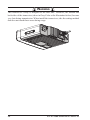
1
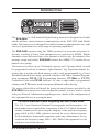
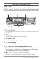
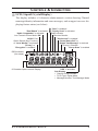
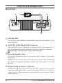
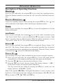
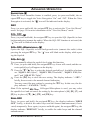
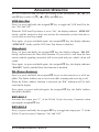
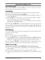
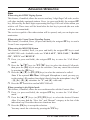
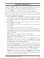
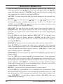
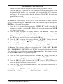
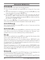
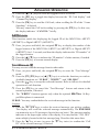
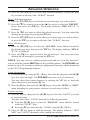
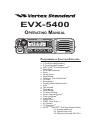
EVX-5400 Operating Manual Programmable Functions/Features 6 Programmable Function Keys 2-Tone Encode/Decodeø1 5-Tone Encode/Decodeø1 MDC-1200® Encode/Decodeø1 Horn Alert PA (Public Address) Scan Group Scan Dual Watch FM-Scan (Follow-Me Scan) TA Scan Encryptionø1 Privacy (Basic/Enhanced)ø2 VOX Talk Around Emergency Lone Worker TX Save Disable Direct Channel Entryø3 Code Up/Downø1 Code Setø1 Speed Dialø1 DTMF Code Setø1, 3 ID Checkø1 TX Messageø1 ARTSTMø1/ARTSIITM (Auto Range Transpond System) ø1: Analog mode only ø2: Digital mode only ø3: Requires Optional MH-75A8J Congratulations! You now have at your fingertips a valuable communications tool: a Vertex Standard two-way radio! Rugged, reliable and easy to use, your Vertex Standard radio will keep you in constant touch with your colleagues for years to come, with negligible maintenance downtime. Please take a few minutes to read this manual carefully. The information presented here will allow you to derive maximum performance from your radio. We’re glad you joined the Vertex Standard team. Call on us anytime, because communications is our business. Let us help you get your message across. Notice ! There are no owner-serviceable parts inside the transceiver. All service jobs must be referred to an authorized Vertex Standard Service Representative. Consult your Authorized Vertex Standard dealer for installation of optional accessories. Safety/Warning Information WARNING - DO NOT operate the EVX-5400 radio when any person(s) (bystanders) outside the vehicle are within the distances shown in the chart at the bottom of this section. Safety Training information: Antennas used for this transmitter must not exceed an antenna gain of 0 dBi. The radio must be used in vehicle-mount configurations with a maximum operating duty cycle not exceeding 50 %, in typical Push-to-Talk configurations. This radio is restricted to occupational use, work related operations only where the radio operator must have the knowledge to control the exposure limits of passengers and bystanders by maintaining the minimum separation distance shown below. Failure to observe these restrictions will result in exceeding the FCC RF exposure limits. Antenna Installation: For rear deck trunk installation, the antenna must be located at least the following distance away from rear-seat passengers in order to comply with the FCC RF exposure requirements. For roof top installations, the antenna must be placed in the center of the roof. Unsafe Radiation Distance VHF Model 2.9 Feet (0.89 m) UHF Model 2.1 Feet (0.64 m) Introduction The EVX-5400 is a full-featured Digital/Analog transceiver designed for flexible mobile and base station business communications in the VHF/UHF Land Mobile bands. This transceiver is designed for reliable business communications in a wide variety of applications for a wide range of operating capabilities. The EVX-5400 operates using the TDMA protocol for spectrum and power efficiency resulting in lower total equipment cost compared to FDMA. Digital eliminates noise and static from voice transmit to deliver only the intended voice message crisply and clearly. EVX-5400 features the AMBE+2™ vocoder for enhanced voice quality. This transceiver allows up to 512-channel capacity and 32 groups which can each be programmed with an 8-character Alpha-Numeric Tag. Important channel frequency data is stored in the flash memory, and is easily programmable by a Vertex Standard licensed dealer using a personal computer with Vertex Standard Programming equipment: FIF-12 USB Programming Interface, CT-104A (or CT-171) Connection Cable with CE142 Software. Or, once a single radio is programmed, cloning cable CT-4 can be used to program additional radios directly. The pages which follow will detail the many advanced features provided by the EVX-5400 Series transceiver. After reading this manual, you may wish to consult with your Network Administrator regarding precise details of the configuration of this equipment for use in your application. For North American Users Regarding 406 MHz Guard Band The U.S. Coast Guard and National Oceanographic and Atmospheric Administration have requested the cooperation of the U.S. Federal Communications Commission in preserving the integrity of the protected frequency range 406.0 to 406.1 MHz, which is reserved for use by distress beacons. Do not attempt to program this apparatus, under any circumstances, for operation in the frequency range 406.0 - 406.1 MHz if the apparatus is to be used in or near North America. EVX-5400 Operating Manual 1 Warning! FCC RF Exposure Requirements THIS DEVICE COMPLIES WITH PART 15 OF THE FCC RULES. OPERATION IS SUBJECT TO THE FOLLOWING TWO CONDITIONS: (1) THIS DEVICE MAY NOT CAUSE HARMFUL INTERFERENCE, AND (2) THIS DEVICE MUST ACCEPT ANY INTERFERENCE RECEIVED, INCLUDING INTERFERENCE THAT MAY CAUSE UNDESIRED OPERATION. THE GRANTEE IS NOT RESPONSIBLE FOR ANY CHANGES OR MODIFICATIONS NOT EXPRESSLY APPROVED BY THE PARTY RESPONSIBLE FOR COMPLIANCE. SUCH MODIFICATIONS COULD VOID THE USER’S AUTHORITY TO OPERATE THE EQUIPMENT. This equipment has been tested and found to comply with the limits for a Class B digital device, pursuant to part 15 of the FCC Rules. These limits are designed to provide reasonable protection against harmful interference in a residential installation. This equipment generates, uses and can radiate radio frequency energy and, if not installed and used in accordance with the instructions, may cause harmful interference to radio communications. However, there is no guarantee that interference will not occur in a particular installation. If this equipment does cause harmful interference to radio or television reception, which can be determined by turning the equipment off and on, the user is encouraged to try to correct the interference by one or more of the following measures: r Reorient or relocate the receiving antenna. r Increase the separation between the equipment and receiver. r Connect the equipment into an outlet on a circuit different from that to which the receiver is connected. r Consult the dealer or an experienced radio/TV technician for help. 2 EVX-5400 Operating Manual Warning! IC RSS General Requirements English r This device complies with Industry Canada license-exempt RSS standard(s). Operation is subject to the following two conditions: (1) this device may not cause interference, and (2) this device must accept any interference, including interference that may cause undesired operation of the device. r Under Industry Canada regulations, this radio transmitter may only operate using an antenna of a type and maximum (or lesser) gain approved for the transmitter by Industry Canada. To reduce potential radio interference to other users, the antenna type and its gain should be so chosen that the equivalent isotropically radiated power (e.i.r.p.) is not more than that necessary for successful communication. r Antennas used for this transmitter (identify the device by certification number, or model number if Category II) must not exceed an antenna gain of 0 dBi. The radio must be used in vehicle-mount configurations with a maximum operating duty cycle not exceeding 50 %, in typical Push-to-Talk configurations. Antenna types having a gain greater than 0 dBi are strictly prohibited for use with this device. French r Le présent appareil est conforme aux CNR d’Industrie Canada applicables aux appareils radio exempts de licence. L’exploitation est autorisée aux deux conditions suivantes: (1) l’appareil ne doit pas produire de brouillage, et (2) l’utilisateur de l’appareil doit accepter tout brouillage radioélectrique subi, même si le brouillage est susceptible d’en compromettre le fonctionnement. Conformément à la réglementation d’Industrie Canada, le présent émetteur rar dio peut fonctionner avec une antenne d’un type et d’un gain maximal (ou inférieur) approuvé pour l’émetteur par Industrie Canada. Dans le but de réduire les risques de brouillage radioélectrique à l’intention des autres utilisateurs, il faut choisir le type d’antenne et son gain de sorte que la puissance isotrope rayonnée quivalente (p.i.r.e.) ne dépassepas l’intensité nécessaire à l’établissement d’une communication satisfaisante. r Antennes utilisées pour cet émetteur (identifier le dispositif par son numéro de certification ou son numéro de modèle s’il fait partie du matériel de catégorie II) ne doit pas dépasser un gain de l’antenne de 0 dBi. La radio doit être utilisée dans des configurations de montage en véhicule avec un maximum d’utilisation en fonctionnement n’excédant ne pas 50 %, dans des configurations typiques de Push-to-Talk. Types d’antenne ayant un gain supérieur à 0 dBi sont strictement interdits pour une tilisation avec cet appareil. EVX-5400 Operating Manual 3 Controls & Connectors Front Panel Important! - All buttons located on the Front Panel are Programmable Function (PF) keys, configured according to your network requirements and programmed by your Vertex Standard dealer. The instructions below describe a typically-configured radio. PWR ( ) Button Press and hold in this button for 2 seconds to toggle the transceiver’s power “on” and “off”. VOL Knob Turn this control clockwise to increase the volume. Microphone Jack Connect the microphone plug to this jack. TX/BUSY Indicator Indicates transceiver’s Transmit/Receive Status. [P1] - [P4] Keys (Programmable Function Keys) These keys can be set up for special applications, such as High/Low power selection, Monitor, Talk-Around, etc., as determined by your network requirements and programmed by your Vertex Standard dealer. []/[] Keys (Programmable Function Keys) 4 In the factory default, pressing either key changes the current channel. EVX-5400 Operating Manual Controls & Connectors LCD (Liquid Crystal Display) The display includes a 8-character alpha-numeric section showing Channel nametags/identity information and error messages, and an upper icon row displaying feature status (see below). “Dual Watch” is activated “Audio Compander” is activated Low Transmit Power Mode “ON” “AUX A” Port, Option Switch (Key Function), or “Lone Worker” is activated “Privacy” or “Encryption” is enabled : “Scan” is enabled : “Priority Scan” is activated “Call” indicator Receiver Monitor “Talk-Around” is enabled “5-tone Status Call” or “Digital Text Message” is received Priority-2 Channel “Group Scan” is enabled RSSI Indicator (four steps) 8 Character Alpha-numeric Display EVX-5400 Operating Manual “VOX” is activated Sub Display Channel Group Number TX ID Type: Digital Mode Message Number: Text Message Mode 5 Controls & Connectors Rear Panel Antenna Jack The 50-Ohm coaxial feedline to the antenna must be connected here, using a mini-UHF plug. 13.6V DC Cable Pigtail with Connector The supplied DC power cable must be connected to this 2-pin connector. Use only the supplied fused cable, extended if necessary, for power connection. Replace only with the same or equivalent type fuse. External Speaker Jack An external loudspeaker may be connected to this 2-contact, 3.5-mm miniphone jack. Caution: Do not connect either wire of this line to ground, and be certain that the speaker has adequate capability to handle the audio output (12 W) from the radio. D-Sub 15-Pin Accessory Connector 6 External TX audio line input, PTT (Push To Talk), Squelch, and external RX audio line output signals may be obtained from this connector for use with accessories such as data transmission/reception modems, and external Channel control input, etc. EVX-5400 Operating Manual Basic Operation Important! - Before turning on the radio the first time, confirm that the power connections have been made correctly and that a proper antenna is connected to the antenna jack. Switching Power ON/OFF Press and hold in the PWR( ) button for 2 seconds to turn the radio on. The channel number indicator will indicate the operating channel. Press the []/[] key to choose the desired operating channel. A channel name will appear on the display. The radio announces the channel number if the Channel Announcement Feature is enabled via the PC programming software. If you want to select an operating channel from a different group, press the PF key which is programmed to the Group Up/Down feature to select the group you want before selecting the operating channel. See page 9 for more information of the Programmable Function keys. Setting the Volume Turn the VOL knob clockwise to increase the volume and counterclockwise to decrease it. Transmitting To transmit, monitor the channel and make sure it is clear. If no signal is present on the analog channel, press the PF key which is programmed to the Monitor feature to listen for channel activity. When receiving a call, transmit only after the incoming call ends. The radio cannot receive a call and transmit simultaneously. Press the PTT switch. If the channel is clear, the TX/BUSY indicator will glow red (on the Analog Channel) or blue (on the Digital Channel). The radio is now transmitting. While holding in the PTT switch, speak across the face of the microphone in a clear and normal voice. For best transmission, hold the microphone about 1-1/2 to 2 inches (4 ~ 5 cm) away from your mouth. Release the PTT switch to receive. If the BCLO (Busy Channel Lockout) feature has been programmed on an analog channel, the radio will not transmit when a carrier is present. Instead, the radio will generate short beep three times. Release the PTT switch and wait for the channel to be clear of activity. If the BTLO (Busy Tone Lockout) feature has been programmed on an analog channel or CCLO (Color Code Lockout) feature has been programmed on a digital channel, the radio can transmit only when there is no carrier being received or when the carrier being received includes the correct tone (CTCSS tone or DCS code) on an analog channel or correct code on a digital channel. EVX-5400 Operating Manual 7 Basic Operation Transmit Time-Out Timer If the selected channel has been programmed for automatic time-out, you must limit the length of each transmission. While transmitting, a beep will sound 10 seconds before time-out. Another beep will sound just before the deadline; the red “TX” indicator will disappear and transmission will cease soon thereafter. To resume transmitting, you must release the PTT switch and wait for the “penalty timer” to expire (if you press the PTT switch before this timer expires, the timer restarts, and you will have to wait another “penalty” period). Key Lock In order to prevent accidental operating function/feature change or inadvertent transmission, various aspects of the front panel’s keys may be locked out. To activate the Locking feature, press and hold in the [P1] key while turning the radio on. To disable the Locking feature, repeat this power-on procedure. 8 EVX-5400 Operating Manual Advanced Operation Programmable Function (PF) Keys The EVX-5400 Series includes six Programmable Function (PF) keys. These PF keys can be customized, via programming by your Vertex Standard dealer, to meet your communications/network requirements. The possible PF key programming features are illustrated on the next page, and these functions are explained beginning after page 12. For further details, contact your Vertex Standard dealer. In this chapter, the following icons are used to indicate features supported in either the “Analog” mode or “Digital” mode: : Indicates a “Analog” mode only feature. : Indicates a “Digital” mode only feature. For features that are available in both “Analog” and “Digital” modes, no icon is shown. For future reference, check the box next to each function that has been assigned to the PF key on your particular radio and keep it handy. EVX-5400 Operating Manual 9 Advanced Operation Function None Monitor Monitor -MomentarilyDimmer Low Power Privacy/Encryption Privacy Set SET SQL OFF SQL OFF -MomentarilySQL Set Beep OFF AF Minimum Volume CH Announcement Whisper VOX VOX Set VOX Anti-Trip Horn Alert PA (Public Address) EXT ACC 1 EXT ACC 2 Emergency Lone Worker Group Up Group Down Channel Up Channel Down Speed CH Up Speed CH Down PRI-1 PRI-2 PRI-2 Set PRI-2 Disable Direct CH 1 Direct CH 2 Direct CH 3 Direct CH 4 Direct CH Entryø Scan Group Scan Dual Watch FM-Scan Scan Set Group Scan Set TA Scan Talk Around 10 Programmable Key (Press Key/Press & Hold Key) Microphone Key (Press Key/Press & Hold Key) Ü A B C D # P1 P2 P3 P4 p q / / / / / / / / / / / / / /-/ / / / / / /-/ / / / / / / / / / /-/ /-/ / / / / --/ --/ / / / / / / / / --/-/ / / / / / / / / /-/ / / / / / /-/ / / / / / / / / / /-/ /-/ / / / / --/ --/ / / / / / / / / --/-/ / / / / / / / / /-/ / / / / / /-/ / / / / / / / / / /-/ /-/ / / / / --/ --/ / / / / / / / / --/-/ / / / / / / / / /-/ / / / / / /-/ / / / / / / / / / /-/ /-/ / / / / --/ --/ / / / / / / / / --/-/ / / / / / / / / /-/ / / / / / /-/ / / / / / / / / / /-/ /-/ / / / / --/ --/ / / / / / / / / --/-/ / / / / / / / / /-/ / / / / / /-/ / / / / / / / / / /-/ /-/ / / / / --/ --/ / / / / / / / / --/-/ / / / / / / / / /-/ / / / / / /-/ / / / / / / / / / /-/ /-/ / / / / --/ --/ / / / / / / / / / / / / / / / / / / /-/ / / / / / /-/ / / / / / / / / / /-/ /-/ / / / / --/ --/ / / / / / / / / / / / / / / / / / / /-/ / / / / / /-/ / / / / / / / / / /-/ /-/ / / / / --/ --/ / / / / / / / / / / / / / / / / / / /-/ / / / / / /-/ / / / / / / / / / /-/ /-/ / / / / --/ --/ / / / / / / / / / / / / / / / / / / /-/ / / / / / /-/ / / / / / / / / / /-/ /-/ / / / / --/ --/ / / / / / / / / / / / / / / / / / / /-/ / / / / / /-/ / / / / / / / / / /-/ /-/ / / / / --/ --/ / / / / / / / / / / / / / / / / / EVX-5400 Operating Manual Advanced Operation Function Reset CALL 1 CALL 2 CALL 3 CALL 4 CALL 5 Code Up Code Down Code Set Speed Dial DTMF Code Setø Call Status Set Status Up Status Down Status Check Duty Programmable Key (Press Key/Press & Hold Key) Microphone Key (Press Key/Press & Hold Key) Ü A B C D # / / / / / / / / / / / / / / / / / / / / / / / / / / / / / / / / / / / / P1 / / / / / / P2 / / / / / / P3 / / / / / / P4 / / / / / / p / / / / / / q / / / / / / / / / / / / / / / / / / / / / --/-/ / / / / / / / --/-/ / / / / / / / --/-/ / / / / / / / --/-/ / / / / / / / --/-/ / / / / / / / --/-/ / / / / / / / / / / / / / / / / / / / / / / / / / / / / / / / / / / / / / / / / / / / / / / / / / / / / / / / / / / / / / / / / / / / / / / / / / /-/ / / / / / /-/ / / / / / /-/ / / / / / /-/ / / / / / /-/ / / / / / /-/ / / / / / /-/ / / / / / /-/ / / / / / /-/ / / ID Check / / / ARTS Login / / / TEXT Message / / / Option SW1 /-/-/-Option SW2 / / / TX Save Disable / / / Lock / / / : Requires the optional MH-75A8J Microphone. EVX-5400 Operating Manual 11 Advanced Operation Description of Operating Functions Monitor Press, (or press and hold), the assigned PF key to cancel any signaling features. When the Monitor function is activated, the “ ” icon will be indicated on the display. Monitor -Momentarily- Cancel any signaling features while pressing the assigned PF key. The “ ” icon will be indicated on the display while canceling any signaling features. Dimmer Press, (or press and hold), the assigned PF key to select the brightness level of the display and keypad. Low Power Press, (or press and hold), the assigned PF key to set the radio’s transmitter to the “Low Power” mode. Press, (or press and hold), the PF key again to return to “High Power” operation when in difficult terrain. When the radio’s transmitter is set to “Low Power” mode, the “L” icon will be indicated on the display. Privacy Press, (or press and hold), the assigned PF key to toggle the Privacy feature “On” and “Off”. The Privacy feature initiates an encryption algorithm that will protect your communication from unauthorized eavesdropping. When the Privacy feature is activated, the “ ” icon will be indicated on the display. Privacy Set You can change a Privacy Code to maintain the best security using this function: Press, (or press and hold), the assigned PF key. A tone will sound, and the current Privacy Code number and its tag name will appear on the display. Press the []/[] key to select the desired Privacy Code. Press the [P4] key to store the new setting. The display indicates “- SET -” briefly, then reverts to the normal channel indication. You may cancel the new setting by pressing the [P3] key. In this case, the display indicates “-CANCEL-” briefly. Note: If the optional MH-75A8J 16-Keypad Microphone is used, you may select the Privacy Code and set/cancel the setting by the microphone’s [A], [B], [C], and [D] key in place of [], [], [P3], and [P4] key. 12 EVX-5400 Operating Manual Advanced Operation Encryption When the Voice Scrambler feature is enabled, press, (or press and hold), the assigned PF key to toggle the Voice Encryption “On” and “Off”. When the Voice Encryption is activated, the “ ” icon will be indicated on the display. SET Press, (or press and hold), the assigned PF key to activate the “User Set (Menu)” mode. See page 32 for more information of the “User Set (Menu)” mode. SQL OFF Press, (or press and hold), the assigned PF key to open the SQL (Squelch) to hear background noise (unmute the audio). When the SQL OFF function is activated, the “ ” icon will be blinked on the display. SQL OFF -Momentarily- Opens the SQL (Squelch) to hear background noise (unmute the audio) when pressing the assigned PF key. The “ ” icon will blink on the display while opening the Squelch. SQL Set You can manually adjust the squelch level using this function: Press, (or press and hold), the assigned PF key. A tone will sound, and the current squelch level will appear on the display. Press the []/[] key to select the desired squelch level. Available selections are “SQLLV OP (Open)”, “SQLLV TH (Threshold)”, “SQLLV NM (Normal)” and “SQLLV TI (Tight)”. Press the [P4] key to store the new setting. The display indicates “- SET -” briefly, then reverts to the normal channel indication. You may cancel the new setting by pressing the [P3] key. In this case, the display indicates “- CANCEL -” briefly. Note: If the optional MH-75A8J 16-Keypad Microphone is used, you may select the squelch level and set/cancel the setting by the microphone’s [A], [B], [C], and [D] key in place of [], [], [P3], and [P4] key. Beep OFF Press, (or press and hold), the assigned PF key, the display indicates “BEEP OFF” briefly, to disable the radio beeps and the channel announcement (if activated) temporarily. Press again, (or press and hold again), the assigned PF key, the display indicates “BEEP ON” briefly, to enable the radio beeps and the channel announcement. EVX-5400 Operating Manual 13 Advanced Operation AF Minimum Volume Press, (or press and hold), the assigned PF key, the display indicates “AFATT ON” briefly, and reduce the audio output to the (lower) level programmed. Again press, (or press and hold), the assigned PF key, the display indicates “AFATT OF” briefly, and resume normal audio output level. You may change the programmed (lower) level by the “User Set (Menu)” mode. See page 32 for more information. CH Announcement Press, (or press and hold), the assigned PF key to select the channel change confirmation between “beep” (indicates “BEEP” briefly) and “announcement” (indicates “ANNOUNCE” briefly). Whisper Press, (or press and hold), the assigned PF key, the display indicates “WHISP ON” briefly, and increase the microphone gain; allowing you to speak in a low voice (whisper) temporarily. Press again, (or press and hold again), the assigned PF key, the display indicates “WHISP OF” briefly, and resume normal microphone gain. VOX Press, (or press and hold), the assigned PF key, the display indicates “VOX O.N” briefly, and activates the VOX function; allowing hands-free, automatic activation of the transmitter, based on voice input into the microphone. When the VOX function is activated, a small dot (“.”) will be indicated at the bottom right of the display. You may disable the VOX function temporarily by pressing the PTT switch. Press again, (or press and hold again), the assigned PF key, the display indicates “VOX OFF” briefly, and resume normal operation. VOX Set You can manually adjust the VOX Gain using this function: Press, (or press and hold), the assigned PF key. A tone will sound, and the current VOX Gain level will appear on the display. Press the []/[] key to select the desired VOX Gain level. Available selections are “VOXLV –8” to “VOXLV +8”. Press the [P4] key to store the new setting. The display indicates “- SET -” briefly, then reverts to the normal channel indication. You may cancel the new setting by pressing the [P3] key. In this case, the display indicates “- CANCEL -” briefly. Note: If the optional MH-75A8J 16-Keypad Microphone is used, you may select 14 EVX-5400 Operating Manual Advanced Operation the VOX Gain level and set/cancel the setting by the microphone’s [A], [B], [C], and [D] key in place of [], [], [P3], and [P4] key. VOX Anti-Trip Press, (or press and hold), the assigned PF key to toggle the VOX Anti-Trip feature “On” and “Off”. When the VOX Anti-Trip feature is set to “On”, the display indicates “ATRP ON” briefly, and the transceiver does not activate the transmitter section from the receiver audio or own beep sound. Press again, (or press and hold again), the assigned PF key, the display indicates “ATRP OFF” briefly, and the VOX Anti-Trip feature is disabled. Horn Alert Press, (or press and hold), the assigned PF key, the display indicates “HA ON” briefly, and activates the Horn Alert function. If you receive a call from the base station with the signaling, horn alert will be activated and your vehicle’s horn will sound. Press again, (or press and hold again), the assigned PF key, the display indicates “HA OFF” briefly, and the Horn Alert function is disabled. PA (Public Address) Press, (or press and hold), the assigned PF key to use the transceiver as a PA amplifier. The Public Address can be used even while scanning and receiving a call. When the Public Address function is activated, the “PA” indication will be indicated on the display. Press again, (or press and hold again), the assigned PF key, the Public Address function is disabled. EXT ACC 1 Activates the output port “1” of the D-Sub 15-pin Accessory Connector when pressing the assigned PF key. EXT ACC 2 Press, (or press and hold), the assigned PF key to toggle the output port “2” of the D-Sub 15-pin Accessory Connector “On” and “Off”. EVX-5400 Operating Manual 15 Advanced Operation Emergency The EVX-5400 series includes an “Emergency” feature in either analog or digital modes, which may be useful for alerting another party assistance may be required, when monitoring the same frequency as your transceiver’s channel. Press and hold the assigned PF key, the “- EMG -” indication will be indicated on the display, and initiate an emergency call on the pre-defined channel. For further details contact your Vertex Standard dealer. To revive the radio from the Emergency mode, just press and hold again the assigned PF key or turn off the radio. Lone Worker Press, (or press and hold), the assigned PF key, the display indicates “L-WK ON” briefly, and activates the Lone Worker feature. The Lone Worker feature is designed to emit an alarm for 30 seconds when the Lone Worker Timer (programmed by your Vertex Standard dealer) has expired. Press again, (or press and hold again), the assigned PF key, the display indicates “L-WK OFF” briefly, and the Lone Worker feature is disabled. If the user does not reset the timer by pressing the PTT switch, the radio switches to Emergency mode. Group Up/Down Press, (or press and hold), the assigned PF key to select a different group of channels. A group name will appear briefly on the display. CH Up/Down Press, (or press and hold), the assigned PF key (generally the []/[] key) to select a different channel. A channel name will appear briefly on the display. Speed CH Up/Down Press and hold the assigned PF key causes the radio to begin stepping (repeatedly) upward or downward through the channels. PRI-1 Press, (or press and hold), the assigned PF key to recall the pre-programmed Priority Channel (Priority-1) by your Vertex Standard dealer directly. When PRI-1 channel is recalled, the “P1” will appear at the upper right corner on the display. 16 EVX-5400 Operating Manual Advanced Operation PRI-2 Press, (or press and hold), the assigned PF key to recall the pre-programmed Priority Channel of the current group (Priority-2) by your Vertex Standard dealer directly. When PRI-2 channel is recalled, the “P” icon will be indicated on the display. PRI-2 Set Press, (or press and hold), the assigned PF key to toggle the current channel to the priority channel 2 “enable” and “disable”. When PRI-2 channel is recalled, the “P” icon will be indicated on the display. PRI-2 Disable Press, (or press and hold), the assigned PF key, the display indicates “PRI2 DI” briefly, and disable the priority channel 2 of the group temporarily. Press again, (or press and hold again), the assigned PF key, the display indicates “PRI2 EN” briefly, and enabling the priority channel 2 of the group. Direct CH 1 to Direct CH 4 Press, (or press and hold), the assigned PF key to recall the pre-programmed channel by your Vertex Standard dealer directly. Direct CH Entry (This function requires the Optional MH-75A8J 16-Keypad Microphone) You can call the desired channel directly using this function: Press, (or press and hold), the assigned PF key. A tone will sound, and the current group/channel will appear on the display. Enter the desired group number (two digits) and channel number (three digits) from the microphone’s numeric ([0] - [9]) key. Press the microphone’s [D] key to call the designated channel. You may cancel this function by pressing the microphone’s [C] key. In this case, the display indicates “- CANCEL -” briefly. Note: You may recall and cancel the setting by the [P3] (for cancel) and [P4] (for recall) key. EVX-5400 Operating Manual 17 Advanced Operation Scan The Scanning feature is used to monitor multiple channels programmed into the transceiver. While scanning, the transceiver will check each channel for the presence of a signal and will stop on a channel if a signal is present. EVX-5400 series can scan both digital and analog frequency programmed channels simultaneously. To activate scanning: Press, (or press and hold), the assigned PF key to activate scanning. The scanner will search the channels in the scan list, looking for a transmitting channel. The Scan function will pause each time it finds a channel on which someone is speaking. Press, (or press and hold), the assigned PF key again to disable scanning, and receive the channel which was chosen when pressed the PF key. Note: Your Vertex Standard dealer may have programmed your radio to stay on one of the following channels if you press the PTT switch during the scanning pause: o “Scan Pause” channel (“Talk Back”) o “Last Busy” channel o “Priority-1” channel o “Priority-2” channel o “User Programmed” channel (“Select Channel”) o “Scan Start” channel Group Scan The Scanning feature is used to monitor multiple channels programmed into the transceiver. While scanning, the radio will check each channel of the programmed group for the presence of the signal, and will stop on a channel if a signal is present. Press, (or press and hold), the assigned PF key, the display indicates “GRP SCAN” briefly, and activate the scanning on the selected groups. Press again, (or press and hold again), the assigned PF key to disable the group scan mode, and receive the channel which was chosen when pressed the PF key. Dual Watch The Dual Watch feature is similar to the SCAN feature, except that only two channels are monitored: o The current operating channel; and o The Priority-2 channel. To activate Dual Watch: Press, (or press and hold), the assigned PF key. the “DW” icon will be indi- 18 EVX-5400 Operating Manual Advanced Operation cated on the display. The scanner will search the two channels and pause each time it finds a channel on which someone is speaking. To stop Dual Watch: Press, (or press and hold), the assigned PF key. the “DW” icon disappear from the display. The radio receives the channel which was chosen when pressed the PF key. FM-Scan (Follow-Me Scan) The FM-Scan feature checks a user-assigned priority channel regularly as you scan the other channels. Thus, if only Channels 1, 3, and 5 (of the 8 available channels) are designated for “scanning”, the user may assign Channel 2 as the “user-assigned” priority channel via FM-Scan. To activate FM-Scan, first select the channel you want to designate as the “userassigned priority channel” and press, (or press and hold), the assigned PF key. The display indicates “FM SCAN” briefly. Then press, (or press and hold), the Channel Up/Down key (generally the [ ]/[ ] key) to recall to the “Scanning Start” channel which has been programmed by your dealer to activate the scanner. When the scanner stops on an “Active” channel, the user-assigned priority channel will automatically be checked every few seconds. If activity is found on the userassigned priority channel, the radio will switch between it and the dealer-assigned priority channel, if any. Scan Set Press, (or press and hold), the assigned PF key to add/delete the current channel to/from your scanning list. To store a particular channel to your scanning list, press, (or press and hold), the assigned PF key; the display indicates “SCN SET” briefly and “ ” icon will appear on the display. If you delete a channel from your scanning list, press, (or press and hold), the assigned PF key again; the display indicates “SCN SKIP” briefly and the “ ” icon will disappear from the display. When the scanner is paused, you may remove the channel from the scan list temporarily by pressing, (or press and holding), the same key. Group Scan Set You may wish to have the Scanner pass through more than one Group during the scanning process (normally, scanning is performed within the current group only). To include the current Group in the scanning loop, press, (or press and hold), the EVX-5400 Operating Manual 19 Advanced Operation assigned PF key (the “” icon will appear on the display). To remove a current Group from Group Scan, press, (or press and hold), the assigned PF key again (the “” icon will disappear from the display). TA Scan Press, (or press and hold), the assigned PF key to toggle the TA (Talk Around) scan feature “On” and “Off.” While TA scan is enabled, the transceiver will search both the transmit and receive frequencies (the “ ” icon will blink on the display). When a signal is encountered on the receive frequency, the transceiver will pause until the signal disappears (the “ ” icon will appear but not blink on the display). When a signal is encountered on the transmit frequency, the transceiver will check for activity on the receive frequency every few seconds (interval programmed by your Vertex Standard dealer). Note: The TA Scan feature does not activate on a Simplex Channel. Talk Around Press, (or press and hold), the assigned PF key to activate the Talk Around feature when you are operating on duplex channel systems (separate receive and transmit frequencies, utilizing a “repeater” station). The Talk Around feature allows you to bypass the repeater station and talk directly to a station that is nearby. This feature has no effect when you are operating on “simplex” channels, as the receive and transmit frequencies are already the same. When the Talk Around feature is activated, the “ ” icon will be indicated on the display. Note that your Vertex Standard dealer may have made provision for “Talk Around” channels by programming “repeater” and “Talk Around” frequencies on two adjacent channels. If so, the key may be used for one of the other Pre-Programmed Functions. Note: The Talk Around feature does not activate on a Simplex Channel. Reset Press, (or press and hold), the assigned PF key to reset the RFC (Ready for Communication) condition. Call 1 to Call 5 Press, (or press and hold), the assigned PF key to send a pre-programmed call signal of the 2-Tone, 5-Tone, MDC1200® or Digital Call. 20 EVX-5400 Operating Manual Advanced Operation Code Up/Down Press, (or press and hold), the assigned PF key to select a 2-Tone or 5-Tone encode code from the pre-programmed encode list. Code Set You can change the desired digit of the 5-Tone encode code using this function: Press, (or press and hold), the assigned PF key. Select the desired digit using the [P1]/[P2] keys, then change the number using the []/[] keys. Press the [P4] key to store the new setting. The display indicates “- SET -” briefly, then reverts to the normal channel indication. You may cancel the new setting by pressing the [P3] key. In this case, the display indicates “-CANCEL-” briefly. Note: If the optional MH-75A8J 16-Keypad Microphone is used, you may enter the 5-Tone encoding code directly from the microphone’s numeric ([0] - [9]) key. In this case, you may set and cancel the setting by the microphone’s [C] (for cancel) and [D] (for set) key. Speed Dial Your Vertex Standard dealer may have pre-programmed Auto-Dial telephone number memories into your radio. To dial a number: Press, (or press and hold), the assigned PF key. Press the []/[] keys to select the Auto-Dial memory number which is preprogrammed by your Vertex Standard dealer, then press the PTT switch. The DTMF tones sent during the dialing sequence will be heard in the speaker. Note: If the optional MH-75A8J 16-Keypad Microphone is used, you may select the Auto-Dial memory number by the microphone’s numeric ([0] - [9]) key. DTMF Code Set (This function requires the Optional MH-75A8J 16-Keypad Microphone) Press, (or press and hold), the assigned PF key to start entering the DTMF dialing sequence. Enter the DTMF digit from the microphone’s numeric ([0] - [9]) key. After entering all DTMF digits, press the PTT switch to transmit the DTMF code. EVX-5400 Operating Manual 21 Advanced Operation Call When using the DTMF Paging System This feature, if enabled, allows the user to send any 3-digit Page Call code, used to call other similarly-equipped stations. Press, (or press and hold), the assigned PF key, followed by the three digits representing the Page Call code of the station you wish to call. Three tones will be heard after the last key is pressed (the new code will now be transmitted). The receiver squelch of the other station will be opened, and you can begin communication. When using the 2-tone/5-tone Signaling System This feature, if enabled, Press, (or press and hold), the assigned PF key to send a 2-tone/5-tone sequential tone. When using the MDC1200 System This feature, if enabled, Press, (or press and hold), the assigned PF key to send an MDC1200 code. Available codes are “CALL ALT”, “SEL CALL”, “RADIO CH”, “STUN” and “REVIVE”. Press, (or press and hold), the assigned PF key to enter the “Call Menu” mode. Press the []/[] keys (or [P1]/[P2] keys) to select the desired Call mode, then press the [P4] key to accept the selection. (You may cancel the selection by pressing the [P3] key). Press the []/[] (or [P1]/[P2] keys) to select the station to be called. Note: If the optional MH-75A8J 16-Keypad Microphone is used, you may enter the station’s ID number (four digits) directly from the microphone’s key ([0] - [9], [A] - [D], [#]: substitute for “E”, and [Ý]: wild card). Press the PTT switch to send an MDC1200 call. When operating in the Digital mode This feature, if enabled, allows the user confirm and/or edit the Contact Alias. Press, (or press and hold), the assigned PF key to enter the “Call Menu” mode. Press the [ ]/[ ] keys (or [P1]/[P2] keys) to select the desired Contact Alias. You may find the “New List” and “Manual” category at the last of the indication loop. Describes these two functions later. Press the [P4] key to accept the selection. You may cancel the selection by pressing the [P3] key. 22 EVX-5400 Operating Manual Advanced Operation I) If the TX ID Type of the selected Contact Alias is “Group Call” or “All Call” (indicates the “GC” or “AC” icon at the upper right corner of the display), you may confirm the Call ID of the Contact Alias by the following operation: Press the [P4] key to confirm the “Call ID” of the selected Contact Alias. Press the [P3] key to return the display to the “Tag Name” indication. II) If the TX ID Type of the selected Contact Alias is “Private Call” (indicates the “PC” icon at the upper right corner of the display), you may confirm and edit the Contact Alias by the following operation: Press the []/[] keys (or [P1]/[P2] keys) to select the function you wish to. Available selections are “CALL ALT”, “VIEW ID”, “EDIT TAG”, “EDIT ID”, “ALT SEL”, “DEL LIST”, “RADIO CK”, “RADIOMON”, “REVIVE” and “STUN”. Press the [P4] key to accept the selected function. Refer to follows for detailed operation of each function. Press the [P3] key to cancel the “Call” feature and return to the normal operation, if desired. CALL ALT: You may contact with the selected Contact Alias. Press the [P4] key to transmit the call alert command to the designated radio. If the designated radio is active, the designated radio transmits the ACK command and displays your ID number on the display. If not, your radio’s display indicates “NO ACK”. VIEW ID: You may confirm the Call ID of the Contact Alias. Press the [P4] key to confirm the “Call ID”. Press the [P3] key to return the display to the “Tag Name” indication. EDIT TAG: You may edit the “Tag Name” of the selected Contact Alias. Important Note: This function require the optional MH-75A8J 16-Keypad Microphone, and you can not edit the “Tag Name” of the Contact Alias which determined by the CE142 Programming Software. Press the [P4] key, then edit the “Tag Name” using the [0] - [9] key (for select the character) and [A]/[B] key (for select the digit). You may delete the current character by pressing the [Ý] key, or insert the space by pressing the [#] key. Press the [P4] key again, the display indicates “-SAVED-” briefly and store the new setting. You may cancel the new setting by pressing the [P3] key. EDIT ID: You may edit the “ID number” of the selected Contact Alias. Important Note: This function require the optional MH-75A8J 16-Keypad Microphone, and you can not edit the “ID number” of the contact number which determined by the CE142 Programming Software. EVX-5400 Operating Manual 23 Advanced Operation Press the [P4] key, then edit the “ID number” using the [0] - [9] key (for select the number) and [A]/[B] key (for select the digit). Press the [P4] key again, the display indicates “-SAVED-” briefly and store the new setting. You may cancel the new setting by pressing the [P3] key. ALT SEL: You may change the alert tone which assigned to the selected Contact Alias. Press the [P4] key, then press the []/[] keys (or [P1]/[P2] keys) to select the desired alert tone. Available selections are “TONE A” to “TONE J” and “NONE”. Press the [P4] key again to store the new setting. You may cancel the new setting by pressing the [P3] key. DEL LIST: You may delete the desired Contact Alias from the contact list. Important Note: The deleted Contact Alias can not be restored, and you can not delete the Contact Alias which determined by the CE142 Programming Software. Press the [P4] key, the display indicates “DEL Y/N”(“Y” is blinking). Press the [P4] key again, the display indicates “-SAVED-” briefly, then reverts to first contact number of the contact list. You may cancel the new setting by pressing the [P3] key. RADIO CK: You may check the radio status of the selected Contact Alias. Press the [P4] key to transmit the radio status command to the designated radio. If the designated radio is alive, the designated radio transmits the ACK command, and then your radio’s display indicates “ACK RECV”. If not, your radio’s display indicates “NO ACK”. RADIOMON: You may monitor the situation around the designated radio by remote control. Press the [P4] key to remote-control the designated radio. If the designated radio is alive, the designated radio will automatically transmit for the programmed period to transmit the situation around the radio to you. Your radio’s display indicates “ACK RECV”, and outputs the situation around the designated radio from the speaker. If the designated radio is not alive, your radio’s display indicates “NO ACK” and no responses. REVIVE: You may revive the stunned radio by remote control. Press the [P4] key to transmit the revive command to the stunned radio. When the stunned radio receives the revive command, the stunned radio revives, and then transmits the ACK command automatically. Your radio’s display indicates “ACK RECV”. If your radio’s display indicates “NO ACK”, the revive command did not succeed. 24 EVX-5400 Operating Manual Advanced Operation STUN: You may stun the designated radio forcibly by remote control. Press the [P4] key to transmit the stun command to the designated radio. If the designated radio is alive, the designated radio transmits the ACK command and stuns it. If not, your radio’s display indicates “NO ACK”, the stun command did not succeed. The stunned radio will revive by the REVIVE function described previously. III) New List: This category allows you to create the desired Contact Alias and save it into the contact list. Important Note: This function require the optional MH-75A8J 16-Keypad Microphone. r Press the [P4] key, the display indicates “ENTER ID” briefly, enter the “ID number” you wish to, using the [0] - [9] key (for select the number) and [A]/[B] key (for select the digit). r Press the [P4] key again, the display indicates “ENTERTAG” briefly, enter the desired “Tag Name” using the [0] - [9] key (for select the character) and [A]/ [B] key (for select the digit). You may delete the current character by pressing the [Ý] key, or insert the space by pressing the [#] key. r Press the [P4] key again, the display indicates “ALT SEL” briefly, select the desired alert tone using the []/[] keys (or [P1]/[P2] keys). r Press the [P4] key again to store the new setting into the contact list as the Private Call. You may cancel the new setting by pressing the [P3] key. IV) Manual: This category allows you to perform the “CALL ALT”, “RADIO CK”, “RADIOMON”, “REVIVE” and “STUN” function for the desired Contact Alias manually by the following operation. Important Note: This function require the optional MH-75A8J 16-Keypad Microphone. r Press the [P4] key, the display indicates “ENTER ID” briefly, enter the “ID number” you wish to operate the function, using the [0] - [9] key (for select the number) and [A]/[B] key (for select the digit). Press the [P4] key again, then press the []/[] keys (or [P1]/[P2] keys) to r select the desired function described above. r Press the [P4] key to perform the function. You may cancel the function by pressing the [P3] key. Note: If the optional MH-75A8J 16-Keypad Microphone is used, you may use the [A], [B], [C], and [D] keys in place of [P1], [P2], [P3], and [P4] keys. EVX-5400 Operating Manual 25 Advanced Operation Status Set You can change the 5-tone status code using this function: Press, (or press and hold), the assigned PF key to change the 5-tone status code. Select the desired digit to be changing by pressing the [P1]/[P2] keys, then change the number by pressing the []/[] keys. Press the [P4] key to store the new number to the 5-tone status code. The display indicates “- SET -” briefly, then reverts to the normal channel indication. You may cancel the new setting by pressing the [P3] key. In this case, the display indicates “-CANCEL-” briefly. Note: If the optional MH-75A8J 16-Keypad Microphone is used, you may enter the 5-tone status code directly from the microphone’s numeric ([0] - [9]) key. Status Up/Down Press, (or press and hold), the assigned PF key to select a 5-tone status code from the pre-defined status list. Status Check Press, (or press and hold), the assigned PF key to check the 5-tone receive status code. When you press this key, the display will indicate the “Message” corresponding to the receive status condition per the pre-defined status list. Duty Press, (or press and hold), the assigned PF key to toggle the Duty function of the 2-tone, 5-tone or MDC1200® decoder “On” and “Off”. When the Duty function is set to “On”, the display indicates “DUTY ON” briefly and the user will always hear (depending on the sub-audio signaling) all traffic on the paging channel. The radio will sound the paging alert when it receives the programmed 2-tone, 5-tone or MDC1200®. When the Duty function is set to “Off”, the display indicates “DUTY OFF” briefly and the user will NOT hear normal radio traffic on the paging channel. The radio will sound the paging alert and unmute only when it receives the programmed 2-tone, 5-tone or MDC1200®. ID Check This function allows logged ID of the DTMF Signaling or 5-tone Signaling to be reviewed and relayed (5-tone Signaling only) to a specific station: Press, (or press and hold), the assigned PF key to display the logged ID of the DTMF Signaling or 5-tone Signaling. 26 EVX-5400 Operating Manual Advanced Operation Press the []/[] keys to select the logged ID to be reviewed. Press the [P2] key to toggle the display between the “ID Code display” and “Channel Tag display”. Press the [P4] key to send the Call back, when recalling the ID of the “5-tone Signaling”, if desired. You may cancel the Call back sending by pressing the [P3] key. In this case, the display indicates “-CANCEL-” briefly. ARTS Login This function enable the displaying the logged ID of the MDC1200® ARTS™ (ARTSII™) or Digital ARTS™ (ARTSII™). Press, (or press and hold), the assigned PF key to display the number of the logged station of the MDC1200® ARTS™ (or ARTSII™) or Digital ARTS™ (ARTSII™) for 1.5 seconds, and then the display indicates the “ID number” of the logged station. Press the []/[] keys to indicate the “ID number” of other stations, if needed. Press the [P3] key to resume normal display. Text Message You may receive/send the message from/to other radio. Press, (or press and hold), the assigned PF key to enter the “Text Message” mode. Press the [P1]/[P2] keys (or []/[] keys) to select the function you wish to. Available functions are “IN BOX”, “WRITEø”, and “SEL MSG”. Press the [P4] key to accept the selected function. Refer to follows for detailed operation of each function. Press the [P3] key to cancel the “Text Message” feature and return to the normal operation, if desired. : ø The “WRITE” function appears only when the optional MH-75A8J 16-Keypad Microphone is connected. IN BOX: You may confirm/delete the received message in this function. Confirm ¦ Press the [P1]/[P2] keys to select the received message you wish to confirm. The display will scroll the selected message automatically. The EVX-5400 can memorize up to 28 messages (first-in first-out basis). The message number indicates at the upper right corner of the display. You may find the “ALL DEL” menu which is located at the last message loop. Describes this menu later. ¦ Press the [] key at once (or press the [] key twice) to confirm the “Call ID” of the selected message, if desired. EVX-5400 Operating Manual 27 Advanced Operation ¦ Press the [P1]/[P2] keys to select other received message, or press the [P3] key to return to the top of the “IN BOX” function. Delete (Individual message) ¦ Press the [P1]/[P2] keys to select the received message you wish to delete. ¦ Press the [] key at once (or press the [] key twice) to select the “DELETE” menu, then press the [P4] key. The display indicates “DEL Y/N”(“Y” is blinking). ¦ Press the [P4] key again to delete the selected message. You may cancel the deleting the message by pressing the [P3] key. ¦ Press the [P1]/[P2] keys to select other received message you wish to delete, or press the [P3] key to return to the top of the “IN BOX” function. Delete (All messages) ¦ Press the [P1]/[P2] keys to select the “ALL DEL” menu which is located at the last message loop, then press the [P4] key. The display indicates “DEL Y/ N”(“Y” is blinking). ¦ Press the [P4 ] key again to delete the all messages. You may cancel the deleting the all messages by pressing the [P3] key. WRITE: You may create a sending message and send/save it in this function if you use with the optional MH-75A8J 16-Keypad Microphone. The EVX-5400 can memorize up to 24 messages include pre-programmed message which determined by the CE142 Programming Software. Create the message ¦ Create the message using the [0] - [9] key (for select the character) and [A]/[B] keys (for select the digit). The EVX-5400 can create up to 32 characters. You may delete the current character by pressing the [Ý] key, or insert the space character by pressing the [#] key. ¦ Press the [D] key, then press the [A]/[B] keys to select the “SEND” or “SAVE” menu depending on your purpose, and move to each step as follow. Send the message ¦ Press the [D] key, then press the [A]/[B] keys to select the “Call ID” you wish to send a message. You may enter a new “Call ID” manually by following operation: l Press the [A]/[B] keys to select the “MANUAL” menu which is located at the last “Call ID” loop. l Press the [D] key, then enter the “Call ID” using the [0] - [9] key. ¦ Press the [D] key again to send the message. The display indicates “TEXT MSG” and “Call ID” alternately while sending the message. 28 EVX-5400 Operating Manual Advanced Operation Save the message ¦ Press the [D] key to save the created message. SEL MSG: You may send/edit/delete the message in this function. Send the message ¦ Press the [P1]/[P2] keys to select the message you wish to send. ¦ Press the [P4] key, then press the [P1]/[P2] keys to select the “SEND” menu. ¦ Press the [P4] key again, then press the [P1]/[P2] keys to select the “Call ID” you wish to send a message. If you use with the optional MH-75A8J 16-Keypad Microphone, you may enter a new “Call ID” manually by following operation: l Press the [P1]/[P2] keys to select the “MANUAL” menu which is located at the last “Call ID” loop. l Press the [P4] key, then enter the “Call ID” using the [0] - [9] key. ¦ Press the [P4] key again to send the message. The display indicates “TEXT MSG” and “Call ID” alternately while sending the message. Edit the message Important Note: This menu appears only when the optional MH-75A8J 16-Keypad Microphone is connected, and you can not edit the message which determined by the CE142 Programming Software. ¦ Press the [P1]/[P2] keys to select message you wish to edit. ¦ Press the [P4] key, then press the [P1]/[P2] keys to select the “EDIT” menu. ¦ Press the [P4] key again, then edit the message using the [0] - [9] key (for select the character) and [A]/[B] key (for select the digit). ¦ Press the [P4] key, then press the [P1]/[P2] keys to select the “SAVE” menu. ¦ Press the [P4] key again to save the edited message. Delete the message Important Note: You can not delete the message which determined by the CE142 Programming Software. ¦ Press the [P1]/[P2] keys to select the message you wish to delete. ¦ Press the [P4] key, then press the [P1]/[P2] keys to select the “DELETE” menu. Press the [P4] key. The display indicates “DEL Y/N”(“Y” is blinking). ¦ ¦ Press the [P4] key again to delete the selected message. You may cancel the deleting the message by pressing the [P3] key. Option Switch 1 Activates the optional accessory while pressing the assigned PF key. EVX-5400 Operating Manual 29 Advanced Operation Option Switch 2 Press, (or press and hold), the assigned PF key to toggle the optional accessory “On” and “Off”. TX Save Disable Press, (or press and hold), the assigned PF key, the display indicates “TX SAOFF” briefly and disable the Transmit Saver, if you are operating in a location where high power is almost always needed. Press again, (or press and hold again), the assigned PF key, the display indicates “TX SA ON” briefly and the Transmit Saver activates to reduce the transmit power when a very strong signal from an apparently nearby station is being received. Lock Press, (or press and hold), the assigned PF key to lock the functionality of the front panel’s keys. You may change the lockout configuration by the “User Set (Menu)” mode. See page 32 for more information. 30 EVX-5400 Operating Manual ARTS™ (Auto Range Transpond System) This system is designed to inform you when you and another ARTS™-equipped station are within communication range. During ARTS™ operation, when the radio receives an incoming ARTS™ signal, a short beep will sound, and “IN SERV” (“In Service”) will be indicated on the display for 2 seconds. If you move out of range for more than two minutes, your radio senses that no signal has been received; a short triple-beep will sound, and “OUT SERV” (“Out of Service”) will be displayed on the display for 2 seconds. If you subsequently move back into communication range, as soon as the other station transmits, a short beep will sound and “IN SERV” will be indicated again on the display for 2 seconds. ARTSII™ (Auto Range Transpond System) ARTSII™ is an enhanced feature of the ARTS™ system which identifies the radio id’s both in and out of range individually using either digital mode, or MDC1200® encode/decode in analog mode. EVX-5400 Operating Manual 31 User Set Mode The EVX-5400 includes a “User Set” (Menu) Mode which allows the user to define or configure various settings, such as Squelch, Display contrast, etc. To activate the “User Set” (Menu) Mode: Press the PF key assigned to the “SET” function to enter the “User Set” (Menu) Mode. Select the Set Mode item you wish to change using the [P1]/[P2] keys, then use the []/[] keys to adjust the setting of the selected item. Repeat the previous step to adjust other Set Mode item, if desired. Press the [P4] key to store the new setting and the display indicates “-SAVED-” briefly, then exit to normal operation. You may exit to normal operation without saving the new setting by pressing the [P3] key. Set Mode Item Description Sets the Squelch level. SQL Available Values SQL OP (Open), This Set Mode Item is appeared on the ana- SQL TH (Threshold), log channel only. SQL NM (Normal), SQL TI (Tight) Enables/Disables the Key Beeper. BEEP ON, Beep BEEP OFF Enables/Disables the Bell function of the Bell BELL ON, CTCSS/DCS Sub Audio System. BELL OFF (alert tone activated by incoming signaling) Enables/Disables the TX/BUSY indicator and LIGHT ON, Light the back light of the display and keypad. LIGHT OFF Enables/Disables the Key Lock function. KEY FRE (Free), Key KEY LCK (Lock) Enables/Disables the PTT Lock function. PTT FRE (Free), PTT PTT LCK (Lock) Sets the LCD Brightness level. DIMM 0 (Dimmer “OFF”), DIMMER DIMM 1, DIMM 2, DIMM 3 Engages/Disengages Scanning. SCAN ON, Scan SCAN GRP (Group Scan), SCAN FM (Follow-Me Scan), SCAN OFF Engages/Disengages Dual Watch. DW OFF, DW DW ON Sets the minimum Audio Volume level. AF 000 ~ AF 255 AF CONTR 00 ~ 15 CONTRAST Sets the LCD Contrast level. Enables/Disables the TX Save function. TXSV ON, TX Save TXSV OFF 32 EVX-5400 Operating Manual Optional Accessories MH-67A8J MH-75A8J MD-12A8J MLS-100 LF-6 CE142 CT-4 FIF-12 CT-104A CT-171 Standard Microphone 16-Keypad Microphone Desktop Microphone External Speaker (12 W Peak Power) Line Filter PC Programming Software Programming Cable (Radio to Radio Clone Cable) USB Programming Interface Connection Cable for FIF-12 (8-pin DIN 8-pin Modular) Connection Cable for FIF-12 (8-pin DIN 8-pin Modular) Availability of accessories may vary; some accessories are supplied standard per local requirements, others may be unavailable in some regions. Check with your Vertex Standard Dealer for changes to this list. EVX-5400 Operating Manual 33 Warning This transceiver’s body is designed as the heat sink. Therefore, the bottom and back sides of the transceiver (show in Gray Color at the illustration below) become very hot during transmission. When install the transceiver, take the setting method that does not touch these areas during usage. 34 EVX-5400 Operating Manual Warranty Policy Vertex Standard warrants, to the original purchaser only, its Vertex Standard manufactured communications products against defects in materials and workmanship under normal use and service for a given period of time from the date of purchase. Limited Warranty Details: North America customers (USA and Canada): http://www.vertexstandard.com/lmr/warranty-terms.aspx Customers outside of North America: contact the authorized dealer in your country. EVX-5400 Operating Manual 35 Note 36 EVX-5400 Operating Manual The AMBE+2TM voice coding Technology embodied in this product is protected by intellectual property rights including patent rights, copyrights and trade secrets of Digital Voice Systems, Inc. This voice coding Technology is licensed solely for use within this Communications Equipment. The user of this Technology is explicitly prohibited from attempting to decompile, reverse engineer, or disassemble the Object Code, or in any other way convert the Object Code into a human-readable form. U.S. Pat. Nos. #5,870,405, #5,826,222, #5,754,974, #5,701,390, #5,715,365, #5,649,050, #5,630,011, #5,581,656, #5,517,511, #5,491,772, #5,247,579, #5,226,084 and #5,195,166. Disposal of your Electronic and Electric Equipment Products with the symbol (crossed-out wheeled bin) cannot be disposed as household waste. Electronic and Electric Equipment should be recycled at a facility capable of handling these items and their waste by products. In EU countries, please contact your local equipment supplier representative or service center for information about the waste collection system in your country. Notice ! There are no owner-serviceable parts inside the transceiver. All service jobs must be referred to an authorized Vertex Standard Service Representative. Consult your Authorized Vertex Standard Dealer for installation of optional accessories. Part 15.21: Changes or modifications to this device not expressly approved by Vertex Standard could void the user’s authorization to operate this device. Vertex Standard LMR, Inc. Copyright 2013 Vertex Standard LMR, Inc. All rights reserved. No portion of this manual may be reproduced without the permission of Vertex Standard LMR, Inc.