1
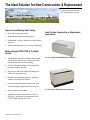
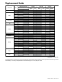
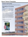
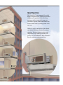
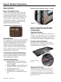
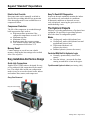
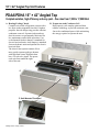
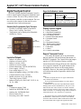
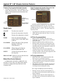
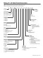
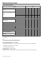
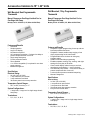
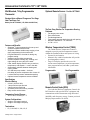
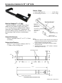
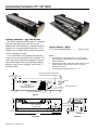
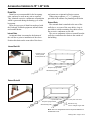
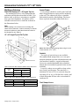
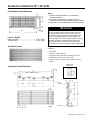
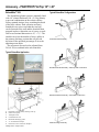
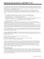
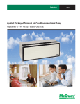
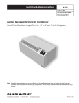
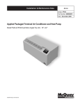
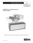
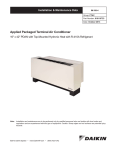
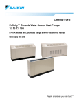
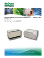
Applied Packaged Terminal Air Conditioner and
Heat Pumps
Catalog 1300-2
16" × 42" Angled Top – Model PDAA/PDHA
16" × 42" Flat Top – Model PDAF/PDHF
Model PDAF/PDHF
Model PDAA/PDHA
Engineered for flexibility and performance™
Table of Contents
Introduction
The Ideal Solution For New Construction and
Replacement...................................................... 4
Replacement Guide................................................. 5
Unit Features
Beyond "Standard" Expectations...................6-9
16" × 42" Angled Top Unit........................10-11
16" × 42" Flat Top Unit..............................12-13
Applied Unit Features
Unit Components............................................ 14
Touchpad Controls.....................................15-16
Premium, Programmable Touchpad with
Auto Changeover............................................ 16
Model Nomenclature............................................ 17
Model Quick Selection Guide............................... 18
ARI Performance Data.......................................... 19
Accessories Common to 16" × 42" Units.....26-33
Thermostat Quick Selection Guide................. 26
Thermostats................................................27-28
Electrical 3" or 4" Subbase............................. 29
Hydronic Subbase 8"...................................... 30
Drain Kits........................................................ 31
Wall Sleeve Extension.................................... 32
Louver Frame.................................................. 32
Louvers........................................................... 33
Accessory – PDAF/PDHF Flat Top 16" × 42"
ExtendAire Kit................................................ 34
Wiring Diagrams - Digital Control
Premium Programmable Digital Control....... 35
Stnd. (Non-Programmable) Digital Control... 36
Digital Control Board with Standby Power... 37
Digital Control Board without Standby Power.... 38
Engineering Guide Specifications.................39-42
Dimensional Data
16" × 42" Angled Top Unit............................. 20
Typical Installation Types 16" × 42"..........21-24
16" × 42" Flat Top Unit................................... 25
“McQuay” and “Incremental” are registered trademarks of
McQuay International.
©2009 McQuay International
Bulletin illustrations cover the general appearance of McQuay products
McQuay Applied Packaged Terminal Air Conditioners and Heat Pumps are certified in
accordance with the Packaged Terminal Air-Conditioners certification program which is based
on ARI Standard 310 and in accordance with the Packaged Terminal Heat Pump certification
program, which is based on ARI standard 380.
Catalog 1300-2 / Page of 42
The Ideal Solution for New Construction & Replacement
450,000 square foot manufacturing
plant, located in Auburn, New York
Superior Zoned Heating And Cooling:
•
•
•
Hotel and motel guest rooms
•
Offices and other spaces in a variety of buildings
Hospitals and assisted living facilities
Ideal For New Construction or Replacement
Applications
Apartments, college dormitories and military
barracks
McQuay Applied PTAC/PTHP Is The Right
Choice!
•
The broadest selection of features and customizable options allows you to choose the ideal
unit for each space in your building.
•
R-410A refrigerant with no ozone depletion
potential or phase-out date.
•
High energy efficiency and COP ratings provide lower operating costs.
•
Reliable cooling/heating and low operating
sound levels maximize comfort.
•
Proven institutional grade construction withstands demanding applications for long life.
•
Easy to install and maintain.
•
Engineered and produced in the U.S.A. by
McQuay – the pioneer of Incremental® and
PTAC/PTHP systems since 1955.
Catalog 1300-2 / Page of 42
16" × 42" Angled Top PDAA/PDHA (with accessories)
16" × 42" Flat Top PDAF/PDHF (with accessories)
Replacement Guide
Wall Opening Dimension Discharge Return Air Heat Type
Manufacturer
Model
161/4" x 421/4"
Angled Flat
Bottom Front
Electric Hydronic
AC
HP
PTC
•
•
•
•
•
Amana
PTH
•
•
•
•
52PE
•
•
•
•
56PC
•
•
•
•
•
•
•
Carrier56PQ
52SC
•
•
•
52SE
•
•
•
•
52SQ
•
•
•
•
PTA
•
•
•
•
Climate Master
PTP
•
•
•
•
PTH
•
•
•
•
PC
•
•
•
•
CNI
PH
•
•
•
•
PDE
•
•
•
•
PDH
•
•
•
•
PE
•
•
•
•
PH
•
•
•
•
Friedrich
TE
•
•
•
•
TH
•
•
•
•
TW
•
•
•
•
GE
AZ
•
•
•
•
•
Ice Air
RSCT
•
•
•
•
ED
•
•
•
•
•
Island Aire
NE
•
•
•
•
PDE
•
•
•
•
•
•
PDH
•
•
•
•
•
PSE
•
•
•
•
•
PSH
•
•
•
•
McQuay
MQE
•
•
•
•
•
•
MQR
•
•
•
•
MQS
•
•
•
•
•
•
NR
•
•
•
•
PTAC
•
•
•
•
PTHP
•
•
•
•
N
•
•
•
•
NE
•
•
•
•
Singer
NH
•
•
•
•
NR
•
•
•
•
PTE
•
•
•
•
•
Trane
PTH
•
•
•
•
= Not Applicable
Not finding what you are looking for? Consult your McQuay representative for information on other replacement PTAC/PTHP products
from McQuay. To locate your representative, visit www.mcquay.com or call (800) 432-1342.
Catalog 1300-2 / Page of 42
Beyond “Standard” Expectations
Customize To Suit Your Needs
Select from a wide variety of features, factory-supplied options and accessories to
build the ideal unit for your application and help reduce labor and installation costs.
Energy Efficient For Low Operating
Costs
Applied PTAC/PTHP units are ARI certified units
built with quality components and exceed industry
standards for energy efficiency. This helps lower
your utility costs by keeping energy consumption
down and may allow you to qualify for electrical
power company rebates.
Built-in energy management logic comes standard
with the unit’s digital controls. Features such as
the Sleep Function allow users to decrease the set
temperature at night and during unoccupied periods
to conserve energy. For heat pump applications,
electric heat comes on only when the outdoor coil
temperature is below 28°F, maximizing the amount
of time the unit operates in the more efficient heat
pump mode.
*Consult your utility provider for rebate
opportunities.
Non-Ozone Depleting
R-410A Refrigerant
Quiet Operation
The GentleFlo™ cross-tangential fan wheel
design of Applied PTAC/PTHP units provides
whisper quiet operation while delivering
maximum airflow required for proper air
circulation. Separate indoor and outdoor fan
motors further reduce operating sound levels
and costs.
The heavy gauge construction of the chassis
and cabinet minimizes vibration for quieter
operation. Vibration isolators on the rotary
compressor keep it running smoothly and
quietly. The unit bulkhead is fully insulated to
decrease outdoor sound transmission.
Beyond “Standard” Expectations
Room Comfort
Manual Fresh Air Damper Control - Left End
Easy To Use Digital Controls
The unit control pad offers digital readout and
is easy to use when selecting fan speed, mode
of operation and temperature setting. A precise
digital temperature display provides guests with
an exact comfort setting, thereby eliminating
uncomfortable temperature swings and costly
overheating/overcooling associated with nondigital electromechanical controls.
Manual outdoor
damper
Standard Digital Touchpad Control
Built-In Reliability And Durable
Construction
High-Grade Cabinetry
Dehumidification:
The cool/dry mode automatically controls humidity
by extending the cool cycle without sacrificing
comfort for dehumidification. This mode comes
standard with all units. The desired cooling
mode (cool/dry for added dehumidification or
regular cool) can be selected and locked by the
owner or facility manager to meet comfort and
dehumidification requirements.
Applied PTAC/PTHP cabinets are constructed of
18-gauge steel with baked on powder coat paint for
maximum durability and aesthetic appeal. Grilles
are constructed of impact resistant polycarbonate.
Positive Condensate Removal
Our unique three level sloped basepan design
provides positive condensate removal to prevent
condensate build-up or overflow.
Constant Room Temperature Monitoring
Units are designed to automatically sample the
room temperature and adjust operation to meet
desired temperature set points.
Indoor Air Quality Options
●
●
●
Damper control – Outdoor fresh air is brought in through a manual or automatic (optional) damper.
Fresh Air Damper – Can be added to your auto damper. This will deliver 90 cfm of outdoor air into the space.
Cleanable filters – Easy to remove, cleanable filters come standard with each unit.
Catalog 1300-1 / Page of 42
Positive condensate
removal
Room Freeze Protection
When the unit senses temperatures of 40°F or
lower in an unoccupied room, the heat mode is
automatically initiated to prevent freezing. The
outdoor fan and compressor are stopped to help
prevent coil freeze.
Beyond “Standard” Expectations
Electric Heat Override
Easy To Read LED Diagnostics
Compressor Protection
The Hydronic Experts
Heat pump units can be manually switched to
electric heat, providing added freeze protection
if the heat pump mode is not available due to a
compressor failure.
The life of the compressor is extended through
built in protection logic such as:
● High temperature protection if the compressor temperature exceeds 154°F
● Minimum run time
● Minimum off time
● Random restart after a power outage
● Low ambient lockout when the outdoor air temperature falls below 25°F
Memory Recall
Control settings are saved in a non-volatile
memory, allowing the last settings to be recalled
after a loss of power.
Easy Installation And Service Design
Quick Link Connections
Applied PTAC/PTHP units are designed for easy
access with quick link connections to the control
box. The simple slide in/slide out configuration
makes it easy to access the electric heater, indoor
and outdoor fans, motors, and compressor.
Sensors in the unit continually monitor the indoor
coil, outdoor coil, and outdoor air conditions.
If abnormal conditions are detected, an error
code is displayed, removing the guess work in
troubleshooting a unit.
McQuay is a leading manufacturer of hydronic heat
equipment. We specialize in providing hydronic
heat with a host of configurable options.
Modes
●
●
●
●
Cooling only mode with hydronic heat
Cooling only mode with hydronic heat and
supplemental electric heat.
Top mounted hydronic coil
(steam or hot water)
Subbase hydronic (steam or hot water)
Controls-With Built In Hydronic Logic
●
●
Normally open/normally closed valve control
Heat fan lockout – prevent the fan from coming on until there is heat in the pipes.
Top-Mounted Hydronic Heat (see Catalog 1355)
Easy Fan Removal
Easy fan motor removal
Catalog 1300-1 / Page of 42
16" × 42" Angled Top Unit Features
PDAA/PDHA 16" × 42" Angled Top
Complete solution, high efficiency and very quiet – five sizes from 7,000 to 17,000 Btuh
A. Heating/Cooling Chassis
Complete air-cooled refrigeration system with a
low noise indoor tangential fan wheel. Outdoor
propeller fan with slinger ring provides efficient
condensate removal. Separate indoor and outdoor fan motors are permanently lubricated for
low maintenance and reliable operation. Concealed manual fresh air damper is standard for
electric heat/cool units. Auto damper is standard
for most hydronic units and optional for electric
heat/cool units.
The electric heat system consists of low
mass, quick response grid type heaters
with high limit cutout. Hydronic heat
has a 24-volt valve signal. The power
cord exits from under the right
side of the unit.
A
B. Evaporator And Condenser Coil
High capacity coils employ optimized heat
transfer technology to provide maximum comfort to the conditioned space while minimizing
the energy required to operate the unit.
D
B
C
E
F. Unit Mounted Touchpad
Catalog 1300-2 / Page 10 of 42
16" × 42" Angled Top Unit Features
C. Basic Wall Sleeve (BWS)
16" high × 42" wide × 13.75" deep and constructed from galvanized 18-gauge steel that is
primed and pre-painted with an antique ivory
finish. It is insulated and arrives in a removable
protective plastic film.
Custom Wall Sleeve (CWS) (optional) is
constructed of G-60 galvanized, phosphatized
18-gauge steel with a baked-on epoxy based
powder coat paint finish to provide maximum
corrosion protection. The top interior and side
interior surfaces are insulated. Can be customized for extended depths, recessed louvers and
wall flanges.
D. Louver (Accessory)
Flush stamped or architectural style.
Constructed of anodized aluminum.
E. Room Cabinet
Angled top discharge with one piece stamped
discharge grilles. Cabinet is constructed of 18gauge steel with baked on powder coat paint.
The entire room cabinet is an attractive antique
ivory color. The control access door is on the
right side of the cabinet.
F. Digital Control Module
The digital control module is used to control the
cooling and heat mode(s) of the unit and to provide diagnostic information for troubleshooting.
The standard digital control module is operated
using a unit mounted touchpad or a 24-volt wall
mounted thermostat.
Catalog 1300-2 / Page 11 of 42
16" × 42" Flat Top Unit Features
16" × 42" Flat Top Unit
Complete solution, high efficiency and very quiet – five sizes from 7,000 to 17,000 btuh
A. Heating/Cooling Chassis
Complete air cooled refrigeration system with a
low noise tangential fan, outdoor propeller fan
with slinger ring provides efficient condensate
removal. Fan motors and concealed manual
fresh air damper (auto damper for hydronic).
The heating system with electric heat consists
of low mass, quick response grid type electric
heaters with high limit cutout. Hydronic heat
has a 24-volt valve signal. Power cord exits
from under the right side.
C. Digital Control Module
The Control Module is used to control the
PDAF or PDHF unit that includes both an
integral air conditioner and a source or two of
heat. The digital control is operated with a unit
mounted touchpad or 24-volt wall mounted
thermostat.
C. Unit Mounted Touchpad
F
A
B
L
D. ExtendAire™ (Option)
The ExtendAire accessory is a cabinet extension kit designed to provide balanced heating
and cooling in two rooms using a single PDAF/
PDHF unit.
E
D
B. Room Cabinet/Front Cover – Flat top discharge grille with a single, stamped steel grille.
The front panel raises and can be completely
removed for service and chassis access. The
cabinet is a wrap around design and completely
encloses the chassis. The entire room cabinet is
an attractive antique ivory color.
Catalog 1300 -1/ Page 12 of 42
B
Applied 16" × 42" Chassis Common Features
E. Hydronic Subbase Heat Section (Option) –
2-row, finned/tube coil furnished for either hot
water or steam and mounted in an 8" subbase.
5/8" O.D. copper pipe connections supplied.
Louvered subbase front panel with quick opening latches is hinged for easy access to piping,
valves and 1/2" permanent filter. Optional fused
disconnect available when required. Subbase
has side channels for up to 13¾" adjustment.
Includes receptacle.
H. Tangential Indoor Fan
The indoor fan evenly circulates air across the
evaporator coil and into the occupied space.
This fan is constructed of metal and the motor
incorporates permanently lubricated bearings to
help provide uninterrupted service.
Quiet Running
F. Louver (Accessory)
Flush stamped or architectural style, anodized
aluminum.
G. Evaporator And Condenser Coil
High capacity coils employ the latest in heat
transfer technology to provide maximum
comfort to the conditioned space while minimizing the energy required to operate the unit.
I.
Fan Motors
High efficiency, quiet PSC fan motors. All motors are permanently lubricated for extended life. The outdoor fan motor is totally enclosed to help prevent damage from driving rain or excess condensate accumulation in humid climates.
Indoor Fan Motor
Outdoor Fan Motor
H
Typical Library
Applied PTAC - Size 012
Fan Only - Low Speed
Applied PTAC - Size 012
Cooling Only - Low Speed
Conversational Speech
Sound Comparison
Exceptionally Quiet Operation
G
J
L
I
K
Catalog 1300-1 / Page 13 of 42
Applied 16" × 42" Chassis Common Features
J.
J.Compressor
The reliable, high efficiency rotary compressor
is hermetically sealed and designed for continuous operation. The compressor is isolated to
minimize vibration and sound transmission for
quiet operation.
K. High Capacity Heat Transfer Surfaces
The finned/tube coils incorporate state-of-
the-art technology. The unique design of these coils provides high efficiency and low air pressure drops, in addition to allowing for easy cleaning during scheduled maintenance.
K. Outdoor Coil
K. Indoor Coil
L.
Filtration
Room side return air is filtered through this permanent, washable polypropylene mesh filter. It is UL listed class II, 38% average arrestance efficiency (ASHRAE test), with low resistance to airflow (0.02 w.g. at 300 cfm), and high dust holding capacity (55 grams).
Catalog 1300-1 / Page 14 of 42
L. Permanent, Washable Polypropylene Mesh Filter
(Shown in front return configuration)
Applied 16" × 42" Chassis Common Features
Digital Touchpad Control
Keys And Indicators Labels
The PDAC/PDHP Standard Touchpad Control is
used to control both an integral air conditioner and
a source of heat. The user will by default control
the electronic controller via the touchpad. The user
can select with a jumper for the unit to receive
commands from a remote thermostat.
Standard (Non-Programmable) Dgital Touchpad
• Provides 5-selectable modes of operation:
Sleep, Cool, Cool/Dry, Fan, Heat
• Temperature can be displayed in Fahrenheit
(default) or Celsius
LED
2-Digit Display
9- LED
Indicators
7- Push Buttons
7 Push Buttons
9 LED Indicators
LED 2 Digit Displays
ON/OFF, FAN SPEED, MODE
FAN MODE, SLEEP
Temp buttons:
for
Temp UP and
for Temp DOWN
SLEEP, COOL, COOL/DRY, FAN, HEAT, HIGH, LOW, CYCLE, CONT.
No Label
Display Function Legend
Tr = Room Temperature
hI = High Room Temperature
Lo = Low Room Temperature
LA= Low Ambient Lockout
rT = Remote Thermostat Control
tP = Touchpad Control
t = Time
Ts = Temperature Setpoint
Rf = Room Freeze Condition
CF= Coil Freeze Protection
F = Fahrenheit
C = Celsius
LC= Control Lockout Mode
Remote Thermostat Control
Inputs And Outputs
•
•
•
•
•
•
•
•
•
•
•
•
Indoor coil sensor, (ICS)
Outdoor coil sensor, (OCS)
Indoor air sensor, (IAS)
Outdoor air sensor, (OAS)
Remote thermostat, T’STAT (RCBYWG)
Power supply: (24VAC)
Line voltage input, (L1, L2)
Indoor fan standby voltage, (L1STB L2STB)
Control selection: (LUI, T’STAT
Model selection: (AC/E, HP, HP/E)
Time delay bypass, (TEST)
Indoor off fan cycle: (FAN, OFF CYCLE–10,
20, 30, 1 HR)
Outputs
•
•
•
•
•
Compressor output, COM
Indoor fan, BLOWER LO, HI
Outdoor fan, OUTDOOR FAN
Electric heater, ELE
Reversing valve, REV VALVE
The remote thermostat can be any thermostat
that can interface with an electronic thermostat via
RCBWYG terminals. The Control Selection jumper
must be in T’STAT position. During a call the
remote thermostat will pass R back to the controller
on a respective terminal. The push buttons on the
touchpad become inactive in the remote thermostat mode. However, the control pad LED display
will indicate the mode of operation, and the room
temperature.
Note:
In terms of outputs, there are two types of thermostats:
relay contacts and solid state.
If you open the thermostat and don’t see relays then it
must be solid state.
Manufacturers of solid state output thermostats include
loading resistors on their installation kits. They are of 560
Ohm and 3W value. These resistors are meant to load thermostat solid state outputs in order for the output voltage to be
either 0 or 24VAC, i.e. no floating voltage. These resistors are
connected from W, Y, G to common (C), respectively.
You can wire any type of 24Vac thermostat straight into
the REMOTE T’STAT connector of PTAC control boards,
667997101 and 667997201 (Basic and Premium models) and
the control boards will recognize the signals from them.
Catalog 1300-1 / Page 15 of 42
Applied 16" × 42" Chassis Common Features
Premium (7-Day Programmable) Digital Touchpad
• Provides all the features of the Standard Controller, plus master/slave, infra-red control, auto
damper, wall mounted remote thermostat, heat
fan lockout
Digital Touchpad with Automatic Changeover from
Cooling to Heating & Heating to Cooling
LED with
Program Setting
Display
9-LED
Indicators
8- Push Button
Display Inputs
Display Inputs:
ON/OFF
Increase the temperature set point
MODE Select one from the following modes: COOL, COOL/DRY, FAN,
or HEAT
Turn the unit on and off
Decrease the temperature set point
FAN MODE Change the mode of fan operation
between CYCLE and
CONTINUOUS
FAN SPEED Change the speed of the fan between HIGH and LOW
SLEEP
AUTO
Available with the Programmable LUI (668003801)
and Premium Board (667997301) only. The AutoChangeover board has a new control set with a touchpad label that shows, “AUTO”. The Auto Changeover
control provides:
•
•
Auto changeover from heat to cool and vice versa
LED's from top down that read: Sleep, Cool, Auto,
Fan, and Heat
AUTO Non-Programmable Mode:
•
•
•
•
•
Activate the sleep mode and set the sleep time
Display shows both HEAT and COOL icons
Temperature set point displays between the HEAT
and COOL icons
Setpoint is adjusted with Up and Down arrows
Heating initiates when the room temperature falls
one degree below the thermostat setpoint. Heating
terminates when the room temperature reaches two
degrees above the setpoint
Cooling initiates when the room temperature
reaches one degree above the thermostat setpoint.
Cooling terminates when the room temperature falls
two degrees below the setpoint
PROG ON/OFF Button to activate and deactivate the program mode
AUTO Programmable Mode:
Master-Slave Control (Optional)
•
A single master unit can be configured to control up to 32 slave units. The master unit controls
on/off, fan, settings and sleep functions for the
secondary units.
•
•
HEAT and COOL icons alternatively flash with
their respective programmed setpoints
The system engages cooling and heating automatically to maintain respective setpoints according to
system model selection
The 2-degree gap between setpoints represents the
deadband and is necessary to prevent unecessary
switching between heating and cooling
The 2 degree deadband provides the following:
Catalog 1300-1 / Page 16 of 42
• Heating activates when the room temperature is
one degree below the thermostat setpoint plus the 2
degree deadband.
• Cooling activates when the room temperature is
one degree above the thermostat setpoint plus the 2
degree deadband
McQuay 16" × 42" Model Product Nomenclature
Note: For Illustration purposes only. Not all options available with all models.
Please consult a McQuay Sales Representative for specific availability.
P DAA 2 009 E M A
H
A
B
D
M A A E
Unit Type
Warranty
P = PTAC
A = Standard
E = Extended
X =Special
Product Identifier
DAA= Air Conditioner – Angled top
DHA = Heat Pump – Angled top
DAF = Air Conditioner – Flat top
DHF= Heat Pump – Flat top
SKU
A = Stock
B = Build to Order
Design Series
1 = A Design 1
2 = B Design 2
3 = C Design 3
4 = D Design 4
5 = E Design 5
Upgrade Packages
S = Seacoast
Y = None
Unit Size
007 = 7,000
009 = 9,000
012 = 12,000
015 = 15,000
017 = 17,000 (Cooling Only)
Power Connection
L = Long Cord – 72" (Standard)
S - Short Cord – 30" (Optional)
30" Cord, Standard w/Hydronic
Subbase
Y = None
Voltage
A = 115-60-1
E = 208/230-60-1
J = 265/277-60-1
P = 208/230-60-1 w/stndy 115-60-1
R = 265-60-1 w/stndy 115-60-1
T = 208/208-60-1
Room Interface
Cabinet Type
B = Angled Top (16" × 42")
C = Flat Top (16" × 42")
Brand Name
M = McQuay
Controls
Control Board Type
B = Basic Control
P = Premium Controls
(Req'd for Hydronic Heat)
User Interface Type
P = Programmable (Unit Mtd. Touchpad)
A = Programmable with Auto Changeover
(Unit Mtd. Touchpad)
N = Non-Programmable
(Unit Mtd. Touchpad)
Y = None (Wall Stat with Blank-off Plate)
Refrigerant
A = R-410A
Heating Type
E = Electric Heat
H = Hydronic
A = Hydronic w/Intermediate Electric
Y = None (PDHP only)
Electric Heat
A = 2.5 Kw
B = 3.5 Kw
C = 5.0 Kw
Y = None
Hydronic Heat Type
S = Steam Top Mount (Normally Closed)
T = Steam Subbase (Normally Closed)
H = Hot Water Top Mount (Normally Open)
J = Hot Water Subbase (Normally Open)
Y = None
Damper Type
Damper Control
A = Automatic (Required for Hydronic Heating Subbase)
A = Fresh Air Boost Fan
M = Manual
Y = No Damper
Catalog 1300-2 / Page 17 of 42
Model Quick Selection Guide
Chassis Customization Options
Description Unit Size
Unit Type - PDAC/PDHP
007
009
012
16 x 42 Top Mount Hydronic
Cabinet Type
16 x 42 Angled Top
16 x 42 Flat Top
115-60-1
208/230-60-1
265/277-60-1
Voltage
208/230-60-1 w/ standby 115-60-1
265/277-60-1 w/ standby 115-60-1
208/230-60-1 w/ standby (all sizes)
Cooling Capacity BTUH
•
•
•
•
•
•
•
•
•
•
•
•
•
•
•
•
•
•
7,4009,100
•
•
•
n/a
•
•
n/a
n/a
•
12,800
015
017
•
•
•
•
•
•
n/a
•
•
n/a
n/a
•
n/a
n/a
n/a
n/a
•
•
14,400
16,800
Heating Options
•
•
•
•
5.0
n/a
n/a
Hydronic - Hot Water or Steam
•
•
•
•
•
•
•
•
•
•
•
•
•
2.5
Electric Heater (kW)
3.5
Hydronic with Intermediate Electric (PDAA and PDAF units)
Heat Pump
Heat Pump with Supplemental Electric Heat
Air Flow CFM - High/Low Speed in Heating
380/340
Outside Air Damper - Vent - CFM-High/Low Speed 50/40
Damper
Auto Damper Control (Standard for most Hydronic Heat)
Manual Damper Control (Not available for most Hydronic Heat)
Indoor Air Quality (IAQ) Boost Fan
No Damper
w/ Auto Damper
Unit control
Unit Mounted Non-programmable
Unit Mounted Programmable
Seacoast Coating Package •
•
•
•
•
•
•
•
•
•
•
•
•
•
•
•
•
•
•
•
•
•
•
•
•
•
•
•
•
•
•
•
•
•
•
•
•
•
•
•
•
•
•
•
•
n/a = not applicable
Notes:
For illustration purposes only. Not all options available with all models.
Consult a McQuay Sales Representative for details and availability.
Other Customization Options – 16¨ x 42¨ Units
• Custom Sleeve - Extended depths, brick stops, or support legs can be added for panel wall or curtain wall applicatons.
• Custom Cabinet - Extended depths, colors, kickplates
• Factory-installed valves and hydronic coils
Model PDAF/PDHF – Flat Top 16¨ x 42¨
• ExtendAire - a cabinet extension kit designed to provide balanced heating and cooling in two rooms using a single unit.
Catalog 1300-2 / Page 18 of 42
•
•
•
•
•
n/a
n/a
550/380
70/50
•
•
•
•
•
•
•
ARI Performance Data(6)
UNIT SIZE
007 009
012 Total Btuh(1)
7,400
7,400
7,4009,1009,1009,100
12,800
015
12,800
14,400
017
14,400
16,800
11,700
Sensible Btuh(1)
6,500
6,500
6,500
7,500
7,500
7,5009,0009,0009,6009,600
Cooling
EER
10.9
10.9
10.9
10.7
10.7
10.79.89.89.49.49.3
Volts
115
208/230
265
115
208/230
265
208/230
Full Load Amps(6)
7.43
4.07
3.349.335.45
4.04
7.15
6.098.21
6.69
10.03
Watts(1)
679
679
679850 850850
1,306
1,306
1,532
1,532
1,806
Volts
208/230
208/230
265
208/230
265
208/230
kW
2.2/2.7
2.5 kW
Amps
kW
3.1/3.8
3500
3.1/3.8
3500
3.1/3.8
3500
3.1/3.8
3500
3.1/3.8
Amps
15.2/16.8
13.7
15.2/16.8
13.7
15.2/16.8
13.7
15.2/16.8
13.7
15.2/16.8
Electric Heat(3)
3.5 kW
5.0 kW
265
10.7/11.9
208/230
265
265
208/230
265
2.2/2.7
2.2/2.7
2.2/2.7
2.2/2.7
10.7/11.9
10.7/11.9
10.7/11.9
10.7/11.9
kW
Amps
Valve & Fan
0.74
0.41
0.32
0.74
0.41
0.32
Motor Amps
Hydronic Heat(4)
Hot Water (Btuh) Hi/Lo 18,400/15,600 18,400/15,600
Steam (Btuh) Hi/Lo
22,400/22,300 22,400/22,300
Heat Pump Model
3.9/4.85,000
19.0/21.0
19.3
0.41
0.32
3.9/4.85,000
19.0/21.0
0.41
19.0/21.0
0.32
0.47
18,400/15,600
18,400/15,600
23,200/16,400
22,400/22,300
22,400/22,300
27,900/23,300
Qt, Btuh(2)
7,400
7,400
7,4009,2009,2009,200
Qs, Btuh(2)
6,500
6,500
6,500
7,500
12,700
12,700
14,200
14,200
Cooling
EER
10.9
10.9
10.9
Volts
115
208/230
265
Full Load Amps
7.43
4.07
Watts(1)
679
679
679893893893
1,296
1,296
1,511
1,511
Btuh(2)
6,800
6,800
6,8008,5008,5008,500
12,400
12,400
14,000
14,000
Reverse COP
3.2
3.2
3.2
3.3
3.3
3.3
3.0
3.0
2.9
2.9
Cycle
Volts
115
208/230
265
115
208/230
265
208/230
265
208/230
265
Heat
7,500
7,5009,0009,0009,5009,500
10.3
10.3
10.39.89.89.49.4
115
208/230
3.349.335.45
3.9/4.8
19.3
208/230
265
208/230
4.04
7.15
265
208/230
6.098.21
265
6.69
Full Load Amps
7.43
4.07
3.349.335.45
4.04
7.15
6.098.21
6.69
Electric Heater
Watts(2)
623
623
623
755
755
1,211
1,211
1,415
1,415
Voltage
240V
240V
265V
240V
265V
240V
265V
Minimum
Circuit
Ampacity
2.5 Kw
15.51
15.51
15.51
3.5 Kw
21.92
21.92
21.92
17.07
21.92
17.07
21.92
27.38
24.1
27.38
24.1
27.38
7.97
12.07
Time Delay Fuses
or Type HACR
Circuit Breaker
2.5 Kw
15
15
15
15
15
3.5 Kw
20
20
20
15
20
15
20
5.0 Kw
25
20
25
20
25
Hydronic Heat
15
15
15
15
15
755
265V
17.07
17.07
5.0 Kw
Hydronic Heat
8.69
4.77
15
15
3.89
11.06
15
15
15
6.49
15
4.778.48
15
15
15.51
7.229.8
240V
15.51
2.5 Kw
6-15R
6-15R
6-15R
6-15R
6-15R
3.5 Kw
6-20R
6-20R
6-20R
7-20R
6-20R
7-20R
6-20R
5.0 Kw
6-30R
7-30R
6-30R
7-30R
6-30R
Hydronic Heat
6-15R
7-20R
6-15R
7-20R
6-15R
NEMA
Receptacle
Type Required
5-15R
6-15R
7-20R
7-20R5-15R
6-15R
7-20R
7-20R
High
Low
High
Low
High
Low
High
Low
High
Low
Airflow
Cool
360
330
360
330
360
330
360
330540
360
CFM
Heat
380
340
380
340
380
340
380
340550
380
Vent(5)
50
4050
4050
40
50
40
(1) Based on ASHRAE and ARI test conditions of 95°F DB/75°F WB outside, 80°F DB/67°F WB inside.
(2) Based on ASHRAE and ARI test conditions of 47°F DB outside, 70°F DB inside.
(3) Electric Resistance Heat Watts x 3.41 = Btuh. Electric Heating Watts and Amps include Indoor Fan Motor.
(4) Water – Based on ASHRAE and ARI test conditions of 200°F EWT, 180°F LWT, 70°F EAT with a 1.8 gpm flow rate.
(5) 90 cfm with Power Vent Option.
(6) Cooling Full Load Amps includes Compressor, IDF and ODF FLA's.
Unit Weights - (lbs.)
Model
= Not Applicable
16" x 42" Wall Sleeve
007
009
012
015
017
16" x 42" (Angled) PDAA (Chassis)
129.5
137
137.9
145.6
150.6
16" x 42" (Angled) PDAA (Packaged)
144.5
152.0
152.9
160.6
165.6
16" x 42" (Angled) PDHA (Chassis)
129.5
137.0
137.9
145.6
131
138.5
139.9
147.1
*16" x 42" (Flat) PDAF
129.5
137
137.9
145.6
150.6
*16" x 42" (Flat) PDAF (Packaged)
144.5
152
152.9
160.6
165.6
16" x 42" (Angled) PDHA (Packaged)
7050
*16" x 42" (Flat) PDHF
131
138.5
139.4
147.1
*16" x 42" (Flat) PDHF (Packaged)
146
153.5
154.4
162.1
* Includes Chassis and Cabinet Assembly (Wall Sleeve Ships Separate)
(Packaged)...................................................28 lbs. (13 kg)
Louvers
Flush-stamped..................................................6 lbs. (3 kg)
Architectural.....................................................8 lbs. (3 kg)
Subbase
3" (76mm) High Electrical..............................10 lbs. (5 kg).
4" (102mm) High Electrical..........................12 lbs. (5.4 kg)
8" (203mm) High Hydronic.............................20 lbs. (9 kg)
Catalog 1300-1 / Page 19 of 42
Dimensional Data – 16" × 42" Angled Top Unit
Cabinet & Wall Sleeve
3/8" (Stamped) Louver
11/8" (Architectural)
42" (1067mm)
133/4"
(349mm)
81/4"
(210mm)
43" (1092mm)
1" (25mm)
22o
16"
(406mm)
17"
(432mm)
See Note 1
411/2" (1054mm)
Note: Unit pictured with subbase installed. Subbase is optional on 208V 230V
units. Subbase is standard on all 265V and units with hydronic heat. See page
29 for subbase dimensions. Sides are adjustable.
Chassis
Catalog 1300-2 / Page 20 of 42
81/4"
(210mm)
See Note
22"
(559mm)
Typical Installation Types
Wall Opening Requirements – 16" × 42"
When roughing in the opening for the wall
sleeve, sufficient clearance from the walls and floor
is required. The wall sleeve should be positioned a
minimum of 5/8" from the finished side wall to accommodate the room cabinet. A minimum distance
of 3" above the finished floor is required for return
air.
The rough opening should measure 161/4" high ×
421/4" wide. When using a louver frame, the opening must measure 165/8" × 425/8". Louver frames
should be used for panel wall and thin wall applications to provide positive anchoring to the wall.
When an electrical subbase is used, the opening
must start 3" to 4" above the finished floor (including carpeting) to match the height of the subbase
selected. The subbase is available in 3" or 4"
heights and has adjustable leveling legs that provide up to an additional 1" height.
Masonry Wall (Thick)
Room Side
Wall Sleeve Extension
Splitters
Lintels (by others)
16" x 42"
Wall Sleeve
Frame And Brick
16" x 42"
Wall Sleeve
Lintel
(by others)
Wall Construction Examples
Panel Wall (Thin)
161/4" High
Steel Studs
421/4" Wide Wall
Sleeve Rough Opening
Concrete
Pillars
161/4" x 421/4"
Floor
Wall Sleeve
Rough Opening or
165/8" x 425/8" When using a
Louver Frame (see page 34 for details)
Catalog 1300-2 / Page 21 of 42
Typical Installation Types
Frame And Brick Construction Examples
Frame And Brick With Electrical Subbase
Frame And Brick With Hydronic Subbase
Steel Lintel
(by others)
Steel Lintel
(by others)
Outside
Louver
Outdoor Louver
43/8"
(111mm)
133/4"
(349mm)
Mounting
Holes
(by installer)
8 /4"
(209mm)
17"
(432mm)
16"
(406mm)
Room
Cabinet
Wall Sleeve
Subbase
Caulk Perimeter
both Indoor and
Outdoor Before
Installing Louver
133/4"
(349mm)
1
See Note
Leveling
Finished Floor
Leg
or Top
Power Supply Connect
of Carpet
(Alternate Entry)
Note: Standard subbase is available in 3" or 4" (76 mm) or (102 mm) height. Leveling legs provide adjustment
of 1" (25 mm).
Frame And Brick With Cord Connection
Steel Lintel
(by others)
Mounting
Screws
by Installer
133/4"
(349mm)
81/4"
(209mm)
17"
(432mm)
16"
(406mm)
Outdoor
Louver
Wall Sleeve
Caulk Perimeter
Room
Cabinet
3" Min. (76mm)
Wall
Receptacle
(by others)
Catalog 1300-2 / Page 22 of 42
Finished Floor
or Carpet
Mounting
Screws
by Installer
Caulk
Perimeter
both Indoors
and
Outdoors
Before Installing
Louver
81/4"
(209mm)
17"
(432mm)
16"
(406mm)
Wall Sleeve
Room
Cabinet
Hydronic
Heating
Coil
81/4"
(209mm)
Subbase Side
Channel
Alternate
Electrical
Connections
Finished Floor
or Carpet
Hydronic Subbase
Leveling Leg
Typical Installation Types
Panel Wall Construction Examples
Panel Wall With Standard Electrical Subbase
Panel Wall With Hydronic Subbase
Louver Frame
(see page 32 for details)
Louver Frame
(see page 32 for details)
Outside
Louver
81/4"
(209mm)
Wall Sleeve
17"
(432mm)
17"
Room
(432mm) Cabinet
133/4"
(349mm)
81/4"
(209mm)
16"
(406mm)
Room
Cabinet
Hydronic
Heating
Coil
Electrical
Subbase
Gasket
& Caulk
Perimeter
See Note
81/4"
(209mm)
Outside
Louver
133/4"
(349mm)
16"
(406mm)
Wall Sleeve
Caulk
Perimeter
both Indoors
& Outdoors
Subbase
Side
Channel
Floor
Power Supply Connect
(Alternate Entry)
Subbase Side Channel
Note: Standard subbase is available in 3" or 4" (76 mm) or (102mm) height. Leveling legs provide adjustment
of 1" (25 mm).
17"
(432mm)
141/8"9 1/2"
147/8"
103/8"
131/8"
14"
16"
(406mm)
Wall Sleeve
Room
Cabinet
3"Min. (76mm)
Caulk
Perimeter
both Indoors
& Outdoors
Floor
Outside
Louver
Stamped 3/8"
Architectural 11/8"
Hydronic
Subbase
133/4"
(349mm)
81/4"
(209mm)
Receptacle
(by others)
Table 1. Maximum Wall Thickness without Sleeve Extensions
Maximum Wall Thickness
Louver
No
Standard
Type
Subbase
Subbase
Panel Wall With Cord Connection
Louver Frame
(see page 32 for details)
Power Supply Connect
(Alternate Entry)
Leveling Legs with 1” Adjustment
Conduit
Minimum
2 Supports
(field supplied)
Catalog 1300-2 / Page 23 of 42
Typical Installation Types
Thick Wall Construction Examples
Thick Wall With Electrical Subbase
Thick Wall With Hydronic Subbase
See Table 1,
page 23
See Table 1,
page 23
Steel Lintel
(by others)
Caulk
Perimeter
Mounting
Screws
(by installer)
Outside
Louver
43/8" Min.
(111mm)
See
Note
2
133/4"
(349mm)
16"
(406mm)
Wall
Sleeve
Extension
Electrical
Subbase
81/4"
(209mm)
1" (25mm)
17"
(432mm)
Room
Cabinet
See Note 1
Floor
Note: 1. Standard subbase is available in 3" or 4" (76 mm) or
(102 mm) height. Leveling legs provide adjustment of
1" (25 mm).
2. Wall sleeve extension is available in various depths and supplied as required.
Thick Wall With Cord Connection
See Table 1,
page 23
Caulk
Perimeter
Outside
Louver
Mounting
Screws
(by installer)
Steel Lintel
(by others)
Caulk
Perimeter
1/8”(3mm)
Min.
Steel Lintel
(by others)
133/4"
(349mm)
81/4"
(209mm)
Wall
16"
Sleeve (406mm)
Wall
Sleeve
Extension
17"
(432mm)
Room
Cabinet
3"Min. (76mm)
Floor
Receptacle (by others)
Catalog 1300-2 / Page 24 of 42
Mounting
Screws
(by installer)
Outside
Louver
Wall Sleeve
133/4"
(349mm)
16"
(406mm)
Wall
Sleeve
Extension
Room
Cabinet
81/4"
(209mm)
17"
(432mm)
Hydronic
Heating
Coil
81/4"
(209mm)
Floor
Hydronic
Subbase
Dimensional Data – PDAF/PDHF 16" x 42" Flat Top Unit
Cabinet Assembly & Wall Sleeve
42" (1067mm)
43" (1092mm)
Top View
93/4"
(248mm)
133/4"
(349mm)
16"
(406mm)
Front View
11/8" (29mm) Architectural Louver
3/8" (10mm) Stamped Louver
Right End View
Chassis
523/32"
(145mm)
42" (1067mm)
24" (610mm)
101/32" (255mm)
Wall Sleeve
Top View
211/8"
(537mm)
Wall Sleeve
161/64"
(407mm)
285/8" (727mm)
Fin Width
Front View
179/16"
(446mm)
Right End View without Wall Sleeve
Catalog 1300-2 / Page 25 of 42
Accessories Common to 16" × 42" Units
Wall Mounted Thermostats – Quick Selection Guide
Thermostat Item Number
107095701
107095801
107095901
•
•
•
•
•
•
•
•
•
•
•
•
•
Single Stage
Heat Pump
Manual Changeover (Cool/Off/Heat)
Settable Differential Range
Auto Changeover
Status LEDs
Backlit Display
7-Day Programmable
Temporary and Vacation Hold
Programmable Fan On/Off Delay
Non-Programmable
Hard Wired
Wireless
4 or 5 Wire Capable
Freeze Protection
Fan Switch - On/Auto
Lockout Feature
Fahrenheit or Celsius Display
Remote Sensor Option
Power Loss Memory Protection
Anti-Short Cycle Delay
Max/Min. Set Point Control
Energy Management Interface
California Title 24 Compliant
Two Stage
Catalog 1300-1 / Page 26 of 42
•
•
•
•
•
•
•
•
•
•
•
•
•
•
•
•
•
•
•
•
•
•
•
•
•
•
•
•
•
•
•
Accessories Common to 16" × 42" Units
Wall Mounted, Non-Programmable
Thermostat
Wall Mounted, 7-Day Programmable
Thermostat
Manual Changeover One-Stage Heat And Cool or
One-Stage Heat Pump
Manual Changeover One-Stage Heat And Cool or
One-Stage Heat Pump
McQuay Part No. 107095701 (1-Pk, White with Wall Plate)
Features and Benefits
•
•
•
•
•
•
•
•
•
•
Hardwired
Simple operation
Large LCD display
No batteries required
A/C compressor protection - 5-minute time delay to protect compressor after it turns off
Single stage heat pump
Freeze protection feature
Zone capatible
4- or 5-wire compatible (C is optional for non-heat
pump systems)
Manual Changeover
Specifications
Electrical Rating:
•
•
•
•
24 VAC (18 to 30 VAC)
1 amp maximum per terminal
3 amp maximum total load
30-minute power loss memory retention
Temperature Control Ranges:
• 45°F to 90°F, Accuracy: ± 1°F
System Configurations:
• 1 stage heat, 1 stage cool or single stage electric heat pump
Terminations:
• R, C, W, Y, O, B, G
McQuay Part No. 107095801 (1-Pk, White with Wall Plate)
Features and Benefits
•
•
•
•
•
•
•
•
•
SimplesetTM logical programming for set-up and set-
back temperatures and times
SimplesetTM feature enables easy copying of one day’s programming for the entire week
Programmable fan to circulate air during any program setting.
Vacation hold overrides programming
Enables separate morning, day, evening, and night settings for every day of the week
Clear, backlit display makes it easy to see time, temperature, and setpoint — even in the dark
A/C and heat pump modes – 4-minute time delay to protect compressor after it turns off
Lockout feature prevents unwanted tampering
Manual Changeover
Specifications
Electrical Rating:
• 24 VAC (18 to 30 VAC)
• 1 amp maximum per terminal
• 3 amp maximum total load
• 30-minute power loss memory retention
• Easy access terminal block
Temperature Control Ranges:
• 45°F to 90°F, Accuracy: ± 1°F
System Configurations:
• 1 stage heat, 1 stage cool or single stage electric
heat pump
Terminations:
• RC, RH, C, W, Y, O, B, G
Catalog 1300-1 / Page 27 of 42
Accessories Common to 16" × 42" Units
Wall Mounted, 7-Day Programmable
Thermostat
Optional Remote Sensor - Part No. 667720401
Standard Auto or Manual Changeover Two Stage
Heat/ Two Stage Cool
McQuay Part No. 107095901 (1-Pk, White with Wall Plate)
The Fast, Easy Solution For Temperature Sensing
Problems.
•
•
•
•
•
•
Features and Benefits
•
•
•
•
•
•
•
•
•
•
SimplesetTM logical programming for set-up and set-back temperatures and times
SimplesetTM feature enables easy copying of one day’s programming for the entire week
Programmable fan to circulate air during any program setting.
Vacation hold overrides programming
Enables separate morning, day, evening, and night settings for every day of the week
Clear, backlit display makes it easy to see time, temperature, and setpoint — even in the dark
Automatically switches between heating and cooling modes
A/C and heat pump modes – 4-minute time delay to protect compressor after it turns off
Lockout feature prevents unwanted tampering
Optional remote temperature sensor available
For tamper prone areas
Poor airflow areas
Troubled applications
Foam gasket prevents drafts through wall opening
Mounts to standard 2" × 4" outlet box
23/4"W × 41/2"H
Wireless Temperature Control (T9000)
The T9000 Wireless Temperature Control is
designed to provide precision temperature control
without the installation labor and expense of wiring.
• Powered by AA batteries
• Mounts in any suitable location that will provide good temperature control.
• Large LCD display provides the user with
current room temperature, set point temperature,
time, program interval, and other system status
information.
Programmable
Non-Programmable
Specifications
Electrical Rating:
•
•
•
•
•
24 VAC (18 to 30 VAC)
1 amp maximum per terminal
4 amp maximum total load
30-minute power loss memory retention
Easy access terminal block
Temperature Control Ranges:
• 45°F to 90oF, Accuracy: ± 1°F
System Configurations:
• Single or two-stage heat/cool
• Single or two-stage heat pump
Terminations:
• R, C, W1/O/B, Y1, W2, Y2, G
Catalog 1300-1 / Page 28 of 42
Remote Control Node (RCN)
Used with the Wireless Temperature Control, the
RCN interfaces with specific HVAC equipment, and
communicates with its thermostat using unlicensed
900 MHz, radio frequency energy. Contact your local
McQuay Representative for details.
Accessories Common to 16" × 42" Units
Subbase – Weight
3" (76mm) High Electrical........................... 10 lbs. (5kg).
4" (102mm) High Electrical....................... 12 lbs. (5.4kg)
Electrical Subbase 3" or 4" High
3" × 5"
Opening for
Electrical and/or
Drain Rough-In
An electric subbase is available for the PDAC/
PDHP unit. The subbase height can be either 3"
or 4". Leveling legs are supplied with the subbase
which allow for an additional 1" adjustment. The
electrical subbase requires a minimum of 43/8" from
the front edge of the wall sleeve to the finished
wall.
Knockouts for
Optional Fuse &
Disconnect
Switch
Receptacle
(Req’d on 265V Units)
Plug/Cord Cover
(Req’d on 265V Units)
Subbase Side Dimension:
Electric: Adjustable from 43/4" to 133/4" (111mm
to 349mm)
Notes:
1. Subbase is optional on 208V and 230V units. Subbase is
standard on all 265V units and units with hydronic heat.
Electric subbase is flush with wall sleeve.
2. Subbase extends to front edge of unit when furnished
with hydronic heat.
3. Opening needs to be 165/8" × 425/8" (422mm × 1083mm)
when using a louver frame.
Subbase Height Dimension:
Electric: 3" to 4" (76mm to 102mm) with 0" to
1" (0mm to 25m) leveling screw
Electrical Junction Box for
Main Power Connection
Electrical Knockouts
7/8"
0" to 93/8"
5/8"
3"
43/8"
5"
17"
2 /2"
1
12"
Plan
11/2"
411/2"
3" or 4"
Leveling Screw (4 Places)
0" to 1"
Front Elevation (Three Front Panels in Place)
Catalog 1300-1 / Page 29 of 42
Accessories Common to 16" × 42" Units
Hydronic Subbase 8" High Heat Section
The PDAC hydronic model requires 1" minimum
from the front edge of the wall sleeve to the
finished wall. Side channels are furnished with all
subbases for a maximum depth extension of 13¾".
Subbases are available with or without receptacles
or fuse disconnect switches
2-row, finned/tube coil furnished for either hot
water or steam and mounted in an 8" subbase. 5/8"
O.D. copper pipe connections supplied. Louvered
subbase front panel with quick opening latches is
hinged for easy access to piping, valves and 1/2"
permanent filter.
21/2"
Notes:
1. Side channels are adjustable from 0" – 93/8" in length
by inverting them. Side channels are pre drilled to allow
infinite adjustment.
2. Subbase shown with louvered front panel removed. Front
panel is hinged to allow access to valve, coil, filter &
electrical junction box.
3. Leveling legs are adjustable from 1/4" – 11/4".
Receptacle (Factory installed when
fuse & disconnect are furnished)
3/4"
As Req’d
Hydronic Subbase – Weight
8" (203mm) High Hydronic.................20 lbs. (9 kg)
Fuses
15"
81/4"
3" x 5" Opening for Electrical
and/or Piping Rough-in
Optional Disconnect
5/8" O.D. Copper Sweat
21/2"
Top View
71/4"
Permanent
Mesh Filter
3/4"
411/2"
Front View
Catalog 1300-1 / Page 30 of 42
63/4"
71/2"
31/4"
Electrical
Knockout
8"
11/2"
51/2"
1/4" – 11/4"
Leveling Legs
End View
Accessories Common to 16" × 42" Units
Drain Kits
Drain kits are recommended for the heat pump
units, and may be used on any unit as required.
They eliminate excessive condensate accumulation
which is generated during the heating cycle of the
heat pump.
There are two types of drain kits employed with
the Packaged Terminal equipment; internal drains
and external drains.
Internal Drain
An internal drain is mounted to the bottom of
the wall sleeve prior to installation of the sleeve.
Position this drain on the room side of the sleeve
and connect to an internal collection system.
When using a subbase, a 3" × 5" opening is
provided in the subbase for plumbing to the drain.
External Drain
The external drain is attached to the rear of the
wall sleeve, over one of the weep holes. A cap is
provided to seal the remaining weep hole to force
the excessive condensate to one side.
The excess condensate is then evacuated from the
wall sleeve and allowed to drain to the outside of
the building.
Internal Drain Kit
om
Ro de
Si
Contractor To Drill
Three (3) Holes
To Accept Drain Kit
See Detail
Square Drain Holes
Neoprene Sponge Gasket
Steel Mounting Plate
External Drain Kit
om
Ro de
Si
Square Drain Holes
1/2" (13mm) O.D. Drain Tube
Neoprene Sponge Gasket
Steel Mounting Plate
Alternate 6" Long,
1/2" O.D. Straight Copper Tube
Note: Use of 6" straight drain tube will require modification of
architectural louver.
Catalog 1300-1 / Page 31 of 42
Accessories Common to 16" × 42" Units
Wall Sleeve Extension
PDAC/PDHP Standard 16" × 42" Angled Top Unit
The standard wall sleeve will accommodate the
maximum wall thickness described in Table 2. For
thicker walls, wall sleeve extensions are available
from your local distributor. Air splitters will be
included in the wall sleeve extension as shown in
the illustrations below.
Louver Frame
Louver frames should be used for panel wall and
thin wall applications to assure positive anchoring
to the wall. The cabinet/wall sleeve is installed
flush with the outside of the building. The louver
frame is placed around the cabinet/wall sleeve.
Note:
When installing a new chassis into an existing wall
sleeve with an extension, it will be necessary to relocate
the two air splitters to match the dimensions shown in
the illustrations (see Table 3).
183/16"
(1072mm)
423/16"
(1072mm)
16" × 42" Angled Top and Flat Top Unit
163/16"
(411mm)
B
as required
Room Side
Air Splitters
A
Louvers
42"
B
C
Wall Sleeve Extension
Table 2. Maximum Wall Thickness without Sleeve Extensions
Louver
Type
Stamped 3/8"
Architectural 11/8"
Maximum Wall Thickness
No
Standard
Subbase
Subbase
141/8"9 1/2"
147/8"
103/8"
Table 3. Wall Sleeve Extension Splitter Location Dimensions
Dimension
A
16" x 42" Angled Top
111/8"
16" x 42" Flat Top
111/8"
B
C
24"
67/8"
24"
67/8"
Catalog 1300-1 / Page 32 of 42
443/16"
(1122mm)
Note: Wall Sleeve rough opening when using a Louver
Frame must be 165/8" × 425/8"
16"
3 /4"
(92mm)
3
Two styles of exterior louvers are available.
The standard flush stamped louver is a one-piece
stamped aluminum type that is finished natural and
clear anodized. Attractive, rugged architectural
louvers are extruded aluminum and are finished
natural and clear anodized (optional colors are also
available).
Louvers by others are acceptable as long as they
meet factory specifications. They must have a
minimum free area of 70% or a pressure drop not
exceeding .05 in. w.g. at 300 fpm face velocity, and
a blade design that will not cause recirculation of
condenser air.
Flush Stamped Louver
Accessories Common to 16" × 42" Units
Flush Stamped Louver Dimensions
1”
159/16”
15/16”
417/8”
Notes:
1. Optional stamped aluminum, or architectural extruded aluminum.
2. Knockouts are provided in stamped louver for
clearance of external drain for heat pump (both sides).
3. Either louver can be installed from inside the building.
IMPORTANT
3/8”
Louvers – Weight
Flush-stamped......................................... 6 lbs. (3kg)
Architectural........................................... 8 lbs. (3kg)
Architectural Louver
Air flow required for PTAC units must not be restricted
by exterior plants or walls. Plants or shrubs must not
be planted in close proximity to the outside grille of the
PTAC unit. Vegetation planted too close to grilles will
cause discharge air to be recirculated, thereby increasing
electrical consumption. Warranty will be voided if it is
determined that the compressor life is shortened from
overheating due to close proximity of outside obstructions.
Note: Discharge air restrictions include, but are not
limited to:
• Vegetation
• Concrete walls or barriers
• Overhangs that do not allow discharge air to rise
• Installation of bug screen of any kind
• Outdoor louvers by others unless approved by the factory
Blade Profile
(Reference)
Architectural Louver Dimensions
Threaded Insert (4)
Blockoff
Blockoff
Section A-A
Catalog 1300-1 / Page 33 of 42
Accessory – PDAF/PDHF Flat Top 16" × 42"
ExtendAire™ Kit
The ExtendAire plenum system is internally lined
with 1/4" (6mm) fiberboard, 6 lb. (13.2 kg) density
to prevent condensation on the exterior surface.
Factory painted Antique Ivory, matching the finish
of the basic cabinet. Each extension section is
furnished in two pieces such that the rear half
can be fastened to the wall and the front half then
snapped in place without the use of screws or tools.
Duct cross-sectional dimension is 4½" × 7½". The
installer can select the number of active grilles in
the primary discharge section that will provide
diversion of the specified percentage of air to the
adjoining room outlet.
The percent air diverted can be adjusted from
24% to 50% as outlined in the selection table.
Typical ExtendAire Configurations
Side Wall Outlet Assembly
Typical ExtendAire Application
Baseboard Outlet Assembly – Masonry Wall Construction
Baseboard Outlet Assembly – Panel Wall Construction
A.
B.
C.
D.
E.
F.
G.
ExtendAire section primary discharge end cap
Cabinet front panel
Touchpad control
Communication cord
Removable discharge grilles
“T” bar hold-down clamps
Extension section connection “dimples”
Catalog 1300-1 / Page 34 of 42
Shelf Discharge Assembly
Wiring Diagrams
Premium (Programmable) Digital Control
1– Jumper Placement to Select System Module (See Jumper Detail)
A– Place jumper across AC/HYD to select Air Conditioner/Hydronic Heat.
B– Place jumper across AC/E to select Air Conditioner/Electric Heat.
C– Place jumper across AC/HYD/E to select Air Conditioner/Hydronic/Electric.
D– Place jumper across HP to select Heat Pump
E– P l a c e j u m p e r a c r o s s H P / E t o s e l e c t
Heat Pump/Electric.
2– Jumper Placement to Select Fan Control:
A– When in Fan Cycle Mode, fan operates for
2 minutes – Place jumper across 10, 20, 30, or
1 HR to select fan cycle off minutes which will be
overridden by the room temperature.
3– Jumper Placement to Select
Controller Type:
A– Place jumper across LUI to select unit mounted touchpad (Local User Interface).
B– Place jumper across SLAVE to select SLAVE Control by a master unit.
C– Place jumper across T’STAT to select remote, wall mounted programmable, or non-
programmable thermostat.
4– Jumper Placement to Select
Hydronic Valve:
A– Place jumper across NO to select Normally Open Hydronic Valve.
B– Place jumper across NC to select Normally Closed Hydronic Valve.
Jumper Placement Detail
3
1
A
A
B
C
D
E
C
B
2
4
A
B
A
Wiring Diagram Legend
CT
=
DM =
CM =
IFM =
OFM =
HFLO =
OCS =
OAS =
ICS =
IAS =
LUI =
HYV =
REV =
Control Transformer
Damper Motor
Compressor Motor
Indoor Fan Motor
Outdoor Fan Motor
Heat Fan Lockout Sensor
Outdoor Coil Sensor
Outdoor Air Sensor
Indoor Coil Sensor
Indoor Air Sensor
Local User Interface
Hydronic Valve
Reversing Valve
EHC = Electric Heat Contactor
Catalog 1300-1 / Page 35 of 42
Wiring Diagrams
Standard (Non-Programmable) Digital Control
1– Jumper Placement to Select
System Module (See Jumper Detail)
A– Place jumper across AC/E to select Air Conditioner with Electric Heat.
B– Place jumper across HP to select Heat Pump
C– Place jumper across HP/E to select Heat Pump with Electric Back-up Heat.
2– Jumper Placement to Select Fan Control
A– When in Fan Cycle Mode, fan operates for 2 minutes – Place jumper across 10, 20, 30, or
1 HR to select fan cycle off minutes which will be
overridden by the room temperature.
3– Jumper Placement to Select
Controller Type:
A– Place jumper across LUI to select unit mounted touchpad (Local User Interface).
B– Place jumper across T’STAT to select remote, wall mounted programmable, or non- programmable thermostat.
Jumper Placement Detail
3
1
A
B
C
B
A
2
A
Wiring Diagram Legend
CT
CM
IFM
OFM
OCS
OAS
ICS
IAS
LUI
REV
=
=
=
=
=
=
=
=
=
=
Control Transformer
Compressor Motor
Indoor Fan Motor
Outdoor Fan Motor
Outdoor Coil Sensor
Outdoor Air Sensor
Indoor Coil Sensor
Indoor Air Sensor
Local User Interface
Reversing Valve
EHC = Electric Heat Contactor
Catalog 1300-1 / Page 36 of 42
Wiring Diagrams
Digital Control Board With Standby Power
The standby power connections, L1 STBY and L2 STBY are meant to run
the indoor motor at a separate voltage from the other motors, compressor
and outdoor motor. When used as such, the jumpers, JH1 and JH2, must
be cut. This renders L1 & L2 and L1 STBY and L2 STBY isolated from
each other.
If there is no need to run the motors at a separate voltage the L1 = L1
STBY and L2 = L2 STBY. Therefore one voltage is used to run all motors.
Table A
Wire Color
WH
RD
OR
BN
Voltage
120V
208V
240V
277V
Drawing No. 668001506
If the jumpers are accidentally cut, then the connections can be
spliced to substitute for the missing jumpers.
Legend
DM =
HYV =
CM =
IFM =
OFM =
HFLO =
OCS =
OAS =
ICS =
IAS =
LUI =
REV =
IR
=
C1
=
C2
=
C3
=
MP =
Damper Motor
Hydronic Valve
Compressor Motor
Indoor Fan Motor
Outdoor Fan Motor
Heat Fan Lockout Sensor
Outdoor Coil Sensor
Outdoor Air Sensor
Indoor Coil Sensor
Indoor Air Sensor
Local User Interface
Reversing Valve
IR Receiver Board (AP7810)
Indoor Motor Capacitor
Outdoor Motor Capacitor
Compressor Capacitor
Motor Protector
Note: The gray tinted areas in the wiring diagram; are options available only with the premium control board.
For the latest drawing version refer to the wiring diagram located on the inside of the controls access panel of the unit.
Catalog 1300-1 / Page 37 of 42
Wiring Diagrams
Digital Control Board Without Standby Power
The standby power connections, L1 STBY and L2 STBY are meant to run
the indoor motor at a separate voltage from the other motors, compressor
and outdoor motor. When used as such, the jumpers, JH1 and JH2, must
be cut. This renders L1 & L2 and L1 STBY and L2 STBY isolated from
each other.
If there is no need to run the motors at a separate voltage the L1 = L1
STBY and L2 = L2 STBY. Therefore one voltage is used to run all motors.
If the jumpers are accidentally cut, then the connections can be
spliced to substitute for the missing jumpers.
Legend
DM =
HYV =
CM =
IFM =
OFM =
HFLO =
OCS =
OAS =
ICS =
IAS =
LUI =
REV =
IR
=
C1
=
C2
=
C3
=
MP =
Table A
Wire Color
WH
RD
OR
BN
Drawing No. 668001406
Damper Motor
Hydronic Valve
Compressor Motor
Indoor Fan Motor
Outdoor Fan Motor
Heat Fan Lockout Sensor
Outdoor Coil Sensor
Outdoor Air Sensor
Indoor Coil Sensor
Indoor Air Sensor
Local User Interface
Reversing Valve
IR Receiver Board (AP7810)
Indoor Motor Capacitor
Outdoor Motor Capacitor
Compressor Capacitor
Motor Protector
Note: The gray tinted areas in the wiring diagram; are options available only with the premium control board.
For the latest drawing version refer to the wiring diagram located on the inside of the controls access panel of the unit.
Catalog 1300-1 / Page 38 of 42
Voltage
120V
208V
240V
277V
Engineering Guide Specifications – PDAC/PDHP 16" × 42"
Furnish and install where shown on plans (packaged terminal air conditioners) (packaged terminal heat pumps) of
the sizes and capacities shown on the schedule. The units shall be located as shown on the drawings and shall include
cabinet/wall sleeve, chassis, outdoor louver, and room cabinet. (Units furnished with hydronic heat shall also include a
hydronic subbase, valve and appropriate controls).
All units shall be UL listed for safety and ETL certified for performance. Units shall be McQuay Comfort
Conditioner, PDAA/PDHA, PDAF/PDHF or equal. Overall dimensions for the basic unit shall not exceed 421/2"
wide, 161/2" high, and 22" deep. (Overall dimensions of the wall sleeve shall not exceed 16" high, 42" wide and 133/4"
deep).
(Units furnished with hydronic heat shall not exceed 43" wide, 241/2" high and 20" deep).
(Units furnished with an electrical subbase shall not exceed 43" wide, 241/2" high and 22" deep).
All units shall operate on ____ volts, 60 Hz, single-phase power.
The minimum energy efficiency ratio (EER) in BTU per hour per watt for each unit must be in compliance with
ASHRAE 90.1 replacement or new construction criteria, for all sizes using R-410A refrigerant.
(The minimum COP for heat pumps, at 47oF DB outdoor, must be 2.9 for all sizes).
Heating/Cooling chassis – Chassis shall be slide-in, plug-in type with a self-contained, hermetically sealed
refrigerant circuit. All chassis sheet metal parts shall be constructed of either powder-coated A-60 or G-60 galvanized
steel for maximum corrosion resistance. The chassis shall consist of the following components:
Vibration isolated compressor; rifled copper tubed evaporator and condenser coils with high efficiency raised lance
aluminum plate fins mechanically expanded to the tubes for maximum heat transfer; and a capillary restrictor type
refrigerant metering device. Coils shall be factory tested at 300 psig. (Heat pump models shall also include reversing
valve and charge balancing device). A positive closing automatic or manual fresh air damper may be located within
the chassis to provide fresh air during fan operation. An optional boost fan is available to provide additional airflow,
for enhanced Indoor Air Quality (IAQ).
Indoor Air Quality Boost Fan (Option) – The IAQ Boost Fan shall operate in conjunction with the Fresh Air
Damper and increase the volume of fresh air to 90 CFM. The Fresh Air Damper and Boost Fan shall operate when the
following conditions are met:
■
■
■
■
Damper setting in the touchpad set-up mode is “AU” (automatic) AND
Indoor fan motor turns on AND
Outdoor Air Sensor (OAS) temperature is greater than 40°F but less than 90°F AND
Indoor Air Sensor (IAS) temperature greater than 50°F.
Airflow system shall include separate fan motors for the condenser and evaporator sections. The condenser fan
motor shall be a single-speed, totally enclosed, permanently lubricated fan motor. Condenser fan shall be propellertype with a slinger ring and shall be constructed of aluminum. The indoor fan motor shall be a two-speed, totally
enclosed; permanently lubricated fan motor must be positioned on the indoor side of the bulkhead so as to be
completely within the conditioned, filtered airstream. The indoor blower fan shall be a forward-curved tangential
design to provide even airflow across the evaporator coil.
During the cooling cycle:
The compressor, the outdoor fan motor and the indoor fan motor shall be energized. Condensation accumulated on
the evaporator coil shall be drained into the outdoor section where it is to be picked up by the condenser fan/slinger
ring and evaporated against the outdoor coil. In the cool mode, the compressor will cut in if the space temperature is
at least 1°F above the thermostat set point and will cut out when the space temperature is approximately 2°F below set
point, subject to timing protections.
Catalog 1300-1 / Page 39 of 42
Engineering Guide Specifications – PDAC/PDHP 16" × 42"
During The Heating Cycle:
Electric Resistance Heat – Control will call for electric heat when the space temperature is 1°F lower that the set
point. The control will cease its call when the space temperature is 3°F or higher than set point.
Only the indoor fan motor and electric resistance heater are energized. The outdoor condenser fan motor and
compressor shall not be energized. Heater shall be open wire type with quick response and high limit cutout. Heaters
shall be sized to meet heating requirements as shown on the schedule. Electric resistance heaters must be placed
behind the indoor evaporator coil and must not be visible through the indoor discharge grille. When the heater cuts out
the indoor fan continues to run for 15 seconds at the set speed, regardless of On or Off mode. After 15 seconds the fan
will stop running if unit is in Off mode, else the fan operation will depend on Fan Continuous or Fan Cycle setting.
Hydronic, Hot water or Steam, heat – Only the indoor fan motor, the (normally open) (normally closed) valve
and automatic fresh air damper shall be energized. The outdoor condenser fan motor and compressor shall not be
energized.
Hydronic Heat - Heat Fan Lock Out – When the control is in the heat mode and calling for heat, the indoor fan
shall not turn on until the HFLO sensor is above 115°F. If at any time while the unit is in heat mode the HFLO sensor
is below 95°F, the indoor fan shall turn off immediately. Control will check if the HFLO sensor temperature is above
115°F for 2 seconds before resuming indoor fan operation.
Hydronic with Intermediate Electric heat – Upon the call for heating and thereafter the HFLO sensor temperature
will be monitored. A trend in HFLO sensor Temperature shall determine which form of heat is to be used. If during
the 90 seconds that Hydronic is the heat source and the HFLO sensor is above 105°F and is increasing at 2°F per
minute then Hydronic is the heat source. If during this 90 seconds, the temperature of the HFLO sensor is above
105°F and is not increasing at 2°F per minute then Electric is the heat source. The hydronic valve is opened for 90
seconds. After 90 seconds whether Hydronic or Electric provides the heating is determined by the following:
If HFLO sensor temperature is less that 105°F, Electric provides the heat.
If HFLO sensor temperature is greater than 115°F, Hydronic provides the heat
Reverse Cycle Heat Pump with back-up electric heat – The reversing valve, the compressor, the outdoor air
condenser fan motor and the indoor fan motor shall be energized. Reverse cycle heating shall occur when the outdoor
coil temperature is 28°F and above. If outdoor coil temperature drops below 28°F or the Outdoor air temperature
drops to 35°F or less, Electric heat is the only source of heat. When the Outdoor coil temperature raises back to 40°F
and above, then the Compressor reverse cycle or Electric heater is used.
A temperature-sensing device shall be used to monitor the outdoor coil temperature to limit frost buildup. Defrosting
of the outdoor coil will be activated when outdoor coil temperature drops below 28°F of outdoor air temperature drops
to 35°F or less. Defrosting is terminated when outdoor coil temperature rises back to 40°F. During defrosting, both
compressor and the outdoor fan are turned off. The indoor fan will run at its set speed.
Condensation accumulated during reverse cycle heating must NOT be evaporated against the indoor coil so as
to prevent contamination of the indoor air with pollutants and odors. Condensation must be disposed of using a
(external) (internal) drain system as shown on plans.
Reverse Cycle Heat Pump without back-up electric heat – The reversing valve, the compressor, the outdoor
condenser fan motor and the indoor fan motor shall be energized. Reverse cycle heating shall occur when the outdoor
temperatures are 35°F and above. If outdoor coil temperature drops below 28°F or the Outdoor air temperature drops
to 35°F or less, the compressor stops and there is no source of heat. When the Outdoor coil temperature raises back to
40°F and above, then the compressor reverse cycle is the heat source.
A temperature-sensing device shall be used to monitor the outdoor coil temperature to limit frost buildup. Defrosting
of the outdoor coil will be activated when outdoor coil temperature drops below 28°F of outdoor air temperature drops
to 35°F or less. Defrosting is terminated when outdoor coil temperature rises back to 40°F. During defrosting, both
compressor and the outdoor fan are turned off.
Catalog 1300-1 / Page 40 of 42
Engineering Guide Specifications – PDAC/PDHP 16" × 42"
The indoor fan will stop if indoor coil temperature falls below 78°F. It will restart at its set speed when indoor coil
temperature rises back to 80°F.
Condensation accumulated during reverse cycle heating must NOT be evaporated against the indoor coil so as
to prevent contamination of the indoor air with pollutants and odors. Condensation must be disposed of using a
(external) (internal) drain system as shown on plans.
Control module – The Control module is used to control a PDAA/PDHA or PDAF/PDHF unit that includes both
an integral air conditioner and a source of heat. The Digital Control is operated with a Touchpad or 24 volt, Wall
Mounted Thermostat.
Inputs And Outputs
The control module offers the following inputs:
1.
2.
3.
4.
5.
6.
Indoor Coil Sensor (ICS)
Indoor Air Sensor (IAS)
Outdoor Air Sensor (OAS)
Inputs from Remote Thermostat (R, B, G, Y, W)
Heat Fan Lock Out Sensor (HFLO)
Power Supply, 24VAC
The control module offers the following outputs:
1.
2.
3.
4.
5.
Compressor Output (COM)
Outdoor Fan (FAN)
Indoor Fan Fan cycle or Fan Continuous and Blower Hi or Blower Lo shall be incorporated to allow either continuous or automatic fan cycle operation at the selected fan speed. When choosing automatic fan cycle operation, the fan shall be energized only when the compressor or electric resistance heaters are energized.
Damper Control (DAMPER)
Hydronic Valve (HYV)
On heat pump models, a Low Ambient temperature limit Sensor (OAS) shall be incorporated to energize the electric
resistance heaters at 35°F outdoor air temperature.
Room cabinet (PDAA/PDHA) – Shall be angled top, wraparound design with an 18-gauge front panel that is
phosphatized and coated with baked on urethane powder paint, corrosion resistant finish to match the wall sleeve. Side
panels shall be constructed of polycarbonate material with decorative vertical grooves and flame class rated at 94V per
UL standard 494.
Room cabinet (PDAF/PDHAF) – Shall be flat top, wraparound design with an 18-gauge front panel that is
phosphatized and coated with baked on urethane powder paint, corrosion resistant finish to match the wall sleeve. Side
panels shall be constructed of polycarbonate material with decorative vertical grooves and flame class rated at 94V per
UL standard 494.
Discharge grille (PDAA/PDHA) – Shall be an integral part of the cabinet and shall be a raised style. Discharge
grille shall be made of the same polycarbonate material as the room cabinet side panels. Grille shall be sectional, twoposition reversible, tamper proof, and carry a flame test rating of 94V0 in accordance with UL standard 494.
Discharge grille (PDAF/PDHF) – Shall be an integral part of the front panel and shall be one piece, stamped and
painted Oxford Brown.
Control access door – Shall be mounted on the right-hand side.
Catalog 1300-1 / Page 41 of 42
Filtration (Standard) – Room side return air shall be completely filtered through a permanent, washable
polypropylene mesh filter. Foam type filters are not acceptable. Filter must be a UL listed class II, 38% average
arrestance efficiency (ASHRAE test) air filter with low resistance to airflow (0.02 w.g. at 300 CFM) and high dust
holding capacity of 55 grams.
Wall Sleeve (Standard) (BWS) –
The BWS wall sleeve is constructed from galvanized, primed and pre-painted Antique Ivory 18 gauge steel is
insulated and arrives in a removable plastic protective film.
Wall Sleeve (Optional) (CWS) – The CWS wall sleeve shall be entirely constructed of G-60 galvanized,
phosphatized, 18-gauge steel. It shall be finished with a baked on, epoxy based powder coat paint, which is to provide
maximum corrosion protection. Additionally, the top interior and side interior surfaces shall be insulated. Wall sleeves
with ordinary enamel finish or those made from polymeric material are not acceptable. Wall sleeves shall have factory
provisions for use of appropriate fastening devices to secure sleeve to the wall through the sides.
Outside air louvers – Shall be (stamped) (architectural) anodized aluminum as shown on plans. Louver shall be
(finished natural) (painted) as shown on the schedule. (Stamped louvers shall be heavy gauge anodized aluminum of
no less than 16-gauge). (Architectural louvers shall have rounded corners or be supplied with end caps). Special field
fabricated louvers must be approved by the PTAC manufacturer as to free area and air circulation requirements.
Subbase (electrical) – An (3")(4") electrical subbase shall be furnished as shown on plans. Each electrical
subbase shall be UL listed and conform to the National Electrical Code. Subbase must have adjustable side channels
with predrilled adjusting holes and score lines. Subbase shall have four (4) adjustable leveling legs each with 1"
adjustment.
Subbase (hydronic) – An 8" high, hydronic heating subbase shall be furnished as shown on plans. Subbase shall
contain a 2-row, 5/8" diameter copper tubed, aluminum plate finned coil for use with hot water or steam; (normally
open) (normally closed), low voltage electric valve for (hot water) (steam) heating; and provisions for mounting a
receptacle. (Subbase must be supplied with factory installed fuse and disconnect sized for PTAC unit ampacity rating.)
The subbase must have adjustable side channels capable of extending to any wall thickness. The subbase shall have
six (6) adjustable leveling legs each with 1" adjustment.
Warranty
All McQuay equipment is sold pursuant to its standard terms and conditions of sale, including Limited
Product Warranty. Consult your local McQuay Representative for warranty details. Refer to Form
933-43285Y. To find your local McQuay Representative, go to www.mcquay.com.
This document contains the most current product information as of this printing. For the most up-to-date
product information, please go to www.mcquay.com.
Products Manufactured in an ISO Certified Facility.
© 2009 McQuay International • www.mcquay.com • (800) 432-1342
Catalog 1300-2 (10/09)