1
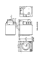
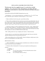
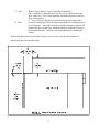
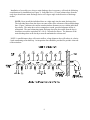
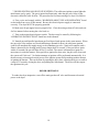
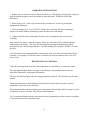
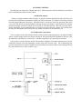
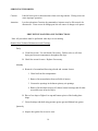
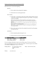
8514-046-001F
July 2013
OPERATOR’S MANUAL
for COIN COMPACT DRYER
The dryer must not be stored or installed where it will be exposed to water and/or weather.
WARNING: For your safety the information in this manual must be followed to
minimize the risk of fire or explosion or to prevent property damage, personal
injury or death.
-Do not store or use gasoline or other flammable vapors and liquids in the vicinity of
this or any other appliance.
-WHAT TO DO IF YOU SMELL GAS
-Do not try to light any appliance.
-Do not touch any electrical switch: do not use any telephone in your building.
-Clear the room, building or area of all occupants.
-Immediately call your gas supplier from a neighbor’s telephone. Follow the
gas supplier’s instructions.
-If you cannot reach your gas supplier, call the fire department.
Installation and service must be performed by a qualified installer, service agency or
the gas supplier.
You, the purchaser, must post in a prominent location instructions to be followed in the event the user smells
gas. Consult your local gas supplier for procedure to be followed if the odor of gas is present.
Post the following “For Your Safety” caution in a prominent location:
FOR YOUR SAFETY
Do not store or use gasoline or other flammable vapors or liquids in the vicinity of this or any other appliance.
FOR YOUR SAFETY
THIS MACHINE IS FOR DRYING ONLY FABRICS CLEANED IN WATER. To
avoid possibility of fire, including spontaneous combustion, do not dry oiled floor mops, items
containing foam rubber or similarly textured rubberlike materials or any material on which you
have used a cleaning solvent or which contains flammable liquids or solids (such as gasoline,
kerosene, waxes, etc.)
It is important that you read this Manual and retain it for future reference.
For service or replacement parts, contact the distributor in your area or:
Dexter Laundry, Inc
2211 W. Grimes
Fairfield, Iowa 52556, USA
French Language Warnings
AVERTISSEMENT. Assurez-vous de bien suivre les instructions données dans cette
notice pour réduire au minimum le risque d’incendie ou d’explosion ou pour éviter
tout dommage matériel, toute blessure ou la mort.
Ne pas entreposer ni utiliser d’essence ni d’autres vapeurs ou liquides inflammables dans
le voisinage de cet appareil ou de tout autre appareil.
I. QUE FAIRE SI VOUS SENTEZ UNE ODEUR DE GAZ:
·
·
·
·
·
Ne pas tenter d’allumer d’appareil.
Ne touchez à aucun interrupteur. Ne pas vous servir des téléphones se trouvant
dans le bâtiment oú vous vous trouvez.
Évacuez la pièce, le bâtiment ou la zone.
Appelez immédiatement votre fournisseour de gaz depuis un voisin. Suivez les
instructions du fournisseur.
Si vous ne pouvez rejoindre le founisseur de gaz, appelez le service des
incendies.
L’installation et l’entretien doivent être assurés par un installateur ou un service d’entretien
qualifié ou par le fournisseur de gaz.
POUR VOTRE SÉCURITÉ
Ne pas enteposer ni utiliser d’essence ni d’autres
vapeurs ou liquides inflammables dan le voisinage
de cet appareil ou de tout autre appareil.
2
TABLE OF CONTENTS
Page No.
Warnings about use and operation ...................................................................................... 3
Installation Instructions ................................................................................................5, 6, 7
Dryer Shutdown .................................................................................................................10
Operating Instructions.........................................................................................................11
Preventative Maintenance Instructions................................................................................16
ILLUSTRATIONS
Figure 1 - Dryer Dimensions .................................................................................................4
Figure 2 - Vertical Clearance Dimensions ............................................................................6
Figure 3 - Dryer Exhausting ..................................................................................................9
WARNINGS ABOUT USE AND OPERATION
It is ABSOLUTELY ESSENTIAL that the dryer be grounded to a known earth (zero)
ground. This is not only for personal safety, but is necessary for proper operation.
KEEP SHIELDS, GUARDS AND COVERS IN PLACE. These safety devices are
provided to protect everyone from injury.
A DRYER SHOULD BE CONNECTED TO POWER FOR THREE (3) MINUTES
before it is operated or before a program change is made. Operation or program changes, which
occur during this "power up" period, are subject to loss in case of power interruption. After the
initial three minutes, all programmed data is protected from power interruptions of any length
and the customer's individual cycle is protected up to 3 seconds. This is done without batteries.
LEAVE THE ELECTRICAL POWER TO THE DRYER ON AT ALL TIMES except
when necessary for service or other similar activities. The hour meter function adds only full
hours to its reading. If the power is shut off every night, any fraction of an hour of time that is on
the machine at that time will be lost. Turning the power off every night could also have some
effect on the long-term life of the memory after a number of years. Turning power off
occasionally won’t affect the unit.
THIS DRYER IS EQUIPPED WITH A MANUALLY RESETTABLE OVERTEMPERATURE THERMOSTAT located on the end of the burner housing below the gas valve.
Should the dryer cease to heat, reset the thermostat by inserting a wooden (nonconductive)
pencil or dowel through the guide bushing in the cover. Should the thermostat continue to trip,
the dryer must be inspected by a qualified service person.
CHECK THIS THERMOSTAT WHEN INSTALLING DRYER to assure it is not
tripped. Impacts, such as rough handling in shipment, may trip the thermostat. It may be reset by
inserting a wooden (nonconductive) pencil or dowel through the guide bushing in the cover.
3
4
INSTALLATION AND OPERATING INSTRUCTIONS
This dryer may have been supplied as part of a washer/dryer stacked
appliance. If so, refer to the washer instructions for uncrating and hard
mounting the stacked unit to a concrete floor and observe the dryer clearances
listed below.
UNCRATING AND PLACING DRYER (Stand alone dryer unit):
Tools Required: ½ in. hex socket and ratchet driver, wood block 4 in. or 5 in. (102-127 mm)
thick, a knife and a groove joint pliers, which will open to 1 3/8 in. (35 mm).
1. Remove and discard stretch-wrap, posts, cap and inner packing.
2. The crate base is attached to the dryer by (4) cap screws driven upward from below the crate
base. Remove crate base from dryer, by tipping dryer sidewise and place block under crate base
rail in center of dryer. Using a ratchet and ½ in. hex socket, remove and discard (2) crating bolts
from side, which is raised. Remove block from under crate base. Repeat for other side.
3. Install the leveling legs, which are shipped inside the dryer drum. Using a walking motion,
move dryer sideways about 6 in. (152 mm) off crate base. Tip dryer up and place block under
edge of dryer. Thread two leveling legs about two-thirds into the T-nuts on the base from which
the crating bolts were removed. Remove block from under dryer.
With a walking motion move dryer completely off crate base. Discard crate base.
Tip dryer sidewise, as previously done, and place block under edge of dryer on raised side.
Thread leveling legs into nuts as was done for the first side.
Slide unit into position where it will be installed. Adjust leveling legs, using the groove joint
pliers, to level and align dryer with adjacent units.
DRYER INSTALLATION
1. CODE CONFORMITY: All commercial dryer installations must conform to the local and
national codes for the location of installation.
2. INSTALLATION CLEARANCES: This unit may be installed at the following alcove
clearance.
I. Left Side 0
II. Right Side 0
III. Back
18 in. (457 mm) clearance is necessary behind the motors to allow
servicing and maintenance.
IV. Front
48 in. (1220 mm) to allow use of dryer.
5
V. Top
VI. Floor
Refer to figure labeled “Vertical Clearance Dimensions”.
AB. 0 clearance is allowable at the top; 4 in. (102 mm) back from the
front. However 1/4 in. (6 mm) clearance should be allowed in case the
dryer needs moving.
C. 10 in. (254 mm) clearance is required from top at all other points.
If used as a stand alone dryer, this unit is intended to be installed upon an
elevated surface. The surface must be of suitable strength to support 450
pounds (205 kg), and the dryer should be bolted or anchored to prevent
horizontal movement. The dryer may be installed upon a combustible
surface.
Refer to the label attached to the Belt Guard on the rear of the dryer for other installation
information and start-up instructions.
6
3. MAKE-UP AIR. Adequate make-up air, 440 CFM (12.5 m3/min.), must be supplied to
replace air exhausted by dryers on all types of installations. Provide a minimum of 1 sq. ft.
(.14 m2) make-up air opening to outside for each dryer. This is a net requirement of effective area.
Screens, grills or louvers, which will restrict the flow of air, must be considered. Consult the
supplier to determine the free area equivalent for the grill being used.
The source of make-up air should be located sufficiently away from the dryers to allow an even
airflow to the air intakes of all dryers. Multiple openings should be provided.
NOTE: The following considerations must be observed for gas dryer installation where dry
cleaners are installed.
The sources of all make-up air and room ventilation air movement to all dryers must be located
away from any dry cleaners. This is necessary so that solvent vapors will not be drawn into the
dryer inlet ducts. Dry cleaner solvent vapors will decompose in contact with open flame such as
the gas flame present in clothes dryers. The decomposition products are highly corrosive and will
cause damage to the dryer(s) ducts and clothes loads.
4. ELECTRICAL REQUIREMENTS. The electrical power requirements necessary to operate
the unit satisfactorily are listed on the serial plate located on the back panel of each dryer. The
electrical connection should be made to the terminal board, on the rear of the unit in the upper
control box using copper conductors of 15A minimum capacity. It is absolutely necessary that the
dryer be grounded to a known (earth) ground.
The installation must meet the National Electrical Requirements of the country of installation.
Individual 15A circuit breakers for each dryer are required. The installer must provide a
disconnect switch which will interrupt both lines. It may be a local or national requirement to
provide an electrical interruption switch visible and accessible from the room in which the dryer is
installed. The wiring diagram is located on the belt guard on the back of the dryer.
5. GAS REQUIREMENTS. The complete gas requirements necessary to operate the dryer
satisfactorily are listed on the serial plate located on the back panel of the dryer.
The inlet gas connection to the unit is ½ in. NPT pipe thread. However, the size of the piping to
supply the dryer should be determined by reference to national installation practice and
consultation with the local gas supplier.
A joint compound resistant to all fuel gases must be employed in making threaded pipe
connections.
A drip tee should be provided in the unit gas piping to catch dirt and other foreign articles.
All pipe connections should be checked for leakage with soap solution. Never check with an
open flame.
7
CAUTION: The dryer and its individual shutoff valve must be disconnected from the gas supply
piping system during any pressure testing of that system at test pressures in excess of ½ psig
(35 mbar). The dryer must be isolated from the gas supply piping system by closing its individual
manual shutoff valve during any pressure testing of the gas supply piping system at test pressures
equal to or less than ½ psig (35 mbar).
6. EXHAUST INSTALLATION. (Refer to Figure 3 at the end of section 6.) Exhausting of the
dryer(s) should be planned and constructed so that no air restrictions occur. Any restriction due to
pipe size or type of installation can cause slow drying time, excessive heat, and lint in the room.
From an operational standpoint, incorrect or inadequate exhausting can cause a cycling of the
high limit thermostat, which shuts off the main burners and results in inefficient drying.
Individual exhausting of the dryers is recommended. All heat, moisture, and lint should be
exhausted outside by attaching a pipe of the proper diameter to the dryer adapter collars and
extending it out through an outside wall. This pipe must be very smooth on the inside, as rough
surfaces tend to collect lint, which will eventually clog the duct and prevent the dryer from
exhausting properly. All elbows must be smooth on the inside. All joints must be made so the
exhaust end of one pipe is inside the next one downstream. The addition of an exhaust pipe tends
to reduce the amount of air the blower can exhaust. This does not affect the dryer operation if
held within practical limits. For the most efficient operation, it is recommended that no more than
14 ft. (4.25 m) of straight 6 in. (152 mm) diameter pipe with two right angle elbows be used for
each cylinder.
If the exhaust pipe passes through a wall, a metal sleeve of slightly larger diameter should be set
in the wall and the exhaust pipe passed through this sleeve. This practice is required by some
local codes and is recommended in all cases to protect the wall.
This type of installation should have a means provided to prevent rain and high winds from
entering the exhaust when the dryer is not in use. A hood with a hinged damper can be used for
this purpose. Another method would be to point the outlet end of the pipe downward to prevent
entrance of wind and rain. In either case, the outlet should be kept clear, by at least 24 in. (610
mm) of any objects, which would cause air restriction.
Provide a screen or grill over the termination of the exhaust or flue outlet such as will prevent the
entry of a ball of 5/8 (16 mm) in diameter while the machine is not operating but will allow entry
of a ball 1/4 (6 mm) in diameter while operating.
When exhausting a dryer straight up through a roof, the overall length of the duct has the same
limits as exhausting through a wall. A rain cap must be placed on top of the exhaust and must be
of such a type as to be free from clogging. The type using a cone shaped “roof” over the pipe is
suitable for this application.
Exhausting the dryer into a chimney or under a building is not permitted. In either case there is a
danger of lint buildup, which can be highly combustible.
8
Installation of several dryers, where a main discharge duct is necessary, will need the following
considerations for installation (see Figure 3). Individual 6 in. (152 mm) exhaust ducts from the
each dryer should enter main discharge duct at a 45-degree angle in the direction of discharge
airflow.
NOTE: Never install the individual ducts at a right angle into the main discharge duct.
The individual ducts from the dryers can enter at the sides or bottom of the main discharge
duct. Figure 3 indicates the various round main duct diameters to use with the individual
dryer ducts. The main duct can be rectangular or round, provided adequate airflow is
maintained. The total exhausting (main discharge duct plus duct outlet from the dryer)
should not exceed the equivalent of 14 ft. (4.5 m) and two elbows. The diameter of the
main discharge duct at the last dryer must be maintained to exhaust end.
NOTE: A small diameter duct will restrict airflow; a large diameter duct will reduce air velocity
- both contributing to lint build up. An inspection door should be provided for periodic clean out
of the main duct.
9
7. DRYER IGNITION (SOLID STATE IGNITION). The solid-state ignition system lights the
main burner gas by spark. The gas is ignited and burns only when the gas-valve relay (in the
electronic controller) calls for heat. The procedure for first-time starting of a dryer is as follows:
A. First, review and comply with the “WARNINGS ABOUT USE AND OPERATION” found
on the inside front cover of this manual. Be sure the electrical power supply is connected
correctly. The dryer MUST be properly grounded.
B. Make sure all gas supply lines are purged of air. Close the main gas shut-off valve and wait
for five minutes before turning the valve back on.
C. Turn on the main electrical power switch. The dryer may be started by following the
“OPERATING INSTRUCTIONS” found later in this manual.
D. Natural gas and liquefied petroleum gas fired dryers both operate in the same manner. When
the gas-valve relay contacts are closed (indicating a demand for heat), the solid-state ignition
control will automatically supply energy to the redundant gas valve. Spark will continue until a
flame is detected by the sensing probe, but not longer than 10 seconds. If the gas fails to ignite
within 10 seconds, the gas will shut off for 15 seconds. The control will attempt to ignite two
more times in a similar manner. If the gas fails to ignite after three tries, the gas valve closes and
the system will “lock out”. No further attempts at ignition will be performed automatically. It is
then necessary to interrupt electrical power to the ignition system before making another attempt
at igniting the burners. This can be done by opening the dryer door, allowing the dryer to come to
a stop for 15 seconds, closing the door, and pushing the Start button. The dryer will then repeat
the ignition trial cycle.
DRYER SHUTDOWN
To render the dryer inoperative, turn off the main gas shut-off valve and disconnect electrical
power to the dryer.
10
OPERATING INSTRUCTIONS
1. Deposit coins to satisfy vend price display of idle dryer. Each deposit decreases the vend price
until the display changes to show the amount of time purchased. WARM or LOW light
illuminates.
2. Select drying cycle. Other cycle selections may be made now or later by pressing the
appropriate key (button).
3. Close the loading door. Press “START” and the dryer will start. The time remaining is
displayed in whole minutes (rounded up) and will count down each minute.
4. Clothes should be removed promptly after the cycle is completed to prevent excessive
wrinkling.
Once started, the “timer” cannot be stopped. However, extra coins will be acknowledged by
adding time to the display. The dryer may be stopped by opening the loading door, which
interrupts the drive motor and gas burners. Close the loading door and push “START” to restart
the dryer.
Cool-down time (owner programmable) is always part of the cycle time and is purchased by the
customer. For example, if cool-down time is 2 minutes, the last two minutes of the cycle will
have no heat.
DESCRIPTION OF CONTROLS
Credit for coins deposited, dryer time and temperature are controlled by an electronic control.
The large digital display shows vend price of an idle dryer, time purchased after coins are
deposited, temperature, and program information.
The three red indicator lights show the drying temperature selected. This selection may be made
anytime.
The drying temperature will be displayed when the start switch and the switch for selected
temperature are pressed at the same time.
All programmed data is protected from power interruption of any length, and the customer’s cycle
is protected for up to 3 seconds. This is done without batteries.
The 3 temperature buttons and the start button become programming switches when the controller
is in the program mode as described below.
11
PROGRAMMING:
All operating parameters (vend price, temperatures, cool-down times, etc.) are adjustable. There
are also several displays of information available from the controller (money audits, hours run,
and dryer temperature.)
The dryer is shipped ready for operation with the following pre-programmed data:
Temperature- HOT (or HIGH):
Temperature- MEDIUM:
Temperature- WARM (or LOW):
Vend Price:
Time for Left Coin Slot:
Time for Right Coin Slot:
Time for Free Vend:
Cool-down Time HOT (or HIGH):
Cool-down Time MEDIUM:
Cool-down Time WARM (or LOW):
Temperature Scale:
Decimal Point Display:
Seconds on Display:
175°F/ 78°C
150°F/ 63°C
125°F/ 48°C
25¢
3:20 (does not apply to single coin models)
8:00 (8 minutes for 25¢)
8:00
2:00
2:00
2:00
°F
ON
OFF
All of the above data can easily be changed by the owner. The changes are made by the 4 keys
or buttons on the front of the control panel.
CHANGING PROGRAM DATA
Put dryer in PROGRAM mode (see “Programming Instructions”). The dryer remains in the
PROGRAM mode until one of these actions occur:
·
·
The switch is actuated again.
The seventeenth step is completed, and the START switch is pushed following the
seventeenth step.
Programming is stopped for about a minute.
The loading door is closed.
·
·
·
Observe the displayed value in each step. If no change is required, press START to advance to
the next program step. If a change is required the values are made larger by the HOT (or HIGH)
button, smaller by the MED button. The hour meter and money audit can be reset to zero if
WARM (or LOW) is pressed.
Note: After any reset or program change, it is necessary to advance to the next step by pressing
START to enter the revision. OTHERWISE THE VALUE WILL REMAIN AS IT WAS
BEFORE THE ALTERATION.
12
TO CHANGE PROGRAMMED VALUES OR ZERO REGISTERS
1. Open the loading door.
2. Unlock the control tray, carefully slide the control tray assembly forward about three
inches. Press the program switch. (See Figure 4 “Top View of Controller”) Reinstall
and lock the controller.
The controller is now in the program mode at the “00" step, displaying the hours run by
the lower drum. (Refer to the table defining the steps.)
This value displayed can be reset to “0" or observed and left as is: Pressing the START
switch will advance the controller through the fifteen remaining steps allowing
observation or alteration.
Note that on any program change or reset it is necessary to advance to the next step by
pressing the START switch to enter the revision. Otherwise the value will remain as it
was before the alteration.
Figure 4 - Top View of Controller
13
ORDER OF PROGRAMMING STEPS
CYCLE
LIGHTS
DISPLAY
HOT or
HIGH
MEDIUM
WARM or
LOW
__ __
PROGRAMMING STEP
DESCRIPTION
OPTIONS/RANGE
HOUR METER
Displays hours of timer operation.
May be reset to zero
MONEY AUDIT
Value of coins deposited.
May be reset to zero.
HOT or
HIGH
__
TEMPERATURE: HOT or
HIGH
Median operating temp-Hot or
HIGH
150-190°F / 63 -87°C
MEDIUM
__
TEMPERATURE: MED
Median operating temp-Medium
120-170°F / 45-75°C
WARM or
LOW
__
TEMPERATURE: WARM or
LOW
Median operating temp-Warm or
LOW
110-150°F / 39-63°C
LEFT COIN VALUE
Value of coin for left acceptor in
1¢ increments.
0 through 9999 cents
RIGHT COIN VALUE
Value of coin for right acceptor in
1¢ increments
0 through 9999 cents
VEND PRICE
Amount required to start dryer in
1¢ increments.
0 through 9999 cents
TIME FOR LEFT COIN
Minutes and seconds credited for
one coin deposited in left acceptor.
0 through 99:55
(minutes : seconds)
TIME FOR RIGHT COIN
Minutes and seconds credited for
one coin deposited in right
acceptor.
0 through 99:55
(minutes : seconds)
TIME OF FREE VEND
Minutes and seconds of “free” dry.
Vend price set to 0.
0 through 99:55
(minutes : seconds)
__ __
__ __
__
__ __ __
__ __ __
__
HOT or
HIGH
__
__
COOL-DOWN TIME: HOT or
HIGH
Minutes and seconds of
cool-down: HOT or HIGH cycle
0 through 10 minutes
MEDIUM
__
__
COOL-DOWN TIME:
MEDIUM
Minutes and seconds of
cool -down: Med. cycle.
0 through 10 minutes
WARM or
LOW
__
__
COOL-DOWN TIME: WARM
or LOW
Minutes and seconds of
cool-down: WARM or LOW cycle.
0 through 10 minutes
TEMPERATURE SCALE
Sets temperature display to
or °C
F or C
DISPLAY: DECIMAL POINT
Displays decimal point in prices.
OFF or ON
DISPLAY: SECONDS
Displays time remaining in
minutes:00 or in minutes:seconds.
OFF or ON
14
°F
AVAILABLE OPTIONS
The following two features are available in the dryer. Disconnect power from the machine for two minutes
before modifying the machine for either option.
Anti-Wrinkle Option
The dryer is shipped with this feature defeated. As shipped, when the machine stops at the end of the cycle,
the load will sit motionless in the machine until the user removes the load. The feature is activated by removing
the small jumper indicated in the picture. When the feature is activated, it comes into operation at the end of
every cycle if the door is not opened within five minutes after the cycle finishes. At the end of this five-minute
period, the machine will turn on and run for 10 seconds to redistribute the load. This will occur after each 5minute interval that goes by without the door ever having been opened for up to 16 times. The opening of the
door any time during this period will prevent any further occurrences for the particular cycle.
Last Temperature Used Option
There is a jumper on the control for this feature as shown on the accompanying picture. As shipped, from the
factory, with the jumper in place, this feature is defeated. This means that at the beginning of each new cycle
the temperature will default to ‘warm or low’ if another temperature isn’t selected by the customer.
If the jumper is removed from the control, the operation is changed, so that when starting a new cycle, the
temperature remains at the last temperature selection used in the previous cycle. This would mean if the
previous customer has used a ‘HOT or HIGH’ selection and the next customer didn’t select anything different,
they also would receive a ‘HOT or HIGH’ cycle.
15
SERVICING THE DRYER
Caution:
Label all wires prior to disconnection when servicing controls. Wiring errors can
cause improper operation.
Attention.
Lors des opérations d’entrien des commandes, étiqueter tous les fils avant de les
déconnecter. Toute erreur de câblage peut être une source de danger et de panne.
PREVENTIVE MAINTENANCE INSTRUCTIONS
Note: All procedures must be performed when dryer is not running.
Routine Non-Technical Maintenance and Cleaning:
Daily
A. Clean lint screens. Use soft brush if necessary. Failure to do so will slow
drying and increase temperatures throughout the dryer.
B. Check lint screen for tears. Replace if necessary.
Monthly
A. Removal of accumulated lint using a brush and vacuum cleaner.
1. Clean lint from lint compartment.
2. Remove lint accumulation from end bells of motors.
3. Vacuum the openings in the burner primary air openings.
4. Remove lint and dust from top of cabinet, burner housings and all other
accessible areas in back of dryer.
B. Place a few drops of light oil on top and bottom pivots of the loading door
hinge.
C. Grease bearings and shaft using pressure grease gun and lithium base grease.
Quarterly
A. Inspect door gasket for excessive wear.
16
Maintenance Requiring Technical and Mechanical Skills:
(Disconnect power to dryer before beginning.)
Quarterly
A. Check tumbler shaft retaining bolt for tightness.
B. Check belts for wear needing replacement.
Semi-Annually
A. Clean burners. Note position of back panel of burner housing before removing
as the panel is slotted for adjustment of ignitor to top of burners. This spacing
is to be 5/16 in (8mm).
Mark position of panel on left and right burner side panels for reference.
Remove the burner-housing panel (wires can be left attached and panel left
hanging.)
Blow out burners and around vent opening and orifices with compressed air.
Replace panel in its original position.
Run the dryer to assure operation and ignition and purge any dislodged lint
from drying chamber.
B. Remove front panels and clean all accumulated lint and dirt from all openings
accessible from front.
ANNUALLY
A. Check intermediate pulley bearings for wear.
B. Check and remove any lint accumulation from exhaust system.
SERVICE PARTS
DRIVE BELT, MOTOR
DRIVE BELT, TUMBLER
LINT SCREEN FILTER
PART NUMBER
9040-077-001
9040-073-009
9555-057-002
For service and parts information, contact your local Dexter agent. To find your local Dexter
agent, use the Distributor Locator at the website shown below. If a Dexter agent is not available,
contact Dexter Laundry, Inc. directly as listed below:
Mailing Address:
Website:
2211 West Grimes Avenue
Fairfield, IA 52556
USA
www.dexter.com
17
Phone: 1-800-524-2954 (USA)