1
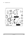
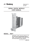
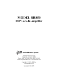
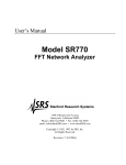
Audio Failsafe
Model AFS-3
– INSTALLATION AND OPERATION –
This documentation is valid for
Audio Failsafe hardware version 3.0 and software version 1.0
Nashville, Tennessee • 615-228-3500
Table of Contents
Section I – Safety Information / Warranty
1.1
Safety Information
Page Number
1.1
Section 2 – System Descriptions
2.1
2.2
2.3
2.3.1
2.3.2
2.3.3
General Description
Physical Description
Electrical Description
Front Panel Indicators
Normal/Defeat Switch
Delay Adjustment
2.1
2.2
2.1
2.1
2.1
2.1
Section 3 – Installation
3.1
3.2
3.2.1
3.2.2
3.2.3
3.2.4
3.2.5
3.2.6
3.2.7
3.2.8
3.2.9
3.2.10
System Includes
Installing the Unit
Screw-Terminal Connectors
Power Supply Connection
Audio Inputs
Delay Adjustment
Relay Connections
Logic Voltage Output
Audible Alert Enable/Disable
Audio/Silence Detector
Power Supply Loss
Safety Considerations
3.1
3.1
3.1
3.1
3.1
3.2
3.2
3.3
3.3
3.3
3.4
3.4
Section 4 – Circuit Description and Repair
4.1
4.2
4.2.1
4.2.2
4.2.3
4.2.4
4.2.5
4.2.6
Circuit Description
Factory Service Policy
Factory Warranty
Factory Return Policy
Factory Service Policy
Warranty Service
Service Rates
Instructions for Factory Service
4.1
4.1
4.1
4.1
4.2
4.2
4.2
4.2
Section 5 – Specifications
5.1
5.2
5.3
5.4
5.5
AFS-3
General Specifications
Audio Input
Relay Output
Schematic Diagram
Component Layout
5.1
5.1
5.1
5.2
5.3
Table of Contents
i
Section 1 — Safety Information
1.1
Safety Information
!
The AFS-3 Audio Failsafe should be installed only by qualified technical personnel. An attempt to install
this device by a person who is not technically qualified could result in a hazardous condition to the
installer or other personnel, and/or damage to the AFS-3 or other equipment. Please ensure that proper
safety precautions have been made before installing this device.
If the AFS-3 is connected so that loss of audio turns a transmitter off, the return of audio could turn the
transmitter back on. Operating and maintenance personnel should be mindful of this possibility and be
sure the transmitter is rendered inoperable before servicing the transmitter, antenna, or associated
equipment.
The purchaser and user of the Sine Systems AFS-3 Audio Failsafe bears the sole responsibility for determining
suitability of this equipment for their intended use.
The AFS-3, as any electronic device, can fail in unexpected ways and without warning. Do not use the AFS-3 in
applications where a life-threatening condition could result if it were to fail. Sine Systems, Inc. cannot be held
responsible for damages, either direct or indirect, resulting from use of this equipment.
Even though the AFS-3 is powered by 12 volts AC from a "wall plug" transformer, failure of this transformer could
cause dangerous and potentially lethal voltages to become present. Only the supplied transformer should be used.
The AFS-3 is designed for indoor use in a dry location. Installation and operation in other locations could be
hazardous.
AFS-3
Safety Information
page 1.1
Section 2 — System Descriptions
2.1
General Description
The AFS-3 monitors one or two audio signals and provides a relay contact closure as long as at least one of the audio
signals is present. When no audio is present for a preset period (adjustable from 30 seconds to 5 minutes), the relay
contact opens and remains open until one or both of the audio signals return.
A typical application of the AFS-3 is to provide alternate control for a remotely controlled broadcast transmitter.
When appropriately installed, the AFS-3 can be used to turn off a transmitter by silencing the audio feed to the
transmitter. This procedure would normally be used only when the normal remote control device has failed.
2.2
Physical Description
The AFS-3 is contained in a 19 inch wide rack mounted case, 1.75 inches high. The front panel contains indicator
LED’s and a switch to force closure of the relay contacts and defeat operation of the AFS-3. The rear panel contains
“pluggable” screw-terminal connectors for connecting the audio inputs, power, and relay connections.
Power
Enabled
Audio
Alert
Dual-Channel Audio Failsafe model AFS-3
Normal
Defeat
Remote Facilites Controller Accessory
Sine Systems
, inc
Figure 2.1; AFS-3 front panel
2.3
Electrical Description
2.3.1
Front-Panel Indicators
The front panel of the Audio Failsafe contains four LED indicators:
•
•
•
•
2.3.2
"Power" illuminates when the AFS-3 has power
"Enabled" illuminates when the Normal/Defeat switch is in the Normal position
"Audio" illuminates when the AFS-3 detects audio
"Alert" illuminates when the system is in alert condition
Normal/Defeat Switch
The front panel of the Audio Failsafe contains a pushbutton switch. In the Normal position the switch allows the relay
to follow the audio. When audio is present the relay closes (contact between NO and C). When audio is absent for the
preset delay period, the relay relaxes (no contact between NO and C). In the Defeat position, audio is still detected
but the relay is forced into the relaxed position. This logic may be reversed by using the normally closed (NC) contact
in place of the normally open (NO) contact.
2.3.3
Delay Adjustment
The rear panel of the AFS-3 has a rotary switch that adjusts the detection delay. The delay setting determines the
length of time that must elapse for the alert to occur. For example, if the delay is set to 30 seconds then the system
must detect silence continuously for 30 seconds before the alert condition will be triggered.
AFS-3
System Descriptions
page 2.1
Section 3 — Installation
!
The AFS-3 Audio Failsafe should be installed only by qualified technical personnel. An attempt to install
this device by a person who is not technically qualified could result in a hazardous condition to the
installer or other personnel, and/or damage to the AFS-3 or other equipment. Please ensure that proper
safety precautions have been made before installing this device.
3.1
System Includes
The Audio Failsafe package contains these items:
•
•
•
3.2
Audio Failsafe model AFS-3
12 volt AC wall-plug transformer
Operation Manual
Installing the Unit
The Audio Failsafe is designed to be placed almost anywhere. It generates little heat and can be mounted in just
about any convenient location where the ambient temperature does not exceed 120°F.
3.2.1
Screw-Terminal Connectors
All electrical connections to the Audio Failsafe are made through a pair of five position connectors on the rear panel.
Pluggable, screw-terminal connectors are supplied. Note that these can be removed from the panel by pulling them
straight out. This makes wiring and removal very easy.
3.2.2
Power Supply Connection
The Audio Failsafe is powered by 12 volts AC. The included wall-plug power transformer should be used. The leads of
this transformer should be stripped and connected to the terminals marked "12 VAC" on the rear panel of the AFS-3.
If the supplied transformer has a connector on the end of the wire, simply cut the connector off and discard it.
3.2.3
Audio Inputs
Audio connections are made to the AFS-3 through the screw-terminal connector on the left hand side of the rear
panel. There is an "A" channel input and a "B" channel input. Either one or both channels may be used. If two stereo
channels are connected to the inputs, note the polarity of the audio connections or signal cancellation will result. If
only one audio source is used, connect it to either input and leave the other input disconnected. The optional "Gnd"
terminal is connected to the internal circuit ground and it is not chassis ground.
AFS-3
Installation
page 3.1
Generally, the most desirable location to "tap" the audio signal for use by the AFS-3 is a point where the signal level is
somewhere between 0 dBm and +10 dBm. This could be the output of a discrete STL, the output of audio processing
equipment, or the transmitter's audio input terminals. Telephone line audio is not a good source for the AFS-3 since
the audio level of telephone lines is generally about -30 dBm. The output of a processing device would be a good
monitoring point in such installations. The audio input impedance of the AFS-3 is approximately 50 KΩ so bridging the
AFS-3 across a program source usually has no significant effect.
After installing the AFS-3 make sure that the "Audio" LED does in fact turn off when audio is lost. Otherwise the
timing interval will never begin and the AFS-3 will not work as intended.
3.2.4
Delay Adjustment
The period of time required after the loss of audio before the alert condition is triggered is set at the factory to 2.5
minutes. This can be adjusted with the 10 position rotary switch on the rear panel of the AFS-3. The adjustment
range is 30 seconds to 5.0 minutes in 30 second increments.
Sine Systems, inc
Audio Inputs
A- A+ Gnd B+ B-
Delay Adjust
(minutes)
2.5
2.0
1.5
1.0
0.5
Relay Out • Power
NO C NC 12VAC
3.0
3.5
4.0
4.5
5.0
Dual-Channel Audio Failsafe model AFS-3 • Sine Systems, Inc. • Nashville, Tennessee
Figure 3.1; AFS-3 rear panel
3.2.5
Relay Connections
The contacts of the internal relay are accessed through the terminals labeled "Relay Out" on the rear panel. As
shipped from the factory the output relay contacts are dry and can be used to make/break contact in an external
circuit. When audio is present the normally closed (NC) and common (C) terminals make contact. When the failsafe
is in alert condition the normally open (NO) and common (C) terminals make contact.
!
Although the relay contacts are rated at 120 volts AC, it is not recommended that 120 volts AC be
connected to the AFS-3. The screw-terminal connectors have several exposed points that could produce
a dangerous or even lethal shock if they were contacted. Low voltage AC or DC is much safer and
eliminates the potential for a shock hazard.
AFS-3
Installation
page 3.2
3.2.6
Logic Voltage Output
If the AFS-3 will be connected to an external sensing device, there are jumpers inside the AFS-3 that can be set so
that the output relay switches a logic voltage to indicate an alert condition.
Jumper positions JP2-4 set the logic voltage output. No jumpers are installed at these positions at the factory and
the relay contacts are dry--no voltage. JP4 places +5VDC (current limited throuh a 2.2K pull up resistor) on the
common (C) relay contact. JP2 and JP3 ground the normally closed (NC) and normally open (NO) relay contacts
respectively.
To generate a logic high (+5VDC) in the alert condition, place a jumper on JP2 so that the logic voltage normally
bleeds off through the internal resistor to ground through the NC contact. When the relay is energized during the alert
condition the contact to ground will be broken and the logic voltage will rise to +5VDC. Reverse the logic by placing a
jumper at JP3 instead of JP2.
3.2.7
Audible Alert Enable/Disable
Enable the audible alert inside the AFS-3 by placing a jumper at position JP1. Disable the audible alert by removing
the jumper at position JP1. The audible alert is enabled by default.
The audible alert can be constant or pulsing. Place a jumper at position JP5 to make the alert sound constant.
Remove the jumper at position JP5 to make the alert sound pulse. The alert pulses by default.
Figure 3.2; AFS-3 internal jumper locations
3.2.8
Audio/Silence Detector
Normally the AFS-3 senses loss of audio. When all audio is lost for the delay period the failsafe triggers the alert
condition. The system can be set to sense audio presence instead of silence by placing a jumper at position JP6. In
this “reverse” mode the failsafe triggers an alert when audio (rather than silence) is present for the delay period.
AFS-3
Installation
page 3.3
3.2.9
Power Supply Loss
Note that if power is lost to the AFS-3 the output relay will relax because there is no voltage to energize the coil.
Additionally, there will be no logic voltage output since there is no power supply. Consider this and take necessary
steps if it becomes necessary to disconnect power from the AFS-3.
!
3.2.10 Safety Considerations
If the AFS-3 is connected so that loss of audio turns a transmitter off, the return of audio could turn the
transmitter back on. Operating and maintenance personnel should be mindful of this possibility and be
sure the transmitter is rendered inoperable before maintenance is begun on the transmitter, antenna, or
associated equipment.
AFS-3
Installation
page 3.4
Section 4 — Circuit Description and Repair
4.1
Circuit Description
The first two sections of U1 are balanced audio input stages of the "A" and "B" audio inputs. Overall, these have a
gain of 0.33 (loss). The next stage combines the two channels and has a gain of 10. Capacitors C1 through C12
provide high frequency roll-off and RFI immunity. A rectifier, short term integrator (about 1 second), and comparator
follow. When audio is present, the "Audio" LED is turned on by this comparator. U2 is a small microcontroller that
receives a logic-level signal from the audio comparitor. The microcontroller performs the timing functions and
controls the output peripheral components (LED’s, relay, audible alert).
4.2
Factory Service Policy
These policies are effective August 1999 and are subject to change without prior notice.
4.2.1
Factory Warranty
Sine Systems, Inc. guarantees our products to be free from manufacturing defect for a period of one year from the
original date of purchase from Sine Systems, Inc. This warranty covers the parts and labor necessary to repair the
product to factory specifications. This warranty does not cover damage by lightning, normal wear, misuse, neglect,
improper installation, failure to follow instructions, accidents, alterations, unauthorized repair, damage during transit,
fire, flood, tornado, hurricane or acts of God and/or nature.
4.2.2
Factory Return Policy
The factory return policy only applies to equipment purchased directly from Sine Systems, Inc. Equipment
purchased through a third party (dealer) is subject to the return policy of the dealer and arrangements for return or
exchange must be handled through the dealer.
Sine Systems policy on returns and exchanges with the factory is broken down according to the following schedule:
30 days “no questions asked”
During the first thirty days from the date that equipment ships from our factory we will accept it
back for a full refund less shipping charges provided that the equipment is still in new, resellable
condition with no cosmetic damage. This does not constitute an evaluation program. It is for
legitimate purchases only.
less than 60 days, may be returned less 15% restocking fee
Between 31 and 60 days from the time we ship the equipment, we will accept unmodified equipment
back for a refund less shipping charges and 15% of the invoice cost. This is to cover the cost of
restocking the items which must then be sold at a discount as reconditioned instead of new.
no return after 60 days
We will recondition the equipment for you according to our repair rates but we will not accept it for
refund or exchange after 60 days from the initial purchase.
AFS-3
Circuit Description and Repair
page 4.1
4.2.3
Factory Service Policy
Sine Systems is proud to offer same day repair service on all of our products. When we receive damaged equipment,
we will repair it and ship it back the same day it arrives. Because we offer immediate service, we do not send loaner
equipment. If we cannot immediately repair equipment and return it, we may ship a loaner unit at our discretion.
While we do not require prior authorization on repairs, we suggest that you verify our shipping address before
returning equipment for repair. Sine Systems is not responsible for items lost in transport or delivered to the wrong
address. Emergency service may be made available on weekends or holidays, at our discretion, if arrangements are
made with us in advance.
4.2.4
Warranty Service
There is no charge for repair service on items covered under warranty. You are responsible for shipping charges to
return damaged equipment to us for repair. Damage due to negligence, lightning or other acts of nature are not
covered under warranty.
4.2.5
Service Rates
For service not covered under warranty we have a flat rate repair fee. Flat rate repairs cover only components that
fail electrically. Mechanical damage will be assessed on a per repair basis. Repair charges typically fall into one of
these categories. Shipping fees are not covered in the repair rate.
Minor programming adjustments or no damage, $50 plus shipping
Sometimes a system works exactly like it is supposed to when we get it or it can be fixed through a
simple adjustment in firmware. We will do our best to identify intermittent hardware problems and
correct them. The fee covers the time it takes our technician to thoroughly inspect and test the
equipment.
Minor repairs are up to $150 plus shipping
Five or fewer defective components are replaced in a minor to moderate repair. This accounts for
most of our repairs. These repairs may cost less depending on the components replaced and the
amount of time required to complete the repair.
Moderate repairs are $250 plus shipping
Six to ten defective components are replaced in a major repair. Again, we may charge less
depending on the components replaced and the amount of time required to complete repairs.
Major repairs cost more than $250 plus shipping
This occurs rarely but it can happen. If the equipment has blown traces and scorch marks from
burned components, it’s a safe bet that it will take several components and quite a bit of bench time
to repair. We assess this type of repair on a per incident basis.
Damaged beyond recognition, assessed on a per case basis
Hopefully you have insurance. In cases where the board is so badly damaged that it is not worth
repairing we may, at our discretion, offer to replace the destroyed circuit board. The options and
costs vary widely in these cases so we will call with options.
AFS-3
Circuit Description and Repair
page 4.2
All repairs must be billed to a credit card or shipped COD. Specify which you prefer with your request for service. At
your request, we will call with the total amount of the repair (including applicable shipping charges) so that suitable
payment can be arranged before a COD shipment. If you need a COD total, do not forget to include a telephone
number where you can be contacted.
4.2.6
Instructions for Factory Service
Please include a note with any specific information available about the equipment failure as an aid to our technicians.
Pack equipment carefully to avoid further damage in shipping. We are not responsible for damage during transport.
When returning a system with multiple components, we strongly suggest that you return the entire system. We will
repair the parts that are returned but lightning is rarely selective enough to damage only a single part of a system.
Be sure to include a street address for return shipping by UPS. The repair will be delayed if you neglect to give us
enough information to return your equipment--this actually happens! If you prefer a carrier other than UPS or wish us
to bill to your shipping account, we can usually accommodate these requests. Many carriers do not accept COD
shipments so credit card billing may be required for carriers other than UPS. If you do not specify otherwise, return
shipments will be made by the UPS equivalent of the received shipping method (i.e. Ground shipment, 2nd Day,
Overnight).
We suggest that you verify our shipping address before sending equipment for repair. Same day service does not
apply if you ship to an incorrect address and/or the carrier delivers the equipment too late in the day for repairs to be
completed. Sine Systems is not responsible for equipment that is not delivered to our factory. It will be your
responsibility to contact the carrier to retrieve your improperly delivered equipment.
AFS-3
Circuit Description and Repair
page 4.3
Section 5 — Specifications
5.1
General
Operation
Output relay contact closes (NO and C connected) within one second after audio becomes present
and remains closed as long as audio is present. Output relay contact opens (NC and C connected)
at the end of an adjustable delay period after audio becomes absent.
Delay Range
30 seconds to 5.0 minutes in 30 second increments
Indicators
Power (Green LED)
Enabled (Green LED)
Audio (Green LED)
Alert (Red LED)
Ports
Power/Output
Audio In
Switches
In the Normal (out) position the AFS is enabled and the relay closure follows the audio input. In the
Defeat (in) position the system is disabled and the relay is forced into the relaxed state.
Power
12 Volts AC, 0.25 amps max.
Dimensions
19” (w) x 6.5” (d) x 1.75” (h)
Weight
1.5 lbs.
5.2
Audio Input
Inputs
Type
Impedance
Sensitivity
5.3
Relay Output
Contacts
AFS-3
2 (combined)
Actively Balanced
60 K Ohms
-16 dBv
Form C contacts rated at 120 volts AC, 5 amps resistive / 2 amps inductive
Specifications
page 5.1
5.5
AFS-3
Component Layout
Specifications
page 5.3
5.6 Parts List (hardware revision 1.00)
Quantity
Part Description and Value
AFS-3
board, PC, AFS-3, Rev. 1
1
capacitor, aluminum, radial, 1,000 µF, 25v
1
capacitor, aluminum, radial, 10 µF, 16v/short
1
capacitor, aluminum, radial, 100 µF, 16v/short
1
capacitor, monolythic ceramic, 0.1 µF, .1" spacing
1
capacitor, monolythic ceramic, 100 pF, .1" spacing
4
capacitor, monolythic ceramic, 1000 pF, .1" spacing
4
capacitor, monolythic ceramic, 27 pF, .1" spacing
2
capacitor, polyester, 0.047µF, 50V, 5%
4
connector, pin-plug, female, 0.1", 2, shorting plug
1
connector, screw terminal, 5.0 mm, 5, plugable
2
connector pins, pin-plug, male, 0.1", 40 x 2, 0.23 gold up/.015 tin dn
6
connector pins, screw terminal, 5.0 mm, 5 (5x1), PCB, 90°
2
crystal, 3.579 MHz, 18 pF parallel, HC-49S
1
diode, bridge rectifier, 200 V/1 A,
1
diode, general purpose, 600 V/1 A, 1N4005
3
diode, zener, 5.1 V/1 W, 1N4733A
2
enclosure, assembly, platinum, T1 MicroPak, 5.0"
1
enclosure part, overlay, lexan, printed for AFS-3
1
enclosure part, rack panel, aluminum, painted for AFS-2
1
enclosure part, rear panel, T1 MicroPak, punched for AFS-2 (overlay)
1
fuse, polyswitch, resettable, 0.4 amp, 60 V
1
hardware, nut, locknut, hex, 4-40, stainless
1
hardware, screw, pan head, 4-40 x 3/8", stainless
1
heatsink, TO-220, 0.52" x 0.50" x 0.75", vert, solder
1
integrated circuit, low voltage interrupt, MN1381-S, CMOS output
1
integrated circuit, microprocessor, MC68HC705J1ACP,
1
integrated circuit, op amp, quad, LM324N,
1
integrated circuit, transistor, NPN, PN2222A, TO-92
3
integrated circuit, voltage regulator, LM78M05FA, +5V DC/0.5 A
1
LED, 5mm, long, green, 90°
3
LED, 5mm, long, red, 90°
1
miscellaneous, sonalert, piezo, 3-20 volt DC, 75dB @ 12V
1
relay, general purpose, 5A contact, 5 volt DC, form 1C
1
resistor, carbon film, 1/4W, 10, 5%
1
resistor, carbon film, 1/4W, 150, 5%
2
resistor, carbon film, 1/4W, 2.2K, 5%
1
resistor, carbon film, 1/4W, 51K, 5%
1
resistor, SIP, 4 x 1K, isolated
1
resistor, SIP, 4 x 2.2K, isolated
1
resistor, SIP, 4 x 220, isolated
1
resistor, SIP, 4 x 470K, isolated
1
resistor, SIP, 4 x 47K, isolated
2
Specificiations
Quantity
Part Description and Value
AFS-3
resistor, SIP, 7 x 4.7K, common
1
socket, DIP, 14,
1
socket, DIP, 20,
1
switch, cap for C&K latched pushbutton, light gray, round
1
switch, DIP, rotary, 10 position, front adjust
1
switch, pushbutton, latched, DPDT, PCB, 90°
1
transformer, wall plug, 12V AC, 1.0 A / 18W
1
varistor, metal oxide, 18 VDC, 14 VAC
1
Specificiations