1
Microsoft Exchange Server 2007 Unified Messaging
PBX Configuration Note:
Mitel 3300 with AudioCodes Mediant 1000/2000
using T1 QSIG
By
: AudioCodes
Updated Since : 2007-06-05
READ THIS BEFORE YOU PROCEED
This document is for informational purposes only and is provided “AS IS”. Microsoft, its partners and
vendors cannot verify the accuracy of this information and take no responsibility for the content of this
document. MICROSOFT, ITS PARTNERS AND VENDORS MAKE NO WARRANTIES, EXPRESS,
IMPLIED OR STATUTORY, AS TO THE INFORMATION IN THIS DOCUMENT.
1
Content
This document describes the configuration required to setup Mitel 3300 and AudioCodes Mediant
1000/2000 using T1 QSIG as the telephony signaling protocol. It also contains the results of the
interoperability testing of Microsoft Exchange 2007 Unified Messaging based on this setup.
Intended Audience
This document is intended for Systems Integrators with significant telephony knowledge.
Technical Support
The information contained within this document has been provided by Microsoft, its partners or
equipment manufacturers and is provided AS IS. This document contains information about how to
modify the configuration of your PBX or VoIP gateway. Improper configuration may result in the loss
of service of the PBX or gateway. Microsoft is unable to provide support or assistance with the
configuration or troubleshooting of components described within. Microsoft recommends readers to
engage the service of an Microsoft Exchange 2007 Unified Messaging Specialist or the manufacturers
of the equipment(s) described within to assist with the planning and deployment of Exchange Unified
Messaging.
Microsoft Exchange 2007 Unified Messaging (UM) Specialists
These are Systems Integrators who have attended technical training on Exchange 2007 Unified
Messaging conducted by Microsoft Exchange Engineering Team. For contact information, visit here.
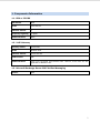
Version Information
Date of Modification
Details of Modification
21 March 2007
Version 1
2
1. Components Information
1.1. PBX or IP-PBX
PBX Vendor
Mitel
Model
3300 ICP MX
Software Version
7
Telephony Signaling
T1 QSIG
Additional Notes
None
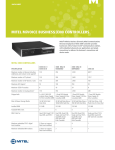
1.2. VoIP Gateway
Gateway Vendor
AudioCodes
Model
Mediant 2000
Software Version
5.00A.039.005
VoIP Protocol
SIP
Additional Notes
Tests were conducted with Mediant 2000. However, these tests are also
applicable to Mediant 1000.
1.3. Microsoft Exchange Server 2007 Unified Messaging
Version
RTM
3
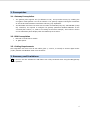
2. Prerequisites
2.1. Gateway Prerequisites
•
The gateway also supports TLS (in addition to TCP). This provides security by enabling the
encryption of SIP packets over the IP network. The gateway supports self-signed certificates
as well as Microsoft Windows Certificates Authority (CA) capabilities.
•
The Mitel PBX must have the same source number for MWI ON (Lamp on) and MWI OFF (Lamp
off). Therefore, it's required to configure the gateway parameter MwiSourceNumber as the
voicemail pilot number (i.e., 2690 in our testing environment example). This number is shown
on the subscribers phone display when the MWI lamp is turned on.
2.2. PBX Prerequisites
•
•
PBX with T1 dual framer module.
T1 QSIG option.
2.3. Cabling Requirements
This integration uses cross-over RJ-48c cables (pairs 1, 2 and 4, 5 crossed) to connect digital trunks
(T1/E1) between and Mediant 2000 trunk interfaces.
3. Summary and Limitations
A check in this box indicates the UM feature set is fully functional when using the PBX/gateway
in question.
4
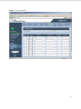
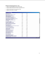
4. Gateway Setup Notes
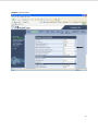
Step 1: SIP Environment Setup
5
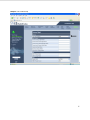
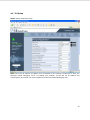
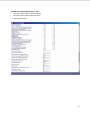
Step 2: Routing Setup
Note: The Proxy IP Address must correspond to the network environment in which the Microsoft
Unified Messaging server is installed (For example, 10.15.3.207 or the FQDN of the Microsoft Unified
Messaging host).
6
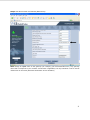
Step 3: Coder Setup
7
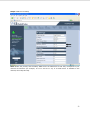
Step 4: Digit Collection Setup
8
Step 5: Supplementary Services Setting
Choose any 4-digit number that is not used in the PBX for Transfer Prefix (e.g., 9989).
9
Step 6: Manipulation Routing Setup
The first manipulation for the destination prefix will strip the 4-digit number of the Transfer Prefix that
was configured in the previous step.
10
Step 7: Trunk Group Setup
11
Step 8: TDM BUS Setting
12
Step 9: Trunk Setting Setup
13
Step 10: FAX Setup
14
Step 11: Voice Mail Setup
15
Step 12: General Setup
16
Step 13:
•
ISDNIBehavior = 1073741824
•
EnableMWI = 1
•
SubscriptionMode = 1
•
EnableDetectRemoteMACChange = 2
•
ECNLPMode = 1
•
MwiSourceNumber = 2690
Note: This parameter should be set to the Voice Mail pilot number (See Step 9 on PBX Setup).
•
TrunkTransferMode_X = 0 (where "X" represents the Trunk number, for example: for the first
trunk TrunkTransferMode_0 = 0)
17
Step 14: Reset Mediant 2000
Click Reset to reset the gateway.
18
4.1. Configuration Files
The ZIP file includes the following files:
1.
AudioCodes Mediant 1000 / Mediant 2000 configuration for TCP environnent (.ini file
extension).
2.
AudioCodes Mediant 1000 / Mediant 2000 configuration for TLS environnent (.ini file
extension).
Mitel 3300 T1 QSIG Audiocodes Mediant 1000 & 2000 TLS.zip
19
4.2. TLS Setup
Step 1: PBX to IP Routing Setup
Note: The Proxy IP Address and Name must correspond to the network environment in which the
Microsoft Unified Messaging server is installed (For example, 10.15.3.207 for IP Address and
exchaneg2007.server2003.com for the FQDN of the Microsoft Unified Messaging host).
20
Step 2: SIP Environment and Gateway Name Setup
Note: Assign an FQDN name to the gateway (for example, gw1.m2k.audiocodes.com). Any gateway
name that corresponds to your network environment is applicable; the only limitation is not to include
underscores in the name (Windows Certification server limitation).
21
Step 3: SIP Environment Setup (Cont.)
22
Step 4: DNS Servers Setup
Note: Define the primary and secondary DNS servers' IP addresses so that they correspond to your
network environment (for example, 10.1.1.11 and 10.1.1.10). If no DNS server is available in the
network, then skip this step.
23
Step 5: Internal DNS Setup
Note: If no DNS server is available in the network, define the internal DNS table where the domain
name is the FQDN of the Microsoft Unified Messaging server and the First IP Address corresponds to
its IP address (for example, exchange2007.com and 10.15.3.207).
24
Step 6: NTP Server Setup
Note: Define the NTP server’s IP address so that it corresponds to your network environment (for
example, 10.15.3.50). If no NTP server is available in the network, then skip this step (as the gateway
uses it’s internal clock).
25
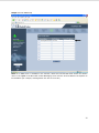
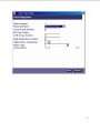
Step 7: Generate Certificate Setup
Use the screen below to generate CSR. Copy the certificate signing request and send it to your
Certification Authority for signing.
26
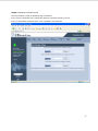
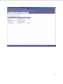
Step 8: Uploading Certificates Setup
The screen below is used to upload the sign certificates.
In the “Server Certificate” area, upload the gateway certificate signed by the CA.
In the “Trusted Root Certificate Store” area, upload the CA certificate.
27
5. PBX Setup Notes
Information used for this test case:
•
Digital VoiceMail ports: T1 QSIG trunk
•
VoiceMail Hunt Group Pilot: 2690
•
VoiceMail User Phone: ext. 2608 and ext. 8999
28
Step 1: Ensure PBX is equipped with T1 PRI Module to Support T1 QSIG
Use the following path to ensure that the PBX is equipped with a T1 PRI module:
System Configuration / UnitsModules / Units Configuration Display.
29
Step 2: Create Class of Service for QSIG Trunks
Use the following path to create CoS for QSIG trunk:
System Configuration / Trunks / Class of Service Options Assignment.
30
Change the following options to 'Yes':
•
ANI/DNIS/ISDN Number Delivery Trunk
•
Call Announce Line
•
Call Forwarding (External Destination)
•
Call Hold - Retrieve with Hold Key
•
Call Reroute after CFFM to busy Destination
31
Change the following options to 'Yes':
•
Display ANI/DNIS/ISDN Calling/Called Number
•
Display DNIS/Called Number Before Digit Modification
•
Display Dialed Digits During Outgoing Calls
•
Display Held Call ID on Transfer
32
Change the following options to 'Yes':
•
Message Waiting - Audible Tone Notification
•
ONS CLASS/CLIP: Message Waiting Activate/Deactivate
•
ONS CLASS/CLIP Set
•
Public Network Access via DPNSS
•
Public Network Identity Provided
•
Public Network to Public Network Connection Allowed
•
Public Trunk
•
R2 Call Progress Tone
33
Change the following options to 'Yes':
•
Third Party Call Forward Follow Me Accept
•
Third Party Call Forward Follow Me Allow
•
Trunk Flash Allowed
34
Step 3: Create Link Descriptor Assignment
Use the following path to create Link Descriptor Assignment:
System Configuration / Trunks / Digital Trunks / ISDN-PRI / Link Descriptor Assignment.
35
Step 4: Create a Digital Link Assignment
Use the following path to create a Digital Link Assignment:
System Configuration / Trunks / Digital Trunks / ISDN-PRI / Digital Link Assignment.
36
37
Step 5: Add MSDN-DPNSS-DASSII Trunk Circuit Descriptor
Use the following path to Add MSDN-DPNSS-DASSII Trunk Circuit Descriptor:
System Configuration / Trunks / Digital Trunks / ISDN-PRI/MSDN-DPNSS-DASSII Trunk
Circuit Descriptor.
38
39
Step 6: Create a Trunk Service Assignment
Use the following path to create a Trunk Service Assignment:
System Configuration / Trunks / Digital Trunks / ISDN-PRI / Trunk Service Assignment.
40
Step 7: Assign Digital Trunks
Use the following path to assign Digital Trunks:
System Configuration / Trunks / Digital Trunks / ISDN-PRI / Digital Trunk Assignment.
41
42
Step 8: Add Trunk Group for QSIG
Use the following path to assign ARS for call routing:
System Administration / Automatic Route Selection / Trunk Group Assignment.
Add a new trunk group for QSIG and add members to this group.
43
Step 9: Add Route Assignment
Use the following path to add Route Assignment:
System Administration / Automatic Route Selection / Route Assignment.
44
45
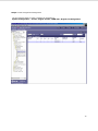
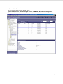
Step 10: Add ARS Digits Dialed Assignment
Use the following path to add ARS Digits Dialed Assignment:
System Administration / Automatic Route Selection / ARS Digits Dialed Assignment.
46
47
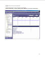
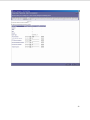
Step 11: Option Assignment
In System Option Assignment, change the following fields:
•
Route Optimization Network ID: change to any unique number.
•
DPNSS/QSIG Diversion Enabled: change to 'Yes'.
48
5.1. TLS Setup
•
N/A.
5.2. Fail-Over Configuration
•
N/A.
5.3. Tested Phones
•
Mitel SuperSet 4025
5.4. Other Comments
None.
49
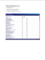
6. Exchange 2007 UM Validation Test Matrix
The following table contains a set of tests for assessing the functionality of the UM core feature set.
The results are recorded as either:
•
Pass (P)
•
Conditional Pass (CP)
•
Fail (F)
•
Not Tested (NT)
•
Not Applicable (NA)
Refer to:
•
Appendix for a more detailed description of how to perform each call scenario.
•
Section 6.1 for detailed descriptions of call scenario failures, if any.
No.
Call Scenarios (see appendix for more
detailed instructions)
(P/CP/F/NT)
1
Dial the pilot number from a phone
extension that is NOT enabled for Unified
Messaging and logon to a user’s mailbox.
P
Reason for Failure (see 6.1
detailed descriptions)
for
more
Confirm hearing the prompt: “Welcome,
you are connected to Microsoft Exchange.
To access your mailbox, enter your
extension…”
2
Navigate mailbox using the Voice User
Interface (VUI).
P
3
Navigate mailbox using the Telephony
User Interface (TUI).
P
4
Dial user extension and leave a voicemail.
4a
Dial user extension and leave a voicemail
from an internal extension.
P
Confirm the Active Directory name of the
calling party is displayed in the sender
field of the voicemail message.
4b
Dial user extension and leave a voicemail
from an external phone.
P
Confirm the correct phone number of the
calling party is displayed in the sender
field of the voicemail message.
5
Dial Auto Attendant (AA).
P
50
Dial the extension for the AA and confirm
the AA answers the call.
6
Call Transfer by Directory Search.
6a
Call Transfer by Directory Search and
have the called party answer.
P
Confirm the correct called party answers
the phone.
6b
Call Transfer by Directory Search when
the called party’s phone is busy.
P
Confirm the call is routed to the called
party’s voicemail.
6c
Call Transfer by Directory Search when
the called party does not answer.
P
Confirm the call is routed to the called
party’s voicemail.
6d
Setup an invalid extension number for a
particular user. Call Transfer by Directory
Search to this user.
P
Microsoft UM informs the following: “The call
can’t be transferred. Return to main menu”.
Confirm the number is reported as invalid.
7
Outlook Web Access
Phone Feature.
(OWA)
Play-On-
7a
Listen to voicemail using OWA’s Play-OnPhone feature to a user’s extension.
P
7b
Listen to voicemail using OWA’s Play-OnPhone feature to an external number.
P
8
Configure a button on the phone of a UMenabled user to forward the user to the
pilot number. Press the voicemail button.
P
Confirm you are sent to the prompt:
“Welcome, you are connected to Microsoft
Exchange. <User>. Please enter your pin
and press the pound key.”
9
Send a test
extension.
FAX
message
to
user
P
51
Confirm the FAX is received in the user’s
inbox.
10
Setup TLS between gateway/IP-PBX and
Exchange UM.
Windows Certificate Authority (CA).
10a
Dial the pilot number and logon to a
user’s mailbox.
P
Confirm UM answers the call and confirm
UM responds to DTMF input.
10b
Dial a user
voicemail.
extension
and
leave
a
P
user
P
Confirm the user receives the voicemail.
10c
Send a test
extension.
FAX
message
to
Confirm the FAX is received in the user’s
inbox.
11
Setup G.723.1 on the gateway. (If
already using G.723.1, setup G.711 A Law
or G.711 Mu Law for this step).
P
Dial the pilot number and confirm the UM
system answers the call.
12
Setup Message Waiting Indicator (MWI).
P
Geomant offers a third party solution:
MWI 2007. Installation files and product
documentation
can
be
found
on
Geomant’s MWI 2007 website.
13
Execute Test-UMConnectivity.
NT
14
Setup and test fail-over configuration on
the IP-PBX to work with two UM servers.
NA
52
6.1. Detailed Description of Limitations
Failure Point
None
Phone type (if phone-specific)
Call scenarios(s) associated with failure point
List of UM features affected by failure point
Additional Comments
53
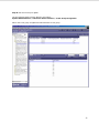
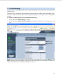
7. Troubleshooting
The tools used for debugging include network sniffer applications (such as Ethereal) and AudioCodes'
Syslog protocol.
The Syslog client, embedded in the AudioCodes gateways (MP-11x, Mediant 1000, and Mediant 2000),
sends error reports/events generated by the gateway application to a Syslog server, using IP/UDP
protocol.
To activate the Syslog client on the AudioCodes gateways:
1.
Set the parameter Enable Syslog to 'Enable'.
2.
Use the parameter Syslog Server IP Address to define the IP address of the Syslog server you
use.
Step 2
Step 1
Note: The Syslog Server IP address must be one that corresponds to your network environment in
which the Syslog server is installed (for example, 10.15.2.5).
54
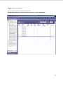
3.
To determine the Syslog logging level, use the parameter Debug Level and set this parameter to
'5'.
4.
Change the CDR Report Level to 'End Call' to enable additional call information.
Step 4
Step 3
AudioCodes has also developed advanced diagnostic tools that may be used for high-level
troubleshooting. These tools include the following:
•
PSTN Trace: PSTN Trace is a procedure used to monitor and trace the PSTN elements (E1/T1) in
AudioCodes digital gateways (Mediant 1000 & Mediant 2000). These utilities are designed to
convert PSTN trace binary files to textual form.
•
DSP Recording: DSP recording is a procedure used to monitor the DSP operation (e.g., rtp packets
and events).
55
Appendix
1. Dial Pilot Number and Mailbox Login
•
Dial the pilot number of the UM server from an extension that is NOT enabled for UM.
•
Confirm hearing the greeting prompt: “Welcome, you are connected to Microsoft Exchange. To
access your mailbox, enter your extension...”
•
Enter the extension, followed by the mailbox PIN of an UM-enabled user.
•
Confirm successful logon to the user’s mailbox.
2. Navigate Mailbox using Voice User Interface (VUI)
•
Logon to a user’s UM mailbox.
•
If the user preference has been set to DTMF tones, activate the Voice User Interface (VUI)
under personal options.
•
Navigate through the mailbox and try out various voice commands to confirm that the VUI is
working properly.
•
This test confirms that the RTP is flowing in both directions and speech recognition is working
properly.
3. Navigate Mailbox using Telephony User Interface (TUI)
•
Logon to a user’s UM mailbox.
•
If the user preference has been set to voice, press “#0” to activate the Telephony User
Interface (TUI).
•
Navigate through the mailbox and try out the various key commands to confirm that the TUI is
working properly.
•
This test confirms that both the voice RTP and DTMF RTP (RFC 2833) are flowing in both
directions.
4. Dial User Extension and Leave Voicemail
•
Note: If you are having difficulty reaching the user’s UM voicemail, verify that the coverage
path for the UM-enabled user’s phone is set to the pilot number of the UM server.
a. From an Internal Extension
a.
From an internal extension, dial the extension for a UM-enabled user and leave a
voicemail message.
b.
Confirm the voicemail message arrives in the called user’s inbox.
c.
Confirm this message displays a valid Active Directory name as the sender of this
voicemail.
56
b. From an External Phone
a.
From an external phone, dial the extension for a UM-enabled user and leave a
voicemail message.
b.
Confirm the voicemail message arrives in the called user’s inbox.
c.
Confirm this message displays the phone number as the sender of this voicemail.
5. Dial Auto Attendant(AA)
•
Create an Auto Attendant using the Exchange Management Console:
a.
Under the Exchange Management Console, expand “Organizational Configuration” and
then click on “Unified Messaging”.
b.
Go to the Auto Attendant tab under the results pane.
c.
Click on the “New Auto Attendant…” under the action pane to invoke the AA wizard.
d.
Associate the AA with the appropriate dial plan and assign an extension for the AA.
e.
Create PBX dialing rules to always forward calls for the AA extension to the UM server.
f.
Confirm the AA extension is displayed in the diversion information of the SIP Invite.
•
Dial the extension of Auto Attendant.
•
Confirm the AA answers the call.
6. Call Transfer by Directory Search
•
Method one: Pilot Number Access
•
Dial the pilot number for the UM server from a phone that is NOT enabled for UM.
•
To search for a user by name:
•
Press # to be transferred to name Directory Search.
•
•
•
Call Transfer by Directory Search by entering the name of a user in the same
Dial Plan using the telephone keypad, last name first.
To search for a user by email alias:
•
Press “#” to be transferred to name Directory Search
•
Press “# #” to be transferred to email alias Directory Search
•
Call Transfer by Directory Search by entering the email alias of a user in the
same Dial Plan using the telephone keypad, last name first.
Method two: Auto Attendant
•
Follow the instructions in appendix section 5 to setup the AA.
•
Call Transfer by Directory Search by speaking the name of a user in the same Dial
Plan. If the AA is not speech enabled, type in the name using the telephone keypad.
57
•
Note: Even though some keys are associated with three or four numbers, for each letter, each
key only needs to be pressed once regardless of the letter you want. Ignore spaces and
symbols when spelling the name or email alias.
a. Called Party Answers
•
Call Transfer by Directory Search to a user in the same dial plan and have the called party
answer.
•
Confirm the call is transferred successfully.
b. Called Party is Busy
•
Call Transfer by Directory Search to a user in the same dial plan when the called party is busy.
•
Confirm the calling user is routed to the correct voicemail.
c. Called Party does not Answer
•
Call Transfer by Directory Search to a user in the same dial plan and have the called party not
answer the call.
•
Confirm the calling user is routed to the correct voicemail.
d. The Extension is Invalid
•
Assign an invalid extension to a user in the same dial plan. An invalid extension has the same
number of digits as the user’s dial plan and has not been mapped on the PBX to any user or
device.
a.
UM Enable a user by invoking the “Enable-UMMailbox” wizard.
b.
Assign an unused extension to the user.
c.
Do not map the extension on the PBX to any user or device.
d.
Call Transfer by Directory Search to this user.
e.
Confirm the call fails and the caller is prompted with appropriate messages.
7. Play-On-Phone
•
To access play-on-phone:
a.
Logon to Outlook Web Access (OWA) by going to URL https://<server name>/owa.
b.
After receiving a voicemail in the OWA inbox, open this voicemail message.
c.
At the top of this message, look for the Play-On-Phone field (
d.
Click this field to access the Play-On-Phone feature.
Play on Phone...).
a. To an Internal Extension
•
Dial the extension for a UM-enabled user and leave a voicemail message.
•
Logon to this called user’s mailbox in OWA.
58
•
Once it is received in the user’s inbox, use OWA’s Play-On-Phone to dial an internal extension.
•
Confirm the voicemail is delivered to the correct internal extension.
b. To an External Phone number
•
Dial the extension for a UM-enabled user and leave a voicemail message.
•
Logon to the UM-enabled user’s mailbox in OWA.
•
Confirm the voicemail is received in the user’s mailbox.
•
Use OWA’s Play-On-Phone to dial an external phone number.
•
Confirm the voicemail is delivered to the correct external phone number.
•
Troubleshooting:
a.
Make sure the appropriate UMMailboxPolicy dialing rule is configured to make this call.
As an example, open an Exchange Management Shell and type in the following
commands:
b.
$dp = get-umdialplan -id <dial plan ID>
c.
$dp.ConfiguredInCountryOrRegionGroups.Clear()
d.
$dp.ConfiguredInCountryOrRegionGroups.Add("anywhere,*,*,")
e.
$dp.AllowedInCountryOrRegionGroups.Clear()
f.
$dp.AllowedInCountryOrRegionGroups.Add(“anywhere")
g.
$dp|set-umdialplan
h.
$mp = get-ummailboxpolicy -id <mailbox policy ID>
i.
$mp.AllowedInCountryGroups.Clear()
j.
$mp.AllowedInCountryGroups.Add("anywhere")
k.
$mp|set-ummailboxpolicy
l.
The user must be enabled for external dialing on the PBX.
m. Depending on how the PBX is configured, you may need to prepend the trunk access
code (e.g. 9) to the external phone number.
8. Voicemail Button
•
Configure a button on the phone of a UM-enabled user to route the user to the pilot number of
the UM server.
•
Press this voicemail button on the phone of an UM-enabled user.
•
Confirm you are sent to the prompt: “Welcome, you are connected to Microsoft Exchange.
<User Name>. Please enter your pin and press the pound key.”
•
Note: If you are not hearing this prompt, verify that the button configured on the phone
passes the user’s extension as the redirect number. This means that the user extension should
appear in the diversion information of the SIP invite.
59
9. FAX
•
Use the Management Console or the Management Shell to FAX-enable a user.
•
Management Console:
•
a.
Double click on a user’s mailbox and go to Mailbox Features tab.
b.
Click Unified Messaging and then click the properties button.
c.
Check the box “Allow faxes to be received”.
Management Shell - execute the following command:
a.
•
Set-UMMailbox –identity UMUser –FaxEnabled:$true
To test fax functionality:
a.
Dial the extension for this fax-enabled UM user from a fax machine.
b.
Confirm the fax message is received in the user’s inbox.
c.
Note: You may notice that the UM server answers the call as though it is a voice call
(i.e. you will hear: “Please leave a message for…”). When the UM server detects the
fax CNG tones, it switches into fax receiving mode, and the voice prompts terminate.
d.
Note: UM only support T.38 for sending fax.
10.TRANSPORT SECURITY LAYER (TLS)
•
Setup TLS on the gateway/IP-PBX and Exchange 2007 UM.
•
Import/Export all the appropriate certificates.
a. Dial Pilot Number and Mailbox Login
•
Execute the steps in scenario 1 (above) with TLS turned on.
b. Dial User Extension and Leave a Voicemail
•
Execute the steps in scenario 4 (above) with TLS turned on.
c. FAX
•
Execute the steps in scenario 9 (above) with TLS turned on.
11.G.723.1
•
Configure the gateway to use the G.723.1 codec for sending audio to the UM server.
•
If already using G.723.1 for the previous set of tests, use this step to test G.711 A Law or
G.711 Mu Law instead.
•
Call the pilot number and verify the UM server answers the call.
•
Note: If the gateway is configured to use multiple codecs, the UM server, by default, will use
the G.723.1 codec if it is available.
60
12.Message Waiting Indicator (MWI)
•
Although Exchange 2007 UM does not natively support MWI, Geomant has created a 3rd party
solution - MWI2007. This product also supports SMS message notification.
•
Installation files and product documentation can be found on Geomant’s MWI 2007 website.
13.Test-UMConnectivity
•
Run the Test-UMConnectivity diagnostic cmdlet by executing the following command in
Exchange Management Shell:
•
Test-UMConnectivity –UMIPGateway:<Gateway> -Phone:<Phone> |fl
•
<Gateway> is the name (or IP address) of the gateway which is connected to UM, and
through which you want to check the connectivity to the UM server. Make sure the gateway is
configured to route calls to UM.
•
<Phone> is a valid UM extension. First, try using the UM pilot number for the hunt-group
linked to the gateway. Next, try using a CFNA number configured for the gateway. Please
ensure that a user or an AA is present on the UM server with that number.
•
The output shows the latency and reports if it was successful or there were any errors.
14.Test Fail-Over Configuration on IP-PBX with Two UM Servers
•
This is only required for direct SIP integration with IP-PBX. If the IP-PBX supports fail-over
configuration (e.g., round-robin calls between two or more UM servers):
a.
Provide the configuration steps in Section 5.
b.
Configure the IP-PBX to work with two UM servers.
c.
Simulate a failure in one UM server.
d.
Confirm the IP-PBX transfers new calls to the other UM server successfully.
61